SIMPLE HYDRAULIC ELEVATOR CONTROLLER MANUAL Hydro S Manual v2.0.pdf · SIMPLE HYDRAULIC ELEVATOR...
128
SIMPLE HYDRAULIC ELEVATOR CONTROLLER MANUAL GAL Manufacturing Corp 50 E 153 rd Street Bronx, NY 10451 Technical Support: 1-877-425-7778
-
Upload
phamnguyet -
Category
Documents
-
view
239 -
download
1
Transcript of SIMPLE HYDRAULIC ELEVATOR CONTROLLER MANUAL Hydro S Manual v2.0.pdf · SIMPLE HYDRAULIC ELEVATOR...
SIMPLE HYDRAULIC ELEVATOR CONTROLLER
MANUAL
GAL Manufacturing Corp
50 E 153rd Street
Bronx, NY 10451
Technical Support: 1-877-425-7778
i
FOREWORD
G.A.L. has developed this manual with usability and safety in mind. General and specific safety notices and precautions are defined in the manual. However, G.A.L. cannot be responsible for any injury to persons or damage to property (including the elevator equipment) resulting from negligence, misuse of the equipment, misinterpretation of instructions included in this manual, or due to any other cause beyond the control of G.A.L. All drawings, illustrations and information herein are the proprietary property of G.A.L. and must not be made public or reproduced by any individual or entity other than the purchaser hereof without the express written permission of G.A.L. (REV 2.0 March 2016)
ii
TABLE OF CONTENTS
FOREWORD ................................................................................................. I
IMPORTANT WARNINGS AND NOTES .................................................... V
SECTION 1 - GENERAL PRODUCT DESCRIPTION ................................. 6
1.1 INTRODUCTION .................................................................................................................. 6 1.1.1 PHYSICAL LAYOUT OF THE CONTROLLER ............................................................... 7 1.1.2 SELECTOR SYSTEM ..................................................................................................... 9 1.1.3 SLOWDOWN MAGNETS ............................................................................................... 9 1.1.4 SECONDARY SPEED FEEDBACK ............................................................................. 10 1.1.5 BINARY PRESET MAGNETS ...................................................................................... 17 1.1.6 MODES OF OPERATION ............................................................................................ 18
SECTION – 2 INSTALLATION OF THE GALAXY CONTROLLER .......... 24
2.1 GENERAL INFORMATION ............................................................................................... 24 2.2 SITE SELECTION .............................................................................................................. 24 2.3 ENVIRONMENTAL CONSIDERATIONS .......................................................................... 24 2.4 WIRING GUIDELINES AND INSTRUCTIONS .................................................................. 24
2.4.1 THE WIRING PRINTS .................................................................................................. 24 2.4.2 GROUND WIRING ....................................................................................................... 24 2.4.3 HOISTWAY WIRING .................................................................................................... 25 2.4.4 ELEVATOR CAR WIRING ............................................................................................ 25 2.4.5 MACHINE ROOM WIRING ........................................................................................... 25 2.4.6 WIRING TO TOP OF CAR SELECTOR ....................................................................... 25 2.4.7 SLOWDOWN LIMIT SWITCHES .................................................................................. 25 2.4.8 NORMAL AND FINAL LIMIT SWITCHES .................................................................... 26 Table 2.0: Slowdown Distances from Terminal Landing ....................................................... 26
SECTION 3 - ADJUSTMENT OF THE GALAXY HYDRAULIC CONTROLLER .......................................................................................... 27
3.1 GENERAL INFORMATION ............................................................................................... 27 3.1 INITIAL POWER-UP .......................................................................................................... 27
3.1.1 CHECK MAIN-LINE VOLTAGE .................................................................................... 27 3.1.2 SET TOGGLE SWITCHES ........................................................................................... 27 3.1.3 MAKE SURE THE CAR IS SAFE ................................................................................. 27 3.1.4 CHECK CONTROLLER VOLTAGE .............................................................................. 27 3.1.5 VERIFY THE LCD GALaxy IS BLINKING .................................................................... 28 3.1.6 PRESET ADJUSTABLE VARIABLES ON SAFETY PROCESSOR BOARD ............... 28 3.1.7 PLACE STOP SWICTH IN RUN POSITION ................................................................ 28 3.1.8 PUMP MOTOR ROTATION ......................................................................................... 28 3.1.9 READY TO RUN ON INSPECTION ............................................................................. 29 3.1.10 CHECK SELECTOR INPUTS ..................................................................................... 30 3.1.11 VERIFY SLOWDOWN LIMITS ................................................................................... 31 3.1.12 VERIFY CAR SPEED ON SAFETY PROCESSOR BOARD ...................................... 31 3.1.13 CORRECT CAR SPEED WHEN USING A TAPE ...................................................... 31

iii
3.1.14 CORRECT CAR SPEED WHEN USING AN ENCODER ........................................... 31 3.2 FINAL ADJUSTMENT ....................................................................................................... 32
3.2.1 AUTOMATIC RUN ........................................................................................................ 32 3.2.2 SET FLOOR DEAD ZONE ........................................................................................... 32 3.2.3 ADJUST VALVE ........................................................................................................... 32 3.2.4 ADJUST SAFETY PROCESSOR BOARD SPEED CLAMPS ...................................... 32 3.2.5 VERIFY INSPECTION VELOCITY CLAMP ON SAFETY PROCESSOR BOARD....... 33 3.2.6 ENABLE DOORS ......................................................................................................... 33 3.2.7 FINE TUNE RIDE AND STOPS ................................................................................... 33 3.2.8 FINE TUNE PARAMETERS ......................................................................................... 33
SECTION 4 - TROUBLESHOOTING ........................................................ 34
4.1 GENERAL INFORMATION ............................................................................................... 34 4.2 MICROPROCESSOR CPU ................................................................................................ 34 4.3 INPUT/OUTPUT BOARDS ................................................................................................ 34 4.4 RUN SEQUENCE .............................................................................................................. 36
Figure 4.1: Run Sequence. ................................................................................................... 36 4.5 THE SAFETY PROCESSOR BOARD ............................................................................... 36
............................................................................................................................................... 37 Figure 4.1a: Safety Processor Board (GALX-1066) ............................................................. 37
4.6 MAIN CPU FAULTS .......................................................................................................... 38 4.6.1 DETAILED FAULT DATA ............................................................................................. 48 4.6.2 SAFETY PROCESSOR FAULTS ................................................................................. 58
SECTION 5 - LCD INTERFACE ................................................................ 59
5.1 OPERATING THE LCD INTERFACE ................................................................................ 59 5.2 THE LCD MENU STRUCTURE ......................................................................................... 60 5.3 SET DATE AND TIME ....................................................................................................... 61 5.3 ADJUSTABLE VARIABLES ............................................................................................. 62 5.4 Field Adjustable Variables ............................................................................................... 63 5.5 JOB STATISTICS .............................................................................................................. 83 5.6 VIEW JOB STATISTICS .................................................................................................... 84 5.7 CLEAR JOB STATISTICS ................................................................................................. 86 5.8 INPUTS AND OUTPUTS ................................................................................................... 87 5.9 CAR INPUTS AND OUTPUTS .......................................................................................... 88 5.10 GROUP INPUTS AND OUTPUTS ................................................................................... 89 5.11 SET CALLS AND LOCKOUTS ....................................................................................... 90 5.12 SETUP CAR CALLS ........................................................................................................ 91 5.13 SETUP DOWN HALL CALLS ......................................................................................... 92 5.14 SETUP UP HALL CALLS ................................................................................................ 93 5.15 LOCKOUT FRONT CAR CALL ....................................................................................... 94 5.16 ELEVATOR STATUS ...................................................................................................... 95 5.17 FAULT LOG ..................................................................................................................... 99 5.18 VIEW FAULT LOG ......................................................................................................... 100 5.19 CLEAR FAULT LOG ..................................................................................................... 101 5.20 RESET LOW/HOT OIL .................................................................................................. 102 5.21 SELECT VIDEO DISPLAY ............................................................................................ 103 5.22 SOFTWARE VERSION .................................................................................................. 104 5.23 DIAGNOSTICS .............................................................................................................. 105
iv
5.24 VIEW SYSTEM STATUS LOG ...................................................................................... 106 5.25 CLEAR SYSTEM STATUS LOG ................................................................................... 107 5.26 GROUP COMM STATUS .............................................................................................. 108 5.27 CLEAR GROUP COMM STATUS ................................................................................. 109
SECTION 6 - SAFETY PROCESSOR LCD INTERFACE ....................... 110
6.1 OPERATING THE LCD INTERFACE .............................................................................. 110 6.2 THE SAFETY PROCESSOR BOARD LCD MENU STRUCTURE .................................. 111 6.3 ELEVATOR SERVICE ..................................................................................................... 112 6.4 CAR SPEED .................................................................................................................... 113 6.5 SAFETY PROCESSOR PULSE COUNT ........................................................................ 113 6.6 SAFETY PROCESSOR ADJUSTABLE VARIABLES .................................................... 114 6.7 SAFETY PROCESSOR ADJUSTABLE VARIABLES .................................................... 115 6.8 SAFETY PROCESSOR INPUTS AND OUTPUTS .......................................................... 117 6.9 LIMIT VELOCITY ............................................................................................................. 119 6.10 SAFETY PROCESSOR FAULTS .................................................................................. 120 6.11 CLEAR FAULTS ............................................................................................................ 122 6.12 RESET SAFETY PROCESSOR FAULT LATCH .......................................................... 122 6.13 SAFETY PROCESSOR BOARD TEMPERATURE ....................................................... 123 6.14 SAFETY PROCESSOR EXTERNAL TEMPERATURE................................................. 123
APPENDIX A ........................................................................................... 124
Description of I/O Mnemonics ............................................................................................. 124
v
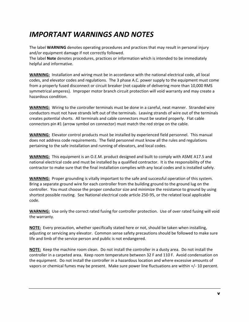
IMPORTANT WARNINGS AND NOTES The label WARNING denotes operating procedures and practices that may result in personal injury and/or equipment damage if not correctly followed. The label Note denotes procedures, practices or information which is intended to be immediately helpful and informative. WARNING: Installation and wiring must be in accordance with the national electrical code, all local codes, and elevator codes and regulations. The 3 phase A.C. power supply to the equipment must come from a properly fused disconnect or circuit breaker (not capable of delivering more than 10,000 RMS symmetrical amperes). Improper motor branch circuit protection will void warranty and may create a hazardous condition. WARNING: Wiring to the controller terminals must be done in a careful, neat manner. Stranded wire conductors must not have strands left out of the terminals. Leaving strands of wire out of the terminals creates potential shorts. All terminals and cable connectors must be seated properly. Flat cable connectors pin #1 (arrow symbol on connector) must match the red stripe on the cable. WARNING: Elevator control products must be installed by experienced field personnel. This manual does not address code requirements. The field personnel must know all the rules and regulations pertaining to the safe installation and running of elevators, and local codes. WARNING: This equipment is an O.E.M. product designed and built to comply with ASME A17.5 and national electrical code and must be installed by a qualified contractor. It is the responsibility of the contractor to make sure that the final installation complies with any local codes and is installed safely. WARNING: Proper grounding is vitally important to the safe and successful operation of this system. Bring a separate ground wire for each controller from the building ground to the ground lug on the controller. You must choose the proper conductor size and minimize the resistance to ground by using shortest possible routing. See National electrical code article 250-95, or the related local applicable code. WARNING: Use only the correct rated fusing for controller protection. Use of over rated fusing will void the warranty. NOTE: Every precaution, whether specifically stated here or not, should be taken when installing, adjusting or servicing any elevator. Common sense safety precautions should be followed to make sure life and limb of the service person and public is not endangered. NOTE: Keep the machine room clean. Do not install the controller in a dusty area. Do not install the controller in a carpeted area. Keep room temperature between 32 F and 110 F. Avoid condensation on the equipment. Do not install the controller in a hazardous location and where excessive amounts of vapors or chemical fumes may be present. Make sure power line fluctuations are within +/- 10 percent.
6
Section 1 - GENERAL PRODUCT DESCRIPTION
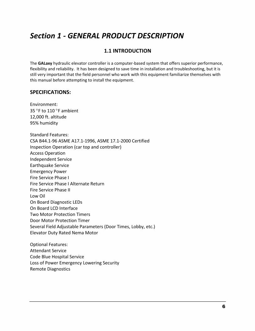
1.1 INTRODUCTION The GALaxy hydraulic elevator controller is a computer-based system that offers superior performance, flexibility and reliability. It has been designed to save time in installation and troubleshooting, but it is still very important that the field personnel who work with this equipment familiarize themselves with this manual before attempting to install the equipment.
SPECIFICATIONS:
Environment:
35 F to 110 F ambient 12,000 ft. altitude 95% humidity
Standard Features: CSA B44.1-96 ASME A17.1-1996, ASME 17.1-2000 Certified Inspection Operation (car top and controller) Access Operation Independent Service Earthquake Service Emergency Power Fire Service Phase I Fire Service Phase I Alternate Return Fire Service Phase II Low Oil On Board Diagnostic LEDs On Board LCD Interface Two Motor Protection Timers Door Motor Protection Timer Several Field Adjustable Parameters (Door Times, Lobby, etc.) Elevator Duty Rated Nema Motor
Optional Features: Attendant Service Code Blue Hospital Service Loss of Power Emergency Lowering Security Remote Diagnostics
7
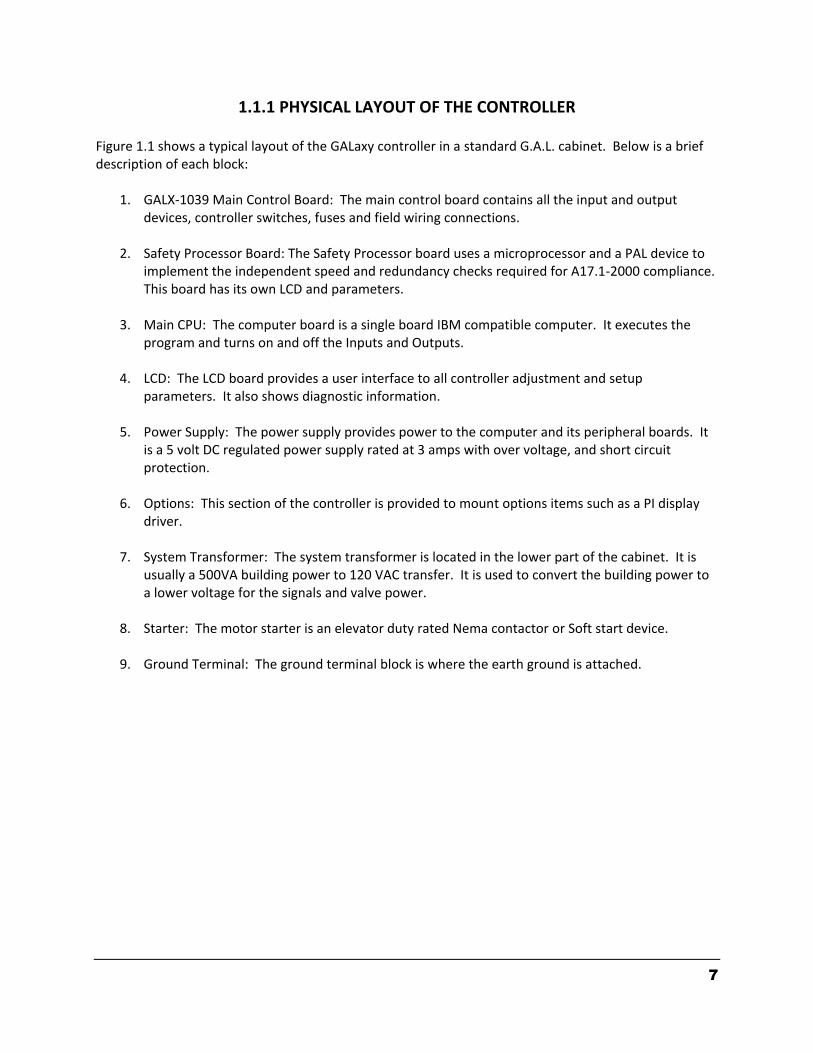
1.1.1 PHYSICAL LAYOUT OF THE CONTROLLER Figure 1.1 shows a typical layout of the GALaxy controller in a standard G.A.L. cabinet. Below is a brief description of each block:
1. GALX-1039 Main Control Board: The main control board contains all the input and output devices, controller switches, fuses and field wiring connections.
2. Safety Processor Board: The Safety Processor board uses a microprocessor and a PAL device to
implement the independent speed and redundancy checks required for A17.1-2000 compliance. This board has its own LCD and parameters.
3. Main CPU: The computer board is a single board IBM compatible computer. It executes the
program and turns on and off the Inputs and Outputs.
4. LCD: The LCD board provides a user interface to all controller adjustment and setup parameters. It also shows diagnostic information.
5. Power Supply: The power supply provides power to the computer and its peripheral boards. It
is a 5 volt DC regulated power supply rated at 3 amps with over voltage, and short circuit protection.
6. Options: This section of the controller is provided to mount options items such as a PI display
driver.
7. System Transformer: The system transformer is located in the lower part of the cabinet. It is usually a 500VA building power to 120 VAC transfer. It is used to convert the building power to a lower voltage for the signals and valve power.
8. Starter: The motor starter is an elevator duty rated Nema contactor or Soft start device.
9. Ground Terminal: The ground terminal block is where the earth ground is attached.
8
Safety Processor
LCD Display
GALX-1039Main Control Board
Main CPU
Options
PowerSupply
Starter
TransformerGround
Terminal
Figure 1.1 Typical Physical Layout

9
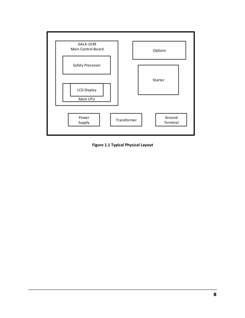
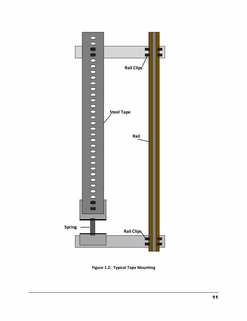
1.1.2 SELECTOR SYSTEM The selector system for the GALaxy controller uses a steel tape that is hung the length of the hoistway. A set of magnets are placed on the tape at each floor having one 8” magnet as the door zone magnet and two smaller 4” magnets as slowdowns. The selector is mounted on the car and is guided along the tape by nylon guides to keep the tape and magnets the proper distance from the selector sensors. The controller uses the door zone magnet to determine the elevator’s level position to the floor. The tape is installed by first attaching it at the top of the hoistway approximately 12 inches from the rail, see Figure 1.2. The tape is then unreeled from the top of the car while running down on inspection. At the bottom of the hoistway it is attached with a spring to keep it taut. The selector is then mounted on the top of the car and is connected to the tape by the nylon guides. Figure 1.3 shows a typical mounting of the selector to the crosshead. To install the floor magnets, the car is placed dead level to the desired floor. The tape is then marked at the top left of the selector through a factory cut guide hole. The car is moved below the floor so the tape can be accessed where the selector was sitting at floor level. A door zone template, provided by G.A.L., is placed at the mark and the door zone magnet and binary position preset magnets (if used) are placed at the appropriate locations in the template. The template is then removed from the tape. The slowdown magnets are then placed at the measured distance on the tape above and below the floor. The location of each magnet is shown in Figures1.4 when selector board A1011 is used or Figures 1.5 or 1.6 when selector board PCB-1011BN is used. Figures 1.3a and 1.3b show the two types of selector boards.
1.1.3 SLOWDOWN MAGNETS The slowdown magnets are used to signal the CPU to transfer to leveling speed (to turn off the high speed output). Table 1.0 shows the slowdown magnet distances with respect to contract speed. All distances are show in inches. Distances are from the middle of the door zone magnet to the middle of US, DS magnets.
Table 1.0: Slowdown Distances
fpm US, DS
100 20”
150 30”
200 40”
250 50”

10
1.1.4 SECONDARY SPEED FEEDBACK The tape is perforated with 3/8 inch holes every 3/8 of an inch. A sensor is mounted on the selector to provide a secondary speed feedback to the Safety Processor Board. The Safety Processor uses this velocity to verity that the car is traveling at a safe speed when slowdown limits are hit, when the car doors are open and when running on inspection. There are three types of inputs used to verify the car speed at the terminal landing. Traction cars with distance feedback use the normal slowdown limits “UT & DT” and the emergency slowdown limits “UTS & DTS”. Hydro and traction non-distance feedback cars use the level sensors from the selector “UL & DL” at the terminal landings for the velocity check and are validated with “UTS & DTS” emergency slowdown limits. For all control systems, the “UT & DT” limits are used to verify the operation of “UTS & DTS”.
11
Rail Clips
Rail
Rail Clips
Steel Tape
Spring
Figure 1.2: Typical Tape Mounting
12
Figure 1.3: Typical Mounting of Selector
13
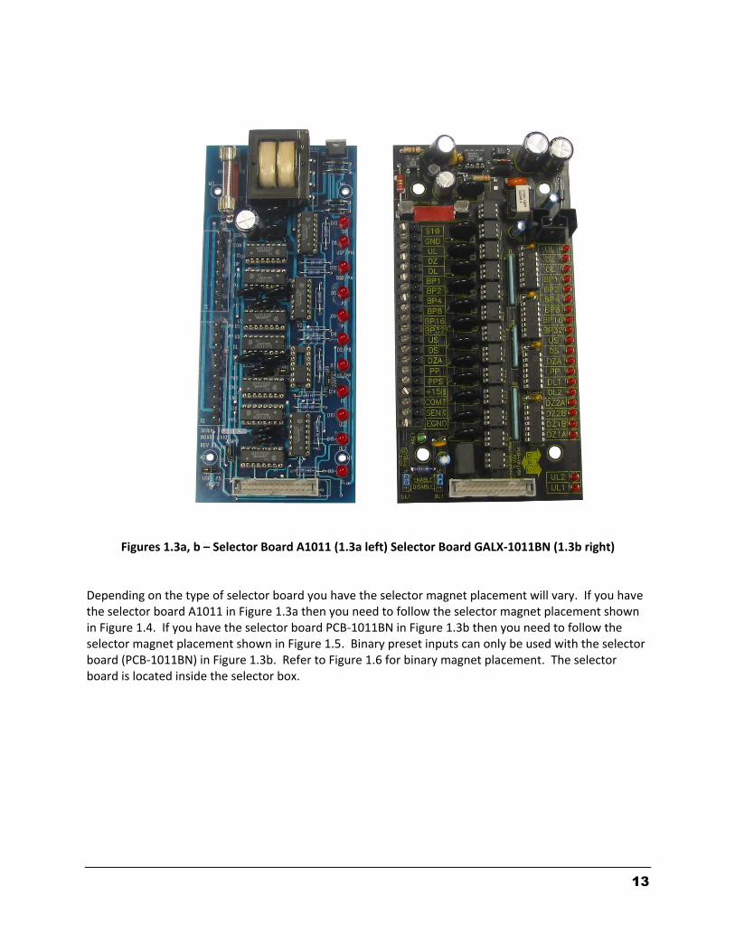
Figures 1.3a, b – Selector Board A1011 (1.3a left) Selector Board GALX-1011BN (1.3b right)
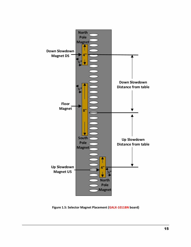
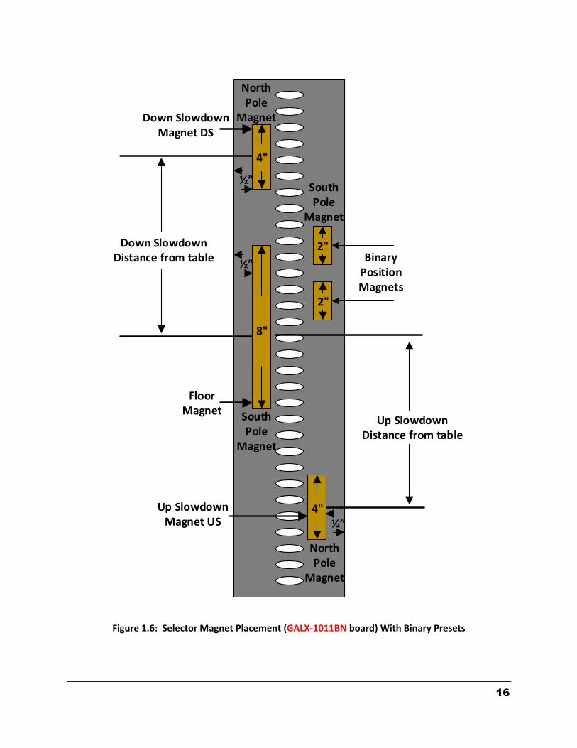
Depending on the type of selector board you have the selector magnet placement will vary. If you have the selector board A1011 in Figure 1.3a then you need to follow the selector magnet placement shown in Figure 1.4. If you have the selector board PCB-1011BN in Figure 1.3b then you need to follow the selector magnet placement shown in Figure 1.5. Binary preset inputs can only be used with the selector board (PCB-1011BN) in Figure 1.3b. Refer to Figure 1.6 for binary magnet placement. The selector board is located inside the selector box.

14
4"
4"
8"
½”
½”
Down Slowdown Magnet DS
Up SlowdownMagnet US
FloorMagnet
Up Slowdown Distance from table
Down Slowdown Distance from table
Figure 1.4: Selector Magnet Placement (A1011 board)
15
4"
8"
½”
½”
Down Slowdown Magnet DS
Up SlowdownMagnet US
FloorMagnet
Up Slowdown Distance from table
Down Slowdown Distance from table
4"
4"½”
NorthPole
Magnet
NorthPole
Magnet
SouthPole
Magnet
Figure 1.5: Selector Magnet Placement (GALX-1011BN board)
16
4"
8"
½”
½”
Down Slowdown Magnet DS
Up SlowdownMagnet US
FloorMagnet
Up Slowdown Distance from table
Down Slowdown Distance from table
4"
4"½”
NorthPole
Magnet
NorthPole
Magnet
SouthPole
Magnet
2"
2"
SouthPole
Magnet
BinaryPosition Magnets
Figure 1.6: Selector Magnet Placement (GALX-1011BN board) With Binary Presets
17
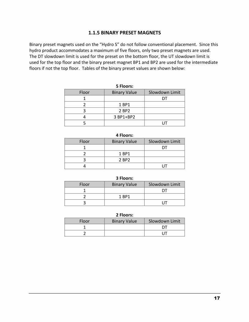
1.1.5 BINARY PRESET MAGNETS
Binary preset magnets used on the “Hydro S” do not follow conventional placement. Since this hydro product accommodates a maximum of five floors, only two preset magnets are used. The DT slowdown limit is used for the preset on the bottom floor, the UT slowdown limit is used for the top floor and the binary preset magnet BP1 and BP2 are used for the intermediate floors if not the top floor. Tables of the binary preset values are shown below:
5 Floors:
Floor Binary Value Slowdown Limit
1 DT
2 1 BP1
3 2 BP2
4 3 BP1+BP2
5 UT
4 Floors:
Floor Binary Value Slowdown Limit
1 DT
2 1 BP1
3 2 BP2
4 UT
3 Floors:
Floor Binary Value Slowdown Limit
1 DT
2 1 BP1
3 UT
2 Floors:
Floor Binary Value Slowdown Limit
1 DT
2 UT
18
1.1.6 MODES OF OPERATION
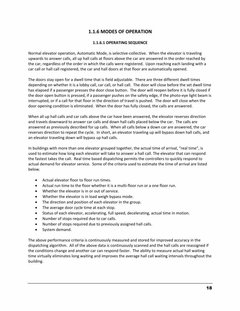
1.1.6.1 OPERATING SEQUENCE Normal elevator operation, Automatic Mode, is selective-collective. When the elevator is traveling upwards to answer calls, all up hall calls at floors above the car are answered in the order reached by the car, regardless of the order in which the calls were registered. Upon reaching each landing with a car call or hall call registered, the car and hall doors at that floor are automatically opened. The doors stay open for a dwell time that is field adjustable. There are three different dwell times depending on whether it is a lobby call, car call, or hall call. The door will close before the set dwell time has elapsed if a passenger presses the door close button. The door will reopen before it is fully closed if the door open button is pressed, if a passenger pushes on the safety edge, if the photo-eye light beam is interrupted, or if a call for that floor in the direction of travel is pushed. The door will close when the door opening condition is eliminated. When the door has fully closed, the calls are answered. When all up hall calls and car calls above the car have been answered, the elevator reverses direction and travels downward to answer car calls and down hall calls placed below the car. The calls are answered as previously described for up calls. When all calls below a down car are answered, the car reverses direction to repeat the cycle. In short, an elevator traveling up will bypass down hall calls, and an elevator traveling down will bypass up hall calls. In buildings with more than one elevator grouped together, the actual time of arrival, “real time”, is used to estimate how long each elevator will take to answer a hall call. The elevator that can respond the fastest takes the call. Real time based dispatching permits the controllers to quickly respond to actual demand for elevator service. Some of the criteria used to estimate the time of arrival are listed below.
Actual elevator floor to floor run times.
Actual run time to the floor whether it is a multi-floor run or a one floor run.
Whether the elevator is in or out of service.
Whether the elevator is in load weigh bypass mode.
The direction and position of each elevator in the group.
The average door cycle time at each stop.
Status of each elevator, accelerating, full speed, decelerating, actual time in motion.
Number of stops required due to car calls.
Number of stops required due to previously assigned hall calls.
System demand. The above performance criteria is continuously measured and stored for improved accuracy in the dispatching algorithm. All of the above data is continuously scanned and the hall calls are reassigned if the conditions change and another car can respond faster. The ability to measure actual hall waiting time virtually eliminates long waiting and improves the average hall call waiting intervals throughout the building.
19
1.1.6.2 RESET MODE
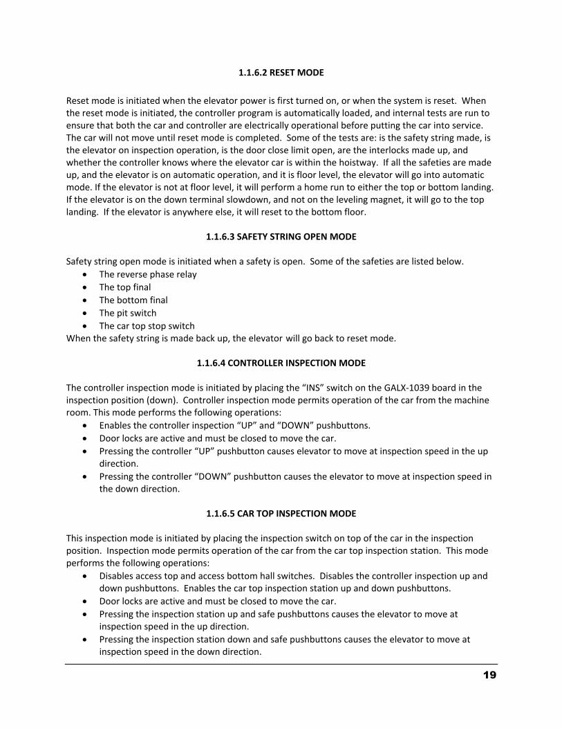
Reset mode is initiated when the elevator power is first turned on, or when the system is reset. When the reset mode is initiated, the controller program is automatically loaded, and internal tests are run to ensure that both the car and controller are electrically operational before putting the car into service. The car will not move until reset mode is completed. Some of the tests are: is the safety string made, is the elevator on inspection operation, is the door close limit open, are the interlocks made up, and whether the controller knows where the elevator car is within the hoistway. If all the safeties are made up, and the elevator is on automatic operation, and it is floor level, the elevator will go into automatic mode. If the elevator is not at floor level, it will perform a home run to either the top or bottom landing. If the elevator is on the down terminal slowdown, and not on the leveling magnet, it will go to the top landing. If the elevator is anywhere else, it will reset to the bottom floor.
1.1.6.3 SAFETY STRING OPEN MODE Safety string open mode is initiated when a safety is open. Some of the safeties are listed below.
The reverse phase relay
The top final
The bottom final
The pit switch
The car top stop switch When the safety string is made back up, the elevator will go back to reset mode.
1.1.6.4 CONTROLLER INSPECTION MODE The controller inspection mode is initiated by placing the “INS” switch on the GALX-1039 board in the inspection position (down). Controller inspection mode permits operation of the car from the machine room. This mode performs the following operations:
Enables the controller inspection “UP” and “DOWN” pushbuttons.
Door locks are active and must be closed to move the car.
Pressing the controller “UP” pushbutton causes elevator to move at inspection speed in the up direction.
Pressing the controller “DOWN” pushbutton causes the elevator to move at inspection speed in the down direction.
1.1.6.5 CAR TOP INSPECTION MODE
This inspection mode is initiated by placing the inspection switch on top of the car in the inspection position. Inspection mode permits operation of the car from the car top inspection station. This mode performs the following operations:
Disables access top and access bottom hall switches. Disables the controller inspection up and down pushbuttons. Enables the car top inspection station up and down pushbuttons.
Door locks are active and must be closed to move the car.
Pressing the inspection station up and safe pushbuttons causes the elevator to move at inspection speed in the up direction.
Pressing the inspection station down and safe pushbuttons causes the elevator to move at inspection speed in the down direction.

20
1.1.6.6 ACCESS MODE The access mode is initiated by placing the key operated access switch located in the car operating panel to the on position. Access mode allows entrance into the hoistway by qualified and authorized elevator maintenance personnel for equipment inspection and service. Access to the top of the car is possible from the top landing, and access to the pit is possible from the bottom landing. Enabling this mode permits the following operations:
Enables the access key switches at the top and bottom landing in the entrance door jambs.
Bypasses the gate switch to allow car movement with the car door open.
Bypasses the top or bottom landing hall door lock, depending on which terminal access switch is being keyed.
Turning the access key switch to the up position causes the elevator to move at inspection speed in the up direction.
Turning the access key switch to the down position causes the elevator to move at inspection speed in the down direction.
1.1.6.7 INDEPENDENT SERVICE MODE
The independent service mode is initiated by placing the key operated independent switch located in the car operating panel to the on position, or by placing the controller toggle switch “IND” to the down position. Independent mode permits operation of the car with an operator. This mode performs the following operations:
Hall initiated calls are ignored.
Hall lanterns and gongs are disabled.
The doors open automatically and stay open until closed by the operator.
Closing the doors requires constant pressure on the door close button. When the car door is closed, the car answers the nearest car initiated call in the direction of
travel.
1.1.6.8 ATTENDANT SERVICE MODE The attendant service mode is initiated by placing the key operated attendant switch located in the car operating panel to the on position. Attendant mode permits operation of the car with an attendant. This mode performs the following operations.
The doors open automatically and stay open until closed by the attendant.
Closing the doors requires a momentary pressure on the door close button, or the up or down buttons located in the car operating panel.
Hall initiated calls are answered unless there is constant pressure on the bypass button.
Hall lanterns and gongs are enabled.
The direction of preference can be specified by momentary pressure on the up or down buttons located in the car operating panel.
1.1.6.9 CODE BLUE HOSPITAL SERVICE MODE
Code blue hospital service mode is initiated by turning one of the code blue switches, located at each floor where medical emergency service is required, to the on position. A car is selected to respond to the code blue call. That car will perform the following:
21
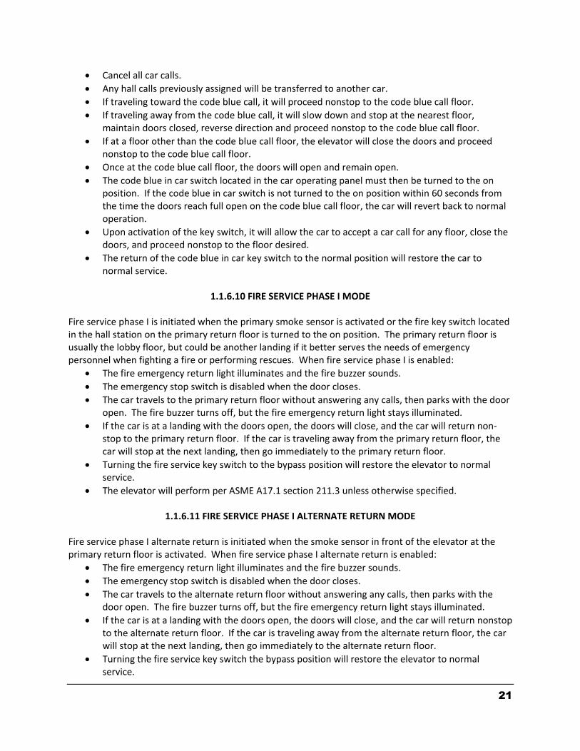
Cancel all car calls.
Any hall calls previously assigned will be transferred to another car.
If traveling toward the code blue call, it will proceed nonstop to the code blue call floor.
If traveling away from the code blue call, it will slow down and stop at the nearest floor, maintain doors closed, reverse direction and proceed nonstop to the code blue call floor.
If at a floor other than the code blue call floor, the elevator will close the doors and proceed nonstop to the code blue call floor.
Once at the code blue call floor, the doors will open and remain open.
The code blue in car switch located in the car operating panel must then be turned to the on position. If the code blue in car switch is not turned to the on position within 60 seconds from the time the doors reach full open on the code blue call floor, the car will revert back to normal operation.
Upon activation of the key switch, it will allow the car to accept a car call for any floor, close the doors, and proceed nonstop to the floor desired.
The return of the code blue in car key switch to the normal position will restore the car to normal service.
1.1.6.10 FIRE SERVICE PHASE I MODE
Fire service phase I is initiated when the primary smoke sensor is activated or the fire key switch located in the hall station on the primary return floor is turned to the on position. The primary return floor is usually the lobby floor, but could be another landing if it better serves the needs of emergency personnel when fighting a fire or performing rescues. When fire service phase I is enabled:
The fire emergency return light illuminates and the fire buzzer sounds.
The emergency stop switch is disabled when the door closes.
The car travels to the primary return floor without answering any calls, then parks with the door open. The fire buzzer turns off, but the fire emergency return light stays illuminated.
If the car is at a landing with the doors open, the doors will close, and the car will return non-stop to the primary return floor. If the car is traveling away from the primary return floor, the car will stop at the next landing, then go immediately to the primary return floor.
Turning the fire service key switch to the bypass position will restore the elevator to normal service.
The elevator will perform per ASME A17.1 section 211.3 unless otherwise specified.
1.1.6.11 FIRE SERVICE PHASE I ALTERNATE RETURN MODE Fire service phase I alternate return is initiated when the smoke sensor in front of the elevator at the primary return floor is activated. When fire service phase I alternate return is enabled:
The fire emergency return light illuminates and the fire buzzer sounds.
The emergency stop switch is disabled when the door closes.
The car travels to the alternate return floor without answering any calls, then parks with the door open. The fire buzzer turns off, but the fire emergency return light stays illuminated.
If the car is at a landing with the doors open, the doors will close, and the car will return nonstop to the alternate return floor. If the car is traveling away from the alternate return floor, the car will stop at the next landing, then go immediately to the alternate return floor.
Turning the fire service key switch the bypass position will restore the elevator to normal service.

22
The elevator will perform per ASME A17.1 section 211.3 unless otherwise specified.
1.1.6.12 FIRE SERVICE PHASE II MODE To initiate fire service phase II, the car must first have been placed in fire service phase I, and, as a result, be parked at the designated level with the door fully open. Following that, the key operated fire service phase II switch, located in the car operating panel must be placed in the on position. Fire service phase II permits operation of the car by a fire fighter. This mode performs operations in accordance with ASME A17.1 as follows:
The doors close only with constant pressure on the door close button, after they have been fully opened.
The doors open only with constant pressure on the door open button, after they have been fully closed.
Hall lanterns and gongs are disabled.
Safety edge and electric eye are disabled
All registered car calls can be canceled with momentary pressure on the call cancel button located in the car operating panel.
All hall calls are disabled.
To remove the car from fire service phase II the car must be at the fire return landing with the doors in the full open position and the phase II switch turned to the off position.
See ASME A17.1 for specific operation of fire service phase II.
1.1.6.13 EMERGENCY POWER Emergency power is initiated when a connection is made between terminals “HC” and “EMP”. This mode is used in buildings that have a backup power system to run at least one elevator in Automatic mode. Emergency power performs the following operations:
All cars are returned to the bottom floor one at a time, and remain there with their doors open.
If a car is selected to run it will go back into normal operation.
Removing the connection between terminals “HC” and “EMP” will remove the cars from emergency power operation.
1.1.6.14 EARTHQUAKE MODE
Earthquake mode is initiated upon activation of a seismic switch. This mode performs the following operations:
If in motion the car will proceed to the nearest available floor.
Open the doors and shut down.
23
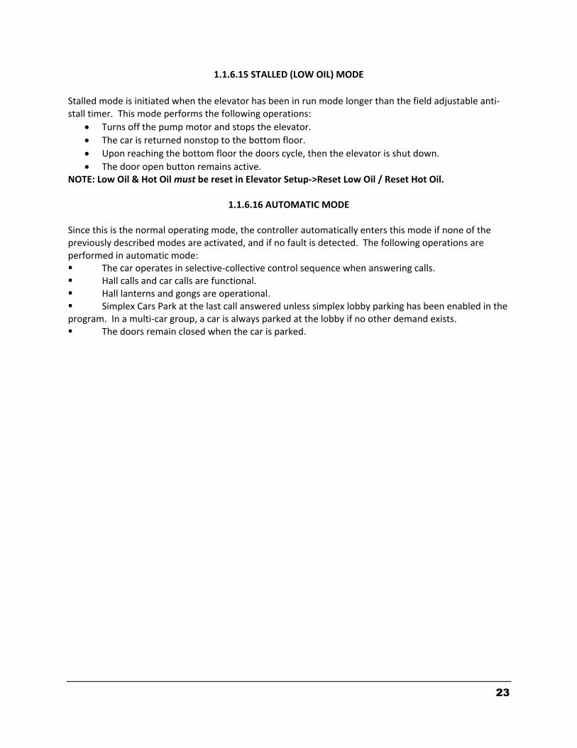
1.1.6.15 STALLED (LOW OIL) MODE
Stalled mode is initiated when the elevator has been in run mode longer than the field adjustable anti-stall timer. This mode performs the following operations:
Turns off the pump motor and stops the elevator.
The car is returned nonstop to the bottom floor.
Upon reaching the bottom floor the doors cycle, then the elevator is shut down.
The door open button remains active. NOTE: Low Oil & Hot Oil must be reset in Elevator Setup->Reset Low Oil / Reset Hot Oil.
1.1.6.16 AUTOMATIC MODE Since this is the normal operating mode, the controller automatically enters this mode if none of the previously described modes are activated, and if no fault is detected. The following operations are performed in automatic mode: The car operates in selective-collective control sequence when answering calls. Hall calls and car calls are functional. Hall lanterns and gongs are operational. Simplex Cars Park at the last call answered unless simplex lobby parking has been enabled in the program. In a multi-car group, a car is always parked at the lobby if no other demand exists. The doors remain closed when the car is parked.
24
SECTION – 2 INSTALLATION OF THE GALaxy CONTROLLER
2.1 GENERAL INFORMATION This section provides basic guidelines and recommendations for the proper installation of the controller equipment. These guidelines should be used as general instructions. They are not intended to usurp local codes and regulations.
2.2 SITE SELECTION When choosing the installation site of the controller, several factors should be considered. If at all possible, the controller should be installed in a location where the mechanic has a good view of the machine when he is standing in front of the controller. There should be no obstructions around the controller that would prevent proper routing of necessary conduits entering the controller. The controller doors should have enough room to fully open and close. All clearances, working space, lighting, and guarding should comply with governing codes.
2.3 ENVIRONMENTAL CONSIDERATIONS The standard controller package is provided with a NEMA 1 enclosure. This type of controller should be installed in a clean and dry environment. Ideally, the equipment room should be temperature controlled between 70 and 90 degrees F. However, control equipment will function properly within an ambient temperature range of 35 to 110 degrees F. If temperatures remain at the upper and lower extremes of this range for an extended period of time, the life expectancy of the control equipment may be shortened. If wet, dusty, or corrosive environments are expected, then optional non-standard enclosures can be provided, i.e. NEMA 4, NEMA 12, or NEMA 4X. The control system is designed to have a high immunity to electrical noise, radio frequency radiation, and magnetic interference. However, high levels of these items could cause interference with certain parts of the control system. The power supply feeding the controller should have a fluctuation of no greater than + or - 10%.
2.4 WIRING GUIDELINES AND INSTRUCTIONS
2.4.1 THE WIRING PRINTS Each set of wiring schematics is job specific. The job name and number will be listed in the bottom right corner of each page of the print. A separate binder will be provided for each job containing a complete set of wiring schematics.
2.4.2 GROUND WIRING Proper grounding of the power supply, controller, elevator car, and hoistway is required. Separate conductors should be run for “EG” (earth ground) and “GND” terminals. These terminals and
25
conductors are detailed on the wiring schematics.
2.4.3 HOISTWAY WIRING All hoistway wiring is detailed on the wiring schematics. The number of hoistway conductors is calculated and listed per job on the wiring schematics. A job specific “pull sheet” is also provided with the wiring schematics.
2.4.4 ELEVATOR CAR WIRING All elevator car wiring is detailed on the wiring schematics. The number of traveling cable conductors is calculated and listed per job on the wiring schematics. A job specific “pull sheet” is also provided with the wiring schematics.
2.4.5 MACHINE ROOM WIRING All machine room wiring is detailed on the wiring schematics. All wire sizes are listed for main power supply, motor wiring, brake wiring (traction only), and field wiring.
2.4.6 WIRING TO TOP OF CAR SELECTOR The car top selector is wired according to the schematics for the job. However, special attention should be given to wiring the pulse sensor on the selector since the output on this device uses +15VDC. Terminal PPS on the selector is wired to PPS on the controller and selector terminal PP/US is wired to PP on the controller. Note that since the PP/US output on the selector cannot work for both PP and US at the same time, the US and DS functions are wired from USF and DSF on the selector to US and DS respectively on the controller.
2.4.7 SLOWDOWN LIMIT SWITCHES There are two types of slowdown inputs used “UT & DT” and “UTS & DTS”. Slowdown switches “UT and DT” are used to open the “ON” command to the high-speed valve at the terminal landings independent of the control of the CPU. The “UTS & DTS” limit switches are used as slowdown speed verification points by the Safety Processor board. If the car hits the velocity verification point at a speed greater than the preset speed, power is immediately removed from the pump motor and the motion valves are de-energized for an emergency stop. The “UT & DT” limit switches are also used as speed verification points by the Safety Processor board. When the limit is first hit, the Safety Processor counts an adjustable number of pulse counts from that point to determine the velocity trip point. Since cars with only one slowdown limit would hit the limit at high speed when recovering from being lost, the extra pulse counts from the limit allows the car to slow down before the trip point is reached. The Safety Processor board uses the “UT & DT” limits to verify the operation of the “UTS & DTS” limits. The pulse input is also verified while running on automatic. The distance that the limits are placed from the terminal landing depends on the speed of the car. On the next page, Table 2.0 shows the slowdown limit locations with respect to contract speed. All
26
distances are shown in inches.
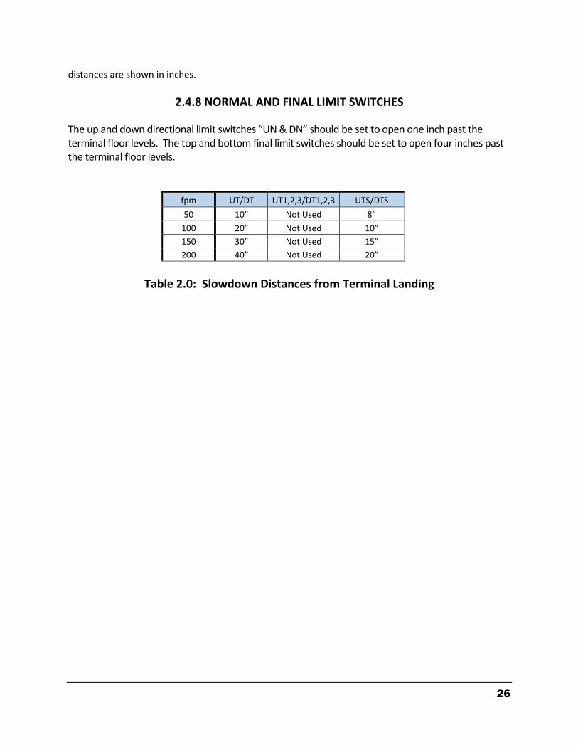
2.4.8 NORMAL AND FINAL LIMIT SWITCHES
The up and down directional limit switches “UN & DN” should be set to open one inch past the terminal floor levels. The top and bottom final limit switches should be set to open four inches past the terminal floor levels.
fpm UT/DT UT1,2,3/DT1,2,3 UTS/DTS
50 10” Not Used 8”
100 20” Not Used 10”
150 30” Not Used 15”
200 40” Not Used 20”
Table 2.0: Slowdown Distances from Terminal Landing

27
Section 3 - ADJUSTMENT OF THE GALaxy HYDRAULIC CONTROLLER
3.1 GENERAL INFORMATION Before adjustment begins the following items must be completed. 1. All field wiring and safety circuits installed 2. Temporary jumpers from terminal “HC” to terminals “MES & ALT” 3. All hoistway limit switches installed 4. All car and hoistway doors and interlocks installed and pre-adjusted 5. Selector installed and magnets pre-adjusted 6. Valve pre-adjusted. 7. Familiarize yourself with all wiring schematics
3.1 INITIAL POWER-UP
3.1.1 CHECK MAIN-LINE VOLTAGE
With main-line disconnect in the off position, check the line-side voltage with a voltmeter to ensure the voltage matches the controller name tag “Input Power” voltage. Check to ensure all three phases are present. If voltage is incorrect or all three phases are not present, do not proceed until corrected. If voltage and phases are correct, proceed to the next step: 3.2.2 SET TOGGLE SWITCHES.
3.1.2 SET TOGGLE SWITCHES
Flip all toggle switches on the GALX-1039 board down except for the car gate bypass and the door lock bypass switches. Flip those two switches up.
3.1.3 MAKE SURE THE CAR IS SAFE
Verify that all elevator doors are closed and that all safety circuits are functional.
3.1.4 CHECK CONTROLLER VOLTAGE
Turn the main-line disconnect to the on position. Check voltage at fuses L1, L2, and L3 (if present) on controller. If correct, check voltage at terminal “LIN” with respect to “GND”. Voltage should read 120VAC. If correct, check voltage at terminals “S10, LC, & HC” with respect to “GND”. All should read 120VAC. If not, check wiring diagram to determine problem before continuing.

28
3.1.5 VERIFY THE LCD GALaxy IS BLINKING
Check to make sure that the “axy” of GALaxy on the LCD is blinking. If the “axy” is blinking, continue to the next step. If not, check voltage at terminals 5V to 0V on the GALX-1039 board to ensure 5VDC. If 5VDC is present and the “axy” on the LCD is not blinking, then contact factory.
3.1.6 PRESET ADJUSTABLE VARIABLES ON SAFETY PROCESSOR BOARD
The safety processor (GALX-1066N) board is normally preset prior to leaving the factory. However, it is prudent to check the setup values for the proper settings. Refer to section 6 of this manual for the operation of the safety processor board LCD interface. The following adjustment variables must be set properly:
Top Spd (contract speed) Enc RPM (Not Used) Enc PPR (Not Used) Fdbk Typ (0=tape, 1=enc) Ctrl Typ (0 = Hydro) 2 Stop (0=Mult, 1=2 stop) RearDoor (0=Front only, 1=Rear) UTS Vel (Set to top speed) DTS Vel (Set to top speed) INS Vel (Set to 140) LEV Vel (Set to 140) UT Vel (Set to top speed) DT Vel (Set to top speed) UL Count (Set to 12, 16 counts/ft.) DL Count (Set to 12, 16 counts/ft.) Dmd Mult (Not used) SoftStop (Set higher than the soft stop time on the main CPU)
Note that the velocity variables will be changed once the car is running on automatic.
3.1.7 PLACE STOP SWICTH IN RUN POSITION
Flip the “STOP” toggle switch on the GALX-1039 board to the up position. Verify that input LEDs for “LC, HC, DN, UN, SS and CS” are all on. If not, then correct field wiring.
3.1.8 PUMP MOTOR ROTATION
To check for proper rotation of pump motor, press the inspection “UP” push-button on the GALX-1039 board just long enough for the motor to begin turning. If rotation is correct, continue to the next step. If rotation is wrong, then swap any two of the three legs feeding
29
terminals “L1, L2, & L3" on the “DEL” contactor. Check to ensure rotation is correct and then continue.
3.1.9 READY TO RUN ON INSPECTION
The car should be ready to run on inspection if all terminals are wired correctly. Select the “Elevator Status” on the main CPU board LCD. The display should show “Out of Service” on the first line and “Inspection Mode” on the second. The LCD on the Safety Processor Board will display one of the following types of inspection:
“MR INS” (Motor Room) “CT INS” (Car Top) “ACCESS” (Access) “IC INS” (In Car) “AUTO” (Not on Inspection)
To run the car from the motor room, “MR INS” should be displayed on the Safety Processor.
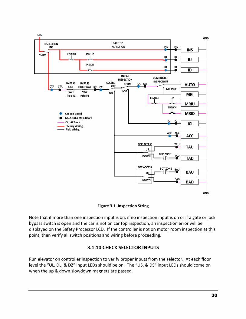
The “inspection string” consists of contacts from the inspection switches and the gate and lock bypass switches in series. One and only one of the five inspection inputs should be on for the car to run. Starting from the car top inspection input, the five inspection inputs are, “INS” for car top, “ACC” for access, “ICI” for in-car, “MRI” for motor room, and “AUTO” for automatic (not on inspection).
30
INS
IU
ID
AUTO
MRI
MRIU
MRID
ACC
TAU
TAD
BAU
BAD
INS INS
IU IU
ID ID
INS
INS UP
INS DN
ENABLE
INSPECTION
NORM
CTA CTABYPASS
CARBYPASS
HOISTWAY
SW1Pole #1
SW2Pole #1
ICC ICC
ACCESSOFF
ON
ICA ICA
CONTROLLERINSPECTION
ENABLE UP
DOWN
ACC ACC
TAU
TAD
BAU
BAD
BOT ZONE
TOP ZONE
TOP ACCESS
BOT ACCESS
UP
UP
DOWN
DOWN
GND
GNDCTS
ICIICI ICI
NORM
INSP
IN CARINSPECTION
CAR TOP INSPECTION
MR INSP
Car Top Board
GALX-1064 Main Board
Circuit TraceFactory WiringField Wiring
Figure 3.1. Inspection String
Note that if more than one inspection input is on, if no inspection input is on or if a gate or lock bypass switch is open and the car is not on car top inspection, an inspection error will be displayed on the Safety Processor LCD. If the controller is not on motor room inspection at this point, then verify all switch positions and wiring before proceeding.
3.1.10 CHECK SELECTOR INPUTS
Run elevator on controller inspection to verify proper inputs from the selector. At each floor level the “UL, DL, & DZ” input LEDs should be on. The “US, & DS” input LEDs should come on when the up & down slowdown magnets are passed.
31
3.1.11 VERIFY SLOWDOWN LIMITS As the car is running verify that the up and down slowdown sensors for each floor, “US and DS”, activate prior to reaching the landing. Also verify that the up and down terminal slowdown limits inputs “UT, UTS, DT & DTS” are breaking at the proper distances as shown in the slowdown table 2.0. “US and DS” turn on when active but “UT, UTS, DT & DTS” turn off when active. “UT & DT” should turn off one inch closer to the terminal floor levels than when the “US & DS” inputs turn on.
3.1.12 VERIFY CAR SPEED ON SAFETY PROCESSOR BOARD Run the car in either direction and check the car speed on the safety processor LCD. The speed shown should match the car’s speed actual speed. If the speed does not match and the secondary feedback comes from pulses from the tape go to “Correct Car Speed When Using a Tape”. If the secondary feedback comes from an encoder go to “Correct Car Speed When Using an Encoder”. If the correct speed is shown proceed to the “Final Adjustment” section.
3.1.13 CORRECT CAR SPEED WHEN USING A TAPE The tape has holes every 3/8” that are 3/8” in diameter. The safety processor measures the time between each pulse to calculate the velocity. If the velocity is not displayed correctly first make sure that the feedback type in the safety processor board adjustable variable is set to 0 for a tape application. Next, while the car is running, make sure that the PULSE INDICATION LED on this board is pulsing. As the car increases in speed the LED will glow solid “on”. If the LED does not pulse, try swapping the wires at the PPS and PP terminals. If the LED still does not work, contact the factory. If the correct speed is shown proceed to “Final Adjustment”.
3.1.14 CORRECT CAR SPEED WHEN USING AN ENCODER When using an encoder for the secondary speed feedback, make sure that the adjustable variables on the safety processor board are set properly. Set the feedback type to 1 for encoder and set the encoder RPM and PPR appropriately for how the encoder is driven. If the correct velocity is not obtained, contact the factory. If the correct speed is shown proceed to the next step.
32
3.2 FINAL ADJUSTMENT
3.2.1 AUTOMATIC RUN
Run the elevator on controller inspection down until it stops on the down normal limit switch. All toggle switches on the GALX-1039 board should still be in the down position except the “STOP” toggle switch, which should be in the up position. The valve should be pre-adjusted to provide the quickest transitions possible and leveling speeds at approximately 5 to 6 fpm. With the elevator on controller inspection and on the down normal limit switch, flip the “INS” toggle switch to the up position. If all is correct, the elevator should level up to floor level at the bottom floor. If elevator does level up and stop at the bottom floor then proceed to the next step. If the elevator does not level up to the floor then verify that the “INS” input LED is on. If “INS” input LED is on, and the elevator does not level up, then check the selector and limit switches verifying proper input signals back to the controller.
3.2.2 SET FLOOR DEAD ZONE The elevator should now be at floor level at the bottom floor. When at floor level the “UL, DL, & DZ” input LEDs should be on. If elevator continually tries to seek floor level by leveling up and down, then adjust valve and selector “dead zone” for proper stop. The selector “dead zone” is increased by moving the selector sensor boards closer together. Proceed to the next step.
3.2.3 ADJUST VALVE Setup a car call, either from the LCD Interface or from simulating a pushbutton with jumper wire. The elevator should start up, accelerate to high speed, decelerate when slowdown point is reached, and level into floor. The doors will not open because toggle switches “IND & AD” are still in the down position. Continue to run elevator by setting up car calls. Adjust valve for smooth accel, decel, and final stop in both up and down directions. Proceed to the next step.
3.2.4 ADJUST SAFETY PROCESSOR BOARD SPEED CLAMPS Make a one floor run to the top floor. The car must reach top speed on a one floor run. After the car stops, record the velocity the car hit the “UT, DT, UTS & DTS” slowdown limits. The velocity value is shown from the LIM VEL menu on the safety processor board LCD. The velocity value shown on the display for the “UT or DT” limit is the value after the car hits the limit then counts the adjustable number of counts set from “UT Count” or “DT Count”. When using a tape feedback, there are 16 pulse counts per foot or 1.333 pulses per inch. If the

33
limit is set to 40” from the terminal, to set the checkpoint at 20” use a count value of 26.6 (20 * 1.333). Round up and set the UT and DT count to 27. If the UT or DT Counts are modified, the limit velocity has to be rechecked. Make a one floor run to the bottom floor and record the limit velocity when the car stops. Take the speed value for the up or down terminal slowdown limit, add 15 fpm and then set the new value in the corresponding variable from the ADJ VAR menu.
3.2.5 VERIFY INSPECTION VELOCITY CLAMP ON SAFETY PROCESSOR BOARD With the car on inspection, set the inspection speed on the safety processor board to 25 fpm (Refer to Safety Processor Adjustable Variables in section 6). Set the inspection speed on the main CPU to 50 fpm (Refer to Adjustable Variables in section 5). Run the car in either direction on inspection. The car will shut down when the speed goes above 25 fpm. Reset the inspection speed on main CPU to the desired inspection speed and set the inspection speed on the Safety Processor to 140 fpm or lower. Make sure the car will run on inspection without shutting down.
3.2.6 ENABLE DOORS Before proceeding re-check all safety circuits and door lock circuits for proper operation. If all safety circuits and door locks are operating properly then flip the “AD” toggle switch to the up position, and the doors should open and remain open. The elevator is now on independent service. If the doors do not open, then check door operator wiring. Adjust door operator for proper operation. Proceed to the next step.
3.2.7 FINE TUNE RIDE AND STOPS Run elevator to all floors. “Fine tune” all floor level magnets so that elevator stops level at all floors. Check all signals for proper operation. Flip the “IND” toggle switch to the up position. All four toggle switches should now be in the up position. Elevator doors should close and now be in full automatic operation. Check all hall buttons for proper operation. Proceed to the next step.
3.2.8 FINE TUNE PARAMETERS Check all field adjustable parameters from the LCD Interface and set as desired.
34
Section 4 - TROUBLESHOOTING
4.1 GENERAL INFORMATION The GALaxy controller is equipped with a number of features that aid in troubleshooting any problems that may occur. The physical layout of the controller provides ready access to all I/O in order to make voltage measurements. All inputs have LEDs to monitor the state of the input. The controller is also equipped with an LCD interface discussed in sections 5, and an LCD interface on the Safety Processor Board discussed in section 6. In this section the basic points of troubleshooting will be detailed.
4.2 MICROPROCESSOR CPU The CPU is very reliable and normally trouble-free. With power turned on, the “axy” in GALaxy on the LCD interface should be blinking at one second intervals to indicate that the CPU is running. If it is not blinking, then check voltage at the 5V terminal with respect to the 0V terminal on the GALX-1039 board. This voltage should read 5VDC. If not, then check the input and output voltage of the DC power supply. If the “axy” is not blinking and 5VDC is present at the 5V terminal with respect to the 0V terminal, then contact the factory. All job parameters that are not field adjustable are stored in FLASH memory. All job parameters that are field adjustable are stored in battery backed-up RAM. This battery is designed to back-up the RAM for one year with no power to the system. Under normal operating and maintenance procedures, the battery should last indefinitely. If, however, a battery were to go bad, the field adjustable parameters will return to the default settings when the main power is turned off.
4.3 INPUT/OUTPUT BOARDS The two main sections of all the I/O boards are the low voltage and the high voltage sections. The low voltage section consists of all the digital interfacing necessary for the CPU to communicate with the field components. The high voltage section consists of the field components (buttons, switches, lights, relays and sensors) and their associated input and output signals. The standard voltage for all I/O is 120VAC. However, if necessary, the I/O boards can accept a voltage range from 24V to 120V AC or DC. It is very important that the wiring schematics are reviewed in order to determine the voltages for which the controller was designed before power is applied. The majority of problems that may arise with the control system are due to faulty inputs or outputs on the high voltage side of the system. For example, having a limit switch not feeding or an acknowledgment light out. The GALaxy control system is designed to enable the technician to check both the high voltage section and the low voltage section to correct the problem. The high voltage section is checked with a digital voltmeter or with the individual LEDs that are associated with each input. Depending on the particular input or output, the voltage measured at the terminal will either be “high” or “low” with respect to its reference point. For example, to determine whether or not the up terminal slowdown limit switch was feeding, the voltage should be measured at terminal “UT” with respect to “GND”. If the switch is feeding it should read 120VAC. If the switch is open, the voltage should read less than 50VAC. Another means by which to determine whether the switch is feeding is to view the “UT” input LED. If the LED is on, the switch is feeding. If the LED is off,

35
the switch is open. The previous example determines whether or not the field component is functioning properly. However, to determine if the signal is actually being communicated to the CPU the signal must be checked on the low voltage section of the board. The low voltage section is checked from the LCD interface. Using the previous example, select the “Inputs and Outputs” menu on the LCD interface. Scroll through the I/O list until “UT” is located. It will show “UT=1” if the “UT” switch is feeding and “UT=0” if the switch is open. A second example will show how to determine if an output is working properly. With the car at the first floor and the controller designed for 120VAC discrete position indicators, the “P1” output should be on. The voltage measured at terminal “P1” with respect to “GND”, should read 120VAC. If the voltage reads less than 50VAC, the voltage supplied to the output device must be checked. The schematic, in this case, would show the “P1” voltage is supplied at the “PIC” terminal. A voltmeter would be used to measure the voltage between “PIC” and “GND”. If that voltage is at the terminal but the indicator is not on. The LCD interface could be used to view if the CPU is turning the “P1” output on. From the LCD “Inputs and Outputs” menu, scroll through the I/O list until the “P1” is located. The display will show “P1=1” to turn on the “P1” output. For this example, since the CPU is turning on the output and the correct voltage is at the output common but not at the output terminal, it would indicate that the output solid-state relay for “P1” is defective and should be replaced. All of the I/Os are optically isolated between the high voltage section and the low voltage section. The input opto-isolators and output solid-state relays are socketed ICs labeled “Uxx” on the silk screens of the different I/O boards. If it is determined through the previous troubleshooting procedures that the input signal is present at the terminal, but is not being communicated to the CPU, the input opto-isolator may be defective and can be replaced in the field. If it is determined that the CPU is communicating the output signal to the solid-state relay, but the voltage does not go high at the terminal, the solid-state relay may be defective and can be replaced in the field. Any time ICs are replaced, the power should be turned off and care should be taken in removal of the old chip and replacement of the new one. All of the I/O and their associated ICs are listed in the wiring schematics.

36
4.4 RUN SEQUENCE The following diagram in figure 4.1 shows the run sequence of the controller.
Figure 4.1: Run Sequence.
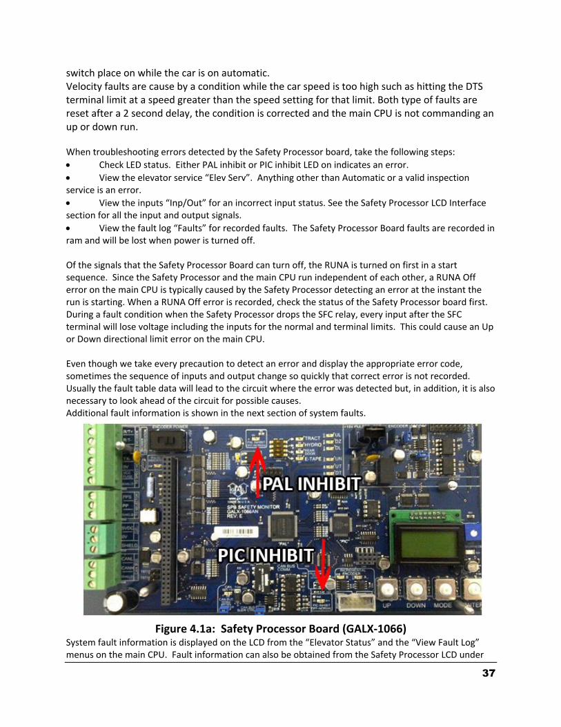
4.5 THE SAFETY PROCESSOR BOARD
The Safety Processor Board has two fault LEDs, one on the top center and one on the bottom center of the board. The top center LED is for PAL Inhibit and the bottom center one is for PIC Inhibit (see Figure 4.1a).
Important: When either LED is on, this board will prevent the car from running.
The Safety Processor Board verifies the speed of the car when hitting the terminal limits, that the doors are closed when they should be and that the car is safe to run. It also verifies all inspection operations and that the car is not traveling at a speed greater than 150 fpm with a door open in the door zone.
While the Safety Processor Board cannot turn on any run control signals, it can turn off the following signals from the main CPU: RUNA, UP, DNR, UPF and DF. The SFC relay in the safety string is also controlled by the Safety Processor Board.
The Safety Processor board detects two types of faults, active faults and velocity faults. Active faults are input conditions that are considered as unsafe or an error such as the lock bypass
37
switch place on while the car is on automatic. Velocity faults are cause by a condition while the car speed is too high such as hitting the DTS terminal limit at a speed greater than the speed setting for that limit. Both type of faults are reset after a 2 second delay, the condition is corrected and the main CPU is not commanding an up or down run. When troubleshooting errors detected by the Safety Processor board, take the following steps:
Check LED status. Either PAL inhibit or PIC inhibit LED on indicates an error.
View the elevator service “Elev Serv”. Anything other than Automatic or a valid inspection service is an error.
View the inputs “Inp/Out” for an incorrect input status. See the Safety Processor LCD Interface section for all the input and output signals.
View the fault log “Faults” for recorded faults. The Safety Processor Board faults are recorded in ram and will be lost when power is turned off. Of the signals that the Safety Processor Board can turn off, the RUNA is turned on first in a start sequence. Since the Safety Processor and the main CPU run independent of each other, a RUNA Off error on the main CPU is typically caused by the Safety Processor detecting an error at the instant the run is starting. When a RUNA Off error is recorded, check the status of the Safety Processor board first. During a fault condition when the Safety Processor drops the SFC relay, every input after the SFC terminal will lose voltage including the inputs for the normal and terminal limits. This could cause an Up or Down directional limit error on the main CPU. Even though we take every precaution to detect an error and display the appropriate error code, sometimes the sequence of inputs and output change so quickly that correct error is not recorded. Usually the fault table data will lead to the circuit where the error was detected but, in addition, it is also necessary to look ahead of the circuit for possible causes. Additional fault information is shown in the next section of system faults.
Figure 4.1a: Safety Processor Board (GALX-1066) System fault information is displayed on the LCD from the “Elevator Status” and the “View Fault Log” menus on the main CPU. Fault information can also be obtained from the Safety Processor LCD under

38
the “Fault” menu. Below is a list of system faults logged by the main CPU and possible reasons for each fault.
4.6 MAIN CPU FAULTS
Faults Description Possible Cause/Suggested Fix
ASV Time-out Car 1
Automatic Service Time-out Car 1
• Car was not able to answer group hall call within the automatic service time-out timer. Look for fault condition on car.
ASV Time-out Car 2
Automatic Service Time-out Car 2
• Car was not able to answer group hall call within the automatic service time-out timer. Look for fault condition on car.
At Floor Shutdown
At floor shutdown • Car faulted out while at floor. Look at the fault log for a different fault at the same time to determine cause of failure.
Binary Input Fault The floor position, read from binary inputs on the selector, does not match the car position.
• Excessive wear on the selector guides. • Preset magnet is missing or misaligned. • Faulty Hall Effect sensor on sensor board. • Faulty output on selector driver board. • Faulty BP1, BP2 or BP4 input • Improper wiring between selector and the Top of Car board.
Bot Door Lock Fault
The Bottom Door Lock failed on while the door was open.
Faulty door lock. • Door lock not adjusted properly. • Jumper placed on door lock circuit. • Faulty wiring to DLB input. • Faulty DLB and DLB-1 inputs (For this to occur both DLB and DLB-1 inputs must fail on). • DOL input failed. Replace DOL input chip. • Door operator open limit DOL is not adjusted properly
Car 1 Comm Loss The group car is not communicating with Car 1.
• Faulty wiring from R/T+ and R/T- from car to car. • Faulty U6 driver chip on 1100 board or 1036 com memory board. • Noise on shield wire. Connect shield only on one end. • Noise on the communication wires. Run wires in separate conduit.
Car 2 Comm Loss The group car is not communicating with Car 2.
• Faulty wiring from R/T+ and R/T- from car to car. • Faulty U6 driver chip on 1100 board or 1036 com memory board. • Noise on shield wire. Connect shield only on one end. • Noise on the communication wires. Run wires in separate conduit.
Car Safe Fault
The Car Safe Fault occurs from the wanting to run but does not have a critical input energized. Some of the conditions for a car safe fault will also cause other faults to be logged.
• The car does not have the gate or lock inputs and is running or trying to run • The stop switch is open • An inspection string input fault. Only one input should be on in the inspection string (AUTO, CTI, ICI, ACC or MRI) • Gate or Lock Bypass switch is on when not on car top inspection

39
Faults Description Possible Cause/Suggested Fix
Car Safe Fault Preop
The car had a car safe fault while pre-opening the door.
• The car lost the DZ input while leveling into the floor and the door was open.
Car Safe Fault Start
The car had an onward call, had the door close limit but the car gate or door locks did not make after a 3 second time-out.
• The locks are not making properly when the door closes. • The door is not closing properly.
Delta off Fault DEL input did not come on at start or went off during a run.
• The delta contact did not make on a Y-Delta starter. • The MC contact did not make on an across-the-line starter • The 'at speed' contact did not make on an electronic soft-starter. • Faulty DEL input. Replace the DEL input chip.
Delta On Fault
DEL input failed on when is should have been off. This would occur at the start of a run when the I/Os are checked. The input failed on or the contact for the input failed closed.
• Faulty DEL input (failed on). Check the input and output status on the LCD interface. • Faulty contact for DEL input failed on. Replace the DEL input chip.
DF I/O Failed Off The DF (SDF) input or output has failed off
• Fault on Safety Processor Board. The Safety Processor Board can disable the run control to the DF (SDF) output chip. Check if the PIC or PAL inhibit LED turns on when the car attempts to run. Check the elevator service, faults, and inputs/outputs on the Safety Processor Board LCD. • Faulty wiring to the SC common on the MAIN I/O board. • Faulty wiring to the SDF terminal on the MAIN I/O board. • Faulty wiring to the Down Fast valve. • Faulty DFi (SDFi) input (replace input chip). • Faulty DF (SDF) output (replace output chip).
DF I/O Failed On The DF (SDF) input or output has failed on.
• Faulty DFi (SDFi) input (replace input chip). • Faulty DF (SDF) output (replace output chip).
DL Failed On Fault DL Failed On Fault. The DL leveling sensor did not turn off during a run.
• DL hall effect sensor bad on selector sensor board. Replace sensor board. • DL Output Driver failed on. Replace output on selector driver board. • DL traveling cable wire is shorted to 120 VAC. Remove input wire to 1038 or 1064 board and verify that LED goes out. Correct short condition. • DL inputs failed on. Short on 1038 or 1064 main I/O board. Replace main I/O board.
DLB & DLB-1 Opposite
Input failure on one of the Door Lock Bottom (DLB) inputs.
• Faulty DLB or DLB-1 input (replace input chip).
DLM & DLM-1 Opposite
Input failure on one of the Door Lock Middle (DLM) inputs.
• Faulty DLM or DLM-1 input (replace input chip).
DLT & DLT-1 Opposite
Input failure on one of the Door Lock Top (DLT) inputs.
• Faulty DLT or DLT-1 input (replace input chip).
Dn Directional Fault
Car unexpectedly hit the Down Normal Limit while running down.
• Faulty wiring for the DN limit. • The power common to the limit switches (CS) was lost. Check safety string prior to the CS terminal.

40
Faults Description Possible Cause/Suggested Fix
DNR I/O Failed Off
The DNR (SD) input or output has failed off.
• Fault on Safety Processor. The Safety Processor is located on the MAIN I/O board. This device can disable the run control to the DNR output chip. Check if the SAF-PROC or SAF-PAL FAULT LEDs turn on when the car attempts to run. Check the elevator service, faults, and inputs/outputs on the Safety Processor status of the LCD Interface. • Faulty wiring to the SC common on the MAIN I/O board. • Faulty wiring to the SD terminal on the MAIN I/O board. • Faulty wiring to the Down valve. • Faulty DNR (SD) output or DNRi (SDi) input. Replace the DNR (SD) output and DNRi (SDi) input chip. • RUN outputs or MC auxiliary contact not making properly. Verify the operation and contact integrity.
DNR I/O Failed On The DNR (SD) input or output has failed on.
• Faulty DNR (SD) output. Replace the DNR (SD) output chip. • Faulty DNRi (SDi) input. Replace DNRi (SDi) input chip.
Door Close Fault The door did not reach the Door Close Limit within the door close protection time.
• Door Close Limit (DCL) not adjusted properly. • Faulty Door Close Limit (DCL). Replace DCL input chip. • Trash in door track preventing door from closing.
Door Open Fault The door did not reach the Door Open Limit within the door open protection time.
• Door Open Limit (DOL) not adjusted properly. • Faulty Door Open Limit (DOL). Replace DOL input chip.
Door Zone Aux On Flt
The auxiliary door zone input failed on.
• DZA output on selector board failed on. (Replace DZA output on selector driver board). • One or both of the DZA sensors on the selector sensor board failed. Replace selector sensor board. • DZA input on the Main I/O board failed. Replace DZA input on the Main I/O board.
Door Zone Off Fault
The door zone input failed off.
• DZ output on selector board did not turn on. (Replace DZ output on selector driver board). • One or both of the DZ sensors on the selector sensor board failed. Replace selector sensor board. • DZ input on the Main I/O board failed. Replace DZ input on the Main I/O board.
Door Zone On Fault
The door zone input failed on.
• DZ output on selector board did not turn off. (Replace DZ output on selector driver board). • One or both of the DZ sensors on the selector sensor board failed. Replace selector sensor board. • DZA input on the Main I/O board failed. Replace DZA input on the Main I/O board.
DoorZone Aux Off Flt
The auxiliary door zone input failed off.
• DZA output on selector board did not turn on. (Replace DZA output on selector driver board). • One or both of the DZA sensors on the selector sensor board failed. Replace selector sensor board. • DZA input on the Main I/O board failed. Replace DZA input on the Main I/O board.
41
Faults Description Possible Cause/Suggested Fix
DPM Input Fault The DPM input fault occurs when door opens and the DPM input did not go off.
• DPM switch not setup properly on the door operator. • Faulty DPM input. Replace DPM input chip.
DPM Off/GS or DL On
DPM Off with Gate Switch or Door Lock On. The Door Protection Module input must go on before gate switch or door lock inputs go on.
• The DPM switch on the door operator is not setup properly. DPM should turn on before the Gate Switch is made. • There is no DPM input on the door operator. Jump the DPM input to the GS-1 terminal. • Fault DPM input. Replace the DPM input chip.
DT Failed On Fault
DT input Failed On Fault. The car was at the bottom floor and the DTS input was low true (DTS switch made) but the DT input was high (DT not made).
• The DTS switch is not wired or the DTS switch is not used. If the DTS switch is not used, jump the DT and DTS inputs together. • The DT did not break at the bottom terminal landing. Adjust or replace the DT switch. • Faulty DT input. Replace the DT input chip.
DTS Failed On Fault
DTS input Failed On Fault. The car was at the bottom floor and the DT input was low true (DT switch made) but the DTS input was high (DTS not made).
• The DT switch is not wired or DT input was lost. The state of DT is compared to that of DTS. • The DTS limit did not break at the bottom terminal landing. Adjust the DTS magnet. • Faulty DTS input. Replace the DTS input chip on the Main I/O board.
Emergency Exit Flt
An emergency stop occurred while moving.
• The Safety string opened while the car was running. Check the safety circuit. • The LC input is off. Check the LC fuse. If the LC fuse is blown check for short from LC to GND.
Estop Fault An emergency stop occurred while moving or attempting to move.
The 'P' input did not drop from MC contactor being energized. • The stop switch was pulled while running. • The car was not safe usually from clipping a door lock. See Car Safe Fault. • The stall protection timer timed-out. • An emergency power recall was initiated while the car was running up. • The pulse count stopped counting
Field Vars Deflt Ini
Field Variables Default Initialization. Field adjustable variables are being initialized for the first time.
• Job related parameters are invalid. This error occurs on the first time the 1036 board is being powered up.
Field Vars Relocated
Field Variables Relocated.
The software has been updated to a newer version that required parameters to be relocated. This is normal and should only occur once. If an older version software is later installed, the job parameters may be lost.
Fire Fighter Stop Sw
Fire Fighter Stop Sw • Fire Fighter Stop switch is pulled. • Faulty wire connection in the Fire Fighter stop switch circuit.
FST I/O Failed Off The FST input on the Main I/O board did not pick up when expected.
• Faulty FST output chip. Replace output chip. • Faulty FSTI input chip. Replace input chip.
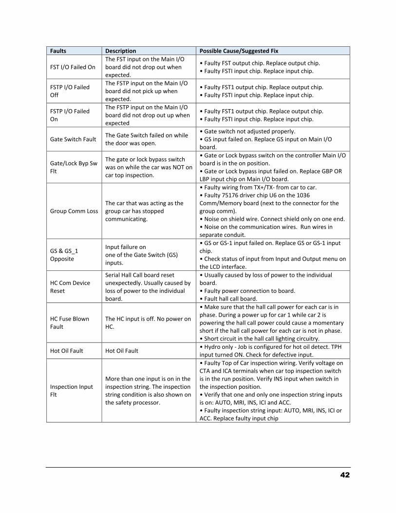
42
Faults Description Possible Cause/Suggested Fix
FST I/O Failed On The FST input on the Main I/O board did not drop out when expected.
• Faulty FST output chip. Replace output chip. • Faulty FSTI input chip. Replace input chip.
FSTP I/O Failed Off
The FSTP input on the Main I/O board did not pick up when expected.
• Faulty FST1 output chip. Replace output chip. • Faulty FSTI input chip. Replace input chip.
FSTP I/O Failed On
The FSTP input on the Main I/O board did not drop out up when expected
• Faulty FST1 output chip. Replace output chip. • Faulty FSTI input chip. Replace input chip.
Gate Switch Fault The Gate Switch failed on while the door was open.
• Gate switch not adjusted properly. • GS input failed on. Replace GS input on Main I/O board.
Gate/Lock Byp Sw Flt
The gate or lock bypass switch was on while the car was NOT on car top inspection.
• Gate or Lock bypass switch on the controller Main I/O board is in the on position. • Gate or Lock bypass input failed on. Replace GBP OR LBP input chip on Main I/O board.
Group Comm Loss The car that was acting as the group car has stopped communicating.
• Faulty wiring from TX+/TX- from car to car. • Faulty 75176 driver chip U6 on the 1036 Comm/Memory board (next to the connector for the group comm). • Noise on shield wire. Connect shield only on one end. • Noise on the communication wires. Run wires in separate conduit.
GS & GS_1 Opposite
Input failure on one of the Gate Switch (GS) inputs.
• GS or GS-1 input failed on. Replace GS or GS-1 input chip. • Check status of input from Input and Output menu on the LCD interface.
HC Com Device Reset
Serial Hall Call board reset unexpectedly. Usually caused by loss of power to the individual board.
• Usually caused by loss of power to the individual board. • Faulty power connection to board. • Fault hall call board.
HC Fuse Blown Fault
The HC input is off. No power on HC.
• Make sure that the hall call power for each car is in phase. During a power up for car 1 while car 2 is powering the hall call power could cause a momentary short if the hall call power for each car is not in phase. • Short circuit in the hall call lighting circuitry.
Hot Oil Fault Hot Oil Fault • Hydro only - Job is configured for hot oil detect. TPH input turned ON. Check for defective input.
Inspection Input Flt
More than one input is on in the inspection string. The inspection string condition is also shown on the safety processor.
• Faulty Top of Car inspection wiring. Verify voltage on CTA and ICA terminals when car top inspection switch is in the run position. Verify INS input when switch in the inspection position. • Verify that one and only one inspection string inputs is on: AUTO, MRI, INS, ICI and ACC. • Faulty inspection string input: AUTO, MRI, INS, ICI or ACC. Replace faulty input chip
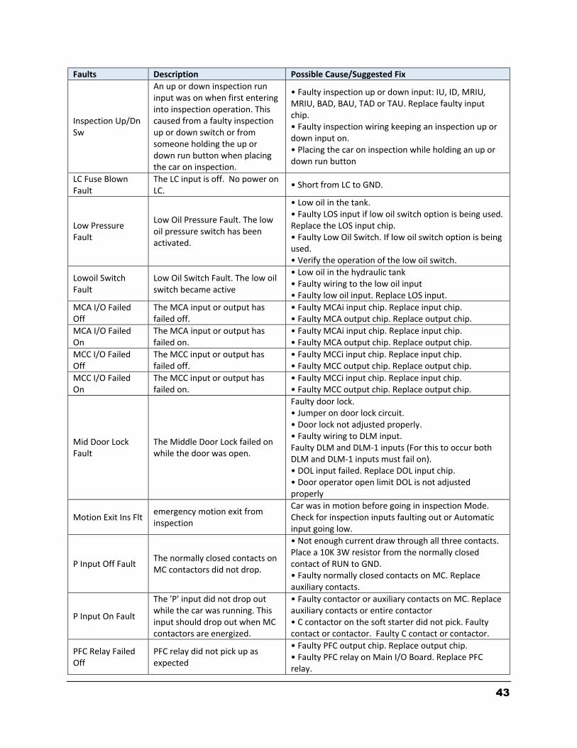
43
Faults Description Possible Cause/Suggested Fix
Inspection Up/Dn Sw
An up or down inspection run input was on when first entering into inspection operation. This caused from a faulty inspection up or down switch or from someone holding the up or down run button when placing the car on inspection.
• Faulty inspection up or down input: IU, ID, MRIU, MRIU, BAD, BAU, TAD or TAU. Replace faulty input chip. • Faulty inspection wiring keeping an inspection up or down input on. • Placing the car on inspection while holding an up or down run button
LC Fuse Blown Fault
The LC input is off. No power on LC.
• Short from LC to GND.
Low Pressure Fault
Low Oil Pressure Fault. The low oil pressure switch has been activated.
• Low oil in the tank. • Faulty LOS input if low oil switch option is being used. Replace the LOS input chip. • Faulty Low Oil Switch. If low oil switch option is being used. • Verify the operation of the low oil switch.
Lowoil Switch Fault
Low Oil Switch Fault. The low oil switch became active
• Low oil in the hydraulic tank • Faulty wiring to the low oil input • Faulty low oil input. Replace LOS input.
MCA I/O Failed Off
The MCA input or output has failed off.
• Faulty MCAi input chip. Replace input chip. • Faulty MCA output chip. Replace output chip.
MCA I/O Failed On
The MCA input or output has failed on.
• Faulty MCAi input chip. Replace input chip. • Faulty MCA output chip. Replace output chip.
MCC I/O Failed Off
The MCC input or output has failed off.
• Faulty MCCi input chip. Replace input chip. • Faulty MCC output chip. Replace output chip.
MCC I/O Failed On
The MCC input or output has failed on.
• Faulty MCCi input chip. Replace input chip. • Faulty MCC output chip. Replace output chip.
Mid Door Lock Fault
The Middle Door Lock failed on while the door was open.
Faulty door lock. • Jumper on door lock circuit. • Door lock not adjusted properly. • Faulty wiring to DLM input. Faulty DLM and DLM-1 inputs (For this to occur both DLM and DLM-1 inputs must fail on). • DOL input failed. Replace DOL input chip. • Door operator open limit DOL is not adjusted properly
Motion Exit Ins Flt emergency motion exit from inspection
Car was in motion before going in inspection Mode. Check for inspection inputs faulting out or Automatic input going low.
P Input Off Fault The normally closed contacts on MC contactors did not drop.
• Not enough current draw through all three contacts. Place a 10K 3W resistor from the normally closed contact of RUN to GND. • Faulty normally closed contacts on MC. Replace auxiliary contacts.
P Input On Fault
The 'P' input did not drop out while the car was running. This input should drop out when MC contactors are energized.
• Faulty contactor or auxiliary contacts on MC. Replace auxiliary contacts or entire contactor • C contactor on the soft starter did not pick. Faulty contact or contactor. Faulty C contact or contactor.
PFC Relay Failed Off
PFC relay did not pick up as expected
• Faulty PFC output chip. Replace output chip. • Faulty PFC relay on Main I/O Board. Replace PFC relay.
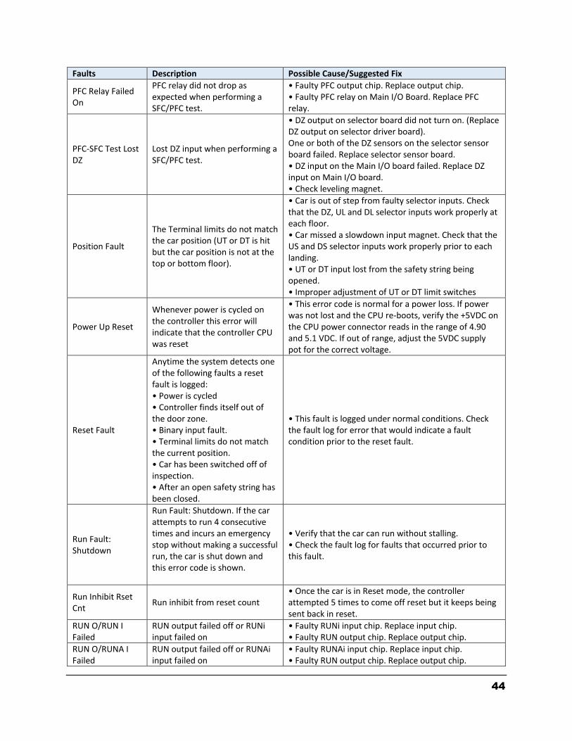
44
Faults Description Possible Cause/Suggested Fix
PFC Relay Failed On
PFC relay did not drop as expected when performing a SFC/PFC test.
• Faulty PFC output chip. Replace output chip. • Faulty PFC relay on Main I/O Board. Replace PFC relay.
PFC-SFC Test Lost DZ
Lost DZ input when performing a SFC/PFC test.
• DZ output on selector board did not turn on. (Replace DZ output on selector driver board). One or both of the DZ sensors on the selector sensor board failed. Replace selector sensor board. • DZ input on the Main I/O board failed. Replace DZ input on Main I/O board. • Check leveling magnet.
Position Fault
The Terminal limits do not match the car position (UT or DT is hit but the car position is not at the top or bottom floor).
• Car is out of step from faulty selector inputs. Check that the DZ, UL and DL selector inputs work properly at each floor. • Car missed a slowdown input magnet. Check that the US and DS selector inputs work properly prior to each landing. • UT or DT input lost from the safety string being opened. • Improper adjustment of UT or DT limit switches
Power Up Reset
Whenever power is cycled on the controller this error will indicate that the controller CPU was reset
• This error code is normal for a power loss. If power was not lost and the CPU re-boots, verify the +5VDC on the CPU power connector reads in the range of 4.90 and 5.1 VDC. If out of range, adjust the 5VDC supply pot for the correct voltage.
Reset Fault
Anytime the system detects one of the following faults a reset fault is logged: • Power is cycled • Controller finds itself out of the door zone. • Binary input fault. • Terminal limits do not match the current position. • Car has been switched off of inspection. • After an open safety string has been closed.
• This fault is logged under normal conditions. Check the fault log for error that would indicate a fault condition prior to the reset fault.
Run Fault: Shutdown
Run Fault: Shutdown. If the car attempts to run 4 consecutive times and incurs an emergency stop without making a successful run, the car is shut down and this error code is shown.
• Verify that the car can run without stalling. • Check the fault log for faults that occurred prior to this fault.
Run Inhibit Rset Cnt
Run inhibit from reset count • Once the car is in Reset mode, the controller attempted 5 times to come off reset but it keeps being sent back in reset.
RUN O/RUN I Failed
RUN output failed off or RUNi input failed on
• Faulty RUNi input chip. Replace input chip. • Faulty RUN output chip. Replace output chip.
RUN O/RUNA I Failed
RUN output failed off or RUNAi input failed on
• Faulty RUNAi input chip. Replace input chip. • Faulty RUN output chip. Replace output chip.

45
Faults Description Possible Cause/Suggested Fix
RUNA I/O Failed Off
The RUNA input or output has failed off.
• Faulty wiring at the SC terminal. Verify that the valve common SC terminal on the Main I/O board is connected properly. • Faulty RUNAi input. Replace RUNAi input chip. • Faulty RUNA output. Replace RUNA output chip. • Faulty RUN output. Replace RUN output chip.
RUNA I/O Failed On
The RUNA input or output has failed on
• Faulty wiring at the SC terminal. Verify that the valve common SC terminal on the Main I/O board is connected properly. • Faulty RUN output. Replace RUN output chip. • Faulty RUNAi input. Replace RUNAi input chip. • Faulty RUNA output. Replace RUNA output chip.
RUNA O/RUN I Failed
RUNA output or RUNI input failed
• RUNA output failed off. Replace the RUNA output chip. • RUNI input failed off. Replace the RUNI input chip.
Safety String Fault Safety string fault occurs from the safety string being open (SS input is off).
• The safety string is open (SS input if off). Refer to the job prints and check all circuits ahead of the SS input.
SFC Relay Failed Off
SFC relay did not pick up as expected.
• Faulty SFC output chip. Replace output chip. • Faulty SFC relay on Main I/O Board. Replace SFC relay.
SFC Relay Failed On
SFC relay did not drop as expected when performing a SFC/PFC test.
• Faulty SFC output chip. Replace output chip. • Faulty SFC relay on Main I/O Board. Replace SFC relay.
Stalled Fault
Stall Fault occurs if the motion run timer exceeds the stall protection time. The motion run timer is incremented while the car is trying to run.
• Increase Stall Timer on the controller under Adjustable Variables and Car Timers. Set the timer to allow the car to run the entire hoistway at the recovery speed. • Faulty or improperly adjusted valve. • Faulty pump motor.
Stop Switch Fault Stop switch is pulled while the car is in motion.
• Stop switch is pulled. • Faulty wire connection in the stop switch circuit.
Top Door Lock Fault
The Top Door Lock failed on while the door was open.
• Faulty door lock. • Jumper on door lock circuit. • Door lock not adjusted properly. • Faulty wiring to DLT input. • Faulty DLT and DLT-1 inputs (For this to occur both DLT and DLT-1 inputs must fail on). • DOL input failed. Replace DOL input chip. • Door operator open limit DOL is not adjusted properly
UPF I/O Failed On The UF (SUF) input or output has failed on.
• Faulty UFi (SUFi) input (replace input chip). • Faulty UF (SUF) output (replace output chip).
UL and DL Off Fault
Both UL and DL level sensors are off when car is at a floor.
• Faulty adjustment of the selector head. • Worn selector guides. Replace selector guides. • Faulty Door Zone Magnet. If this fault occurs at one particular floor, replace the door zone magnet at the floor. • Faulty sensor board. Replace the selector sensor board.

46
Faults Description Possible Cause/Suggested Fix
UL Failed On Fault UL Failed On Fault. The UL leveling sensor did not go off during a run.
• UL hall effect sensor bad on selector sensor board. Replace sensor board. • UL Output Driver failed on. Replace output on selector driver board. • UL traveling cable wire is shorted to 120 VAC. Remove input wire to Main I/O board and verify that LED goes out. Correct short condition. • UL inputs failed on. Replace the selector driver board.
UL,DL & DZ Off at FL
UL, DL & DZ sensors off at floor. The car thinks it should be at a floor or is at a floor and all the floor sensors have turned off.
• Loss of power on the selector. • Faulty cable from the selector driver board to the sensor or sensor board. • Faulty wiring from the selector driver board to the Main I/O board.
Up Directional Fault
Car unexpectedly hit the Up Normal Limit while running up.
• Faulty wiring for the UN limit. • The power common to the limit switches (CS) was lost. Check safety string prior to the CS terminal.
UP I/O Failed Off The UP (SU) input or output has failed off
• Fault on Safety Processor. The Safety Processor is located on the MAIN I/O board. This device can disable the run control to the DNR output chip. Check if the SAF-PROC or SAF-PAL FAULT LEDs turn on when the car attempts to run. Check the elevator service, faults, and inputs/outputs on the Safety Processor status of the LCD Interface. • Faulty wiring to the SC common on the MAIN I/O board. • Faulty wiring to the SU terminal on the MAIN I/O board. • Faulty wiring to the Up valve • Faulty UP (SU) output or UPi (SUi) input. Replace the UP (SU) output and UPi (SUi) input chip. • RUN outputs or MC auxiliary contact not making properly. Verify the operation and contact integrity.
UP I/O Failed On The UP (SU) input or output has failed on.
• Faulty UP (SU) output. Replace the UP (SU) output chip. • Faulty UPi (SUi) input. Replace UPi (SUi) input chip.
UPF I/O Failed Off The UPF (SUF) input or output has failed off.
• Fault on Safety Processor Board. The Safety Processor Board can disable the run control to the UPF output chip. Check if the PIC or PAL inhibit LED turns on when the car attempts to run. Check the elevator service, faults, and inputs/outputs on the Safety Processor Board LCD. • Faulty wiring to the SC common on the MAIN I/O board. • Faulty wiring to the SUF terminal on the MAIN I/O board. • Faulty wiring to the Up Fast valve • Faulty SDFi input (replace input chip). • Faulty SDF output (replace output chip).
UPF I/O Failed On The UPF (SUF) input or output has failed on.
• Faulty UFi (SUFi) input (replace input chip). • Faulty UF (SUF) output (replace output chip).
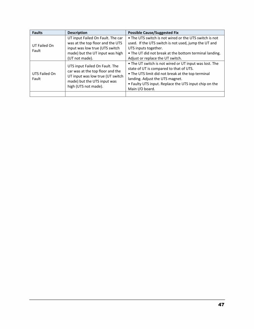
47
Faults Description Possible Cause/Suggested Fix
UT Failed On Fault
UT input Failed On Fault. The car was at the top floor and the UTS input was low true (UTS switch made) but the UT input was high (UT not made).
• The UTS switch is not wired or the UTS switch is not used. If the UTS switch is not used, jump the UT and UTS inputs together. • The UT did not break at the bottom terminal landing. Adjust or replace the UT switch.
UTS Failed On Fault
UTS input Failed On Fault. The car was at the top floor and the UT input was low true (UT switch made) but the UTS input was high (UTS not made).
• The UT switch is not wired or UT input was lost. The state of UT is compared to that of UTS. • The UTS limit did not break at the top terminal landing. Adjust the UTS magnet. • Faulty UTS input. Replace the UTS input chip on the Main I/O board.

48
4.6.1 DETAILED FAULT DATA SRV Service Flag 0 = Out of Service 1 = Automatic 2 = Independent 3 = Load Weighing Bypass 4 = Attendant 5 = Code Blue 6 = Fire Phase 2 7 = Emergency Power 8 = Earthquake Emergency 9 = Fire Phase 1 Main Egress 10 = Fire Phase 1 Alternate Egress 11 = Homing 12 = Reset Run Up 13 = Reset Run Down 14 = Low Oil Operation 15 = Return to Lobby 16 = Load Overload 17 = Massachusetts Medical Emergency 18 = Calibrate load weigher 19 = CS Elevator Off 20 = HS Elevator Off 21 = Low Pressure Operation 22 = Hospital Service Operation 23 = VIP Service Operation 24 = Security Recall 25 = Sabbath service 26 = TUG Service operation PRC Process Flag 1 = Reset 2 = Inspection 3 = Motion:
hsf=1, dir=1, Up Fast
hsf=0, dir=1, ul=0 Up Transition
hsf=0, dir=1, ul=1, Up Leveling
hsf=1, dir=2, Down Fast
hsf=0, dir=2, dl=0, Down Transition
hsf=0, dir=2, dl=1, Down Leveling 4 = Motion Mode 1 – Soft Start 5 = Motion Mode 2 – Constant Acceleration 6 = Motion Mode 3 – Roll Over to Max Velocity 7 = Motion Mode 4 – Constant Velocity 8 = Motion Mode 5 – Roll Over to Deceleration 9 = Motion Mode 6 – Constant Deceleration
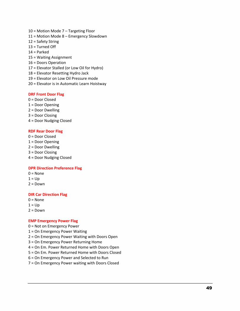
49
10 = Motion Mode 7 – Targeting Floor 11 = Motion Mode 8 – Emergency Slowdown 12 = Safety String 13 = Turned Off 14 = Parked 15 = Waiting Assignment 16 = Doors Operation 17 = Elevator Stalled (or Low Oil for Hydro) 18 = Elevator Resetting Hydro Jack 19 = Elevator on Low Oil Pressure mode 20 = Elevator is in Automatic Learn Hoistway DRF Front Door Flag 0 = Door Closed 1 = Door Opening 2 = Door Dwelling 3 = Door Closing 4 = Door Nudging Closed RDF Rear Door Flag 0 = Door Closed 1 = Door Opening 2 = Door Dwelling 3 = Door Closing 4 = Door Nudging Closed DPR Direction Preference Flag 0 = None 1 = Up 2 = Down DIR Car Direction Flag 0 = None 1 = Up 2 = Down EMP Emergency Power Flag 0 = Not on Emergency Power 1 = On Emergency Power Waiting 2 = On Emergency Power Waiting with Doors Open 3 = On Emergency Power Returning Home 4 = On Em. Power Returned Home with Doors Open 5 = On Em. Power Returned Home with Doors Closed 6 = On Emergency Power and Selected to Run 7 = On Emergency Power waiting with Doors Closed

50
MED Medical Emergency 0 = No Medical Emergency Service 1 = Recall Car to Medical Emergency Recall Floor 2 = At Return Floor with Door Open (Return Complete) 4 = On EMS Car Call Service 5 = On EMS Car Hold Service (key off but not at the recall floor) CBL Code Blue Flag 0 = No Code Blue 1 = Recall to Emergency Floor 2 = At Code Blue Floor 3 = At Code Blue Floor with Door Open 4 = Finished Code Blue EQU Earthquake Flag 0 = Not on Earthquake Operation 1 = Earthquake Sensor Activated 2 = Counterweight Derailment Sensor Activated 3 = Recover Away From the Counterweight 4 = Stopped at a Floor FIR Fire Flag 0 = Not on Fire Service 1 = Phase 1 Main Egress Return 2 = Phase 1 Alternate Egress Return 3 = Phase 1 Completed 4 = Phase 2 Door Hold 5 = Phase 2 Constant Pressure Door Open 6 = Phase 2 Constant Pressure Door Close 7 = Phase 2 Door Hold RFI Rear Fire Flag 0 = Not on Fire Service 1 = Phase 1 Main Rear Egress Return 2 = Phase 1 Alternate Rear Egress Return 3 = Phase 1 Completed 4 = Phase 2 Rear Door Hold 5 = Phase 2 Constant Pressure Rear Door Open 6 = Phase 2 Constant Pressure Rear Door Close 7 = Phase 2 Rear Door Hold HSF High Speed Flag 0 = No High Speed 1 = High Speed STF Start Flag 0 = Not valid Start 1 = Start of Run

51
CAL Direction of Calls 0 = No Call 1 = Above Call 2 = Below Call 3 = Above and Below Calls ESP Emergency Stop Flag 1 = Emergency Stop NST Need to Stop Flag 1 = Car need to stop at next floor RLV Re‐level Flag 1 = Car in re‐leveling STE Step Flag 1 = Step to the next position (non‐distance feedback) PDO Pre‐open Door Flag 1 = Pre‐open door STO Next Stop Floor Floor number of next stop INS Inspection Status Flag. (Status bit set to “1” when switch is on) Bit 0: Car Top Inspection Bit 1: Machine Room Inspection Bit 2: Access Bit 3: In Car Inspection Bit 4: Lock Bypass Bit 5: Gate Bypass Bit 6: Not in Automatic (AUTO==0) NDS Next Car Up Sequence 0 = Initiate Next Up Door Open 1 = Opening Next Up Door 2 = Door full open on Next Up 3 = Allow door close for onward call 4 = Allow door close while on next up DEV – Boards not communicating. See page 53. TXE - Transmitter Buffer (1 = Transmit Buffer Empty) CS1 - Communication 1 Source # = Interrupt status for com port # 1 CS2 - Communication 2 Source # = Com port # 1 status CS3 - Communication 3 Source 0 = Group transmit buffer empty 1 = Group transmit buffer not empty
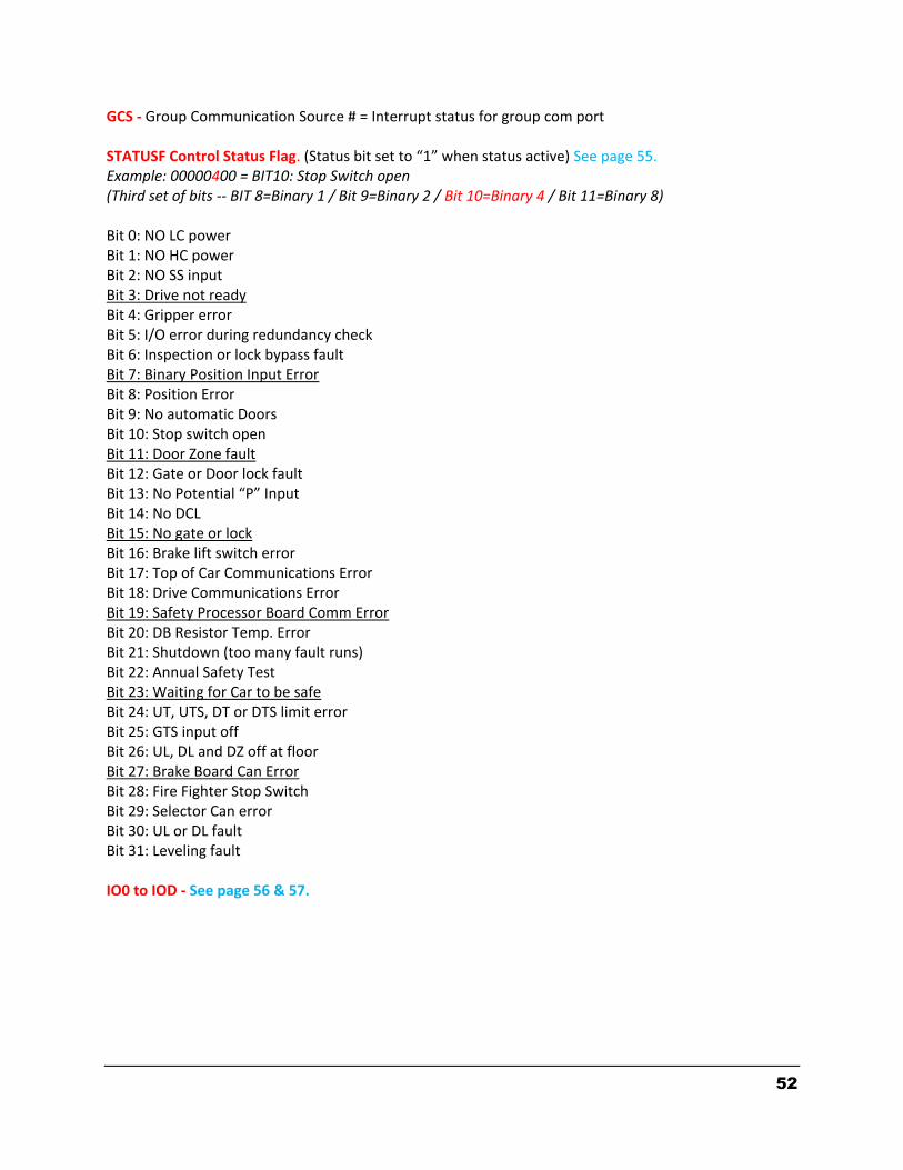
52
GCS - Group Communication Source # = Interrupt status for group com port STATUSF Control Status Flag. (Status bit set to “1” when status active) See page 55. Example: 00000400 = BIT10: Stop Switch open (Third set of bits -- BIT 8=Binary 1 / Bit 9=Binary 2 / Bit 10=Binary 4 / Bit 11=Binary 8) Bit 0: NO LC power Bit 1: NO HC power Bit 2: NO SS input Bit 3: Drive not ready Bit 4: Gripper error Bit 5: I/O error during redundancy check Bit 6: Inspection or lock bypass fault Bit 7: Binary Position Input Error Bit 8: Position Error Bit 9: No automatic Doors Bit 10: Stop switch open Bit 11: Door Zone fault Bit 12: Gate or Door lock fault Bit 13: No Potential “P” Input Bit 14: No DCL Bit 15: No gate or lock Bit 16: Brake lift switch error Bit 17: Top of Car Communications Error Bit 18: Drive Communications Error Bit 19: Safety Processor Board Comm Error Bit 20: DB Resistor Temp. Error Bit 21: Shutdown (too many fault runs) Bit 22: Annual Safety Test Bit 23: Waiting for Car to be safe Bit 24: UT, UTS, DT or DTS limit error Bit 25: GTS input off Bit 26: UL, DL and DZ off at floor Bit 27: Brake Board Can Error Bit 28: Fire Fighter Stop Switch Bit 29: Selector Can error Bit 30: UL or DL fault Bit 31: Leveling fault IO0 to IOD - See page 56 & 57.
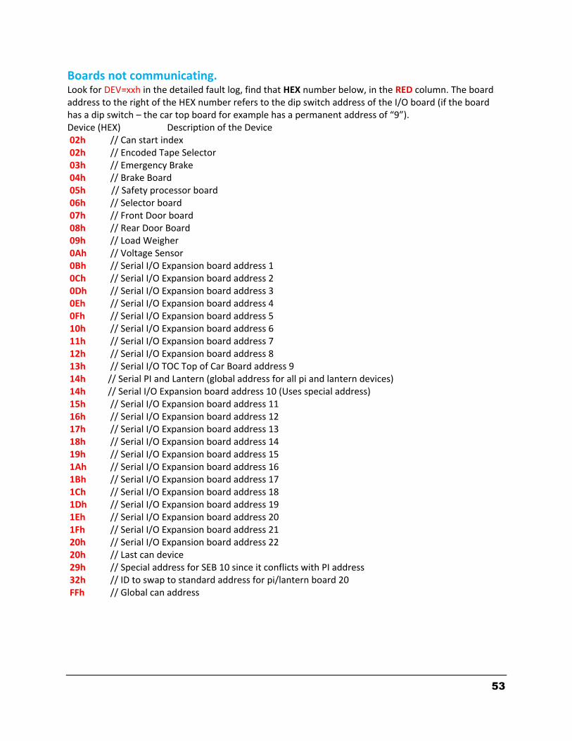
53
Boards not communicating. Look for DEV=xxh in the detailed fault log, find that HEX number below, in the RED column. The board address to the right of the HEX number refers to the dip switch address of the I/O board (if the board has a dip switch – the car top board for example has a permanent address of “9”). Device (HEX) Description of the Device 02h // Can start index 02h // Encoded Tape Selector 03h // Emergency Brake 04h // Brake Board 05h // Safety processor board 06h // Selector board 07h // Front Door board 08h // Rear Door Board 09h // Load Weigher 0Ah // Voltage Sensor 0Bh // Serial I/O Expansion board address 1 0Ch // Serial I/O Expansion board address 2 0Dh // Serial I/O Expansion board address 3 0Eh // Serial I/O Expansion board address 4 0Fh // Serial I/O Expansion board address 5 10h // Serial I/O Expansion board address 6 11h // Serial I/O Expansion board address 7 12h // Serial I/O Expansion board address 8 13h // Serial I/O TOC Top of Car Board address 9 14h // Serial PI and Lantern (global address for all pi and lantern devices) 14h // Serial I/O Expansion board address 10 (Uses special address) 15h // Serial I/O Expansion board address 11 16h // Serial I/O Expansion board address 12 17h // Serial I/O Expansion board address 13 18h // Serial I/O Expansion board address 14 19h // Serial I/O Expansion board address 15 1Ah // Serial I/O Expansion board address 16 1Bh // Serial I/O Expansion board address 17 1Ch // Serial I/O Expansion board address 18 1Dh // Serial I/O Expansion board address 19 1Eh // Serial I/O Expansion board address 20 1Fh // Serial I/O Expansion board address 21 20h // Serial I/O Expansion board address 22 20h // Last can device 29h // Special address for SEB 10 since it conflicts with PI address 32h // ID to swap to standard address for pi/lantern board 20 FFh // Global can address

54
STATUSF Control Status Flag
8th Digit → 0000 0000 ← 1st Digit
Gate or Door Lock Flt
1
No Potential "P" Input
0
No DCL
1
No Gate or Lock
1
4th Digit
Decoding IO0 - IOD
IO1 = 2C h
0 1 2 3 4 5 6 70000 0001 0010 0011 0100 0101 0110 0111
8 9 A B C D E F1000 1001 1010 1011 1100 1101 1110 1111
0 0 1 0 1 1 0 0
RLM DLT DLM DLB UT3 UT2 UT1 UTS
IO1
In the example below we are illustrating IO1=2Ch. The h signifies that the number is in hexadecimal notation, the actual hexadecimal number is 2C and the h can be ignored.
The 2C is converted to binary using the chart above (green) and the binary values transferred to the appropriate IO line, IO1 in our example (blue). In binary notation we count from the right - LSB – (Least Significant Bit) to the left – MSB - (Most significant Bit), which is why binary 1 is written as 0001 – it begins at the right.
A binary 1 indicates a high input or output, meaning it is ON . A binary 0 indicates the input or output is low, meaning it is OFF .
In our example above we can see that UTS, UT1, DLB, DLT and RLM are all low, or OFF, and UT2, UT3, and DLM are all ON.
Decoding Statusf
Statusf = 0000 D000
0 1 2 3 4 5 6 70000 0001 0010 0011 0100 0101 0110 0111
8 9 A B C D E F1000 1001 1010 1011 1100 1101 1110 1111
1st Digit
4th Digit
Starting from the right it can be seen that there is a Gate or Door Lock Fault , a No DCL fault, and a No Gate or Lock fault. Safety Processor Status and Inspection Status work similarly.
8th Digit
Example: Statusf=0000 D000 = 0000 0000 0000 0000 1101 0000 0000 0000
Satusf is 32 bits long and each digit in =0000 0000 is four bits.

55
0 1 2 3 4 5 6 7
0000 0001 0010 0011 0100 0101 0110 0111
8 9 A B C D E F
1000 1001 1010 1011 1100 1101 1110 1111
Leveling Fault UL or DL Fault Selector Can Err Fire Fighter Stop Sw
Brake Board CAN Err UL, DL, DZ Off At Floor GTS Input Off UT, UTS, DT, DTS Lim Err
8th Digit =
7th Digit =
Waiting For Safe Annual Safety Test Too Many Flt Runs DB Resistor Temp Err
Safety Proc Comm Err Drive Comm Error TOC Comm Error Brake Lift Sw Err
6th Digit =
5th Digit =
No Gate or Lock No DCL No Potential "P" Input Gate or Door Lock Flt
Door Zone Fault Stop Sw Open No Automatic Doors Position Error
4th Digit =
3rd Digit =
Binary Position Err Ins or Lock Bypass Error IO Error - Redundancy Gripper Error
Drive Not Ready NO SS Input NO HC Power NO LC Power
2nd Digit =
STATUSF Control Status Flag
8th Digit → 0000 0000 ← 1st Digit
1st Digit =
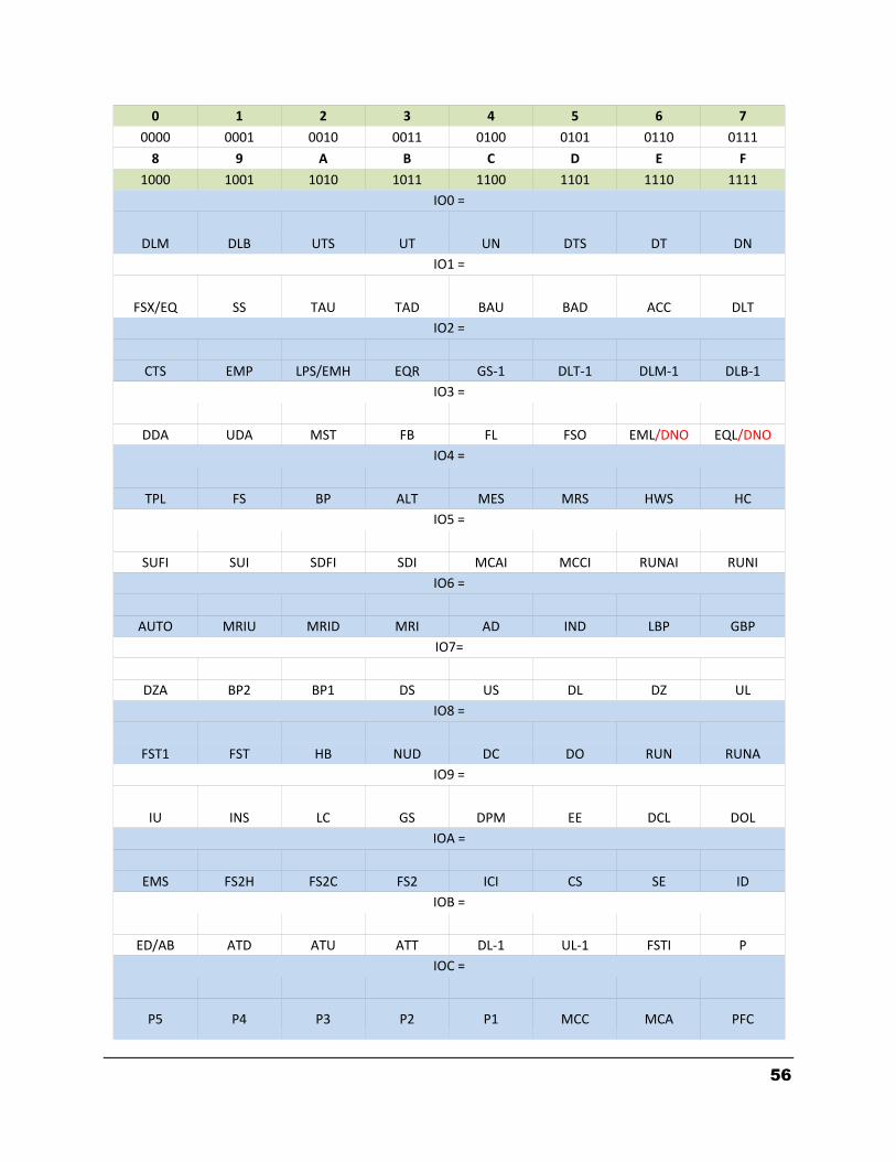
56
0 1 2 3 4 5 6 7
0000 0001 0010 0011 0100 0101 0110 0111
8 9 A B C D E F
1000 1001 1010 1011 1100 1101 1110 1111
IO0 =
DLM DLB UTS UT UN DTS DT DN
IO1 =
FSX/EQ SS TAU TAD BAU BAD ACC DLT
IO2 =
CTS EMP LPS/EMH EQR GS‐1 DLT‐1 DLM‐1 DLB‐1
IO3 =
DDA UDA MST FB FL FSO EML/DNO EQL/DNO
IO4 =
TPL FS BP ALT MES MRS HWS HC
IO5 =
SUFI SUI SDFI SDI MCAI MCCI RUNAI RUNI
IO6 =
AUTO MRIU MRID MRI AD IND LBP GBP
IO7=
DZA BP2 BP1 DS US DL DZ UL
IO8 =
FST1 FST HB NUD DC DO RUN RUNA
IO9 =
IU INS LC GS DPM EE DCL DOL
IOA =
EMS FS2H FS2C FS2 ICI CS SE ID
IOB =
ED/AB ATD ATU ATT DL‐1 UL‐1 FSTI P
IOC =
P5 P4 P3 P2 P1 MCC MCA PFC
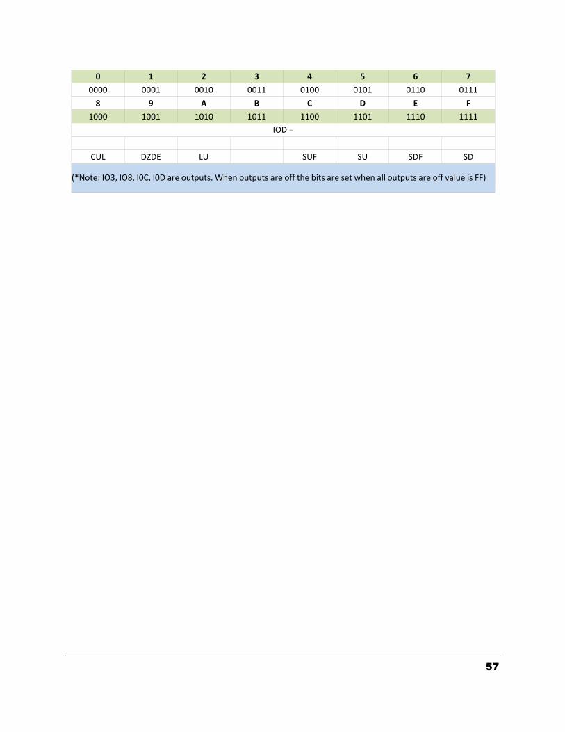
57
0 1 2 3 4 5 6 7
0000 0001 0010 0011 0100 0101 0110 0111
8 9 A B C D E F
1000 1001 1010 1011 1100 1101 1110 1111
IOD =
CUL DZDE LU SUF SU SDF SD
(*Note: IO3, IO8, I0C, I0D are outputs. When outputs are off the bits are set when all outputs are off value is FF)

58
4.6.2 SAFETY PROCESSOR FAULTS
DESCRIPTION AND CAUSE No Flt No fault is recorded in this index location.
Invalid Invalid fault number. (This can only be caused by a programming error in the chip).
EEprom EEprom fault. Defective EEprom device or EEprom device is not installed. The car will not be able to run until the EEprom is installed or replaced.
UTS Sp UTS Speed Fault. The car hit the UTS limit at a higher velocity than the value set for the UTS Velocity adjustable variable. The car will immediately shut down.
DTS Sp DTS Speed Fault. The car hit the DTS limit at a higher velocity than the value set for the DTS Velocity adjustable variable. The car will immediately shut down.
UT Spd UT Speed Fault. The car hit the UT limit at a higher velocity than the value set for the UT Velocity adjustable variable. The car will immediately shut down.
DT Spd DT Speed Fault. The car hit the DT limit at a higher velocity than the value set for the DT Velocity adjustable variable. The car will immediately shut down.
INS Sp Inspection Speed Fault. The car exceeded the INS Velocity adjustable variable while running on inspection. The car will immediately shut down.
LEV Sp Leveling Speed Fault. The car exceeded the LEV Velocity adjustable variable while leveling with a door open. The car will immediately shut down.
DL/GS Door Lock/Gate Switch Fault. Car is moving outside the door zone with the door open. The car will immediately shut down.
IO Flt I/O Fault. An input is on in error. The Elev Serv display will show the I/O error. Possible causes are as follows: 1. All inspection inputs and the auto input are off. 2. More than one inspection or auto input is on at the same time. 3. A bypass input is on while the car is not on Car top inspection. 4. Both up and down run output from the main CPU are on at the same time. The car will not be able to run until the error is cleared.
INS DO Inspection Door Open Fault. A door is open while running on inspection and the gate and locks are not being bypassed. The car will immediately shut down.
Pls Er Pulse Error. Not enough pulses have occurred during the Pulse Fault Time period. This error is detected only on automatic operation. Verify that the pulse LED on the Safety Processor board blinks while the car is running on inspection. Possible causes are as follows: 1. Improper connection for PP and PPS. Refer to the job specific prints. 2. PP and PPS field wires need to be swapped. 3. Photocoupler in selector is faulty. Call the Factory. 4. Voltage from PP to 0V on the Safety Processor Board is less than 10 VDC with the PP and PPS wires disconnected. Call the Factory.

59
Section 5 - LCD INTERFACE 5.1 OPERATING THE LCD INTERFACE
The LCD interface board uses a 2 line by 24 character display and four buttons. This interface allows the user to adjust parameters, view critical controller information, to implement the controller setup and to view the elevator status. Upon power-up the display shows a blinking GALaxy name to indicate the controller is running as show below:
UP button is used to scroll up to the next menu item or to increment a data value.
DOWN button is used to scroll down to the next menu item or to decrement a data value.
MODE button is used to go back to the previous menu or to select a digit of a data value.
ENTER button is used to select the menu item or to complete the operation of changing a data value.
The potentiometer is used to adjust the viewing angle. It will make the display lighter or darker.
The four inputs buttons used with the LCD are, UP, DOWN, MODE and ENTER. The UP and DOWN buttons are used to scroll up and down to each menu item. When an appropriate menu item is reached, the ENTER button is used to select the item. Some menu items, once selected, show a second menu. Again, use the UP and DOWN buttons to scroll through the menu items and the ENTER button to select a particular item. The MODE button is used to go back to the previous menu. When a menu item is an adjustable variable, select the item with the ENTER button and change the variable with the UP or DOWN button. The MODE button is used to move the cursor to the next digit. When the appropriate value is reached, used the ENTER button to complete the variable change operation and return to the current menu.

60
5.2 THE LCD MENU STRUCTURE
GALaxyCONTROLLER
GALaxyElevator Status
GALaxySet Calls and lockouts
GALaxyInputs and outputs
GALaxyJob Statistics
GALaxyAdjustable Variables
GALaxyDate and Time
GALaxyFault Log
GALaxySelect Video Display
GALaxySoftware Version
GALaxyDiagnostics
LCD Interface Main
MenuPower
Up
Mode

61
5.3 SET DATE AND TIME It is important to set the date and time on the controller clock so that the fault log shows the correct time sequence that faults occur.
Set Date and Time
GALaxyDate and Time
Date and TimeSet Date and Time
Date and TimeView Day of the Week
Day of the WeekSaturday
Press Enter to Set14:45 3/28/2014
Press Enter to Set14:45 3/28/2014
Press Enter to Set14:46 3/28/2014
Press Enter to Set14:45 3/28/2014
Enter
Enter
Enter
Mode
Down
Mode
Mode
Mode
Up
Down
Selects the next field.
Increments Number
Decrements Number
Enter Stores the Value
Enter Stores the Value
Enter Stores the Value
Enter Stores the Value

62
LCD Interface Main Menu
Adjustable Variables
GALaxyAdjustable Variables
Adjustable VariablesCar Motion
Adjustable VariablesCar Timers
Adjustable VariablesCar Options
Car TimersY Delta Time = 0001.5
Car TimersFault Time = 0002.0
Adjustable VariablesGroup Dispatch
Adjustable VariablesGroup Options
Mode
Enter
Car TimersReset Time = 0005.0
Car TimersGen / Fan Time = 0360.0
Min=0 Max=10.0 SecFault Time = 0002.0
Fault Time = 0002.0
Mode Select Next Field
Fault Time = 0002.0
Down Decrement Digit
Fault Time = 0001.0
Fault Time = 0002.0
Up Increment Digit
5.3 ADJUSTABLE VARIABLES
All field variables are adjustable from the LCD interface. Values can be changed within the valid minimum and maximum range. A complete list of field adjustable variables and the minimum and maximum values for each is shown below:

63
5.4 Field Adjustable Variables
Table 1: Car Motion
Field
Variable Min Max Initial Units Description
Inspect
Speed
0
150
40
fpm
Inspection Speed.
Maximum car speed while running on inspection.
Preopen
Delay
0
3200
0.5
sec
Preopen Delay.
Delay time to preopen the door starting from when the car reaches 3
inches from dead level and the door can safely be opened.
Relev Dly
Tim
0
2
1
sec
Relevel Delay Time.
The amount of delay time before the car will re‐level. This would be used
for jobs that have excessive rope stretch.
Short Fl
Cntrl
0
7
0
‐
Short Floor Control.
0 = Default is that the car relevels to the short floor.
+1 = Car will make a run between very short floors instead of re‐ leveling.
+2 = Short floor slowdown magnets between short floors (non‐distance
feedback).
+4 = Mid Short floor slowdown magnets between short floors (non‐
distance feedback).
Short Fl hsf
0
1
0
‐
Short Floor hsf (High Speed Flag) With No high Speed Valve.
Controller makes a run but only with one valve. 0 = HS Output,
1 = No HS Out
Shrt Fl Dn
SD
0
30
0
sec
Short Floor Down Slowdown.
Hydro ‐ There are no slow down magnets between short floors. This is a
timer to run down high speed in seconds. If the timer is set to zero,
controller will immediately level looking for the other zone.
This should only be used if second selector is utilized.

64
Shrt Fl Up
SD
0
30
0
sec
Short Floor Up Slowdown.
Hydro ‐ There are no slow down magnets between short floors. This is
timer to run up high speed in seconds. If the timer is set to zero,
controller will immediately level looking for the other zone.
This should only be used if second selector is utilized.

65
Table 1: Car Motion
Field
Variable Min Max Initial Units Description
Soft Stop
Time
0.2
30
1
sec
Soft Stop Time.
For Hydraulic Elevators – time the motor is kept running after the valve
is turned off.
For Traction Elevators – time that zero speed is held until the brake is
set.
Inspect
Speed ISER
0
150
40
fpm
Inspection Speed.
When this value is set greater than or equal to the contract speed the
ISER output will turn on to allow the car to run higher than leveling
speed on inspection. Appropriate valve setup is required for this function
to work.

66
Table 2: Car Timers
Field
Variable Min Max Initial Units Description
Att Buz
Delay
0
900
60
sec
Attendant Buzzer Delay.
Buzzer sounds if a hall call is entered and the car has not started
moving within this delay time. This function is disabled when set to
zero.
Car Call
Dwell
1
60
2
sec
Car Call Dwell.
Door open dwell time when answering a car call only.
CB Door
Time
1
3200
60
sec
Code Blue Door Time.
Door time for Code blue operation once elevator is at the emergency
floor before EMS is energized.
Door Delay
Time
0
1.5
0
sec
Door Delay Time.
Delay time between DO and DC to switch when opening or closing the
door.
Door Fail
Time
10
3200
25
sec
Door Fail Time.
Time with power on the door without getting the door open limit.
Fault Time
0
10
2
sec
Fault Time.
Delay time before allowing the car to run after a fault occurs.
Gen/Lt/Fan
Time
30
3200
360
sec
Generator Run/Cab Light/Fan Time.
Length of time to leave the generator running or the Cab light and fan
on after there is no longer a demand to run.
Hall Call
Dwell
1
60
4
sec
Hall Call Dwell.
Door open dwell time when answering a hall call or both a hall and car
call.
Handicap
Dwell
1
120
25
sec
Handicap Dwell.
Extended door time from pressing the ED button in the car.
Lant Off
Time
0
2
0.2
sec
Lantern Off Time.
Used for double stroke gongs. The lantern off time is the delay time
after the lantern first turns on until it turns off.

67
Table 2: Car Timers
Field
Variable Min Max Initial Units Description
Lant On
Time
0
2
0.7
sec
Lantern On time.
Used for double stroke gongs. The lantern will turn on, turn off and
then turn on again. The Lantern on time is the delay time from when
the lantern first turns on until it turns on the second time.
Lobby Dwell
1
60
5
sec
Lobby Dwell.
Door open dwell time for a car at the lobby.
ManDoor
Buz Dly
0
900
0
sec
Manual Door Buzzer Delay.
On a car with manual doors, sound the buzzer if the door is left open
and a call is entered after this time delay. This function is disabled
when set to zero.
Non
Interfer T
1
60
2
sec
Non‐Interference Time.
Time between when you stop and when you can run again.
Nudging
Time
20
3200
60
sec
Nudging Time.
Delay time for a door to be held before going into nudging.
Pas Chime
Time
0.2
2
0.5
sec
Floor Passing Chime Time.
Length of time the floor passing chime will sound when a floor is
passed.
Reset Time
0
10
5
sec
Reset Time.
Delay time in the reset mode before allowing the car to run.
Run Cycle
Time
0
300
0
hours
Run Cycle Time.
Used to initiate a run when the elevator has been sitting idle for a
period of time. Used for jobs that have high friction bearing machines.
Short Dwell
Tim
0
60
1
sec
Short Door Dwell Time.
Door open dwell time when the doors re‐open on a door open button,
electric eye, safety edge or door hold button.
Stall Time
20
3200
60
sec
Stall Time.
Maximum time a run is requested but the car is not moving.

68
Table 2: Car Timers
Field
Variable Min Max Initial Units Description
Video Time
out
0
3200
0
sec
Video Time‐out.
Turn off the machine room video after this timer times out. This
function is disabled when set to zero.
Y Delta
Time
1
5
1.5
sec
Y‐Delta Time.
Transfer time to change motor from Y start to Delta run. Timer also
used for DEL or MCX turn on time with controllers without y‐delta
starters.
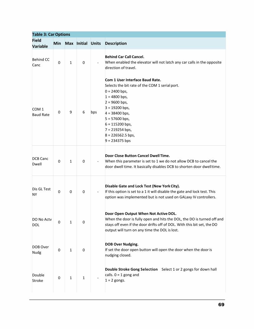
69
Table 3: Car Options
Field
Variable Min Max Initial Units Description
Behind CC
Canc
0
1
0
‐
Behind Car Call Cancel.
When enabled the elevator will not latch any car calls in the opposite
direction of travel.
COM 1
Baud Rate
0
9
6
bps
Com 1 User Interface Baud Rate.
Selects the bit rate of the COM 1 serial port.
0 = 2400 bps,
1 = 4800 bps,
2 = 9600 bps,
3 = 19200 bps,
4 = 38400 bps,
5 = 57600 bps,
6 = 115200 bps,
7 = 219254 bps,
8 = 226562.5 bps,
9 = 234375 bps
DCB Canc
Dwell
0
1
0
‐
Door Close Button Cancel Dwell Time.
When this parameter is set to 1 we do not allow DCB to cancel the
door dwell time. It basically disables DCB to shorten door dwell time.
Dis GL Test
NY
0
0
0
‐
Disable Gate and Lock Test (New York City).
If this option is set to a 1 it will disable the gate and lock test. This
option was implemented but is not used on GALaxy IV controllers.
DO No Actv
DOL
0
1
0
Door Open Output When Not Active DOL.
When the door is fully open and hits the DOL, the DO is turned off and
stays off even if the door drifts off of DOL. With this bit set, the DO
output will turn on any time the DOL is lost.
DOB Over
Nudg
0
1
0
DOB Over Nudging.
If set the door open button will open the door when the door is
nudging closed.
Double
Stroke
0
1
1
‐
Double Stroke Gong Selection Select 1 or 2 gongs for down hall
calls. 0 = 1 gong and
1 = 2 gongs.
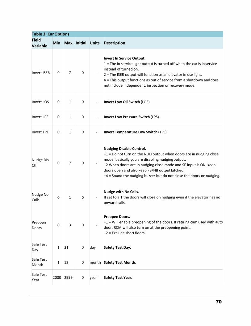
70
Table 3: Car Options
Field
Variable Min Max Initial Units Description
Invert ISER
0
7
0
‐
Invert In Service Output.
1 = The in service light output is turned off when the car is in service
instead of turned on.
2 = The ISER output will function as an elevator in use light.
4 = This output functions as out of service from a shutdown and does
not include independent, inspection or recovery mode.
Invert LOS
0
1
0
‐
Invert Low Oil Switch (LOS)
Invert LPS
0
1
0
‐
Invert Low Pressure Switch (LPS)
Invert TPL
0
1
0
‐
Invert Temperature Low Switch (TPL)
Nudge Dis
Ctl
0
7
0
‐
Nudging Disable Control.
+1 = Do not turn on the NUD output when doors are in nudging close
mode, basically you are disabling nudging output.
+2 When doors are in nudging close mode and SE input is ON, keep
doors open and also keep FB/NB output latched.
+4 = Sound the nudging buzzer but do not close the doors on nudging.
Nudge No
Calls
0
1
0
‐
Nudge with No Calls.
If set to a 1 the doors will close on nudging even if the elevator has no
onward calls.
Preopen
Doors
0
3
0
‐
Preopen Doors.
+1 = Will enable preopening of the doors. If retiring cam used with auto
door, RCM will also turn on at the preopening point.
+2 = Exclude short floors.
Safe Test
Day
1
31
0
day
Safety Test Day.
Safe Test
Month
1
12
0
month
Safety Test Month.
Safe Test
Year
2000
2999
0
year
Safety Test Year.
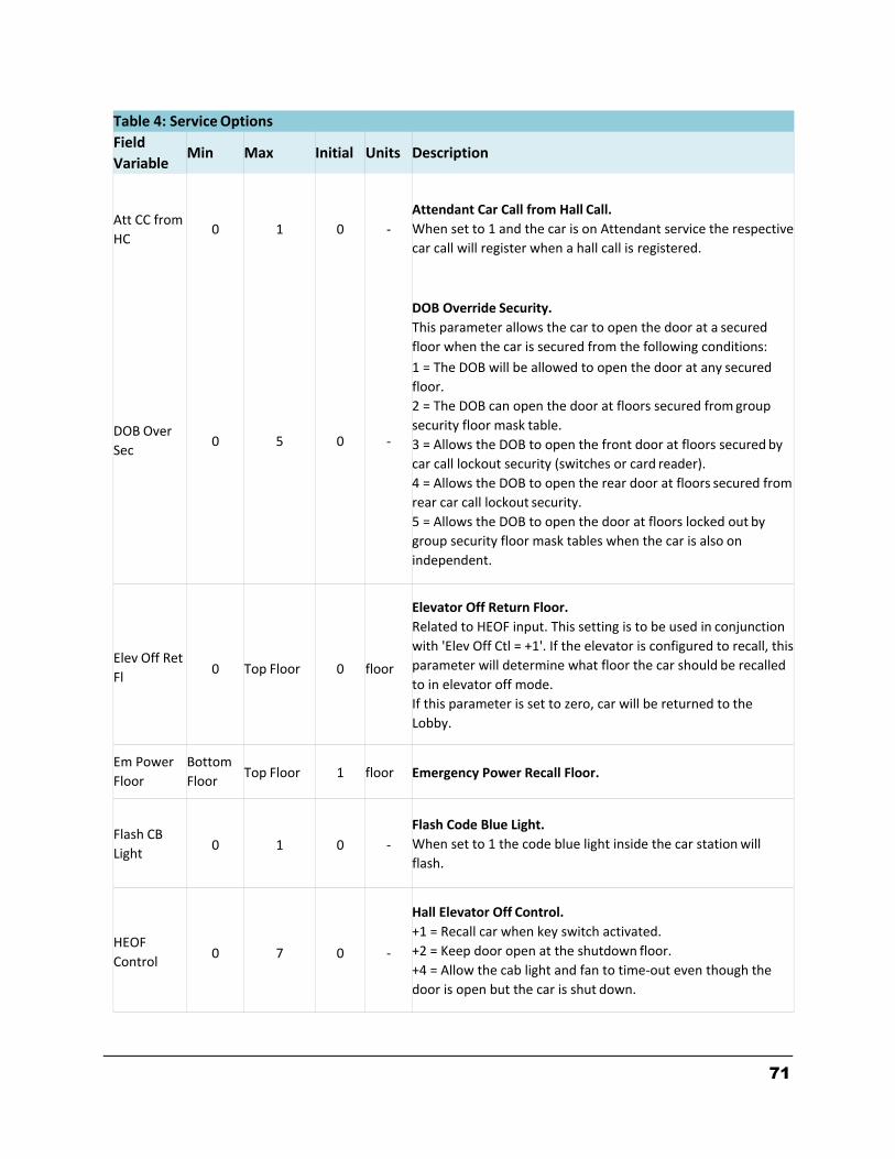
71
Table 4: Service Options
Field
Variable Min Max Initial Units Description
Att CC from
HC
0
1
0
‐
Attendant Car Call from Hall Call.
When set to 1 and the car is on Attendant service the respective
car call will register when a hall call is registered.
DOB Over
Sec
0
5
0
‐
DOB Override Security.
This parameter allows the car to open the door at a secured
floor when the car is secured from the following conditions:
1 = The DOB will be allowed to open the door at any secured
floor.
2 = The DOB can open the door at floors secured from group
security floor mask table.
3 = Allows the DOB to open the front door at floors secured by
car call lockout security (switches or card reader).
4 = Allows the DOB to open the rear door at floors secured from
rear car call lockout security.
5 = Allows the DOB to open the door at floors locked out by
group security floor mask tables when the car is also on
independent.
Elev Off Ret
Fl
0
Top Floor
0
floor
Elevator Off Return Floor.
Related to HEOF input. This setting is to be used in conjunction
with 'Elev Off Ctl = +1'. If the elevator is configured to recall, this
parameter will determine what floor the car should be recalled
to in elevator off mode.
If this parameter is set to zero, car will be returned to the
Lobby.
Em Power
Floor
Bottom
Floor
Top Floor
1
floor
Emergency Power Recall Floor.
Flash CB
Light
0
1
0
‐
Flash Code Blue Light.
When set to 1 the code blue light inside the car station will
flash.
HEOF
Control
0
7
0
‐
Hall Elevator Off Control.
+1 = Recall car when key switch activated.
+2 = Keep door open at the shutdown floor.
+4 = Allow the cab light and fan to time‐out even though the
door is open but the car is shut down.
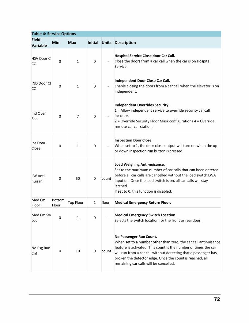
72
Table 4: Service Options
Field
Variable Min Max Initial Units Description
HSV Door Cl
CC
0
1
0
‐
Hospital Service Close door Car Call.
Close the doors from a car call when the car is on Hospital
Service.
IND Door Cl
CC
0
1
0
‐
Independent Door Close Car Call.
Enable closing the doors from a car call when the elevator is on
independent.
Ind Over
Sec
0
7
0
‐
Independent Overrides Security.
1 = Allow independent service to override security car call
lockouts.
2 = Override Security Floor Mask configurations 4 = Override
remote car call station.
Ins Door
Close
0
1
0
‐
Inspection Door Close.
When set to 1, the door close output will turn on when the up
or down inspection run button is pressed.
LW Anti‐
nuisan
0
50
0
count
Load Weighing Anti‐nuisance.
Set to the maximum number of car calls that can been entered
before all car calls are cancelled without the load switch LWA
input on. Once the load switch is on, all car calls will stay
latched.
If set to 0, this function is disabled.
Med Em
Floor
Bottom
Floor Top Floor 1 floor Medical Emergency Return Floor.
Med Em Sw
Loc
0
1
0
‐
Medical Emergency Switch Location.
Selects the switch location for the front or rear door.
No Psg Run
Cnt
0
10
0
count
No Passenger Run Count.
When set to a number other than zero, the car call antinuisance
feature is activated. This count is the number of times the car
will run from a car call without detecting that a passenger has
broken the detector edge. Once the count is reached, all
remaining car calls will be cancelled.
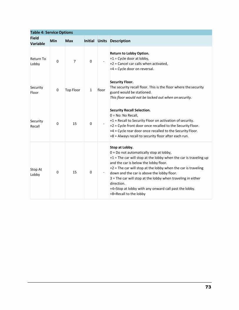
73
Table 4: Service Options
Field
Variable Min Max Initial Units Description
Return To
Lobby
0
7
0
‐
Return to Lobby Option.
+1 = Cycle door at lobby,
+2 = Cancel car calls when activated,
+4 = Cycle door on reversal.
Security
Floor
0
Top Floor
1
floor
Security Floor.
The security recall floor. This is the floor where the security
guard would be stationed.
This floor would not be locked out when on security.
Security
Recall
0
15
0
‐
Security Recall Selection.
0 = No: No Recall,
+1 = Recall to Security Floor on activation of security.
+2 = Cycle front door once recalled to the Security Floor.
+4 = Cycle rear door once recalled to the Security Floor.
+8 = Always recall to security floor after each run.
Stop At
Lobby
0
15
0
‐
Stop at Lobby.
0 = Do not automatically stop at lobby,
+1 = The car will stop at the lobby when the car is traveling up
and the car is below the lobby floor.
+2 = The car will stop at the lobby when the car is traveling
down and the car is above the lobby floor.
3 = The car will stop at the lobby when traveling in either
direction.
+4=Stop at lobby with any onward call past the lobby.
+8=Recall to the lobby
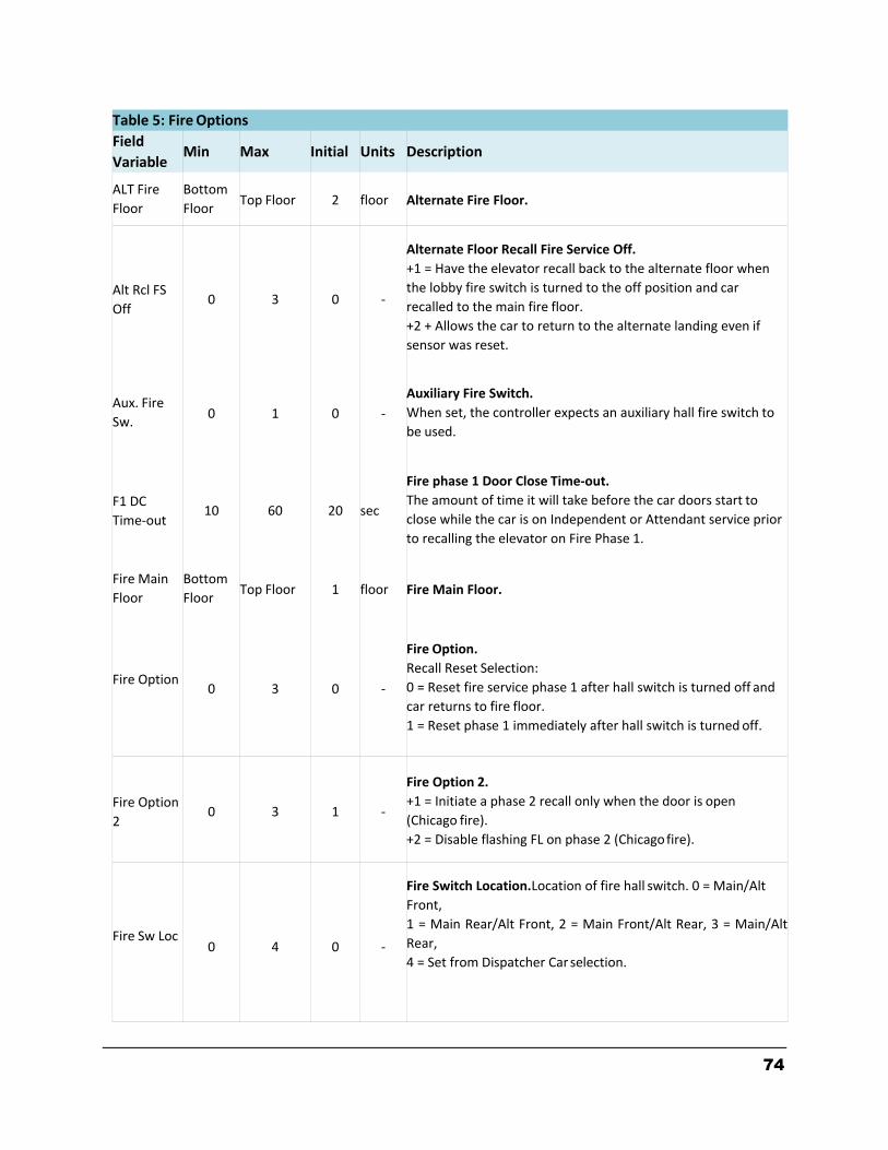
74
Table 5: Fire Options
Field
Variable Min Max Initial Units Description
ALT Fire
Floor
Bottom
Floor
Top Floor
2
floor
Alternate Fire Floor.
Alt Rcl FS
Off
0
3
0
‐
Alternate Floor Recall Fire Service Off.
+1 = Have the elevator recall back to the alternate floor when
the lobby fire switch is turned to the off position and car
recalled to the main fire floor.
+2 + Allows the car to return to the alternate landing even if
sensor was reset.
Aux. Fire
Sw.
0
1
0
‐
Auxiliary Fire Switch.
When set, the controller expects an auxiliary hall fire switch to
be used.
F1 DC
Time‐out
10
60
20
sec
Fire phase 1 Door Close Time‐out.
The amount of time it will take before the car doors start to
close while the car is on Independent or Attendant service prior
to recalling the elevator on Fire Phase 1.
Fire Main
Floor
Bottom
Floor
Top Floor
1
floor
Fire Main Floor.
Fire Option
0
3
0
‐
Fire Option.
Recall Reset Selection:
0 = Reset fire service phase 1 after hall switch is turned off and
car returns to fire floor.
1 = Reset phase 1 immediately after hall switch is turned off.
Fire Option
2
0
3
1
‐
Fire Option 2.
+1 = Initiate a phase 2 recall only when the door is open
(Chicago fire).
+2 = Disable flashing FL on phase 2 (Chicago fire).
Fire Sw Loc
0
4
0
‐
Fire Switch Location. Location of fire hall switch. 0 = Main/Alt
Front,
1 = Main Rear/Alt Front, 2 = Main Front/Alt Rear, 3 = Main/Alt
Rear,
4 = Set from Dispatcher Car selection.
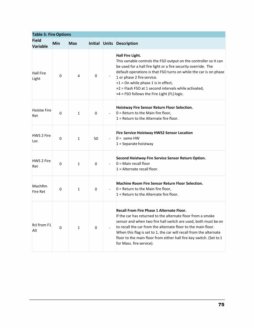
75
Table 5: Fire Options
Field
Variable Min Max Initial Units Description
Hall Fire
Light
0
4
0
‐
Hall Fire Light.
This variable controls the FSO output on the controller so it can
be used for a hall fire light or a fire security override. The
default operations is that FSO turns on while the car is on phase
1 or phase 2 fire service.
+1 = On while phase 1 is in effect,
+2 = Flash FSO at 1 second intervals while activated,
+4 = FSO follows the Fire Light (FL) logic.
Hoistw Fire
Ret
0
1
0
‐
Hoistway Fire Sensor Return Floor Selection.
0 = Return to the Main fire floor,
1 = Return to the Alternate fire floor.
HWS 2 Fire
Loc
0
1
50
‐
Fire Service Hoistway HWS2 Sensor Location
0 = same HW
1 = Separate hoistway
HWS 2 Fire
Ret
0
1
0
‐
Second Hoistway Fire Service Sensor Return Option.
0 = Main recall floor
1 = Alternate recall floor.
MachRm
Fire Ret
0
1
0
‐
Machine Room Fire Sensor Return Floor Selection.
0 = Return to the Main fire floor,
1 = Return to the Alternate fire floor.
Rcl from F1
Alt
0
1
0
‐
Recall From Fire Phase 1 Alternate Floor.
If the car has returned to the alternate floor from a smoke
sensor and when two fire hall switch are used, both must be on
to recall the car from the alternate floor to the main floor.
When this flag is set to 1, the car will recall from the alternate
floor to the main floor from either hall fire key switch. (Set to 1
for Mass. fire service).

76
Table 5: Fire Options
Field
Variable Min Max Initial Units Description
Recall
Reset
0
3
0
‐
Recall Reset Selection.
0 = Reset fire service phase 1 after hall switch cycled through
reset and turned off and car returns to fire floor.
1 = Reset phase 1 immediately after hall switch is cycled through
reset and then turned off.
2 = reset fire service without cycling fire switch through reset
but turned off only if the smoke sensors were not activated.

77
Table 6: Group Dispatch
Field
Variable Min Max Initial Units Description
Dn Pk Trig
Cnt
1
100
12
count
Down Peak Trigger Count.
Number of down hall calls above the lobby that are set within
the down peak trigger time to place the system on down peak
operation.
Dn Pk Trig
Time
0
3200
60
sec
Down Peak Trigger Time.
The time interval to count the number of down hall calls above
the lobby to activate down peak operation.
Down Peak
Time
0
3200
180
sec
Down Peak Duration Time.
The duration time for down peak operation once down peak is
activated.
ETA Co CC
Time
0
60
15
sec
ETA Coincident Car Call Time.
Hall calls will be assigned to the car with the coincident car call
unless the car without the coincident car call can reach the call
faster than ETA Coincident Car Call Time.
ETA Min
Time
0
60
6
sec
ETA Minimum Time.
For a hall call to be assigned to a new car, the difference in ETA
must be greater than the ETA Minimum Time.
Lobby Floor Bottom
Floor
Top Floor
1
floor
Lobby Floor.
Lobby Req
Cntrl
0
1
0
‐
Lobby Request Control.
If the lobby request variable is set to non‐zero, then that is
how many cars are requested to the lobby all the time. When
this flag is set to 1, the lobby request is only used when next up
is active. Next Up can be active all the time, from a dedicated
input or from Up Peak.

78
Table 6: Group Dispatch
Field
Variable Min Max Initial Units Description
Next Car Up
0
7
0
‐
Next Car Up.
Set to 1 or 2 will activate the Next Car Up operation.
1 = The next up car will open its door at the lobby and keep it
open. The car is allowed to leave the floor after the Lobby
Dwell time expires but will remain at the floor with the door
open until an onward call is assigned to it.
2 = The next up car will close its door after the Lobby Dwell
time expires and go off of next up but will remain at the lobby.
An up hall call at the lobby will cause the car to open its door
and go on next up.
4 = Next up is activated on Up Peak detection only. Next up can
also be activated from an input.
Park Delay
Time
0
120
8
sec
Parking Delay Time.
Time delay an idle car waits before being parked.
Parking
0
Number
Cars
1
car
Number of Cars to Park.
One car is parked at the lobby. The remaining cars are parked
at the most used floors of the building. If set to zero, no cars
are parked.
Parking
floor 1
0
Top Floor
0
floor
Parking Floor 1.
Floor to park the idle car. If set to zero, the group will use
number of hall call history to decide where to park the car. The
parking variable must be set to at least 1 for this function to
work. See also Parking Type.
Parking
Type
0
3
0
‐
Parking Type.
Determines the type of parking operation that is implemented
by the group.
0 = Park free cars to floors with the most hall calls for that 15
minute period.
1 = Divide the hoistway by the number of cars and place a car
in each zone starting with the lobby.
2 = Park cars according to the adjustable variable parking floor.
Note that during parking, a car is always parked at the Lobby
except when the option for alternate parking floor is selected
through an input.
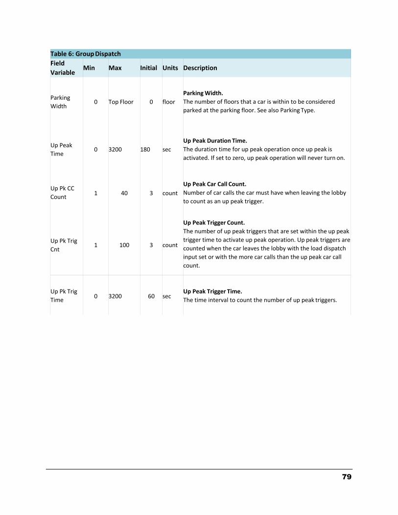
79
Table 6: Group Dispatch
Field
Variable Min Max Initial Units Description
Parking
Width
0
Top Floor
0
floor
Parking Width.
The number of floors that a car is within to be considered
parked at the parking floor. See also Parking Type.
Up Peak
Time
0
3200
180
sec
Up Peak Duration Time.
The duration time for up peak operation once up peak is
activated. If set to zero, up peak operation will never turn on.
Up Pk CC
Count
1
40
3
count
Up Peak Car Call Count.
Number of car calls the car must have when leaving the lobby
to count as an up peak trigger.
Up Pk Trig
Cnt
1
100
3
count
Up Peak Trigger Count.
The number of up peak triggers that are set within the up peak
trigger time to activate up peak operation. Up peak triggers are
counted when the car leaves the lobby with the load dispatch
input set or with the more car calls than the up peak car call
count.
Up Pk Trig
Time
0
3200
60
sec
Up Peak Trigger Time.
The time interval to count the number of up peak triggers.
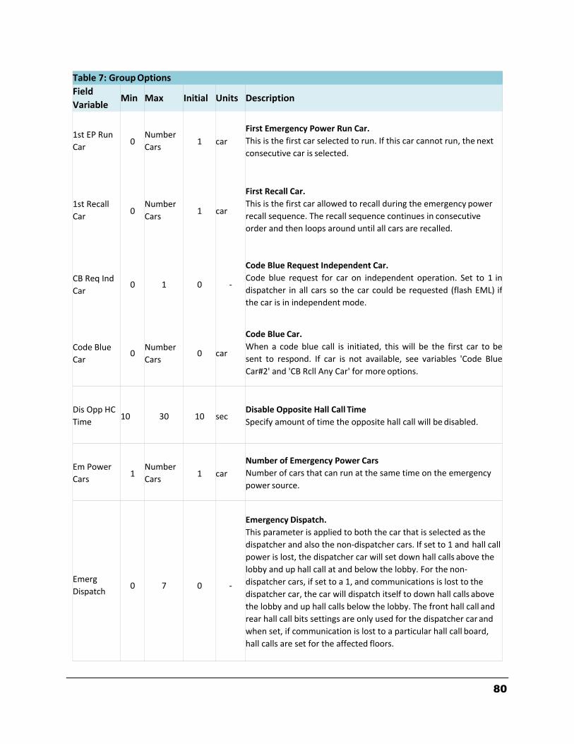
80
Table 7: Group Options
Field
Variable Min Max Initial Units Description
1st EP Run
Car
0
Number
Cars
1
car
First Emergency Power Run Car.
This is the first car selected to run. If this car cannot run, the next
consecutive car is selected.
1st Recall
Car
0
Number
Cars
1
car
First Recall Car.
This is the first car allowed to recall during the emergency power
recall sequence. The recall sequence continues in consecutive
order and then loops around until all cars are recalled.
CB Req Ind
Car
0
1
0
‐
Code Blue Request Independent Car.
Code blue request for car on independent operation. Set to 1 in
dispatcher in all cars so the car could be requested (flash EML) if
the car is in independent mode.
Code Blue
Car
0
Number
Cars
0
car
Code Blue Car.
When a code blue call is initiated, this will be the first car to be
sent to respond. If car is not available, see variables 'Code Blue
Car#2' and 'CB Rcll Any Car' for more options.
Dis Opp HC
Time
10
30
10
sec
Disable Opposite Hall Call Time
Specify amount of time the opposite hall call will be disabled.
Em Power
Cars
1
Number
Cars
1
car
Number of Emergency Power Cars
Number of cars that can run at the same time on the emergency
power source.
Emerg
Dispatch
0
7
0
‐
Emergency Dispatch.
This parameter is applied to both the car that is selected as the
dispatcher and also the non‐dispatcher cars. If set to 1 and hall call
power is lost, the dispatcher car will set down hall calls above the
lobby and up hall call at and below the lobby. For the non‐
dispatcher cars, if set to a 1, and communications is lost to the
dispatcher car, the car will dispatch itself to down hall calls above
the lobby and up hall calls below the lobby. The front hall call and
rear hall call bits settings are only used for the dispatcher car and
when set, if communication is lost to a particular hall call board,
hall calls are set for the affected floors.
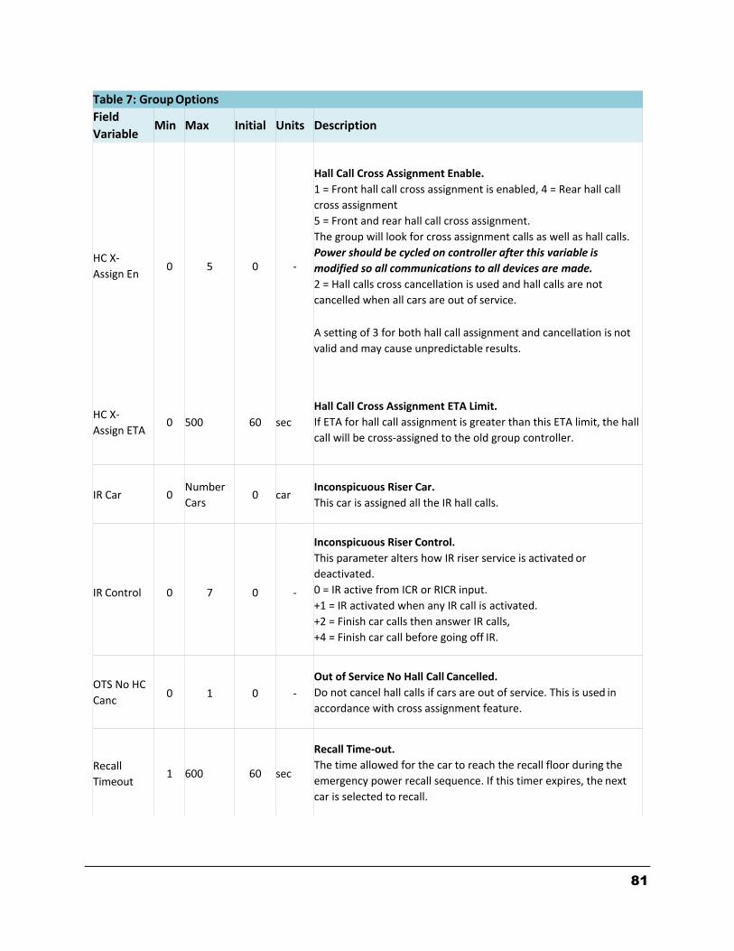
81
Table 7: Group Options
Field
Variable Min Max Initial Units Description
HC X‐
Assign En
0
5
0
‐
Hall Call Cross Assignment Enable.
1 = Front hall call cross assignment is enabled, 4 = Rear hall call
cross assignment
5 = Front and rear hall call cross assignment.
The group will look for cross assignment calls as well as hall calls.
Power should be cycled on controller after this variable is
modified so all communications to all devices are made.
2 = Hall calls cross cancellation is used and hall calls are not
cancelled when all cars are out of service.
A setting of 3 for both hall call assignment and cancellation is not
valid and may cause unpredictable results.
HC X‐
Assign ETA
0
500
60
sec
Hall Call Cross Assignment ETA Limit.
If ETA for hall call assignment is greater than this ETA limit, the hall
call will be cross‐assigned to the old group controller.
IR Car
0
Number
Cars
0
car
Inconspicuous Riser Car.
This car is assigned all the IR hall calls.
IR Control
0
7
0
‐
Inconspicuous Riser Control.
This parameter alters how IR riser service is activated or
deactivated.
0 = IR active from ICR or RICR input.
+1 = IR activated when any IR call is activated.
+2 = Finish car calls then answer IR calls,
+4 = Finish car call before going off IR.
OTS No HC
Canc
0
1
0
‐
Out of Service No Hall Call Cancelled.
Do not cancel hall calls if cars are out of service. This is used in
accordance with cross assignment feature.
Recall
Timeout
1
600
60
sec
Recall Time‐out.
The time allowed for the car to reach the recall floor during the
emergency power recall sequence. If this timer expires, the next
car is selected to recall.
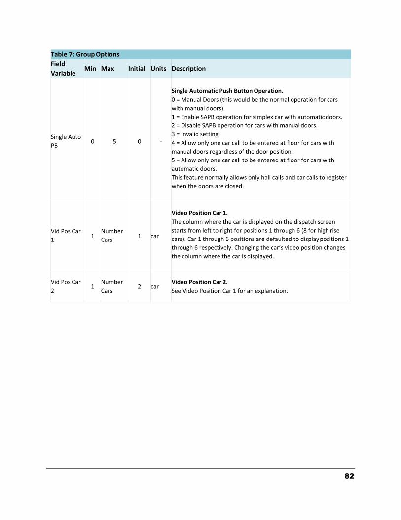
82
Table 7: Group Options
Field
Variable Min Max Initial Units Description
Single Auto
PB
0
5
0
‐
Single Automatic Push Button Operation.
0 = Manual Doors (this would be the normal operation for cars
with manual doors).
1 = Enable SAPB operation for simplex car with automatic doors.
2 = Disable SAPB operation for cars with manual doors.
3 = Invalid setting.
4 = Allow only one car call to be entered at floor for cars with
manual doors regardless of the door position.
5 = Allow only one car call to be entered at floor for cars with
automatic doors.
This feature normally allows only hall calls and car calls to register
when the doors are closed.
Vid Pos Car
1
1
Number
Cars
1
car
Video Position Car 1.
The column where the car is displayed on the dispatch screen
starts from left to right for positions 1 through 6 (8 for high rise
cars). Car 1 through 6 positions are defaulted to display positions 1
through 6 respectively. Changing the car’s video position changes
the column where the car is displayed.
Vid Pos Car
2
1
Number
Cars
2
car
Video Position Car 2.
See Video Position Car 1 for an explanation.
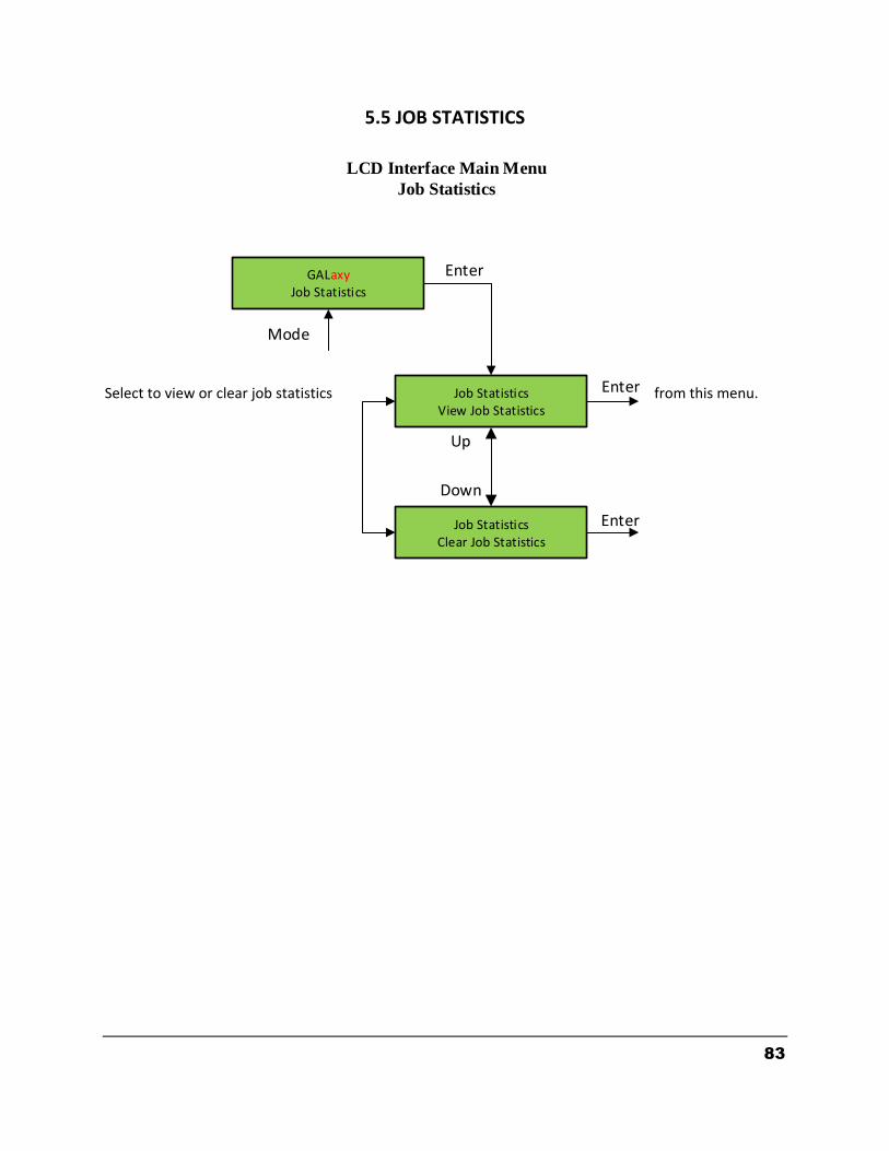
83
5.5 JOB STATISTICS Select to view or clear job statistics from this menu.
LCD Interface Main Menu
Job Statistics
GALaxyJob Statistics
Job StatisticsView Job Statistics
Job StatisticsClear Job Statistics
Up
Down
Enter
Mode
Enter
Enter
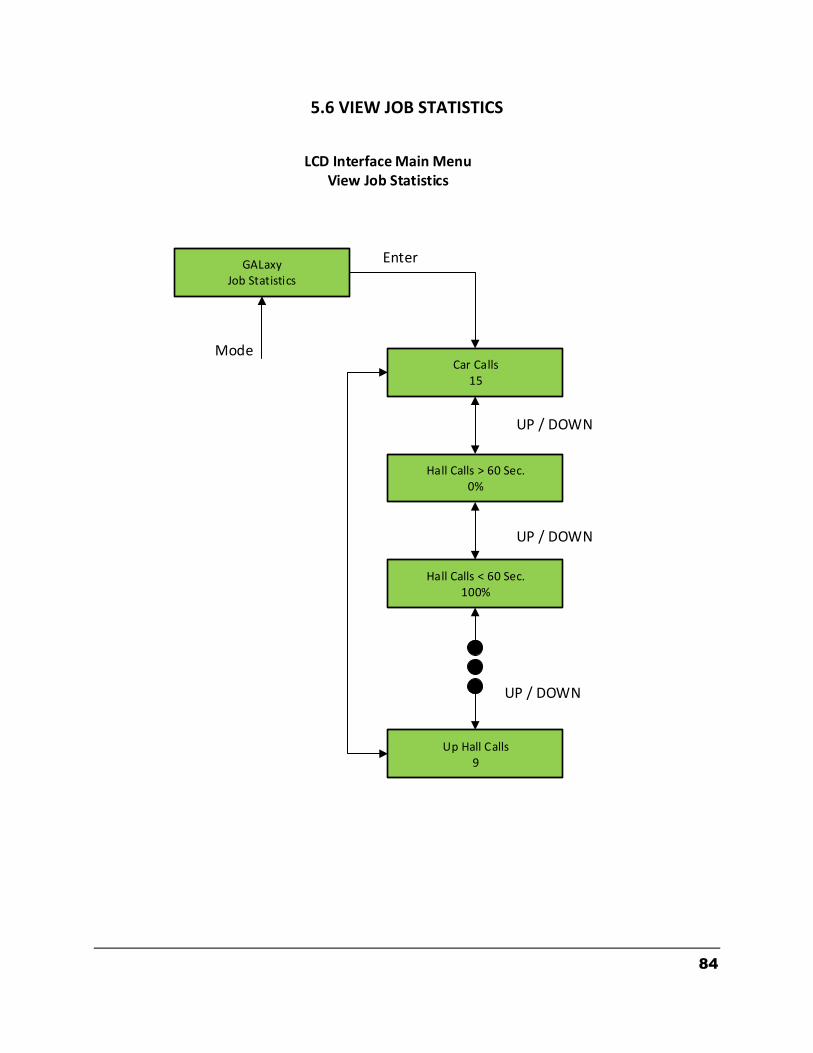
84
5.6 VIEW JOB STATISTICS
LCD Interface Main MenuView Job Statistics
GALaxyJob Statistics
Car Calls15
Hall Calls > 60 Sec.0%
Hall Calls < 60 Sec.100%
Up Hall Calls9
Mode
Enter
UP / DOWN
UP / DOWN
UP / DOWN

85
The Job Statistics shows the number car calls and the number and percent of hall calls serviced since the job was started or since the job statistics were cleared. Below is a list of all the categories maintained:
Number of Car Calls
Number of Up Hall Calls
Number of Down Hall Calls
Number of Up Hall Calls with < 15 second wait time
Number of Up Hall Calls with < 30 second wait time
Number of Up Hall Calls with < 45 second wait time
Number of Up Hall Calls with < 60 second wait time
Number of Up Hall Calls with > 60 second wait time
Number of Down Hall Calls with < 15 second wait time
Number of Down Hall Calls with < 30 second wait time
Number of Down Hall Calls with < 45 second wait time
Number of Down Hall Calls with < 60 second wait time
Number of Down Hall Calls with > 60 second wait time
Percent of Hall Calls with < 15 second wait time
Percent of Hall Calls with < 30 second wait time
Percent of Hall Calls with < 45 second wait time
Percent of Hall Calls with < 60 second wait time
Percent of Hall Calls with > 60 second wait time
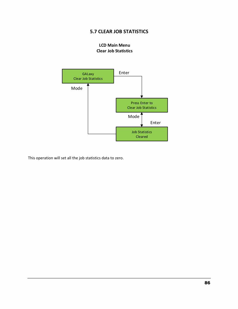
86
5.7 CLEAR JOB STATISTICS This operation will set all the job statistics data to zero.
GALaxyClear Job Statistics
Press Enter toClear Job Statistics
Job StatisticsCleared
Enter
Enter
Mode
Mode
LCD Main MenuClear Job Statistics
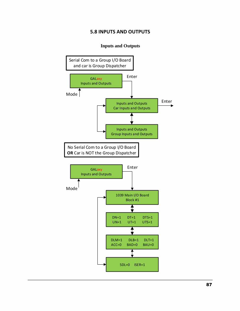
87
5.8 INPUTS AND OUTPUTS
Inputs and Outputs
GALaxyInputs and Outputs
Inputs and OutputsCar Inputs and Outputs
Inputs and OutputsGroup Inputs and Outputs
1039 Main I/O BoardBlock #1
DN=1 DT=1 DTS=1UN=1 UT=1 UTS=1
DLM=1 DLB=1 DLT=1ACC=0 BAD=0 BAU=0
5DL=0 ISER=1
GALaxyInputs and Outputs
Enter
Enter
Mode
Mode
Serial Com to a Group I/O Boardand car is Group Dispatcher
No Serial Com to a Group I/O Board OR Car is NOT the Group Dispatcher
Enter
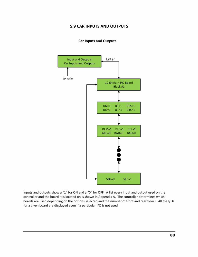
88
5.9 CAR INPUTS AND OUTPUTS Inputs and outputs show a “1” for ON and a “0” for OFF. A list every input and output used on the controller and the board it is located on is shown in Appendix A. The controller determines which boards are used depending on the options selected and the number of front and rear floors. All the I/Os for a given board are displayed even if a particular I/O is not used.
Input and OutputsCar Inputs and Outputs
1039 Main I/O BoardBlock #1
DN=1 DT=1 DTS=1UN=1 UT=1 UTS=1
DLM=1 DLB=1 DLT=1ACC=0 BAD=0 BAU=0
5DL=0 ISER=1
Enter
Mode
Car Inputs and Outputs
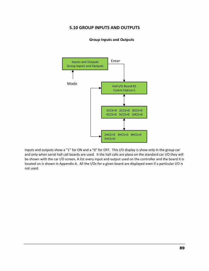
89
5.10 GROUP INPUTS AND OUTPUTS
Inputs and OutputsGroup Inputs and Outputs
Hall I/O Board #1Comm Status=1
1CCS=0 2CCS=0 3CCS=04CCS=0 5CCS=0 1HCS=0
2HCS=0 3HCS=0 4HCS=0 5HCS=0
Enter
Mode
Group Inputs and Outputs
Inputs and outputs show a “1” for ON and a “0” for OFF. This I/O display is show only in the group car and only when serial hall call boards are used. It the hall calls are place on the standard car I/O they will be shown with the car I/O screen. A list every input and output used on the controller and the board it is located on is shown in Appendix A. All the I/Os for a given board are displayed even if a particular I/O is not used.
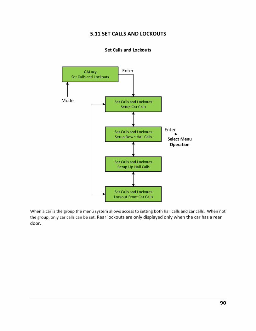
90
5.11 SET CALLS AND LOCKOUTS
GALaxySet Calls and Lockouts
Set Calls and LockoutsSetup Car Calls
Set Calls and LockoutsSetup Down Hall Calls
Set Calls and LockoutsSetup Up Hall Calls
Set Calls and LockoutsLockout Front Car Calls
Enter
Mode
Enter
Select Menu Operation
Set Calls and Lockouts
When a car is the group the menu system allows access to setting both hall calls and car calls. When not
the group, only car calls can be set. Rear lockouts are only displayed only when the car has a rear door.
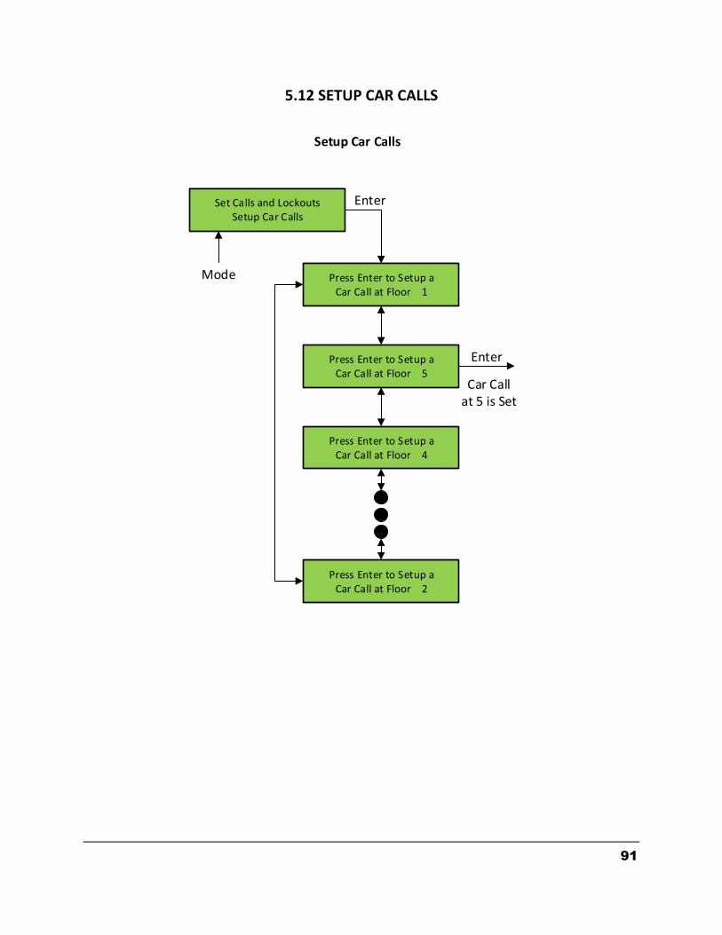
91
5.12 SETUP CAR CALLS
Set Calls and LockoutsSetup Car Calls
Press Enter to Setup a Car Call at Floor 1
Press Enter to Setup a Car Call at Floor 5
Press Enter to Setup a Car Call at Floor 4
Press Enter to Setup a Car Call at Floor 2
Enter
Mode
Enter
Car Callat 5 is Set
Setup Car Calls
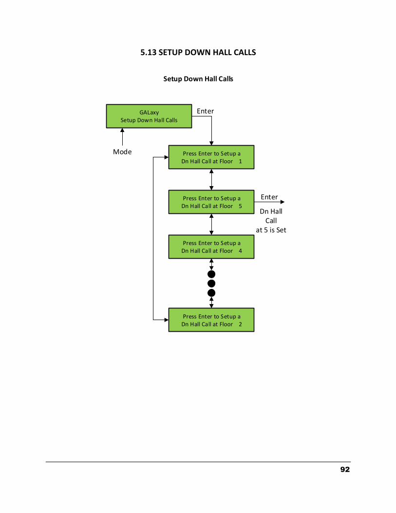
92
5.13 SETUP DOWN HALL CALLS
GALaxySetup Down Hall Calls
Press Enter to Setup a Dn Hall Call at Floor 1
Press Enter to Setup a Dn Hall Call at Floor 5
Press Enter to Setup a Dn Hall Call at Floor 4
Press Enter to Setup a Dn Hall Call at Floor 2
Enter
Mode
Enter
Dn Hall Call
at 5 is Set
Setup Down Hall Calls
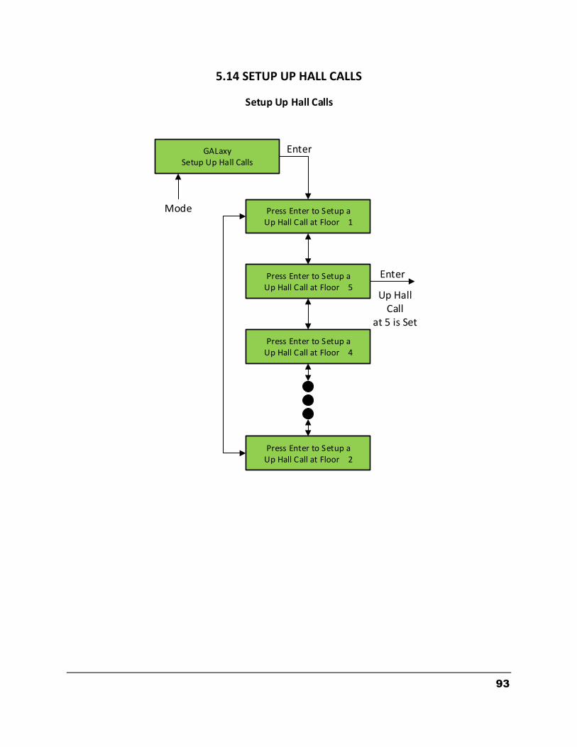
93
5.14 SETUP UP HALL CALLS
GALaxySetup Up Hall Calls
Press Enter to Setup a Up Hall Call at Floor 1
Press Enter to Setup a Up Hall Call at Floor 5
Press Enter to Setup a Up Hall Call at Floor 4
Press Enter to Setup a Up Hall Call at Floor 2
Enter
Mode
Enter
Up Hall Call
at 5 is Set
Setup Up Hall Calls

94
5.15 LOCKOUT FRONT CAR CALL
Set Calls and LockoutsLockout Front Car Calls
Press Enter to ModifyFront CC Access: L
Press Enter to ModifyFront CC Access: 5*
Press Enter to ModifyFront CC Access: 4
Press Enter to ModifyFront CC Access: 2
Enter
Mode
Enter
Lockout Front Car Calls
Press Enter to toggle lockout on
and off.
(*) Asterisk appears when Car Call is locked out.

95
5.16 ELEVATOR STATUS
The elevator status display continuously updates to show the current status and fault information. When a system fault occurs, it will be displayed on the top line of the status display while the fault exist and will remain for 60 seconds after the fault is cleared. The following status information can be displayed:
Elevator Service: Out of Service Automatic Service Independent Service Load Weighing By Pass Attendant Service Code Blue Service Fire Service Phase 2 Emergency Power Service Earth Quake Service Fire Phase 1 Main Return Fire Phase 1 Alt Return Homing Reset Going Up Reset Going Down Stalled Out of Service
Fault Status: Reset Fault Out of Step Fault Binary Input Fault
GALaxyElevator Status
Automatic ServiceWaiting Assignment PI=L
Enter
Mode
Elevator Status
Car Service
Car Status
Floor Position

96
Safety String Fault Door Zone Fault Stalled Fault Door Open Fault Door Close Fault Up Directional Fault Dn Directional Fault No Potential Fault Stop Switch Fault Gate or Interlock LC Fuse Blown Fault HC Fuse Blown Fault Drive Ready Fault Car Safe Fault UL or DL off Fault Delta off Fault UT count Fault DT count Fault Group Comm Loss Car 1 Comm Loss Car 2 Comm Loss Car 3 Comm Loss Car 4 Comm Loss Car 5 Comm Loss Car 6 Comm Loss RUN I/O Failed ON RUN I/O Failed OFF RUNA I/O Failed ON RUNA I/O Failed OFF UP I/O Failed ON UP I/O Failed OFF DNR I/O Failed ON DNR I/O Failed OFF UPF I/O Failed ON UPF I/O Failed OFF DF I/O Failed ON DF I/O Failed OFF MCC I/O Failed ON MCC I/O Failed OFF MCA I/O Failed ON MCA I/O Failed OFF BRK I/O Failed ON BRK I/O Failed OFF
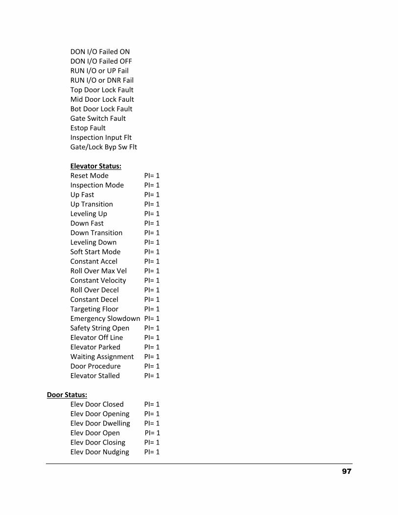
97
DON I/O Failed ON DON I/O Failed OFF RUN I/O or UP Fail RUN I/O or DNR Fail Top Door Lock Fault Mid Door Lock Fault Bot Door Lock Fault Gate Switch Fault Estop Fault Inspection Input Flt Gate/Lock Byp Sw Flt Elevator Status:
Reset Mode PI= 1 Inspection Mode PI= 1 Up Fast PI= 1 Up Transition PI= 1 Leveling Up PI= 1 Down Fast PI= 1 Down Transition PI= 1 Leveling Down PI= 1 Soft Start Mode PI= 1 Constant Accel PI= 1 Roll Over Max Vel PI= 1 Constant Velocity PI= 1 Roll Over Decel PI= 1 Constant Decel PI= 1 Targeting Floor PI= 1 Emergency Slowdown PI= 1 Safety String Open PI= 1 Elevator Off Line PI= 1 Elevator Parked PI= 1 Waiting Assignment PI= 1 Door Procedure PI= 1 Elevator Stalled PI= 1 Door Status:
Elev Door Closed PI= 1 Elev Door Opening PI= 1 Elev Door Dwelling PI= 1 Elev Door Open PI= 1 Elev Door Closing PI= 1 Elev Door Nudging PI= 1
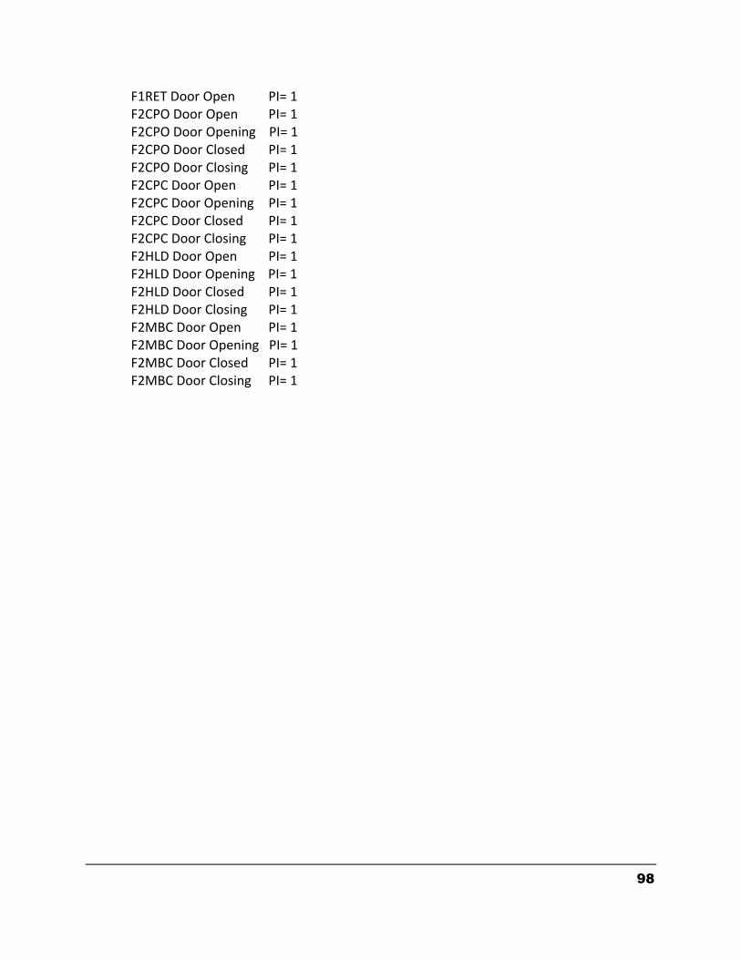
98
F1RET Door Open PI= 1 F2CPO Door Open PI= 1 F2CPO Door Opening PI= 1 F2CPO Door Closed PI= 1 F2CPO Door Closing PI= 1 F2CPC Door Open PI= 1 F2CPC Door Opening PI= 1 F2CPC Door Closed PI= 1 F2CPC Door Closing PI= 1 F2HLD Door Open PI= 1 F2HLD Door Opening PI= 1 F2HLD Door Closed PI= 1 F2HLD Door Closing PI= 1 F2MBC Door Open PI= 1 F2MBC Door Opening PI= 1 F2MBC Door Closed PI= 1 F2MBC Door Closing PI= 1
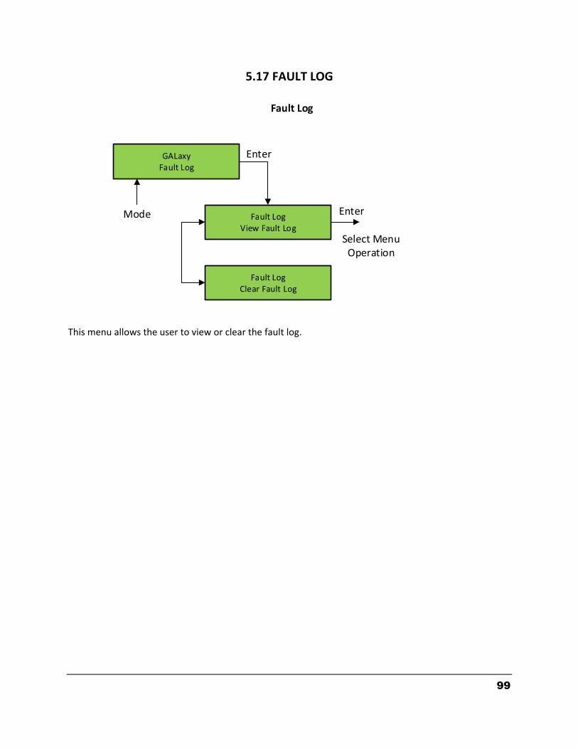
99
5.17 FAULT LOG This menu allows the user to view or clear the fault log.
GALaxyFault Log
Fault LogView Fault Log
Enter
Mode
Fault Log
Fault LogClear Fault Log
Enter
Select MenuOperation
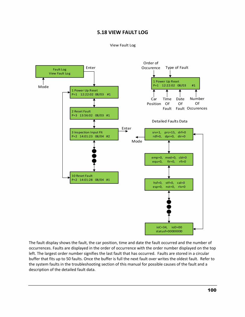
100
Fault LogView Fault Log
1 Power Up ResetP=1 12:22:02 08/03 #1
2 Reset FaultP=3 13:56:02 08/03 #1
3 Inspection Input FltP=2 14:01:23 08/04 #2
10 Reset FaultP=2 14:01:28 08/04 #1
srv=1, prc=15, drf=0rdf=0, dpr=0, dir=0
emp=0, med=0, cbl=0equ=0, fir=0, rfi=0
1 Power Up ResetP=1 12:22:02 08/03 #1
hsf=0, stf=0, cal=0esp=0, nst=0, rlv=0
ioC=34, ioD=00statusf=00000000
Enter
Enter
Mode
Mode
Detailed Faults Data
Order ofOccurence Type of Fault
CarPosition
TimeOf
Fault
DateOf
Fault
NumberOf
Occurences
View Fault Log
5.18 VIEW FAULT LOG
The fault display shows the fault, the car position, time and date the fault occurred and the number of occurrences. Faults are displayed in the order of occurrence with the order number displayed on the top left. The largest order number signifies the last fault that has occurred. Faults are stored in a circular buffer that fits up to 50 faults. Once the buffer is full the next fault over writes the oldest fault. Refer to the system faults in the troubleshooting section of this manual for possible causes of the fault and a description of the detailed fault data.
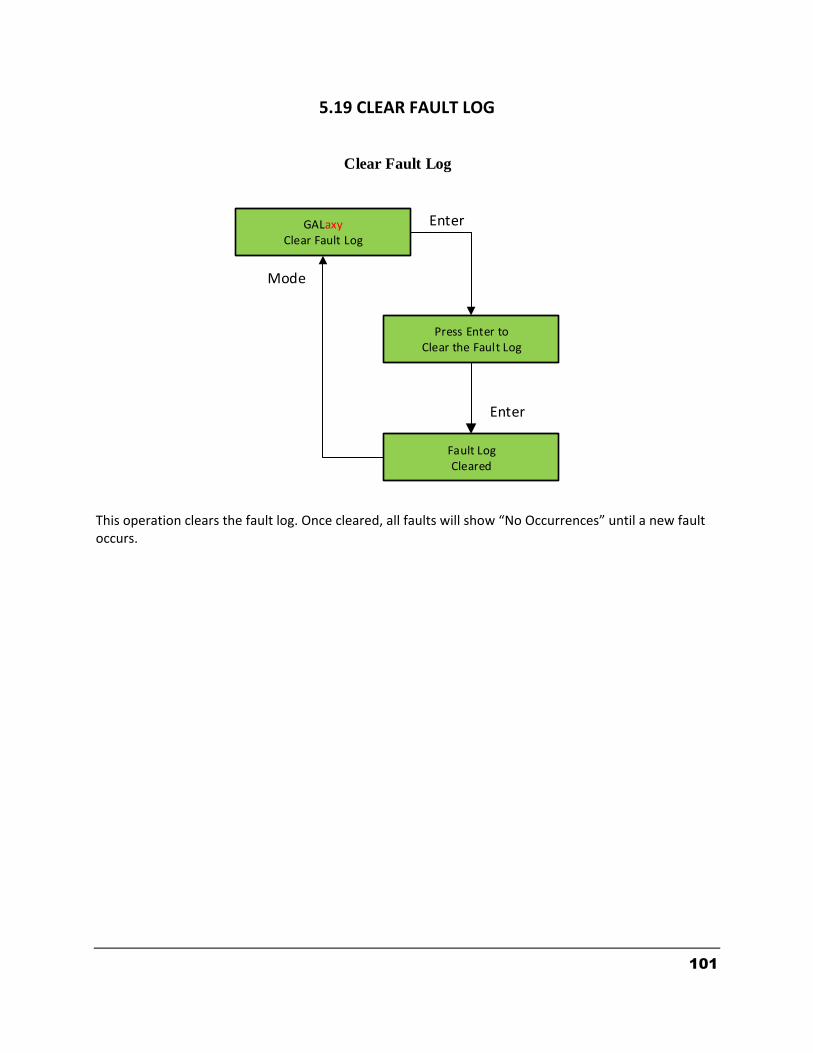
101
5.19 CLEAR FAULT LOG This operation clears the fault log. Once cleared, all faults will show “No Occurrences” until a new fault occurs.
Clear Fault Log
GALaxyClear Fault Log
Press Enter toClear the Fault Log
Fault LogCleared
Enter
Mode
Enter

102
5.20 RESET LOW/HOT OIL
GALaxyElevator Setup
Elevator SetupReset Low Oil
Reset Low OilCar must be on Inspect
Press Enter ButtonTo reset Low Oil
Low Oil OperationIs Reset
Enter
Enter
Enter
Enter
Mode
NOTE: Reset Hot Oil is similar.
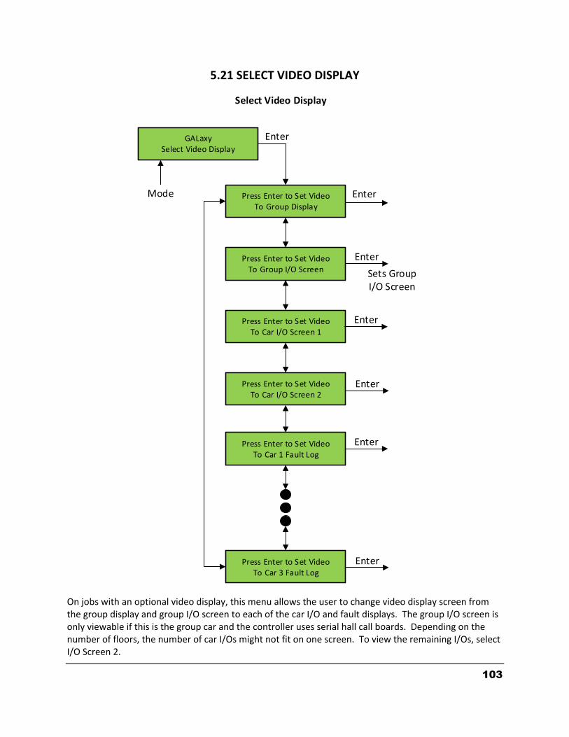
103
5.21 SELECT VIDEO DISPLAY On jobs with an optional video display, this menu allows the user to change video display screen from the group display and group I/O screen to each of the car I/O and fault displays. The group I/O screen is only viewable if this is the group car and the controller uses serial hall call boards. Depending on the number of floors, the number of car I/Os might not fit on one screen. To view the remaining I/Os, select I/O Screen 2.
GALaxySelect Video Display
Press Enter to Set VideoTo Group Display
Press Enter to Set VideoTo Group I/O Screen
Press Enter to Set VideoTo Car I/O Screen 1
Press Enter to Set VideoTo Car 3 Fault Log
Enter
Mode
Enter
Select Video Display
Press Enter to Set VideoTo Car I/O Screen 2
Press Enter to Set VideoTo Car 1 Fault Log
Sets Group I/O Screen
Enter
Enter
Enter
Enter
Enter
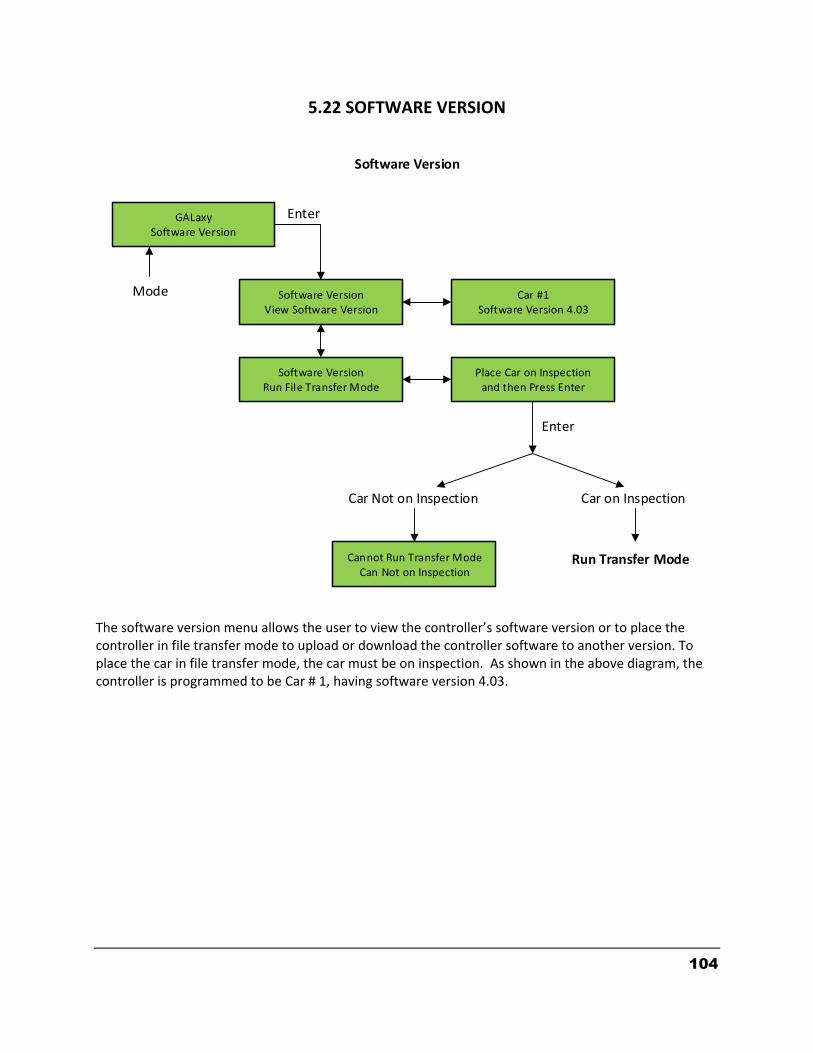
104
GALaxySoftware Version
Software VersionView Software Version
Software VersionRun File Transfer Mode
Car #1Software Version 4.03
Place Car on Inspectionand then Press Enter
Cannot Run Transfer ModeCan Not on Inspection
Software Version
Car Not on Inspection Car on Inspection
Run Transfer Mode
Enter
Enter
Mode
5.22 SOFTWARE VERSION
The software version menu allows the user to view the controller’s software version or to place the controller in file transfer mode to upload or download the controller software to another version. To place the car in file transfer mode, the car must be on inspection. As shown in the above diagram, the controller is programmed to be Car # 1, having software version 4.03.
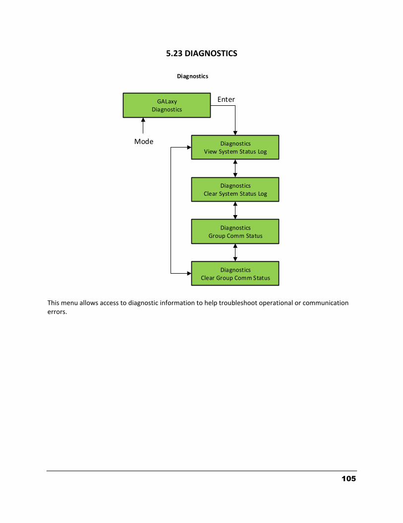
105
5.23 DIAGNOSTICS This menu allows access to diagnostic information to help troubleshoot operational or communication errors.
GALaxyDiagnostics
DiagnosticsView System Status Log
DiagnosticsClear System Status Log
Diagnostics
Enter
Mode
DiagnosticsGroup Comm Status
DiagnosticsClear Group Comm Status

106
5.24 VIEW SYSTEM STATUS LOG
System status information is stored in a circular buffer whenever the service, elevator status or a fault occurs. This buffer holds 256 blocks of data in the sequence in which the events occur. This data can be used to debug a sequence of events that cause a fault. The most recent block of information is always at location 000 and the event prior to the most recent is at block location –001. The event at block –002 happened before block –001 and also before block 000.
GALaxyView System Status Log
000 Status Buffer PI=1Automatic Service
000 Status Buffer PI=1Waiting Assignment
000 Status Buffer PI=1Status OK
-256 Status Buffer PI=1No Data Logged
Enter
Mode
View System Status Log
000 Status Buffer PI=1NoFaults
-001 Status Buffer PI=1Automatic Service
-001 Status Buffer PI=1Waiting Assignment
-001 Status Buffer PI=1Status OK
-001 Status Buffer PI=1Reset Fault
BlockOf4
BlockOf4
-001 Status Buffer PI=1Reset Fault
Buffer Index Floor Position
Service, Elevator Status,Condition Status, or Fault
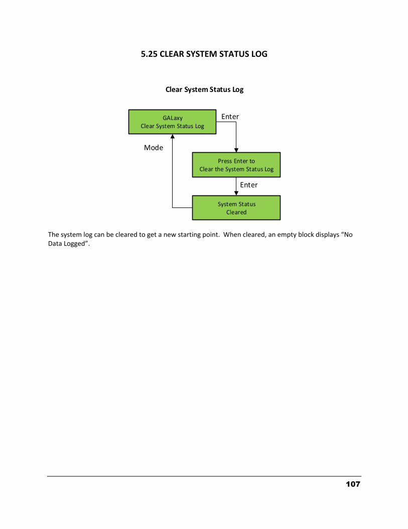
107
5.25 CLEAR SYSTEM STATUS LOG The system log can be cleared to get a new starting point. When cleared, an empty block displays “No Data Logged”.
GALaxyClear System Status Log
Press Enter toClear the System Status Log
Enter
Mode
Clear System Status Log
System StatusCleared
Enter

108
5.26 GROUP COMM STATUS
Group Comm Status
GALaxyGroup Comm Status
Group to Car #1Internal Comm
Group to Car # 2txCnt 3155 RxCnt 3154
Car # 2 to GroupTxCnt 10132 RxCnt 10132
GALaxyGroup Comm Status
Enter
Enter
Mode
Mode
Car is Group Dispatcher
Car is NOT Group Dispatcher
Enter
Group to Car # 3TxCnt 3196 RxCnt 3195
UpdatesCount
Group to Car # 3TxCnt 3196 RxCnt 3195
Name of Comm Device
Transmit Count Receive Count
Enter
UpdatesCount
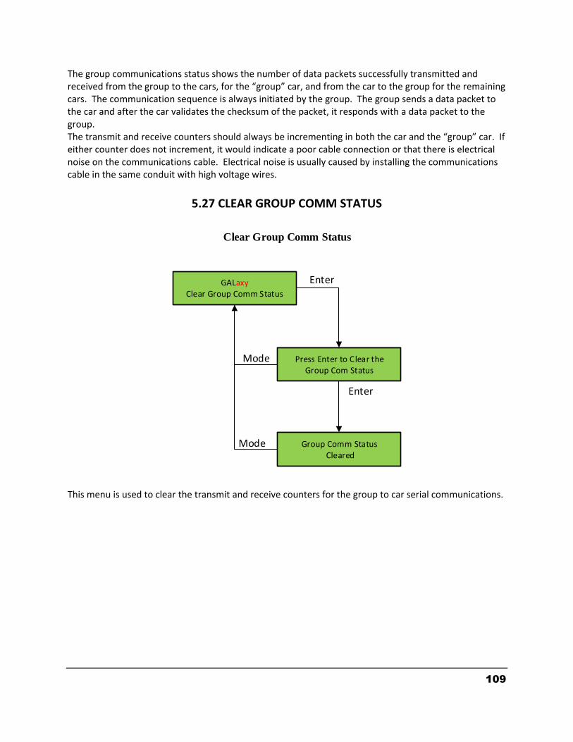
109
The group communications status shows the number of data packets successfully transmitted and received from the group to the cars, for the “group” car, and from the car to the group for the remaining cars. The communication sequence is always initiated by the group. The group sends a data packet to the car and after the car validates the checksum of the packet, it responds with a data packet to the group. The transmit and receive counters should always be incrementing in both the car and the “group” car. If either counter does not increment, it would indicate a poor cable connection or that there is electrical noise on the communications cable. Electrical noise is usually caused by installing the communications cable in the same conduit with high voltage wires.
5.27 CLEAR GROUP COMM STATUS This menu is used to clear the transmit and receive counters for the group to car serial communications.
Clear Group Comm Status
GALaxyClear Group Comm Status
Press Enter to Clear theGroup Com Status
Group Comm Status Cleared
Enter
Mode
Mode
Enter
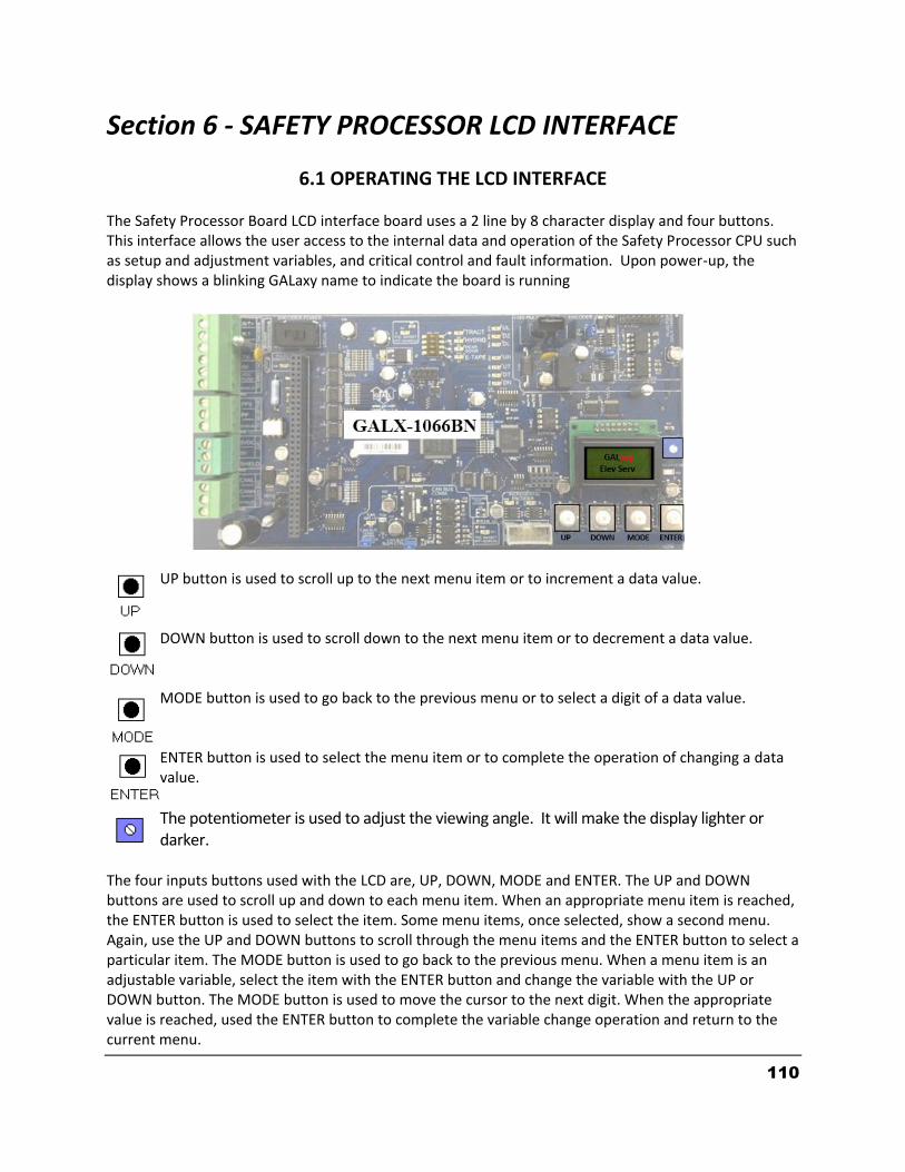
110
Section 6 - SAFETY PROCESSOR LCD INTERFACE
6.1 OPERATING THE LCD INTERFACE The Safety Processor Board LCD interface board uses a 2 line by 8 character display and four buttons. This interface allows the user access to the internal data and operation of the Safety Processor CPU such as setup and adjustment variables, and critical control and fault information. Upon power-up, the display shows a blinking GALaxy name to indicate the board is running
UP button is used to scroll up to the next menu item or to increment a data value.
DOWN button is used to scroll down to the next menu item or to decrement a data value.
MODE button is used to go back to the previous menu or to select a digit of a data value.
ENTER button is used to select the menu item or to complete the operation of changing a data value.
The potentiometer is used to adjust the viewing angle. It will make the display lighter or darker.
The four inputs buttons used with the LCD are, UP, DOWN, MODE and ENTER. The UP and DOWN buttons are used to scroll up and down to each menu item. When an appropriate menu item is reached, the ENTER button is used to select the item. Some menu items, once selected, show a second menu. Again, use the UP and DOWN buttons to scroll through the menu items and the ENTER button to select a particular item. The MODE button is used to go back to the previous menu. When a menu item is an adjustable variable, select the item with the ENTER button and change the variable with the UP or DOWN button. The MODE button is used to move the cursor to the next digit. When the appropriate value is reached, used the ENTER button to complete the variable change operation and return to the current menu.

111
6.2 THE SAFETY PROCESSOR BOARD LCD MENU STRUCTURE
GALaxyPls Cnt
GALaxyCar Com
GALaxyCar Spd
GALaxyElev Serv
GALaxyExt Temp
GALaxyBrd Temp
GALaxyAdj var
GALaxyInp/Out
GALaxyLim Vel
GALaxyFaults
GALaxyClr Flts
GALaxyReset
Power Up
Safety Processor LCD Display Menu

112
6.3 ELEVATOR SERVICE This screen shows the service the car should be on from the inspection inputs, the gate and lock bypass switch inputs and the gate and lock inputs. If any inputs are in error, the error status is displayed. Below shows a list of what is displayed and the condition for it.
ELEVATOR SERVICE CONDITION FOR SERVICE AUTO Auto input is on and all inspection inputs are off.
CT INS Car is on car top inspection
GATE BYP Car is on car top inspection and the gate bypass switch is on.
LOCK BYP Car is on car top inspection and the lock bypass switch is on.
ACCESS Car is on access operation.
MR INS Car is on motor room inspection.
IC INS Car is on in car inspection
INS ERR An inspection error has occurred. There must be one and only one inspection or auto input on. All inputs are off or more than one input is on.
BYP ERR A gate or lock bypass switch is on but the car is not on car top inspection.
VEL ERR The car has a velocity error from inspection speed, leveling speed or a terminal slowdown speed.
UP ERR The up output is on during power up.
DNR ERR The down output is on during power up.
DNR/UP Both up and down outputs are on during power up.
EEP ERR Safety Processor board has an EEPROM error.
NO UTS UTS input not detected at top terminal landing.
NO DTS DTS input not detected at bottom terminal landing.
GALaxyElev Serv
MR INSOpen UP
Enter
Mode
Car Status
Door Status Car Direction
Elevator Service

113
6.4 CAR SPEED
6.5 SAFETY PROCESSOR PULSE COUNT
GALaxyPls Cnt
Pls Cnt15000
Enter
Mode
Car Pulse Count FromSecondary Speed
Feedback
Safety Processor Pulse Count
GALaxyCar Spd
Car Spd200 fpm
Enter
Mode
Actual Car Speed FromFeedback Device
Car Speed
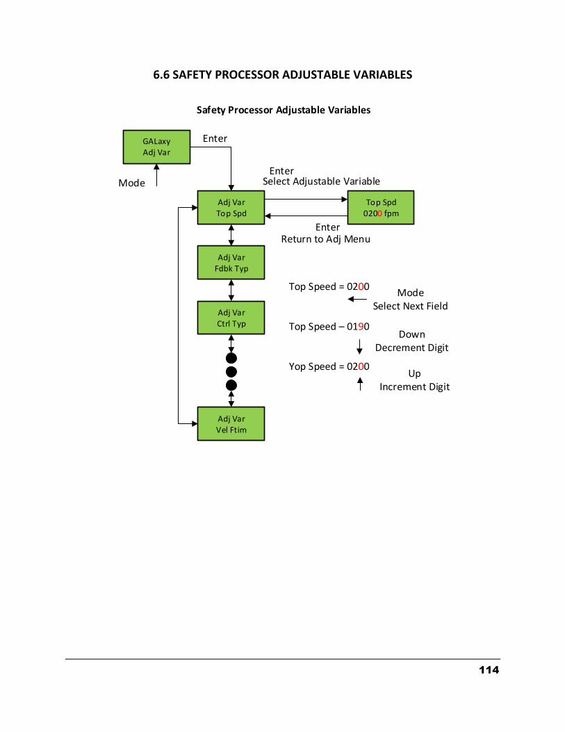
114
6.6 SAFETY PROCESSOR ADJUSTABLE VARIABLES
GALaxyAdj Var
Adj VarTop Spd
Enter
Mode
Safety Processor Adjustable Variables
Adj VarFdbk Typ
Adj VarCtrl Typ
Adj VarVel Ftim
Top Spd0200 fpm
Enter
Enter
Select Adjustable Variable
Return to Adj Menu
Top Speed = 0200
Top Speed – 0190
Yop Speed = 0200
ModeSelect Next Field
DownDecrement Digit
UpIncrement Digit
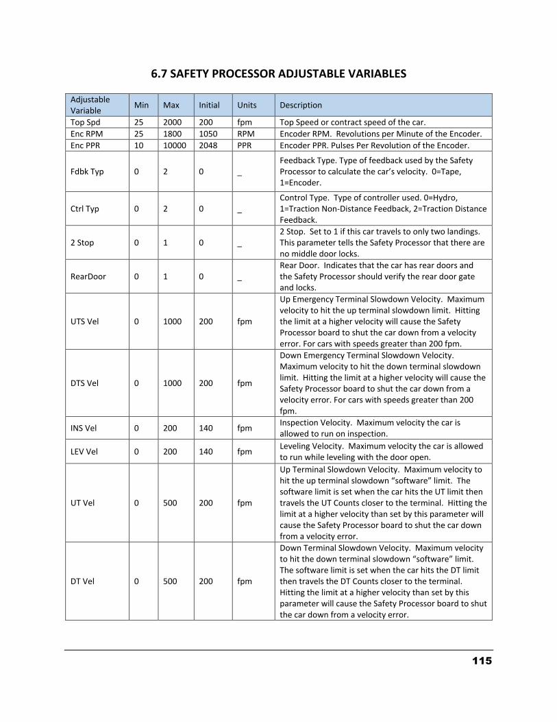
115
6.7 SAFETY PROCESSOR ADJUSTABLE VARIABLES
Adjustable Variable
Min Max Initial Units Description
Top Spd 25 2000 200 fpm Top Speed or contract speed of the car.
Enc RPM 25 1800 1050 RPM Encoder RPM. Revolutions per Minute of the Encoder.
Enc PPR 10 10000 2048 PPR Encoder PPR. Pulses Per Revolution of the Encoder.
Fdbk Typ 0 2 0 _ Feedback Type. Type of feedback used by the Safety Processor to calculate the car’s velocity. 0=Tape, 1=Encoder.
Ctrl Typ 0 2 0 _ Control Type. Type of controller used. 0=Hydro, 1=Traction Non-Distance Feedback, 2=Traction Distance Feedback.
2 Stop 0 1 0 _ 2 Stop. Set to 1 if this car travels to only two landings. This parameter tells the Safety Processor that there are no middle door locks.
RearDoor 0 1 0 _ Rear Door. Indicates that the car has rear doors and the Safety Processor should verify the rear door gate and locks.
UTS Vel 0 1000 200 fpm
Up Emergency Terminal Slowdown Velocity. Maximum velocity to hit the up terminal slowdown limit. Hitting the limit at a higher velocity will cause the Safety Processor board to shut the car down from a velocity error. For cars with speeds greater than 200 fpm.
DTS Vel 0 1000 200 fpm
Down Emergency Terminal Slowdown Velocity. Maximum velocity to hit the down terminal slowdown limit. Hitting the limit at a higher velocity will cause the Safety Processor board to shut the car down from a velocity error. For cars with speeds greater than 200 fpm.
INS Vel 0 200 140 fpm Inspection Velocity. Maximum velocity the car is allowed to run on inspection.
LEV Vel 0 200 140 fpm Leveling Velocity. Maximum velocity the car is allowed to run while leveling with the door open.
UT Vel 0 500 200 fpm
Up Terminal Slowdown Velocity. Maximum velocity to hit the up terminal slowdown “software” limit. The software limit is set when the car hits the UT limit then travels the UT Counts closer to the terminal. Hitting the limit at a higher velocity than set by this parameter will cause the Safety Processor board to shut the car down from a velocity error.
DT Vel 0 500 200 fpm
Down Terminal Slowdown Velocity. Maximum velocity to hit the down terminal slowdown “software” limit. The software limit is set when the car hits the DT limit then travels the DT Counts closer to the terminal. Hitting the limit at a higher velocity than set by this parameter will cause the Safety Processor board to shut the car down from a velocity error.

116
Adjustable Variable
Min Max Initial Units Description
UT Count 0 2000 12 Pulse Counts
Up Terminal Count. The number of counts after the UT limit is hit traveling toward the terminal landing for the UT software limit to become active. On cars with only one slowdown limit, the car would normally hit the limit at top speed during a recovery run. The UT Count allows the car time to slow down before the Safety Processor can shut the car down from a limit velocity error.
DT Count 0 2000 12 Pulse Counts
Down Terminal Count. The number of counts after the DT limit is hit traveling toward the terminal landing for the DT software limit to become active. On cars with only one slowdown limit, the car would normally hit the limit at top speed during a recovery run. The DT Count allows the car time to slow down before the Safety Processor can shut the car down from a limit velocity error.
Dmd Mult 0.5 1.5 1 _
Demand Multiplier. Multiplies the analog to digital input of the car’s demand velocity. Increase or decrease the multiplier to display the exact speed of the car on the Car Demand screen.
SoftStop 1 10 1 Sec
Soft Start Timer. During a soft stop, the speed command is brought to zero, then the brake is dropped and finally the run outputs are turned off. This timer is used to keep the run outputs from timing out during a soft stop.
Pls Ftim 0 5.00 2.00 Sec Pulse Count Fault Delay Time. Time delay to detect that the selector pulses have stopped.
Vel Ftim 0 0.500
0.180 Sec Velocity Fault Delay Time. Time delay after a velocity fault to shut the car down.
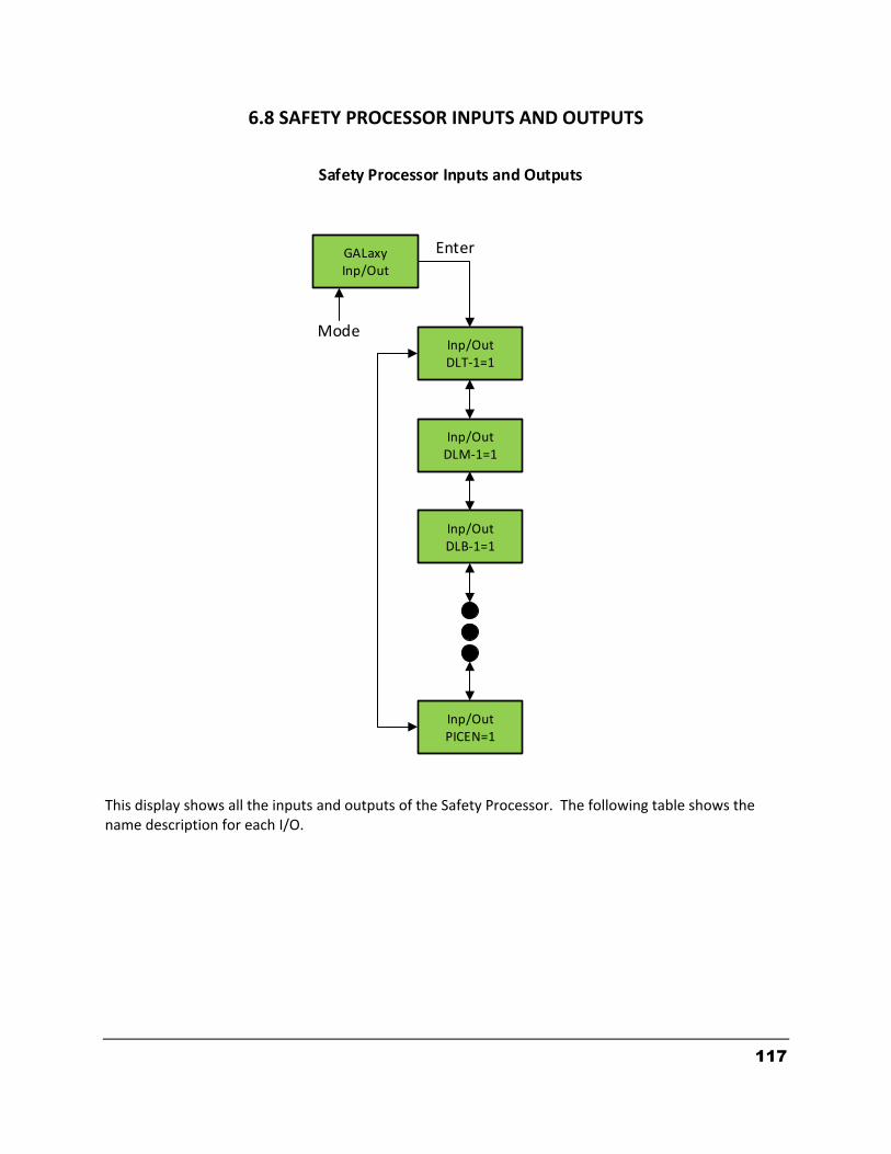
117
6.8 SAFETY PROCESSOR INPUTS AND OUTPUTS This display shows all the inputs and outputs of the Safety Processor. The following table shows the name description for each I/O.
GALaxyInp/Out
Inp/OutDLT-1=1
Inp/OutDLM-1=1
Inp/OutDLB-1=1
Inp/OutPICEN=1
Enter
Mode
Safety Processor Inputs and Outputs
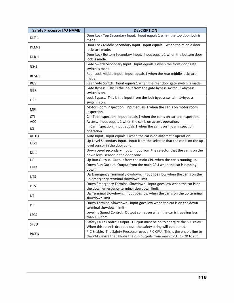
118
Safety Processor I/O NAME DESCRIPTION
DLT-1 Door Lock Top Secondary Input. Input equals 1 when the top door lock is made.
DLM-1 Door Lock Middle Secondary Input. Input equals 1 when the middle door locks are made.
DLB-1 Door Lock Bottom Secondary Input. Input equals 1 when the bottom door lock is made.
GS-1 Gate Switch Secondary Input. Input equals 1 when the front door gate switch is made.
RLM-1 Rear Lock Middle Input. Input equals 1 when the rear middle locks are made.
RGS Rear Gate Switch. Input equals 1 when the rear door gate switch is made.
GBP Gate Bypass. This is the input from the gate bypass switch. 1=bypass switch is on.
LBP Lock Bypass. This is the input from the lock bypass switch. 1=bypass switch is on.
MRI Motor Room Inspection. Input equals 1 when the car is on motor room inspection.
CTI Car Top Inspection. Input equals 1 when the car is on car top inspection.
ACC Access. Input equals 1 when the car is on access operation.
ICI In Car Inspection. Input equals 1 when the car is on in-car inspection operation.
AUTO Auto Input. Input equals 1 when the car is on automatic operation.
UL-1 Up Level Secondary Input. Input from the selector that the car is on the up level sensor in the door zone.
DL-1 Down Level Secondary Input. Input from the selector that the car is on the down level sensor in the door zone.
UP Up Run Output. Output from the main CPU when the car is running up.
DNR Down Run Output. Output from the main CPU when the car is running down.
UTS Up Emergency Terminal Slowdown. Input goes low when the car is on the up emergency terminal slowdown limit.
DTS Down Emergency Terminal Slowdown. Input goes low when the car is on the down emergency terminal slowdown limit.
UT Up Terminal Slowdown. Input goes low when the car is on the up terminal slowdown limit.
DT Down Terminal Slowdown. Input goes low when the car is on the down terminal slowdown limit.
LSCS Leveling Speed Control. Output comes on when the car is traveling less than 150 fpm.
SFCO Safety Fault Control Output. Output must be on to energize the SFC relay. When this relay is dropped out, the safety string will be opened.
PICEN PIC Enable. The Safety Processor uses a PIC CPU. This is the enable line to the PAL device that allows the run outputs from main CPU. 1=OK to run.
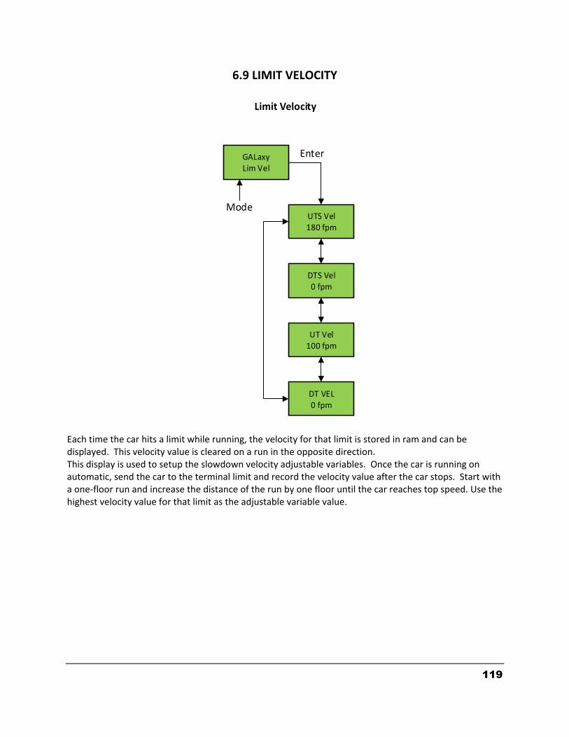
119
6.9 LIMIT VELOCITY Each time the car hits a limit while running, the velocity for that limit is stored in ram and can be displayed. This velocity value is cleared on a run in the opposite direction. This display is used to setup the slowdown velocity adjustable variables. Once the car is running on automatic, send the car to the terminal limit and record the velocity value after the car stops. Start with a one-floor run and increase the distance of the run by one floor until the car reaches top speed. Use the highest velocity value for that limit as the adjustable variable value.
GALaxyLim Vel
UTS Vel180 fpm
DTS Vel0 fpm
UT Vel100 fpm
DT VEL0 fpm
Enter
Mode
Limit Velocity
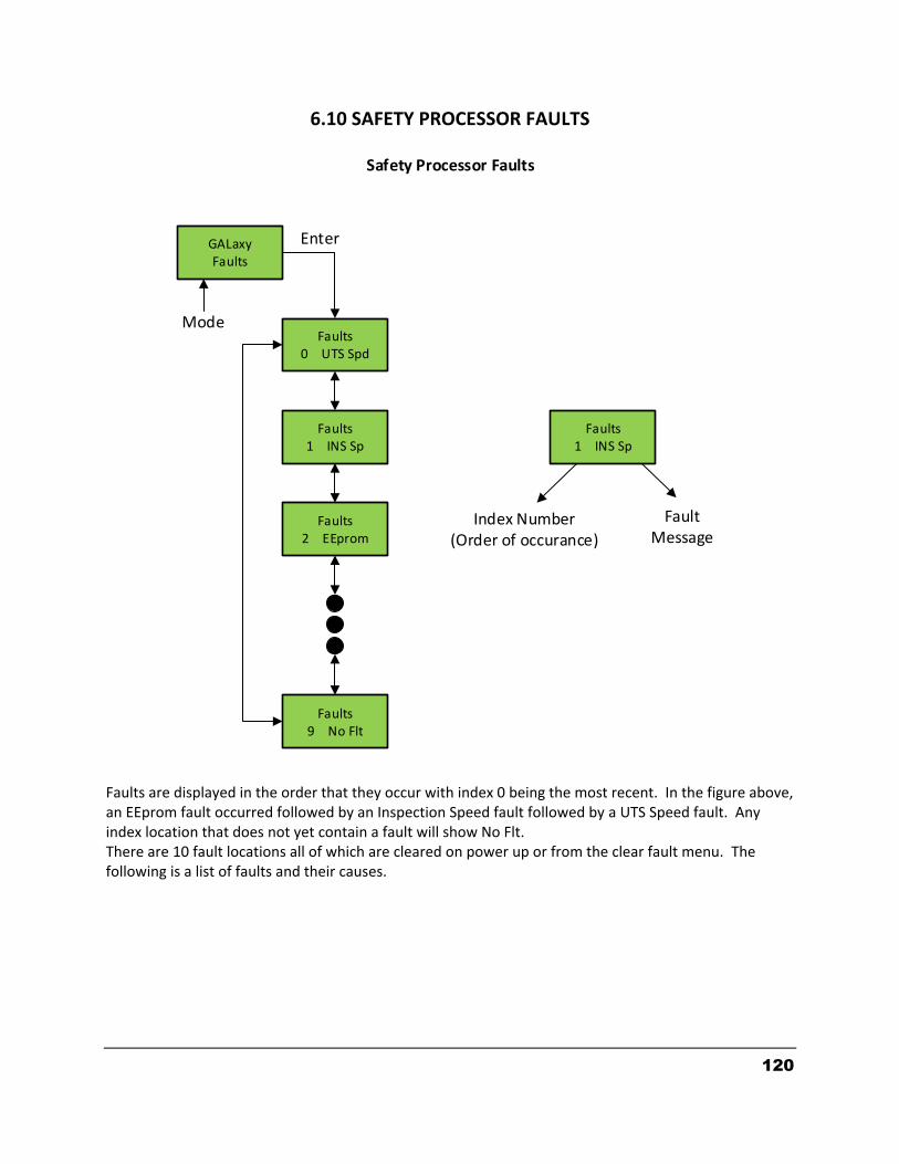
120
6.10 SAFETY PROCESSOR FAULTS Faults are displayed in the order that they occur with index 0 being the most recent. In the figure above, an EEprom fault occurred followed by an Inspection Speed fault followed by a UTS Speed fault. Any index location that does not yet contain a fault will show No Flt. There are 10 fault locations all of which are cleared on power up or from the clear fault menu. The following is a list of faults and their causes.
GALaxyFaults
Faults0 UTS Spd
Faults1 INS Sp
Faults2 EEprom
Faults9 No Flt
Enter
Mode
Safety Processor Faults
Faults1 INS Sp
Index Number(Order of occurance)
FaultMessage
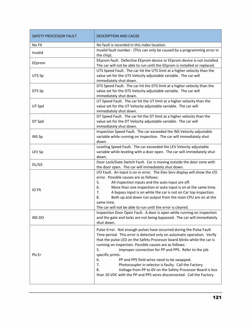
121
SAFETY PROCESSOR FAULT DESCRIPTION AND CAUSE
No Flt No fault is recorded in this index location.
Invalid Invalid fault number. (This can only be caused by a programming error in the chip).
EEprom EEprom fault. Defective EEprom device or EEprom device is not installed. The car will not be able to run until the EEprom is installed or replaced.
UTS Sp UTS Speed Fault. The car hit the UTS limit at a higher velocity than the value set for the UTS Velocity adjustable variable. The car will immediately shut down.
DTS Sp DTS Speed Fault. The car hit the DTS limit at a higher velocity than the value set for the DTS Velocity adjustable variable. The car will immediately shut down.
UT Spd UT Speed Fault. The car hit the UT limit at a higher velocity than the value set for the UT Velocity adjustable variable. The car will immediately shut down.
DT Spd DT Speed Fault. The car hit the DT limit at a higher velocity than the value set for the DT Velocity adjustable variable. The car will immediately shut down.
INS Sp Inspection Speed Fault. The car exceeded the INS Velocity adjustable variable while running on inspection. The car will immediately shut down.
LEV Sp Leveling Speed Fault. The car exceeded the LEV Velocity adjustable variable while leveling with a door open. The car will immediately shut down.
DL/GS Door Lock/Gate Switch Fault. Car is moving outside the door zone with the door open. The car will immediately shut down.
IO Flt
I/O Fault. An input is on in error. The Elev Serv display will show the I/O error. Possible causes are as follows: 5. All inspection inputs and the auto input are off. 6. More than one inspection or auto input is on at the same time. 7. A bypass input is on while the car is not on Car top inspection. 8. Both up and down run output from the main CPU are on at the same time. The car will not be able to run until the error is cleared.
INS DO Inspection Door Open Fault. A door is open while running on inspection and the gate and locks are not being bypassed. The car will immediately shut down.
Pls Er
Pulse Error. Not enough pulses have occurred during the Pulse Fault Time period. This error is detected only on automatic operation. Verify that the pulse LED on the Safety Processor board blinks while the car is running on inspection. Possible causes are as follows: 5. Improper connection for PP and PPS. Refer to the job specific prints. 6. PP and PPS field wires need to be swapped. 7. Photocoupler in selector is faulty. Call the Factory. 8. Voltage from PP to 0V on the Safety Processor Board is less than 10 VDC with the PP and PPS wires disconnected. Call the Factory.

122
6.11 CLEAR FAULTS
6.12 RESET SAFETY PROCESSOR FAULT LATCH
GALaxyClr Flts
Clr FltsHit Enter
Enter
Mode
Clear Faults
Enter
Faults ClearedMode
GALaxyReset
ResetHit Enter
Enter
Mode
Reset Fault Latch
Enter
Reset Fault Latch
Mode

123
6.13 SAFETY PROCESSOR BOARD TEMPERATURE
6.14 SAFETY PROCESSOR EXTERNAL TEMPERATURE
GALaxyBrd Temp
Brd Temp70 F
Enter
Mode
Board Temperature
Enter
Brd Temp21 C
Temperature of Board
Change from Fahrenheit to Centigrade
GALaxyExt Temp
Ext Temp70 F
Enter
Mode
External Temperature
Enter
Ext Temp21 C
External Sensor Temperature
Change from Fahrenheit to Centigrade
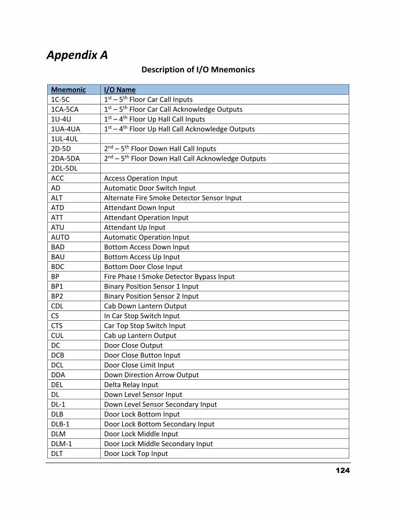
124
Appendix A Description of I/O Mnemonics
Mnemonic I/O Name
1C-5C 1st – 5th Floor Car Call Inputs
1CA-5CA 1st – 5th Floor Car Call Acknowledge Outputs
1U-4U 1st – 4th Floor Up Hall Call Inputs
1UA-4UA 1st – 4th Floor Up Hall Call Acknowledge Outputs
1UL-4UL
2D-5D 2nd – 5th Floor Down Hall Call Inputs
2DA-5DA 2nd – 5th Floor Down Hall Call Acknowledge Outputs
2DL-5DL
ACC Access Operation Input
AD Automatic Door Switch Input
ALT Alternate Fire Smoke Detector Sensor Input
ATD Attendant Down Input
ATT Attendant Operation Input
ATU Attendant Up Input
AUTO Automatic Operation Input
BAD Bottom Access Down Input
BAU Bottom Access Up Input
BDC Bottom Door Close Input
BP Fire Phase I Smoke Detector Bypass Input
BP1 Binary Position Sensor 1 Input
BP2 Binary Position Sensor 2 Input
CDL Cab Down Lantern Output
CS In Car Stop Switch Input
CTS Car Top Stop Switch Input
CUL Cab up Lantern Output
DC Door Close Output
DCB Door Close Button Input
DCL Door Close Limit Input
DDA Down Direction Arrow Output
DEL Delta Relay Input
DL Down Level Sensor Input
DL-1 Down Level Sensor Secondary Input
DLB Door Lock Bottom Input
DLB-1 Door Lock Bottom Secondary Input
DLM Door Lock Middle Input
DLM-1 Door Lock Middle Secondary Input
DLT Door Lock Top Input
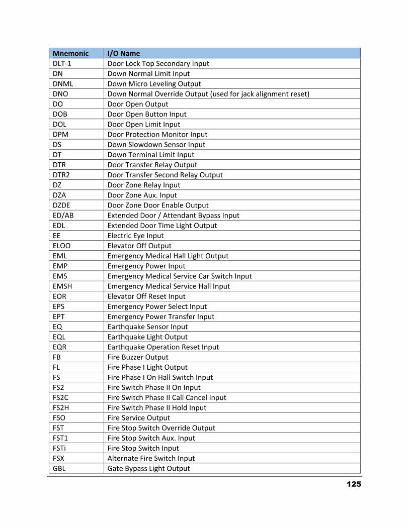
125
Mnemonic I/O Name
DLT-1 Door Lock Top Secondary Input
DN Down Normal Limit Input
DNML Down Micro Leveling Output
DNO Down Normal Override Output (used for jack alignment reset)
DO Door Open Output
DOB Door Open Button Input
DOL Door Open Limit Input
DPM Door Protection Monitor Input
DS Down Slowdown Sensor Input
DT Down Terminal Limit Input
DTR Door Transfer Relay Output
DTR2 Door Transfer Second Relay Output
DZ Door Zone Relay Input
DZA Door Zone Aux. Input
DZDE Door Zone Door Enable Output
ED/AB Extended Door / Attendant Bypass Input
EDL Extended Door Time Light Output
EE Electric Eye Input
ELOO Elevator Off Output
EML Emergency Medical Hall Light Output
EMP Emergency Power Input
EMS Emergency Medical Service Car Switch Input
EMSH Emergency Medical Service Hall Input
EOR Elevator Off Reset Input
EPS Emergency Power Select Input
EPT Emergency Power Transfer Input
EQ Earthquake Sensor Input
EQL Earthquake Light Output
EQR Earthquake Operation Reset Input
FB Fire Buzzer Output
FL Fire Phase I Light Output
FS Fire Phase I On Hall Switch Input
FS2 Fire Switch Phase II On Input
FS2C Fire Switch Phase II Call Cancel Input
FS2H Fire Switch Phase II Hold Input
FSO Fire Service Output
FST Fire Stop Switch Override Output
FST1 Fire Stop Switch Aux. Input
FSTi Fire Stop Switch Input
FSX Alternate Fire Switch Input
GBL Gate Bypass Light Output

126
Mnemonic I/O Name
GBP Gate Switch Bypass Input
GS Car Gate Switch Input
GS-1 Gate Switch Secondary Input
HB Handicap Buzzer Output
HBE Handicap Buzzer Enable Output
HC Hall Call Common Input
HEOF Hall Switch Elevator Off Input
HWS Hoistway Smoke Sensor Input
HWS2 Hoistway Smoke Second Sensor Input
ICI In-Car Inspection Input
ID Car top Inspection Down Input
IND Independent Input
INS Car Top Inspection Input
ISER In Service Output
IU Car Top Inspection Up Input
LBL Door Lock Bypass Light Output
LBP Lock Bypass Input
LC Logic Common Input
LD Down Hall Lantern Output
LOS Low Oil Switch Input
LPS Low Pressure Switch Input
LU Up Hall Lantern Output
MCA Motor Contactor Output
MCAi Motor Contactor Input
MCC Motor Contactor Output
MCCi Motor Contactor Input
MDC Middle Door Close Input
MES Main Egress Smoke Detector Sensor Input
MRI Motor Room Inspection Input
MRID Motor Room Inspection Down Input
MRIE Motor Room Inspection Enable Input
MRIU Motor Room Inspection Up Input
MRS Motor Room Smoke Sensor Input
MST Motor Start Output
NUD Door Nudging Output
P Potential (Run Contactor) Input
P1-P5 1st – 5th Discrete Floor Position Indicator Outputs
PFC Primary Fault Control Output
PKE Parking Enable Input
RCM Retiring Cam Output
RTL Return to Lobby Input
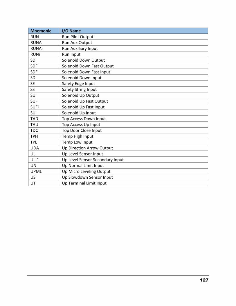
127
Mnemonic I/O Name
RUN Run Pilot Output
RUNA Run Aux Output
RUNAi Run Auxiliary Input
RUNi Run Input
SD Solenoid Down Output
SDF Solenoid Down Fast Output
SDFi Solenoid Down Fast Input
SDi Solenoid Down Input
SE Safety Edge Input
SS Safety String Input
SU Solenoid Up Output
SUF Solenoid Up Fast Output
SUFi Solenoid Up Fast Input
SUi Solenoid Up Input
TAD Top Access Down Input
TAU Top Access Up Input
TDC Top Door Close Input
TPH Temp High Input
TPL Temp Low Input
UDA Up Direction Arrow Output
UL Up Level Sensor Input
UL-1 Up Level Sensor Secondary Input
UN Up Normal Limit Input
UPML Up Micro Leveling Output
US Up Slowdown Sensor Input
UT Up Terminal Limit Input