Simon Fairfield Library Renovation - Douglas · Steel W Shapes and Tees: ASTM A992/A992M. Rolled...
45
Section 00 01 01 COVER PAGE OUTLINE SPECIFICATIONS FOR Simon Fairfield Library Renovation AT THE Simon Fairfield Library 290 Main Street Douglas , MA 01516 November 16, 2011 Prepared by: DURLAND - VAN VOORHIS Architects 628 Pleasant Street - Suite 322 New Bedford, Massachusetts 02740
Transcript of Simon Fairfield Library Renovation - Douglas · Steel W Shapes and Tees: ASTM A992/A992M. Rolled...

Section 00 01 01COVER PAGE
OUTLINE SPECIFICATIONS
FOR
Simon Fairfield LibraryRenovation
AT THE
Simon Fairfield Library290 Main StreetDouglas , MA
01516
November 16, 2011
Prepared by:
DURLAND - VAN VOORHIS Architects 628 Pleasant Street - Suite 322 New Bedford, Massachusetts
02740
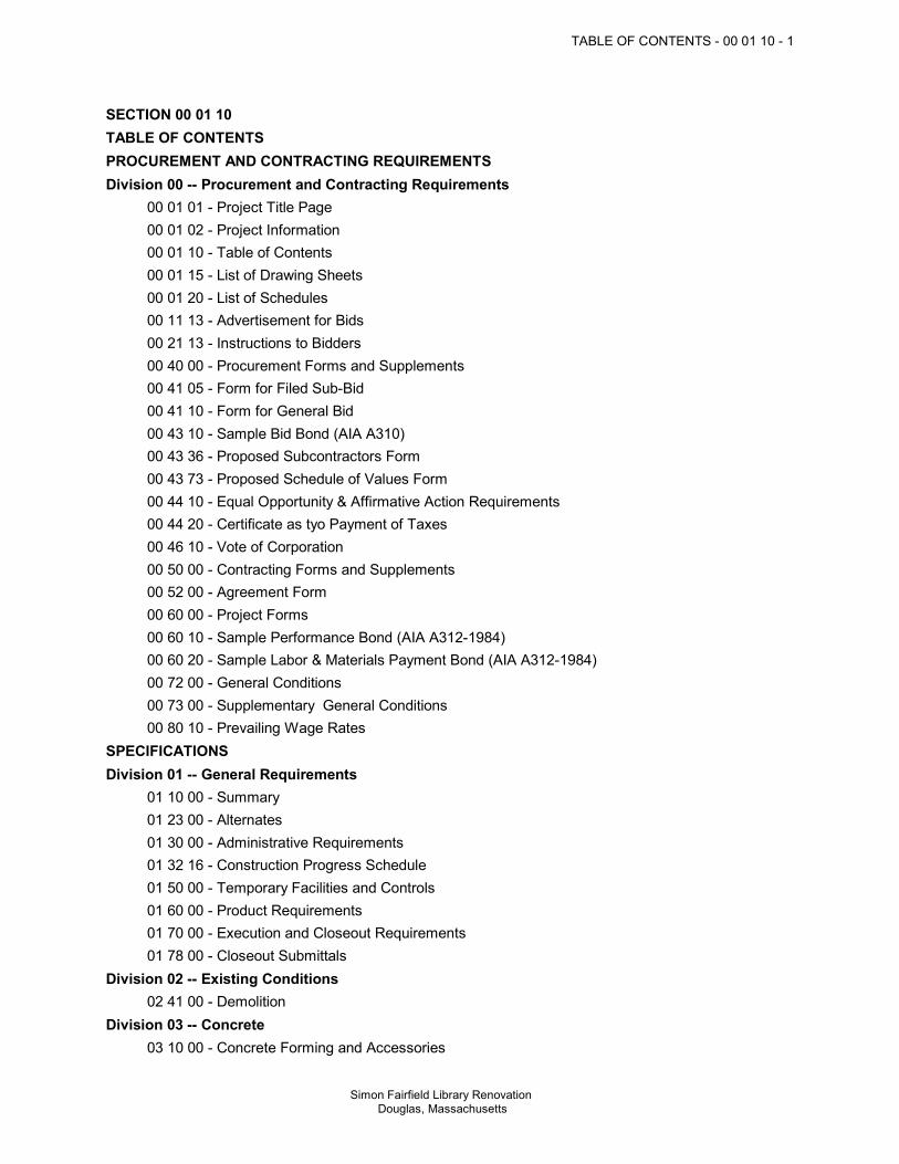
TABLE OF CONTENTS - 00 01 10 - 1
Simon Fairfield Library Renovation Douglas, Massachusetts
SECTION 00 01 10TABLE OF CONTENTSPROCUREMENT AND CONTRACTING REQUIREMENTSDivision 00 -- Procurement and Contracting Requirements
00 01 01 - Project Title Page00 01 02 - Project Information00 01 10 - Table of Contents00 01 15 - List of Drawing Sheets00 01 20 - List of Schedules00 11 13 - Advertisement for Bids00 21 13 - Instructions to Bidders00 40 00 - Procurement Forms and Supplements00 41 05 - Form for Filed Sub-Bid00 41 10 - Form for General Bid00 43 10 - Sample Bid Bond (AIA A310)00 43 36 - Proposed Subcontractors Form00 43 73 - Proposed Schedule of Values Form00 44 10 - Equal Opportunity & Affirmative Action Requirements00 44 20 - Certificate as tyo Payment of Taxes00 46 10 - Vote of Corporation00 50 00 - Contracting Forms and Supplements00 52 00 - Agreement Form00 60 00 - Project Forms00 60 10 - Sample Performance Bond (AIA A312-1984)00 60 20 - Sample Labor & Materials Payment Bond (AIA A312-1984)00 72 00 - General Conditions00 73 00 - Supplementary General Conditions00 80 10 - Prevailing Wage Rates
SPECIFICATIONSDivision 01 -- General Requirements
01 10 00 - Summary01 23 00 - Alternates01 30 00 - Administrative Requirements01 32 16 - Construction Progress Schedule01 50 00 - Temporary Facilities and Controls01 60 00 - Product Requirements01 70 00 - Execution and Closeout Requirements01 78 00 - Closeout Submittals
Division 02 -- Existing Conditions 02 41 00 - Demolition
Division 03 -- Concrete 03 10 00 - Concrete Forming and Accessories

2 - TABLE OF CONTENTS - 00 01 10
Simon Fairfield Library Renovation Douglas, Massachusetts
03 20 00 - Concrete Reinforcing03 30 00 - Cast-in-Place Concrete
Division 04 -- Masonry 04 20 00 - Unit Masonry
Division 05 -- Metals 05 12 00 - Structural Steel Framing05 31 00 - Steel Decking05 50 00 - Metal Fabrications05 51 00 - Metal Stairs
Division 06 -- Wood, Plastics, and Composites 06 10 00 - Rough Carpentry06 20 00 - Finish Carpentry06 41 00 - Architectural Wood Casework
Division 07 -- Thermal and Moisture Protection 07 21 00 - Thermal Insulation07 21 19 - Foamed-In-Place Insulation07 51 00 - Built-Up Bituminous Roofing07 62 00 - Sheet Metal Flashing and Trim07 90 05 - Joint Sealers
Division 08 -- Openings 08 11 13 - Hollow Metal Doors and Frames08 14 33 - Stile and Rail Wood Doors08 43 13 - Aluminum-Framed Storefronts08 51 13 - Aluminum Windows08 71 00 - Door Hardware08 80 00 - Glazing08 83 00 - Mirrors08 91 00 - Louvers
Division 09 -- Finishes 09 22 16 - Non-Structural Metal Framing09 26 13 - Gypsum Veneer Plastering09 30 00 - Tiling09 51 00 - Acoustical Ceilings09 64 29 - Wood Strip and Plank Flooring09 65 00 - Resilient Flooring09 67 14 - Resilient Urethane Flooring09 68 00 - Carpeting09 90 00 - Painting and Coating09 91 00 - Painting
Division 10 -- Specialties 10 11 01 - Visual Display Boards
TABLE OF CONTENTS - 00 01 10 - 3
Simon Fairfield Library Renovation Douglas, Massachusetts
10 14 00 - Signage10 28 00 - Toilet, Bath, and Laundry Accessories10 44 00 - Fire Protection Specialties
Division 11 -- Equipment Division 12 -- Furnishings Division 13 -- Special Construction Division 14 -- Conveying Equipment
14 20 10 - Passenger ElevatorsDivision 21 -- Fire Suppression Division 22 -- Plumbing Division 23 -- Heating, Ventilating, and Air-Conditioning (HVAC) Division 26 -- Electrical Division 27 -- Communications Division 28 -- Electronic Safety and Security
28 31 00 - Fire Detection and AlarmDivision 31 -- Earthwork
31 22 00 - Grading31 23 16 - Excavation31 23 16.13 - Trenching31 23 23 - Fill
Division 32 -- Exterior Improvements 32 12 16 - Asphalt Paving32 13 13 - Concrete Paving32 17 13 - Parking Bumpers32 17 23.13 - Painted Pavement Markings32 92 23 - Sodding32 93 00 - Plants
Division 33 -- Utilities 33 05 13 - Manholes and Structures33 31 11 - Site Sanitary Utility Sewerage Piping33 41 11 - Site Storm Utility Drainage Piping33 49 24 - Underground Storm Water Retention Chamber
END OF TABLE OF CONTENTS
GENERAL REQUIREMENTS - 01 - 1
Simon Fairfield Library Renovation Douglas, Massachusetts
DIVISION 01 - GENERAL REQUIREMENTSSECTION 01 30 00 - ADMINISTRATIVE REQUIREMENTS
SUBMITTALS FOR REVIEW Submit to Architect for review for the limited purpose of checking for conformance with
information given and the design concept expressed in the contract documents. Samples will be reviewed only for aesthetic, color, or finish selection. After review, provide copies and distribute in accordance with SUBMITTAL PROCEDURES
article below and for record documents purposes described in Section 01 78 00 - CLOSEOUTSUBMITTALS.
SUBMITTALS FOR PROJECT CLOSEOUT Submit for Owner's benefit during and after project completion.NUMBER OF COPIES OF SUBMITTALS Documents for Review:
Small Size Sheets, Not Larger Than 8-1/2 x 11 inches: Submit the number of copies thatContractor requires, plus two copies that will be retained by Architect.
Samples: Submit the number specified in individual specification sections; one of which will beretained by Architect. After review, produce duplicates. Retained samples will not be returned to Contractor unless specifically so stated.
SUBMITTAL PROCEDURES Sequentially number the transmittal form. Revise submittals with original number and a
sequential alphabetic suffix. Identify Project, Contractor, Subcontractor or supplier; pertinent drawing and detail number, and
specification section number, as appropriate on each copy. Apply Contractor's stamp, signed or initialed certifying that review, approval, verification of
Products required, field dimensions, adjacent construction Work, and coordination ofinformation is in accordance with the requirements of the Work and Contract Documents.
Provide space for Contractor and Architect review stamps. When revised for resubmission, identify all changes made since previous submission. Distribute reviewed submittals as appropriate. Instruct parties to promptly report any inability to
comply with requirements.SECTION 01 60 00 - PRODUCT REQUIREMENTS
NEW PRODUCTS Provide new products unless specifically required or permitted by the Contract Documents.PRODUCT OPTIONS Products Specified by Reference Standards or by Description Only: Use any product meeting
those standards or description. Products Specified by Naming One or More Manufacturers: Use a product of one of the
manufacturers named and meeting specifications, no options or substitutions allowed. Products Specified by Naming One or More Manufacturers with a Provision for Substitutions:
Submit a request for substitution for any manufacturer not named.SECTION 01 78 00 - CLOSEOUT SUBMITTALS
WARRANTIES AND BONDS Obtain warranties and bonds, executed in duplicate by responsible Subcontractors, suppliers,
and manufacturers, within 10 days after completion of the applicable item of work. Except for

2 - GENERAL REQUIREMENTS - 01
Simon Fairfield Library Renovation Douglas, Massachusetts
items put into use with Owner's permission, leave date of beginning of time of warranty until the Dateof Substantial completion is determined.
EXISTING CONDITIONS - 02 - 1
Simon Fairfield Library Renovation Douglas, Massachusetts
DIVISION 02 - EXISTING CONDITIONSSECTION 02 41 00 - DEMOLITION
GENERAL PROCEDURES AND PROJECT CONDITIONS Comply with applicable codes and regulations for demolition operations and safety of adjacent
structures and the public.

CONCRETE - 03 - 1
Simon Fairfield Library Renovation Douglas, Massachusetts
DIVISION 03 - CONCRETESECTION 03 10 00 - CONCRETE FORMING AND ACCESSORIES
FORMWORK - GENERAL Provide concrete forms, accessories, shoring, and bracing as required to accomplish
cast-in-place concrete work. Design and construct to provide resultant concrete that conforms to design with respect to
shape, lines, and dimensions. Comply with applicable state and local codes with respect to design, fabrication, erection, and
removal of formwork.WOOD FORM MATERIALS Plywood: Douglas Fir species; solid one side grade; sound undamaged sheets with clean, true
edges.PREFABRICATED FORMS Preformed Steel Forms: Minimum 16 gage matched, tight fitting, stiffened to support weight of
concrete without deflection detrimental to tolerances and appearance of finished surfaces.SECTION 03 20 00 - CONCRETE REINFORCING
REINFORCEMENT Reinforcing Steel: ASTM A615/A615M Grade 40 (280). Reinforcing Steel: ASTM A706/A706M, deformed low-alloy steel bars. Stirrup Steel: ASTM A82/A82M steel wire, epoxy coated in accordance with ASTM
A775/A775M. Steel Welded Wire Reinforcement: ASTM A884/A884M, deformed, Class A epoxy coated type.
SECTION 03 30 00 - CAST-IN-PLACE CONCRETEFORMWORK Comply with requirements of Section 03 10 00.REINFORCEMENT Comply with requirements of Section 03 20 00.CONCRETE MATERIALS Cement: ASTM C150, Type I - Normal Portland type. Fine and Coarse Aggregates: ASTM C33. Water: Clean and not detrimental to concrete.ACCESSORY MATERIALS Underslab Vapor Retarder: Multi-layer, fabric-, cord-, grid-, or aluminum-reinforced
polyethylene or equivalent, complying with ASTM E1745, Class A; stated by manufacturer assuitable for installation in contact with soil or granular fill under concrete slabs. Single plypolyethylene is prohibited.
Non-Shrink Cementitious Grout: ASTM C1107/C1107M; premixed compound consisting ofnon-metallic aggregate, cement, water reducing and plasticizing agents.
CONCRETE MIX DESIGN Proportioning Normal Weight Concrete: Comply with ACI 211.1 recommendations. Concrete Strength: Establish required average strength for each type of concrete on the basis
of field experience or trial mixtures, as specified in ACI 301. Normal Weight Concrete:
Compressive Strength, when tested in accordance with ASTM C39/C39M at 28 days:4,000 psi.

MASONRY - 04 - 1
Simon Fairfield Library Renovation Douglas, Massachusetts
DIVISION 04 - MASONRYSECTION 04 20 00 - UNIT MASONRY
CONCRETE MASONRY UNITS Concrete Block: Comply with referenced standards and as follows:
Size: Standard units with nominal face dimensions of 16 x 8 inches and nominal depth of8 inches.
Load-Bearing Units: ASTM C90, normal weight. Concrete Brick:
For architectural and paver use, ASTM C1634 (or ASTM C55-03 Grade N), non-cored(solid), normal weight.
BRICK UNITS Facing Brick: ASTM C216, Type FBS, Grade SW. Building (Common) Brick: ASTM C62, Grade SW; solid units.MORTAR AND GROUT MATERIALS Masonry Cement: ASTM C91, Type N. Portland Cement: ASTM C150, Type I; color as required to produce approved color sample. Hydrated Lime: ASTM C207, Type S. Mortar Aggregate: ASTM C144. Grout Aggregate: ASTM C404.REINFORCEMENT AND ANCHORAGE Reinforcing Steel: Type specified in Section 03 20 00; size as indicated on drawings; epoxy
finish. Multiple Wythe Joint Reinforcement: Truss type; fabricated with moisture drip; ASTM
A82/A82M steel wire, hot dip galvanized after fabrication to ASTM A153/153M, Class B; 0.1483inch side rods with 0.1483 inch cross rods; width as required to provide not more than 1 inchand not less than 1/2 inch of mortar coverage on each exposure.
Two-Piece Wall Ties: Formed steel wire, 0.1875 inch thick, adjustable, eye and pintle type, hotdip galvanized to ASTM A153/A153M, Class B, sized to provide not more than 1 inch and notless than 1/2 inch of mortar coverage from masonry face and to allow vertical adjustment of upto 1-1/4 in.
Masonry Veneer Anchors: 2-piece anchors that permit differential movement between masonryveneer and structural backup, hot dip galvanized to ASTM A153/A153M, Class B.
FLASHINGS Metal Flashing Materials: Copper, as specified in Section 07 62 00.ACCESSORIES Preformed Control Joints: Rubber material. Provide with corner and tee accessories, fused
joints. Cavity Mortar Control: Semi-rigid polyethylene or polyester mesh panels, sized to thickness of
wall cavity, and designed to prevent mortar droppings from clogging weeps and cavity vents andallow proper cavity drainage.
Weeps: Polyethylene tubing. Cavity Vents: Polyester mesh.MORTAR AND GROUT MIXES Mortar for Unit Masonry: ASTM C270, using the Proportion Specification.

METALS - 05 - 1
Simon Fairfield Library Renovation Douglas, Massachusetts
DIVISION 05 - METALSSECTION 05 12 00 - STRUCTURAL STEEL FRAMING
MATERIALS Steel Angles and Plates: ASTM A36/A36M. Steel W Shapes and Tees: ASTM A992/A992M. Rolled Steel Structural Shapes: ASTM A992/A992M. Steel Shapes, Plates, and Bars: ASTM A242/A242M high-strength, corrosion-resistant
structural steel. Cold-Formed Structural Tubing: ASTM A500, Grade B. Steel Plate: ASTM A514/A514M. Load Indicator Washers: Provide washers complying with ASTM F959 at all connections
requiring high-strength bolts. Welding Materials: AWS D1.1; type required for materials being welded. Grout: Non-shrink, non-metallic aggregate type, complying with ASTM C1107/C1107M and
capable of developing a minimum compressive strength of 7,000 psi at 28 days. Provide________ manufactured by ________.
Shop and Touch-Up Primer: Fabricator's standard, complying with VOC limitations ofauthorities having jurisdiction.
SECTION 05 31 00 - STEEL DECKINGSTEEL DECK All Deck Types: Select and design metal deck in accordance with SDI Design Manual. Roof Deck: Non-composite type, fluted steel sheet:
Galvanized Steel Sheet: ASTM A653/A653M, Structural Steel (SS) Grade 33/230, withG90/Z275 galvanized coating.
Composite Floor Deck: Fluted steel sheet embossed to interlock with concrete: Galvanized Steel Sheet: ASTM A653/A653M, Structural Steel (SS) Grade 33/230, with
G90/Z275 galvanized coating. Primer: Shop coat of manufacturer's standard primer paint over cleaned and
phosphatized substrate.SECTION 05 50 00 - METAL FABRICATIONS
MATERIALS - STEEL Steel Sections: ASTM A36/A36M. Steel Tubing: ASTM A500, Grade B cold-formed structural tubing. Plates: ASTM A283. Pipe: ASTM A53/A53M, Grade B Schedule 40, black finish. Bolts, Nuts, and Washers: ASTM A325 (ASTM A325M), Type 1 , galvanized to ASTM
A153/A153M where connecting galvanized components. Welding Materials: AWS D1.1/D1.1M; type required for materials being welded. Shop and Touch-Up Primer: SSPC-Paint 15, complying with VOC limitations of authorities
having jurisdiction. Touch-Up Primer for Galvanized Surfaces: SSPC-Paint 20, Type I - Inorganic, complying with
VOC limitations of authorities having jurisdiction.MATERIALS - ALUMINUM Extruded Aluminum: ASTM B221 (ASTM B221M), 6063 alloy, T6 temper. Sheet Aluminum: ASTM B209 (ASTM B209M), 5052 alloy, H32 or H22 temper.

2 - METALS - 05
Simon Fairfield Library Renovation Douglas, Massachusetts
Aluminum-Alloy Drawn Seamless Tubes: ASTM B210 (ASTM B210M), 6063 alloy , T6 temper. Bolts, Nuts, and Washers: Stainless steel. Welding Materials: AWS D1.2/D1.2M; type required for materials being welded.FABRICATION Fit and shop assemble items in largest practical sections, for delivery to site. Fabricate items with joints tightly fitted and secured.FINISHES - STEEL Prime paint all steel items.FINISHES - ALUMINUM Exterior Aluminum Surfaces: Class I color anodized. Interior Aluminum Surfaces: Class I natural anodized.
SECTION 05 51 00 - METAL STAIRSMETAL STAIRS - GENERAL Metal Stairs: Provide stairs of the design specified, complete with landing platforms, vertical
and horizontal supports, railings, and guards, fabricated accurately for anchorage to each otherand to building structure.
Fasteners: Same material or compatible with materials being fastened; type consistent withdesign and specified quality level.
MATERIALS Steel Sections: ASTM A36/A36M. Steel Tubing: ASTM A500 or ASTM A501 structural tubing, round and shapes as indicated. Steel Plates: ASTM A6/A6M or ASTM A283/A283M. Pipe: ASTM A53/A53M, Grade B Schedule 40, black finish. Ungalvanized Steel Sheet: Hot- or cold-rolled, except use cold-rolled where finished work will
be exposed to view. Galvanized Steel Sheet: ASTM A653/A653M, Structural Steel (SS) Grade 33/230 with
G40/Z120 coating. Gratings: Bar gratings complying with NAAMM MBG 531 or NAAMM MBG 532, whichever
applies based on bar sizes. Concrete Fill: Type specified in Section 03300. Concrete Reinforcement: Mesh type as detailed, galvanized. Glazing: Tempered float glass; clear. Steel Bolts, Nuts, and Washers: , galvanized to ASTM A153/A153M where connecting
galvanized components. Welding Materials: AWS D1.1; type required for materials being welded.SHOP FINISHING Clean surfaces of rust, scale, grease, and foreign matter prior to finishing. Prime Painting: Use specified shop- and touch-up primer. Galvanizing: Hot-dip galvanize to minimum requirements of ASTM A123/A123M.
WOOD, PLASTICS, AND COMPOSITES - 06 - 1
Simon Fairfield Library Renovation Douglas, Massachusetts
DIVISION 06 - WOOD, PLASTICS, AND COMPOSITESSECTION 06 10 00 - ROUGH CARPENTRY
GENERAL REQUIREMENTS Dimension Lumber: Comply with PS 20 and requirements of specified grading agencies.
If no species is specified, provide any species graded by the agency specified; if nograding agency is specified, provide lumber graded by any grading agency meeting thespecified requirements.
Grading Agency: Any grading agency whose rules are approved by the Board of Review,American Lumber Standard Committee (www.alsc.org) and who provides grading servicefor the species and grade specified; provide lumber stamped with grade mark unlessotherwise indicated.
DIMENSION LUMBER FOR CONCEALED APPLICATIONS Sizes: Nominal sizes as indicated on drawings, S4S. Moisture Content: S-dry or MC19.CONSTRUCTION PANELS Subfloor/Underlayment Combination: APA PRP-108, Rated Sturd-I-Floor.
Exposure Class: Exterior. Span Rating: 16 inches. Thickness: 3/4 inches, nominal. Edges: Tongue and groove.
Underlayment: APA Underlayment; plywood, Exposure 2, 1/2 inch thick. Fully sanded faces atresilient flooring.
Communications and Electrical Room Mounting Boards: PS 1 A-D plywood, or medium densityfiberboard; 3/4 inch thick; flame spread index of 25 or less, smoke developed index of 450 orless, when tested in accordance with ASTM E84.
FACTORY WOOD TREATMENT Treated Lumber and Plywood: Comply with requirements of AWPA U1 - Use Category System
for wood treatments determined by use categories, expected service conditions, and specificapplications.
SECTION 06 20 00 - FINISH CARPENTRYFINISH CARPENTRY ITEMS Quality Grade: Unless otherwise indicated provide products of quality specified by
AWI//AWMAC/WI Architectural Woodwork Standards for Premium Grade.LUMBER MATERIALSSHEET MATERIALSPLASTIC LAMINATE MATERIALSFABRICATION Shop assemble work for delivery to site, permitting passage through building openings.
SECTION 06 41 00 - ARCHITECTURAL WOOD CASEWORKCABINETS Quality Grade: Unless otherwise indicated provide products of quality specified by
AWI//AWMAC/WI Architectural Woodwork Standards for Premium Grade.LAMINATE MATERIALSCOUNTERTOPSSHOP FINISHING

2 - WOOD, PLASTICS, AND COMPOSITES - 06
Simon Fairfield Library Renovation Douglas, Massachusetts
Finish work in accordance with AWI/AWMAC/WI Architectural Woodwork Standards, Section 5- Finishing for Grade specified and as follows:
THERMAL AND MOISTURE PROTECTION - 07 - 1
Simon Fairfield Library Renovation Douglas, Massachusetts
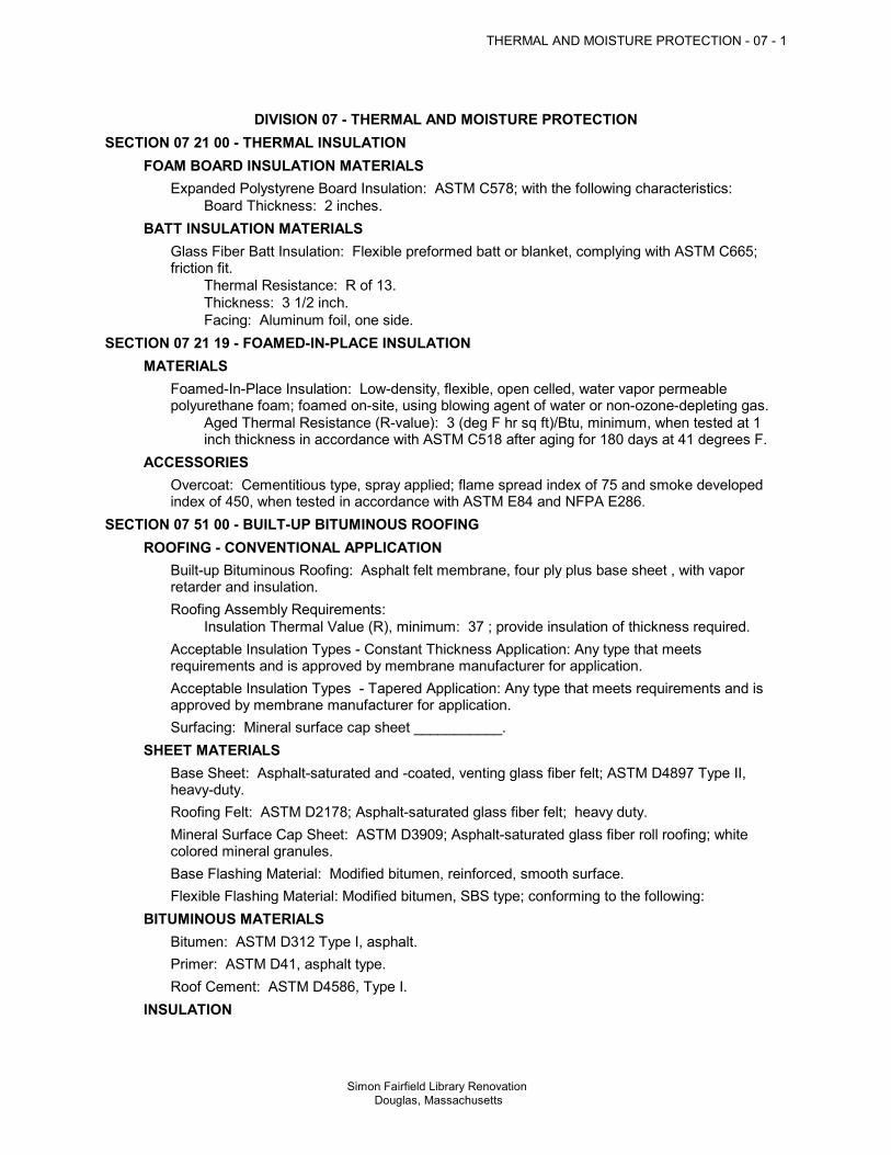
DIVISION 07 - THERMAL AND MOISTURE PROTECTIONSECTION 07 21 00 - THERMAL INSULATION
FOAM BOARD INSULATION MATERIALS Expanded Polystyrene Board Insulation: ASTM C578; with the following characteristics:
Board Thickness: 2 inches.BATT INSULATION MATERIALS Glass Fiber Batt Insulation: Flexible preformed batt or blanket, complying with ASTM C665;
friction fit. Thermal Resistance: R of 13. Thickness: 3 1/2 inch. Facing: Aluminum foil, one side.
SECTION 07 21 19 - FOAMED-IN-PLACE INSULATIONMATERIALS Foamed-In-Place Insulation: Low-density, flexible, open celled, water vapor permeable
polyurethane foam; foamed on-site, using blowing agent of water or non-ozone-depleting gas. Aged Thermal Resistance (R-value): 3 (deg F hr sq ft)/Btu, minimum, when tested at 1
inch thickness in accordance with ASTM C518 after aging for 180 days at 41 degrees F.ACCESSORIES Overcoat: Cementitious type, spray applied; flame spread index of 75 and smoke developed
index of 450, when tested in accordance with ASTM E84 and NFPA E286.SECTION 07 51 00 - BUILT-UP BITUMINOUS ROOFING
ROOFING - CONVENTIONAL APPLICATION Built-up Bituminous Roofing: Asphalt felt membrane, four ply plus base sheet , with vapor
retarder and insulation. Roofing Assembly Requirements:
Insulation Thermal Value (R), minimum: 37 ; provide insulation of thickness required. Acceptable Insulation Types - Constant Thickness Application: Any type that meets
requirements and is approved by membrane manufacturer for application. Acceptable Insulation Types - Tapered Application: Any type that meets requirements and is
approved by membrane manufacturer for application. Surfacing: Mineral surface cap sheet ___________.SHEET MATERIALS Base Sheet: Asphalt-saturated and -coated, venting glass fiber felt; ASTM D4897 Type II,
heavy-duty. Roofing Felt: ASTM D2178; Asphalt-saturated glass fiber felt; heavy duty. Mineral Surface Cap Sheet: ASTM D3909; Asphalt-saturated glass fiber roll roofing; white
colored mineral granules. Base Flashing Material: Modified bitumen, reinforced, smooth surface. Flexible Flashing Material: Modified bitumen, SBS type; conforming to the following:BITUMINOUS MATERIALS Bitumen: ASTM D312 Type I, asphalt. Primer: ASTM D41, asphalt type. Roof Cement: ASTM D4586, Type I.INSULATION

2 - THERMAL AND MOISTURE PROTECTION - 07
Simon Fairfield Library Renovation Douglas, Massachusetts
Cellulose Fiber Board Insulation: ASTM C208, Type II; one faces finished with mineral fiber,asphalt and Kraft paper, with the following characteristics: Board Size: 48 x 96 inch. Board Thickness: 1/2 inch. Board Edges: Square. Thermal Conductivity (k factor): 0.38.
Molded Polystyrene Board Insulation: Expanded polystyrene board, ASTM C578; with drainagechannels one face, with the following characteristics: Board Size: 48 x 96 inch. Board Thickness: 1-1/2 inches. Tapered Board: Slope as indicated; minimum thickness 4" inch; fabricate of fewest layers
possible. Board Edges: Square. Board Density: 0.7 lb/cu ft. Compressive Resistance: 5 psi. Thermal Conductivity (k factor) at 25 degrees F: 0.28.
SURFACING MATERIALS - CONVENTIONAL APPLICATIONSECTION 07 62 00 - SHEET METAL FLASHING & TRIM
SHEET MATERIALS Aluminum: ASTM B209 (ASTM B209M); 0.032 inch thick; anodized finish of color as selected. Lead: ASTM B749, 2.5 lb/sq ft thick. Copper: ASTM B370, cold rolled 20 oz/sq ft thick; natural finish.ACCESSORIES Fasteners: Copper , with soft neoprene washers.FABRICATION Form sections true to shape, accurate in size, square, and free from distortion or defects. Form pieces in longest possible lengths. Form material with flat lock seams, except where otherwise indicated. At moving joints, use
sealed lapped, bayonet-type or interlocking hooked seams.GUTTER AND DOWNSPOUT FABRICATION Gutters: Profile to match existing gutter . Downspouts: Square profile.
SECTION 07 90 05 - JOINT SEALERSSEALANTS
Type 1 - General Purpose Exterior Sealant: Polyurethane; ASTM C920, Grade NS, Class 25,Uses M, G, and A; three-part epoxidized terpolymer.Type 2 - Exterior Expansion Joint Sealer: Precompressed foam sealer; urethane withwater-repellent;Type 3 - General Purpose Interior Sealant: Acrylic emulsion latex; ASTM C834, Type OP,Grade NF single component, paintable.Type 4 - Bathtub/Tile Sealant: White silicone; ASTM C920, Uses I, M and A; single component,mildew resistant.Type 5 - Concrete Paving Joint Sealant: Polyurethane, self-leveling; ASTM C920, Class 25,Uses T, I, M and A; single component.

OPENINGS - 08 - 1
Simon Fairfield Library Renovation Douglas, Massachusetts
DIVISION 08 - OPENINGSSECTION 08 11 13 - HOLLOW METAL DOORS AND FRAMES
DOORS AND FRAMES Requirements for All Doors and Frames:
Accessibility: Comply with ANSI/ICC A117.1. Door Texture: Smooth faces. Hardware Preparation: In accordance with BHMA A156.115, with reinforcement welded in
place, in addition to other requirements specified in door grade standard. Galvanizing for Units in Wet Areas: All components hot-dipped zinc-iron alloy-coated
(galvannealed), manufacturer's standard coating thickness. Finish: Factory primed, for field finishing.
STEEL DOORS Exterior Doors Type 1:
Grade: ANSI A250.8 Level 3, physical performance Level A, Model 2, seamless. Galvanizing: All components hot-dipped zinc-iron alloy-coated (galvannealed) in
accordance with ASTM A653/A653M, with manufacturer's standard coating thickness. Texture: Smooth faces.
Interior Doors, Fire-Rated: Grade: ANSI A250.8 Level 2, physical performance Level B, Model 1, full flush. Fire Rating: As indicated on Door and Frame Schedule, tested in accordance with UL 10C
("positive pressure"). Provide units listed and labeled by UL.
Core: Mineral fiberboard. Texture: Smooth faces. Finish: Factory primed, for field finishing.
STEEL FRAMES General:
Comply with the requirements of grade specified for corresponding door. Finish: Same as for door.
Exterior Door Frames: Face welded, seamless with joints filled. Galvanizing: All components hot-dipped zinc-iron alloy-coated (galvannealed) in
accordance with ASTM A653/A653M, with manufacturer's standard coating thickness. Interior Door Frames , Fire-Rated: Fully welded type.
Fire Rating: Same as door, labeled. Frames for Interior Glazing or Borrowed Lights: Construction and face dimensions to match
door frames, and as indicated on drawings. Transom Bars: Fixed, of profile same as jamb and head.ACCESSORY MATERIALS Louvers: Roll formed steel with overlapping frame; ; factory-installed. Louvers: Specified in Section 089100.FINISH MATERIALS Primer: Rust-inhibiting, complying with ANSI A250.10 , door manufacturer's standard.
SECTION 08 14 33 - STILE AND RAIL WOOD DOORSDOORS Quality Level: Premium Grade, in accordance with AWI/AWMAC/WI Architectural Woodwork
Standards.
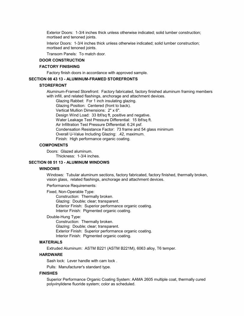
Exterior Doors: 1-3/4 inches thick unless otherwise indicated; solid lumber construction;mortised and tenoned joints.
Interior Doors: 1-3/4 inches thick unless otherwise indicated; solid lumber construction;mortised and tenoned joints.
Transom Panels: To match door.DOOR CONSTRUCTIONFACTORY FINISHING Factory finish doors in accordance with approved sample.
SECTION 08 43 13 - ALUMINUM-FRAMED STOREFRONTSSTOREFRONT Aluminum-Framed Storefront: Factory fabricated, factory finished aluminum framing members
with infill, and related flashings, anchorage and attachment devices. Glazing Rabbet: For 1 inch insulating glazing. Glazing Position: Centered (front to back). Vertical Mullion Dimensions: 2" x 6". Design Wind Load: 33 lbf/sq ft, positive and negative. Water Leakage Test Pressure Differential: 15 lbf/sq ft. Air Infiltration Test Pressure Differential: 6.24 psf. Condensation Resistance Factor: 73 frame and 54 glass minimum Overall U-Value Including Glazing: .42, maximum. Finish: High performance organic coating.
COMPONENTS Doors: Glazed aluminum.
Thickness: 1-3/4 inches.SECTION 08 51 13 - ALUMINUM WINDOWS
WINDOWS Windows: Tubular aluminum sections, factory fabricated, factory finished, thermally broken,
vision glass, related flashings, anchorage and attachment devices. Performance Requirements: Fixed, Non-Operable Type:
Construction: Thermally broken. Glazing: Double; clear; transparent. Exterior Finish: Superior performance organic coating. Interior Finish: Pigmented organic coating.Double-Hung Type: Construction: Thermally broken. Glazing: Double; clear; transparent. Exterior Finish: Superior performance organic coating. Interior Finish: Pigmented organic coating.
MATERIALS Extruded Aluminum: ASTM B221 (ASTM B221M), 6063 alloy, T6 temper.HARDWARE Sash lock: Lever handle with cam lock . Pulls: Manufacturer's standard type.FINISHES Superior Performance Organic Coating System: AAMA 2605 multiple coat, thermally cured
polyvinylidene fluoride system; color as scheduled.

Pigmented Organic Coating System: AAMA 2603; polyester or acrylic baked enamel finish;color as scheduled.
SECTION 08 71 00 - DOOR HARDWAREDOOR HARDWARE - GENERAL Provide all hardware specified or required to make doors fully functional, compliant with
applicable codes, and secure to the extent indicated. Provide products that comply with the following:
Applicable provisions of federal, state, and local codes. Fire-Rated Doors: NFPA 80.
HINGES Hinges: Provide hinges on every swinging door.
Provide five-knuckle full mortise butt hinges unless otherwise indicated. Provide ball-bearing hinges at all doors having closers. Provide hinges in the quantities indicated. Provide non-removable pins on exterior outswinging doors. Where electrified hardware is mounted in door leaf, provide power transfer hinges.
PUSH/PULLS Push/Pulls: Comply with BHMA A156.6.
Provide push and pull on doors not specified to have lockset, latchset, exit device, orauxiliary lock.
On solid doors, provide matching push plate and pull plate on opposite faces. On glazed storefront doors, provide matching push/pull bars on both faces.
LOCKS AND LATCHES Locks: Provide a lock for every door, unless specifically indicated as not requiring locking.
Hardware Sets indicate locking functions required for each door. If no hardware set is indicated for a swinging door provide an office lockset. Trim: Provide lever handle or pull trim on outside of all locks unless specifically stated to
have no outside trim. Lock Cylinders: Provide key access on outside of all locks unless specifically stated to
have no locking or no outside trim. Lock Cylinders: Manufacturer’s standard tumbler type, six-pin standard core. Keying: Grand master keyed. Latches: Provide a latch for every door that is not required to lock, unless specifically indicated
"push/pull" or "not required to latch".FLUSHBOLTS Flushbolts: Lever extension bolts in leading edge of door, one bolt into floor, one bolt into top of
frame. Pairs of Swing Doors: At inactive leaves, provide flush bolts of type as required to comply
with code. Floor Bolts: Provide dustproof strike except at metal thresholds.
CLOSERS Closers: Complying with BHMA A156.4.
Provide a door closer on every exterior door. Provide a door closer on every fire- and smoke-rated door. Spring hinges are not an
acceptable self-closing device unless specifically so indicated. On pairs of swinging doors, if an overlapping astragal is present, provide coordinator to
ensure the leaves close in proper order.STOPS AND HOLDERS

Stops: Complying with BHMA A156.8; provide a stop for every swinging door, unless otherwiseindicated. Provide wall stops, unless otherwise indicated. If wall stops are not practical, due to configuration of room or furnishings, provide
overhead stop. Stop is not required if positive stop feature is specified for door closer; positive stop feature
of door closer is not an acceptable substitute for a stop unless specifically so stated.GASKETING AND THRESHOLDS Gaskets: Complying with BHMA A156.22.
On each door in smoke partition, provide smoke gaskets; top, sides, and meeting stile ofpairs. If fire/smoke partitions are not indicated on drawings, provide smoke gaskets oneach door identified as a "smoke door" and 20-minute rated fire doors.
On each exterior door, provide weatherstripping gaskets, unless otherwise indicated; top,sides, and meeting stiles of pairs. Where exterior door is also required to have fire or smoke rating, provide gaskets
functioning as both smoke and weather seals. On each exterior door, provide door bottom sweep, unless otherwise indicated.
Thresholds: At each exterior door, provide a threshold unless otherwise indicated.
PROTECTION PLATES AND ARCHITECTURAL TRIM Protection Plates:
Kickplate: Provide on push side of every door with closer, except storefront and all-glassdoors.
SECTION 08 80 00 - GLAZINGGLASS MATERIALS Float Glass: All glazing is to be float glass unless otherwise indicated.
Annealed Type: ASTM C1036, Type I, transparent flat, Class 1 clear, Quality Q3 (glazingselect).
Heat-Strengthened and Fully Tempered Types: ASTM C1048. Tinted Types: Color and performance characteristics as indicated. Thicknesses: As indicated; for exterior glazing comply with specified requirements for
wind load design regardless of specified thickness. Laminated Glass: Float glass laminated in accordance with ASTM C1172.
Plastic Interlayer: 0.060 inch thick, minimum. Where fully tempered is specified or required, provide glass that has been tempered by the
tong-less horizontal method. Fire-Resistance-Rated Composite Glazing: Multi-layer glazing UL- or WH-listed as fire-
resistance-rated glazing and complying with 16 CFR 1201 test requirements for Category IIwithout the use of a surface-applied film.
SEALED INSULATING GLASS UNITS Sealed Insulating Glass Units: Types as indicated.
Locations: Exterior, except as otherwise indicated. Durability: Certified by an independent testing agency to comply with ASTM E2190. Edge Spacers: Aluminum, bent and soldered corners. Edge Seal: Glass to elastomer with supplementary silicone sealant.
SECTION 08 83 00 - MIRRORSMATERIALS Mirror Glass - General: Select materials and/or provide supports as required to limit mirrored
glass deflection to 1/200 or flexure limit of glass with full recovery of glazing materials,whichever is less.

GLAZING ACCESSORIES Setting Blocks: Neoprene, 80 to 90 Shore A durometer hardness. Spacer Shims: Neoprene, 50 to 60 Shore A durometer hardness. Glazing Tape: Preformed butyl compound with integral resilient tube spacing device; 10 to 15
Shore A durometer hardness; on release paper. Glazing Clips: Manufacturer's standard type. Mirror Attachment Accessories: Stainless steel clips. Mirror Adhesive: Chemically compatible with mirror coating and wall substrate.
SECTION 08 91 00 - LOUVERSLOUVERS Louvers: Factory fabricated and assembled, complete with frame, mullions, and accessories;
AMCA Certified under AMCA 511. Screens: Provide insect screens at intake louvers and bird screens at exhaust louvers.

FINISHES - 09 - 1
Simon Fairfield Library Renovation Douglas, Massachusetts
DIVISION 09 - FINISHESSECTION 09 22 16 - NON-STRUCTURAL METAL FRAMING
FRAMING MATERIALS Non-Loadbearing Framing System Components: ASTM C645; galvanized sheet steel, of size
and properties necessary to comply with ASTM C754 for the spacing indicated, with maximumdeflection of wall framing of L/360 at 7.5 psf.
Tracks and Runners: Same material and thickness as studs, bent leg retainer notched toreceive studs with provision for crimp locking to stud.
Furring and Bracing Members: Of same material as studs; thickness to suit purpose; complyingwith applicable requirements of ASTM C754.
Fasteners: ASTM C1002 self-piercing tapping screws. Acoustic Insulation: As specified in Section 07 21 00.
SECTION 09 26 13 - GYPSUM VENEER PLASTERINGMATERIALS Gypsum Veneer Plaster: ASTM C587, mixed in accordance with manufacturer's instructions. Standard Gypsum Veneer Base: ASTM C1396/C1396M; sizes to minimize joints in place; ends
square cut. Fire-Rated Gypsum Veneer Base: ASTM C1396/C1396M, fire rated Type X; sizes to minimize
joints in place; ends square cut. Gypsum Veneer Base Trim Accessories: Zinc-coated steel or plastic, complying with ASTM
C1047. Gypsum Board Accessories: Complying with ASTM C1047. Joint Reinforcing for Gypsum Veneer Base: As specified in ASTM C587. Fasteners: As specified in ASTM C844. Bond Coat: ASTM C631 bonding compound.
SECTION 09 30 00 - TILINGTILE Manufacturers: All products by the same manufacturer. Ceramic Mosaic Tile : ANSI A137.1 , and as follows:
Size and Shape: 1 inch square. Surface Finish: Slip resistant.
Glazed Wall Tile : ANSI A137.1 , and as follows: Size and Shape: 3' x 6". Surface Finish: High gloss.
TRIM AND ACCESSORIES Ceramic Accessories: Glazed finish, same color and finish as adjacent field tile; same
manufacturer as tile.Ceramic Trim: Matching bullnose, double bullnose, cove base, and cove ceramic shapes insizes coordinated with field tile.Non-Ceramic Trim: Satin brass anodized extruded aluminum, style and dimensions to suitapplication, for setting using tile mortar or adhesive.
Thresholds: Marble, white or gray, honed finish; 2 inches wide by full width of wall or frameopening; 1/2 inch thick; beveled one long edge with radiused corners on top side; without holes,cracks, or open seams.
ADHESIVE MATERIALS

2 - FINISHES - 09
Simon Fairfield Library Renovation Douglas, Massachusetts
Organic Adhesive: ANSI A136.1, thinset bond type; use Type I in areas subject to prolongedmoisture exposure.
GROUT MATERIALSStandard Grout: Any type specified in ANSI A118.6 or A118.7.
ACCESSORY MATERIALS Cementitious Backer Board: ANSI A118.9; High density, cementitious, glass fiber reinforced,
1/2 inch thick; 2 inch wide coated glass fiber tape for joints and corners.SECTION 09 51 00 - ACOUSTICAL CEILINGS
ACOUSTICAL UNITS Acoustical Units - General: ASTM E1264, Class A. Acoustical Panels Type ____: Plastic faced mineral fiber, ASTM E1264 Type IV, with the
following characteristics: Size: 24 x 24 inches. Thickness: 3/4 inches. Composition: Wet felted. Surface Color: To be selected by Architect from manufacturer's standard line. Surface Pattern: Perforated, regularly spaced large holes. Suspension System: Exposed grid.
SUSPENSION SYSTEM(S) Suspension Systems - General: ASTM C635; die cut and interlocking components, with
stabilizer bars, clips, splices, perimeter moldings, and hold down clips as required. Exposed Steel Suspension System Type ____: Formed steel, commercial quality cold rolled;
intermediate-duty. Profile: Tee; 15/16 inch wide face. Construction: Double web. Finish: White painted.
SECTION 09 64 29 - WOOD STRIP AND PLANK FLOORINGMATERIALS Wood Strip Flooring :
Species: White oak. Grade: Clear. Cut: Quarter sawn. Actual Thickness: 3/4 inch. Actual Width: 2-1/4 inches. Edge: Tongue and Groove. End: End matched. Length: Random, minimum of 48 inches. Length: ________.
Flooring Nails: Type recommended by flooring manufacturer. Sleepers and Shims: Softwood lumber, pressure treated for moisture protection, 2 x 4 inch
size. Secondary Subflooring: 23/32 inch thick plywood, APA Rated Sheathing, Span Rating of ____
with tongue and groove edges; Exposure 1 , sanded , preservative treated. Vapor Retarder: Black polyethylene sheet, 8 mil thick; 2 inch wide tape for joint sealing. Sheathing Paper: Plain building paper.
SECTION 09 65 00 - RESILIENT FLOORINGSHEET FLOORING

FINISHES - 09 - 3
Simon Fairfield Library Renovation Douglas, Massachusetts
Rubber Sheet Flooring: 100 percent rubber composition, color and pattern through totalthickness: Total Thickness: 0.125 inch minimum. Design: Flat. Pattern: Solid color.
TILE FLOORING Vinyl Composition Tile: Homogeneous, with color extending throughout thickness, and:
Minimum Requirements: Comply with ASTM F1066, of Class corresponding to typespecified.
Size: 12 x 12 inch. Thickness: 0.125 inch. Pattern: Solid color.
Rubber Tile: Homogeneous color and pattern throughout thickness, and: Minimum Requirements: Comply with ASTM F1344, of Class corresponding to type
specified. Design: Smooth. Size: 12 x 12 inch. Overall Thickness: 0.125 inch. Pattern: Solid color.
STAIR COVERING Stair Treads: Rubber; full width and depth of stair tread in one piece; tapered thickness; nosing
not less than 1-5/8 inch deep. Minimum Requirements: Comply with FS RR-T-650 requirements corresponding to type
specified. Nominal Thickness: 0.1875 inch. Nosing: Square. Style: Contrasting color abrasive grit strips full width. Color: Solid.
Stair Risers: Full height and width of tread in one piece, matching treads in material and color: Thickness: 0.080 inch.
RESILIENT BASE Resilient Base: ASTM F1861, Type TS rubber, vulcanized thermoset; top set Style B, Cove,
and as follows: Height: 4 inch. Thickness: 0.125 inch thick. Finish: Satin. Color: Color as selected from manufacturer's standards.
SECTION 09 67 14 - RESILIENT URETHANE FLOORINGMATERIALS Resilient Urethane Flooring: Fluid-applied, self-leveling urethane base coat(s) with pigmented
urethane top coat(s). Primer: 2 mils thick. Base Coat: 1 coat, 1/4 inch thick, total. Top Coat: 3 mils thick; ______ color.
SECTION 09 68 00 - CARPETINGCARPET Carpet Type ____: Tufted, nylon, conforming to the following criteria:
Color: ________. Pattern: ________. Primary Backing:

4 - FINISHES - 09
Simon Fairfield Library Renovation Douglas, Massachusetts
Material: Polypropylene. Secondary Backing:
Material: Jute. Total Weight: 30 oz/sq yd.
SECTION 09 90 00 - PAINTING AND COATINGSECTION INCLUDES Scope: Finish all interior and exterior surfaces exposed to view, unless fully factory-finished and
unless otherwise indicated, including the following: Both sides and edges of plywood backboards for electrical and telecom equipment before
installing equipment. Elevator pit ladders. Exposed surfaces of steel lintels and ledge angles. Mechanical and Electrical:
In finished areas, paint all insulated and exposed pipes, conduit, boxes, insulated andexposed ducts, hangers, brackets, collars and supports, mechanical equipment, andelectrical equipment, unless otherwise indicated.In finished areas, paint shop-primed items.
On the roof and outdoors, paint all equipment that is exposed to weather or to view,including that which is factory-finished.
Paint interior surfaces of air ducts and convector and baseboard heating cabinets thatare visible through grilles and louvers with one coat of flat black paint to visiblesurfaces.
Paint dampers exposed behind louvers, grilles, and convector and baseboardcabinets to match face panels.
Do Not Paint or Finish the Following Items: Items fully factory-finished unless specifically so indicated; materials and products having
factory-applied primers are not considered factory finished. Items indicated to receive other finishes. Items indicated to remain unfinished. Fire rating labels, equipment serial number and capacity labels, and operating parts of
equipment. Floors, unless specifically so indicated. Glass. Concealed pipes, ducts, and conduits.
MANUFACTURERS Paints:PAINTS AND COATINGS - GENERAL Volatile Organic Compound (VOC) Content:
Provide coatings that comply with the most stringent requirements specified in thefollowing: 40 CFR 59, Subpart D--National Volatile Organic Compound Emission Standards for
Architectural Coatings. Determination of VOC Content: Testing and calculation in accordance with 40 CFR 59,
Subpart D (EPA Method 24), exclusive of colorants added to a tint base and water addedat project site; or other method acceptable to authorities having jurisdiction.
PAINT SYSTEMS - SEE SECTION 09 91 00SECTION 09 91 00 - PAINTING
SECTION INCLUDES Opaque paint systems for field application.
FINISHES - 09 - 5
Simon Fairfield Library Renovation Douglas, Massachusetts
Additional product requirements, execution, and surfaces not to be finished are specified inSection 09 90 00.
MANUFACTURERS Base Manufacturer:
Pratt & Lambert Paints: www.prattandlambert.com. Products of other manufacturers may be used under conditions specified in Section 09 90
00. Primers: Where the manufacturer offers options on primers for a particular substrate, use
primer categorized as "best" by the manufacturer.

SPECIALTIES - 10 - 1
Simon Fairfield Library Renovation Douglas, Massachusetts
DIVISION 10 - SPECIALTIESSECTION 10 11 01 - VISUAL DISPLAY BOARDS
VISUAL DISPLAY BOARDS Markerboards: Porcelain enamel on steel, laminated to core.
Color: White. Frame: Extruded aluminum , with concealed fasteners. Frame Finish: Anodized, natural.
Tackboards: Fine-grained, homogeneous natural cork. Cork Thickness: 7/32 inch. Frame: Extruded aluminum , with concealed fasteners. Frame Finish: Anodized, natural.
SECTION 10 14 00 - SIGNAGESIGNAGE APPLICATIONS Accessibility Compliance: All signs are required to comply with ADAAG and ANSI/ICC A 117.1
and applicable building codes, unless otherwise indicated; in the event of conflictingrequirements, comply with the most comprehensive and specific requirements.
SIGN TYPESSECTION 10 28 00 - TOILET, BATH, AND LAUNDRY ACCESSORIES
MATERIALS Accessories - General: Shop assembled, free of dents and scratches and packaged complete
with anchors and fittings, steel anchor plates, adapters, and anchor components for installation.TOILET ROOM ACCESSORIES Toilet Paper Dispenser: Single roll, surface mounted bracket type, chrome-plated zinc alloy
brackets , spindleless type for tension spring delivery designed to prevent theft of tissue roll. Paper Towel Dispenser: Folded paper type, stainless steel, semi-recessed, with viewing slots
on sides as refill indicator and tumbler lock. Electric Hand Dryer:
Basis of Design: American Dryer, Inc; A Series: www.americandryer.com. Operation: Automatic, sensor-operated. Total Energy Usage: 2300 watts or less. Style: Horizontal - Traditional, Surface mounted.
Waste Receptacle: Wall-mounted, stainless steel, seamless lower door for access to container,with tumbler lock, reinforced panel full height of door, push-in self-closing top door, continuouslywelded bottom pan and seamless exposed flanges.
Soap Dispenser: Liquid soap dispenser, wall-mounted, surface, with stainless steel cover andhorizontal stainless steel tank and working parts; push type soap valve, check valve, andwindow gage refill indicator, tumbler lock.
Grab Bars: Stainless steel, 1-1/4 inches outside diameter, minimum 0.05 inch wall thickness,nonslip grasping surface finish, concealed flange mounting; 1-1/2 inches clearance betweenwall and inside of grab bar.
Diaper Changing Station: Wall-mounted folding diaper changing station for use in commercialtoilet facilities, meeting or exceeding ASTM F2285. Style: Horizontal. Material: Polyethylene.
SECTION 10 44 00 - FIRE PROTECTION SPECIALTIESFIRE EXTINGUISHERS

Fire Extinguishers - General: Comply with product requirements of NFPA 10 and applicablecodes, whichever is more stringent.
Dry Chemical Type Fire Extinguishers: Carbon steel tank, with pressure gage. Class: A:B:C. Size: 20 pound.
FIRE EXTINGUISHER CABINETS Metal: Formed stainless steel sheet; 0.036 inch thick base metal. Cabinet Configuration: Recessed type. Door: 0.036 inch thick, reinforced for flatness and rigidity; latch. Hinge doors for 180 degree
opening with two butt hinge. Provide nylon catch. Door Glazing: Glass, clear, 1/8 inch thick heat strengthened. Set in resilient channel gasket
glazing.
CONVEYING EQUIPMENT - 14 - 1
Simon Fairfield Library Renovation Douglas, Massachusetts
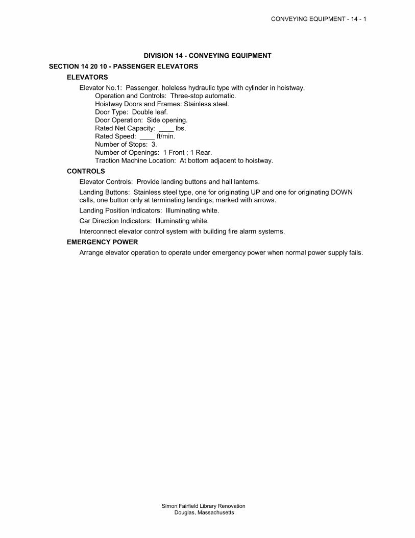
DIVISION 14 - CONVEYING EQUIPMENTSECTION 14 20 10 - PASSENGER ELEVATORS
ELEVATORS Elevator No.1: Passenger, holeless hydraulic type with cylinder in hoistway.
Operation and Controls: Three-stop automatic. Hoistway Doors and Frames: Stainless steel. Door Type: Double leaf. Door Operation: Side opening. Rated Net Capacity: ____ lbs. Rated Speed: ____ ft/min. Number of Stops: 3. Number of Openings: 1 Front ; 1 Rear. Traction Machine Location: At bottom adjacent to hoistway.
CONTROLS Elevator Controls: Provide landing buttons and hall lanterns. Landing Buttons: Stainless steel type, one for originating UP and one for originating DOWN
calls, one button only at terminating landings; marked with arrows. Landing Position Indicators: Illuminating white. Car Direction Indicators: Illuminating white. Interconnect elevator control system with building fire alarm systems.EMERGENCY POWER Arrange elevator operation to operate under emergency power when normal power supply fails.

EARTHWORK - 31 - 1
Simon Fairfield Library Renovation Douglas, Massachusetts
DIVISION 31 - EARTHWORKSECTION 31 22 00 - GRADING
MATERIALS Topsoil - Soil Type ____: Topsoil excavated on-site.
Graded. Free of roots, rocks larger than 1/2 inch, subsoil, debris, large weeds and foreign matter.
ROUGH GRADINGFINISH GRADING Fine grade topsoil to eliminate uneven areas and low spots. Maintain profiles and contour of
subgrade.SECTION 31 23 16 - EXCAVATION
EXCAVATING Excavate to accommodate new structures and construction operations. Cut utility trenches wide enough to allow inspection of installed utilities.
SECTION 31 23 16.13 - TRENCHINGFILL MATERIALS General Fill: Subsoil excavated on-site. Topsoil: See Section 31 22 00.TRENCHING Slope banks of excavations deeper than 4 feet to angle of repose or less until shored. Do not interfere with 45 degree bearing splay of foundations. Cut trenches wide enough to allow inspection of installed utilities. Hand trim excavations. Remove loose matter.BACKFILLING Backfill to contours and elevations indicated using unfrozen materials. Maintain optimum moisture content of fill materials to attain required compaction density. Compaction Density Unless Otherwise Specified or Indicated:
SECTION 31 23 23 - FILLFILL MATERIALSFILLING Fill to contours and elevations indicated using unfrozen materials. Maintain optimum moisture content of fill materials to attain required compaction density. Compaction Density Unless Otherwise Specified or Indicated:
GARCIA • GALUSKA • DESOUSA Consulting Engineers Inc.
Simon Fairfield Public Library Douglas, MA J# 879 023 00.00 L#35761/Page1/November 9, 2011
TEL 508-998-5700 FAX 508-998-0883 email: [email protected]
PLUMBING SYSTEMS
NARRATIVE REPORT
The following is the Plumbing system narrative, which defines the scope of work and capacities of the Plumbing system as well as the Basis of Design.
1. CODES
A. All work installed under Section 220000 shall comply with the MA Building Code, MA Plumbing Code and all state, county, and federal codes, laws, statutes, and authorities having jurisdiction.
2. DESIGN INTENT
A. All work is new and consists of furnishing all materials, equipment, labor, transportation,
facilities, and all operations and adjustments required for the complete and operating installation of the Plumbing work and all items incidental thereto, including commissioning and testing.
3. GENERAL
A. The Plumbing Systems that will serve the project are cold water, sanitary, waste and vent systems.
B. The Building will be serviced by Municipal water and sewer systems. C. All Plumbing in the building will conform to Accessibility Codes and to Water Conserving
sections of the Plumbing Code. 4. DRAINAGE SYSTEM
A. Soil, Waste, and Vent piping system is provided to connect to all fixtures and equipment. System runs from 10 feet outside building and terminates with stack vents through the roof. In existing building, existing drainage piping may be reused if adequately sized for intended use. Integrity of existing piping should be confirmed via video inspection.
B. New drainage system piping will be service weight cast iron piping; hub and spigot with
gaskets for below grade; no hub with gaskets, bands and damps for above grade 2” and larger. Waste and vent piping 1-1/2” and smaller will be type ‘L’ copper.
5. WATER SYSTEM
A. Existing domestic water service will be re-used. B. New cold water distribution main is provided. Non-freeze wall hydrants with integral back
flow preventers are provided along the exterior of the building. C. Domestic hot water heating will be provided by oil fired water heater equipped with
thermostatically controlled mixing devices to control water temperature to the fixtures.
GARCIA • GALUSKA • DESOUSA Consulting Engineers Inc.
Simon Fairfield Public Library Douglas, MA J# 879 023 00.00 L#35761/Page2/November 9, 2011
D. A pump will re-circulate hot water from the piping system loop. Water temperature will be 120°F to serve general use fixtures.
E. Water piping will be type ‘L’ copper with wrot copper sweat fittings, silver solder. All
piping will be insulated with 1” thick high density fiberglass. 6. FIXTURES
A. Furnish and install all fixtures, including supports, connections, fittings, and any
incidentals to make a complete installation. B. Fixtures shall be the manufacturer’s guaranteed label trademark indicating first quality.
All acid resisting enameled ware shall bear the manufacturer’s symbol signifying acid resisting material.
C. Vitreous china and acid resisting enameled fixtures, including stops, supplies and traps
shall be of one manufacturer by Kohler, American Standard, or Eljer. Supports shall be Zurn, Smith or Josam. All fixtures shall be white. Faucets shall be Speakman or Chicago.
D. Fixtures shall be scheduled as follows:
1. Water Closet
: Sloan high efficiency toilet, 1.28 gallon per flush, wall hung, vitreous china, siphon jet. Sloan manually operated 1.28 gallon per flush-flush valve.
2. Lavatory
: Sloan wall hung/countertop ADA lavatory. Sloan infra-red, sensor mixing faucet, 0.5 GPM aerator. Faucet shall be programmed for 10 second cycle.
3. Staff Sink
: Elkay ADA stainless steel countertop sink with Chicago 201A faucet with 0.5 GPM aerator.
4. Drinking Fountain
: Halsey Taylor hi-low wall mounted electric water cooler, stainless steel basin.
5. Janitor Sink
: 24 x 24 x 10 Terrazo mop receptor Stern-Williams or equal.
7. DRAINS
A. Drains are cast iron, caulked outlets, nickaloy strainers, and in waterproofed areas and roofs shall have galvanized iron clamping rings with 6 lb. lead flashings to bond 9” in all directions. Drains shall be Smith, Zurn or Josam.
8. VALVES
A. Locate all new valves so as to isolate all parts of the system. Shutoff valves 3” and smaller shall be ball valves, solder end or screwed, Apollo, or equal.
9. INSULATION
A. All new water piping shall be insulated with 1" thick snap-on fiberglass insulation Type ASJ-SSL, equal to Johns Manville Micro-Lok HP.

GARCIA • GALUSKA • DESOUSA Consulting Engineers Inc.
Simon Fairfield Public Library Douglas, MA J# 879 023 00.00 L#35761/Page3/November 9, 2011 10. CLEANOUTS
A. Cleanouts shall be full size up to 4” threaded bronze plugs located as indicated on the drawings and/or where required in soil and waste pipes.
11. ACCESS DOORS
A. Furnish access doors for access to all concealed parts of the plumbing system that
require accessibility. Co-ordinate types and locations with the Architect. 12. WATER HEATER
A. Oil fired water heater with thermostatically controlled mixing device to control water
temperature to fixtures.
GARCIA • GALUSKA • DESOUSA Consulting Engineers Inc.
Simon Fairfield Public Library Douglas, MA J# 879 023 00.00 L#35760/Page1/November 9, 2011
TEL 508-998-5700 FAX 508-998-0883 email: [email protected]
SITE UTILITY SYSTEMS
NARRATIVE REPORT The following is the Site Utility system design narrative, which defines the scope of work and capacities of the Site Utility systems. 1. CODES
A. All work installed under this DIVISION shall comply with and all local, state, and federal codes, laws, statutes, and authorities having jurisdiction.
B. The work shall be performed in accordance with local Department of Public Works
Specifications, Board of Health Regulations, and MA Highway Department Standard Specifications for Highways and Bridges.
2. STORM DRAINAGE SYSTEM
A. Storm water drainage system shall be designed in accordance with Town standards and the current edition of the Massachusetts DEP Storm Water Management Policy to mitigate storm water runoff to abutting properties. The Contractor shall prepare and submit the EPA Notice of Intent (NOI) for Storm Water Discharges Associated with Construction Activity under the EPA National Pollution Discharge Elimination System (NPDES) General Permit. Contractor shall implement a Storm Water Pollution Prevention Plan (SWPPP) per the requirements of the EPA General Permit. At project completion submit a Notice of Termination (NOT) to the EPA.
B. Storm drain piping 12” and larger shall be smooth interior corrugated HDPE pipe with
rubber gasket joints. Storm drain piping 10” and under will be ASTM-D3034 SDR35 PVC with push-on rubber ring joints.
C. Stormwater will be directed to bioretention gardens for water quality treatment,
groundwater recharge and peak flow attenuation. Catch basins and drywells to a piped drainage network will be utilized as means of overflow control. Storm water runoff rate and flood control is proposed to be provided via use of subsurface detention/infiltration beds equipped with outlet control structures.
D. Catch basins and manholes shall be at least 6 feet deep and 4 feet in diameter. Castings
shall be from the approved Mass Highway Department list. All catch basins will have 4’ sumps and be equipped with environmental hoods.
E. Water quality structures shall be provided within the storm water drainage system to
assist with TSS removal and water quality. 3. SANITARY SYSTEM
A. The sanitary system shall be designed in accordance with local DPW and Board of Health regulations.
B. Manholes shall be at least 4 feet in diameter. Castings shall be from the approved MHD
list.

GARCIA • GALUSKA • DESOUSA Consulting Engineers Inc.
Simon Fairfield Public Library Douglas, MA J# 879 023 00.00 L#35760/Page2/November 9, 2011
C. Gravity sewer piping shall be Manville ASTM-D3034 SDR-35 PVC sewer pipe D. The sanitary waste system shall discharge to the existing municipal sewer connection
located on site. 4. WATER SYSTEM
A. The existing domestic water service will remain.

GARCIA • GALUSKA • DESOUSA Consulting Engineers Inc.
Simon Fairfield Public Library Douglas, MA J# 879 023 00.00 L#35679/Page 1/November 7, 2011
The following is the HVAC system narrative, which defines the scope of work and capacities of the HVAC system as well as the Basis Of Design. 1. CODES
All work installed under Section 260000 shall comply with the Town of Douglas Building Code and all state, county, and federal codes, laws, statutes, and authorities having jurisdiction.
2. DESIGN INTENT
The work of Section 260000 is shown on the drawings and specifications. All work is new and consists of furnishing all materials, equipment, labor, transportation, facilities, and all operations and adjustments required for the complete and operating installation of the Heating, Ventilating and Air Conditioning work and all items incidental thereto, including commissioning and testing.
3. SYSTEM DESCRIPTION
1. Boiler: One (1) cast iron, hot water oil fired boilers with a power burner sized at 100% of the building heating and ventilating load of approximately 280 MBH.
2. Replace existing oil tank. Provide code compliant oil feed lines.
3. Hot Water Pumps: Two (2) inline pumps for heating system, each pump sized at one hundred percent (100%) of total system capacity of approximately 28 GPM each. One (1) pump shall be stand-by. Variable speed drives will also be provided to account for excess system pressures. Each space will have fan coils.
4. Hydronic specialties including air separator, expansion tanks and associated equipment is provided and sized corresponding to the associated power plant.
5. Floor-mounted fan coils with a hot water coil and a room sensor.
6. Toilet, Electric Room, and Mechanical Room exhaust with miscellaneous duct systems and fans.
7. Supply, return and exhaust ductwork.
8. Grilles, registers and diffusers.
9. Hot water unit heaters and fin tube radiation for bathroom, vestibule and stairwells.
10. Hot water supply and return, drain and vent piping.
11. Ductwork and piping insulation.
12. Vibration isolation and seismic restraints.
GARCIA • GALUSKA • DESOUSA Consulting Engineers Inc.
Simon Fairfield Public Library Douglas, MA J# 879 023 00.00 L#35679/Page 2/November 7, 2011
13. Water treatment system.
14. Testing and balancing of systems.
15. DDC temperature control systems.
16. Existing ductless split systems to remain.
17. Condenser to be relocated to accommodate new stairwell.
18. Provided 12,000 BTU split cooling unit for elevator machine room.
19. Boiler breeching. 4. BASIS OF DESIGN: (MASS CODE) Massachusetts Code values are listed herein based on the Town of Douglas values as
determined from table 1305.1 chapter 13. Outside: Winter -1°F, Summer 86°F DB 73°F WB Inside: Cooling, 75° for heat 72°F (50% RH) for cooling. Where cooling is being provided
unoccupied temperature setback will be provided. 5. SYSTEM DESCRIPTION A. Primary Heating System:
1. The primary building heating system shall consist of one (1) oil fired hot water heating boilers sized for 100% of the building heating and ventilation load.
2. Hot water shall be distributed to the building by two (2) in-line pumps, each sized
at 100% of the total load. One (1) pump shall be standby. Variable speed drives will be provided to relieve excess system pressure as control valves modulate throughout the system.
3. The main heating distribution system piping shall upfeed and downfeed to the units.
4. A modulating oil valve shall reset the schedule of the hot water supply temperature of the system, which shall be varied, with the outdoor air temperature.
5. Space heating shall be provided by fan coils, baseboard radiation, cabinet unit heaters, and unit heaters.
6. SEQUENCE OF OPERATION:
A. Heating Fan Coil Control

GARCIA • GALUSKA • DESOUSA Consulting Engineers Inc.
Simon Fairfield Public Library Douglas, MA J# 879 023 00.00 L#35679/Page 3/November 7, 2011
1. All controls for the individual fan coil units shall be provided by the unit manufacturer and factory installed. Controls shall include a three speed fan switch, and a modulating hot water valve. Day and night operation shall be determined by the DDC system time clock. The fan setting shall be manually selectable. The wall thermostat shall modulate the built-in modulating control valve to maintain the set-point.
B. Occupied/Unoccupied Control (DDC):
1. Each air handling unit shall be considered (1) zone. Each Occupied/unoccupied
zone shall be individually controlled via the DDC system time clock scheduling system. Each zone will have the capability of individual time scheduling with the option of temporary overriding from the DDC system time clock.
C. Exhaust Fan Control: Refer to drawings and schedules for type of control required for
each fan. Where details on the drawings call for motor operated dampers, these dampers shall be provided and wired by this contractor to open during the occupied cycle and close during the unoccupied cycle, unless otherwise noted.
1. Type I: Exhaust fan shall be interlocked with noted air handling unit (refer to schedule) to run when air handling unit runs, and de-energize when air handling unit is off.
2. Type II: Exhaust fan is controlled by space thermostat. On a rise in space
temperature, the exhaust fan shall start and make-up air dampers shall open. 3. Type III: Exhaust fan is controlled from a wall mounted switch with pilot light.
Switch and pilot light provided by Division 15, wired by Division 16. 4. Type IV: Exhaust fan is wired into lighting circuit to operate when lights are on.
Wired by Division 16. 5. Type V: Exhaust fan shall be wired into building (or zone) time clock to operate
during occupied conditions and off during unoccupied conditions.
D. Hot Water Pump Control:
1. 180 Degree Hot Water Pump Control:
a. When the outside temperature rises above 65 degrees F. (adjustable) the primary pump shall be de-energized. When the outside temperature is below 65 degrees F. (adjustable) the primary pump shall be energized. If flow is lost at the primary pump the alarm shall sound and automatic changeover shall occur. The primary/standby pumps shall also be manually selectable through a panel mounted switch. Provide pilot lights for primary/standby pump run indication, and red pilot light and audible alarm for pump failure. Above 65°F (adj.) alarms shall be automatically de-energized.
GARCIA • GALUSKA • DESOUSA Consulting Engineers Inc.
Simon Fairfield Public Library Douglas, MA J# 879 023 00.00 L#35679/Page 4/November 7, 2011
b. A system mounted sensor located in the supply water line shall monitor supply water pressure and on a rise in pressure, shall signal the panel mounted “VFD” to slow the H.H.W. pumps to maintain the supply pressure set-point on a drop in systems pressure the reverse shall occur.
E. Boiler/Combustion Air Control:
1. When the outside air rises above 65 degree F. (adjustable) the boiler burner
circuits shall be de-energized. When below 65 degrees F. (adjustable) the boiler burner unit shall be enabled. Closing of the burner contacts shall start the combustion air rooftop unit. After end switch proves the rooftop unit on then the boiler burner shall energize. The rooftop unit shall stop when the boiler burner circuit is de-energized.
F. Boiler Water Reset Control
1. The supply water temperature shall adjust by modulating the gas valve thru the
outside air sensor. Reset schedule shall be adjustable. Control panel and control devices shall be provided by boiler manufacturer.
G. Unit Heater Control: (Wall And Ceiling Cabinet Type)
1. Provide single-temperature room thermostat to cycle fan motor to maintain
constant space temperature.
2. Provide strap-on aquastat on unit return piping to de-energize fan motor when fluid temperature falls below adjustable setting of aquastat.
H. Radiation And Convector Control Day/Night)
1. Provide dual temperature room thermostat to maintain constant space
temperature by automatically changing position of modulating hot water valve.
7. TESTING, ADJUSTING, COMMISIONING AND BALANCING A. Requirements: 1. Requirements include measurement and establishment of the fluid quantities of
the mechanical systems as required to meet specifications, and recording and reporting the results.
2. Test, adjust and balance the following mechanical systems: a. Supply air systems. b. Return air systems. c. Exhaust air systems. d. Outside air systems.
GARCIA • GALUSKA • DESOUSA Consulting Engineers Inc.
Simon Fairfield Public Library Douglas, MA J# 879 023 00.00 L#35679/Page 5/November 7, 2011
e. Hydronic heating and cooling systems. f. Verify temperature control system operation. 3. Do not include: a. Testing boilers and pressure vessels for compliance with safety code. b. Installation of adjusting and balancing devices. If devices must be added
to achieve proper adjusting and balancing. Contact Mechanical Contractor and the Engineer for direction.
B. Report: 1. Format: Report forms shall be those standard forms prepared by the referenced
standard for each respective item and system to be tested, adjusted, and balanced. Bind report forms complete with schematic systems diagrams and other data in reinforced, vinyl, three-ring binders. Provide binding edge labels with the project identification and a title descriptive of the contents. Divide the contents of the binder into the below listed divisions, separated by divider tabs:
a. General Information and Summary. b. Air Systems. c. Hydronic heating and cooling systems. d. Temperature Control Systems. 2. Contents: Provide the following minimum information, forms and data: a. General Information and Summary: Inside cover sheet to identify testing,
adjusting, and balancing agency, Contractor, Owner, Architect, Engineer, and Project. Include addresses, and contact names and telephone numbers. Also include a certification sheet containing the seal and name address, telephone number, and signature of the Certified Test and Balance Engineer. Include in this division a listing of the instrumentation used for the procedures along with the proof of calibration.
b. The remainder of the report shall contain the appropriate forms
containing as a minimum, the information indicated on the standard report forms prepared by the AABC for each respective item and system.
c. Submit proof that all required instrumentation has been calibrated to
tolerances specified in the referenced standards, within a period of six months prior to starting the project.

GARCIA • GALUSKA • DESOUSA Consulting Engineers Inc.
Simon Fairfield Public Library Douglas, MA J# 879 023 00.00 L#35679/Page 6/November 7, 2011
C. Quality Assurance: 1. An independent testing, adjusting, and balancing agency certified by the AABC
or NEBB as a Test and Balance Engineer in those testing and balancing disciplines required for this project.
2. Codes and Standards: a. AABC: "National Standards For Total System Balance". b. ASHRAE: ASHRAE Handbook, 1984 Systems Volume, Chapter 37,
Testing, Adjusting, and Balancing. 3. Pre-Balancing Conference: Prior to beginning of the testing, adjusting, and
balancing procedures, schedule and conduct a conference with the Architect/Engineer and Mechanical Contractor. The objective of the conference is final coordination and verification of system operation and readiness for testing, adjusting, and balancing.
4. System Operation: Systems shall be fully operational prior to beginning
procedures. All new automatic temperature controls shall be fully operational. Test, adjust and balance the air systems before refrigerant systems. Test, adjust and balance air conditioning systems during summer season, and heating systems during winter season, including at least a period of operation at outside conditions within 5° F. wet bulb temperature of maximum summer design condition, and within 10° F. dry bulb temperature of minimum winter design condition. Take final temperature reading during seasonal operation.
D. Preliminary Procedures: 1. Air Systems: a. Obtain drawings and become thoroughly acquainted with the systems. b. Compare drawings to installed equipment and field installations. c. Walk the system from the system air handling equipment to terminal
units to determine variations in installation. d. Check filters for cleanliness. e. Check all dampers (volume and fire) for correct and locked position, and
temperature control for completeness of installation before starting fans. f. Prepare report test sheets for both fans and outlets. Obtain
manufacturer's outlet factors and recommended procedures for testing. Prepare a summation of required outlet volumes to permit a cross check with required fan volumes.

GARCIA • GALUSKA • DESOUSA Consulting Engineers Inc.
Simon Fairfield Public Library Douglas, MA J# 879 023 00.00 L#35679/Page 7/November 7, 2011
g. Determine best locations in main and branch ductwork for most accurate duct traverses. Traverses shall be performed in each supply and return duct main and sub-mains for each AHU and return air fan.
h. Place outlet dampers in the full open position. i. Prepare schematic diagrams of system "as-built" ductwork and piping
layouts to facilitate reporting. j. Verify lubrication of all motors and bearings. k. Check fan belt tension. l. Check fan rotation. 2. Hydronic Systems: a. Open valves to full open position. Close coil bypass valves. b. Remove and clean all strainers. c. Examine hydronic systems and determine if water has been treated and
cleaned. d. Check pump rotation. e. Check expansion tanks to verify noted air pressure and that the system
is completely full of water. f. Check air vents at high points of system and determine if all are installed
and operating freely. g. Set temperature controls so all coils are calling for full flow. h. Check operation of automatic bypass valves. i. Check and set operating temperatures of chillers, boilers, and heat
exchangers to design requirements. j. Verify lubrication of all motors and bearings. 3. Measurements: a. Provide all required instrumentation to obtain proper measurements,
calibrated to the tolerance specified in the referenced standards. Instruments shall be properly maintained and protected against damage.
b. Provide instruments meeting the specifications of the referenced
standards.

GARCIA • GALUSKA • DESOUSA Consulting Engineers Inc.
Simon Fairfield Public Library Douglas, MA J# 879 023 00.00 L#35679/Page 8/November 7, 2011
c. Use only those instruments, which have the maximum field measuring accuracy and are best suited to the function being measured.
d. Apply instrument as recommended by the manufacturer. e. Use instruments with minimum scale and maximum subdivisions and
with scaled ranges proper for the value being measured. f. When averaging values, take a sufficient quantity of readings, which will
result in a repeatability error of less than 5%. When measuring a single point, repeat readings until 2 consecutive identical values are obtained.
g. Take all reading with the eye at the level of the indicated value to prevent
parallax. h. Use pulsation dampeners where necessary to eliminate error involved in
estimating average of rapidly fluctuation readings.
i. Take measurements in the system where best suited to the task. E. Performing Testing, Adjusting, and Balancing: 1. Test, adjust and balance all noted systems according to SMACNA standards and
as follows: a. Perform testing and balancing procedures on each system identified, in
accordance with the detailed procedures outlined in the referenced standards.
b. Cut insulation and ductwork for installation of test probes to the minimum
extent necessary to allow adequate performance of procedures. c. Patch insulation, ductwork, and housings, using materials identical to
those removed. d. Seal ducts and test for and repair leaks. e. Seal insulation to re-establish integrity of the vapor barrier. f. Mark equipment settings, including damper control positions, valve
indicators, fan speed control levers, and similar controls and devices, to show final settings. Mark with paint or other suitable, permanent identification materials.
g. Retest, adjust and balance system subsequent to significant system
modifications, and resubmit test results.

GARCIA • GALUSKA • DESOUSA Consulting Engineers Inc.
Simon Fairfield Public Library Douglas, MA J# 879 023 00.00 L#35679/Page 9/November 7, 2011
2. System Deficiencies: a. The Contractor shall advise the Engineer of all system deficiencies in
writing. Report all motors not running, missing dampers, inoperative valves and controls, etc.
b. Upon completion of system deficiencies, Balancing Contractor shall
balance and record data. 8. OPERATION MANUALS AND MAINTENANCE MANUALS:
Refer to the contracts specifications section 01700 for a complete outline of all requirements of operations and maintenance data.
9. RECORD DRAWINGS AND CONTROL DOCUMENTS:
Refer to the contracts specifications section 01720 project record documents for a complete description of all requirements of recording as built record documents.

GARCIA • GALUSKA • DESOUSA Consulting Engineers Inc.
Simon Fairfield Public Library Douglas, MA J# 879 023 00.00 L#35657/Page 1/November 7, 2011
TEL 508-998-5700 FAX 508-998-0883 email: [email protected]
The following is the Electrical system narrative, which defines the scope of work and capacities of the Power and Lighting system as well as the Basis Of Design. 1. CODES
All work installed under Section 260000 shall comply with the Massachusetts Building Code and all state, county, and federal codes, laws, statutes, and authorities having jurisdiction.
2. DESIGN INTENT
All work is new and consists of furnishing all materials, equipment, labor, transportation, facilities, and all operations and adjustments required for the complete and operating installation of the Electrical work and all items incidental thereto, including commissioning and testing.
Capacities of systems and equipment are as specified on the drawing & schedules:
A. Electrical Distribution System:
1. New construction service ratings are designed for a minimum demand load of 10 watts/s.f. The service capacity will be sized for 600 amperes at 120/208 volt, 3∅, 4wire. New lighting and power panels will be provided to accommodate respective loads for the addition. Existing 200 amp, 120/240V, single phase 1 panelboard will be backfed from new service equipment.
2. The utility company will provide a pole mounted transformer. The entire building
will be on one secondary meter.
B. Interior Lighting System:
1. Offices and other support space lighting consist of pendant mounted indirect with 10% direct fluorescent linear luminaries with (1) T5H0 lamp and electronic ballast. Each fixture will be provided to cover 80 square feet.
2. Lighting levels shall be approximately 30 foot candles in office spaces.
3. Elevator lobby/stair lighting will be comprised of recessed down lights with
compact fluorescent lamps & electronic ballasts. The light level will be designed for approximately 20-foot candles.
4. Each toilet room will be provided with downlights for general illumination and wall
mounted fixtures over mirror. 5. Each enclosed area will be locally switched designed for multi-level controls.
Occupancy sensors in toilet rooms and offices. C. Emergency Lighting System:
1. Emergency only light fixtures and exit signs will be installed to serve egress
areas such as corridors, intervening spaces, toilets, and exit discharge exterior doors. 12 volt DC battery units will be provided.

GARCIA • GALUSKA • DESOUSA Consulting Engineers Inc.
Simon Fairfield Public Library Douglas, MA J# 879 023 00.00 L#35657/Page 2/November 7, 2011
D. Site Lighting System:
1. New fixtures for area lighting will be building mounted wall sconces at rear of
building. The exterior lighting will be connected to the automatic lighting control system for photocell on and timed off.
E. Wiring Devices:
1. Office areas will generally have (1) duplex outlet per wall. At each workstation a
double duplex receptacle will be provided.
2. Exterior weatherproof receptacles will be installed at new exterior doors.
F. Fire Alarm System:
1. A new fire alarm and detection system will be provided. The system will be of the addressable type where each device will be identified at the control panel and annunciator by device type and location to facilitate search for origin of alarms.
2. Smoke detectors will be provided in corridors, stairwells and other egress ways.
3. Speaker/strobes will be provided in egress ways, open areas and other large
spaces. Strobe only units will be provided in single toilets and conference rooms.
4. Manual pull stations will be provided at exit discharge doors.
3. Tel/Data System:
A. The tel/data system is designed for a Gigabit Ethernet backbone with 1000 Base-T connection to the work station. The high speed data transmission will allow users to retrieve data from the internet and local area network almost instantly. The data system has been designed for users to accomplish:
1. Internet access through a central router which will connect to an ISP (Internet
Service Provider). 2. Applications for word processing, spreadsheet, and alike through a central
applications server. 3. Printing of documents from any user computer connected to network printers. 4. Dedicated user space on a server for client use such as storage of electronic
files.
B. The Tel/Data system will terminate at existing MDF in basement.


![First Revision No. 39-NFPA 22-2016 [ Global Input ] · First Revision No. 39-NFPA 22-2016 ... ASTM International, 100 Barr Harbor Drive, P.O. Box C700, ... ASTM A992/A992M, ...](https://static.fdocuments.us/doc/165x107/5b3e1b5a7f8b9a9a098c44d7/first-revision-no-39-nfpa-22-2016-global-input-first-revision-no-39-nfpa.jpg)
![The Big Picture - Fairfield University · The Big Picture FAIRFIELD UNIVERSITYFAIRFIELD UNIVERSITY. FAIRFIELD UNIVERSITY ___ NIQZÅMTL ML] 1 Y ... Biochemistry Biology chemistry communication](https://static.fdocuments.us/doc/165x107/5f5ce6f6442979647317c439/the-big-picture-fairfield-university-the-big-picture-fairfield-universityfairfield.jpg)