SIMATIC TDC - cache.industry.siemens.com · TDC component may pose the risk of fire according to...
36
© Siemens AG 2015. All rights reserved A5E36484357-AA , 08/2015 1 SIMATIC TDC Rack UR6021 Product Information Legal information Warning notice system This manual contains notices you have to observe in order to ensure your personal safety, as well as to prevent damage to property. The notices referring to your personal safety are highlighted in the manual by a safety alert symbol, notices referring only to property damage have no safety alert symbol. These notices shown below are graded according to the degree of danger. DANGER indicates that death or severe personal injury will result if proper precautions are not taken. WARNING indicates that death or severe personal injury may result if proper precautions are not taken. CAUTION indicates that minor personal injury can result if proper precautions are not taken. NOTICE indicates that property damage can result if proper precautions are not taken. If more than one degree of danger is present, the warning notice representing the highest degree of danger will be used. A notice warning of injury to persons with a safety alert symbol may also include a warning relating to property damage. Qualified Personnel The product/system described in this documentation may be operated only by personnel qualified for the specific task in accordance with the relevant documentation, in particular its warning notices and safety instructions. Qualified personnel are those who, based on their training and experience, are capable of identifying risks and avoiding potential hazards when working with these products/systems. Proper use of Siemens products Note the following: WARNING Siemens products may only be used for the applications described in the catalog and in the relevant technical documentation. If products and components from other manufacturers are used, these must be recommended or approved by Siemens. Proper transport, storage, installation, assembly, commissioning, operation and maintenance are required to ensure that the products operate safely and without any problems. The permissible ambient conditions must be complied with. The information in the relevant documentation must be observed.
Transcript of SIMATIC TDC - cache.industry.siemens.com · TDC component may pose the risk of fire according to...

© Siemens AG 2015. All rights reserved A5E36484357-AA , 08/2015 1
SIMATIC TDC Rack UR6021 Product Information
Legal information Warning notice system This manual contains notices you have to observe in order to ensure your personal safety, as well as to prevent damage to property. The notices referring to your personal safety are highlighted in the manual by a safety alert symbol, notices referring only to property damage have no safety alert symbol. These notices shown below are graded according to the degree of danger.
DANGER indicates that death or severe personal injury will result if proper precautions are not taken.
WARNING indicates that death or severe personal injury may result if proper precautions are not taken.
CAUTION indicates that minor personal injury can result if proper precautions are not taken.
NOTICE indicates that property damage can result if proper precautions are not taken.
If more than one degree of danger is present, the warning notice representing the highest degree of danger will be used. A notice warning of injury to persons with a safety alert symbol may also include a warning relating to property damage.
Qualified Personnel The product/system described in this documentation may be operated only by personnel qualified for the specific task in accordance with the relevant documentation, in particular its warning notices and safety instructions. Qualified personnel are those who, based on their training and experience, are capable of identifying risks and avoiding potential hazards when working with these products/systems.
Proper use of Siemens products Note the following:
WARNING Siemens products may only be used for the applications described in the catalog and in the relevant technical documentation. If products and components from other manufacturers are used, these must be recommended or approved by Siemens. Proper transport, storage, installation, assembly, commissioning, operation and maintenance are required to ensure that the products operate safely and without any problems. The permissible ambient conditions must be complied with. The information in the relevant documentation must be observed.

Rack UR6021 2 A5E36484357-AA , 08/2015
Content 1 Introduction ................................................................................................................................................................ 4
1.1 Preface .................................................................................................................................................... 4 1.2 Security information ................................................................................................................................ 4
2 Installation and EMC guidelines ................................................................................................................................. 5 2.1 Qualified personnel ................................................................................................................................. 5 2.2 Danger and warning information ............................................................................................................. 5 2.3 Introduction ............................................................................................................................................. 6 2.4 CE label .................................................................................................................................................. 6 2.5 EMC Directive ......................................................................................................................................... 6 2.6 Low-voltage directive .............................................................................................................................. 7 2.7 Machinery directive ................................................................................................................................. 7 2.8 Installation ............................................................................................................................................... 7 2.9 Fire protection ......................................................................................................................................... 7 2.10 Control cabinet ........................................................................................................................................ 9 2.11 Equipotential bonding ............................................................................................................................ 10 2.12 Protective ground .................................................................................................................................. 16 2.13 Power losses in the control cabinet ....................................................................................................... 17 2.14 Power supply ........................................................................................................................................ 18 2.15 Rack ...................................................................................................................................................... 19 2.16 Cables ................................................................................................................................................... 19 2.17 ESD Directives ...................................................................................................................................... 21
3 General technical specifications ............................................................................................................................... 22 3.1 Climatic conditions ................................................................................................................................ 22 3.2 Electrical protection and safety requirements ....................................................................................... 23 3.3 External supply of the SIMATIC TDC modules (digital outputs) ............................................................ 23 3.4 Mechanical requirements ...................................................................................................................... 23 3.5 Electromagnetic requirements (industry) ............................................................................................... 23
4 Rack UR6021 (6DD1682-0CH3) .............................................................................................................................. 23 4.1 Areas of application ............................................................................................................................... 23 4.2 Mechanical layout ................................................................................................................................. 24 4.3 Control and display elements ................................................................................................................ 25 4.4 Status and fault displays ....................................................................................................................... 26 4.5 Power supply ........................................................................................................................................ 26 4.6 Wiring diagram ...................................................................................................................................... 27 4.7 Voltage monitoring ................................................................................................................................ 27 4.8 Battery backup ...................................................................................................................................... 28 4.9 Modules ................................................................................................................................................ 29 4.10 Power supply potentials ........................................................................................................................ 29 4.11 Ventilation/cooling ................................................................................................................................. 29
Rack UR6021 A5E36484357-AA , 08/2015 3
4.12 Technical specifications ......................................................................................................................... 31 4.13 Slot covers ............................................................................................................................................. 33
5 Service & Support .................................................................................................................................................... 34

Rack UR6021 4 A5E36484357-AA , 08/2015
1 Introduction 1.1 Preface
Purpose of product information
This product information describes the basic use and functions of the hardware component, while setting the focus on the corresponding Technology and Drive Control component SIMATIC TDC.
Basic knowledge required
This product information is intended for commissioning personnel. In order to understand this product information, you need general knowledge of automation engineering.
Scope of this product information
This product information is valid for SIMATIC D7-SYS as of version 8.1.
Special notes
The user part of this manual is intended to provide information on basic procedures, but does not contain any detailed instructions with individual step sequences. For more information on the software dialogs and their handling, refer to the Online Help.
Recycling and disposal
The products can be recycled due to their low-pollutant content. Contact a certified electronic-waste disposal company to recycle and dispose of your old equipment in an environment-friendly manner.
Additional support
● You can find information on the technical support offer in the appendix (Page 34) to this documentation.
● You can find the offer for technical documentation for the individual SIMATIC products and systems on the Internet (http://www.siemens.com/simatic-tech-doku-portal).
● You can find the online catalog and online ordering system on the Internet (http://mall.automation.siemens.com).
1.2 Security information Siemens provides products and solutions with industrial security functions that support the secure operation of plants, solutions, machines, equipment and/or networks. They are important components in a holistic industrial security concept. With this in mind, Siemens’ products and solutions undergo continuous development. Siemens recommends that you keep yourself regularly informed about product updates.
For the secure operation of Siemens products and solutions, it is necessary to take suitable preventive action (e.g. cell protection concept) and integrate each component into a holistic, state-of-the-art industrial security concept. Third-party products that may be in use should also be considered. You can find more information about industrial security on the Internet (http://www.siemens.com/industrialsecurity).
To stay informed about product updates as they occur, sign up for a product-specific newsletter. You can find more information on the Internet (http://www.siemens.com/automation/service&support).
Rack UR6021 A5E36484357-AA , 08/2015 5
2 Installation and EMC guidelines
Note These Operating Instructions do not purport to cover all details or variations in equipment, nor to provide for every possible contingency to be met in connection with installation, operation or maintenance. If you need further information or encounter special problems that are not adequately treated in the operating instructions, you can obtain the necessary information from your local Siemens office. Furthermore, the contents of these Operating Instructions shall not become a part of or modify any prior or existing agreement, commitment, or legal relationship. All obligations on the part of Siemens AG are contained in the respective sales contract which also contains the complete and solely applicable warranty conditions. These contractual guarantee provisions are neither broadened nor restricted by the text in these operating instructions.
2.1 Qualified personnel in the context of the operating manual or of warning notices on the product itself are persons familiar with installation, assembly, commissioning and operation of the product and holding qualifications appropriate to their activity, such as:
1. Trained and authorized to power up, shut down, ground and tag electrical circuits and equipment in accordance with safety standards.
2. Trained in the proper care and use of protective equipment in accordance with safety standards.
2.2 Danger and warning information
WARNING Danger, high voltage During operation of electrical devices, certain parts of these devices are necessarily under dangerous voltage. Ignorance of the safety instructions may result in severe injury or property damage. Particularly the warning notes in the corresponding Operating Instructions must be strictly observed.
NOTICE Electrostatic sensitive devices The modules contain components that are sensitive to electrostatic charge. Always discharge your body before you touch an electronic module. This can be done quite simply by touching a conductive, grounded object immediately before you handle the component (e.g. bright metal parts of the control cabinet, grounding contact of socket outlet.)
NOTICE Lifting and carrying heavy loads Note the regulations/notes on lifting and carrying heavy loads.
NOTICE Cleaning the devices Use only a vacuum cleaner and dry cloths to clean the devices.

Rack UR6021 6 A5E36484357-AA , 08/2015
2.3 Introduction
What is EMC ?
Electromagnetic compatibility (EMC) is the ability of an electrical device to function, fault-free in a specified electromagnetic environment without influencing the environment in an inadmissible fashion.
This design and EMC Directive supplements the documentation on the individual components.
The SIMATIC TDC control system consists of individual components (e.g. racks, modules, interface modules, operator control panels, position transmitters). The components can be installed in the widest range of system configurations to suit individual requirements. In an environment that contains distributed components it is imperative not to neglect interference and to conform with special installation and EMC requirements of the plant.
EMC therefore represents a quality feature for
● Intrinsic immunity to interference: Resistance against internal electrical disturbance variables
● Immunity to external interference: Resistance of the system against external electromagnetic disturbance variables
● Degree of interference emission: Environmental effects caused by electromagnetic radiation
Operational reliability and immunity to interference
The manufacturer of the control system and users (including end customers) must take specific measures in order to achieve the maximum possible operational reliability and safety and interference immunity for a complete system (control and drive system).
Proper functioning of SIMATIC TDC can only be ensured if all of these measures have been observed in compliance with legal provisions (2004/108/EC).
2.4 CE label Our products meet the requirements and protection objectives of the EC Directives listed below and comply with Harmonized European Standards (EN) for programmable controllers that were published in the Official Journals of the European Community:
● 2006/95/EC "Electrical equipment for use within specific voltage limits" (Low-voltage directive)
● 2004/108/EC "Electromagnetic Compatibility" (EMC Directive)
The EC Declarations of Conformity are available to relevant authorities at the following address:
Siemens AG
Digital Factory
Factory Automation
DF FA AS DH AMB
PO box 1963
92209 Amberg / Germany
2.5 EMC Directive SIMATIC products are designed for use in industrial environments.
Industrial aera of applicaion
● Interference emission requirements to EN 61000-6-4: 2007 + A1:2011
● Immunity to interference requirements to EN 61000-6-2: 2005
Rack UR6021 A5E36484357-AA , 08/2015 7
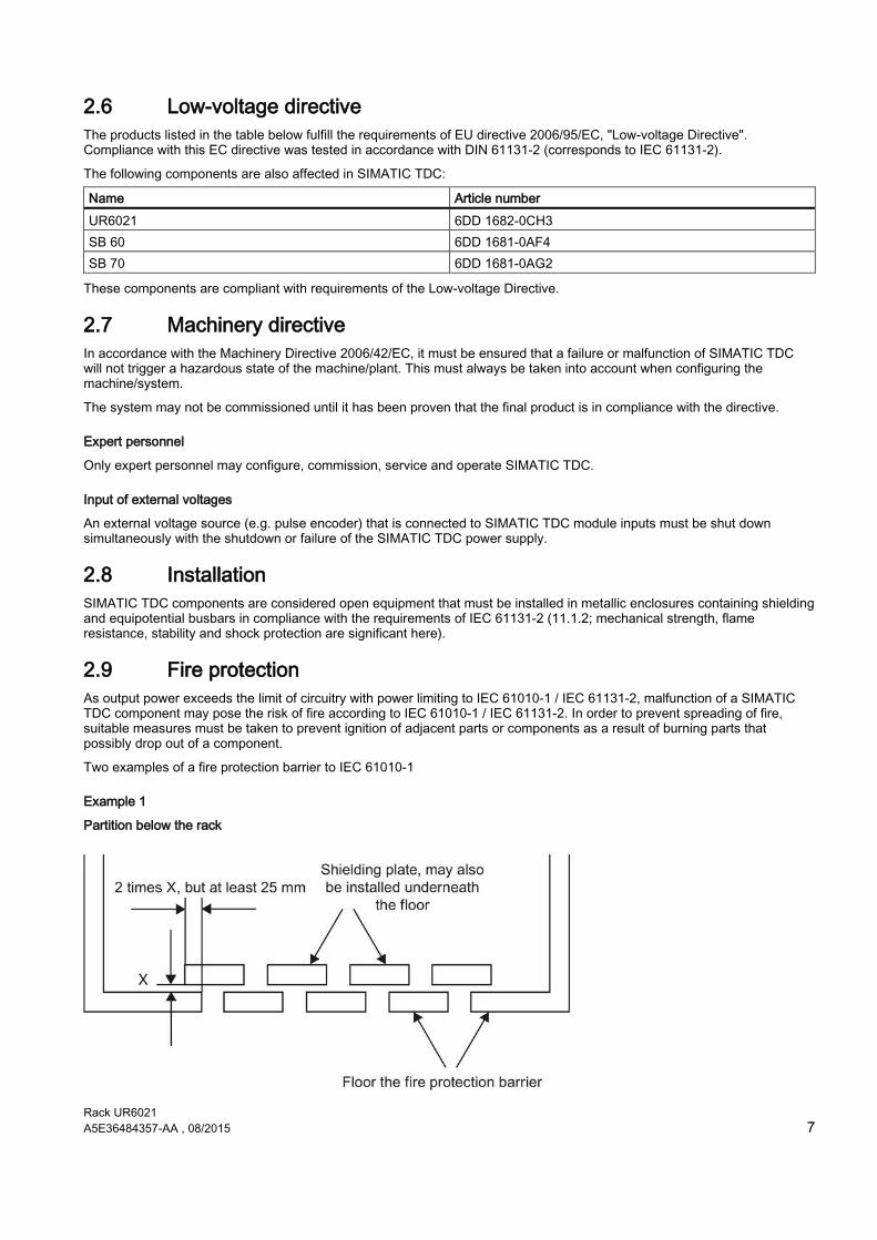
2.6 Low-voltage directive The products listed in the table below fulfill the requirements of EU directive 2006/95/EC, "Low-voltage Directive". Compliance with this EC directive was tested in accordance with DIN 61131-2 (corresponds to IEC 61131-2).
The following components are also affected in SIMATIC TDC:
Name Article number UR6021 6DD 1682-0CH3 SB 60 6DD 1681-0AF4 SB 70 6DD 1681-0AG2
These components are compliant with requirements of the Low-voltage Directive.
2.7 Machinery directive In accordance with the Machinery Directive 2006/42/EC, it must be ensured that a failure or malfunction of SIMATIC TDC will not trigger a hazardous state of the machine/plant. This must always be taken into account when configuring the machine/system.
The system may not be commissioned until it has been proven that the final product is in compliance with the directive.
Expert personnel
Only expert personnel may configure, commission, service and operate SIMATIC TDC.
Input of external voltages
An external voltage source (e.g. pulse encoder) that is connected to SIMATIC TDC module inputs must be shut down simultaneously with the shutdown or failure of the SIMATIC TDC power supply.
2.8 Installation SIMATIC TDC components are considered open equipment that must be installed in metallic enclosures containing shielding and equipotential busbars in compliance with the requirements of IEC 61131-2 (11.1.2; mechanical strength, flame resistance, stability and shock protection are significant here).
2.9 Fire protection As output power exceeds the limit of circuitry with power limiting to IEC 61010-1 / IEC 61131-2, malfunction of a SIMATIC TDC component may pose the risk of fire according to IEC 61010-1 / IEC 61131-2. In order to prevent spreading of fire, suitable measures must be taken to prevent ignition of adjacent parts or components as a result of burning parts that possibly drop out of a component.
Two examples of a fire protection barrier to IEC 61010-1
Example 1
Partition below the rack
Rack UR6021 8 A5E36484357-AA , 08/2015
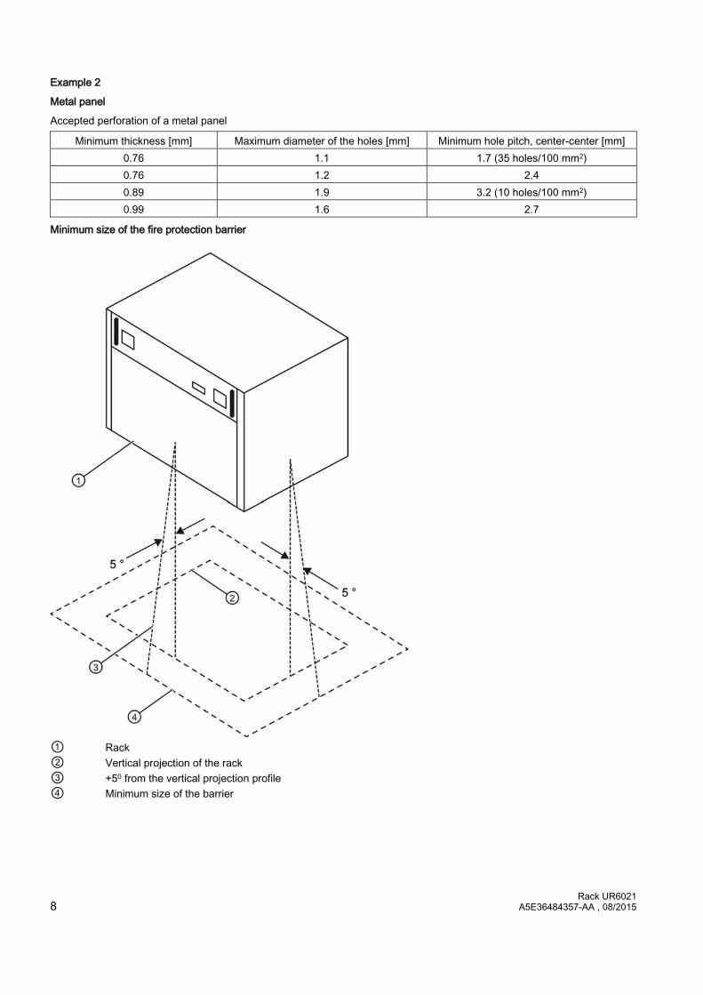
Example 2
Metal panel
Accepted perforation of a metal panel
Minimum thickness [mm] Maximum diameter of the holes [mm] Minimum hole pitch, center-center [mm] 0.76 1.1 1.7 (35 holes/100 mm2) 0.76 1.2 2.4 0.89 1.9 3.2 (10 holes/100 mm2) 0.99 1.6 2.7
Minimum size of the fire protection barrier
① Rack ② Vertical projection of the rack ③ +50 from the vertical projection profile ④ Minimum size of the barrier

Rack UR6021 A5E36484357-AA , 08/2015 9
2.10 Control cabinet ● All control cabinets must be equipped with a grounding/equipotential busbar that must be connected directly to the
cabinet frame at both ends.
● It is not allowed to operate contactors without protective circuit in a control cabinet containing SIMATIC TDC components.
● If contactors without protective circuit are operated in a control cabinet next to the SIMATIC TDC cabinet, the cabinets must be partitioned by means of a sheet steel panel.
● All control cabinets in which SIMATIC TDC components are operated must be equipped with a shielding busbar that must be connected directly at both ends to the cabinet frame.
● It is not allowed to use gas discharge lamps in the cabinet.
● The cabinet must be designed to enable unobstructed air convection.
Arrangement and clearances
The following minimum dimensions must be maintained for stacked installations of SIMATIC TDC racks:
e.g. control cabinet 2200 x 600 x 600 mm

Rack UR6021 10 A5E36484357-AA , 08/2015
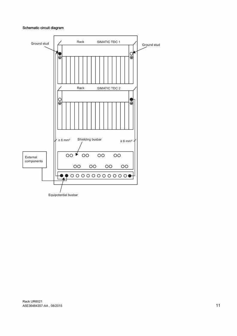
2.11 Equipotential bonding In order to ensure disturbance-free operation, the networked components may not develop different potentials. For this reason, all components must be interconnected by means of equipotential bonding with a minimum cross-section of 16 mm2.
Principle of the connection
All components (racks, power supplies, etc.) that are connected by signal cables must also be interconnected by means of equipotential bonding (exception: components with fiber-optic connections).
Equipotential busbar
An equipotential busbar should be provided in each control cabinet to facilitate wiring.
All internal and external components must be interconnected with this equipotential busbar.
Rack UR6021 A5E36484357-AA , 08/2015 11
Schematic circuit diagram

Rack UR6021 12 A5E36484357-AA , 08/2015
Practical application examples
Termination of an external shielded cable
The shield must be connected to the shielding bus.
Rack UR6021 A5E36484357-AA , 08/2015 13
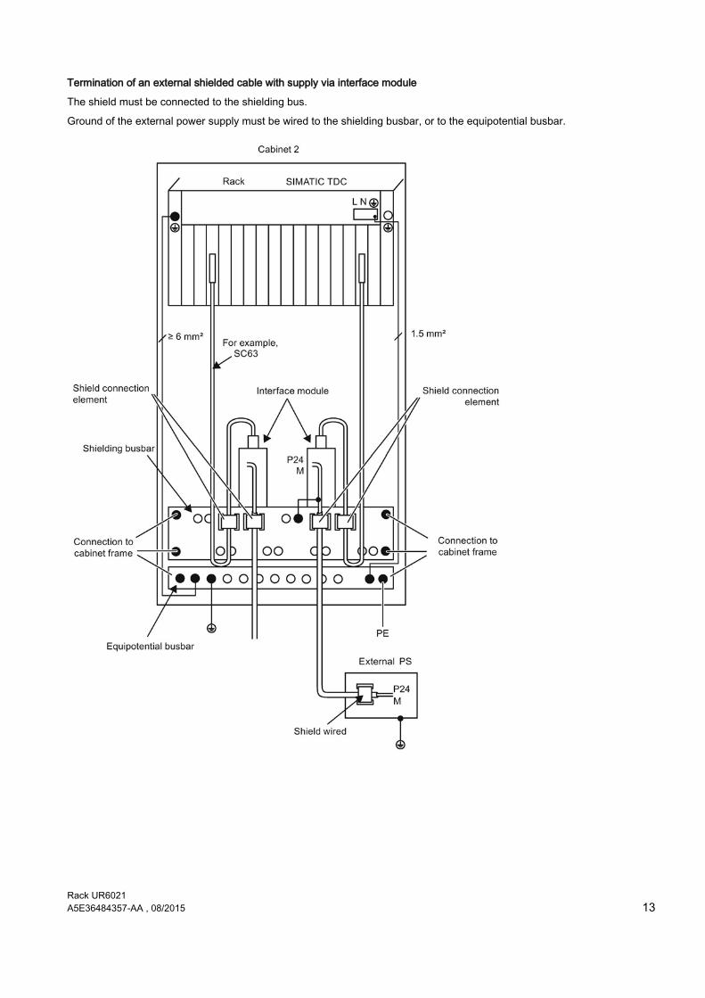
Termination of an external shielded cable with supply via interface module
The shield must be connected to the shielding bus.
Ground of the external power supply must be wired to the shielding busbar, or to the equipotential busbar.
Rack UR6021 14 A5E36484357-AA , 08/2015
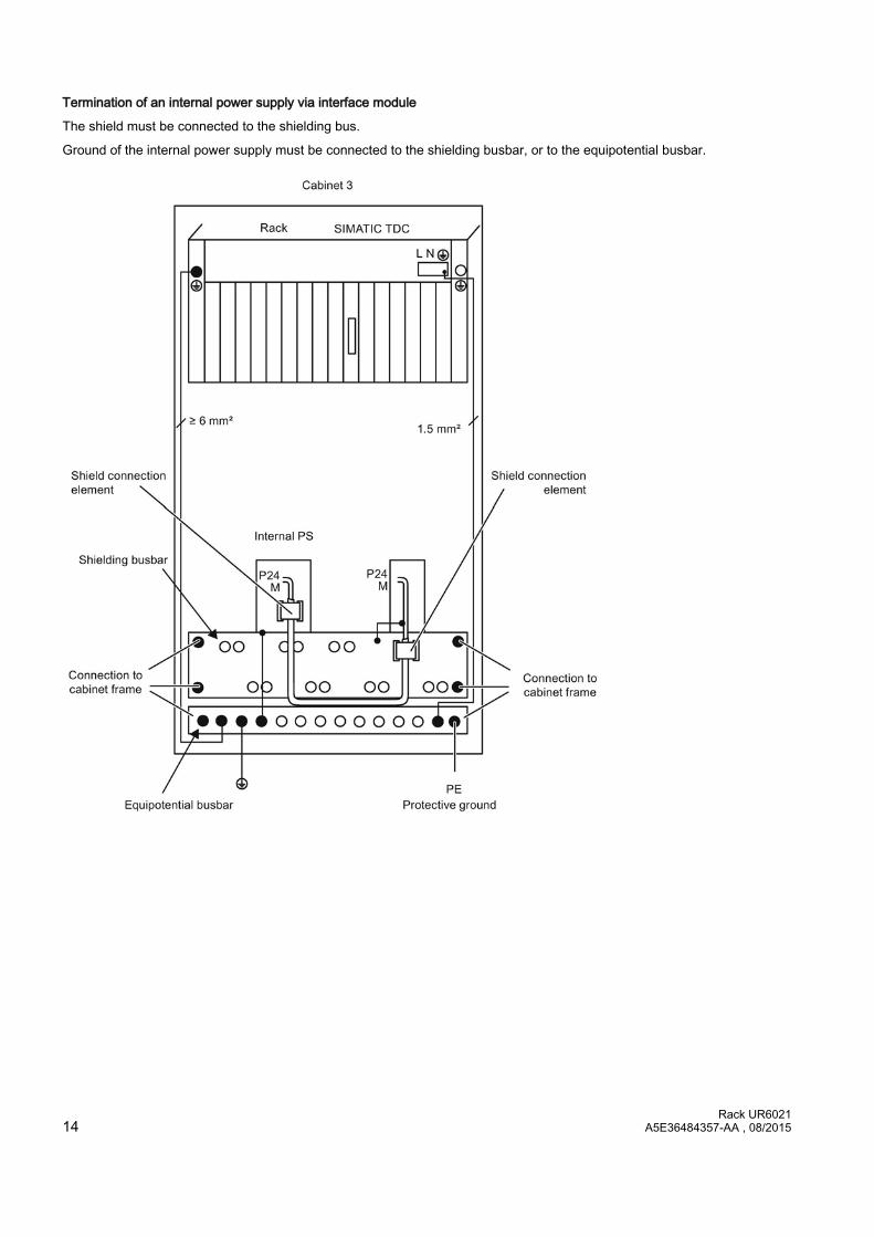
Termination of an internal power supply via interface module
The shield must be connected to the shielding bus.
Ground of the internal power supply must be connected to the shielding busbar, or to the equipotential busbar.

Rack UR6021 A5E36484357-AA , 08/2015 15
Example of grounding and potential equalization

Rack UR6021 16 A5E36484357-AA , 08/2015
2.12 Protective ground Protective ground is bonded to the cabinets or components via PE conductor. It is required in SIMATIC TDC for safe operation and as interference suppression measure.
The protective conductor must be routed and dimensioned in accordance with IEC 61131-2 (11.9).
Rack UR6021 A5E36484357-AA , 08/2015 17
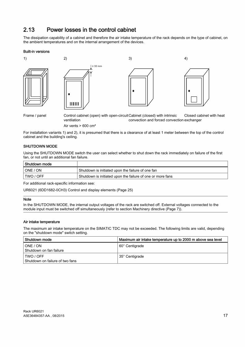
2.13 Power losses in the control cabinet The dissipation capability of a cabinet and therefore the air intake temperature of the rack depends on the type of cabinet, on the ambient temperatures and on the internal arrangement of the devices.
Built-in versions
1) 2) 3) 4)
Frame / panel Control cabinet (open) with open-circuit ventilation Air vents > 600 cm²
Cabinet (closed) with intrinsic convection and forced convection
Closed cabinet with heat exchanger
For installation variants 1) and 2), it is presumed that there is a clearance of at least 1 meter between the top of the control cabinet and the building's ceiling.
SHUTDOWN MODE
Using the SHUTDOWN MODE switch the user can select whether to shut down the rack immediately on failure of the first fan, or not until an additional fan failure.
Shutdown mode ONE / ON Shutdown is initiated upon the failure of one fan TWO / OFF Shutdown is initiated upon the failure of one or more fans
For additional rack-specific information see:
UR6021 (6DD1682-0CH3) Control and display elements (Page 25)
Note In the SHUTDOWN MODE, the internal output voltages of the rack are switched off. External voltages connected to the module input must be switched off simultaneously (refer to section Machinery directive (Page 7)).
Air intake temperature
The maximum air intake temperature on the SIMATIC TDC may not be exceeded. The following limits are valid, depending on the "shutdown mode" switch setting.
Shutdown mode Maximum air intake temperature up to 2000 m above sea level ONE / ON Shutdown on fan failure
60° Centigrade
TWO / OFF Shutdown on failure of two fans
35° Centigrade

Rack UR6021 18 A5E36484357-AA , 08/2015
2.14 Power supply
Measures against disturbance voltages
The following notes related to the EMI/EMC measures to take for systems/plants should be observed in order to avoid disturbance peaks on the supply cables in the cabinet:
Interference suppression on mains
The power supply of the rack already has a line filter with sufficient attenuation (refer to "Manufacturers declaration").
For more demanding applications, you can install an additional line filter (e.g. 250 V AC / 10 A) or overvoltage arrester in the mains line, as close as possible to the cable entry on the cabinet. Ground of the line filter/arrester must be wired to the equipotential busbar of the cabinet using the shortest possible conductor length.
24 V power supply
To attenuate external interference, a line filter must be provided for the 24 V power supply of the digital I/O (e.g. SIFI-B line filter, Order No. B84112-B-.... from Epcos/NF 1-1 line filter of Phoenix Contact). This filter should be installed as close as possible to the terminal block. The shield connections of the line filter must be bonded to ground across the shortest possible distance.
The 24 V power supply must also be equipped with lightning/overvoltage protection.
For more information, refer to the installation manual "SIMATIC Automation Systems S7-400, Hardware and Installation (http://support.automation.siemens.com/WW/view/de/1117849/0/en)".
NOTICE Network devices Safe electrical isolation to IEC 61131-2 IEC 61131-2 (11.1.2.1.3) must be ensured for all power supply units operated on SIMATIC TDC devices and modules.
Potentials of power supply
In SIMATIC TDC, the ground connections of all secondary voltages are grouped and bonded to the rack enclosure in order to improve the signal to interference ratio and to ensure proper grounding.
Rack UR6021 A5E36484357-AA , 08/2015 19
2.15 Rack ● The rack must be bonded to the grounding/equipotential busbar using the shortest possible conductor with a minimum
cross-section of 16 mm2; refer to Equipotential bonding (Page 10).
● All modules and slot covers must be screwed onto the rack. This rule also applies to commissioning phase!
● Unused slots must be provided with SIMATIC TDC slot covers SR51 6DD1682-0DA1.
● The connectors must be screwed/interlocked to the front panel.
● The limit of the air intake temperature may not be exceeded on the rack; refer to Control cabinet (Page 9). The rack must be installed in a way that safely excludes heat accumulation; refer toFire protection (Page 7).
● The air intake of the rack must be free of dust as far as possible. The air intake of the rack (bottom) must be cleaned at cyclic intervals depending on the degree of soiling.
Note
The modules may not be inserted or removed while the rack is on live voltage. Exception: Memory sub-modules MC 5xx / MMCs. As a matter of principle it is not advisable to remove and insert memory sub-modules or front connectors on the live component. For module-specific notes, refer to the corresponding user documentation (hardware).
2.16 Cables ● All signal cables you install must be shielded. All cables assembled by users must be wired with strain relief.
● Serial signal lines must be shielded. The shield must be bonded to a metalized connector housing, as well as to the shielding busbar. The cable shielding may not be wired to pin 1 of the connector.
● The power cable for the rack power supply does not require shielding. The permitted operating voltage of the power cable used may not be less than the supply voltage.
● Power supply cables for safety extra low voltages (e.g. 24 V DC) must be shielded. A power supply cable that is routed via interface module must be bonded to the shielding busbar as specified in section "Connection via interfacee module".
● External power supply ground must be bonded to the equipotential busbar; refer to "Equipotential bonding (Page 10)".
● Cables on system side and cables interconnecting the interface module with SIMATIC TDC should not be routed through the same cable duct.
● A minimum clearance of > 10 cm must be maintained between signal lines and power cables carrying voltages less than 500 V and > 30 cm to power cables carrying voltages of more than 1 kV.
Design and temperature resistance
All cables must be made of copper and be able to resist temperatures of up to at least 90 °C.

Rack UR6021 20 A5E36484357-AA , 08/2015
Connection via interface module
If interface modules are used, the shields of system-side cables and of routed the interface module to SIMATIC TDC must be bonded to ground directly above or below the interface module. Unshielded conductors that are terminated to screw terminals should be kept as short as possible.
All lines should be kept as short as possible.

Rack UR6021 A5E36484357-AA , 08/2015 21
Connector X1 (UR6021 6DD1682-0CH3 and UR5213 6DD1682-0CH2)
The cable wired to connector X1 on the rack must be shielded. The shield should be terminated as close as possible to connector X1. You can connect conductor cross-sections from 0.5 mm2 to 1.5 mm2.
Comment: We recommend using ferrules when using flexible cables.
2.17 ESD Directives Almost all of the SIMATIC TDC modules contain highly integrated components. Due to their technology, these components are highly sensitive to overvoltage and, therefore, to ESD.
ESD
The abbreviation stands for electrostatic discharge
Modules equipped with such components are identified by the following warning label on component side:
Electrostatic sensitive components can be destroyed by voltages and power levels far below human perception. Components or modules are possibly exposed to such voltages when touched by humans who have not been not electrostatically discharged. Following such voltage peaks, it is usually impossible to identify malfunction of the component immediately, as it needs an extended operating time before such malfunctions are disclosed.
Handling ESD modules
● As a matter of principle, you should never touch electronic modules unless this is unavoidable in the course of work to be carried out on the component.
● Do not touch components unless
– you are continuously grounded by means of an ESD bracelet, or
– or by wearing ESD shoes, or ESD shoe grounding strips.
● Always discharge your body before you touch an electronic module. This can be done quite simply by touching a conductive, grounded object immediately before you handle the component (e.g. bright metal parts of the control cabinet, water pipe etc.)
● Modules may not come into contact with highly insulating materials that are subject to electrostatic charge, e.g. plastic foils, insulating table plates, clothing made of artificial fiber.
● Modules must always be placed onto conductive surfaces (table with ESD mat, conductive ESD foam rubber, ESD packaging bags, ESD transport containers, cardboard or paper mats).
● Modules may not be brought close to data terminals, monitors, or television sets.
Rack UR6021 22 A5E36484357-AA , 08/2015
Measuring and modifying ESD modules
● Measurements may only be taken on the modules when
– The measuring devices is grounded (e.g. via PE conductor), or
– The measuring head has been briefly discharged (e.g. by touching a bright metal part of the control enclosure) prior to measurement with an electrically isolated measuring device.
Always use ESD soldering irons for soldering work on modules, or at least grounded soldering tips.
Shipping modules
Modules and components must always be stored and shipped in conductive packing materials (e. g. metalized plastic boxes, metal containers).
If using non-conductive packaging, you must protect the modules with a wrapping of made of conductive material, e.g. conductive foam rubber, or household aluminum foil.
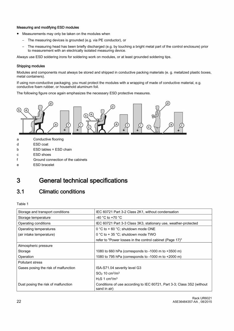
The following figure once again emphasizes the necessary ESD protective measures.
a Conductive flooring d ESD coat b ESD tables = ESD chain c ESD shoes f Ground connection of the cabinets e ESD bracelet
3 General technical specifications 3.1 Climatic conditions
Table 1
Storage and transport conditions IEC 60721 Part 3-2 Class 2K1, without condensation Storage temperature -40 °C to +70 °C Operating conditions IEC 60721 Part 3-3 Class 3K3, stationary use, weather-protected Operating temperatures (air intake temperature)
0 °C to + 60 °C; shutdown mode ONE 0 °C to + 35 °C; shutdown mode TWO refer to "Power losses in the control cabinet (Page 17)"
Atmospheric pressure Storage Operation
1080 to 660 hPa (corresponds to -1000 m to +3500 m) 1080 to 795 hPa (corresponds to -1000 m to +2000 m)
Pollutant stress Gases posing the risk of malfunction Dust posing the risk of malfunction
ISA-S71.04 severity level G3 SO2 10 cm3/m3 H2S 1 cm3/m3 Conditions of use according to IEC 60721, Part 3-3; Class 3S2 (without sand in air)
Rack UR6021 A5E36484357-AA , 08/2015 23
3.2 Electrical protection and safety requirements Safety regulations IEC 61131-2 Protection class Protection class I (with PE/ground conductor) Protection against the ingress of foreign parti-cles and water
IP 20
3.3 External supply of the SIMATIC TDC modules (digital outputs) Safety extra low voltage (SELV/PELV circuit) to IEC 60364-4-41.
3.4 Mechanical requirements The following table provides information on the type and scope of checks regarding mechanical ambient conditions.
Tested for Test standard Note Vibrations Vibration test according to
IEC 60068-2-6 (sine) Type of vibration: Frequency cycles with a rate of change of 1 octave/minute 10 Hz ≤ f ≤ 58 Hz, constant amplitude 0.075 mm 58 Hz ≤ f ≤ 150 Hz, constant acceleration 1 g Duration of vibration: 10 frequency cycles per axis in each of the 3 axes which are perpendicular to each other
Shock Shock test according to IEC 60068-2-27
Type of shock: half-sine Strength of shock: 15 g peak value, 11 ms duration Shock direction: 3 shocks each in +/– direction in each of the three perpendicular axes
3.5 Electromagnetic requirements (industry) Interference emission EN 61000-6-4 : 2007 + A1:2011 Immunity to interference EN 61000-6-2 : 2005
NOTICE Using two-way radios and mobile telephones The use of two-way radios and mobile phones in the immediate range of SIMATIC TDC can influence the operation of the device.
4 Rack UR6021 (6DD1682-0CH3) 4.1 Areas of application Rack UR6021 with 21 slots forms the mechanical base for SIMATIC TDC
The system power supply is installed in the rear area of rack.
There is a fan tray in the upper part of the rack, which includes the monitoring and signaling functions in addition to the fans.
The fan tray can be ordered as spare part (6DD1683-0CH3) and can be replaced by qualified personnel.
A high-performance 64-bit backplane bus supports high-speed data exchange between the inserted modules.
For fast, direct communication between future CPU modules, the rack UR6021 has a P0 connector in slots 01, 02, 03, 04, 09, 11, 13 and 15.
Rack UR6021 24 A5E36484357-AA , 08/2015
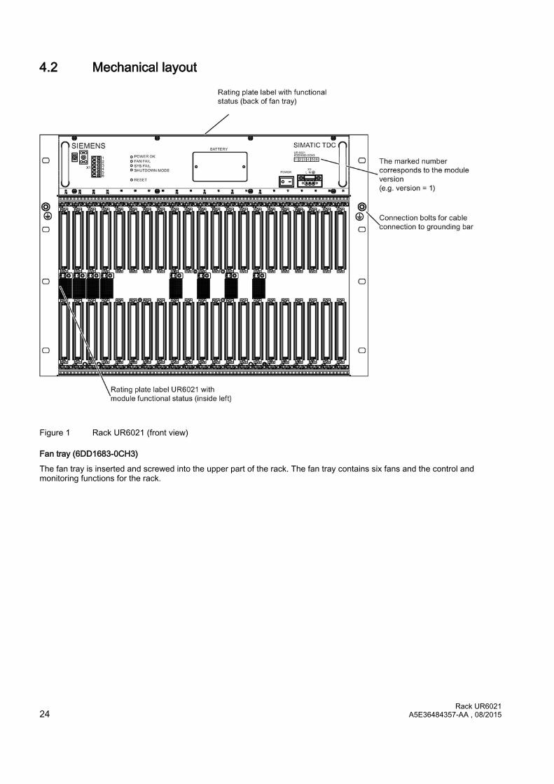
4.2 Mechanical layout
Figure 1 Rack UR6021 (front view)
Fan tray (6DD1683-0CH3)
The fan tray is inserted and screwed into the upper part of the rack. The fan tray contains six fans and the control and monitoring functions for the rack.

Rack UR6021 A5E36484357-AA , 08/2015 25
4.3 Control and display elements
X1
3 signaling relays, 230 V AC floating potential (3 x 2 contacts)
Note Mixed assignment Contacts consisting of combinations of safety extra-low voltage and hazardous voltages are not permitted.
SHUTDOWN MODE
A system shutdown mode can be set in accordance with the switch position S1.1 (in the battery compartment) as response to the failure of one or two fans.
● OFF = Shutdown on failure of two fans (SHUTDOWN MODE LED = on)
● ON = Shutdown on failure of one fan (SHUTDOWN MODE LED = flashes)
Figure 2 Front view of the fan tray
LED
The four LEDs signal the operating state of the rack.
RESET
You can restart all modules by pressing the submerged pushbutton (rack RESET).
BATTERY
Backup battery compartment (1 x AA lithium battery)
X2
Line voltage connection
Rack UR6021 26 A5E36484357-AA , 08/2015
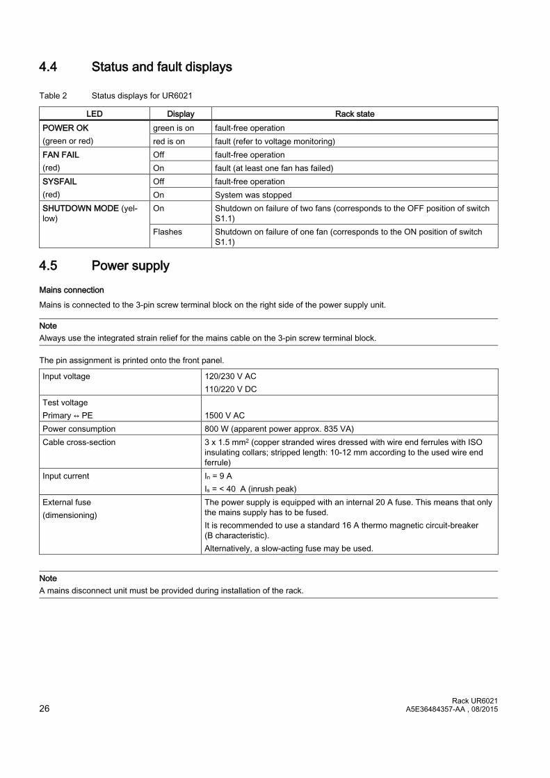
4.4 Status and fault displays
Table 2 Status displays for UR6021
LED Display Rack state POWER OK (green or red)
green is on fault-free operation red is on fault (refer to voltage monitoring)
FAN FAIL (red)
Off fault-free operation On fault (at least one fan has failed)
SYSFAIL (red)
Off fault-free operation On System was stopped
SHUTDOWN MODE (yel-low)
On Shutdown on failure of two fans (corresponds to the OFF position of switch S1.1)
Flashes Shutdown on failure of one fan (corresponds to the ON position of switch S1.1)
4.5 Power supply
Mains connection
Mains is connected to the 3-pin screw terminal block on the right side of the power supply unit.
Note Always use the integrated strain relief for the mains cable on the 3-pin screw terminal block.
The pin assignment is printed onto the front panel.
Input voltage 120/230 V AC 110/220 V DC
Test voltage Primary ↔ PE
1500 V AC
Power consumption 800 W (apparent power approx. 835 VA) Cable cross-section 3 x 1.5 mm2 (copper stranded wires dressed with wire end ferrules with ISO
insulating collars; stripped length: 10-12 mm according to the used wire end ferrule)
Input current In = 9 A Is = < 40 A (inrush peak)
External fuse (dimensioning)
The power supply is equipped with an internal 20 A fuse. This means that only the mains supply has to be fused. It is recommended to use a standard 16 A thermo magnetic circuit-breaker (B characteristic). Alternatively, a slow-acting fuse may be used.
Note A mains disconnect unit must be provided during installation of the rack.
Rack UR6021 A5E36484357-AA , 08/2015 27
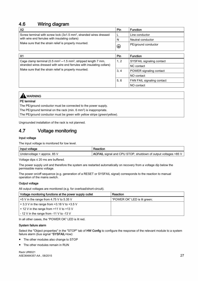
4.6 Wiring diagram X2 Pin Function Screw terminal with screw lock (3x1.5 mm2, stranded wires dressed with wire end ferrules with insulating collars) Make sure that the strain relief is properly mounted.
L Line conductor N Neutral conductor
PE/ground conductor
X1 Pin Function Cage clamp terminal (0.5 mm2 –-1.5 mm2, stripped length 7 mm, stranded wires dressed with wire end ferrules with insulating collars) Make sure that the strain relief is properly mounted.
1, 2 SYSFAIL signaling contact NC contact
3, 4 POWER signaling contact NO contact
5, 6 FAN FAIL signaling contact NO contact
WARNING PE terminal The PE/ground conductor must be connected to the power supply. The PE/ground terminal on the rack (min. 6 mm2) is inappropriate. The PE/ground conductor must be green with yellow stripe (green/yellow).
Ungrounded installation of the rack is not planned.
4.7 Voltage monitoring Input voltage
The input voltage is monitored for low level.
Input voltage Reaction Undervoltage < approx. 85 V ACFAIL signal and CPU STOP, shutdown of output voltages <85 V
Voltage dips ≤ 20 ms are buffered.
The power supply unit and therefore the system are restarted automatically on recovery from a voltage dip below the permissible mains voltage.
The power on/off sequence (e.g. generation of a RESET or SYSFAIL signal) corresponds to the reaction to manual operation of the mains switch.
Output voltage
All output voltages are monitored (e.g. for overload/short-circuit).
Voltage monitoring functions at the power supply outlet Reaction +5 V in the range from 4.75 V to 5.35 V “POWER OK” LED is lit green; + 3.3 V in the range from +3.18 V to +3.5 V + 12 V in the range from +11 V to +13 V - 12 V in the range from -11 V to -13 V
In all other cases, the “POWER OK” LED is lit red.
System failure alarm
Select the "Object properties" in the "STOP" tab of HW Config to configure the response of the relevant module to a system failure alarm (bus signal *SYSFAIL=low):
● The other modules also change to STOP
● The other modules remain in RUN
Rack UR6021 28 A5E36484357-AA , 08/2015
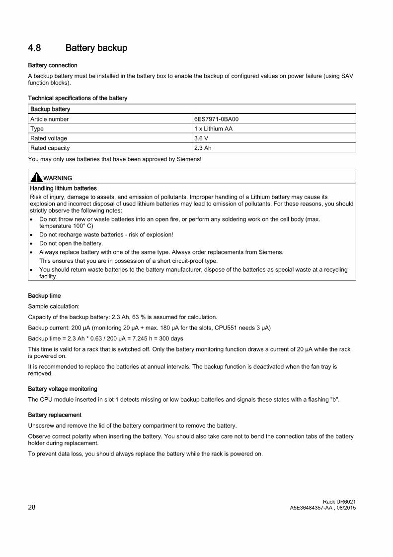
4.8 Battery backup
Battery connection
A backup battery must be installed in the battery box to enable the backup of configured values on power failure (using SAV function blocks).
Technical specifications of the battery
Backup battery Article number 6ES7971-0BA00 Type 1 x Lithium AA Rated voltage 3.6 V Rated capacity 2.3 Ah
You may only use batteries that have been approved by Siemens!
WARNING Handling lithium batteries Risk of injury, damage to assets, and emission of pollutants. Improper handling of a Lithium battery may cause its explosion and incorrect disposal of used lithium batteries may lead to emission of pollutants. For these reasons, you should strictly observe the following notes: • Do not throw new or waste batteries into an open fire, or perform any soldering work on the cell body (max.
temperature 100° C) • Do not recharge waste batteries - risk of explosion! • Do not open the battery. • Always replace battery with one of the same type. Always order replacements from Siemens.
This ensures that you are in possession of a short circuit-proof type. • You should return waste batteries to the battery manufacturer, dispose of the batteries as special waste at a recycling
facility.
Backup time
Sample calculation:
Capacity of the backup battery: 2.3 Ah, 63 % is assumed for calculation.
Backup current: 200 µA (monitoring 20 µA + max. 180 µA for the slots, CPU551 needs 3 µA)
Backup time = 2.3 Ah * 0.63 / 200 µA = 7.245 h = 300 days
This time is valid for a rack that is switched off. Only the battery monitoring function draws a current of 20 µA while the rack is powered on.
It is recommended to replace the batteries at annual intervals. The backup function is deactivated when the fan tray is removed.
Battery voltage monitoring
The CPU module inserted in slot 1 detects missing or low backup batteries and signals these states with a flashing "b".
Battery replacement
Unscsrew and remove the lid of the battery compartment to remove the battery.
Observe correct polarity when inserting the battery. You should also take care not to bend the connection tabs of the battery holder during replacement.
To prevent data loss, you should always replace the battery while the rack is powered on.

Rack UR6021 A5E36484357-AA , 08/2015 29
4.9 Modules Make sure that the modules you insert are properly aligned in their relevant slot.
NOTICE Damaging of the ESD braid Do not push the modules towards the left when inserting these, because you would risk damage to the ESD braid of the modules already inserted. Observe this particularly at slot 1, as a metal spring has been installed in this slot. If the ESD braid or a metal spring is severely damaged, the module can no longer be used because there is a risk of a short circuit with the potentials of a neighboring module.
4.10 Power supply potentials In SIMATIC TDC, the ground connections of all secondary voltages are grouped and bonded to the rack enclosure in order to improve the signal to interference ratio and to ensure proper grounding.
4.11 Ventilation/cooling The rack is equipped with a fan tray with 6 fans for forced convection of the modules and the system power supply.
Since the rack is not equipped with an air filter, you should provide a filter on the cabinet if necessary.
Note For more information, refer to section "Control cabinet (Page 9)".
Fan monitor
The fans are monitored (speed). Activation of the monitoring function is delayed in order to enable the reliable startup of the rack after you switched on power.
On failure of one or two fans, the power supply is shut down depending on the operating mode in order to prevent thermal destruction of the modules.
The operating mode (SHUTDOWN MODE) is selected using switch S1.1, which is integrated in the power supply. The power supply is switched off if one fan has failed and switch position "ON" is set, or if two fans have failed and switch position "OFF" is set (default setting).
NOTICE Safe isolation from supply Switch off power to the rack before you remove the screws of the battery compartment.
The battery compartment cover must be unscrewed to actuate switch S1.
NOTICE ESD Directives Observe the corresponding ESD directives.
The operating mode setting is indicated by the "SHUTDOWN MODE" LED on the front panel.

Rack UR6021 30 A5E36484357-AA , 08/2015
See section "Status and fault displays (Page 26)".
NOTICE Forced cooling If the modules require forced cooling, always set the "SHUTDOWN MODE" slide switch S1.1 to "ON" for air intake temperatures from 0 °C to 60 °C. You may only set the position of switch S1.1 to "OFF" if it can be ensured that the air intake temperature at the rack does not exceed 50 °C. The power supply is not shut down on failure of a single fan, but the corresponding backplane bus signal (FANAL*) is activated and can be detected by the configuration software.
Replacing the fan tray
The fan tray is can be ordered as a replacement part and be replaced.
Fan try Article number 6DD1683-0CH3
Electrostatic sensitive components can be destroyed by voltages and power levels far below human perception. Components or modules are possibly exposed to such voltages when touched by humans who have not been not electrostatically discharged. Following such voltage peaks, it is usually impossible to identify malfunction of the component immediately, as it needs an extended operating time before such malfunctions are disclosed.
NOTICE Replacing the fan tray If the fan tray is damaged, it may not be installed.
Proceed as follows to replace the fan tray:
1. Make sure that the leads to X2 and possibly X1 are de-energized and secure them against reconnection.
2. Ensure that adjacent live parts cannot be touched.
3. Remove the power connector X2.
4. If necessary, remove the wires to X1 (including the strain relief and shield connection).
5. Loosen the 8 screws on the top and bottom of the fan tray.
6. Pull the fan tray out of the rack by the handles.
CAUTION Sharp-edged front panel The edges and corners of the front plate of the fan tray may cause injury. Use suitable protective gloves to remove and install it.
7. Slide the new fan tray into the rack until it clicks and the faceplate is flush to the front panel.
8. Fasten the fan tray (8 screws on the top and bottom of the fan tray).
9. Insert a new backup battery; see section "Battery backup (Page 28)".
10. If necessary, connect the wires to X1 (including the strain relief and shield connection).
11. Connect the power connector X2.
12. Switch on the power again.

Rack UR6021 A5E36484357-AA , 08/2015 31
Signaling relay
Three 230 V signaling relays with floating potential facilitate external evaluation of the rack system states.
NOTICE Assignment of the contacts Contacts consisting of combinations of safety extra-low voltage and hazardous voltages are not permitted.
Signaling relay Terminal X1 Contact in switched off state Contact in error-free op-eration
LED in error-free operation
SYSFAIL 1.2 Closed Closed Off POWER 3.4 Open Closed green is on FAN FAIL 5.6 Open Closed Off
4.12 Technical specifications Article number
Rack UR6021 6DD1682-0CH3
General data
Safety EN 61131-2 Degree of protection IP 20 Protection class Protection class 1 with PE/ground conductor
Storage temperatures -40 °C to +70 °C Operating temperatures 0 °C to +60 °C Relative air humidity 5 % to 95 %, no condensation Atmospheric pressure Operation: 1080 hPa to 795 hPa
Storage: 1080 hPa to 660 hPa
Power input
Rated input voltage • Rated value
• Permissible range
• 120 V AC to 230 V AC
110 V DC to 220 V DC • 85 V AC to 264 V AC (wide-range input)
93.5 V DC to 253 V DC Rated input current • At 120 V AC • At 230 V AC • At 110 V DC • At 220 V DC
• 6.7 A • 3.5 A • 7.3 A • 3.7 A
Max. inrush current < 40 A Line frequency • Rated value (AC)
(DC) • Permissible range
• 50/60 Hz
(0 Hz) • 47-63 Hz
Power factor EN 61000-3-2 Pollution degree 2 Overvoltage category II Power failure backup min. 20 ms
Rack UR6021 32 A5E36484357-AA , 08/2015
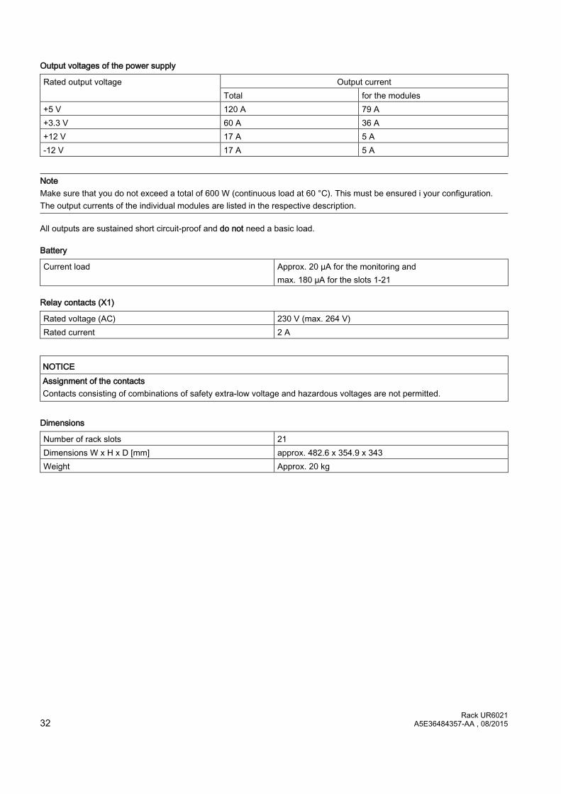
Output voltages of the power supply
Rated output voltage Output current Total for the modules
+5 V 120 A 79 A +3.3 V 60 A 36 A +12 V 17 A 5 A -12 V 17 A 5 A
Note Make sure that you do not exceed a total of 600 W (continuous load at 60 °C). This must be ensured i your configuration. The output currents of the individual modules are listed in the respective description.
All outputs are sustained short circuit-proof and do not need a basic load.
Battery
Current load Approx. 20 µA for the monitoring and max. 180 µA for the slots 1-21
Relay contacts (X1)
Rated voltage (AC) 230 V (max. 264 V) Rated current 2 A
NOTICE Assignment of the contacts Contacts consisting of combinations of safety extra-low voltage and hazardous voltages are not permitted.
Dimensions
Number of rack slots 21 Dimensions W x H x D [mm] approx. 482.6 x 354.9 x 343 Weight Approx. 20 kg
Rack UR6021 A5E36484357-AA , 08/2015 33
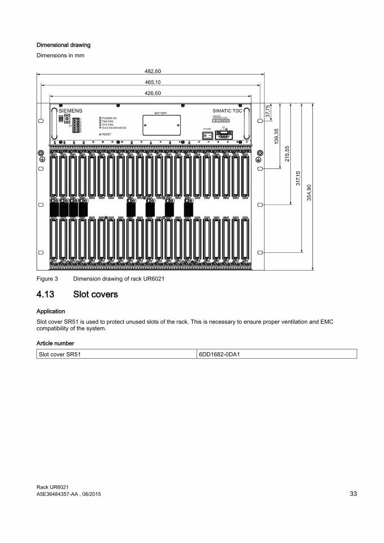
Dimensional drawing
Dimensions in mm
Figure 3 Dimension drawing of rack UR6021
4.13 Slot covers
Application
Slot cover SR51 is used to protect unused slots of the rack. This is necessary to ensure proper ventilation and EMC compatibility of the system.
Article number
Slot cover SR51 6DD1682-0DA1

Rack UR6021 34 A5E36484357-AA , 08/2015
5 Service & Support
The unmatched complete service for the entire life cycle
For machine constructors, solution providers and plant operators: The service offering from Siemens Industry Automation and Drive Technologies includes comprehensive services for a wide range of different users in all sectors of the manufacturing and process industry.
To accompany our products and systems, we offer integrated and structured services that provide valuable support in every phase of the life cycle of your machine or plant – from planning and implementation through commissioning as far as maintenance and modernization.
Our Service & Support accompanies you worldwide in all matters concerning automation and drive technology from Siemens. We provide direct on-site support in more than 100 countries through all phases of the life cycle of your machines and plants.
You have an experienced team of specialists at your side to provide active support and bundled know-how. Regular training courses and intensive contact with our employees – even across continents – ensure reliable service in a wide variety of areas.
Online Support
The comprehensive online information platform supports you in all aspects of our Service & Support at any time and from any location in the world.
You can find Online Support on the Internet at the following address: Internet (http://www.siemens.com/automation/service&support).
Technical Consulting
Support in planning and designing your project: From detailed actual-state analysis, definition of the goal and consultation on product and system questions right through to the creation of the automation solution.
Technical Support
Expert advice on technical questions with a wide range of demand-optimized services for all our products and systems.
You can find Technical Support on the Internet at the following address: Internet (http://www.siemens.com/automation/support-request).

Rack UR6021 A5E36484357-AA , 08/2015 35
Training
Extend your competitive edge – through practical know-how directly from the manufacturer.
You can find the training courses we offer on the Internet at the following address: Internet (http://www.siemens.com/sitrain).
Engineering Support
Support during project engineering and development with services fine-tuned to your requirements, from configuration through to implementation of an automation project.
Field Service
Our Field Service offers you services for commissioning and maintenance – to ensure that your machines and plants are always available.
Spare parts
In every sector worldwide, plants and systems are required to operate with constantly increasing reliability. We will provide you with the support you need to prevent a standstill from occurring in the first place: with a worldwide network and optimum logistics chains.
Repairs
Downtimes cause problems in the plant as well as unnecessary costs. We can help you to reduce both to a minimum – with our worldwide repair facilities.
Optimization
During the service life of machines and plants, there is often a great potential for increasing productivity or reducing costs.
To help you achieve this potential, we are offering a complete range of optimization services.
Modernization
You can also rely on our support when it comes to modernization – with comprehensive services from the planning phase all the way to commissioning.
Service programs
Our service programs are selected service packages for an automation and drives system or product group. The individual services are coordinated with each other to ensure smooth coverage of the entire life cycle and support optimum use of your products and systems.
The services of a Service Program can be flexibly adapted at any time and used separately.
Examples of service programs:
● Service contracts
● Plant IT Security Services
● Life Cycle Services for Drive Engineering
● SIMATIC PCS 7 Life Cycle Services
● SINUMERIK Manufacturing Excellence
● SIMATIC Remote Support Services
Advantages at a glance:
● Reduced downtimes for increased productivity
● Optimized maintenance costs due to a tailored scope of services
● Costs that can be calculated and therefore planned
● Service reliability due to guaranteed response times and spare part delivery times
● Customer service personnel will be supported and relieved of additional tasks
● Comprehensive service from a single source, fewer interfaces and greater expertise

Rack UR6021 36 A5E36484357-AA , 08/2015
Contact
At your service locally, around the globe: your partner for consultation, sales, training, service, support, spare parts... for the entire range of products supplied by Industry Automation and Drive Technologies.
You can find your personal contact in our contacts database at: Internet (http://www.siemens.com/automation/partner).
Rack UR6021 A5E36484357-AA , 08/2015
Trademarks All names identified by ® are registered trademarks of Siemens AG. The remaining trademarks in this publication may be trademarks whose use by third parties for their own purposes could violate the rights of the owner.
Disclaimer of Liability We have reviewed the contents of this publication to ensure consistency with the hardware and software described. Since variance cannot be precluded entirely, we cannot guarantee full consistency. However, the information in this publication is reviewed regularly and any necessary corrections are included in subsequent editions.
Siemens AG Division Digital Factory Postfach 48 48 90026 NÜRNBERG