SIMATIC WinCC in the Totally Integrated Automation Portal ...
Functional Example AS-FE-I-006-V20-EN
SIMATIC Safety Integrated for Factory Automation
Two-Hand Control Panel with Integrated Emergency Stop
in Category 4 According to EN 954-1: 1996 (with evaluation according to EN 62061
and EN ISO 13849-1 2006)

Two-Hand Control Panel with Integrated Emergency Stop in Category 4 / PL e / SIL 3
Entry ID: 21331100
A&D Safety Integrated Page 2/38 AS-FE-I-006-V20-EN
Cop
yrig
ht ©
Sie
men
s A
G 2
007
All
right
s re
serv
ed
2133
1100
_as_
fe_i
_006
_v20
_en_
2han
d.do
c
Preliminary remark The Functional Examples dealing with “Safety Integrated” are fully functional and tested automation configurations based on A&D standard products for simple, fast and inexpensive implementation of automation tasks in safety engineering. Each of these Functional Examples covers a frequently occurring subtask of a typical customer problem in safety engineering. Aside from a list of all required software and hardware components and a description of the way they are connected to each other, the Functional Examples include the tested and commented code. This ensures that the functionalities described here can be reset in a short period of time and thus also be used as a basis for individual expansions.
Important note The Safety Functional Examples are not binding and do not claim to be complete regarding the circuits shown, equipping and any eventuality. The Safety Functional Examples do not represent customer-specific solutions. They are only intended to provide support for typical applications. You are responsible for ensuring that the described products are used correctly.
These Safety Functional Examples do not relieve you of the responsibility of safely and professionally using, installing, operating and servicing equipment. When using these Safety Functional Examples, you recognize that Siemens cannot be made liable for any damage/claims beyond the liability clause described. We reserve the right to make changes to these Safety Functional Examples at any time without prior notice. If there are any deviations between the recommendations provided in these Safety Functional Examples and other Siemens publications – e.g. Catalogs – the contents of the other documents have priority.

Two-Hand Control Panel with Integrated Emergency Stop in Category 4 / PL e / SIL 3
Entry ID: 21331100
A&D Safety Integrated Page 3/38 AS-FE-I-006-V20-EN
Cop
yrig
ht ©
Sie
men
s A
G 2
007
All
right
s re
serv
ed
2133
1100
_as_
fe_i
_006
_v20
_en_
2han
d.do
c
Table of Contents
1 Warranty, Liability and Support .................................................................... 4
2 Automation Function...................................................................................... 5 2.1 Description of the functionality.......................................................................... 5 2.1.1 Preliminary remarks.......................................................................................... 5 2.1.2 Functionality of the safety functional example .................................................. 6 2.2 Advantage / Customer benefits ...................................................................... 10
3 Required Components ................................................................................. 11
4 Setup and Wiring .......................................................................................... 12 4.1 Overview of the hardware configuration ......................................................... 12 4.2 Wiring of hardware components ..................................................................... 13 4.3 Function test ................................................................................................... 15 4.4 Important hardware component settings ........................................................ 17
5 Basic Performance Data .............................................................................. 21
6 Sample Code ................................................................................................. 21 6.1 Download........................................................................................................ 21 6.2 Program execution standard program ............................................................ 23 6.3 Program execution safety program................................................................. 23 6.4 Operating instructions..................................................................................... 28
7 Evaluation acc. to EN 62061 and EN ISO 13849-1: 2006 ........................... 29 7.1 Information about the standards ..................................................................... 29 7.2 Safety function ................................................................................................ 29
8 Safety Function 1.......................................................................................... 30 8.1 Mapping the safety function to the function example...................................... 30 8.2 Assessment of "Detect" .................................................................................. 31 8.2.1 Evaluation according to EN 62061 ................................................................. 31 8.2.2 Evaluation according to EN ISO 13849-1: 2006 ............................................. 32 8.3 Assessment of "Evaluate"............................................................................... 33 8.3.1 Evaluation according to EN 62061 ................................................................. 33 8.3.2 Evaluation according to EN ISO 13849-1: 2006 ............................................. 33 8.4 Summary ........................................................................................................ 33
9 Supplementary Safety Function 2............................................................... 34 9.1 Mapping of the supplementary safety function ............................................... 34 9.2 Assessment of "Detect" .................................................................................. 35 9.2.1 Evaluation according to EN 62061 ................................................................. 35 9.2.2 Evaluation according to EN ISO 13849-1: 2006 ............................................. 36 9.3 Assessment of "Evaluate"............................................................................... 37
Two-Hand Control Panel with Integrated Emergency Stop in Category 4 / PL e / SIL 3
Entry ID: 21331100
A&D Safety Integrated Page 4/38 AS-FE-I-006-V20-EN
Cop
yrig
ht ©
Sie
men
s A
G 2
007
All
right
s re
serv
ed
2133
1100
_as_
fe_i
_006
_v20
_en_
2han
d.do
c
9.3.1 Evaluation according to EN 62061 ................................................................. 37 9.3.2 Evaluation according to EN ISO 13849-1: 2006 ............................................. 37 9.4 Summary ........................................................................................................ 37
10 History ........................................................................................................... 38
1 Warranty, Liability and Support
We accept no liability for information contained in this document.
Any claims against us – based on whatever legal reason – resulting from the use of the examples, information, programs, engineering and performance data etc., described in this Safety Functional Example shall be excluded. Such an exclusion shall not apply in the case of mandatory liability, e.g. under the German Product Liability Act (“Produkthaftungsgesetz”), in case of intent, gross negligence, or injury of life, body or health, guarantee for the quality of a product, fraudulent concealment of a deficiency or breach of a condition which goes to the root of the contract (“wesentliche Vertragspflichten”). However, claims arising from a breach of a condition which goes to the root of the contract shall be limited to the foreseeable damage which is intrinsic to the contract, unless caused by intent or gross negligence or based on mandatory liability for injury of life, body or health. The above provisions do not imply a change in the burden of proof to your detriment. Copyright© 2007 Siemens A&D. It is not permitted to transfer or copy these safety functional examples or excerpts of them without first having prior authorization from Siemens A&D in writing.
If you have questions concerning this document, please e-mail us to the following address:
Two-Hand Control Panel with Integrated Emergency Stop in Category 4 / PL e / SIL 3
Entry ID: 21331100
A&D Safety Integrated Page 5/38 AS-FE-I-006-V20-EN
Cop
yrig
ht ©
Sie
men
s A
G 2
007
All
right
s re
serv
ed
2133
1100
_as_
fe_i
_006
_v20
_en_
2han
d.do
c
2 Automation Function
2.1 Description of the functionality
2.1.1 Preliminary remarks
Two-hand control panels are required for machines and equipment with hazardous features; it is intended to keep both hands of the operator in place.
Two-hand controls are widely used in the industrial field, e.g.:
• Pressing
• Spot welding
• Punching
• Print finishing or wood working.
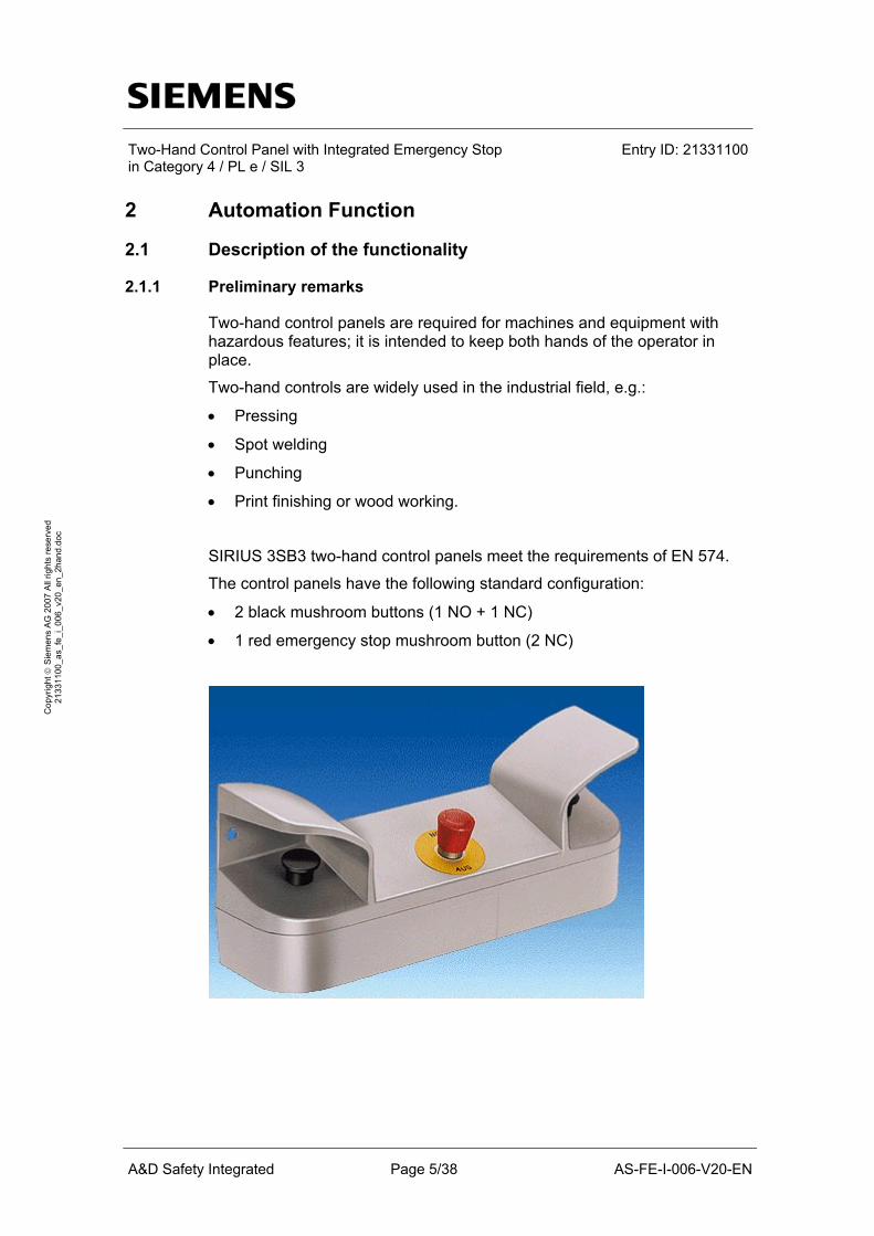
SIRIUS 3SB3 two-hand control panels meet the requirements of EN 574.
The control panels have the following standard configuration:
• 2 black mushroom buttons (1 NO + 1 NC)
• 1 red emergency stop mushroom button (2 NC)

Two-Hand Control Panel with Integrated Emergency Stop in Category 4 / PL e / SIL 3
Entry ID: 21331100
A&D Safety Integrated Page 6/38 AS-FE-I-006-V20-EN
Cop
yrig
ht ©
Sie
men
s A
G 2
007
All
right
s re
serv
ed
2133
1100
_as_
fe_i
_006
_v20
_en_
2han
d.do
c
The relevant standards for the two-hand control panel are listed below:
Standard Content
EN 574: 1996 Safety of machinery – Two-hand control devices EN ISO 13850: 2006 Safety of machinery – Emergency stop equipment EN 999: 1998 Approach speeds EN ISO 12100-1: 2003 Safety of machinery – General principles of design EN 60204-1: 2006 Safety of machinery – Electrical equipment of machines EN 60947-5-1: 2004 Low-voltage switching devices – Positive opening
operation EN 954-1: 1996 Safety of machinery – Safety-related parts of control
systems EN ISO 13849-1: 2006 Safety of machinery – Safety-related parts of control
systems – Part 1: General design rules EN 62061: 2005 Safety of machinery - Functional safety of safety-
relevant electrical, electronic and programmable electronic control systems.
2.1.2 Functionality of the safety functional example
A characteristic feature of the two-hand control is the fact that both hands are kept in one place. The desired actions can only be started if both mushroom buttons of the two-hand control panel are pressed. Each of the two mushroom buttons is an exclusive OR sensor (normally open (NO) contact and normally closed (NC) contact).
NO contact and NC contact of the exclusive OR sensor have to switch within a discrepancy time when operated. The length of this discrepancy time is parameterized in the hardware configuration of STEP 7 max. 500 ms according to EN 574).

Two-Hand Control Panel with Integrated Emergency Stop in Category 4 / PL e / SIL 3
Entry ID: 21331100
A&D Safety Integrated Page 7/38 AS-FE-I-006-V20-EN
Cop
yrig
ht ©
Sie
men
s A
G 2
007
All
right
s re
serv
ed
2133
1100
_as_
fe_i
_006
_v20
_en_
2han
d.do
c
Besides the discrepancy time monitoring between NO contact and NC contact of an exclusive OR sensor, the switching times between exclusive OR sensor 1 and 2 are monitored. This discrepancy time monitoring is parameterized in the safety program of STEP 7 at the F application block. When actuating both exclusive OR sensors, an application starts which is active for 4 seconds. After that time, or if at least one of the exclusive OR sensors is released, the machine shuts down automatically. Restarting the application is only possible if both exclusive OR sensors are released and actuated again.
In the safety functional example, the application is simulated by an indicator light (actuator) connected to a failsafe digital output module of the ET 200S I/O system. An application can be a hazardous machine, for instance. The term "machine" will be used to designate the indicator light (actuator) in the following.
NOTICE In order to meet the requirements of Category 4 / PL e / SIL 3, it is obligatory to read back the process signal to certain actuators (e.g. contactor). Read-back is not implemented in this Safety Functional Example. The actuator is an indicator light simulating a machine. When using different actuators, the feedback circuits have to be integrated and evaluated by the user. Safety Functional Example 7 provides a detailed description of “Read back”.
Emergency stop Pressing the emergency stop push button resets the indicator light (simulated stop of the "machine"). Prior to a restart of the "machine" start it is required to unlock and acknowledge the emergency stop push button.
Acknowledgement An acknowledgement is necessary in the following cases:
• before starting the "machine" for the first time
• after unlocking the emergency stop button
• after exceeding the discrepancy time of an exclusive OR sensor
• after reintegrating (end of passivation) the F-DI
Response time Use the Excel file, which is available for S7 Distributed Safety V 5.4, to calculate the max. response time of your F system. This file is available on the internet: http://support.automation.siemens.com/WW/view/en/25412441

Two-Hand Control Panel with Integrated Emergency Stop in Category 4 / PL e / SIL 3
Entry ID: 21331100
A&D Safety Integrated Page 8/38 AS-FE-I-006-V20-EN
Cop
yrig
ht ©
Sie
men
s A
G 2
007
All
right
s re
serv
ed
2133
1100
_as_
fe_i
_006
_v20
_en_
2han
d.do
c
Flowchart The following flowchart illustrates the function process of the safety example.

Two-Hand Control Panel with Integrated Emergency Stop in Category 4 / PL e / SIL 3
Entry ID: 21331100
A&D Safety Integrated Page 9/38 AS-FE-I-006-V20-EN
Cop
yrig
ht ©
Sie
men
s A
G 2
007
All
right
s re
serv
ed
2133
1100
_as_
fe_i
_006
_v20
_en_
2han
d.do
c
Time sequence The illustration below shows the time relations:
The above times are explained in the following table.
Time Explanation Note
∆t1 Discrepancy time between make contact and break contact at exclusive OR sensor 1
∆t2 Discrepancy time between make contact and break contact at exclusive OR sensor 2
Parameterized in the hardware configuration of STEP 7.
∆t3 Discrepancy time between exclusive OR sensor 1 and 2
Programmed in the safety program of STEP 7.
t1 Start of the “machine” Simulated by switching on the indicator light. t2 Stop of the “machine” Simulated by switching off the indicator light.
Possible reasons for the stop: • End of “machine run time” • At least one exclusive OR sensor was
released • Emergency stop was actuated • Passivation of the failsafe input module
of ET 200S (F-DI)

Two-Hand Control Panel with Integrated Emergency Stop in Category 4 / PL e / SIL 3
Entry ID: 21331100
A&D Safety Integrated Page 10/38 AS-FE-I-006-V20-EN
Cop
yrig
ht ©
Sie
men
s A
G 2
007
All
right
s re
serv
ed
2133
1100
_as_
fe_i
_006
_v20
_en_
2han
d.do
c
2.2 Advantage / Customer benefits
SIMATIC Safety Integrated
• Wiring reduced to a minimum due to use of fail-safe S7-CPU and distributed I/O. The more safety functions are implemented, the more useful this advantage is.
• Programming the fail-safe program with STEP7 engineering tools.
• Only one S7-CPU is required, since within the S7-CPU fail-safe and standard program parts run on a coexistent basis.
• Use of prefabricated and certified failsafe blocks from the S7 Distributed Safety library (F application blocks).
SIRIUS two-hand control panel • Design of the two-hand control with integrated control devices including
emergency stop
• Additional control devices can be mounted
• Two-hand control panel in metal design for harsh industrial environment
• Compliance with all relevant standards
Two-Hand Control Panel with Integrated Emergency Stop in Category 4 / PL e / SIL 3
Entry ID: 21331100
A&D Safety Integrated Page 11/38 AS-FE-I-006-V20-EN
Cop
yrig
ht ©
Sie
men
s A
G 2
007
All
right
s re
serv
ed
2133
1100
_as_
fe_i
_006
_v20
_en_
2han
d.do
c
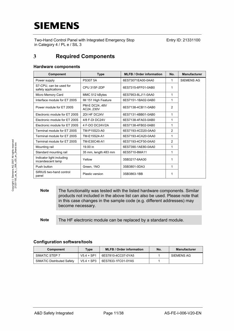
3 Required Components
Hardware components
Component Type MLFB / Order information No. Manufacturer Power supply PS307 5A 6ES73071EA00-0AA0 1
S7-CPU, can be used for safety applications CPU 315F-2DP 6ES7315-6FF01-0AB0 1
Micro Memory Card MMC 512 kBytes 6ES7953-8LJ11-0AA0 1
Interface module for ET 200S IM 151 High Feature 6ES7151-1BA02-0AB0 1
Power module for ET 200S PM-E DC24..48V AC24..230V 6ES7138-4CB11-0AB0 2
Electronic module for ET 200S 2DI HF DC24V 6ES7131-4BB01-0AB0 1
Electronic module for ET 200S 4/8 F-DI DC24V 6ES7138-4FA03-0AB0 1
Electronic module for ET 200S 4 F-DO DC24V/2A 6ES7138-4FB02-0AB0 1
Terminal module for ET 200S TM-P15S23-A0 6ES7193-4CD20-0AA0 2
Terminal module for ET 200S TM-E15S24-A1 6ES7193-4CA20-0AA0 1
Terminal module for ET 200S TM-E30C46-A1 6ES7193-4CF50-0AA0 2
Mounting rail 19.00 in 6ES7390-1AE80-0AA0 1
Standard mounting rail 35 mm, length:483 mm 6ES5710-8MA11 1
Indicator light including incandescent lamp Yellow 3SB3217-6AA30 1
Push button Green, 1NO 3SB3801-0DA3 1
SIRIUS two-hand control panel Plastic version 3SB3863-1BB 1
SIEMENS AG
Note The functionality was tested with the listed hardware components. Similar products not included in the above list can also be used. Please note that in this case changes in the sample code (e.g. different addresses) may become necessary.
Note The HF electronic module can be replaced by a standard module.
Configuration software/tools
Component Type MLFB / Order information No. Manufacturer SIMATIC STEP 7 V5.4 + SP1 6ES7810-4CC07-0YA5 1
SIMATIC Distributed Safety V5.4 + SP3 6ES7833-1FC01-0YA5 1
SIEMENS AG

Two-Hand Control Panel with Integrated Emergency Stop in Category 4 / PL e / SIL 3
Entry ID: 21331100
A&D Safety Integrated Page 12/38 AS-FE-I-006-V20-EN
Cop
yrig
ht ©
Sie
men
s A
G 2
007
All
right
s re
serv
ed
2133
1100
_as_
fe_i
_006
_v20
_en_
2han
d.do
c
4 Setup and Wiring
In order to set up and wire the safety functional example, it is absolutely necessary to consider the following note:
WARNING In order to meet the requirements of Category 4 / PL e / SIL 3, it is obligatory to read back the process signal to certain actuators (e.g. contactor). Read-back is not implemented in this Safety Functional Example. The actuator is an indicator light simulating a machine. When using different actuators, the feedback circuits have to be integrated and evaluated by the user. Safety Functional Example 7 provides a detailed description of “Read back”.
4.1 Overview of the hardware configuration
The arrangement to use a two-hand control panel consists of a configuration with PROFIBUS DP (with PROFIsafe profile). A fail-safe S7-CPU is used as DP master, an ET 200S as DP slave. The indicator light (simulated machine) can be replaced by actuators in accordance with their requirements.

Two-Hand Control Panel with Integrated Emergency Stop in Category 4 / PL e / SIL 3
Entry ID: 21331100
A&D Safety Integrated Page 13/38 AS-FE-I-006-V20-EN
Cop
yrig
ht ©
Sie
men
s A
G 2
007
All
right
s re
serv
ed
2133
1100
_as_
fe_i
_006
_v20
_en_
2han
d.do
c
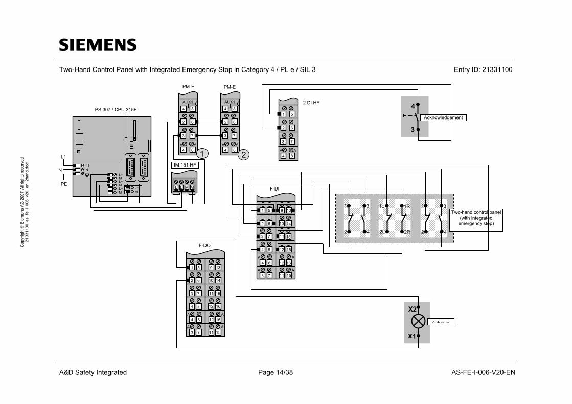
4.2 Wiring of hardware components
Requirements: The power supplies are supplied with 230V AC. First check the addresses set at the hardware components listed below:
Hardware component
Address to be set
Note
IM 151 HF 6 (PROFIBUS address) Can be changed. F-DI Switch position:
1111111110 F-DO Switch position:
1111111101
The PROFIsafe addresses are automatically assigned when configuring the fail-safe modules in STEP 7. The PROFIsafe addresses 1 to 1022 are permissible. Please make sure that the setting at the address switch (DIL switch) on the side of the module corresponds to the PROFIsafe address in the hardware configuration of STEP 7.
Note The DP interface of the CPU 315F must be connected with the DP
interface of the IM 151 HF.
Note The wiring of the hardware is illustrated below. In the following table, the
hardware components occurring several times are numbered. This ensures that they can be clearly assigned in the subsequent wiring diagram.
Two-Hand Control Panel with Integrated Emergency Stop in Category 4 / PL e / SIL 3 Entry ID: 21331100
A&D Safety Integrated Page 14/38 AS-FE-I-006-V20-EN
Cop
yrig
ht ©
Sie
men
s A
G 2
007
All
right
s re
serv
ed
2133
1100
_as_
fe_i
_006
_v20
_en_
2han
d.do
c
5 139
62 1410
73 1511
84 1612
84A
1612A
73A
1511A
F-DI
X2
X1
Actuator
51 139
62 1410
73 1511
84 1612
84A
1612A
73A
1511A
F-DO
4
3
Acknowledgement
1
2 4
3 1L
2L
1R
2R
1
2 4
3Two-hand control panel
(with integrated emergency stop)
L L M M
L1
N
PE
IM 151 HF
PS 307 / CPU 315F
PM-E
84
62
73
84A A
AUX1
1
84
62
73
84A A
AUX1
2
L+ M
L+ M L+ M L+ M
L1N
5 1
62
73
84A A
2 DI HF
1
PM-E

Two-Hand Control Panel with Integrated Emergency Stop in Category 4 / PL e / SIL 3
Entry ID: 21331100
A&D Safety Integrated Page 15/38 AS-FE-I-006-V20-EN
Cop
yrig
ht ©
Sie
men
s A
G 2
007
All
right
s re
serv
ed
2133
1100
_as_
fe_i
_006
_v20
_en_
2han
d.do
c
The wiring diagram shown above takes the following aspect into account:
Each of the two exclusive OR sensors of the two-hand control panel has to be connected in such a way that the first contact is a NO contact and the second contact is a NC contact. If the short circuit test of the failsafe input module (F-DI) is activated, both contacts of the exclusive OR sensor have to be supplied with voltage via the internal sensor supply VS1. Once a discrepancy between the signals of the two affected input channels is detected, the value “0” is made available to the safety program in the F CPU (parameterized in the hardware configuration of STEP 7).
4.3 Function test
The inputs and outputs used can be checked with regard to their functionality if the following conditions are met:
• the hardware components are wired
• the STEP 7 project was loaded into the S7-CPU
Inputs/outputs used
No. HW component Address Button Signal (default value)
Note
1 Push button (NO) E 0.0 ACK “0” Acknowledgement 2 Mushroom button 1
two-hand control panel (NO/NC)
E 1.0 HAND1 “0” The NO contact is evaluated
3 Mushroom button 2 two-hand control panel (NO/NC)
E 1.1 HAND2 “0“ The NO contact is evaluated
4 Emergency stop on two-hand control panel (NC/NC)
E 1.2 ESTP “1“ Activating the emergency stop
5 Actuator (indicator light)
A 7.0 LAMP “0” Simulates a hazardous machine “0“ signal: "Machine" is switched off

Two-Hand Control Panel with Integrated Emergency Stop in Category 4 / PL e / SIL 3
Entry ID: 21331100
A&D Safety Integrated Page 16/38 AS-FE-I-006-V20-EN
Cop
yrig
ht ©
Sie
men
s A
G 2
007
All
right
s re
serv
ed
2133
1100
_as_
fe_i
_006
_v20
_en_
2han
d.do
c
Testing inputs and outputs Requirements: The inputs and outputs have the default values specified under “Inputs/outputs used”.
Response No. Instructions
A 7.0
Note
1 Press the push button ACK and release it
“0“ Acknowledgement (the negative edge is evaluated)
2 Press and simultaneously hold the mushroom buttons 1 and 2 of the two-hand control panel.
“1“ Starting (switching on) the “machine”.
3 Wait 4 seconds “1“ -> “0“ Simulated machine run time 4 Release the mushroom buttons 1 and 2
of the two-hand control panel. “0“ New start of the “machine”
possible 5 Press and simultaneously hold the
mushroom buttons 1 and 2 of the two-hand control panel and release one mushroom button after approx. 1 sec.
“1“ -> “0“ “Machine” starts and stops
Note An acknowledgement is required after certain events. See section "Acknowledgement" in the chapter 2.

Two-Hand Control Panel with Integrated Emergency Stop in Category 4 / PL e / SIL 3
Entry ID: 21331100
A&D Safety Integrated Page 17/38 AS-FE-I-006-V20-EN
Cop
yrig
ht ©
Sie
men
s A
G 2
007
All
right
s re
serv
ed
2133
1100
_as_
fe_i
_006
_v20
_en_
2han
d.do
c
4.4 Important hardware component settings
The STEP 7 project delivered with this safety functional example contains the hardware configuration and the sample code.
Below, several important settings from the hardware configuration of STEP 7 are shown to provide you with an overview. It is basically possible to change these settings (e.g. due to individual requirements), but please consider the following note:
NOTICE The settings shown below contribute to meeting the requirements of Category 4 /PL e / SIL 3. Changes at the settings may cause loss of the safety function.
If you make changes to the hardware configuration of STEP 7 (e.g. add an additional module), the sample code of the delivered STEP 7 project must be adapted accordingly.
Overview picture
The PROFIBUS address at IM 151 HF is set using DIP switches.
Two-Hand Control Panel with Integrated Emergency Stop in Category 4 / PL e / SIL 3
Entry ID: 21331100
A&D Safety Integrated Page 18/38 AS-FE-I-006-V20-EN
Cop
yrig
ht ©
Sie
men
s A
G 2
007
All
right
s re
serv
ed
2133
1100
_as_
fe_i
_006
_v20
_en_
2han
d.do
c
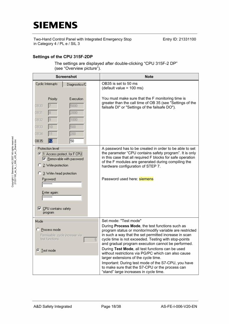
Settings of the CPU 315F-2DP The settings are displayed after double-clicking “CPU 315F-2 DP” (see “Overview picture”).
Screenshot Note
OB35 is set to 50 ms (default value = 100 ms) You must make sure that the F monitoring time is greater than the call time of OB 35 (see "Settings of the failsafe DI" or "Settings of the failsafe DO").
A password has to be created in order to be able to set the parameter “CPU contains safety program”. It is only in this case that all required F blocks for safe operation of the F modules are generated during compiling the hardware configuration of STEP 7. Password used here: siemens
Set mode: "Test mode" During Process Mode, the test functions such as program status or monitor/modify variable are restricted in such a way that the set permitted increase in scan cycle time is not exceeded. Testing with stop-points and gradual program execution cannot be performed. During Test Mode, all test functions can be used without restrictions via PG/PC which can also cause larger extensions of the cycle time. Important: During test mode of the S7-CPU, you have to make sure that the S7-CPU or the process can “stand” large increases in cycle time.

Two-Hand Control Panel with Integrated Emergency Stop in Category 4 / PL e / SIL 3
Entry ID: 21331100
A&D Safety Integrated Page 19/38 AS-FE-I-006-V20-EN
Cop
yrig
ht ©
Sie
men
s A
G 2
007
All
right
s re
serv
ed
2133
1100
_as_
fe_i
_006
_v20
_en_
2han
d.do
c
Settings of the failsafe DI (F-DI) The settings are displayed after double-clicking “4/8 F-DI DC24V”.
Screenshot Note
Parameters / F parameters: DIP switch setting (9…0) This value has to be set on the F module (F-DI). F-monitoring time (ms) The F-monitoring time must be larger than the call time of OB35.
Parameters / Module parameters: Category 4 / PL e / SIL 3 is reached by carrying out a cross-circuit detection. The cyclic short-circuit test and the sensor supply must be activated via the F module. Short-circuit test: The cyclic short-circuit test is activated (cross-circuit detection). Behavior after channel faults: The entire F module is passivated in the event of a channel fault. Parameters / Module parameters: Assignment of channels: Channel 0, 4: Exclusive OR sensor 1 Channel 1, 5: Exclusive OR sensor 2 Channel 2, 6: Emergency stop
Parameterization of the channels: Activated: Used channels are activated, unused channels are deactivated. Sensor supply: The internal sensor voltage is activated so that the short-circuit test can be carried out. Evaluation of the sensors: 1oo2 evaluation Type of sensor interconnection Channel 0, 4 and 1, 5: 2-channel antivalent Channel 2, 6: 2-channel equivalent Behavior at discrepancy: A safe "0" signal is provided at discrepancy. Discrepancy time (ms) Channel 0, 4 and channel 1, 5: Discrepancy time between the NO and the NC contact of an exclusive OR sensor. Channel 2, 6: Discrepancy time of emergency stop Reintegration after discrepancy: No test with "0" signal is required after elimination of the discrepancy fault.

Two-Hand Control Panel with Integrated Emergency Stop in Category 4 / PL e / SIL 3
Entry ID: 21331100
A&D Safety Integrated Page 20/38 AS-FE-I-006-V20-EN
Cop
yrig
ht ©
Sie
men
s A
G 2
007
All
right
s re
serv
ed
2133
1100
_as_
fe_i
_006
_v20
_en_
2han
d.do
c
Settings of the fail-safe DO (F-DO) The settings are displayed after double-clicking “4 F-DO DC24V/2A” (see “Overview picture”).
Screenshot Note
Parameters / F parameters: DIP switch setting (9…0) This value has to be set on the F module (F-DO). F-monitoring time (ms) The F-monitoring time must be larger than the call time of OB35. Parameters / Module parameters: Assignment of channels: DO channel 0: Channel 0 switches the indicator light
Parameterization of the channels: Behavior after channel faults The entire F module is passivated in the event of a channel fault. Activated Used channels are activated, unused channels are deactivated. Read-back time The read-back time defines the duration of the switch-off procedure for the channel. If the channel switches high capacity loads the read-back time should be set sufficiently. We recommend setting the read back time as small as possible, however large enough so that the channel does not become passive.

Two-Hand Control Panel with Integrated Emergency Stop in Category 4 / PL e / SIL 3
Entry ID: 21331100
A&D Safety Integrated Page 21/38 AS-FE-I-006-V20-EN
Cop
yrig
ht ©
Sie
men
s A
G 2
007
All
right
s re
serv
ed
2133
1100
_as_
fe_i
_006
_v20
_en_
2han
d.do
c
5 Basic Performance Data
Load memory and main memory
Total Portion of S7 standard blocks Portion of F blocks
Load Memory 53.1 Kbytes 0.9 Kbytes 52.2 Kbytes Main Memory 38.2 Kbytes 0.3 Kbytes 37.9 Kbytes
Cycle time
Time Note
Typical total cycle time (standard program and safety program)
Approx. 2 ms
Measurement in the S7-CPU ("Module information CPU" / "Cycle time")
Maximum runtime safety program
9 ms Calculation using an Excel file available for S7 Distributed Safety Chapter 1 tells you where on the internet you can find the table.
6 Sample Code
6.1 Download
Preliminary remark The STEP 7 project delivered with this safety functional example contains the hardware configuration and the sample code. The sample code is described in the following. The sample code is always assigned to the components used in the safety functional example and implements the required functionality. Problems not dealt with in this document are to be realized by the user; the sample code may serve as a basis. The sample code provides measures for fault detection (diagnostics). The user has to evaluate this information and the fault must be responded to (second shut-down method, ...).
Note A connection between the MPI interface of your PG/PC and the MPI interface of the CPU 315F-2DP (MPI cable) is required to download the STEP7 project into the CPU 315F-2DP.
Password In all cases, the password used for the safety-relevant part of the sample code is: siemens

Two-Hand Control Panel with Integrated Emergency Stop in Category 4 / PL e / SIL 3
Entry ID: 21331100
A&D Safety Integrated Page 22/38 AS-FE-I-006-V20-EN
Cop
yrig
ht ©
Sie
men
s A
G 2
007
All
right
s re
serv
ed
2133
1100
_as_
fe_i
_006
_v20
_en_
2han
d.do
c
Use of the STEP7 project The STEP 7 project shows:
• connection of a SIRIUS two-hand control panel with integrated emergency stop to failsafe modules of the ET 200S (F-DI, F-DO)
• evaluation using a failsafe S7-CPU (F_CPU)
The conditions necessary for the actuators to meet the requirements of Category 4 / PL e / SIL 3 (e.g. read back of the actuator signals) are not considered.
Functionality of the STEP 7 project The following functions are implemented with the STEP 7 project:
• With the two-hand control panel a “machine” is started, which is simulated by an indicator light in this example.
• As soon as one mushroom button is released or if the simulated “machine run time” has elapsed, the “machine” stops (indicator light goes off).
• Furthermore, the “machine” stops if the failsafe input/output modules of the ET 200S are passivated and if the emergency stop push push button integrated in the two-hand control panel is actuated.
Download On the HTML page of the safety functional example, you will find the following file containing the STEP 7 project with the downloads:
• 21331100_as_fe_i_004_v20_code_2hand.zip Save this file to any directory on your PC / PG. Start STEP 7 and extract the file into any directory. To load the STEP 7 project into the S7-CPU, proceed as follows:
• First load the hardware configuration into the S7-CPU
• Switch to the SIMATIC Manager.
• Select the S7-CPU.
• Go to the "Options" menu and select: "Edit safety program"
• Click the "Download" button to load the sample code in to the S7-CPU.

Two-Hand Control Panel with Integrated Emergency Stop in Category 4 / PL e / SIL 3
Entry ID: 21331100
A&D Safety Integrated Page 23/38 AS-FE-I-006-V20-EN
Cop
yrig
ht ©
Sie
men
s A
G 2
007
All
right
s re
serv
ed
2133
1100
_as_
fe_i
_006
_v20
_en_
2han
d.do
c
6.2 Program execution standard program
The standard program only consists of a call of FC F-CALL in the cyclic interrupt OB (OB35). The only signal not safety-related (acknowledgement signal) is evaluated directly in the safety program.
6.3 Program execution safety program
Structure The safety program has the following structure:
F-CALL (FC1) F-CALL (FC1) is the F runtime group and it is called from the cyclic interrupt OB (OB35).
F-CALL calls the F program block (here: FC2).

Two-Hand Control Panel with Integrated Emergency Stop in Category 4 / PL e / SIL 3
Entry ID: 21331100
A&D Safety Integrated Page 24/38 AS-FE-I-006-V20-EN
Cop
yrig
ht ©
Sie
men
s A
G 2
007
All
right
s re
serv
ed
2133
1100
_as_
fe_i
_006
_v20
_en_
2han
d.do
c
FB 2H_and_ESTP (FC2) For modularity reasons of the program, all further failsafe blocks are called from here.
The "two-hand control" functionality is basically implemented by the following blocks called in the FC2:
Block Task
FC 2Hand (FC3) Evaluation of the status of the two exclusive OR sensors of the two-hand control panel.
FC E_STOP (FC4) Evaluation of the emergency stop push button integrated in the two-hand control panel
FC START (FC5) Evaluation of the information from FC3 and FC4 to start the “machine”.
FC REINTEGRATION (FC6) Reintegration after passivation of F-DI or F-DO.
Network 1 Here the FC 2Hand (FC3) is called:
The following table explains the parameters of the block:
Parameter Assignment Function
HAND1 Exclusive OR sensor 1 of the two-hand control panel
HAND2 Exclusive OR sensor 2 of the two-hand control panel
Starting the “machine”. To start the machine, both exclusive OR sensors must be pressed simultaneously and have to remain pressed during the entire “machine time”.
HELP_DB1.COND1 Bit from F data block Storing the result for later evaluation in FC5
The FC3 calls the FB F_2H_EN (FB211, DB 211). FB211 is described further below.

Two-Hand Control Panel with Integrated Emergency Stop in Category 4 / PL e / SIL 3
Entry ID: 21331100
A&D Safety Integrated Page 25/38 AS-FE-I-006-V20-EN
Cop
yrig
ht ©
Sie
men
s A
G 2
007
All
right
s re
serv
ed
2133
1100
_as_
fe_i
_006
_v20
_en_
2han
d.do
c
Network 2 Here the FC E_STOP (FC4) is called.
The following table explains the parameters of the block.
Parameter Assignment Function
ACK Push button (NO) An acknowledgement prior to the start of the “machine” is required in the following cases: • prior to the first start • after unlocking the emergency stop • after exceeding the discrepancy time of
an exclusive OR sensor • after reintegrating (end of passivation)
the F-DI The ACK signal is received by a standard DI.
ESTP Emergency stop push button (NC/NC)
Interruption of the “machine activity”
HELP_DB1.COND2 Bit from F data block Storing the result for later evaluation in FC5
Network 3 Here the FC START (FC5) is called.

Two-Hand Control Panel with Integrated Emergency Stop in Category 4 / PL e / SIL 3
Entry ID: 21331100
A&D Safety Integrated Page 26/38 AS-FE-I-006-V20-EN
Cop
yrig
ht ©
Sie
men
s A
G 2
007
All
right
s re
serv
ed
2133
1100
_as_
fe_i
_006
_v20
_en_
2han
d.do
c
The following table explains the parameters of the block:
Parameter Assignment Function
HELP_DB1.COND1 Bit from F data block Condition for the start of the “machine” from FC3
HELP_DB1.COND2 Bit from F data block Condition for the start of the “machine” from FC4
LAMP Indicator light connected to the F-DO
Simulates the “machine” to be started by the two-hand control.
To start the “machine” (indicator light ON), the two bits HELP_DB1.COND1 and HELP_DB1.COND2 must each have a “1” signal.
The “machine” will then run for 4 seconds (LAMP="1"). Subsequently the “machine” stops (LAMP=“0”). To restart the machine, the mushroom buttons of the two-hand control have to be released once.
The machine time is simulated with FB F_TON (FB185). FB F_TON (FB185) is a certified block from the Distributed Safety library (F application block).
Network 4 Here the FC REINTEGRATION (FC6) is called. FC6 is described further below.

Two-Hand Control Panel with Integrated Emergency Stop in Category 4 / PL e / SIL 3
Entry ID: 21331100
A&D Safety Integrated Page 27/38 AS-FE-I-006-V20-EN
Cop
yrig
ht ©
Sie
men
s A
G 2
007
All
right
s re
serv
ed
2133
1100
_as_
fe_i
_006
_v20
_en_
2han
d.do
c
FB F_2H_EN (FB211, DB 211) FB211 is a certified block from the Distributed Safety library (F application block).
In #HAND1 and #HAND2, the NO contacts of the exclusive OR sensors of the two-hand control panel are polled.
Both exclusive OR sensors have to be pressed within a certain time. This time is entered at the DISCTIME parameter of FB211. The highest setting allowed for this parameter is 500 ms (according to EN 574).
Only if the signal at the ENABLE input is "1", can Q become "1". The bit "HELP_DB1“.EN_ESTP" evaluates the emergency stop signal (from FC4):
• HELP_DB1“.EN_ESTP is "1" when the emergency stop push button was unlocked again and subsequently acknowledged after being triggered.
By applying "HELP_DB1".EN_ESTP to ENABLE, the following behavior is taken into account: The two exclusive OR sensors of the two-hand control panel are pressed and remain depressed during the following conditions:
• The emergency stop push button is applied.
• The emergency stop push button is unlocked.
• An acknowledgement is carried out.
Applying bit "HELP_DB1".EN_ESTP to ENABLE prevents a direct starting of the "machine" under the conditions described above. Before it can be started again, both exclusive OR sensors of the two-hand control panel must be released and then pressed again simultaneously.
Note The bits from the data block HELP_DB1 (DB1) mentioned above and used in the sample code are only used for buffering.

Two-Hand Control Panel with Integrated Emergency Stop in Category 4 / PL e / SIL 3
Entry ID: 21331100
A&D Safety Integrated Page 28/38 AS-FE-I-006-V20-EN
Cop
yrig
ht ©
Sie
men
s A
G 2
007
All
right
s re
serv
ed
2133
1100
_as_
fe_i
_006
_v20
_en_
2han
d.do
c
FC REINTEGRATION (FC6) The reintegration is implemented in FC6 for passivation of the F-DI or F-DO. The memory bit #REINT is prepared for the F-DO. The F-DO is reintegrated with a positive edge at the memory bit #REINT.
! WARNING
In this safety functional example, passivated F modules are integrated automatically. Use the automatic reintegration for your application only if it will not cause any hazards.
A passivation is indicated by an illuminated LED “SF” on the F module. The reintegration of an F module may take about one minute.
6.4 Operating instructions
Prerequisite:
• Hardware configuration and sample code of the STEP 7 project are available in the S7-CPU
• Emergency stop is unlocked
• No passivation of the F-DI and the F-DO
The table below demonstrate the function principle:
No. Instructions Result / Note
1 Press the push button ACK and release it
required before starting the "machine" for the first time
2 Simultaneously press the two exclusive OR sensors of the two-hand control panel and keep them pressed
Start of the “machine” (indicator light goes on)
3 Wait 4 seconds Simulated machine run time: After 4 seconds the “machine” goes off (indicator light goes off).
4 Release both exclusive OR sensors of the two-hand control panel
You can now continue with no. 2.
Note An acknowledgement is required after certain events. See section "Acknowledgement" in chapter 2.

Two-Hand Control Panel with Integrated Emergency Stop in Category 4 / PL e / SIL 3
Entry ID: 21331100
A&D Safety Integrated Page 29/38 AS-FE-I-006-V20-EN
Cop
yrig
ht ©
Sie
men
s A
G 2
007
All
right
s re
serv
ed
2133
1100
_as_
fe_i
_006
_v20
_en_
2han
d.do
c
7 Evaluation acc. to EN 62061 and EN ISO 13849-1: 2006
7.1 Information about the standards
The following safety functional example gives an overview of EN 62061:
• http://support.automation.siemens.com/WW/view/en/23996473 The following book gives an overview of ISO 13849:
• Funktionale Sicherheit von Maschinen und Anlagen. Umsetzung der europäischen Maschinenrichtlinie in der Praxis. (ISBN-13: 978-3-89578-281-7, ISBN-10: 3-89578-281-5)
7.2 Safety function
Two safety functions are implemented by means of the two-hand control panel:
• the "normal" safety function SF1
• the "supplementary" safety function SF2
safety function SF1 The "machine" can only be switched on if both mushroom
buttons are actuated simultaneously. Supplementary safety function
SF2 If the emergency stop is actuated, the “machine” must be switched off.
This safety function examples does not deal with the entire safety function; it focuses on certain tasks only:
Tasks Safety function
Detect Evaluate React
SF1 x x SF2 x x
not considered (*1)
Explanations on the above the table:
(*x) Explanation
(*1) See safety functional example no. 7 (entry ID: 21331098): Integration of the readback signal into an application in category 4 according to EN 954-1: 1996
The two tasks mentioned above will be evaluated on the basis of the two standards EN 62061 and EN ISO 13849-1: 2006.

Two-Hand Control Panel with Integrated Emergency Stop in Category 4 / PL e / SIL 3
Entry ID: 21331100
A&D Safety Integrated Page 30/38 AS-FE-I-006-V20-EN
Cop
yrig
ht ©
Sie
men
s A
G 2
007
All
right
s re
serv
ed
2133
1100
_as_
fe_i
_006
_v20
_en_
2han
d.do
c
8 Safety Function 1
8.1 Mapping the safety function
The following illustration shows the mapping of the safety function to the safety functional example:
„Evaluate“
„Detect“ (without Emergency Stop)
„React“ Is not considered

Two-Hand Control Panel with Integrated Emergency Stop in Category 4 / PL e / SIL 3
Entry ID: 21331100
A&D Safety Integrated Page 31/38 AS-FE-I-006-V20-EN
Cop
yrig
ht ©
Sie
men
s A
G 2
007
All
right
s re
serv
ed
2133
1100
_as_
fe_i
_006
_v20
_en_
2han
d.do
c
8.2 Assessment of "Detect"
8.2.1 Evaluation according to EN 62061
Results:
Result Explanation
SILCL 3 Hardware fault tolerance: HFT = 1
Safe failure fraction: SFF ≥ 0.99 (99%)
PFHD 2.4 * 10-9 Architecture: Basic subsystem architecture D, with identical subsystem elements
The values for the calculation can be found in the following table.
Values for calculating the PFHD:
Parameter Value Explanation Definition
B10 B10 value exclusive OR sensor
1 * 107 Manufacturer information
Dangerous failure fraction exclusive OR sensor
0.2 (20%) Manufacturer information
T1 Lifetime
175,200 h (20 years)
expected lifetime
SIEMENS AG
C Number of actuations exlusive OR sensor
12 / h Assumptions: An actuation takes place once every five minutes. Actuations take place on all days of the year (365 days).
T2 Diagnostic test interval
0.083 h A defective exclusive OR sensor is detected in the F-CPU after the actuation. (see „C“).
β (CCF factor) Susceptibility to common cause failures
0.1 (10%) In installations acc. to EN 62061, a CCF factor of 0.1 (10%) is achieved. This is a safe value ("conservative value").
DC Diagnostic coverage
≥ 0.99 (99%) Exclusive OR evaluation in F-DI, and cross-comparison in F-CPU.
Users

Two-Hand Control Panel with Integrated Emergency Stop in Category 4 / PL e / SIL 3
Entry ID: 21331100
A&D Safety Integrated Page 32/38 AS-FE-I-006-V20-EN
Cop
yrig
ht ©
Sie
men
s A
G 2
007
All
right
s re
serv
ed
2133
1100
_as_
fe_i
_006
_v20
_en_
2han
d.do
c
8.2.2 Evaluation according to EN ISO 13849-1: 2006
Results:
Result Explanation
PL e The values for the calculation can be found in the following table.
From Appendix K of EN ISO 13849-1: 2006.
Note: The MTTFd for each channel is limited to a maximum of 100 years!
Average probability of a hazardous failure
per hour
2.47 * 10-8
Note: For a more accurate result, we recommend the consideration according to EN 62061.
Values for determining PL:
Parameter Value Explanation
MTTFd
of each channel high
MTTFd ≥ 30 years The values for the calculation can be found in the following table.
DC high
DC = 99% Exclusive OR evaluation in F-DI, and cross-comparison in F-CPU
Measures against CCF
met It is assumed that the user takes the necessary measures.
Category 4 System behavior: An individual fault does not cause loss of the safety function. The individual fault is recognized. MTTFd: high, DC: high, measures against CCF: met
Values for calculating the MTTFd of each channel:
Parameter Value Explanation Definition
B10 B10 value exclusive OR sensor
1 * 107 Manufacturer information
Dangerous failure fraction exclusive OR sensor
0.2 (20%) Manufacturer information
SIEMENS AG
dop Average operating time per year in days
365 days per year
hop Average operating time per day in hours
24 hours per day
Assumption: Actuations take place on all days of the year.
tcycle Average time between the start of two subsequent cycles of the component
0.083 hours per cycle
Assumption: An interval of 5 minutes lies between the actuations of the exclusive OR sensor.
Users

Two-Hand Control Panel with Integrated Emergency Stop in Category 4 / PL e / SIL 3
Entry ID: 21331100
A&D Safety Integrated Page 33/38 AS-FE-I-006-V20-EN
Cop
yrig
ht ©
Sie
men
s A
G 2
007
All
right
s re
serv
ed
2133
1100
_as_
fe_i
_006
_v20
_en_
2han
d.do
c
8.3 Assessment of "Evaluate"
8.3.1 Evaluation according to EN 62061
Results:
Result Explanation
SILCL 3 Information of the manufacturer SIEMENS AG
PFHD 1.7 * 10-9 The values for the calculation can be found in the following table.
Values for calculating the PFHD:
Parameter Component Value Definition
PFHD (F-CPU) CPU 315F-2DP 5.42 * 10-10
F-DI of the ET200S 1 * 10-10 PFHD (F-I/O-module)
F-DO of the ET200S 1 * 10-10
PTE (F communication) F Communication:
F-CPU and ET200S 1 * 10-9
SIEMENS AG
8.3.2 Evaluation according to EN ISO 13849-1: 2006
Results:
Result Explanation
PL e
Average probability of a hazardous failure per hour
1.7 * 10-9
Derived from the evaluation acc. to IEC 61508.
8.4 Summary
The table shows the result of the evaluation according to the two standards:
EN 62061 EN ISO 13849-1: 2006 SILCL PFHD PL Average probability of a hazardous
failure per hour
Detect 3 2.4 * 10-9 e 2.47 * 10-8
Evaluate 3 1.7 * 10-9 e 1.7 * 10-9
React not considered
Two-Hand Control Panel with Integrated Emergency Stop in Category 4 / PL e / SIL 3
Entry ID: 21331100
A&D Safety Integrated Page 34/38 AS-FE-I-006-V20-EN
Cop
yrig
ht ©
Sie
men
s A
G 2
007
All
right
s re
serv
ed
2133
1100
_as_
fe_i
_006
_v20
_en_
2han
d.do
c
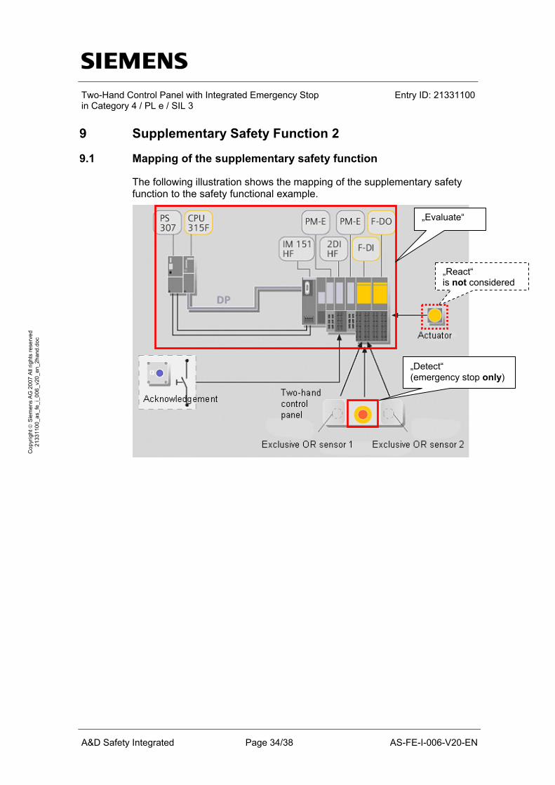
9 Supplementary Safety Function 2
9.1 Mapping of the supplementary safety function
The following illustration shows the mapping of the supplementary safety function to the safety functional example.
„Evaluate“
„Detect“ (emergency stop only)
„React“ is not considered

Two-Hand Control Panel with Integrated Emergency Stop in Category 4 / PL e / SIL 3
Entry ID: 21331100
A&D Safety Integrated Page 35/38 AS-FE-I-006-V20-EN
Cop
yrig
ht ©
Sie
men
s A
G 2
007
All
right
s re
serv
ed
2133
1100
_as_
fe_i
_006
_v20
_en_
2han
d.do
c
9.2 Assessment of "Detect"
9.2.1 Evaluation according to EN 62061
Results:
Result Explanation
SILCL 3 Hardware fault tolerance: HFT = 1 Safe failure fraction: SFF ≥ 0.99 (99%)
PFHD 1.2 * 10-10 Architecture: Basic subsystem architecture D, with identical subsystem elements
The values for the calculation can be found in the following table.
Values for calculating the PFHD:
Parameter Value Explanation Definition
B10 B10 value Emergency stop control unit
1 * 105 Manufacturer information
Dangerous failure fraction Emergency-stop control unit
0.2 (20%) Manufacturer information
T1 Lifetime
175,200 h (20 years)
expected lifetime
SIEMENS AG
C Number of actuation Emergency stop control unit
6 * 10-3 / h Assumptions: An actuation takes places every week (7 * 24 hours) (test emergency stop) Actuations can take place on all days of the year (365 days).
T2 Diagnostic test interval
168 h When actuating the emergency stop, a defective contact is detected in the F-DI. An actuation takes place every week (7 * 24 hours) (see "C").
β (CCF factor) Susceptibility to common cause failures
0.1 (10%) In installations acc. to EN 62061, a CCF factor of 0.1 (10%) is achieved. This is a safe value ("conservative value").
DC Diagnostic coverage
≥ 0.99 (99%) Cross-comparison F-DI
Users
Two-Hand Control Panel with Integrated Emergency Stop in Category 4 / PL e / SIL 3
Entry ID: 21331100
A&D Safety Integrated Page 36/38 AS-FE-I-006-V20-EN
Cop
yrig
ht ©
Sie
men
s A
G 2
007
All
right
s re
serv
ed
2133
1100
_as_
fe_i
_006
_v20
_en_
2han
d.do
c
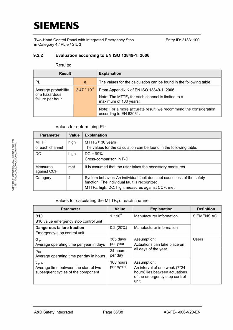
9.2.2 Evaluation according to EN ISO 13849-1: 2006
Results:
Result Explanation
PL e The values for the calculation can be found in the following table.
From Appendix K of EN ISO 13849-1: 2006.
Note: The MTTFd for each channel is limited to a maximum of 100 years!
Average probability of a hazardous failure per hour
2.47 * 10-8
Note: For a more accurate result, we recommend the consideration according to EN 62061.
Values for determining PL:
Parameter Value Explanation
MTTFd
of each channel high MTTFd ≥ 30 years
The values for the calculation can be found in the following table. DC high
DC = 99% Cross-comparison in F-DI
Measures against CCF
met It is assumed that the user takes the necessary measures.
Category 4 System behavior: An individual fault does not cause loss of the safety function. The individual fault is recognized. MTTFd: high, DC: high, measures against CCF: met
Values for calculating the MTTFd of each channel:
Parameter Value Explanation Definition
B10 B10 value emergency stop control unit
1 * 105 Manufacturer information
Dangerous failure fraction Emergency-stop control unit
0.2 (20%) Manufacturer information
SIEMENS AG
dop Average operating time per year in days
365 days per year
hop Average operating time per day in hours
24 hours per day
Assumption: Actuations can take place on all days of the year.
tcycle Average time between the start of two subsequent cycles of the component
168 hours per cycle
Assumption: An interval of one week (7*24 hours) lies between actuations of the emergency stop control unit.
Users

Two-Hand Control Panel with Integrated Emergency Stop in Category 4 / PL e / SIL 3
Entry ID: 21331100
A&D Safety Integrated Page 37/38 AS-FE-I-006-V20-EN
Cop
yrig
ht ©
Sie
men
s A
G 2
007
All
right
s re
serv
ed
2133
1100
_as_
fe_i
_006
_v20
_en_
2han
d.do
c
9.3 Assessment of "Evaluate"
9.3.1 Evaluation according to EN 62061
Results:
Result Explanation
SILCL 3 Information of the manufacturer SIEMENS AG
PFHD 1.7 * 10-9 The values for the calculation can be found in the following table.
Values for calculating the PFHD:
Parameter Component Value Definition
PFHD (F-CPU) CPU 315F-2DP 5,42 * 10-10
F-DI of the ET200S 1 * 10-10 PFHD (F-I/O-module)
F-DO of the ET200S 1 * 10-10
PTE (F communication) F Communication:
F-CPU and ET200S 1 * 10-9
SIEMENS AG
9.3.2 Evaluation according to EN ISO 13849-1: 2006
Results:
Result Explanation
PL e
Average probability of a hazardous failure per hour
1.7 * 10-9
Derived from the evaluation acc. to IEC 61508.
9.4 Summary
The table shows the result of the evaluation according to the two standards:
EN 62061 EN ISO 13849-1: 2006 SILCL PFHD PL Average probability of a hazardous
failure per hour
Detect 3 1.2 * 10-10 e 2.47 * 10-8
Evaluate 3 1.7 * 10-9 e 1.7 * 10-9
React not considered

Two-Hand Control Panel with Integrated Emergency Stop in Category 4 / PL e / SIL 3
Entry ID: 21331100
A&D Safety Integrated Page 38/38 AS-FE-I-006-V20-EN
Cop
yrig
ht ©
Sie
men
s A
G 2
007
All
right
s re
serv
ed
2133
1100
_as_
fe_i
_006
_v20
_en_
2han
d.do
c
10 History
Version Data Differences
V1.0 02 / 2005 First edition Updating the contents regarding: • Hardware and software • Performance data • Screenshots
V2.0 09 / 2007
New chapters: • Evaluation of the safety functional example according to the new
standards EN 62061 and EN ISO 13849-1: 2006