Synchronization made easy! February 2009 Preferred Synchronization methods.

SIMATIC PCS 7 time synchronization
____________________________
__________________________________________
Preface
Fundamentals 1
Configurations for time synchronization of a PCS 7 plant
2
Planning time synchronization
3Configuring time synchronization
4
Appendix A A
SIMATIC
Process Control System PCS 7PCS 7 time synchronization
Function Manual
01/2008 A5E01216578-01
Safety Guidelines Safety Guidelines This manual contains notices you have to observe in order to ensure your personal safety, as well as to prevent damage to property. The notices referring to your personal safety are highlighted in the manual by a safety alert symbol, notices referring only to property damage have no safety alert symbol. These notices shown below are graded according to the degree of danger.
DANGER indicates that death or severe personal injury will result if proper precautions are not taken.
WARNING indicates that death or severe personal injury may result if proper precautions are not taken.
CAUTION with a safety alert symbol, indicates that minor personal injury can result if proper precautions are not taken.
CAUTION without a safety alert symbol, indicates that property damage can result if proper precautions are not taken.
NOTICE indicates that an unintended result or situation can occur if the corresponding information is not taken into account.
If more than one degree of danger is present, the warning notice representing the highest degree of danger will be used. A notice warning of injury to persons with a safety alert symbol may also include a warning relating to property damage.
Qualified Personnel The device/system may only be set up and used in conjunction with this documentation. Commissioning and operation of a device/system may only be performed by qualified personnel. Within the context of the safety notes in this documentation qualified persons are defined as persons who are authorized to commission, ground and label devices, systems and circuits in accordance with established safety practices and standards.
Prescribed Usage Note the following:
WARNING This device may only be used for the applications described in the catalog or the technical description and only in connection with devices or components from other manufacturers which have been approved or recommended by Siemens. Correct, reliable operation of the product requires proper transport, storage, positioning and assembly as well as careful operation and maintenance.
Trademarks All names identified by ® are registered trademarks of the Siemens AG. The remaining trademarks in this publication may be trademarks whose use by third parties for their own purposes could violate the rights of the owner.
Disclaimer of Liability We have reviewed the contents of this publication to ensure consistency with the hardware and software described. Since variance cannot be precluded entirely, we cannot guarantee full consistency. However, the information in this publication is reviewed regularly and any necessary corrections are included in subsequent editions.
Siemens AG Automation and Drives Postfach 48 48 90327 NÜRNBERG GERMANY
A5E01216578-01 Ⓟ 02/2008
Copyright © Siemens AG 2008. Technical data subject to change

PCS 7 time synchronization Function Manual, 01/2008, A5E01216578-01 3
Preface
Purpose of this documentation The time synchronization documentation provides support for the following tasks of the "time synchronization" function in a PCS 7 system. ● Sales ● Planning ● Configuration It contains information for responding to the following questions: ● How does time synchronization function in a PCS 7 plant? ● How is time synchronization planned? ● How is time synchronization configured?
Note You will find information on high-precision time stamping in the function manual PCS 7 Process Control System; High-precision time stamping.
Organization The documentation is organized according to the following topics: ● Fundamentals of time synchronization mode of operation in a PCS 7 plant ● Configuration possibilities of PCS 7 with time synchronization ● Planning a PCS 7 plant with time synchronization ● Configuring the time synchronization for different plant configurations

Preface
PCS 7 time synchronization 4 Function Manual, 01/2008, A5E01216578-01
Target group and benefit This documentation is intended for personnel working in the fields of sales, planning, and configuration:
Target group Using the documentation Target-group relevant chapters of the
documentation Sales Sales personnel give clear advice to their
customers on implementing the "time synchronization" function in a PCS 7 plant.
• "Fundamentals" • "Configurations" • "Planning time synchronization"
Planning The system planner uses the information in the documentation for optimal set up and the components necessary in this regard for planning a PCS 7 plant with the "time synchronization function".
• "Fundamentals" • "Configurations" • "Planning time synchronization"
Configuration The configuration engineer is provided with exact instructions relative to the "time synchronization" function; these instructions show the specific steps that are necessary to adjust the time synchronization at all relevant points.
• "Configuring time synchronization"
Skills required Only qualified personnel should commission and operate the PCS 7 products. Skills in the following areas are prerequisite: ● STEP 7 ● PCS 7 ● "Automation technology" ● Basic WinCC skills ● For plants with domain structure: Windows administration
Validity This documentation is valid for the software package "Process Control System PCS 7 V7.0".

Preface
PCS 7 time synchronization Function Manual, 01/2008, A5E01216578-01 5
Additional support If there are additional questions on using the products described in the documentation, please contact your Siemens contact in the sales and service locations that are responsible for your company. You can locate your contact at: http://www.siemens.com/automation/partner The guide that provides details of the technical documentation offered for the individual SIMATIC products and systems is available at: http://www.siemens.de/simatic-tech-doku-portal The online catalog and online ordering system are available at: http://mall.ad.siemens.com/
Training Center Appropriate courses are available to facilitate introduction to the S7 automation system. Contact your regional Training Center or the Central Training Center in D 90327 Nuremberg. Phone: +49 (911) 895-3200. Internet: http://www.sitrain.com
Technical Support Technical support for all A&D products can be accessed: ● Via the Support Request web form http://www.siemens.de/automation/support-request ● Phone: + 49 180 5050 222 ● Fax: + 49 180 5050 223 Additional Technical Support information is available on the Internet at http://www.siemens.com/automation/service
Preface
PCS 7 time synchronization 6 Function Manual, 01/2008, A5E01216578-01
Service & Support on the Internet In addition to the SIEMENS documentation offering, complete information is available online on the Internet. http://www.siemens.com/automation/service&support You will find the following: ● The newsletter, which will keep you constantly up-to-date with the latest information
about our products ● The right documents via our Service & Support search facility ● A forum that provides users and specialists with an international platform for exchanging
experiences ● Your local Automation & Drives representative ● Information about local service, repairs, spare parts. The "Our service offer" section offers
even more options.

PCS 7 time synchronization Function Manual, 01/2008, A5E01216578-01 7
Table of contents Preface ...................................................................................................................................................... 3 1 Fundamentals............................................................................................................................................ 9
1.1 Using time synchronization in PCS 7.............................................................................................9 1.2 Time formats in PCS 7 plants ......................................................................................................15 1.2.1 Possible time setting in PCS 7.....................................................................................................15 1.2.2 Changing to local time .................................................................................................................16 1.2.3 Converting to daylight saving time...............................................................................................19 1.2.4 Checking the time ........................................................................................................................21 1.2.5 Time levels for a PCS 7 plant (stratum).......................................................................................23 1.3 Time synchronization in PCS 7 - mode of operation ...................................................................26 1.3.1 Master/slave principle for time synchronization ...........................................................................26 1.3.2 Network environment of a PCS 7 plant........................................................................................30
2 Configurations for time synchronization of a PCS 7 plant ........................................................................ 35 2.1 Overview of recommended configurations ..................................................................................35 2.2 Configurations for time synchronization in a work group.............................................................37 2.2.1 Configuration of time synchronization with central time master in a work group.........................37 2.2.2 Configuration of time synchronization without central time master in a work group....................39 2.3 Configuration for time synchronization in a Windows domain .....................................................41 2.3.1 Configuration of time synchronization with central time master in a Windows domain with
a hierarchy ...................................................................................................................................41 2.3.2 Configuration of time synchronization with central time master in a Windows domain with
a hierarchy ...................................................................................................................................44 2.3.3 Configuration of the time synchronization in a Windows domain with multiple hierarchies.........46
3 Planning time synchronization ................................................................................................................. 47 3.1 Selecting the time master ............................................................................................................47 3.2 Time synchronization for existing plants......................................................................................48
4 Configuring time synchronization............................................................................................................. 49 4.1 Introduction ..................................................................................................................................49 4.2 Configuring the time receiver .......................................................................................................50 4.2.1 Configuring SICLOCK TM............................................................................................................50 4.2.2 Configuring DCF 77 reception service for Windows....................................................................53 4.2.3 Configuring GPS ..........................................................................................................................57 4.3 Configuring the time synchronization with multiple buses/networks............................................60 4.3.1 Configuring time synchronization for separate plant buses with a single SICLOCK TM/TS .......60 4.3.2 Configuring for multiple plants with their own timer .....................................................................61 4.4 Configuring the time synchronization of the OS ..........................................................................62 4.4.1 Overview of configuration steps...................................................................................................62 4.4.2 How to set time synchronization on an OS in a domain with central time master.......................63 4.4.3 How to set time synchronization on an OS in a domain without central time master..................69

Table of contents
PCS 7 time synchronization 8 Function Manual, 01/2008, A5E01216578-01
4.4.4 How to set time synchronization on an OS in a work group with central time master ................ 74 4.4.5 How to set time synchronization on an OS in a work group without central master................... 78 4.4.6 How to set the OS server for reception of time service via DCF77RS ....................................... 80 4.5 Configuring time synchronization on an AS................................................................................ 83 4.5.1 How to set time synchronization on an AS for SIMATIC mode .................................................. 83 4.5.2 How to set time synchronization on an AS for NTP mode.......................................................... 90 4.6 Configuring time synchronization for SIMATIC BATCH.............................................................. 92 4.6.1 Overview of configuration steps.................................................................................................. 92 4.6.2 How to set time synchronization on a BATCH station ................................................................ 92 4.6.3 How to set time synchronization on a BATCH/operator station.................................................. 94 4.7 Configuring time synchronization for SIMATIC Route Control.................................................... 95 4.7.1 Overview of configuration steps.................................................................................................. 95 4.7.2 How to set time synchronization on a Route Control station ...................................................... 95 4.7.3 How to set time synchronization on a route control/operator station.......................................... 97 4.8 How to set the time synchronization for SIMATIC BOX.............................................................. 98 4.9 How to set time synchronization on the engineering station..................................................... 100 4.10 Configuring redundant PCS 7 systems..................................................................................... 103 4.10.1 How to configure time synchronization of OS servers with redundant CP 1613 and an
external clock ............................................................................................................................ 103 4.10.2 How to configure time synchronization on a PCS 7 system with redundant bus system ......... 104 4.11 Protecting the network from undesired external synchronization ............................................. 105 4.11.1 Overview of necessary settings ................................................................................................ 105 4.12 Configuring the PCS 7 system with multiple time zones .......................................................... 106 4.13 Time synchronization of multiple systems with autonomous internal timers ............................ 107
A Appendix A ............................................................................................................................................ 109 A.1 Script "GetTimeFromPC" .......................................................................................................... 109
Glossary ................................................................................................................................................ 111 Index...................................................................................................................................................... 115

PCS 7 time synchronization Function Manual, 01/2008, A5E01216578-01 9
Fundamentals 11.1 Using time synchronization in PCS 7
Introduction Each PC has an internal hardware clock (RTC = Real Time Clock) that continues to run via batteries when the PC is switched off. This clock has the precision of a quartz clock. Via Internet (Network Time Protocol - NTPI) it can be compared with the time of an NTP server, and thus with the time of an atomic clock, and in this manner it can be set regularly to the exact time. If a process cell is controlled only by a process computer, then time is not a problem: ● Messages are always specified in chronological sequence. Whether the specified times
correspond to real time when the messages are created is irrelevant. Unique allocation based on a consecutive chronology is only necessary for troubleshooting.
● Project steps are executed in the configured sequence.

Fundamentals 1.1 Using time synchronization in PCS 7
PCS 7 time synchronization 10 Function Manual, 01/2008, A5E01216578-01
Modern process cells however are comprised of a variety of components. Depending on the complexity they consist of automation systems, servers, clients and distributed I/O.
A complex plant can only execute its process steps successfully if all components intermesh with precise timing. For this to occur an agreed time within the entire plant is required.
Fundamentals 1.1 Using time synchronization in PCS 7
PCS 7 time synchronization Function Manual, 01/2008, A5E01216578-01 11
Applications Time synchronization in PCS 7 is necessary wherever highly-precise time is necessary for planned processes or wherever uniformity of time must be ensured: ● Synchronization of processes ● Traceability, e.g. of faulty processes ● Documentation and archiving of time-critical sequences If the specific system components do not have identical time, or if the sub-components are located in different time zones, the time will be synchronized for the entire plant. This is the only way to ensure trouble-free execution of all processes. Below you will find a number of tasks for which time synchronization for PCS 7 is also relevant within a time zone: ● Time stamp ● Batch data ● Redundancy compare ● Message processing in correct sequence ● Time-of-day interrupts and runtime meters ● Interpretation of causal relationships ● Authentication of a domain client

Fundamentals 1.1 Using time synchronization in PCS 7
PCS 7 time synchronization 12 Function Manual, 01/2008, A5E01216578-01
Time synchronization The PCS 7 process control system is operated with the "time synchronization" function to synchronize the time-of-day for all the individual components. This even permits PCS 7 system configurations, for example, in which the automation system is in a different time zone than the operator station. Times within a single time zone that do not match can also be synchronized. The following figure illustrates how PCS 7 plants generate time jumps, for example in the message lists, when time synchronization is lacking. The processes do not run synchronously:

Fundamentals 1.1 Using time synchronization in PCS 7
PCS 7 time synchronization Function Manual, 01/2008, A5E01216578-01 13
If the time of the components of a distributed plant is synchronized, then all processes run chronologically correctly, and they are archived correctly.
Definition of time synchronization for PCS 7 Time synchronization means that all time-dependent PCS 7 components are supplied with an identical date and an identical time by a time master. Time synchronization enables the following: ● The precise interplay of all process control system components ● Analysis of the process data in a chronologically unique sequence If an error occurs in synchronization, then an appropriate process control system message is generated, e.g. "LAN-Sync: Time synchronization with PC "XXX" is disturbed".

Fundamentals 1.1 Using time synchronization in PCS 7
PCS 7 time synchronization 14 Function Manual, 01/2008, A5E01216578-01
Synchronization options The table below shows the PCS 7 components for which time synchronization is possible:
Station Time synchronization Description in chapter Operator station • Via the terminal bus
• Via the plant bus • "How to set time synchronization on an
OS in a domain with central time master."
• "How to set time synchronization on an OS in a work group with central time master."
BATCH station • Via the operating system • "How to set time synchronization on a BATCH station."
• "How to set time synchronization on a BATCH/operator station."
Route Control Station • Via the operating system • "How to set time synchronization on a Route Control station."
• "How to set time synchronization on a Route Control station/operator station."
SIMATIC PCS 7 BOX • At integration in a PCS 7 plant
• "How to set time synchronization for SIMATIC BOX".
AS • Via the plant bus • "How to set time synchronization of the AS
Domain controller • With a domain controller as time master on the terminal bus
• "How to set time synchronization in a Windows domain with central time master."
• "How to set time synchronization in a Windows domain without central time master."
Note This manual describes only time synchronization with PCS 7 V7.0 SP1. Contact Customer Support if you wish to use V5-compatible mode.

Fundamentals 1.2 Time formats in PCS 7 plants
PCS 7 time synchronization Function Manual, 01/2008, A5E01216578-01 15
1.2 Time formats in PCS 7 plants
1.2.1 Possible time setting in PCS 7
UTC As of V6.0 PCS 7 works exclusively with the coordinated world time (UTC = Universal Time Coordinated). UTC is the international time basis that is specified by atomic clocks. UTC does not take daylight saving time into account.
Change to local time At runtime the plant operator for the operator station can change between display in UTC and display in local time. The following table shows the difference between world time and local time for a location:
Location / date Time zone Time World time 03/01/2007 UTC 12:00:00 Local time Nuremberg 03/01/2007 MET = UTC +1h 13:00:00
Note If time-dependent data of different time zones is displayed or processed on a PCS 7 component, then use UTC for display on the operator station as well.
Conversion daylight saving time / standard time On the operator station you can display process data in local time, also including daylight saving time and standard time. For local time in Central Europe for UTC in winter (MET) the time difference plus 1 hour is calculated, in summer (MEDST) the time difference plus 2 hours is calculated. The following table shows the different daylight saving time and standard time for a location:
Location / date Time zone Time World time 05/01/2007 UTC 12:00:00 Local time Nuremberg 05/01/2007 MET = UTC +1h
MEDST = MET + 1h 14:00:00

Fundamentals 1.2 Time formats in PCS 7 plants
PCS 7 time synchronization 16 Function Manual, 01/2008, A5E01216578-01
1.2.2 Changing to local time
Local time UTC, coordinated world time refers to the zero meridian which runs through Greenwich near London. East of the zero meridian one or more hours is added depending on the distance to the world time measured in Greenwich. West of the zero meridian the hours are subtracted. The following table shows several time zones and their time differences:
Location Time zone Zone time Time Greenwich 0. Longitude UTC =
coordinated world time UTC 12:00
Berlin 15. Eastern longitude MET = Central European Time
UTC + 1h: 13:00
Moscow 45. Eastern longitude MSK = Moscow Time
UTC + 3h: 15:00
Tokyo 120. Eastern longitude JST = Japan/Korea Standard Time
UTC + 9h: 21:00
Buenos Aires
45. Western longitude No designation UTC – 3h: 9:00
Daylight saving time / standard time Several countries have introduced conversion of standard time (local time) to daylight saving time for the summer months. In central Europe standard time differs by one hour, daylight saving time differs by two hours from standardized world time UTC. The table below shows the difference of standard time and daylight saving time in central Europe:
UTC CET standard time CEST daylight saving time 12:00 UTC + 1h = 13:00 UTC + 2h = 14:00

Fundamentals 1.2 Time formats in PCS 7 plants
PCS 7 time synchronization Function Manual, 01/2008, A5E01216578-01 17
How do I convert the operator station display to local time? To convert the display of the operator station to local time, follow these steps: 1. In WinCC Explorer select the "[computer name]" object from the tree view.
The detailed window displays the associated computer. 2. Select the "[computer name]" object from the detailed window, and then select the
"Properties" command in the Edit menu. The "Computer properties" dialog opens and the "General" tab is active.
3. Select the "Parameters" tab.
4. Select "The PLC is is set to coordinated universal time (UTC) (preferred setting)" check box in the "PLC clock setting" group.

Fundamentals 1.2 Time formats in PCS 7 plants
PCS 7 time synchronization 18 Function Manual, 01/2008, A5E01216578-01
5. In the "Time basis for time display in runtime" group; select the required time mode from the drop-down list. – If you want to set the time for migrated projects: "Time zone of the server (migrated
projects)" – If you want to set the local time with daylight saving time and standard time: "Local
time zone" – If you want to set UTC: Coordinated world time (UTC)"
The time zone is only important for display in process mode. Only UTC is used internally; in archives, for example.
6. In the "Central date and time format" group, select the required format. This format setting will affect how the date and time are displayed within the context of process control. – Date in the configured format: "Configuration on the components"
This check box is pre-selected – Date in accordance with ISO8601: "Force ISO8601 format on all components"
7. Click "OK". The settings will be accepted.
See also Converting to daylight saving time (Page 19)
Fundamentals 1.2 Time formats in PCS 7 plants
PCS 7 time synchronization Function Manual, 01/2008, A5E01216578-01 19
1.2.3 Converting to daylight saving time
Requirement The desired time zone must be displayed on the operator station.
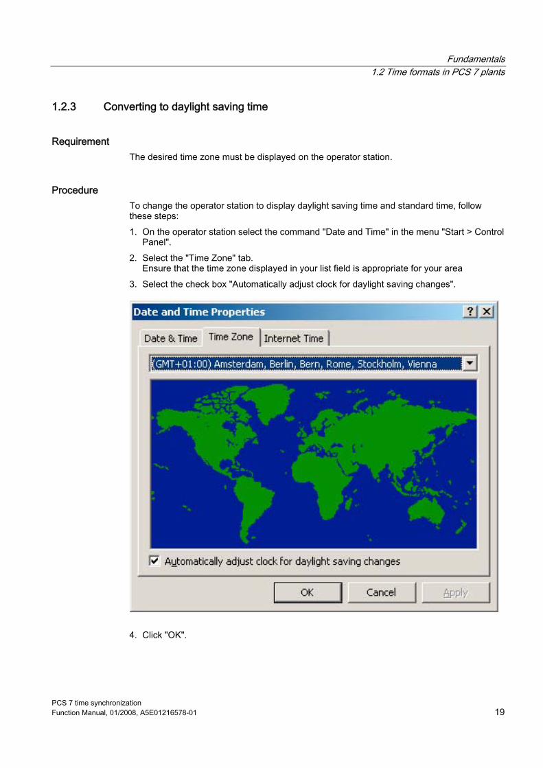
Procedure To change the operator station to display daylight saving time and standard time, follow these steps: 1. On the operator station select the command "Date and Time" in the menu "Start > Control
Panel". 2. Select the "Time Zone" tab.
Ensure that the time zone displayed in your list field is appropriate for your area 3. Select the check box "Automatically adjust clock for daylight saving changes".
4. Click "OK".

Fundamentals 1.2 Time formats in PCS 7 plants
PCS 7 time synchronization 20 Function Manual, 01/2008, A5E01216578-01
All time information for the operator station will be output in the local time of the selected time zone, including daylight saving time changes, and it will be converted at the correct point in time.
Note If you operate a plant over multiple time zones that takes daylight saving time and standard time into account, use the uniform time UTC for display on the operator station as well. You therefore have a uniform basis for process analysis at all plant units.
Note
You can configure the switch to daylight saving time or point in time for the switch for each specific country. Since PCS 7 always works with UTC internally, these changes do not influence the PCS 7 processes. If you have set the display of the operator station to the local time of these countries, and have set automatic conversion of daylight saving time to standard time, then the time conversion will also take place automatically in this case as well.

Fundamentals 1.2 Time formats in PCS 7 plants
PCS 7 time synchronization Function Manual, 01/2008, A5E01216578-01 21
1.2.4 Checking the time
Methods for checking the time The following possibilities are available for checking the time in the plant: 1. Use the "w32tm" operating system function to set the time difference to an additional
computer. 2. In the Graphics Designer you can create a diagnostics screen where the different servers
are represented with their times. Configure a text field for the server name for each server. For each text field configure an I/O field; its value is supplied by the return value of the "GetTimeFromPC" script. This script is available in the appendix of this documentation.
Note You can find more information about the w32tm command by entering "w32TM/?" in the Windows Run dialog or under the following Internet address: http://go.microsoft.com/fwlink/?LinID=42984
Checking time synchronization with w32/tm When you enter the command "w32tm/stripchart/computer:<destination>[/period:<time>]dataonly][/samples:<number>]", you will see a diagram that displays the deviation (offset) of the computer currently in use to the specified computer.
Command switches Meaning computer:<destination> The computer used as the base for the deviation measurement. period:<time> Time in seconds between updates. The default value is 2 seconds. dataonly: Show only data and no graphics. samples:<number> Stops sampling after specified number of time samples. If this value
is not specified, time samples are sampled as long as the key combination "Ctrl-C" is pressed.

Fundamentals 1.2 Time formats in PCS 7 plants
PCS 7 time synchronization 22 Function Manual, 01/2008, A5E01216578-01
Example: Check time synchronization 1. Select the menu command "Start > Settings > Accessories > Command Prompt." 2. Enter "w32tm/stripchart/computer:<DC1>" in the dialog.
You will see a diagram showing the deviation of DC1 to the computer currently in use.
Note Note that restrictions can be configured on the operator stations. If you have configured the situation that no input prompts are possible in runtime, then the w32tm function cannot be executed. If you want to use this function you must first change the configuration of the runtime in this case.
Fundamentals 1.2 Time formats in PCS 7 plants
PCS 7 time synchronization Function Manual, 01/2008, A5E01216578-01 23
1.2.5 Time levels for a PCS 7 plant (stratum)
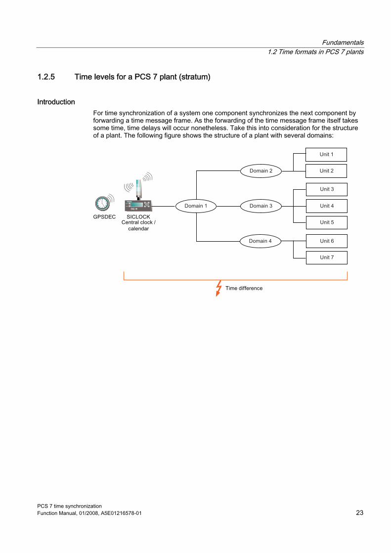
Introduction For time synchronization of a system one component synchronizes the next component by forwarding a time message frame. As the forwarding of the time message frame itself takes some time, time delays will occur nonetheless. Take this into consideration for the structure of a plant. The following figure shows the structure of a plant with several domains:

Fundamentals 1.2 Time formats in PCS 7 plants
PCS 7 time synchronization 24 Function Manual, 01/2008, A5E01216578-01
Definition stratum Within a PCS 7 system a component, e.g. the OS server, gets the determining time from an external clock and forwards this time to other components that will be synchronized. Each computer that receives the time and/or forwards the time is designated as time server. All time servers form a hierarchy with higher-level and lower-level time servers. Relative position within this hierarchy is designated with a number; the "stratum". Multiple time servers can be located within one stratum. In this case they receive the time message frame at the same time. Thus the stratum indicates the following: ● How far away the respective time server is from the time source ● Which time servers are located on the same time level The following figure shows time synchronization through four strata:
The above example shows time synchronization with the following structure: ● The actual time source is an atomic clock, e.g. the atomic clock of the German Federal
Physical Technical Institute (Physicalisch-Technichen Bundesanstalt (PTB)) in Braunschweig.
● The central SICLOCK plant clock receives the precise time from this atomic clock via the DSF 77 reception service. Thus SICLOCK is located in stratum 1. SICLOCK forwards the time to the domain controller 1 in stratum 2. This time server connected to the time source is also referred to as a primary server.
● The primary server forwards the time to multiple domain controllers in stratum 3. ● The domain controllers synchronize the time of their own process units in stratum 4.

Fundamentals 1.2 Time formats in PCS 7 plants
PCS 7 time synchronization Function Manual, 01/2008, A5E01216578-01 25
Meaning of the strata for a PCS 7 plant The higher the stratum, the greater the distance between the time servers in this stratum and the original time source. Because forwarding the received time in the network also takes time, the time of lower strata time servers is more precise than is the time of higher strata time servers. Consequently when planning a plant that will be synchronized, precisely consider which hierarchy is practical for reception and forwarding of time.
Rules for planning a PCS 7 plant taking strata into account Comply with the following rules when planning time synchronization to ensure that the time deviation of the time master is not too high relative to the components in the lowest stratum: ● Use as few strata as possible. ● In most cases using a maximum of four strata is recommended. ● Use the same strata for the same structure elements.

Fundamentals 1.3 Time synchronization in PCS 7 - mode of operation
PCS 7 time synchronization 26 Function Manual, 01/2008, A5E01216578-01
1.3 Time synchronization in PCS 7 - mode of operation
1.3.1 Master/slave principle for time synchronization
Introduction One system component must be the clock for all other components so that all process control system components work with an identical time. The PCS 7 component that functions as clock is referred to as the time master. Components that receive the time are referred to as time slaves.
Time master The time master is responsible for distributing the time signal to the PCS 7 components (the time slaves) that will be synchronized. The time master gets its time via one of the following clocks: ● DCF 77 reception service ● GPS reception service ● SICLOCK TS/TM ● Domain controller Usually you configure one of the following PCS 7 components as time master: ● OS server ● Central plant clock SICLOCK TM
SICLOCK TM is synchronized via a time signal, e.g. a SICLOCK GPS decoder or a SICLOCK DCFRS receiver. SICLOCK TM synchronizes the stations via Industrial Ethernet.
● Central plant clock SICLOCK TS An OS server can be time master in two ways: ● Active time master
The active time master outputs the time message frames to the time slaves and to the passive time masters.
● Passive time master A passive time master takes over the function of the active time master if the active time master should fail.

Fundamentals 1.3 Time synchronization in PCS 7 - mode of operation
PCS 7 time synchronization Function Manual, 01/2008, A5E01216578-01 27
Time slave Time slaves are PCS 7 components that receive the time message frame from a time master to set their internal clock. Usually you define the following PCS 7 components as time slave: ● OS clients ● Automation systems
Internal clocks as sources for the time maser Use an internal clock as time source to ensure uniform time system wide. This time does not have to agree with real UTC or with real local time. The table below shows which internal clocks are possible as a source for the active time master:
Internal clocks Requirement Active time master OS The real time is not important for the project. Operator station Domain controller The computer to be synchronized belongs to a
Windows 2000/2003 domain Domain controller
External clocks as sources for the time master Use an external clock as time source to ensure uniform system-wide time that agrees with UTC or with local time. The table below shows which external clocks are possible as source for the time master:
External clocks Requirement Active time master DCF77RS COM interface OS server with SICLOCK TM/TS GPSDEC COM interface OS server with SICLOCK TM/TS SICLOCK TS/TM with DCF 77 or GPS
OS server Domain controller
NTP server Internet connection Domain controller

Fundamentals 1.3 Time synchronization in PCS 7 - mode of operation
PCS 7 time synchronization 28 Function Manual, 01/2008, A5E01216578-01
Time master and time slave interaction Time synchronization is a WinCC application that is operated as a master slave system. Each operator station can be configured as time master with or without radio-controlled time reception service. For acceptance of time from an external time source the time master is synchronized with this time source in regular time intervals. The reference time for the connected and appropriately configured components is then supplied by the synchronized RTC (Real Time Clock). In the following figure the OS server is time master for the plant. It obtains the precise time via SICLOCK. The OS server synchronizes all time slaves with this time. OS clients and automation systems are configured as time slaves.
Time master and time slave interaction for redundancy In a redundant system multiple OS time masters can be present. In the figure below two OS servers are configured as time masters with connection to the central plant clock SICLOCK. OS clients and automation systems are time slaves and receive the time from the respective current time master.

Fundamentals 1.3 Time synchronization in PCS 7 - mode of operation
PCS 7 time synchronization Function Manual, 01/2008, A5E01216578-01 29
When booting all time masters first check whether a time master is already active and sending time message frames on the bus. The wait time until a time message frame must arrive after booting is 4x the set synchronization interval. If a time master receives a time message frame from a different time master then it becomes a time slave. If after the wait time elapses a time message frame has not been received, then the time slave sends a time message frame itself as time master. Redundant time masters detect their function as time slave through the receipt of the time message frame and then synchronize their clock to the received time. They then check the cyclic receipt of time message frames from the active master with their clock in accordance with the synchronization interval received in the time message frame. If three successive time message frames fail, the first redundant master that notices the failure will start sending the time message frames. This mechanism ensures that only one master sends time message frames at any time. All time slaves and redundant masters on the plant bus synchronize their internal clock with the received time message frames. The time is changed in the synchronization process, as follows: ● Deviation ± 5 s: Delay/accelerate the time ● Deviation > 5s: Immediate change (error: Data packets sent off prior to the change will
have more recent time stamps than those sent off later)
Note Only OS servers that are connected on the plant bus can be redundant time masters.
Two communications processors, e.g. CP 443-1, are necessary for time synchronization of redundant automation systems on the rack. You will find more information in the following manuals: ● Process Control System PCS 7 V 7.0, High-availability process control systems ● Process Control System PCS 7 V7.0; Operator Station

Fundamentals 1.3 Time synchronization in PCS 7 - mode of operation
PCS 7 time synchronization 30 Function Manual, 01/2008, A5E01216578-01
1.3.2 Network environment of a PCS 7 plant
Time synchronization in a domain In a Windows domain the domain controller (DC) is the time master. The domain controller receives the time via a SICLOCK connected to the COM interface, with connection to GPSDEC or DCFRS.
Synchronization in a domain is executed as follows: ● Time synchronization via terminal bus
The domain controller (DC) receives the time from the central SICLOCK plant clock and synchronizes the terminal bus. The OS servers receive the time via the terminal bus from the domain controller. The OS clients receive their time from one of the connected OS servers.
● Time synchronization via plant bus The plant bus and thus the connected automation systems are synchronized by the OS server that first starts up in process mode. Thus it becomes the active time master.
Note For highly precise synchronization of the plant bus you can connect a SICLOCK TM with GPSDEC as time master on the plant bus. In this case all automation devices will be synchronized by the SICLOCK TM.
Note When the OS clients are to be located in the same stratum as the OS server, you can also receive the time directly from the domain controller and be synchronized by it.
Fundamentals 1.3 Time synchronization in PCS 7 - mode of operation
PCS 7 time synchronization Function Manual, 01/2008, A5E01216578-01 31
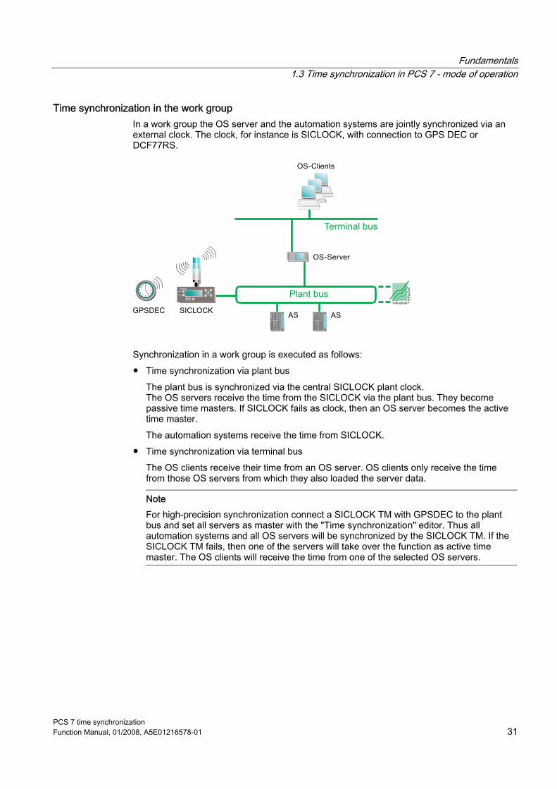
Time synchronization in the work group In a work group the OS server and the automation systems are jointly synchronized via an external clock. The clock, for instance is SICLOCK, with connection to GPS DEC or DCF77RS.
Synchronization in a work group is executed as follows: ● Time synchronization via plant bus
The plant bus is synchronized via the central SICLOCK plant clock. The OS servers receive the time from the SICLOCK via the plant bus. They become passive time masters. If SICLOCK fails as clock, then an OS server becomes the active time master. The automation systems receive the time from SICLOCK.
● Time synchronization via terminal bus The OS clients receive their time from an OS server. OS clients only receive the time from those OS servers from which they also loaded the server data.
Note For high-precision synchronization connect a SICLOCK TM with GPSDEC to the plant bus and set all servers as master with the "Time synchronization" editor. Thus all automation systems and all OS servers will be synchronized by the SICLOCK TM. If the SICLOCK TM fails, then one of the servers will take over the function as active time master. The OS clients will receive the time from one of the selected OS servers.

Fundamentals 1.3 Time synchronization in PCS 7 - mode of operation
PCS 7 time synchronization 32 Function Manual, 01/2008, A5E01216578-01
Time synchronization on redundant (fault tolerant) busses To prevent production standstill if the bus system fails, install the busses of a PCS 7 plant redundantly. If one terminal bus fails communication via the redundant bus will remain intact. Time synchronization is taken over by the domain controller. If the first domain controller (PDC emulator) for time synchronization fails, then a different domain controller will automatically take over time synchronization. In the failure period time synchronization is based on Windows mechanisms. Monitor the binary output of the SICLOCK TM so that failure of the SICLOCK TM is reported. Additional information on assigning parameters of the binary output are provided in the SICLOCK TM documentation. Configure a message with priority "16" in the CFC for this binary output. More detailed information on configuring the message is available in the documentation Process Control System PCS 7, Operator Station. The following figure shows the configuration with a redundant terminal bus:
The synchronization is executed as follows: ● SICLOCK supplies the exact time. ● The domain controller distributes the received time to the terminal bus. ● Time master is the operator station. ● WinCC actively obtains the time from the terminal bus. ● If SICLOCK fails, the time is taken over from the domain controller and distributed on the
terminal bus and plant bus. ● If the COM interface (and thus the connection from SICLOCK to the domain controller)
fails, then the terminal bus will receive the time from the domain controller. The plant bus will continue to get the time from SICLOCK. Caution: The time of the terminal bus may deviate from that of the plant bus in this case!

Fundamentals 1.3 Time synchronization in PCS 7 - mode of operation
PCS 7 time synchronization Function Manual, 01/2008, A5E01216578-01 33
Time synchronization on separate plant busses with one SICLOCK If you synchronize two or more independent plant busses with one SICLOCK as time source, then you must ensure that no other communication between the busses takes place in addition to the handover of time signals. For this purpose use a switch with port lock function, e.g. the SCALANCE X414-3E. If port lock is selected, bidirectional communication is not possible. In this manner only the SIMATIC time message frame is transmitted on the plant bus; no other data is transmitted on the plant bus.

Fundamentals 1.3 Time synchronization in PCS 7 - mode of operation
PCS 7 time synchronization 34 Function Manual, 01/2008, A5E01216578-01

PCS 7 time synchronization Function Manual, 01/2008, A5E01216578-01 35
Configurations for time synchronization of a PCS 7 plant 22.1 Overview of recommended configurations
Introduction Various techniques are possible for time synchronization. To avoid undesired results, the structure of a plant with time synchronization requires careful planning. To facilitate the planning of your plant use one of the following configurations. The following table shows the four recommended configurations:
Plant type Recommend
ation Configuration
Time synchronization in a work group
1 2
Time synchronization with central time master Time synchronization without central time master
Time synchronization in a Windows domain
3 4
Time synchronization with central time master Time synchronization without central time master
Configuration of a PCS 7 plant in a work group The following figure schematically shows a PCS 7 plant that is structured as work group:

Configurations for time synchronization of a PCS 7 plant 2.1 Overview of recommended configurations
PCS 7 time synchronization 36 Function Manual, 01/2008, A5E01216578-01
Configuration of a PCS 7 plant in a domain In a Windows domain the members of the domain are grouped together. The domain controller manages the user rights of the domain members, among other things. The following figure schematically shows a PCS 7 domain with two domain controllers (DC1 and DC2):
Note In Windows domains the configurations for time synchronization vary depending on the hierarchy depth of the domain structure. Consequently recommendations 3 and 4 are again differentiated according to different hierarchy depth. Configuration of time synchronization is shown in the following sections: - "Configuration of time synchronization with central time master in a Windows domain with a hierarchy" - "Configuration of time synchronization without central time master in a Windows domain with multiple hierarchies"
Note
For high-precision time stamping we recommend using SICLOCK TM with DCF 77 or GPS for the plant bus and the domain controller. If the SICLOCK TM fails, a uniform time is ensured. The precision in this case no longer satisfies the requirements for high-precision time stamping; the consistency of the time information however remains intact.
See also Configuration of time synchronization with central time master in a Windows domain with a hierarchy (Page 44) Configuration of the time synchronization in a Windows domain with multiple hierarchies (Page 46)

Configurations for time synchronization of a PCS 7 plant 2.2 Configurations for time synchronization in a work group
PCS 7 time synchronization Function Manual, 01/2008, A5E01216578-01 37
2.2 Configurations for time synchronization in a work group
2.2.1 Configuration of time synchronization with central time master in a work group
Configuration The following figure schematically shows the recommended configuration of time synchronization of a work group with central time master:
Time master: Central plant clock SICLOCK TM/TS on the plant bus ● Time synchronization on the plant bus
– Time master Time master is the SICLOCK TM/TS connected to the plant bus as central plant clock. It sends a high-precision broadcast time signal on the plant bus.
– Time source SICLOCK TM/TS synchronizes itself via an external clock, e,g, DFC 77 radio receiver or a GPS receiver module.
– All AS's are configured as time slaves. – The OS servers are configured as so-called cooperative masters. If the SICLOCK no
longer sends a time signal, then an OS server becomes active time master and then sends time signals itself on the plant bus, as a replacement.
● Time synchronization on the terminal bus – The time signal received from the plant bus takes over WinCC time synchronization at
runtime of a PCS 7 project and sets the system time of the other OS servers. – The OS clients are likewise configured as time slaves and receive their time signal
from the OS server.

Configurations for time synchronization of a PCS 7 plant 2.2 Configurations for time synchronization in a work group
PCS 7 time synchronization 38 Function Manual, 01/2008, A5E01216578-01
Configuration steps The following table shows the configuration steps that are necessary for the configuration described above, and the chapters of this documentation where the steps are described:
Step Time
synchronization components
Configuration steps Configuration instructions in chapter
1
SICLOCK with GPS or DCF77
Clocks - connection, installation, and parameter assignment
"Configuring SICLOCK" "Configuring DCF 77 reception service" "Configuring GPS"
2 AS
Assigning parameters for AS as time slaves
"How to set time synchronization on the AS".
3 CP Assigning parameters for CP for the plant bus
"How to set time synchronization on an AS".
4 OS server
Parameter assignment for an OS server as cooperative master
"How to set time synchronization on an OS in a work group with central time master."
5 OS server
Parameter assignment for redundant OS servers
"How to set time synchronization on an OS in a work group with central time master."
6
OS clients
Parameter assignment for OS clients
"How to set time synchronization on an OS in a work group with central time master."

Configurations for time synchronization of a PCS 7 plant 2.2 Configurations for time synchronization in a work group
PCS 7 time synchronization Function Manual, 01/2008, A5E01216578-01 39
2.2.2 Configuration of time synchronization without central time master in a work group
Configuration The following figure schematically shows the recommended configuration of a PCS 7 plant with time synchronization in a work group without central time master:
● Time master: OS server ● Time synchronization on the terminal bus
– The OS server transmits the time message frame to the plant bus. The OS server is configured as time master on these busses. Configure the OS clients as time slaves. In this case they get their time signal from the OS server.
● Time synchronization on the plant bus – All AS are configured as time slaves.

Configurations for time synchronization of a PCS 7 plant 2.2 Configurations for time synchronization in a work group
PCS 7 time synchronization 40 Function Manual, 01/2008, A5E01216578-01
Configuration steps The following table shows the configuration steps that are necessary for the configuration described above, and the chapters of this documentation where the steps are described:
Step Time
synchronization components
Configuration steps Configuration instructions in chapter
1 AS
Assigning parameters for all AS's as time slaves
"How to set time synchronization on an AS".
2 OS server
Parameter assignment for OS servers as time master
"How to set time synchronization on an OS in a work group without central time master."
3
OS clients
Parameter assignment for OS clients
"How to set time synchronization on an OS in a work group without central time master."
Note This manual describes only time synchronization with PCS 7 V7.0 SP1. Contact Customer Support if you wish to use V5-compatible mode.

Configurations for time synchronization of a PCS 7 plant 2.3 Configuration for time synchronization in a Windows domain
PCS 7 time synchronization Function Manual, 01/2008, A5E01216578-01 41
2.3 Configuration for time synchronization in a Windows domain
2.3.1 Configuration of time synchronization with central time master in a Windows domain with a hierarchy
Configuration The following figure schematically shows the recommended configuration of a PCS 7 plant in a Windows domain with central time master:
Time master: Plant central clock SICLOCK TM/TS on the plant bus and on the domain controller ● Time synchronization on the terminal bus
– Active time master: The time master is the domain controller (DC), which is configured as the master of the overall structure and/or the PDC emulator (usually the first installed domain controller).
– Time source The domain controller receives the time via a serial cable from the central plant clock SICLOCK TM/TS. The DCF 77 reception service that will be installed synchronizes this domain controller with the central plant clock.
– All additional plant PCs automatically become time slaves of the domain controller due to their membership in the domain (PDC emulator).

Configurations for time synchronization of a PCS 7 plant 2.3 Configuration for time synchronization in a Windows domain
PCS 7 time synchronization 42 Function Manual, 01/2008, A5E01216578-01
– The Windows time service, also known as W32Time, synchronizes the date and time of all computers in a Windows domain. Since Windows internal time synchronization is only synchronized every eight hours, the OS servers are additionally configured as time slaves of the domain controller (PDC emulator) via the WinCC time synchronization. PDC emulator is an operation master role of a PC. The PC with this role synchronizes the members of the domain every 8 hours.
Note You can find additional information about the Windows time service (W32Tm) at the following addresses: http://www.microsoft.com/germany/technet/prodtechnol/windowsserver/technologies/featured/ad/active-directory-betriebshandbuch-02.mspx http://technet2.microsoft.com/windowsserver/en/library/a0fcd250-e5f7-41b3-b0e8-240f8236e2101033.mspx
– Passive time master If the authenticated domain controller (PDC operation master) fails, another domain controller automatically takes over the time synchronization of the network.
– The OS clients are configured as time slaves of the connected OS servers and receive their time signal via the terminal bus.
– PCS 7 PCs that do not have WinCC time synchronization, for example BATCH PC or engineering station, are synchronized via an additionally installed DCF 77 reception service. As time master one of the domain controllers or an OS server is possible here.
● Time synchronization on the plant bus – Time master for the plant bus is the SICLOCK TM/TS connected to the plant bus as
central plant clock. It sends a high-precision broadcast time signal on the plant bus. SICLOCK synchronizes itself via an external clock, e.g. DCF 77 receiver or a GPS receiver module.
– The OS servers are configured as so-called cooperative masters. If the AS no longer sends a time signal then an OS server becomes time master and then sends time signals itself on the plant bus, as a replacement.
– All AS's are configured as time slaves.
Note You can learn about the procedure for configuring an authorized time server in Windows Server 2003 in the corresponding Microsoft literature at the following addresses: German: http://support.microsoft.com/kb/816042/de English: http://support.microsoft.com/kb/816042/EN-US

Configurations for time synchronization of a PCS 7 plant 2.3 Configuration for time synchronization in a Windows domain
PCS 7 time synchronization Function Manual, 01/2008, A5E01216578-01 43
Configuration steps The following table shows the configuration steps that are necessary for the configuration described above, and the chapters of this documentation where the steps are described:
Step Time
synchronization components
Configuration steps Configuration instructions in chapter
1
SICLOCK with GPS or DCF77
Clock - connection, installation, and parameter assignment
• "Configuring SICLOCK" • "Configuring DCF 77 reception
service" • "Configuring GPS"
2
DC
Parameter assignment for domain controller as time master
See Microsoft literature
3
OS clients
Parameter assignment for OS clients
• "How to set time synchronization on an OS in a domain with central time master."
4
PC e.g. BATCH
Parameter assignment for PCs without WinCC time synchronization via DCF 77
• "How to set time synchronization on a BATCH station."
• "How to set time synchronization on a Route Control station."
• "How to set time synchronization on the engineering station."
5
OS server
Parameter assignment for OS servers as cooperative time masters
• "How to set time synchronization on an OS in a domain with central time master."
6
AS
Assigning parameters for AS as time slaves
• "How to set time synchronization on the AS".

Configurations for time synchronization of a PCS 7 plant 2.3 Configuration for time synchronization in a Windows domain
PCS 7 time synchronization 44 Function Manual, 01/2008, A5E01216578-01
2.3.2 Configuration of time synchronization with central time master in a Windows domain with a hierarchy
Configuration The following figure schematically shows the recommended configuration of a PCS 7 plant with time synchronization without central time master in a domain.
● Time master: Domain controller (DC) with PDC emulator operation master role ● Time synchronization on the terminal bus
– Time master Time master is the domain controller with PDC emulator operation master role.
– Time source The domain controller receives the time via the NTP time server, which in turn receives the precise time via an DCF 77 receiver or GPS module.
– Passive time master If the authenticating domain controller (PDC operation master) fails, another domain controller automatically takes over the time synchronization within the network.
– Time slaves All additional plant PCs are time slaves of the domain controller due to their membership in the domain.
– PCS 7 PCs that do not have WinCC time synchronization, for example BATCH PC or engineering station, are synchronized via an additionally installed DCF 77 reception service. As time master one of the domain controllers or an OS server is possible here.

Configurations for time synchronization of a PCS 7 plant 2.3 Configuration for time synchronization in a Windows domain
PCS 7 time synchronization Function Manual, 01/2008, A5E01216578-01 45
● Time synchronization on the plant bus – All AS's on the plant bus are configured as time slaves. – The OS servers receive the time signal via the terminal bus from the authorized
domain controller (PDC operation master). The OS servers on the plant bus are configured as cooperative masters. They switch to "time master" mode when they no longer receive a time signal. All other OS servers are time slaves.
Note The procedure for configuring the domain controllers as time masters is described in the appropriate Microsoft literature at the addresses: German: http://support.microsoft.com/kb/816042/de English: http://support.microsoft.com/kb/816042/EN-US
Configuration steps The following table shows the configuration steps that are necessary for the configuration described above, and the chapters of this documentation where the steps are described:
Step Time synchronization
components Configuration steps Configuration instructions in
chapter 1
DC
Parameter assignment for domain controller as time master
See Microsoft literature
2
PC
Parameter assignment for PCs without WinCC time synchronization via DCF 77
• "How to set time synchronization on a BATCH station."
• "How to set time synchronization on a Route Control station."
• "How to set time synchronization on the engineering station."
3
OS server
Parameter assignment for OS servers as cooperative time masters
• "How to set time synchronization on an OS in a work group with central time master."
4
AS
Assigning parameters for AS as time slaves
• "How to set time synchronization on the AS".

Configurations for time synchronization of a PCS 7 plant 2.3 Configuration for time synchronization in a Windows domain
PCS 7 time synchronization 46 Function Manual, 01/2008, A5E01216578-01
2.3.3 Configuration of the time synchronization in a Windows domain with multiple hierarchies
Sample configuration The following figure shows a sample configuration for time synchronization in a Windows domain with multiple hierarchies:
Rules To avoid time jumps in a Windows domain with multiple hierarchies, comply with the following rules when structuring the hierarchies: 1. In a domain with multiple hierarchies ensure that the same structures are found on the
same levels. Thus you will avoid undesired time differences. Additional information is available in the sections "Time levels of a PCS 7 system" and "PCS 7 plant taking strata into account".
2. Only form one hierarchy level under the root domain. If additional domains are necessary, then arrange these domains on the same hierarchy level as the existing sub-domains.

PCS 7 time synchronization Function Manual, 01/2008, A5E01216578-01 47
Planning time synchronization 33.1 Selecting the time master
Plant structure with different time masters For a time synchronous plant you need a time master to which the additional plant components are synchronized. The following table shows which components serve as time master:
Time master Possible time
sources Bus Time master
forwards the time to... Forwards the time to ...
Conditions
Terminal bus OS clients - OS server
- RTC - GPS - DCF 77
Plant bus CP of the OS servers that are active time masters
AS slaves -
Terminal bus Domain controller Terminal bus with OS clients
- SICLOCK TM / TS
- GPS - DCF 77
Plant bus OS server AS slaves
- -
OS clients - Plant bus AS
Domain controller
- GPS - DCF 77 - NTP server
Terminal bus OS server
SICLOCK TM AS
PC
- PC time - GPS - DCF 77 - NTP
Parameter assignment as as time master

Planning time synchronization 3.2 Time synchronization for existing plants
PCS 7 time synchronization 48 Function Manual, 01/2008, A5E01216578-01
3.2 Time synchronization for existing plants
Criteria for time synchronization for existing plants Compare the configuration of your existing plant with the configurations presented in this documentation and configure the time synchronization according to the available configuration.

PCS 7 time synchronization Function Manual, 01/2008, A5E01216578-01 49
Configuring time synchronization 44.1 Introduction
Components To synchronize the time of your plant it is necessary to configure all nodes for the time synchronization To do this configure the following components depending on configuration: ● Time receivers
You configure the external time receiver when you no longer synchronize the time with an internal timer.
● Operator station Configure the OS server(s) and the OS clients.
● Coupling modules Configure the CPs for time synchronization.
● Automation system You configure the CPU and the CPs CPs 443-1, 443-5 Extended of the AS
● Additional plant components The following components should be included in the time synchronization as needed: – SIMATIC BATCH – SIMATIC Route Control – SIMATIC BOX – SIMATIC IT – Engineering station

Configuring time synchronization 4.2 Configuring the time receiver
PCS 7 time synchronization 50 Function Manual, 01/2008, A5E01216578-01
4.2 Configuring the time receiver
4.2.1 Configuring SICLOCK TM
Introduction The central plant clock is the core piece for time synchronization of plants. It manages the time centrally for the entire plant and synchronizes all other plant components via their interfaces. The following table shows which central plant clocks are offered by the SICLOCK system:
Central plant clock
Ethernet Inputs Outputs GPS radio clock
DCF 77 radio clock
SICLOCK TM RJ45 or ITP 2 x digital 8 x digital GPSDEC GPS1000
DCFRS Industry version
SICLOCK TS RJ45 or ITP 1 x IRIG A+B 1 x digital
1 x IRIG A+B 3 x digital
GPS1000 DCFRS Industry version
The following figure shows a SICLOCK TM:
Set the parameters as described in the SICLOCK documentation so that the SICLOCK correctly synchronizes the time of your plant.

Configuring time synchronization 4.2 Configuring the time receiver
PCS 7 time synchronization Function Manual, 01/2008, A5E01216578-01 51
Configuration steps The following table shows the configuration steps that are necessary to use the SICLOCK for time synchronization of a PCS 7 plant:
Step Configuration steps 1 Wire GPS decoder with SICLOCK 2 Assign parameters to the GPS decoder 3 Assign parameters for the SICLOCK 4 Connect the SICLOCK to the PCS 7 plant 5 Configure the components depending on plant configuration and network topology
components
Configuration setting for a PCS 7 plant The following is an example of the settings for a PCS 7 plant, whose AS is synchronized using the SIMATIC mode.
Procedure for SIMATIC mode Follow these steps to configure SICLOCK TM as clock for time synchronization of this plant: 1. Call the parameters of the SICLOCK TM. 2. Set the parameter 338/6A Ethernet to "On" 3. Select an unassigned IP address on your plant bus and configure the SICLOCK TM for it
at the 343/6A parameter.

Configuring time synchronization 4.2 Configuring the time receiver
PCS 7 time synchronization 52 Function Manual, 01/2008, A5E01216578-01
Procedure for NTP mode The NTP mode is exclusively used by CPU 416-3 PN/DP (6ES7416-3ER05-0AB0) and CPU 414-3 PN/DP (6ES7414-3EM05-0AB0). Use the SIMATIC mode for all other CPUs. Follow these steps to configure SICLOCK TM as clock for the time synchronization of this plant: 1. Call the parameters of the SICLOCK TM. 2. Set the parameter 338/6A Ethernet to "On" 3. Select an unassigned IP address on your plant bus and configure the SICLOCK TM for it
at the 343/6A parameter. 4. For the 550/6F "SNTP-Server" parameter enter "any/unicast". 5. Set the synchronization type to "Master" in HW Config in the SIMATIC Manager, and set
a time interval of 10 seconds.
Note The parameters of the SICLOCK TM are pre-set as standard as described above. If the parameters have not been changed then the settings described above are not necessary. In this case check whether the parameter settings are correct. Please note the following: • The complete configuration settings of the SICLOCK TM are provided in the
documentation of the SICLOCK TM. • If you want to use a different central plant clock, set the parameters of this clock
according to the settings for the SICLOCK TM. • The SICLOCK TM supports a maximum of 50 NTP requests per second.
Note To activate the NTP server on SICLOCK TM/TS assign parameters for SICLOCK TM/TS in addition to the normal network operation as follows: 1. In the parameter 343/6A "IP Source Addr." in the menu 6A assign the device an IP
address. 2. Set the parameters 344/6A "Subnet mask" and possibly 345/6A "Default gateway" in
the menu 6A in accordance with the IP network. 3. In the menu 6F set the parameter 550/6F "SNTP Server" = "any/unicast".
Note A change of the parameters in the network menu 6A ...6F is only possible if network operation of the device is temporarily switched off. First set the parameter 338/6A "Ethernet" = off. After you have set the parameters, switch network operation on again (parameter 338/6A "Ethernet" = on or synchronized).
Configuring time synchronization 4.2 Configuring the time receiver
PCS 7 time synchronization Function Manual, 01/2008, A5E01216578-01 53
4.2.2 Configuring DCF 77 reception service for Windows
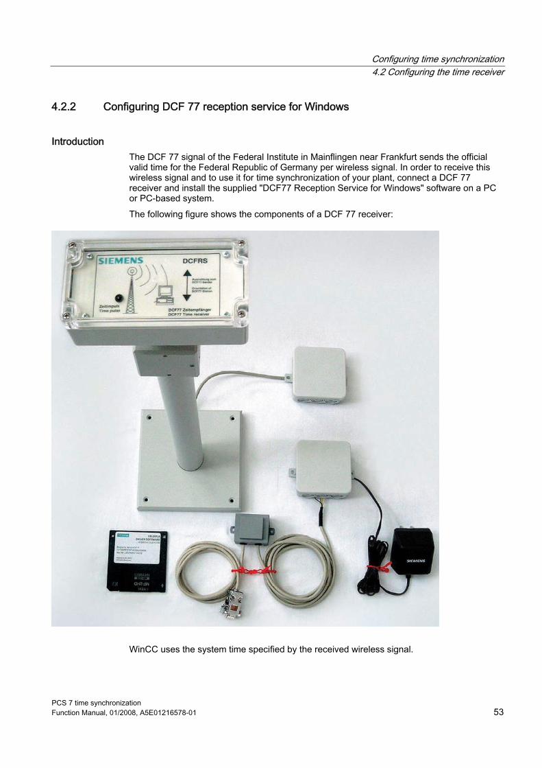
Introduction The DCF 77 signal of the Federal Institute in Mainflingen near Frankfurt sends the official valid time for the Federal Republic of Germany per wireless signal. In order to receive this wireless signal and to use it for time synchronization of your plant, connect a DCF 77 receiver and install the supplied "DCF77 Reception Service for Windows" software on a PC or PC-based system. The following figure shows the components of a DCF 77 receiver:
WinCC uses the system time specified by the received wireless signal.

Configuring time synchronization 4.2 Configuring the time receiver
PCS 7 time synchronization 54 Function Manual, 01/2008, A5E01216578-01
Configuration steps The following table shows the steps that are necessary for configuring the DCF 77 radio clock.
Step Configuration steps 1 Install the driver software for the DCF 77 radio clock 2 Activate the reception service 3 Connect the receiver cable 4 Align the antenna 5 Set initial commissioning 6 Set after initial commissioning
Structure of the SICLOCK DCF 77 radio clock The SICLOCK DCF 77 wireless clock consists of the following components: ● An antenna head with or without antenna frame ● The supplied software for installation on the target system that will be synchronized The DCF 77 receiver is located in the antenna head, its demodulated DCF 77 signal is fed into the target system via industry standard RS232. The DCF 77 receiver is supplied with power via this interface. You do not need an additional power supply on the receiver.
Installing and activating DSF 77 receivers To install the software for the DCF 77 receiver, proceed as follows: 1. Switch the PC on. 2. Insert the diskette/CD with the driver software into the drive. 3. Start the SETUP.EXE file 4. Follow the installation instructions.
The DCF 77 receiver service is stored as an icon in the Control Panel. The DCF 77 reception service is started automatically when booting the system.
5. Activate the DCF 77 reception service in the Control Panel. 6. Connect the DCF 77 receiver cable to the selected COM port.

Configuring time synchronization 4.2 Configuring the time receiver
PCS 7 time synchronization Function Manual, 01/2008, A5E01216578-01 55
Align the antenna To optimally align the receiver, proceed as follows: 1. Configure the receiver so that the control LED flashes every second. 2. Check that the receiver is on the side of the building facing Frankfurt.
Note If you do not get clear reception then note the following rules: • Maintain as great a distance as possible between the receiver and PC, monitors, laser
printers, motors, motorized drives, or similar sources of interference. • Keep the receiver away from metal surfaces and steel-reinforced concrete.
Note Additional instructions for connection and optimal alignment of the receiver are provided in the operating instructions supplied with the DCF 77 receiver.
Set DCF 77 reception service for commissioning To commission the DCF 77 reception service, proceed as follows: 1. In the menu "Start > Settings > Control Panel" select the command "DCF-77".

Configuring time synchronization 4.2 Configuring the time receiver
PCS 7 time synchronization 56 Function Manual, 01/2008, A5E01216578-01
2. Enter the COM interface on which the external DFC 77 receiver is connected. Default: COM2
3. Set the signal form prescribed by the card manufacturer. Example: DCF77 demodulated
4. Select the following check boxes in the "Event Protocol" area: – Time comparisons – Each valid time message frame – Changes in signal quality
Set DCF 77 reception service after commissioning To set the DCF 77 reception service after commissioning, proceed as follows: 1. In the menu "Start > Settings > Control Panel" select the command "DCF-77". 2. Deselect the check boxes "Time comparisons" and "Each valid time message frame" in
the "Event Protocol" area:

Configuring time synchronization 4.2 Configuring the time receiver
PCS 7 time synchronization Function Manual, 01/2008, A5E01216578-01 57
4.2.3 Configuring GPS
Introduction The DFC 77 radio clock signal is limited to a range of 800 km from Frankfurt am Main. In regions where the DCF 77 radio signal is not received, use of a GPS receiver is recommended. The GPS receiver determines the UTC via the satellite-based GPS system (Global Positioning system). Due to the country-specific installation of Windows on the OS the sent UTC is converted to the time valid in the respective country. For reception of the precise time reception of the signal from one of the 24 satellites suffices. With the GPS module the global use of SIMATIC PCS 7 is also possible with inter-plant time synchronization. The following figure shows the GPS receiver using GPSDEC or synchronizing the central plant clock, SICLOCK TM.

Configuring time synchronization 4.2 Configuring the time receiver
PCS 7 time synchronization 58 Function Manual, 01/2008, A5E01216578-01
Wiring The following figure shows how the GPS decoder is connected to the SICLOCK TM:
Configuration steps The GPS satellite receiver is delivered with the "DCF77 reception service" software. The following table shows the steps that are necessary for configuring the GPS.
Step Configuration steps 1 Configuring DCF 77 reception service for Windows (see section "Configuring DCF 77
reception service for Windows") 2 Install the GPS driver software 3 Activate DCF 77 reception service 4 Plug in the receiver cable 5 Align receiver
Installing and activating GPS receivers To receive the system time with radio precision from the GPS satellites, proceed as follows: 1. Switch the PC on. 2. Place the supplied driver diskette in the diskette drive. 3. Activate the DCF 77 reception service in the Control Panel. 4. Connect the GPS receiver cable to the SICLOCK TM (see "Wiring" about).

Configuring time synchronization 4.2 Configuring the time receiver
PCS 7 time synchronization Function Manual, 01/2008, A5E01216578-01 59
Align the GPS antenna To optimally align the GPS receiver, proceed as follows: 1. Install the GPS antenna. 2. Align the antenna vertically to the sky.
With other angles the synchronization can fail temporarily because a satellite is not in the reception window.
Note Do not mount the antenna at locations that are in danger of lightning strike. If not otherwise possible attach the antenna to the interior of high windows.
See also Configuring DCF 77 reception service for Windows (Page 53)

Configuring time synchronization 4.3 Configuring the time synchronization with multiple buses/networks
PCS 7 time synchronization 60 Function Manual, 01/2008, A5E01216578-01
4.3 Configuring the time synchronization with multiple buses/networks
4.3.1 Configuring time synchronization for separate plant buses with a single SICLOCK TM/TS
Introduction To ensure time synchronization also for separate plant networks, only the time message frame of the SICLOCK TM/TS is forwarded on to the different plant busses. For this purpose use a switch with port lock function, e.g. the SCALANCE X414-3E. The port lock function suppresses the bidirectional communication between separate plant busses.
To configure time synchronization for separate plant busses, proceed as follows: 1. Connect to a switch with port lock function 2. Assign parameters for the SICLOCK
Step sequence of the configuration: Connect SICLOCK TM/TS to a switch with port lock function 1. Assign separate ports to the plant busses in the switch configuration. 2. Select "enable lock" for the ports. 3. Assign a MAC address to the SICLOCK TM/TS. 4. Connect the SICLOCK TM/TS to the switch. 5. Assign parameters for the synchronization message frame of the SICLOCK TM/TS. 6. Check to ensure that only the SICLOCK TM/TS is shown in the forwarding table. If
additional entries are present wait until the ageing time of 40 seconds elapses. After this period elapses the entries are deleted.
7. Connect the plant busses to the switch. 8. Check to ensure that only the SICLOCK TM/TS is shown in the forwarding table. If
addresses from the plant busses are displayed then correct the port configuration.

Configuring time synchronization 4.3 Configuring the time synchronization with multiple buses/networks
PCS 7 time synchronization Function Manual, 01/2008, A5E01216578-01 61
Assign parameters SICLOCK TM/TS in the SIMATIC mode To assign a synchronization message frame in the SIMATIC mode to SICLOCK TM/TS, configure the parameters as shown below:
Parameter Value 341/6A "Source addr. part 0" <MAC address> 342/6A "Source addr. part 1" <MAC address> 339/6A "LAN connection" 350/6B "Addr. 1 protocol" "Layer 2 - S5" 351/6B "Send addr. 1" "Each second" 353/6B "Addr. 1 dest. 0" "FFFFFF" 354/6B "Addr. 1 dest. 1" "FFFFFF" 338/6A "Ethernet" "On" or "synchronized"
4.3.2 Configuring for multiple plants with their own timer
Router To ensure time synchronization for multiple plants with autonomous timer as well, the time message frame should not be forwarded to other plants. For this block the port for the time message frame. Additional information on blocking ports is provided in the documentation for the router.
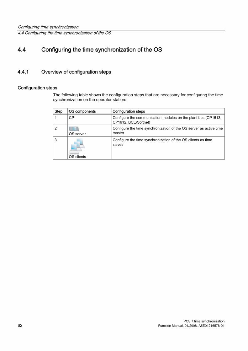
Configuring time synchronization 4.4 Configuring the time synchronization of the OS
PCS 7 time synchronization 62 Function Manual, 01/2008, A5E01216578-01
4.4 Configuring the time synchronization of the OS
4.4.1 Overview of configuration steps
Configuration steps The following table shows the configuration steps that are necessary for configuring the time synchronization on the operator station:
Step OS components Configuration steps 1 CP Configure the communication modules on the plant bus (CP1613,
CP1612, BCE/Softnet) 2
OS server Configure the time synchronization of the OS server as active time master
3
OS clients
Configure the time synchronization of the OS clients as time slaves

Configuring time synchronization 4.4 Configuring the time synchronization of the OS
PCS 7 time synchronization Function Manual, 01/2008, A5E01216578-01 63
4.4.2 How to set time synchronization on an OS in a domain with central time master
Basic configuration
Requirement ● All operator stations must be installed in one domain. ● SICLOCK TM/TS is connected to the domain controller and plant bus. ● For the CP of the OS server the "Time tracking" option is selected in NetPro. The CP
saves the time of the external clock. ● The OS server is equipped with a CP 1613 (more than 8 AS or high-availability AS) or
BCE (up to 8 AS). ● All AS are configured as time slaves (exception: CPU 416-3 PN/DP, CPU 414-3 PN/DP)

Configuring time synchronization 4.4 Configuring the time synchronization of the OS
PCS 7 time synchronization 64 Function Manual, 01/2008, A5E01216578-01
Configuring the OS server for time synchronization To configure time synchronization for the OS server, proceed as follows: 1. Open the OS server. 2. Select the "Time synchronization" editor from the tree view of WinCC Explorer. 3. In the shortcut menu select the command "Open".
The dialog box "Time Synchronization" opens.
4. Select the check box "Synchronization via terminal bus (slave)". Thus all associated check boxes and text boxes are active.
5. Select the "Accept time from permanently defined computers".

Configuring time synchronization 4.4 Configuring the time synchronization of the OS
PCS 7 time synchronization Function Manual, 01/2008, A5E01216578-01 65
6. In the "Computer 1" text box, enter the first domain controller (DC1) and enter the redundant domain controller (DC2) in the "Computer 2" text box.
7. Select the check box "Synchronization via plant bus (master/slave)". Thus all associated check boxes and drop-down list boxes are available for selection.
8. Select the check box "Display symbolic names of the access points". This will display the communication modules of the OS server with symbolic names, if they are not available on the ES.
9. Select the required CP from the "Access point 1" drop-down list box. The list shows all devices installed on the computer or the symbolic names that are suitable for time synchronization.
10. Select the "Master" check box. 11. If you are using a redundant CP, select the required CP for "Access point 2" and click the
check box "Master" (default setting). This defines the OS server as time master.
12. Click "OK" to save your entries.
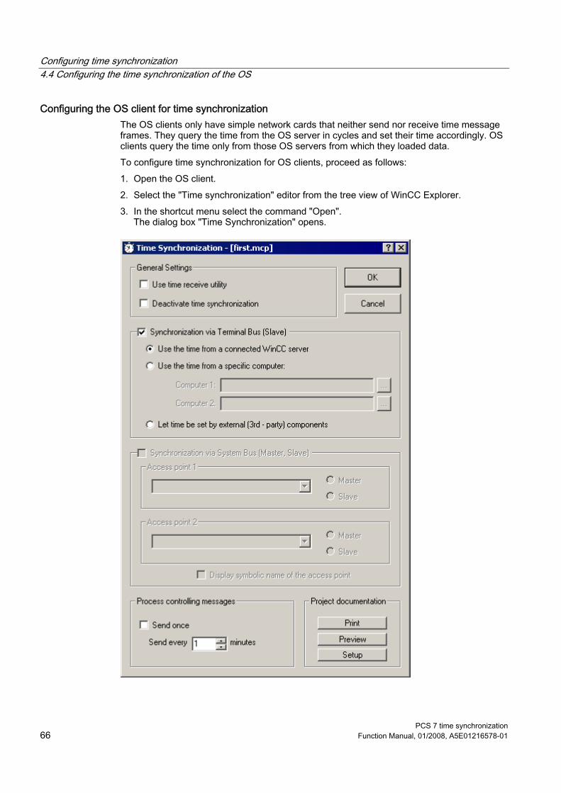
Configuring time synchronization 4.4 Configuring the time synchronization of the OS
PCS 7 time synchronization 66 Function Manual, 01/2008, A5E01216578-01
Configuring the OS client for time synchronization The OS clients only have simple network cards that neither send nor receive time message frames. They query the time from the OS server in cycles and set their time accordingly. OS clients query the time only from those OS servers from which they loaded data. To configure time synchronization for OS clients, proceed as follows: 1. Open the OS client. 2. Select the "Time synchronization" editor from the tree view of WinCC Explorer. 3. In the shortcut menu select the command "Open".
The dialog box "Time Synchronization" opens.

Configuring time synchronization 4.4 Configuring the time synchronization of the OS
PCS 7 time synchronization Function Manual, 01/2008, A5E01216578-01 67
4. Select the check box "Synchronization via terminal bus (slave)". Thus all associated check boxes and text boxes can be selected.
5. Select the "Use time from a connected WinCC server" check box. 6. Click "OK" to save your entries. Execute these steps for every OS client that will be synchronized.
Configure the time-of-day mode of the CP 1613 To configure time-of-day mode for the CP 1613, proceed as follows: 1. Open SIMATIC Manager. 2. Select the station that will be synchronized. 3. Open the configuration of the station. 4. Select the CP 1613 and select the "Object Properties" command in the "Edit" menu.
5. Open the "Options" tab and select the "Time-of-day mode" check box. 6. Click "OK".

Configuring time synchronization 4.4 Configuring the time synchronization of the OS
PCS 7 time synchronization 68 Function Manual, 01/2008, A5E01216578-01
Note Comply with the following instructions for the time synchronization settings on the OS: • We recommend assigning parameters to all OS servers as time master. • If you have configured on an engineering station, select the check box "Use symbolic
names". If this check box is not selected, only those installed cards of the ES will be displayed that are not naturally present on the OS. Symbolic names on the other hand are converted in runtime on the OS.
• To synchronize the time via the plant bus, configure a device via "Access point 1". In the following cases configure a second device via "Access point 2". – If you want to use a redundant device. – If you want to synchronize two plant busses via one "bridge". – If you want to synchronize two plant busses as master concurrently.
Note OS server in a domain Before you set the time synchronization parameters for a PCS 7 system in a Windows domain, create a detailed plan of your network structure. This plan must contain all the relevant information for time synchronization: • Which computer is the domain controller? • Which computers belong to the domain and receive the time from the domain
controller? • Which computers do not belong to the domain and where do they obtain their time
from? • Which computers are time masters and which are time slaves?

Configuring time synchronization 4.4 Configuring the time synchronization of the OS
PCS 7 time synchronization Function Manual, 01/2008, A5E01216578-01 69
4.4.3 How to set time synchronization on an OS in a domain without central time master
Basic configuration
Requirement ● All AS must be configured as time slaves. ● An NTP time server must be connected. ● The domain controller must be configured as the time master of the overall structure.
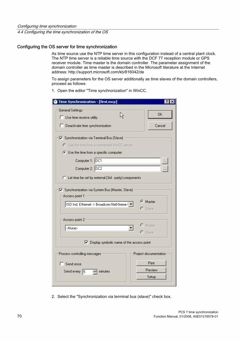
Configuring time synchronization 4.4 Configuring the time synchronization of the OS
PCS 7 time synchronization 70 Function Manual, 01/2008, A5E01216578-01
Configuring the OS server for time synchronization As time source use the NTP time server in this configuration instead of a central plant clock. The NTP time server is a reliable time source with the DCF 77 reception module or GPS receiver module. Time master is the domain controller. The parameter assignment of the domain controller as time master is described in the Microsoft literature at the Internet address: http://support.microsoft.com/kb/816042/de To assign parameters for the OS server additionally as time slaves of the domain controllers, proceed as follows: 1. Open the editor "Time synchronization" in WinCC.
2. Select the "Synchronization via terminal bus (slave)" check box.

Configuring time synchronization 4.4 Configuring the time synchronization of the OS
PCS 7 time synchronization Function Manual, 01/2008, A5E01216578-01 71
3. Select the "Accept time from permanently defined computer" check box and click the domain controller "Computer 1" that is parameter assigned as time master.
4. For "Computer2" select an additional domain controller as passive time master if desired. 5. Select the "Synchronization via plant bus (master, slave)" check box. 6. Select the check box "Display symbolic names of the access points". This will display the
communication modules of the OS server with symbolic names, if they are not available on the ES.
7. Select the CP under "Access point 1" for time synchronization parameters have been assigned, and select the "Master" check box. If you use a redundant CP, select the required CP for "Access point 2" and select the "Master" check box (default setting).

Configuring time synchronization 4.4 Configuring the time synchronization of the OS
PCS 7 time synchronization 72 Function Manual, 01/2008, A5E01216578-01
Configuring OS clients for time synchronization To configure time synchronization for the OS clients, proceed as follows: 1. Open the OS client. 2. Select the "Time synchronization" editor from the tree view of WinCC Explorer. 3. In the shortcut menu select the command "Open".
The dialog box "Time Synchronization" opens.
4. Select the "Synchronization via terminal bus (slave)" check box. 5. Select the "Use the time from a connected WinCC server" check box.

Configuring time synchronization 4.4 Configuring the time synchronization of the OS
PCS 7 time synchronization Function Manual, 01/2008, A5E01216578-01 73
6. Click "OK".
Result The coupling module will now receive and send time message frames. The OS servers are cooperative time masters. If a CP1613 does not receive a time signal, WinCC time synchronization switches to master mode. It will then send time signals for the failed time master as replacement.
Note The AS can only be synchronized if at least one OS server is activated. Instructions for configuring the domain controller are described in the Microsoft literature: "Configuring an authorized time server in Windows Server 2003" at the Internet Address http://support.microsoft.com/kb/816042/de
CAUTION If a time time jump of more than 5 seconds takes place on the OS server in the UTC, then the OS server configured as time master will no longer be used as time master. In addition the I&C system message "Time synchronization has been permanently deactivated" will be output. Note that also after a restart this server is no longer defined as time master. Reconfigure the OS server as time master and load the configuration on the OS server.

Configuring time synchronization 4.4 Configuring the time synchronization of the OS
PCS 7 time synchronization 74 Function Manual, 01/2008, A5E01216578-01
4.4.4 How to set time synchronization on an OS in a work group with central time master
Basic configuration
Requirement ● In the configuration console for the CP of the OS server the option "Time tracking" must
be selected. ● All AS are configured as time slaves (exception: CPU 416-3 PN/DP and CPU 414-3
PN/DP). ● The OS server is equipped with a CP1613 or with a BCE network card.

Configuring time synchronization 4.4 Configuring the time synchronization of the OS
PCS 7 time synchronization Function Manual, 01/2008, A5E01216578-01 75
Configuring the OS server for time synchronization To synchronize the OS server, proceed as follows: 1. Open the OS server. 2. Select the "Time synchronization" editor from the tree view of WinCC Explorer. 3. In the shortcut menu select the command "Open".
The dialog box "Time Synchronization" opens.
4. Select the "Synchronization via plant bus (master, slave)" check box.

Configuring time synchronization 4.4 Configuring the time synchronization of the OS
PCS 7 time synchronization 76 Function Manual, 01/2008, A5E01216578-01
5. From the "Access point 1" drop-down list box select the CP for which you have clicked time synchronization in the configuration console. The list shows all devices installed on the computer that are suitable for time synchronization.
6. Select the "Master" option button. 7. If you use a redundant CP, select the required CP under "Access point 2", 8. Select the "Master" option button. 9. Click "OK".
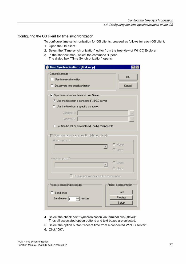
Configuring time synchronization 4.4 Configuring the time synchronization of the OS
PCS 7 time synchronization Function Manual, 01/2008, A5E01216578-01 77
Configuring the OS client for time synchronization To configure time synchronization for OS clients, proceed as follows for each OS client: 1. Open the OS client. 2. Select the "Time synchronization" editor from the tree view of WinCC Explorer. 3. In the shortcut menu select the command "Open".
The dialog box "Time Synchronization" opens.
4. Select the check box "Synchronization via terminal bus (slave)". Thus all associated option buttons and text boxes are selected.
5. Select the option button "Accept time from a connected WinCC server". 6. Click "OK".

Configuring time synchronization 4.4 Configuring the time synchronization of the OS
PCS 7 time synchronization 78 Function Manual, 01/2008, A5E01216578-01
4.4.5 How to set time synchronization on an OS in a work group without central master
Basic configuration
Requirement ● OS server must be time master on the plant bus ● All AS must be configured as time slaves ● Restriction: CPU 416-3- PN/DP and CPU 414-3 PN/DP cannot be used in this
configuration (synchronization lacking).

Configuring time synchronization 4.4 Configuring the time synchronization of the OS
PCS 7 time synchronization Function Manual, 01/2008, A5E01216578-01 79
Setting the terminal bus To configure time synchronization for the terminal bus, proceed as follows: 1. Open the editor "Time synchronization" in WinCC Explorer.
2. Select the "Synchronization via terminal bus (slave)" check box. 3. Select the check box "Use the time from a specific computer" and enter the name of the
computer with the DCF/GPS receiver under "Computer 1". 4. Select the "Synchronization via plant bus (master, slave)" check box. 5. Select the option button "Display symbolic names of the access points".
Configuring time synchronization 4.4 Configuring the time synchronization of the OS
PCS 7 time synchronization 80 Function Manual, 01/2008, A5E01216578-01
6. Select "CP1613" as access point 1 and click the "Master" check box. 7. Select "<none>" as access point 2. 8. Select "Every 5 minutes" for triggering the I&C system message. 9. Click "OK".
Result The coupling module can now send and receive time messages. The OS servers are cooperative time masters. If a CP1613 does not receive a time signal on the plant bus, WinCC time synchronization switches to master mode. It will then send time signals for the failed time master as replacement.
CAUTION If a time jump of more than 5 seconds occurs, the computer defined as the time master becomes a time slave. The message "Time synchronization has been permanently switched to slave" is generated. Note that also after a restart this computer is no longer defined as time master. Reconfigure the computer as time master and load the configuration on the computer.
4.4.6 How to set the OS server for reception of time service via DCF77RS
Requirement ● In the Control Panel the COM interface must be set for the DCF 77 receiver. ● The extended FIFO setting must be switched off. ● The DCF 77 reception service must be installed, parameters must have been assigned,
and it must have been started. You can find additional information about installing the DCF 77 reception service in the section "Configuring DCF 77 reception service for Windows."
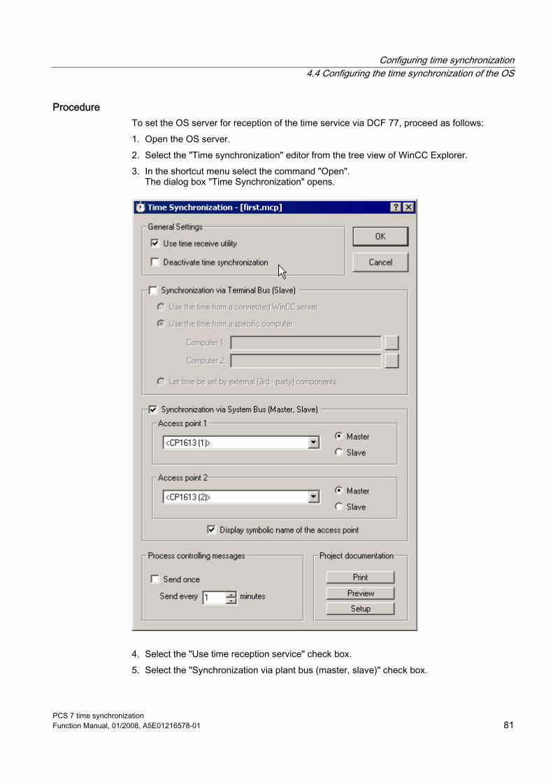
Configuring time synchronization 4.4 Configuring the time synchronization of the OS
PCS 7 time synchronization Function Manual, 01/2008, A5E01216578-01 81
Procedure To set the OS server for reception of the time service via DCF 77, proceed as follows: 1. Open the OS server. 2. Select the "Time synchronization" editor from the tree view of WinCC Explorer. 3. In the shortcut menu select the command "Open".
The dialog box "Time Synchronization" opens.
4. Select the "Use time reception service" check box. 5. Select the "Synchronization via plant bus (master, slave)" check box.
Configuring time synchronization 4.4 Configuring the time synchronization of the OS
PCS 7 time synchronization 82 Function Manual, 01/2008, A5E01216578-01
6. From the "Access point 1" list select the CP for which you have clicked time synchronization in the configuration console. Here all CP are displayed that are available in the OS server.
7. Select the "Master" option button. 8. If you use a redundant CP, select the required CP for "Access point 2", 9. Select the "Master" option button. 10. Click "OK".
See also Configuring DCF 77 reception service for Windows (Page 53)

Configuring time synchronization 4.5 Configuring time synchronization on an AS
PCS 7 time synchronization Function Manual, 01/2008, A5E01216578-01 83
4.5 Configuring time synchronization on an AS
4.5.1 How to set time synchronization on an AS for SIMATIC mode
Requirement ● An AS with one of the CP 443-1, 443-5 Extended capable of time synchronization is
used. ● A CPU capable of time synchronization is used for the SIMATIC mode. ● Time master is an external time sender
Setting the CPU To configure time synchronization for the CPU, proceed as follows: 1. Open the project in SIMATIC Manager. 2. Select the station that will be synchronized. 3. Open the configuration of the hardware. 4. Select the CPU and select the "Object Properties" command in the "Edit" menu.
The "CPU Properties" dialog box opens.

Configuring time synchronization 4.5 Configuring time synchronization on an AS
PCS 7 time synchronization 84 Function Manual, 01/2008, A5E01216578-01
5. Go to the "Diagnostics/Clock" tab.
6. In the "Clock" group select the following: – For "Synchronization in the AS" select the synchronization mode, "As slave". – For "Synchronization to MPI" select the synchronization type "None"
7. Click "OK".
Result The AS is configured as time slave for time synchronization.

Configuring time synchronization 4.5 Configuring time synchronization on an AS
PCS 7 time synchronization Function Manual, 01/2008, A5E01216578-01 85
Setting CP 443-1 (Industrial Ethernet) To configure time synchronization for the CP443-1, proceed as follows: 1. Open the project in SIMATIC Manager. 2. Select the station that will be synchronized. 3. Open the configuration of the hardware. 4. Select CP 443-1 and select the "Object Properties" command in the "Edit" menu. 5. Go to the "Time synchronization" tab and select the check box "Enable time-of-day
synchronization in SIMATIC mode".
Note These settings are in the "Options" tab under "Switch on time synchronization" for older CP443-1 (<EX11).
6. Click "OK". If you have multiple stations repeat this procedure for each CP.
Result The communications processor uses the SIMATIC mode for time synchronization.

Configuring time synchronization 4.5 Configuring time synchronization on an AS
PCS 7 time synchronization 86 Function Manual, 01/2008, A5E01216578-01
Note for redundant systems If in a SIMATIC H-station (high-availability process control systems) multiple CPs are present that are connected to the same network, then time synchronization can only be switched on for one of these CPs. The following table shows the possible arrangement:
Plant bus CPU 1/rack 1 CPU 2/rack 2 Plant bus 1 CP 1/1 Time synchronization
enabled CP 1/2 Time synchronization
disabled Plant bus 2 CP 1/2 Time synchronization
disabled CP 2/2 Time synchronization
enabled
Setting CP 443-5 Extended (PROFIBUS DP) To configure time synchronization for the CP443-5 Extended, proceed as follows: 1. Open the project in SIMATIC Manager. 2. Select the station that will be synchronized. 3. Open the configuration of the hardware. 4. Select CP 443-5 Extended and select the "Object Properties" command in the "Edit"
menu.

Configuring time synchronization 4.5 Configuring time synchronization on an AS
PCS 7 time synchronization Function Manual, 01/2008, A5E01216578-01 87
5. Go to the tab "Mode" and select the "DP master" option button.

Configuring time synchronization 4.5 Configuring time synchronization on an AS
PCS 7 time synchronization 88 Function Manual, 01/2008, A5E01216578-01
6. Go to the "Options" tab and select the option button "From station to LAN" in the area "Time synchronization" "Forward time message frames".
7. Click "OK".

Configuring time synchronization 4.5 Configuring time synchronization on an AS
PCS 7 time synchronization Function Manual, 01/2008, A5E01216578-01 89
Result The time message frames of the time master will be forwarded to the AS on the plant bus.
Note Please note the following: • The CPUs 414-3 PN/DP (6ES7416-3ER05-0AB0) and 416-3 PN/DP (6ES7414-3EM05-
0AB0) can only be synchronized using the NTP mode. We recommend a SICLOCK TM that supports a maximum of 50 NTP requests as external clock. These CPUs can only be used in PCS 7 configurations with a plant bus and a terminal bus (see section "How to set time synchronization on an AS for NTP mode").
• For all other CPUs we recommend that you continue to use the SIMATIC mode.
See also How to set time synchronization on an AS for NTP mode (Page 90)

Configuring time synchronization 4.5 Configuring time synchronization on an AS
PCS 7 time synchronization 90 Function Manual, 01/2008, A5E01216578-01
4.5.2 How to set time synchronization on an AS for NTP mode
Requirement ● A CPU 416-3 PN/DP or a CPU 414-3 PN/DP are used.
Setting the CPU CPU 416-3 PN-IO and CPU 414-3 PN-IO have an on-board Ethernet port and are therefore configured for NTP mode. To configure time synchronization for the CPU, proceed as follows: 1. Open the project in SIMATIC Manager. 2. Select the station that will be synchronized. 3. Open the configuration of the hardware. 4. Select the CPU and select the "Object Properties" command in the "Edit" menu.
The "CPU Properties" dialog box opens. 5. Go to the "Diagnostics/Clock" tab.
6. In the "Clock" group select the following:
– Synchronization method "As master" and a time interval of "10 seconds" for "in AS" synchronization
– Synchronization method "None" for "on MPI" synchronization 7. Click "OK".

Configuring time synchronization 4.5 Configuring time synchronization on an AS
PCS 7 time synchronization Function Manual, 01/2008, A5E01216578-01 91
Result The AS is configured as time master for time synchronization.
Setting PN IO To configure the PN IO interface for time synchronization, proceed as follows: 1. Open the project in SIMATIC Manager. 2. Select the station that will be synchronized. 3. Open the configuration of the hardware. 4. Select the PN IO interface and select the "Object Properties" command in the "Edit"
menu. 5. Open the "Time synchronization" tab and select the check box "Enable time-of-day
synchronization in NTP mode" in the "NTP Mode" area.
6. Enter the IP address of SICLOCK TM as the NTP server address. 7. Enter "10" as the activation interval (seconds). 8. Click "OK".
Result The PN IO interface is used for time synchronization for the NTP mode.

Configuring time synchronization 4.6 Configuring time synchronization for SIMATIC BATCH
PCS 7 time synchronization 92 Function Manual, 01/2008, A5E01216578-01
4.6 Configuring time synchronization for SIMATIC BATCH
4.6.1 Overview of configuration steps
Configuration steps Use SIMATIC BATCH to plan, control, and log batch processes. Time synchronization of the complete plant is particularly important for these processes. SIMATIC BATCH runs alone or together with the operator station on a PC. The following table shows which configuration steps are necessary to synchronize the processes from SIMATIC BATCH:
Step Configuration steps 1 Install DCF 77 client 2 Configure DCF 77 client
4.6.2 How to set time synchronization on a BATCH station
Introduction If SIMATIC BATCH is running on a PCS 7 PC that does not have WinCC time synchronization, this PC will be synchronized via the "DCF 77 Client" software to be installed. You will find the DCF 77 client on the toolset DVD in the "Additional Products" folder.
Requirement ● The DCF77 client must be installed.
Additional information on installing the DCF 77 installation client is available in the section "Configuring DCF 77 reception service".

Configuring time synchronization 4.6 Configuring time synchronization for SIMATIC BATCH
PCS 7 time synchronization Function Manual, 01/2008, A5E01216578-01 93
Procedure To configure time synchronization on a SIMATIC BATCH station, proceed as follows: 1. Open the DCF 77 reception service from the menu "Start > Settings > Control Panel".
This opens the "DCF77 reception service" dialog box.

Configuring time synchronization 4.6 Configuring time synchronization for SIMATIC BATCH
PCS 7 time synchronization 94 Function Manual, 01/2008, A5E01216578-01
2. Under "Connection" select the server that is configured as time master.
3. Click "OK".
4.6.3 How to set time synchronization on a BATCH/operator station
Procedure If SIMATIC BATCH is installed on the operator station, it will be synchronized via the WinCC time synchronization.
See also Configuring the time synchronization of the OS (Page 62)

Configuring time synchronization 4.7 Configuring time synchronization for SIMATIC Route Control
PCS 7 time synchronization Function Manual, 01/2008, A5E01216578-01 95
4.7 Configuring time synchronization for SIMATIC Route Control
4.7.1 Overview of configuration steps
Configuration steps Time synchronization of the complete plant is particularly important for SIMATIC Route Control processes. SIMATIC Route Control runs alone or together with the operator station on a PC. The following table shows which configuration steps are necessary to synchronize the processes of SIMATIC Route Control:
Step Configuration steps 1 Install DCF 77 client 2 Configure DCF 77 client
4.7.2 How to set time synchronization on a Route Control station
Introduction If SIMATIC Route Control is running on a PCS 7 PC that does not have WinCC time synchronization, this PC will be synchronized via the "DCF 77 Client" software to be installed. You can find the "DCF 77 Client" software on the toolset DVD in the "Additional Products" folder.
Requirement ● The DCF 77 client must be installed. Additional information on installation of the DCF 77 client is provided in the section "Configuring DCF 77 reception service.

Configuring time synchronization 4.7 Configuring time synchronization for SIMATIC Route Control
PCS 7 time synchronization 96 Function Manual, 01/2008, A5E01216578-01
Procedure To configure time synchronization for the Route Control station, proceed as follows: 1. Open the DCF 77 reception service from the menu "Start > Settings > Control Panel".
This opens the "DCF77 reception service" dialog box.

Configuring time synchronization 4.7 Configuring time synchronization for SIMATIC Route Control
PCS 7 time synchronization Function Manual, 01/2008, A5E01216578-01 97
2. Under "Connection" select the server that is configured as time master.
3. Click "OK".
4.7.3 How to set time synchronization on a route control/operator station.
Procedure If SIMATIC Route Control is installed on the operator station, it will be synchronized via the WinCC time synchronization. The procedure for this is described in the section "Configuring time synchronization of the OS".
See also Configuring the time synchronization of the OS (Page 62)

Configuring time synchronization 4.8 How to set the time synchronization for SIMATIC BOX
PCS 7 time synchronization 98 Function Manual, 01/2008, A5E01216578-01
4.8 How to set the time synchronization for SIMATIC BOX
Introduction A connected clock is not provided for PCS 7 Box as a standalone system and with swapped out engineering. The time is only synchronized with WinCC from the PC clock. The following procedure refers to the time synchronization of the SIMATIC BOX in the PCS 7 network.
Synchronize the time of the AS through the plant bus You can synchronize the CPU in the SIMATIC PCS 7 BOX station along with other network nodes in the PCS 7 network via the plant bus using a central time master, such as SICLOCK TM. The time master provides the time of day in cyclic intervals on the Industrial Ethernet/PROFIBUS. For Industrial Ethernet only the ISO protocol is supported.
Requirement ● A time master such as SICLOCK TM must be integrated in the plant bus. ● The on-board Ethernet network interface of the SIMATIC PCS 7 BOX station must be
connected to the plant bus of the PCS 7 system. This interface card must be capable of processing the time signal of the time master.
● WinAC must be installed. ● In HW Config, "As slave" must be set as the synchronization mode for the time
synchronization in the AS.
Procedure To synchronize the time of the AS via the plant bus, proceed as follows: 1. In the menu "Start > SIMATIC > PC Based Control" select the command "WinAC time
synchronization". For SIMATIC PCS 7 BOX 416 the dialog box "CPU 41x-2 PCI time synchronization" is opened. For SIMATIC PCS 7 BOX RTX the dialog box "WinLC time synchronization" is opened.
2. In the "Settings" group under "Source", click "CP". 3. Click "Select". 4. In the subsequently displayed "Set PG/PC Interface" dialog box, select the interface
connected to the plant bus under the "Interface Parameter Assignment in the PG/PC" group.
5. Then, click "OK" to close the dialog box. 6. Click "OK" to confirm the displayed message. 7. Click "Start" to start the time synchronization. 8. Click "Close" to close the dialog box.

Configuring time synchronization 4.8 How to set the time synchronization for SIMATIC BOX
PCS 7 time synchronization Function Manual, 01/2008, A5E01216578-01 99
Synchronize the time of the OS through the plant bus You can synchronize the CPU in the SIMATIC PCS 7 BOX station along with other network nodes in the PCS 7 network via the plant bus using a central time master, such as SICLOCK TM.
Requirement ● A time master such as SICLOCK TM must be integrated in the plant bus. ● The WinCC project on the ES in the PCS 7 network must be opened.
Procedure To synchronize the time of the OS via the plant bus, proceed as follows: 1. Open the editor "Time synchronization" in WinCC. 2. Select the "Synchronization via the plant bus (master, slave)" check box. 3. Select the check box "Display symbolic names of the access points". 4. Under "Access point 1" select "<Softnet(1)>" via which the time will be synchronized on
the plant bus. Select the "Slave" option button because SICLOCK TM is time master. 5. Click "OK."

Configuring time synchronization 4.9 How to set time synchronization on the engineering station
PCS 7 time synchronization 100 Function Manual, 01/2008, A5E01216578-01
4.9 How to set time synchronization on the engineering station
Introduction The PCS 7 Engineering Station does not have WinCC time synchronization. It is synchronized via the "DCF 77 Client" software that also must be installed. Thus correct logging of messages is ensured. If time synchronization via DCF 77 fails, the ES in a domain still receives a time signal every 8 hours via a connected domain controller.
Requirement ● The "DCF 77 Client" software must be installed.
You can find additional information about installing the "DCF 77 Client" software under "Configuring DCF 77 reception service for Windows."

Configuring time synchronization 4.9 How to set time synchronization on the engineering station
PCS 7 time synchronization Function Manual, 01/2008, A5E01216578-01 101
Procedure To synchronize the time on the engineering station, proceed as follows: 1. Open the DCF 77 reception service from the menu "Start > Settings > Control Panel".
This opens the "DCF77 reception service" dialog box.

Configuring time synchronization 4.9 How to set time synchronization on the engineering station
PCS 7 time synchronization 102 Function Manual, 01/2008, A5E01216578-01
2. Under "Connection" select the server that is configured as time master.
3. Click "OK".

Configuring time synchronization 4.10 Configuring redundant PCS 7 systems
PCS 7 time synchronization Function Manual, 01/2008, A5E01216578-01 103
4.10 Configuring redundant PCS 7 systems
4.10.1 How to configure time synchronization of OS servers with redundant CP 1613 and an external clock
Introduction The described configuration is based on redundant OS servers on a redundant plant bus.
Requirement ● Each of the two OS servers has two CP 1613. ● Timer is SICLOCK TM. ● WinCC is opened on one of the OS servers.
Procedure To synchronize the time on a redundant OS with external clock, follow these steps: 1. In WinCC Explorer, select the menu command Editor > Time Synchronization > Open.
The "Time Synchronization" dialog box opens. 2. Select the "Synchronization via plant bus (master, slave)" check box. 3. From the "Access point 1" list select the CP for which you have clicked time
synchronization in the configuration console. The list shows all installed devices that are suitable for time synchronization.
4. Select the "Master" option button. This defines the OS server as time master.
5. For "Access point 2" select the required redundant CP and activate the "Master" option button. This specifies a redundant time synchronization which implements the connection to the plant bus on failure of the first CP.
6. Click "OK" to save your entries.

Configuring time synchronization 4.10 Configuring redundant PCS 7 systems
PCS 7 time synchronization 104 Function Manual, 01/2008, A5E01216578-01
4.10.2 How to configure time synchronization on a PCS 7 system with redundant bus system
Configuration steps The following table shows the configuration steps that are necessary to configure the time synchronization for redundant buses:
Step Procedure See chapter 1 Assign parameters for the SICLOCK "Configuring SICLOCK TM" 2 Connect GPS to SICLOCK and configure "Configuring GPS" 3 Assign the DCF 77 reception service parameters on the
domain controller • Installing and configuring "DCF 77 reception service
for Windows" • Port/interface: COM1 or COM2 • Time Base: Local Time
"Configuring "DCF77 reception service for Windows"
4 Connect SICLOCK to the plant bus depending on the selected configuration: • Via Ethernet for high-availability redundant buses • Via SCALANCE for separated plant buses
"Network environment of a PCS 7 system"
5 Configuring time synchronization in HW Config "How to set time synchronization on an AS".
6 Assign parameters for OS servers with WinCC time synchronization
"Configuring the time synchronization of the OS"
7 Assign parameters for OS client with WinCC time synchronization
"Configuring the time synchronization of the OS"
The description of the required configuration steps is in the specified chapters.

Configuring time synchronization 4.11 Protecting the network from undesired external synchronization
PCS 7 time synchronization Function Manual, 01/2008, A5E01216578-01 105
4.11 Protecting the network from undesired external synchronization
4.11.1 Overview of necessary settings
Introduction If you operate multiple plants in one corporate network, the plants should not receive any time message frames from the corporate network.
Method Connect the corporate network and the plants via a router. Configure the router in such a manner that forwarding of time message frames is blocked.
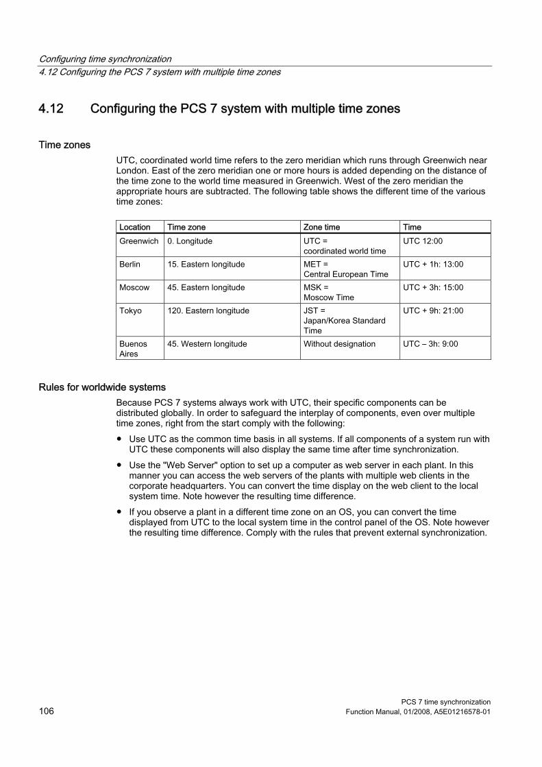
Configuring time synchronization 4.12 Configuring the PCS 7 system with multiple time zones
PCS 7 time synchronization 106 Function Manual, 01/2008, A5E01216578-01
4.12 Configuring the PCS 7 system with multiple time zones
Time zones UTC, coordinated world time refers to the zero meridian which runs through Greenwich near London. East of the zero meridian one or more hours is added depending on the distance of the time zone to the world time measured in Greenwich. West of the zero meridian the appropriate hours are subtracted. The following table shows the different time of the various time zones:
Location Time zone Zone time Time Greenwich 0. Longitude UTC =
coordinated world time UTC 12:00
Berlin 15. Eastern longitude MET = Central European Time
UTC + 1h: 13:00
Moscow 45. Eastern longitude MSK = Moscow Time
UTC + 3h: 15:00
Tokyo 120. Eastern longitude JST = Japan/Korea Standard Time
UTC + 9h: 21:00
Buenos Aires
45. Western longitude Without designation UTC – 3h: 9:00
Rules for worldwide systems Because PCS 7 systems always work with UTC, their specific components can be distributed globally. In order to safeguard the interplay of components, even over multiple time zones, right from the start comply with the following: ● Use UTC as the common time basis in all systems. If all components of a system run with
UTC these components will also display the same time after time synchronization. ● Use the "Web Server" option to set up a computer as web server in each plant. In this
manner you can access the web servers of the plants with multiple web clients in the corporate headquarters. You can convert the time display on the web client to the local system time. Note however the resulting time difference.
● If you observe a plant in a different time zone on an OS, you can convert the time displayed from UTC to the local system time in the control panel of the OS. Note however the resulting time difference. Comply with the rules that prevent external synchronization.

Configuring time synchronization 4.13 Time synchronization of multiple systems with autonomous internal timers
PCS 7 time synchronization Function Manual, 01/2008, A5E01216578-01 107
4.13 Time synchronization of multiple systems with autonomous internal timers
Note If you synchronize multiple plants with only one timer only the time message frame should be transmitted to the plants. For this purpose use a switch with port lock function, e.g. the SCALANCE X414-3E. Connect the clocks and the plants to the switch. If port lock is selected, bidirectional communication is not possible. In this manner only the SIMATIC time message frame is transmitted on the plant bus; no other data is transmitted on the plant bus. To find additional information, use the following links: ● http://www.siemens-edm.de/siclock.0.html ● http://siemens-edm.de/fileadmin/Application_Notes/App_Notes_0002.pdf

Configuring time synchronization 4.13 Time synchronization of multiple systems with autonomous internal timers
PCS 7 time synchronization 108 Function Manual, 01/2008, A5E01216578-01

PCS 7 time synchronization Function Manual, 01/2008, A5E01216578-01 109
Appendix A AA.1 Script "GetTimeFromPC"
Programming code "GetTimeFromPC" Use the following script to allow time to be output within a diagnostic display in an I/O field:
//---------------------------------------------------------------------------- // This function reads time from a specified computer ("\\PcName"). // Don't forget that in string literals you must write it like"\\\\PcName". // // Result is a string of the format "dd:mm:yyyy hh:mm:ss.msc" // // Warning: If the specified computer is not reachable, the call to // NetRemotetime hangs a few seconds and blocks scripting! //---------------------------------------------------------------------------- BOOL GetTimeFromPC(const char* pszComputerName, char* pszResultBuffer, int nResultBufferSize) { typedef struct _TIME_OF_DAY_INFO { DWORD time_elapsedt; DWORD time_msecs; DWORD time_hours; DWORD time_mins; DWORD time_secs; DWORD time_hunds; LONG time_timezone; DWORD time_tinterval; DWORD time_day; DWORD time_month; DWORD time_year; DWORD time_weekday; } TIME_OF_DAY_INFO; WCHAR wszUncName[(MAX_COMPUTERNAME_LENGTH + 1) * 2]; DWORD dwResult = 0; char szResult[100] = ""; TIME_OF_DAY_INFO* ptimeInfo = NULL; #pragma code ("netapi32.dll"); DWORD NetRemotetime(LPWSTR UncServerName, LPBYTE *BufferPtr); DWORD NetApiBufferFree(LPVOID Buffer); #pragma code() #pragma code ("kernel32.dll"); int MultiByteToWideChar( UINT CodePage, // code page DWORD dwFlags, // character-type options

Appendix A A.1 Script "GetTimeFromPC"
PCS 7 time synchronization 110 Function Manual, 01/2008, A5E01216578-01
LPCSTR lpMultiByteStr, // string to map int cbMultiByte, // number of bytes in string LPWSTR lpWideCharStr, // wide-character buffer int cchWideChar // size of buffer ); #pragma code() memset(wszUncName, 0, sizeof(wszUncName)); MultiByteToWideChar(0, 0, pszComputerName, -1, wszUncName, MAX_COMPUTERNAME_LENGTH + 1); dwResult = NetRemotetime(wszUncName, (LPBYTE*)&ptimeInfo); if(0 == dwResult) sprintf(szResult, "%02d.%02d.%04d %02d:%02d:%02d.%03d", ptimeInfo->time_day, ptimeInfo->time_month, ptimeInfo->time_year, ptimeInfo->time_hours, ptimeInfo->time_mins, ptimeInfo->time_secs, ptimeInfo->time_hunds * 10); else sprintf(szResult, "<error: %d>", dwResult); if(nResultBufferSize > strlen(szResult)) strcpy(pszResultBuffer, szResult); else dwResult = 1; // buffer too small if(ptimeInfo != NULL) NetApiBufferFree(ptimeInfo); return (dwResult == 0); }
PCS 7 time synchronization Function Manual, 01/2008, A5E01216578-01 111
Glossary
Active time master The active time master sends the time signal to the time slaves and to the passive time masters.
CEDST Central European Daylight Saving Time
Central plant clock An central plant clock receives a time signal from an external clock and forwards it to the terminal bus or the plant bus.
CET Central European Time
Clock, external External clocks synchronize a plant with the aid of externally received time signals, e.g. the radio signal DCF77 or the satellite based GPS signal.
Cooperative time master A cooperative time master takes over the role of time master only when it no longer receives time signals from the active time master.
DCF77 Radio reception of the atomic clock in Braunschweig for operation in central Europe
Domain controller A domain controller is a server that regulates and manages the authentication and authorization of the computers and users.
GMT Greenwich Mean Time

Glossary
PCS 7 time synchronization 112 Function Manual, 01/2008, A5E01216578-01
GPS Global Positioning System
Local time The local time is actual time in the respective time zone.
Passive time master A passive time master takes over the function of the active time master if the active time master should fail.
RTC (Real Clock Time, hardware clock) RTC is the internal, battery-operated clock of a PC. This clock continues to run even if the PC is switched off and it has the precision of a quartz clock.
Stratum, strata A stratum is a hierarchy level within a structure of time servers. The stratum indicates the following with a number: ● The distance from the time source ● Which time servers are located on the same hierarchy level
Time master The time master is responsible for distributing the time signal within time synchronization. It forwards the time signal to the PCS7 components that have been configured as time slaves. The following time master types exist: ● Active time master ● Cooperative time master ● Passive time master
Time server A time server is a server that receives a time synchronization time and/or forwards it.
Time slave The time slaves are PCS 7 components that receive time signals from the time master and thus set their own clock.
Glossary
PCS 7 time synchronization Function Manual, 01/2008, A5E01216578-01 113
Time synchronization With time synchronization data and time of all time-dependent components are unified by a time master.
UTC (Universal Time Coordinated) UTC is a time basis specified by atomic clocks. It does not take daylight saving time into account.

Glossary
PCS 7 time synchronization 114 Function Manual, 01/2008, A5E01216578-01

PCS 7 time synchronization Function Manual, 01/2008, A5E01216578-01 115
Index
A Activating
DCF 77 receivers, 54 GPS receiver, 58
Aligning Antenna DCF 77, 55 GPS antenna, 59
Antenna DCF 77 Aligning, 55
Applications Time synchronization, 11
AS Configuring, 83
AS for NTP mode Configuring, 90
Avoiding External synchronization, 105
B Bus, redundant
Configuring, 104
C checking
Time, 21 Clocks
External, 27 Internal, 27
Commissioning Setting the DCF 77 reception service, 55
Configuration Domain, 36 Domain with central time master, 41 Domains with multiple hierarchies, 46 Time synchronization without central time master, 44 Work group, 35 Work group with central time master, 37 Work group without central time master, 39
Configurations Recommended, 35
Configuring AS, 83 AS for NTP mode, 90 Engineering system, 101 Multiple plants with an autonomous timer, 61 OS Client, 66 OS client in work group with central time master, 77 OS in work group with central time master, 75 OS server in domain, 64 PN IO, 91 Redundant bus, 104 Redundant OS servers with external timer, 103 Route Control, 96 Route Control/operator station, 97 Separate plant busses with SICLOCK TM/TS, 60 SIMATIC BATCH, 93 SIMATIC BATCH/operator station, 94 SIMATIC BOX, 98
Configuring for reception of time service OS server, 81
D Daylight saving time, 15
Setting on OS, 19 DCF 77 receivers, 53
Activating, 54 Installing, 54
DCF 77 reception service Set for commissioning, 55 Setting, 56
Definition Stratum, 24 Time synchronization, 13
Documentation Organization, 3 Purpose, 3 Target group, 4

Index
PCS 7 time synchronization 116 Function Manual, 01/2008, A5E01216578-01
Domain Configuration, 36 Time synchronization, 30
Domain with central time master Configuration, 41
Domains with multiple hierarchies Configuration, 46
E Engineering system
Configuring, 101 External
Clocks, 27 External synchronization
Avoiding, 105
G GPS antenna
Aligning, 59 GPS receiver
Activating, 58 Installing, 58
I Installing
DCF 77 receivers, 54 GPS receiver, 58
Internal Clocks, 27
L Local time, 15, 16
M Multiple plants with an autonomous timer
Configuring, 61
N NTP mode
SICLOCK, 52
O Organization
Documentation, 3 OS
Converting to daylight saving time, 19 Converting to local time, 17
OS Client Configuring, 66
OS client in work group with central time master Configuring, 77
OS in work group with central time master Configuring, 75
OS server Configuring for reception of time service, 81
OS server in domain Configuring, 64
P PCS 7 plant
Structure, 23 Plant busses, separated
Time synchronization, 33 plants with autonomous internal clocks
Synchronizing, 107 PN IO
Configuring, 91 Purpose
Documentation, 3
R Redundancy, 104
Time synchronization, 28, 32 Redundant OS servers with external timer
Configuring, 103 Route Control
Configuring, 96 Route Control/operator station
Configuring, 97 Rules
Structure - PCS 7 plant, 25 Systems over multiple time zones, 106

Index
PCS 7 time synchronization Function Manual, 01/2008, A5E01216578-01 117
S Script "GetTimeFromPC", 109 Selection
Time master, 47 Separate plant busses
Configuring with SICLOCK TM/TS, 60 Setting
Local time on the OS, 17 Setting the DCF 77 reception service, 56
SICLOCK NTP mode, 52 SIMATIC mode, 51
SICLOCK GPS, 57 Wiring, 58
SICLOCK TM, 50 SIMATIC BATCH
Configuring, 93 SIMATIC BATCH/operator station
Configuring, 94 SIMATIC BOX
Configuring, 98 SIMATIC mode
SICLOCK, 51 Skills, required, 4 Standard time, 15 Stratum
Definition, 24 Structure
PCS 7 plant, 23 Structure - PCS 7 plant
Rules, 25 Synchronizing
Synchronizing multiple systems with autonomous internal clocks, 107
Systems over multiple time zones Rules, 106
T Target group
Documentation, 4 time
Checking, 21 Time master, 26
Selection, 47 Time slave, 27 Time synchronization
Applications, 11 Definition, 13 in domain, 30 in the work group, 31 On separated plant busses, 33 Redundancy, 28, 32 V5, 14
Time synchronization without central time master Configuration, 44
V V5
Time synchronization, 14 Validity, 4
W Wiring
SICLOCK GPS, 58 Work group
Configuration, 35 Time synchronization, 31
Work group with central time master Configuration, 37
Work group without central time master Configuration, 39

PCS 7 time synchronization Function Manual, 01/2008, A5E01216578-01 118