SIMATIC PC RI25 P - Industry Support Siemens
62
English PC RI25 P Manual SIMATIC C79000-G7076-C798 Edition 02
Transcript of SIMATIC PC RI25 P - Industry Support Siemens
English
PC RI25 P
Manual
SIMATIC
C79000-G7076-C798
Edition 02

This manual contains notices which you should observe to ensure your own personalsafety, as well as to protect the product and connected equipment. These notices arehighlighted in the manual by a warning triangle and are marked as follows according tothe level of danger:
!Warningindicates that death, severe personal injury or substantial property damage can resultif proper precautions are not taken.
Note
draws your attention to particularly important information on the product, handlingthe product, or to a particular part of the documentation.
The device/system may only be set up and operated in conjunction with this manual.
Only qualified personnel should be allowed to install and work on this equipment.Qualified persons are defined as persons who are authorized to commission, to ground,and to tag circuits, equipment, and systems in accordance with established safetypractices and standards.
Note the following:
!WarningThis device and its components may only be used for the applications described in thecatalog or the technical description, and only in connection with devices or componentsfrom other manufacturers which have been approved or recommended by Siemens.
This product can only function correctly and safely if it is transported, stored, set up, andinstalled correctly, and operated and maintained as recommended.
SIMATIC� SIMATIC HMI� and SIMATIC NET� are registered trademarks ofSIEMENS AG.
Third parties using for their own purposes any other names in this document which referto trademarks might infringe upon the rights of the trademark owners.
Copyright � Siemens AG 1998 All Rights Reserved
The reproduction, transmission or use of this document or its contents is notpermitted without express written authority. Offenders will be liable for damages.All rights, including rights created by patent grant or registration of a utility modelor design, are reserved.
C79000-G7076-C798
Siemens AGBereich Automatisierungs- und AntriebstechnikGeschaeftsgebiet Industrie-AutomatisierungssystemePostfach 4848, D-90327 NürnbergSiemens Aktiengesellschaft
Disclaimer of Liability
We have checked the contents of this manual for agreement with the hardwareand software described. Since deviations cannot be precluded entirely, we cannotguarantee full agreement. However, the data in this manual are reviewedregularly and any necessary corrections included in subsequent editions.Suggestions for improvement are welcomed.
� Siemens AG 1998Technical data subject to change.
Safety Guidelines
Qualified Personnel
Correct Usage
Trademarks
이 기기는 업무용(A급) 전자파 적합기기로서 판매자 또는 사용자는 이 점을 주의하시기 바라며 가정 외의 지역에서 사용하는 것을 목적으로 합니다.

English
iiiSIMATIC PCC79000-G7076-C798-02
Contents
1 Safety Instructions 1-1. . . . . . . . . . . . . . . . . . . . . . . . . . . . . . . . . . . . .
1.1 General Notes 1-1. . . . . . . . . . . . . . . . . . . . . . . . . . . . . . . . .
1.2 Information Regarding the CE Label 1-5. . . . . . . . . . . . . .
1.3 Approvals for the USA and Canada 1-6. . . . . . . . . . . . . . .
1.4 Technical Specifications 1-8. . . . . . . . . . . . . . . . . . . . . . . . .
2 Starting Up Your PC 2-1. . . . . . . . . . . . . . . . . . . . . . . . . . . . . . . . . . . .
2.1 Unpacking and Checking the Delivery Contents 2-1. . . .
2.2 Installing Your PC in a 19” Cabinet or Rack (19” Operation) 2-2
2.3 Connecting I/O Devices (such as a Monitor, Mouse, or Keyboard) 2-4
2.4 Connecting the Supply Voltage 2-7. . . . . . . . . . . . . . . . . . .
3 Setting Up and Operating Your PC 3-1. . . . . . . . . . . . . . . . . . . . . . .
3.1 Operator Elements of the System Unit 3-2. . . . . . . . . . . . .
3.2 Starting Up Your PC for the First Time 3-4. . . . . . . . . . . . .
3.3 Setting Up Your PC 3-6. . . . . . . . . . . . . . . . . . . . . . . . . . . . .
3.4 Loading the MS-DOS Operating System 3-7. . . . . . . . . . .
3.5 Loading the Windows 95 Operating System 3-7. . . . . . . .
3.6 Electronic Manual 3-8. . . . . . . . . . . . . . . . . . . . . . . . . . . . . .
3.7 Installing Adobe Acrobat 3-9. . . . . . . . . . . . . . . . . . . . . . . .
3.8 Using Adobe Acrobat 3-11. . . . . . . . . . . . . . . . . . . . . . . . . . .
3.9 SafeCard 3-11. . . . . . . . . . . . . . . . . . . . . . . . . . . . . . . . . . . . .
3.10 Backing Up Hard Disk Data on Diskettes 3-12. . . . . . . . . .
3.11 Safety Functions 3-12. . . . . . . . . . . . . . . . . . . . . . . . . . . . . . .
3.12 CD-ROM Drive 3-13. . . . . . . . . . . . . . . . . . . . . . . . . . . . . . . .
English
ivSIMATIC PC
C79000-G7076-C798-02
4 Error Diagnostics 4-1. . . . . . . . . . . . . . . . . . . . . . . . . . . . . . . . . . . . . .
4.1 The PC Does not React to the ON/OFF Switch 4-2. . . . .
4.2 Problems When Using Modules from Other Manufacturers 4-3
4.3 The Monitor Remains Dark 4-4. . . . . . . . . . . . . . . . . . . . . .
4.4 The Screen Display Does not Appear or Drifts 4-5. . . . . .
4.5 No Mouse Pointer Appears on the Screen 4-6. . . . . . . . .
4.6 The Clock Time and/or the Date in Your PC Is Incorrect 4-7. . . . . . . . . . . . . . . . . . . . . . . . . . . . . . . . . . . .
4.7 Rebooting Your Hard Drive (Data Deleted) 4-8. . . . . . . . .
4.8 An Error Message Appears on the Screen 4-11. . . . . . . . .
4.9 Error Messages During the Self-Test (POST Codes) 4-13
5 SIMATIC PC Service Representatives 5-1. . . . . . . . . . . . . . . . . . . .
5.1 Regional Repair Centers 5-4. . . . . . . . . . . . . . . . . . . . . . . .
Index Index-1. . . . . . . . . . . . . . . . . . . . . . . . . . . . . . . . . . . . . . . . . . . . . . . . .
Contents

1-1SIMATIC PCC79000-G7076-C798-02
Safety Instructions
This chapter provides you with mandatory safety instructions you mustfollow when you operate your PC and its components.
This device corresponds to the relevant safety measures according to IEC,EN, VDE, UL and CSA. If you have questions about the permissibility ofthe installation in the designated environment, please confer with our servicerepresentative. Chapter 5 contains the service address locations.
1.1 General Notes
We recommend that you transport the device only in the original packaging(protection against shock and impact).
Condensation can occur if the device is transported from a cold environmentinto the operating area. The device must be dry prior to startup. You mustallow for an acclimatization time of at least four hours.
Please observe the notes on ambient conditions in Section 1.4, “TechnicalSpecifications,” and the installation notes in Chapter 2 of this manual wheninstalling and operating the device.
Be sure the fan ventilation slots are open so that a sufficient amount of air canbe drawn in to cool the housing interior.
The sliding door in front of the drives on the front side must be kept closedfor safety reasons (fire protection according to UL 1950/EN 60950). Youmay open the sliding door only to service the drives. You must not removethe sliding door.
Chapter Overview
Transport
Installation
1
English
1-2SIMATIC PC
C79000-G7076-C798-02
Check whether the device’s set supply voltage is the same as the local supplyvoltage.
This device is equipped with a safety-tested power supply cable. You mayconnect this device only to a grounding outlet with a grounding contact.
Make certain that the socket outlet on the device or the grounding contact forthe building wiring system is freely accessible.
The mains switch does not separate the device from the power system. Toestablish a complete power separation, you must disconnect the power plug(inlet connector on the back of the device). This location must be accessible.A central isolating switch must be present for cabinet mounting.
Install the cables so that no one can step on them or trip over them. When youconnect the device, adhere to the relevant instructions in Chapter 2.
Do not connect or disconnect power supply cables and data transmissionlines during thunderstorms.
In emergency situations (for example, damaged housing, damaged operatorelements, a damaged power supply cable, ingress of liquids or foreignparticles), switch off the device. Disconnect the power plug and inform theresponsible service personnel.
The PC must be switched off when you connect or disconnect I/O devices(keyboard, mouse, printer, etc.). You can damage the PC if you do not adhereto these instructions.
For operation in Canada and the United States, use CSA or UL-listed powercables.
For the USA and Canada:Both an UL approval and a CSA marking are required for the cable in theUSA and Canada. The connector must comply with the NEMA 5-15specification.
For 120 V devicesA flexible cable with UL approval and CSA marking and the followingfeatures must be used: SVT or SJT design with three conductors, min.18 AWG cross-section, a maximum length of 4.5 m and parallel grounding-type plug (15 A, min. 125 V).
PowerConnection
Country-SpecificNotes
Safety Instructions

English
1-3SIMATIC PCC79000-G7076-C798-02
For 240 V devices (used in Germany)A flexible cable with UL approval and CSA marking and the followingfeatures must be used: SVT or SJT design with three conductors, min. 18AWG cross-section, a maximum length of 4.5 m and Tandem grounding-type plug (15 A, min. 125 V).
For 230 V devices (outside the USA)A flexible cable with the following features must be used: min. 18 AWGcross-section and grounding-type plug (15 A, min. 250 V). The cables mustconform with the relevant safety guidelines of the country where they areinstalled and bear the specified markings.
The device is intended for connection to grounded power supply systems.(TN networks to VDE 0100 part 300 or IEC 364-3).
No provision is made for connection to non-grounded or impedance-grounded power supply systems (IT networks).
The power cable should comply with the safety guidelines of the countryconcerned.
Only authorized personnel are permitted to repair the device. Unauthorizedopening and improper repairs on the device can result in significant dangerto the user.
Before you open the device, first switch it off and then disconnect the powerplug.
Install only system expansion devices provided for this computer. If youinstall other expansion devices, you can damage the system or violate thesafety requirements and regulations for radio interference suppression.Contact your technical support team or where you purchased your PC to findout which system expansion devices may safely be installed.
If you install or exchange system expansions and damage your PC, thewarranty becomes void.
Only authorized service personnel may remove or exchange the powersupply.
This device includes a battery on the motherboard and, in some cases, abattery on the SafeCard. The battery must only be replaced by servicepersonnel. Please refer to the instructions given in the documentation for theCPU module.
Repairs
Battery
Safety Instructions
English
1-4SIMATIC PC
C79000-G7076-C798-02
Dispose of used batteries in keeping with local regulations (special waste).
!Caution
Danger of explosion while handling or replacing the battery improperly.You may only replace the battery with an identical battery or a battery typerecommended by the manufacturer. You should dispose of used batteries inkeeping with the manufacturer’s regulations.
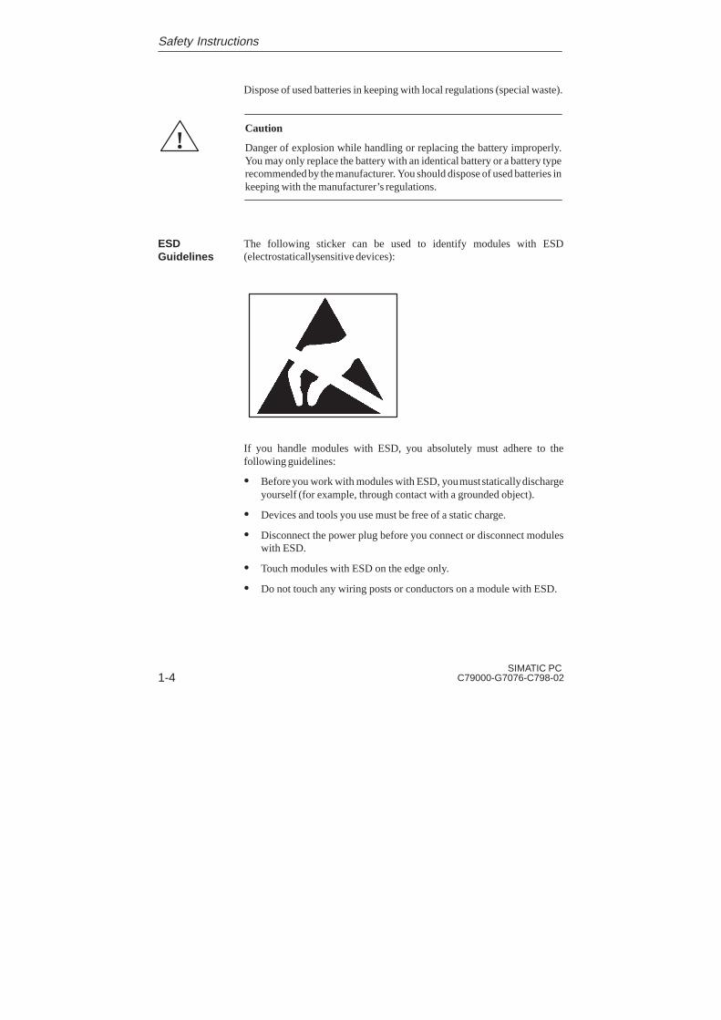
The following sticker can be used to identify modules with ESD(electrostatically sensitive devices):
If you handle modules with ESD, you absolutely must adhere to thefollowing guidelines:
� Before you work with modules with ESD, you must statically dischargeyourself (for example, through contact with a grounded object).
� Devices and tools you use must be free of a static charge.
� Disconnect the power plug before you connect or disconnect moduleswith ESD.
� Touch modules with ESD on the edge only.
� Do not touch any wiring posts or conductors on a module with ESD.
ESDGuidelines
Safety Instructions

English
1-5SIMATIC PCC79000-G7076-C798-02
1.2 Information Regarding the CE Label
The following applies to the SIMATIC product described in this manual:
In accordance with the EU Directive 89/336/EEC “ElectromagneticCompatibility.” In accordance with the CE label for this product, thefollowing areas of application are relevant:
Application Requirements
Area Emitted Interference Immunity
Domestic, businessand commercialareas, as well assmall businesses
EN 50081-1: 1992 EN 50082-1: 1992
Industrial area EN 50081-2: 1993 EN 50082-2: 1995
This product complies with the reqirements of the EU Directive 73/23/EEC“Low-Voltage Directive.” Conformance with this standard has been verifiedaccording to EN60950.
The EU declarations of conformity and the relevant documentation are heldat the disposal of the competent authorities at the address below:
Siemens AktiengesellschaftBereich AutomatisierungstechnikAUT E 8Postfach 1963D-92209 AmbergGermany
Products not bearing the CE label fulfill the requirements and standards asspecified in the section on “Technical Specifications.”
The installation guidelines and safety instructions specified in thedocumentation must be observed during startup and operation.
EMC Directive
Low-VoltageDirective
Declaration ofConformity
Observing theInstallationGuidelines
Safety Instructions

English
1-6SIMATIC PC
C79000-G7076-C798-02
1.3 Approvals for the USA and Canada
Important for the USA and Canada:
The following labels indicate that the relevant approval isavailable for the device bearing the label:
Underwriters Laboratories (UL) to standard UL 1950
Underwriters Laboratories (UL) to Canadian standard C22.2No. 950
UL Recognition Mark
Canadian Standard Association (CSA) to standard C22.2.No. 950
Canadian Standard Association (CSA) to American standardUL 1950
Federal Communications CommissionRadio Frequency Interference Statement
This equipment has been tested and found to comply with the limits for a Class Adigital device, pursuant to Part 15 of the FCC Rules. These limits are designed toprovide reasonable protection against harmful interference when the equipment isoperated in a commercial environment. This equipment generates, uses, and canradiate radio frequency energy and, if not installed and used in accordance with theinstruction manual, may cause harmful interference to radio communications.Operation of this equipment in a residential area is likely to cause harmfulinterference in which case the user will be required to correct the interference at hisown expense.
UL/CSAApproval
C
NRTL
FCC Approvalfor USA andCanada
Safety Instructions

English
1-7SIMATIC PCC79000-G7076-C798-02
Shielded Cables
Shielded cables must be used with this equipment to maintain compliance with FCCregulations.
Modifications
Changes or modifications not expressly approved by the manufacturer could voidthe user’s authority to operate the equipment.
Conditions of Operations
This device complies with Part 15 of the FCC Rules. Operation is subject to thefollowing two conditions: (1) this device may not cause harmful interference, and (2)this device must accept any interference received, including interference that maycause undesired operation.
Canadian Notice
This equipment does not exceed the Class A limits for radiated emissions asdescribed in the Radio Interference Regulations of the Canadian Department ofCommunications.
Avis Canadien
Le présent appareil numérique n’émet pas de bruits radioélectriques dépassant leslimites applicables aux appareils numériques de la Classe A prescrites dans leRéglement sur le brouillage radioélectrique édicté par le Ministère desCommunications du Canada.
Safety Instructions

English
1-8SIMATIC PC
C79000-G7076-C798-02
1.4 Technical Specifications
Order number See title pageDimensions (w x h x d in mm) 448 x 177 x 482Weight approx. 15 kgLine voltage 120 VAC (103 to 132 VAC or
240 VAC (200 to 264 VAC)(no automatic switchover)
Line voltage frequency 50/60 Hz (47 to 63 Hz)Brief voltage interruptionacc. to NAMUR
max. 20 ms at 160 W load
max. power consumption220 Wmax. current delivery+ 12 V can be loadedmax. 10s on 8A
5V
19 A
12V
4.2 A
-5V
0.5 A
-12V
0.5 A
Degree of protection IP41 front with closed protective cover, IP20 on the rear panelSafetyProtection class Protection class I acc. to VDE 0106 T1: 1982 (IEC 536)Safety requirements EN 60950Electromagnetic compatibility (EMC)Emitted interference EN 55022 limited value class BNoise immunity:line-fed interference onsupply lines
+- 2 kV (to IEC 1000-4-4:1995; burst)+- 1 kV (to IEC 1000-4-5:1995; surge symm)+- 2 kV (to IEC 1000-4-5:1995; surge unsymm)
Noise immunity onprocess, measuring, andcontrol lines
+- 1 kV (to IEC 1000-4-4:1995; burst; length < 3m)+- 2 kV (to IEC 1000-4-4:1995; burst; length > 3m)+- 1 kV (to IEC 1000-4-4:1995; surge symm;
length > 3m)+- 2 kV (to IEC 1000-4-4:1995; surge unsymm;
length > 3m)Noise immunity todischarges of staticelectricity
+- 6 kV contact discharge (to IEC 1000-4-2:1995)+- 8 kV air discharge (to IEC 1000-4-2:1995)
Noise immunity tohigh-frequency radiation
10 V/m 80-1000 MHz, 80% AM (to ENV 50140:1993)10 V/m 900 MHz, 50% ED (to ENV 50204:1995)
Safety Instructions

English
1-9SIMATIC PCC79000-G7076-C798-02
Ambient conditionsTemperature
- operation
- storage/transport- gradient
tested to DIN EN 60068-2-2:1994, DIN IEC 68-2-1,DIN IEC 68-2-14
+ 5°C to +45°C40°C for CD-ROM operation- 20°C to +60°Cmax 10°C/h (no condensation)
rel. humidity
- operation- storage/transport
tested to DIN IEC 68-2-3, DIN IEC 68-2-30, DIN IEC 68-2-56
5% to 80% at 25°C (no condensation)5% to 95% at 25°C (no condensation)
Mechanical specificationsVibration
- operation- transport
tested to DIN IEC 68-2-6
10 to 58 Hz: 0.0375 mm, 58 to 500 Hz: 4.9 m/s5 to 9 Hz: 3,5 mm, 9 to 500 Hz: 9.8 m/s
Shock
- operation- storage
tested to DIN IEC 68-2-29
50 m/s2, 30 ms, 100 shocks250 m/s2, 6 ms, 1000 shocks
MotherboardProcessor Pentium 200MMXInternal processor cache 2 x 8 KBMain memory 2 x 8 MByte EDO-SIMM
max. 128 MBSecond level cache 256 kByte synchronExpansion slots RI25/RI45: 6 ISA long format/2 PCI long format
If the device has a SafeCard, this occupies one ISA expansionslot.
max. admissable powerconsumption per ISA slot
max. admissable powerconsumption per PCI slot
5V 2A; 12V 0.3 A; -12 V 0.05 A; -5 V 0.05 A(the sum of 5V 9A must not be exceeded)
5V 2A; 12V 0.5A; -12V 0.1A; -5V 0.1A
DrivesFloppy disk drive 3.5” (1.44 MB)Hard disk drive 3.5” EIDE 3.2 Gbytes (ATA 33), cylinder 6704, sectors 63,
heads 15CD-ROM drive 650 MBytes, type see LogbookCD-ROM port EIDE (secondary)
Safety Instructions

English
1-10SIMATIC PC
C79000-G7076-C798-02
GraphicsGraphics chip SVGA-LCD Controller Cirrus GD7543 on PCI bus with
Windows acceleratorGraphics memory 1 MByte DRAMResolutions/frequencies/colors
CRT: up to 1024x768/75 Hz/256 colors
InterfacesCOM1 Serial port 1 (V24), 25-pin sub-D socketCOM2 Serial port 2 (V24), 9-pin sub-D connetor (standard)LPT1 Parallel port
Connection for printer with parallel portVGA VGA interface, connection for external monitorKeyboard PS/2 keyboard connectionMouse PS/2 mouse connectionMPI/DP interface,optically isolated*
9-pin sub-D socket, screw-type locking
Transmission rate 9.6 Kbps to 1.5 Mbps, assign parameters with softwareOperating mode Optically isolated*: data lines A, B
control lines RTS AS, RTS_PG5V line voltage (max. 90 mA)
Ground connection: MPI/DP connection cable shieldPhysical interface RS485, optically isolatedMemory address area 0CC000H – – 0CC7FFH or
0DC000H – – 0DC7FFH, to be set in BIOS SetupInterrupts IRQ5, 10, 11 or 15 assign parameters with software
(only 1 interrupt possible)Relay interface Connection of a signaling device to a SafeCard monitoring
module. See SafeCard description in the section on“Monitoring Module”.
Function displayLEDs on the device Power
DiskRun (only with SafeCard option)Temp (only with SafeCard option)FloppyCD-ROM
*) Optically isolated within the safety extra-low voltage circuit (SELV)
Safety Instructions

2-1SIMATIC PCC79000-G7076-C798-02
Starting Up Your PC
In this chapter, we tell you:
� What you should note when you set up your PC
� Which interface you use to connect the standard I/Os
� How you connect your PC to the supply voltage
2.1 Unpacking and Checking the Delivery Contents
Proceed as follows to unpack your PC:
1. Remove the packaging material.
2. Do not throw the original packaging material away. Save it in case youneed to transport your PC.
3. Make certain you keep the enclosed documentation. You will need thisdocumentation when you start up your PC for the first time. (SeeChapter 3).
Proceed as follows:
1. Check the delivery against the packing list to make certain you havereceived everything.
2. Check the delivery to see if there are any transport damages apparent.
3. Inform your supplier immediately if there are any transport damages ordifferences between the packing list and the actual delivery.
If necessary, refer to the logbook on the inside of your PC to obtain the exactcomputer configuration.
Your SIMATIC PC can be used as a 19” built-in or for desktop operation.Section 2.2 provides you with more information.
Chapter Overview
UnpackingthePC RI25/45
Checking
Setting Up
2

English
2-2SIMATIC PC
C79000-G7076-C798-02
2.2 Installing Your PC in a 19” Cabinet or Rack(19” Operation)
The installation height for your SIMATIC PC is only four ET (heightmodules = 177 mm, Figure 2-1). Therefore, special installation assembliesare not required for installing this computer in a 19” cabinet or rack. Youmust use four screws to fix the computer into position on the cabinet’s braces.However, you should under no circumstances mount the computer just onthese screws (without rack slide rails). Use the respective manufacturer’scabinet or rack slide rails or L-sections. Contact your cabinet supplierdirectly regarding cabinet or rack installation.
101
483
SIEMENS
465
177
38 10
448
438
482
(18,31)
(19,02)
(17,64)
(0,3
9)(1
8,98
)(1
7,24
)
(1,5
)(3
,98)
(4,6
1)
All
dim
ensi
ons
in m
mA
ll di
men
sion
s (
) in
inch
es
Figure 2-1 SIMATIC PC Installation Dimensions
Layout
Starting Up Your PC

English
2-3SIMATIC PCC79000-G7076-C798-02
!Warning
Avoid extreme ambient conditions as far as possible. Protect your SIMATICPC from dust, moisture, and heat. (Refer to the “System Unit” section in theTechnical Description.)
Mount the device as safely as possible to prevent any danger (for example,by falling over).
The clearance around the system unit must be at least 200 mm at the frontand rear, so that the system unit is sufficiently ventilated.
Make certain that the ventilation slots for the system unit and the monitorare not covered.
Make certain that the sliding door in front of the drives is closed duringoperation. If the sliding door is not closed, insufficient air is drawn throughthe ventilation slots to cool the interior of the system unit.
Starting Up Your PC

English
2-4SIMATIC PC
C79000-G7076-C798-02
2.3 Connecting I/O Devices (such as a Monitor, Mouse, orKeyboard)
All of the connections and interfaces for connecting I/O devices are mountedon the back of the system housing.
Network connection unit
Earthing studs
PS/2 keyboard
PS/2 mouse
LPT
MPI
COM1
COM2
VGA
Relay (only in connectionwith a SafeCard)
Strain relief devices
Figure 2-2 Rear Panel of the System Housing
Note
Make sure you follow the safety instructions in Chapter 1 when connectingI/O devices!
Rear Panel ofthe Device
Starting Up Your PC

English
2-5SIMATIC PCC79000-G7076-C798-02
Table 2-1 Connections on the Back of the PC
Connections Function
VGA VGA interfaceConnection for external monitor
COM1 Serial interface 1 (RS 232)25-pin sub-D socket
COM2 Serial interface 2 (RS 232)9-pin sub-D connector (standard)
Mouse PS/2 mouse connection
Keyboard PS/2 keyboard connection
LPT1/Printer Parallel portConnection for printer with parallelinterface
MPI/DPMultipoint Interface(RS 485)*
Multipoint InterfaceConnection for a SIMATIC S7programmable logic controller system
Inlet connector input Power connection (115/230 VAC)
Inlet connector output Power connection for an external monitor(115/230 VAC)
Relay output (only in connection with aSafeCard)
Connection for a signal device on theSafeCard monitoring module. Refer to thedescription of the SafeCard in the“Monitoring Module” section in theTechnical Description.Technical specifications:DC switching voltage : max. 60VDC switching current : max. 1ADC switching cap. : max. 30WPermanent DC curr. : max. 1A
* Optically isolated within the safety extra-low voltage circuit (SELV)
If expansion boards are connected in the PC, there are additional interfaces.Please refer to the description of the relevant module for the significance ofthese additional interfaces.
Starting Up Your PC
English
2-6SIMATIC PC
C79000-G7076-C798-02
Note
When connecting I/O devices, watch out for shielded cables and metalconnectors, or you will terminate the operating license! Use a screwdriverto place the interface cable connectors on the PC housing. This improves theelectrical shielding.
After the PS/2 connector is connected, both cables must be secured with theprovided strain relief device. This keeps the PS/2 connector from comingloose when the mouse or keyboard is moved.
Connectingthe Keyboardand Mouse
Starting Up Your PC
English
2-7SIMATIC PCC79000-G7076-C798-02
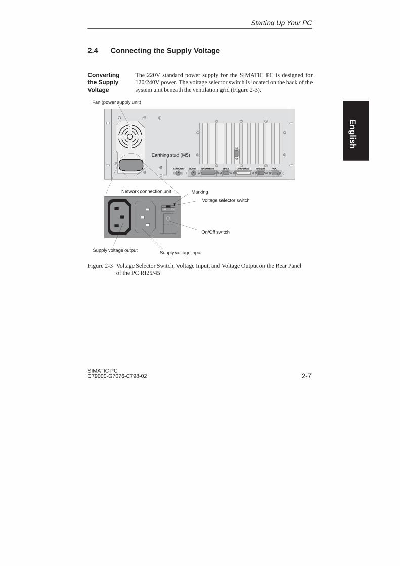
2.4 Connecting the Supply Voltage
The 220V standard power supply for the SIMATIC PC is designed for120/240V power. The voltage selector switch is located on the back of thesystem unit beneath the ventilation grid (Figure 2-3).
Network connection unit
On/Off switch
�
Voltage selector switch
Marking
Fan (power supply unit)
Supply voltage output Supply voltage input
Earthing stud (M5)
Figure 2-3 Voltage Selector Switch, Voltage Input, and Voltage Output on the Rear Panel of the PC RI25/45
Convertingthe SupplyVoltage
Starting Up Your PC

English
2-8SIMATIC PC
C79000-G7076-C798-02
If the voltage indicated on the voltage selector switch does not correspondto your local supply voltage, you must change the position of the voltageselector switch so that the marker points to the required supply voltage.
!Warning
Damage may be caused to device!
The RI may be damaged due to a wrong supply voltage setting. The samevoltage is applied to the supply voltage output and the supply voltage input.
Please observe the specifications made by the monitor manufacturer whenoperating the monitor.
The following table lists the permissible input currents for the monitor:
Input voltage 120 V / 240 V ± 10%
Input current 4 A / 3 A
Output voltage Equal to input voltage
Max. output current 1 A / 0.5 A
1. Make certain that the supply voltage set on the voltage selector switch matches your localsupply voltage.
2. Connect the power supply cable for the monitor to the PC RI depending on the connectortype, or connect the power supply cable to the grounding outlet. Please observe the maximumcurrent limit when connecting to the PC RI (see back of device).
3. Connect the power supply cable supplied to the PC RI.
4. Connect the device to a grounding outlet.
5. An earthing stud (M5) can be used to guarantee equipotential bonding between the PC andits surroundings.
Selecting theSupplyVoltage
Starting Up Your PC

3-1SIMATIC PCC79000-G7076-C798-02
Setting Up and Operating Your PC
In this chapter, we:
� Introduce you to the operator elements of the SIMATIC PC.
� Describe the initial installation.
� Describe how to use the electronic manual.
Chapter Overview
3

English
3-2SIMATIC PC
C79000-G7076-C798-02
3.1 Operator Elements of the System Unit
Before you switch on your SIMATIC PC , you should become familiar withits operator elements. Figure 3-1 illustrates the operator elements on the frontside of your PC.
Operator panel
Floppy disk drive Status display
LEDs
Reset key
Lock
Standby/operating switch
Figure 3-1 Operator Elements on the Front Side of the SIMATIC PC
The following functions appear on the operator panel:
� LEDs for displaying:
– Power
– Hard disk
– Run (watchdog) (only in connection with a SafeCard)
– Temperature (only in connection with a SafeCard)
� Speaker
� Status display (only in connection with a SafeCard)
� Reset key
� Sliding door lock (access protection)
Front Side
OperatorPanel
Setting Up and Operating Your PC
English
3-3SIMATIC PCC79000-G7076-C798-02
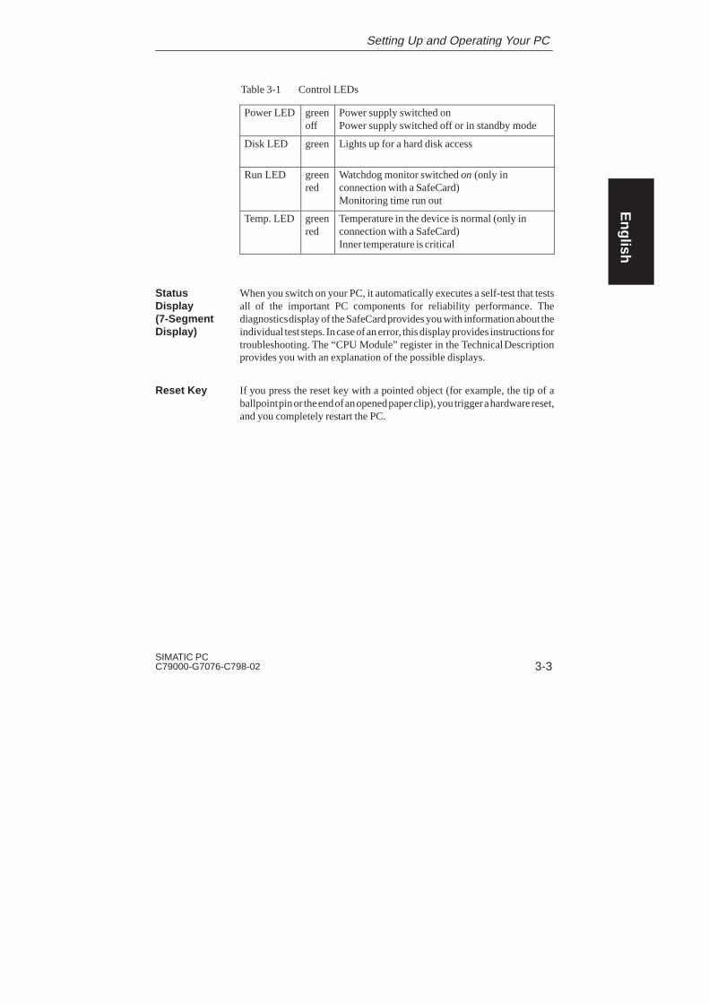
Table 3-1 Control LEDs
Power LED greenoff
Power supply switched onPower supply switched off or in standby mode
Disk LED green Lights up for a hard disk access
Run LED greenred
Watchdog monitor switched on (only inconnection with a SafeCard)Monitoring time run out
Temp. LED greenred
Temperature in the device is normal (only inconnection with a SafeCard)Inner temperature is critical
When you switch on your PC, it automatically executes a self-test that testsall of the important PC components for reliability performance. Thediagnostics display of the SafeCard provides you with information about theindividual test steps. In case of an error, this display provides instructions fortroubleshooting. The “CPU Module” register in the Technical Descriptionprovides you with an explanation of the possible displays.
If you press the reset key with a pointed object (for example, the tip of aballpoint pin or the end of an opened paper clip), you trigger a hardware reset,and you completely restart the PC.
StatusDisplay(7-SegmentDisplay)
Reset Key
Setting Up and Operating Your PC

English
3-4SIMATIC PC
C79000-G7076-C798-02
3.2 Starting Up Your PC for the First Time
Your PC is ready for system operation after you connect the I/O devices andthe system unit. You can now switch to standby mode using the switch onthe power supply unit. The power switch is located on the back of the powersupply unit. When you press the standby/operating switch, the PC switchesfrom standby mode to active operation. The green light of the power supplyis lit.
The standby/operation switch is located behind the drive cover on the frontof the device.
Standby/operating switch
Figure 3-2 Switching on the System Unit
To change from active operation to standby mode you must press thestandby/operation switch again.
When you switch off the system unit, you must disengage the ON/OFFswitch.
Switching On
Standby
Switching Off
Setting Up and Operating Your PC
English
3-5SIMATIC PCC79000-G7076-C798-02
Note
When your PC is switched on, the POWER LED is green. The ON/OFFswitch on the power supply unit does not separate the system unit from thepower supply. You must unplug the power plug to separate the system unitfrom the power supply completely.
Setting Up and Operating Your PC

English
3-6SIMATIC PC
C79000-G7076-C798-02
3.3 Setting Up Your PC
The operating system and the system software for your PC werefactory-installed on the hard drive.
You must differentiate the following two instances when you switch on yourPC:
� Initial startup
� Complete restart
Your PC software is set up during the initial startup. Proceed as follows:
1. Switch on your PC.
2. Set the monitor’s brightness control switch to bright. (Refer to theoperating instructions for the monitor.) Switch on the monitor.
The PC conducts a self-test. The following message appears brieflyduring the self-test:
Press <F2> to enter SETUP
3. Wait until the message disappears and then follow the instructions on thescreen.
Your operating system loads after the self-test is finished. The loadingprocedure depends on the operating system and therefore varies,depending on your PC variation (Sections 3.4 and 3.5).
Once your PC is set up, the operating system interface will be automaticallydisplayed after the startup procedure every time you switch on or reset thePC.
Overview
Initial Startup
CompleteRestart
Setting Up and Operating Your PC
English
3-7SIMATIC PCC79000-G7076-C798-02
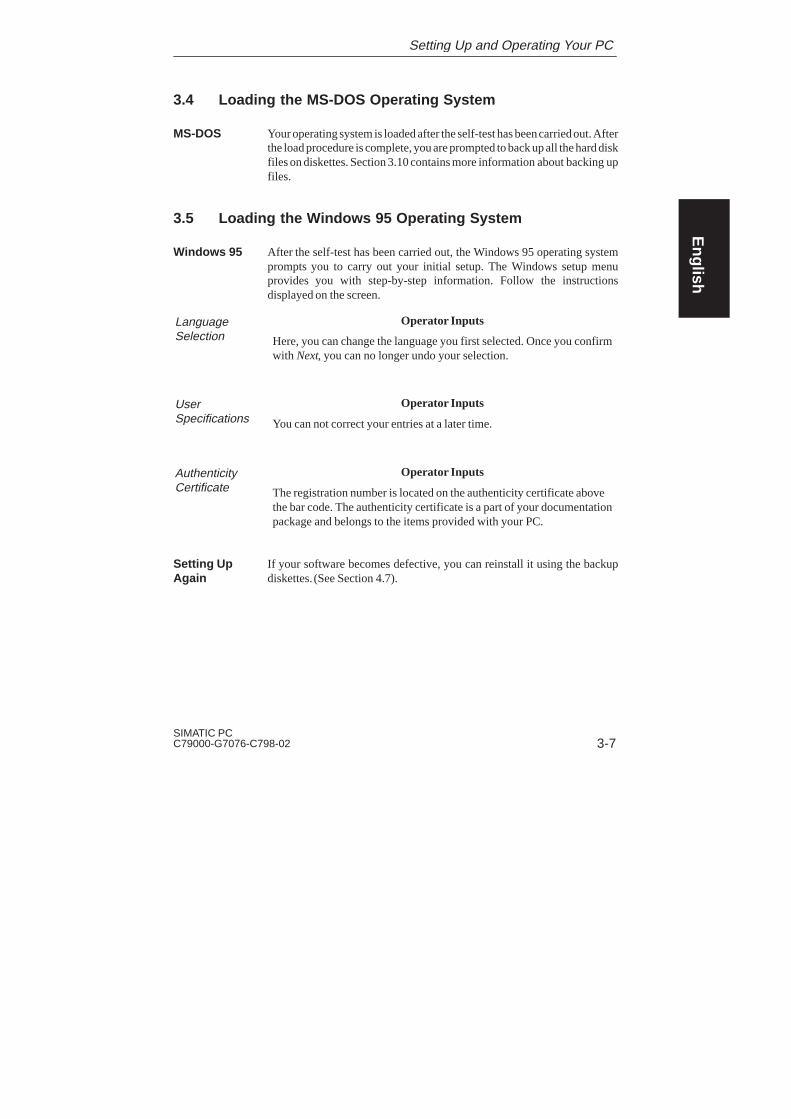
3.4 Loading the MS-DOS Operating System
Your operating system is loaded after the self-test has been carried out. Afterthe load procedure is complete, you are prompted to back up all the hard diskfiles on diskettes. Section 3.10 contains more information about backing upfiles.
3.5 Loading the Windows 95 Operating System
After the self-test has been carried out, the Windows 95 operating systemprompts you to carry out your initial setup. The Windows setup menuprovides you with step-by-step information. Follow the instructionsdisplayed on the screen.
Operator Inputs
Here, you can change the language you first selected. Once you confirmwith Next, you can no longer undo your selection.
Operator Inputs
You can not correct your entries at a later time.
Operator Inputs
The registration number is located on the authenticity certificate abovethe bar code. The authenticity certificate is a part of your documentationpackage and belongs to the items provided with your PC.
If your software becomes defective, you can reinstall it using the backupdiskettes. (See Section 4.7).
MS-DOS
Windows 95
LanguageSelection
User Specifications
AuthenticityCertificate
Setting UpAgain
Setting Up and Operating Your PC
English
3-8SIMATIC PC
C79000-G7076-C798-02
3.6 Electronic Manual
Your PC is equipped with an electronic manual. This manual consists of twoparts:
– The User’s Guide (the document you are reading now) in fourlanguages (German, English, French, and Italian) and
– The Technical Description in two languages (German and English)
The User’s Guide is located in the DOCU directory:
c:\DOCU\U_MAND.PDF (German manual)c:\DOCU\U_MANE.PDF (English manual)c:\DOCU\U_MANF.PDF (French manual)c:\DOCU\U_MANI.PDF (Italian manual)
The Technical Description is located in the DOCU directory:
c:\DOCU\T_DESD.PDF (German Technical Description)c:\DOCU\T_DESE.PDF (English Technical Description)
You need the ADOBE Acrobat Reader to read and print out the user’s guideand the Technical Description. The ADOBE Acrobat Reader is a softwarepackage located in the following directory:
c:\acrodos or c:\acroread
For technical licensing reasons, we do not pre-install the software. This mustbe installed by the user.
Note
We recommend that you print out a copy of the Technical Descriptionduring startup and store it together with the Manual.
Overview
User’s Guide
Technical Description
ADOBEAcrobatReader
Setting Up and Operating Your PC

English
3-9SIMATIC PCC79000-G7076-C798-02
3.7 Installing Adobe Acrobat
Before you install the Acrobat Reader, we recommend that you connect amouse and install the mouse driver. It is possible to operate the AcrobatReader with the keyboard, but it is considerably easier to use the mouse.
From steps 2 through 6, the installation procedure is identical for both theDOS and Windows 95 operating systems. Proceed as follows:
1. Start:
� Install.exe in the c:\acrodos for MS-DOS
� acroread.exe in the c:\acroread for Windows 95.
The following message appears:Adobe Acrobat Reader for DOS Installation,version x.y orAdobe Acrobat Reader for WINDOWS Installation,version x.y
2. Use any key to confirm your entry.
The following license agreement appears:Adobe Systems Incorporated License Agreement
3. Confirm your answer with Accept.
4. You are prompted to enter your name.Use the ENTER key to confirm your answer.
5. Your are prompted to enter your organization.Use the ENTER key to confirm your answer.
6. You are prompted to specify the directory where you want theinstallation to take place. Use the suggested directory.Use the ENTER key to confirm your answer.
In Windows 95, the installation now runs automatically. The installationends when the Acrobat Reader icon appears in a window.
AcrobatReaderInstallation
Setting Up and Operating Your PC
English
3-10SIMATIC PC
C79000-G7076-C798-02
Additional steps are required for the SIMATIC PC RI with MS-DOS:
1. You are prompted to specify a directory for printing fonts. Use thesuggested directory and confirm with the ENTER key.
2. You are prompted to choose if you wish to install the Reader Tour, atutorial which requires approx. 0.5 MB on the hard disk.Use the ENTER key to confirm your answer.
3. You are prompted to specify your working directory (temporarydirectory). Use the suggested directory and confirm with the ENTERkey.
4. You are prompted to specify a directory for the swap-out file.Use the suggested directory and confirm with the ENTER key.
5. You are prompted to decide if you want modifications in theCONFIG.SYS and AUTOEXEC.BAT files to be made automatically bythe installation program, or if you wish to make them yourself. Werecommend you select the suggested option:Go ahead and modifyand to confirm your selection with the ENTER key.
6. A message is now displayed if you have not connected a mouse andinstalled a mouse driver. You can do this after the installation of AdobeAcrobat is finished. Confirm with ENTER.
7. After installation has been finished, you are prompted to reboot your PC.Confirm with ENTER and reboot your PC (press CTRL-ALT-DEL orthe reset key).
8. In order to edit larger documents, you must first carry out the followingsteps:
� cd C:\ACRODOS ; Select the root directory C:\
� ACROBAT ; Start the ACROBAT reader
� <ALT F> ; Select the PREFERENCES submenu
� LARGE ; Set the setting “virtual memory size” to LARGE
� OK ; Exit the menu
� <ALT F> ; Exit the ACROBAT reader
� EXIT The settings are complete and will be saved
AdditionalSteps
Setting Up and Operating Your PC

English
3-11SIMATIC PCC79000-G7076-C798-02
3.8 Using Adobe Acrobat
Proceed as follows to use the Acrobat Reader:
1. To start the Acrobat Reader, type in acrobat in MS-DOS. InWindows 95, click on the Acrobat Reader icon. You can start theAcrobat Reader from any directory, if you followed therecommendation during installation.
An interface that looks like the MS-DOS shell appears. Use the TAB keyor the mouse to switch between windows. Use the cursor keys on thekeyboard (or use the mouse) to move the cursor between windows.(Important: your selection is not chosen until the line is displayedinversely, that is, white lettering on a dark background.)
2. Open the file you want to read
U_MANE.PDF User’s GuideT_DESE.PDF Technical Description
These files are located in the c:\docu directory.
3. Use the FILE menu to print out the opened file. First choose PRINTERSETUP from the FILE menu. Then make your selection according to theprinter you have connected. Then you choose PRINT from the FILEmenu to print out your file.
3.9 SafeCard
Please refer to the Technical Description for notes on the SafeCard module.
When installing the SafeCard driver for various operating systems, refer tothe ReadMe.TXT file in directory C:\SAFECARD.
Using theAcrobatReader
Setting Up and Operating Your PC

English
3-12SIMATIC PC
C79000-G7076-C798-02
3.10 Backing Up Hard Disk Data on Diskettes
When it is delivered, the hard drive of your industrial PC contains importantdata and programs (for example, the operating system). It is essential that youmake backup copies of these files on diskette. These data may be lost if thereis an operating error or if there is a hard drive defect.
Your industrial PC is delivered with a batch routine that considerablysimplifies data backup during the initial installation. Backing up the harddrive data is menu-driven:
� Follow the instructions for the backup program. To back up the harddrive data, you need a number of formatted, blank diskettes (at leastsixteen).
During the initial installation of the operating system, you are prompted toback up (refer to Section 3.5). You need 32 formatted, blank diskettes(1.44 Mbytes) for the backup.
Refer to Section 4.7 to set up your PC again.
3.11 Safety Functions
Using passwords during setup, you can keep unauthorized persons frommaking entries in the setup. Refer to the CPU module section in the TechnicalDescription for more information on setup passwords (see Section 3.6).
Overview
Backing Up inMS-DOS
Backing Up inWindows 95
Setting Up and Operating Your PC
English
3-13SIMATIC PCC79000-G7076-C798-02
3.12 CD-ROM Drive
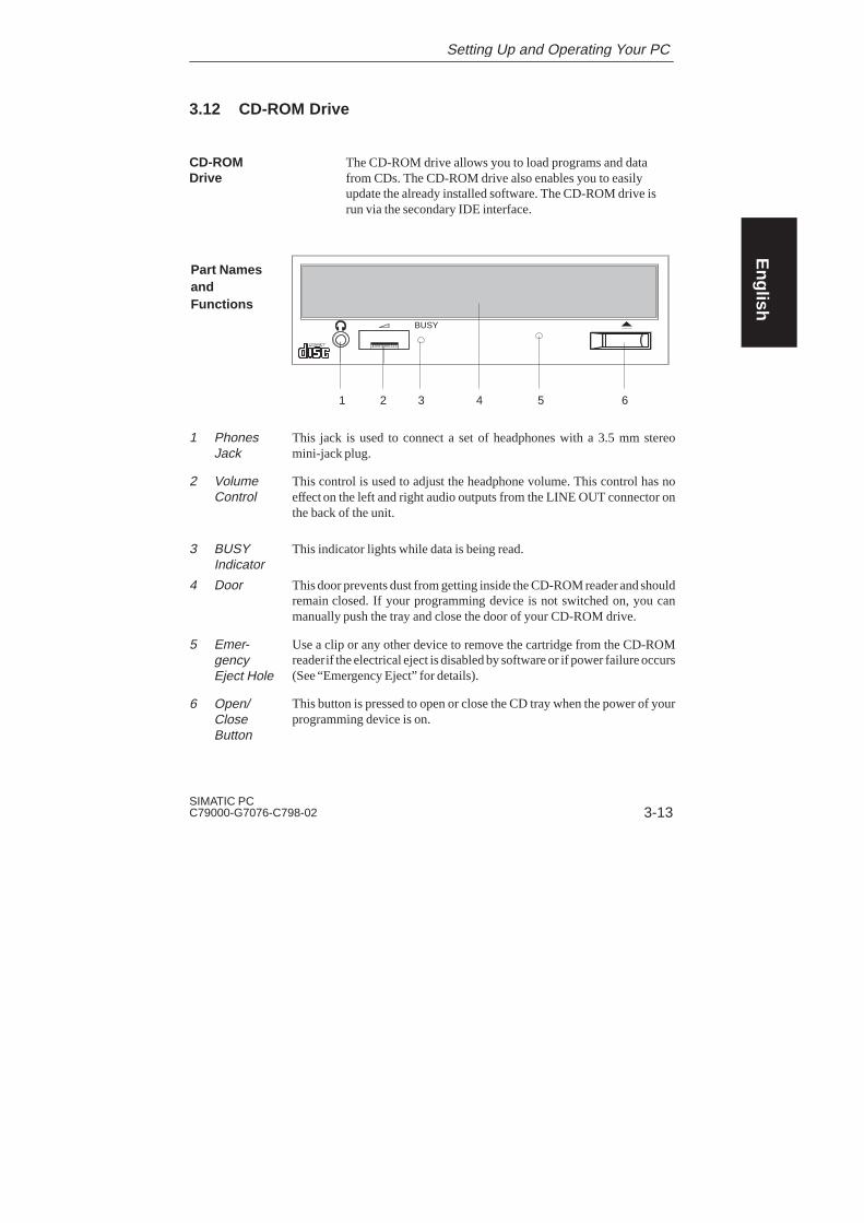
The CD-ROM drive allows you to load programs and datafrom CDs. The CD-ROM drive also enables you to easilyupdate the already installed software. The CD-ROM drive isrun via the secondary IDE interface.
BUSY
1 2 3 4 5 6
This jack is used to connect a set of headphones with a 3.5 mm stereomini-jack plug.
This control is used to adjust the headphone volume. This control has noeffect on the left and right audio outputs from the LINE OUT connector onthe back of the unit.
This indicator lights while data is being read.
This door prevents dust from getting inside the CD-ROM reader and shouldremain closed. If your programming device is not switched on, you canmanually push the tray and close the door of your CD-ROM drive.
Use a clip or any other device to remove the cartridge from the CD-ROMreader if the electrical eject is disabled by software or if power failure occurs(See “Emergency Eject” for details).
This button is pressed to open or close the CD tray when the power of yourprogramming device is on.
CD-ROMDrive
Part NamesandFunctions
1 PhonesJack
2 VolumeControl
3 BUSYIndicator
4 Door
5 Emer-gencyEject Hole
6 Open/CloseButton
Setting Up and Operating Your PC
English
3-14SIMATIC PC
C79000-G7076-C798-02
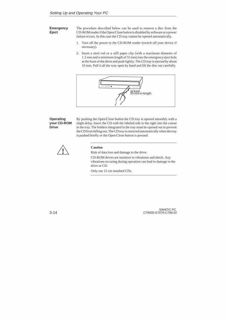
The procedure described below can be used to remove a disc from theCD-ROM reader if the Open/Close button is disabled by software or a powerfailure occurs. In this case the CD tray cannot be opened automatically.
1. Turn off the power to the CD-ROM reader (switch off your device ifnecessary).
2. Insert a steel rod or a stiff paper clip (with a maximum diameter of1.3 mm and a minimum length of 55 mm) into the emergency eject holeat the front of the drive and push lightly. The CD tray is ejected by about10 mm. Pull it all the way open by hand and lift the disc out carefully.
at least55 mm in length
By pushing the Open/Close button the CD tray is opened smoothly with aslight delay. Insert the CD with the labeled side to the right into the cutoutin the tray. The holders integrated in the tray must be opened out to preventthe CD from falling out. The CD tray is retracted automatically when the trayis pushed briefly or the Open/Close button is pressed.
!CautionRisk of data loss and damage to the drive.
CD-ROM drives are sensitive to vibrations and shock. Anyvibrations occuring during operation can lead to damage to thedrive or CD.
Only use 12 cm standard CDs.
EmergencyEject
Operatingyour CD-ROMDrive
Setting Up and Operating Your PC

4-1SIMATIC PCC79000-G7076-C798-02
Error Diagnostics
This chapter provides you with tips on how to localize and troubleshootfrequently occurring problems.
� Refer to your operating system documentation for operating systemerror messages.
� Refer to the “CPU Module” section in the Technical Description forexplanations of error messages caused by the CPU. Refer to Sections 4.8and 4.9 of this manual for error messages that occur during the self-test(display LEDs and screen messages).
Note
If you want to disconnect or connect cables, note of the safety instructionsin Chapters 1 and 2.
Chapter Overview
4
English
4-2SIMATIC PC
C79000-G7076-C798-02
4.1 The PC Does not React to the ON/OFF Switch
The PC does not show any reaction at all when it is switched on. The powerLED does not light up.
The power supply is faulty.
Proceed as follows:
� Is the standby/operating switch on?
� Switch the PC off at the power supply unit.
� Check whether the power supply cable is connected.
� Check whether the power supply connector is connected correctly.
� Switch the PC on again at the power supply unit and press the standby/operating switch.
Note
If no LED lights up on the system unit after you have carried out thesechecks and measures, notify your technical support team (Chapter 5).
Error Display
Cause
Remedy
Error Diagnostics

English
4-3SIMATIC PCC79000-G7076-C798-02
4.2 Problems When Using Modules from OtherManufacturers
The PC crashes during power-up.
The following causes are possible:
– Double assignment of input/output addresses
– Double assignment of hardware interrupts and/or DMA channels
– Signal frequencies or signal levels are not met
– Deviating connector assignment
Use the logbook (located inside the PC) to check your computerconfiguration.
� If the computer configuration is the same as when your PC wasdelivered, please contact your technical support team (Chapter 5).
� If the computer configuration has changed, re-establish theconfiguration you had when your PC was delivered. Remove anymodules from other manufacturers. Perform a complete restart on yourPC.
– If the PC still crashes, you must contact your technical support team.
– If the error no longer occurs, the module you used from anothermanufacturer was the cause of the fault. Replace this module with aSiemens module, or contact the module supplier.
Error Display
Cause
Remedy
Error Diagnostics

English
4-4SIMATIC PC
C79000-G7076-C798-02
4.3 The Monitor Remains Dark
The following causes are possible:
The monitor has been switched off.
� Switch on the monitor.
The monitor is in “powersave” mode.
� Press any key on the keyboard.
The brightness button has been set to dark.
� Set the screen’s brightness button to obtain more light. Refer to theoperator’s guide for the monitor for more detailed information.
The power supply cable or the screen cable is not connected.
� Switch off the monitor and the system unit.
� Check whether the power supply cable has been connected correctly tothe monitor and to the system unit or to the grounding outlet.
� Check whether the monitor cable has been connected correctly to thesystem unit and to the screen (if a connector is present).
� Switch on the monitor and the system unit.
Note
If the monitor screen still remains dark after these checks and measures havebeen carried out, please contact your technical support team (Chapter 5).
Cause andRemedy
Error Diagnostics

English
4-5SIMATIC PCC79000-G7076-C798-02
4.4 The Screen Display Does not Appear or Drifts
Either the incorrect line frequency and/or the incorrect resolution is set forthe screen or for the user program.
� Stop the user program. If the error still occurs after you have ended theprogram, switch off the monitor. After at least three seconds, switch onthe monitor again.
� Adjust the relevant entries for the monitor in the CONFIG.SYS file (onthe hard drive).
� Correct the settings for the monitor and graphics in your user program.
� Select the correct screen driver for your user program.
Cause andRemedy
Error Diagnostics
English
4-6SIMATIC PC
C79000-G7076-C798-02
4.5 No Mouse Pointer Appears on the Screen
The mouse pointer may not appear for the following reasons:
The mouse driver is not loaded.
� Check whether the mouse driver is correctly installed. Check whetherthe mouse pointer is present when you start your user program. Refer tothe manuals for the mouse and user program to obtain detailedinformation about the mouse driver.
The mouse is not connected.
� Switch off your PC.
� Check whether the mouse cable is connected to the system unit correctly.If you use an adapter or an extension cord for the mouse cable, also checktheir plug-in connections.
� Switch on your PC.
Note
If the mouse pointer still does not appear on the screen after you haveperformed these checks and measures, please contact your technical supportteam (Chapter 5).
Cause andRemedy
Error Diagnostics

English
4-7SIMATIC PCC79000-G7076-C798-02
4.6 The Clock Time and/or the Date in Your PC Is Incorrect
Set the clock time and the date in the setup menu.
Press <F2> to call setup when booting the computer.
Note
The battery is dead if the clock time and the date are still incorrect after youswitch off your PC and switch it back on again. In this case, please contactyour technical support team (Chapter 5).
Remedy
Error Diagnostics

English
4-8SIMATIC PC
C79000-G7076-C798-02
4.7 Rebooting Your Hard Drive (Data Deleted)
If you have created a system diskette and a backup copy of the hard drive,you can reboot your hard drive again. The directories and files present onyour hard drive when you created your backup diskette are recreated.
1. Start your PC with the inserted system diskette.
2. Partition your hard drive with the FDISK MS-DOS command.(You must have knowledge of the system to carry this out.)
3. Format the hard drive with the FORMAT MS-DOS command and the /soption (for example, FORMAT c: / s). The option /s causes thesystem files you need to start the operating system to be copied to thehard drive.
Re-create your files on the hard disk. Use the XCOPY MS-DOS commandand your backup diskettes, which have been created as specified inSection 3.11. Insert the first backup diskette.
1. Start copying the data to the hard disk using the following command:
A: <CR>XCOPY *.* C:\ /s<CR>
2. After the first diskette has been copied, insert the next diskette. Repeatthis procedure until all diskettes have been copied. Now you havere-established the hard disk’s original delivery status.
3. If your hard disk still works incorrectly after you have carried out thesesteps, it needs to be exchanged.
Cause andRemedy
UnderMS-DOS 6.22
Error Diagnostics
English
4-9SIMATIC PCC79000-G7076-C798-02
Follow the instructions given in the chapter Installing Windows 95 of theUser’s Guide Introduction to Microsoft Windows 95. Here is someadditional information:
Starting SETUP for Windows 95
1. Start SETUP.EXE.
2. Confirm with Enter when the first message appears.
3. Quit SCANDISK after it has ckecked your drives by confirming withExit .
4. The Welcome screen form of the Setup program appears. Confirm withContinue. Setup performs routine checks on your PC and prepares theSetup utility.
5. You are requested to insert further diskettes and to confirm with OK.
License Agreement for Windows 95
6. Carefully read the MICROSOFT WINDOWS 95 END USERLICENSE AGREEMENT and agree to its conditions with YES.
Windows 95 Setup Utility
7. First the system information request occurs, which you start withContinue. Then you have to select the directory. Select C:\Windowsand confirm with Continue.
8. The Standard Setup mode is suggested. Confirm with Continue.
Hardware Recognition
9. Make sure that all devices and modules have been correctly connectedor installed and activate the check boxes of the additionally connectedcomponents. Confirm with Continue. This procedure may take a fewminutes.
UnderWindows 95
Error Diagnostics

English
4-10SIMATIC PC
C79000-G7076-C798-02
Unlimited Communication
10. Activate the check boxes for the communication programs, you want toinstall. Confirm your selection with Continue.
Windows Components
11. Select as recommended Install standard components. Acknowledgewith Continue.
Create Start Diskette
12. Select No for the option Create start diskette and confirm withContinue.
Start Copying the Windows 95 Files
13. Confirm Copy Windows 95 files with Continue. The Windows files arethen copied onto the hard disk.
Complete System Restart
14. After the files have been copied, the complete system restart is prepared.Confirm System restart and exit installation with Continue. After thisacknowledgement a complete system restart is performed.
The first startup of Windows 95 is prepared and the configuration files areupdated. The Control Panel is generated, the programs are entered in the startmenu, the Windows help files are prepared and the MS-DOS programs areconfigured.
Time Zone
15. You can now select the time zone of your country/state using the mouse.Confirm your selection with Close.
The Windows 95 installation is now complete.
Error Diagnostics
English
4-11SIMATIC PCC79000-G7076-C798-02
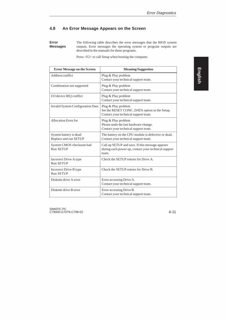
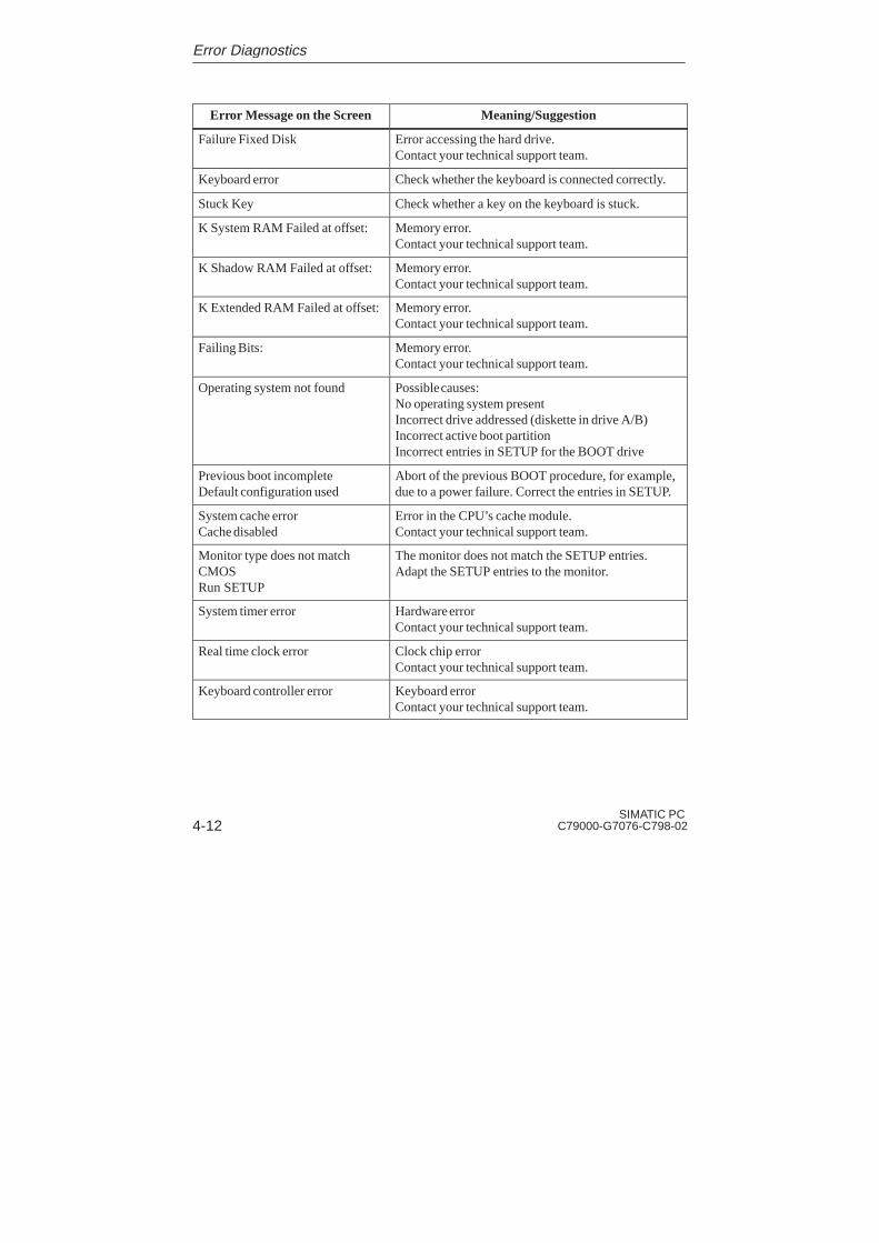
4.8 An Error Message Appears on the Screen
The following table describes the error messages that the BIOS systemoutputs. Error messages the operating system or program outputs aredescribed in the manuals for these programs.
Press <F2> to call Setup when booting the computer.
Error Message on the Screen Meaning/Suggestion
Address conflict Plug & Play problemContact your technical support team.
Combination not supported Plug & Play problemContact your technical support team.
I/O device IRQ conflict Plug & Play problemContact your technical support team.
Invalid System Configuration DataPlug & Play problemSet the RESET CONF...DATA option in the Setup.Contact your technical support team.
Allocation Error for Plug & Play problemPlease undo the last hardware change.Contact your technical support team.
System battery is deadReplace and run SETUP
The battery on the CPU module is defective or dead.Contact your technical support team.
System CMOS checksum badRun SETUP
Call up SETUP and save. If this message appearsduring each power up, contact your technical supportteam.
Incorrect Drive A typeRun SETUP
Check the SETUP entries for Drive A.
Incorrect Drive B typeRun SETUP
Check the SETUP entries for Drive B.
Diskette drive A error Error accessing Drive A.Contact your technical support team.
Diskette drive B error Error accessing Drive B.Contact your technical support team.
ErrorMessages
Error Diagnostics
English
4-12SIMATIC PC
C79000-G7076-C798-02
Error Message on the Screen Meaning/Suggestion
Failure Fixed Disk Error accessing the hard drive.Contact your technical support team.
Keyboard error Check whether the keyboard is connected correctly.
Stuck Key Check whether a key on the keyboard is stuck.
K System RAM Failed at offset: Memory error.Contact your technical support team.
K Shadow RAM Failed at offset: Memory error.Contact your technical support team.
K Extended RAM Failed at offset: Memory error.Contact your technical support team.
Failing Bits: Memory error.Contact your technical support team.
Operating system not found Possible causes:No operating system presentIncorrect drive addressed (diskette in drive A/B)Incorrect active boot partitionIncorrect entries in SETUP for the BOOT drive
Previous boot incompleteDefault configuration used
Abort of the previous BOOT procedure, for example,due to a power failure. Correct the entries in SETUP.
System cache errorCache disabled
Error in the CPU’s cache module.Contact your technical support team.
Monitor type does not matchCMOSRun SETUP
The monitor does not match the SETUP entries.Adapt the SETUP entries to the monitor.
System timer error Hardware errorContact your technical support team.
Real time clock error Clock chip errorContact your technical support team.
Keyboard controller error Keyboard errorContact your technical support team.
Error Diagnostics

English
4-13SIMATIC PCC79000-G7076-C798-02
4.9 Error Messages During the Self-Test (POST Codes)
After the PC R125 P is switched on, a self-test (POST = Power On Self Test)is performed. If errors are detected during the POST, the tone sequence (beepcode) which corresponds to the POST code is issued. The beep code consistsof 2 x 2 sequences.
Conversion table showing the beep codes in hex format.
Beep Tones Hex CodeB B 0
B BB 1
B BBB 2
B BBBB 3
BB B 4
BB BB 5
BB BBB 6
BB BBBB 7
BBB B 8
BBB BB 9
BBB BBB A
BBB BBBB B
BBBB B C
BBBB BB D
BBBB BBB E
BBBB BBBB F
Example:
B BBB BBBB BBB Tone sequence
2 E Hex code
Error during: RAM basic test Meaning
Error Diagnostics

English
4-14SIMATIC PC
C79000-G7076-C798-02
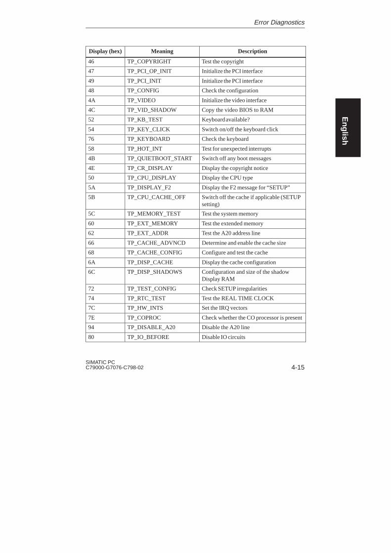
The POST Codes in Order of Occurrence
Display (hex) Meaning Description
02 TP_VERIFY_REAL Test whether the CPU is in real mode
04 TP_GET_CPU_TYPE Determine the CPU type
06 TP_HW_INIT Initialize the main hardware (DMA andIRQ)
18 TP_TIMER_INIT Initialize the timer
08 TP_CS_INIT Initialize the chip set
0C TP_CACHE_INIT Initialize the cache
16 TP_CHECKSUM EPROM checksum test
28 TP_SIZE_RAM Determine the RAM size
3A TP_CACHE_AUTO Determine the cache size
2A TP_ZERO_BASE Set 512k base RAM to 0
2C TP_ADDR_TEST Test the base RAM address cables
2E TP_BASERAML Check the 1.64k base RAM
38 TP_SYS_SHADOW BIOS shadow
20 TP_REFRESH Refresh circuit test
09 TP_SET_IN_POST Start power ON self-test
0A TP_CPU_INIT Initialize the CPU
0B TP_CPU_CACHE_ON Switch on the cache
0F TP_FDISK_INIT Initialize the hard disk
14 TP_8742_INIT Initialize the 8742 circuit
1A TP_DMA_INIT Initialize the DMA circuits
1C TP_RESET_PIC Reset the interrupt controller
22 TP_8742_TEST Test circuit 8742
32 TP_COMPUTE_SPEED Determine the clock pulse speed
34 TP_CMOS_TEST Test the CMOS RAM
C1 TP_7xx_INIT Initialize the PG 7xx I/Os
3C TP_ADV_CS_CONFIG Configure the advanced chip set
42 TP_VECTOR_INIT Initialize the interrupt vectors
Error Diagnostics
English
4-15SIMATIC PCC79000-G7076-C798-02
Display (hex) DescriptionMeaning
46 TP_COPYRIGHT Test the copyright
47 TP_PCI_OP_INIT Initialize the PCI interface
49 TP_PCI_INIT Initialize the PCI interface
48 TP_CONFIG Check the configuration
4A TP_VIDEO Initialize the video interface
4C TP_VID_SHADOW Copy the video BIOS to RAM
52 TP_KB_TEST Keyboard available?
54 TP_KEY_CLICK Switch on/off the keyboard click
76 TP_KEYBOARD Check the keyboard
58 TP_HOT_INT Test for unexpected interrupts
4B TP_QUIETBOOT_START Switch off any boot messages
4E TP_CR_DISPLAY Display the copyright notice
50 TP_CPU_DISPLAY Display the CPU type
5A TP_DISPLAY_F2 Display the F2 message for “SETUP”
5B TP_CPU_CACHE_OFF Switch off the cache if applicable (SETUPsetting)
5C TP_MEMORY_TEST Test the system memory
60 TP_EXT_MEMORY Test the extended memory
62 TP_EXT_ADDR Test the A20 address line
66 TP_CACHE_ADVNCD Determine and enable the cache size
68 TP_CACHE_CONFIG Configure and test the cache
6A TP_DISP_CACHE Display the cache configuration
6C TP_DISP_SHADOWS Configuration and size of the shadowDisplay RAM
72 TP_TEST_CONFIG Check SETUP irregularities
74 TP_RTC_TEST Test the REAL TIME CLOCK
7C TP_HW_INTS Set the IRQ vectors
7E TP_COPROC Check whether the CO processor is present
94 TP_DISABLE_A20 Disable the A20 line
80 TP_IO_BEFORE Disable IO circuits
Error Diagnostics

English
4-16SIMATIC PC
C79000-G7076-C798-02
Display (hex) DescriptionMeaning
85 TP_PCI_PCC Determine the PCI circuits
82 TP_RS232 Determine the serial interfaces
84 TP_LPT Determine the parallel interface
86 TP_IO_AFTER Reenable the IO circuits
88 TP_BIOS_INIT Initialize the BIOS data area
8C TP_FLOPPY Initialize the floppy controller
90 TP_FDISK Initialize the hard disk controller
8A TP_INIT_EXT_BDA Initialize the external BIOS data area
8B TP_MOUSE Test the internal mouse interface
98 TP_ROM_SCAN Search for BIOS expansions
69 TP_PM_SETUP Initialize power management
9E TP_IRQS Enable the hardware IRQ
A0 TP_TIME_OF_DAY Set the clock time and date
A8 TP_ERASE_F2 Delete the F2 message
AA TP_SCAN_FOR_F2 Check whether to activate setup
AC TP_SETUP_CHEK Output any F1/F2 message
AE TP_CLEAR_BOOT Cancel the self-test flag
B0 TP_ERROR_CHECK Check for any possible errors
B2 TP_POST_DONE End of the self-test
B6 TP_PASSWORD Password query (option)
BC TP_PARITY Cancel the parity memory bit
BD TP_BOOT_MENU Display the boot menu (option)
BE TP_CLEAR_SCREEN Clear the screen
C0 TP_INT19 Boot via Interrupt 19
D2 Unexpected interrupt
Error Diagnostics
5-1SIMATIC PCC79000-G7076-C798-02
SIMATIC PCService Representatives
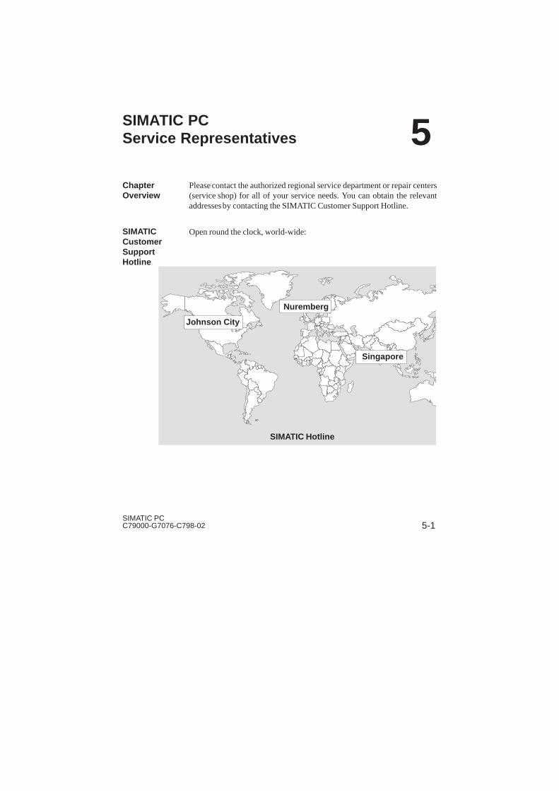
Please contact the authorized regional service department or repair centers(service shop) for all of your service needs. You can obtain the relevantaddresses by contacting the SIMATIC Customer Support Hotline.
Open round the clock, world-wide:
Johnson City
Nuremberg
Singapore
SIMATIC Hotline
ChapterOverview
SIMATICCustomerSupportHotline
5

English
5-2SIMATIC PC
C79000-G7076-C798-02
NurembergSIMATIC BASIC Hotline
Johnson CitySIMATIC BASIC Hotline
SingaporeSIMATIC BASIC Hotline
Local time:Mo.-Fr. 7:00 to 17:00
Phone: +49 (911) 895-7000
Fax: +49 (911) 895-7002
E-Mail: simatic.support@
nbgm.siemens.de
GMT: +1:00
Local time:Mo.-Fr. 8:00 to 17:00
Phone: +1 423 461-2522
Fax: +1 423 461-2289
E-Mail: simatic.hotline@
sea.siemens.com
GMT: –5:00
Local time:Mo.-Fr. 8:30 to 17:30
Phone: +65 740-7000
Fax: +65 740-7141
E-Mail: simatic@
singnet.com.sg
GMT +8:00
NurembergSIMATIC AuthorizationHotline
SIMATIC PremiumHotline
Local time:Mo.-Fr. 7:00 to 17:00
Phone: +49 (911) 895-7200
Fax: +49 (911) 895-7201
E-Mail: authorization@
nbgm.siemens.de
GMT +1:00
(Calls charged, only with
SIMATIC Card)
Time: Mo.-Fr. 0:00 to 24:00
Phone: +49 (911) 895-7777
Fax: +49 (911) 895-7001
GMT +01:00
The working languages of the SIMATIC Hotlines are generally English and German; theAuthorization Hotline can also be contacted in French, Italian, or Spanish.
The SIMATIC Customer Support team offers you substantial additionalinformation about SIMATIC products via its online services:
� General current information can be obtained from:
– the Internet under http://www.ad.siemens.de/simatic-cs
– the Fax-Polling number 08765-93 02 77 95 00
SIMATICCustomerSupportOnlineServices
SIMATIC PC Service Representatives

English
5-3SIMATIC PCC79000-G7076-C798-02
� Current product information leaflets and downloads which you mayfind useful are available:
– on the Internet underhttp://www.ad.siemens.de/support/html_00/
– via the Bulletin Board System (BBS) in Nuremberg (SIMATICCustomer Support Mailbox) under the number+49 (911) 895-7100.
To access the mailbox, use a modem with up to V.34 (28.8 Kbps) withparameters set as follows: 8, N, 1, ANSI; or dial in via ISDN (x.75, 64Kbps).
SIMATIC PC Service Representatives

English
5-4SIMATIC PC
C79000-G7076-C798-02
5.1 Regional Repair Centers
SIMATIC-Hotline
If problems occur, the SIMATIC Hotline should be able to help.
Siemens AG
AUT 1 CS
Gleiwitzerstr. 555
D-90475 Nürnberg-Moorenbrunn
Telefon: (49)911-895-7000
Fax: (49)911-895-7001
(49)911-895-7002
Region PG-Repair Center Phone
Augsburg ATD TD ABG 6 (0821)3252 599
Berlin ATD TD BLN 5 (030)386 34926Bielefeld ATD TD (0521)291 323
Bremen ANL TD 47 (0421)364 2996
Chemnitz A&D B 14 (0371)475 3860
Cologne ATD TD SSH 5 (0221)576 6516Erlangen ATD TD 3 LSE-ITC (09131)7 32714
Erlangen ATD TD 3 LSE-RC (09131)7 31048
Essen ATD TDE (0201)816 1580Frankfurt ANL TD 84 (069)797 7358
Fürth A&D SE B 9.1 (0911)750 2741
Hamburg ANL TD FSZ (040)2889 4230
Hanover ANL TD HVR 1 (0511)877 2241Karlsruhe A&D AS EWK PLZ 52 (0721)595 4183
Kassel ATD TD (0561)7886 434
Langen ATD TD E (069)797 5608
Leipzig ATD TD 31 (0341)210 2049Mannheim ATD TD 9 (0621)456 1328
Munich ATD TD MCH 53 (089)9221 6213
Nuremberg ATD TD S 1 (0911)654 6117Saarbrücken ATD TD 3 (0681)386 2598
Stuttgart Weilimdorf ATD TD SDW 5 (0711)137 6228
SIMATIC PC Service Representatives
English
5-5SIMATIC PCC79000-G7076-C798-02
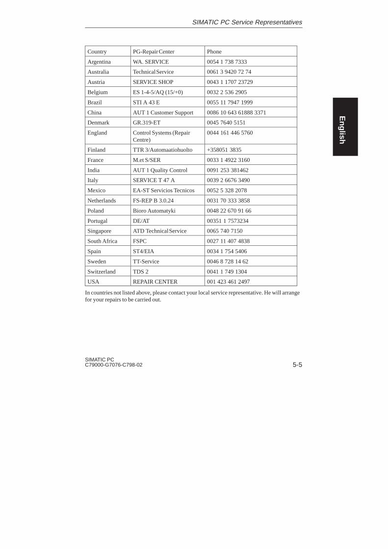
Country PG-Repair Center Phone
Argentina WA. SERVICE 0054 1 738 7333
Australia Technical Service 0061 3 9420 72 74
Austria SERVICE SHOP 0043 1 1707 23729
Belgium ES 1-4-5/AQ (15/+0) 0032 2 536 2905
Brazil STI A 43 E 0055 11 7947 1999
China AUT 1 Customer Support 0086 10 643 61888 3371
Denmark GR.319-ET 0045 7640 5151
England Control Systems (RepairCentre)
0044 161 446 5760
Finland TTR 3/Automaatiohuolto +358051 3835
France M.et S/SER 0033 1 4922 3160
India AUT 1 Quality Control 0091 253 381462
Italy SERVICE T 47 A 0039 2 6676 3490
Mexico EA-ST Servicios Tecnicos 0052 5 328 2078
Netherlands FS-REP B 3.0.24 0031 70 333 3858
Poland Bioro Automatyki 0048 22 670 91 66
Portugal DE/AT 00351 1 7573234
Singapore ATD Technical Service 0065 740 7150
South Africa FSPC 0027 11 407 4838
Spain ST4/EIA 0034 1 754 5406
Sweden TT-Service 0046 8 728 14 62
Switzerland TDS 2 0041 1 749 1304
USA REPAIR CENTER 001 423 461 2497
In countries not listed above, please contact your local service representative. He will arrangefor your repairs to be carried out.
SIMATIC PC Service Representatives

English
5-6SIMATIC PC
C79000-G7076-C798-02
SIMATIC PC Service Representatives

Index-1SIMATIC PCC79000-G7076-C798-02
Index
AAcrobat Reader
installation, 3-9, 3-10using, 3-11
Authenticity certificate, Windows95, 3-7
Authorized Maintenance and RepairCenters, 5-1
BBattery, safety instructions, 1-3
CCD-ROM drive, 3-13Chapter overview, authorized main-
tenance and repair centers, 5-1Clocktime in PC is incorrect, 4-7Connecting the supply voltage
monitor, 2-8system unit, 2-8
DDate in PC is incorrect, 4-7
Delivery contents, 2-1checking, 2-1unpacking, 2-1
EElectronic manual
Acrobat Reader, 3-8overview, 3-8technical description, 3-8user’s guide, 3-8
Electrostatically Sensitive Devices,1-4
Error messages, 4-11operating system, 4-1self-test, 4-13–4-16
ESD, 1-4
HHard disk drive, configuring
MS-DOS 6.22, 4-8Windows 95, 4-9
Hard drivedata deleted, 4-8reboot, 4-8
Index-2SIMATIC PC
C79000-G7076-C798-02
II/Os, connecting, 2-4Installation in a 19” cabinet or rack,
2-2
LLogbook, 2-1
MMains switch, 1-2Monitor
connecting the supply voltage,2-8
error message appears, 4-11remains dark, 4-4
Mouse pointer, does not appear onscreen, 4-6
MS-DOS, installation, 3-10
OOperating system
loading MS-DOS, 3-7loading Windows 95, 3-7
Operator elements on the front side,3-2
Operator inputs, Windows 95, 3-7
PPC
connecting, 2-4from other manufacturer, 4-3operating, 3-1setting up, 3-1setting up when operating system
is installed on hard disk, 3-6
RReset key, 3-3
SSafety instructions, battery, 1-3Screen display
does not appear, 4-5drifts, 4-5
Startup, 3-4Supply voltage, 1-2
connecting to the monitor, 2-8faulty, 4-2
System unit, connecting the supplyvoltage, 2-8
System unit ON, remains dark afterswitching on, 4-2
VVentilation slots, 1-1, 2-3
Index

1SIMATIC PC RI 25 PC79000-G7076-C798-02
Siemens AG
A&D AS E81
Oestliche Rheinbrueckenstr. 50
D–76181 Karlsruhe
Federal Republic of Germany
From:
Your Name: _ _ _ _ _ _ _ _ _ _ _ _ _ _ _ _ _ _ _ _ _ _ _ _ _ _
Your Title: _ _ _ _ _ _ _ _ _ _ _ _ _ _ _ _ _ _ _ _ _ _ _ _ _ _ _
Company Name:_ _ _ _ _ _ _ _ _ _ _ _ _ _ _ _ _ _ _ _ _ _ _ _ _
Street:_ _ _ _ _ _ _ _ _ _ _ _ _ _ _ _ _ _ _ _ _ _ _ _ _ _ _
City, Zip Code: _ _ _ _ _ _ _ _ _ _ _ _ _ _ _ _ _ _ _ _ _ _ _
Country: _ _ _ _ _ _ _ _ _ _ _ _ _ _ _ _ _ _ _ _ _ _ _ _ _
Phone: _ _ _ _ _ _ _ _ _ _ _ _ _ _ _ _ _ _ _ _ _ _ _ _ _ _
Please check any industry that applies to you:
� Automotive
� Chemical
� Electrical Machinery
� Food
� Instrument and Control
� Nonelectrical Machinery
� Petrochemical
� Pharmaceutical
� Plastic
� Pulp and Paper
� Textiles
� Transportation
� Other _ _ _ _ _ _ _

2SIMATIC PC RI 25 P
C79000-G7076-C798-02
Remarks Form
Your comments and recommendations will help us to improve the quality and use-fulness of our publications. Please take the first available opportunity to fill outthis questionnaire and return it to Siemens.
Please give each of the following questions your own personal mark within therange from 1 (very good) to 5 (poor).
1. Do the contents meet your requirements?
2. Is the information you need easy to find?
3. Is the text easy to understand?
4. Does the level of technical detail meet your requirements?
5. Please rate the quality of the graphics/tables:
Additional comments:
_ _ _ _ _ _ _ _ _ _ _ _ _ _ _ _ _ _ _ _ _ _ _ _ _ _ _ _ _ _ _ _
_ _ _ _ _ _ _ _ _ _ _ _ _ _ _ _ _ _ _ _ _ _ _ _ _ _ _ _ _ _ _ _
_ _ _ _ _ _ _ _ _ _ _ _ _ _ _ _ _ _ _ _ _ _ _ _ _ _ _ _ _ _ _ _
_ _ _ _ _ _ _ _ _ _ _ _ _ _ _ _ _ _ _ _ _ _ _ _ _ _ _ _ _ _ _ _
_ _ _ _ _ _ _ _ _ _ _ _ _ _ _ _ _ _ _ _ _ _ _ _ _ _ _ _ _ _ _ _
_ _ _ _ _ _ _ _ _ _ _ _ _ _ _ _ _ _ _ _ _ _ _ _ _ _ _ _ _ _ _ _
_ _ _ _ _ _ _ _ _ _ _ _ _ _ _ _ _ _ _ _ _ _ _ _ _ _ _ _ _ _ _ _
_ _ _ _ _ _ _ _ _ _ _ _ _ _ _ _ _ _ _ _ _ _ _ _ _ _ _ _ _ _ _ _