
SIMATIC NET Industrial Ethernet OMC - Siemens AG · SIMATIC NET Industrial Ethernet OMC ... •...
45
SIMATIC NET Industrial Ethernet OMC Operating Instructions Preface, Contents Introduction 1 Functions 2 Network Topologies with OMCs 3 Interfaces and Displays 4 Installation 5 Technical Specifications 6 Further Support 7 Notes on the CE Mark 8 Glossary 9 Index 10 References 11 Release 8 / 2001 C79000-G8976-C164-01
Transcript of SIMATIC NET Industrial Ethernet OMC - Siemens AG · SIMATIC NET Industrial Ethernet OMC ... •...
SIMATIC NET
Industrial EthernetOMC
Operating Instructions
Preface, Contents
Introduction 1
Functions 2
Network Topologies withOMCs
3
Interfaces and Displays 4
Installation 5
Technical Specifications 6
Further Support 7
Notes on the CE Mark 8
Glossary 9
Index 10
References 11
Release 8 / 2001
C79000-G8976-C164-01

Industrial Ethernet OMC2 C79000-G8976-C164-01
Classification of Safety-Related Notices
This document contains notices which you should observe to ensure your ownpersonal safety, as well as to protect the product and connected equipment. Thesenotices are highlighted in the manual by a warning triangle and are marked as followsaccording to the level of danger:
Danger
indicates that death or severe personal injury will result if proper precautions are nottaken.
! Warning
indicates that death or severe personal injury can result if proper precautions are nottaken.
! Caution
with warning triangle indicates that minor personal injury can result if properprecautions are not taken.
Caution
without warning triangle indicates that damage to property can result if properprecautions are not taken.
Notice
indicates that an undesirable result or status can occur if the relevant notice is ignored.
Note
highlights important information on the product, using the product, or part of thedocumentation that is of particular importance and that will be of benefit to the user.

Industrial Ethernet OMCC79000-G8976-C164-01 3
Trademarks
SIMATIC , SIMATIC NET and SINEC are registered trademarks of Siemens AG.
Third parties using for their own purposes any other names in this document whichrefer to trademarks might infringe upon the rights of the trademark owners.
Safety Instructions Regarding your Product
Before you use the product described here, read the safety instructions belowthoroughly.
Qualified Personnel
Only qualified personnel should be allowed to install and work on this equipment .Qualified persons are defined as persons who are authorized to commission, toground, and to tag circuits, equipment, and systems in accordance with establishedsafety practices and standards.
Correct Usage of Hardware Products
Please note the following regarding the correct usage of hardware products:
Caution
This device and its components may only be used for the applications described in thecatalog or the technical description, and only in connection with devices orcomponents from other manufacturers which have been approved or recommendedby Siemens.
This product can only function correctly and safely if it is transported, stored, set up,and installed correctly, and operated and maintained as recommended.
Before you use the supplied sample programs or programs you have written yourself,make certain that no injury to persons nor damage to equipment can result in yourplant or process.
EU Directive: Do not start up until you have established that the machine on which youintend to run this component complies with the directive 89/392/EEC.

Industrial Ethernet OMC4 C79000-G8976-C164-01
Prior to Startup
Before putting the product into operation, note the following warning:
Caution
Before installation and startup, read the instructions in the appropriate documentation.For ordering data of the documentation, please refer to catalogs or contact your localSiemens representative.

Industrial Ethernet OMC5 C79000-G8976-C164-01
Preface
Purpose of the Operating Instructions
These Operating Instructions support you when configuring, commissioning, andtroubleshooting networks including the Optical Media Converters OMC TP11 andOMC TP11-LD.
The Package
The OMC includes the following components:
• OMC device
• 6-pin plug-in terminal block
• Fittings (fixing brackets, screws) for wall mounting or installation in a 19" cabinet
• Product Information
Mounting the OMC
Follow the instructions in Chapter 5 of these operating instructions.
Validity of the Operating Instructions
These operating instructions are valid for the following devices:
• OMC TP11
• OMC TP11-LD

Preface
Industrial Ethernet OMC6 C79000-G8976-C164-01
Further Documentation
The "SIMATIC NET Industrial Ethernet Twisted Pair and Fiber Optic Networks"manual contains information on other SIMATIC NET products that you can operatein conjunction with OMCs in an Industrial Ethernet network.
You can download this manual from Customer Support on the Internet under entrynumber 1172207:
http://www4.ad.siemens.de/view/cs/de/1172207
Finding Information
To help you to find information quickly, the appendix includes the following sectionsin addition to the table of contents:
• Glossary
• Index
Guide to the Manual
To help you to find specific information quickly, these operating instructions includethe following parts:
• At the front of the operating instructions you will find a complete table ofcontents.
• The chapters have headings in the left margin with an overview of the contentsof the paragraphs in the section.
• Following the appendix, you will find a Glossary in which the most importantspecialist terms used in the instructions are defined.
• At the back of the operating instructions, you will find an index with which youcan find topics quickly.
Audience
These Operating Instructions are intended for persons involved in configuring,commissioning, and troubleshooting networks including the OMC TP11 andOMC TP11-LD.

Preface
Industrial Ethernet OMCC79000-G8976-C164-01 7
Personnel Qualification Requirements
Only qualified personnel should be allowed to install and work on this equipment.Qualified personnel as referred to in the operating instructions or in the warningnotes are defined as persons who are familiar with the installation, assembly,startup and operation of this product and who possess the relevant qualifications fortheir work, e.g.:
• Training in or authorization for connecting up, grounding or labeling circuits anddevices or systems in accordance with current standards in safety technology;
• Training in or authorization for the maintenance and use of suitable safetyequipment in accordance with current standards in safety technology;
• First Aid qualification.
Standards and Approvals
The OMC meets the requirements for the CE mark. For more detailed informationabout approvals and standards, refer to the appendix.

Industrial Ethernet OMC8 C79000-G8976-C164-01
Contents
1 Introduction .....................................................................................................................9
1.1 OMC TP11..........................................................................................................10
1.2 OMC TP11-LD....................................................................................................12
2 Functions .......................................................................................................................13
3 Network Topologies with OMCs ..................................................................................14
4 Interfaces and Displays ................................................................................................18
4.1 TP Port ...............................................................................................................19
4.2 FO Port ...............................................................................................................21
4.3 Signaling Contact and Power Supply .................................................................22
4.4 Displays ..............................................................................................................24
5 Installation and Maintenance .......................................................................................25
5.1 Components of the Product................................................................................26
5.2 Installation...........................................................................................................27
5.3 Cleaning..............................................................................................................32
5.4 Maintenance .......................................................................................................33
6 Technical Specifications ..............................................................................................34
7 Further Support .............................................................................................................37
8 Notes on the CE Mark ...................................................................................................41
9 Glossary .........................................................................................................................43
10 Index ............................................................................................................................44
11 References .....................................................................................................................45

Industrial Ethernet OMC9 C79000-G8976-C164-01
Introduction
1The OSM/ESM V2 (/5/) product generation allows you to structure powerful FastEthernet networks in an industrial environment. However, nodes can only beattached to the network over twisted-pair ports; in other words electrically.
To remove this restriction, the OSM/ESM product range has been expanded withthe addition of the OMC TP11 and OMC TP11-LD media converters. The OMCsopen up new areas of application, such as:
• FO right up to the machine:Fast FO node attachment (100 Mbps full duplex) over FO ports of the OSMsand media converters in areas with high levels of electromagnetic interference.
• Spanning of long distances (LD, long-distance):FO cable sections up to 26 km to a single remote station.

Introduction
Industrial Ethernet OMC10 C79000-G8976-C164-01
1.1 OMC TP11
Possible Attachments
• A network component, such as an ESM electrical switch module or a DTE overthe twisted-pair port (RJ-45 socket)
• A network component, such as an OSM optical switch module or a DTE over asecond OMC at the optical port (2 BFOC sockets)
Figure 1: OMC TP11

Introduction
Industrial Ethernet OMCC79000-G8976-C164-01 11
Properties of the OMC TP11
Electrical port 100 Mbps (full duplex)
TP connector technology (RJ-45 socketwith MDI-X Pinning (MediumDependent Interface-Cross Over))
Max. cable length 6 m (TP Cord or TPXP Cord)
Optical port 100 Mbps FO ports (full duplex)
BFOC female connectors
Maximum distance between two OMCTP11 modulesor to an OSM ITP62-LD
3000 m (multimode graded-index fiber)

Introduction
Industrial Ethernet OMC12 C79000-G8976-C164-01
1.2 OMC TP11-LD
Possible Attachments
The OMC TP11-LD is suitable for spanning extremely long distances. With themonomode fiber, distances up to 26 km between two OMC TP11-LD or between anOMC TP11-LD and OSM ITP62-LD can be spanned.
Properties of the OMC TP11-LD
Electrical port 100 Mbps (full duplex)
TP attachment technology (RJ-45socket with MDI-X Pinning (MediumDependent Interface-Cross Over))
Max. cable length 6 m (TP Cord or TPXP Cord)
Optical port 100 Mbps FO ports (full duplex)
BFOC female connectors
Maximum distance between two
OMC TP11-LD
26 km (monomode fiber)
Note
The OMC TP11-LD can only be linked with the OMC TP11-LD or OSM ITP62-LDover its optical port.Linking the optical port with an OMC TP11, OSM ITP62, OSM ITP53 or OSM TP62is not permitted.
Industrial Ethernet OMC13 C79000-G8976-C164-01
Functions
2Converting between 100BaseTX and 100BaseFX
The OMC is used to link standard 100BaseTX Ethernet over twisted-pair (TP) cableand 100BaseFX Ethernet over FO cable. All data is forwarded transparently fromthe optical port to the electrical port and vice versa.
Notice
The devices attached to OMCs must support 100 Mbps and full duplex.
Setting the Transmission Rate or Duplex Mode
• An OMC is connected optically to an OSM FO port:In this configuration, if the device connected to the TP interface of the OMC iscapable of autonegotiation and the full duplex mode, the device is configuredautomatically for 100 Mbps and full duplex. Using components of the OSMfamily and devices capable of autonegotiation and full duplex makes a plug-and-play configuration possible.
• Two OMCs are interconnected over an FO cable:If two devices with activated autonegotiation are connected to the two OMCs,the autonegotiation procedure taking place at both ends at the same time mayprevent a link from being established. To prevent this, one or both of the TPdevices must be permanently set to 100 Mbps and full duplex.
Link Fault Transfer
The link status of the FO link is transferred to the TP port and vice versa.
This means that the OMC can also be used in redundant rings or in standbysections for the redundant linking of subnets.

Industrial Ethernet OMC14 C79000-G8976-C164-01
Network Topologies with OMCs
3
Using the media converters OMC TP11 and OMC TP11-LD, the followingapplications can be implemented.
Attachment of Individual Remotely Located DTEs over OMC-FOC-OMC to aTwisted-Pair Network
100 MbpsTP XP Cordmax. 6 m
OMC
100 Mbpsfiber-opticmax. 3 km / 26 km
100 MbpsTP Cordmax. 6 m
OMC
ESM
ESM
S7-400S7-300
10/100 Mbpsmax. 100 m
PC
Notice
Since two OMCs are connected over FO cable, one of the two TP devices (in thefigure: S7-400 CP or ESM port to the OMC) must be permanently set to 100 Mbpsand full duplex.

Network Topologies with OMCs
Industrial Ethernet OMCC79000-G8976-C164-01 15
Attachment of Remotely Located Subnets over OSM-FOC-OMC to a Twisted-PairNetwork
10/100 Mbpsmax. 100 m
ESM
OSM
OMC
S7-400 S7-300
ESM
PC
100 MbpsTP XP Cordmax. 6 m
100 Mbpsfiber-opticmax. 3 km / 26 km
10/100 Mbpsmax. 100 m
The ESM port to the OMC sets itself automatically to 100 Mbps and full duplex.Manual setting of the ESM port to the OMC is not necessary.
Network Topologies with OMCs
Industrial Ethernet OMC16 C79000-G8976-C164-01
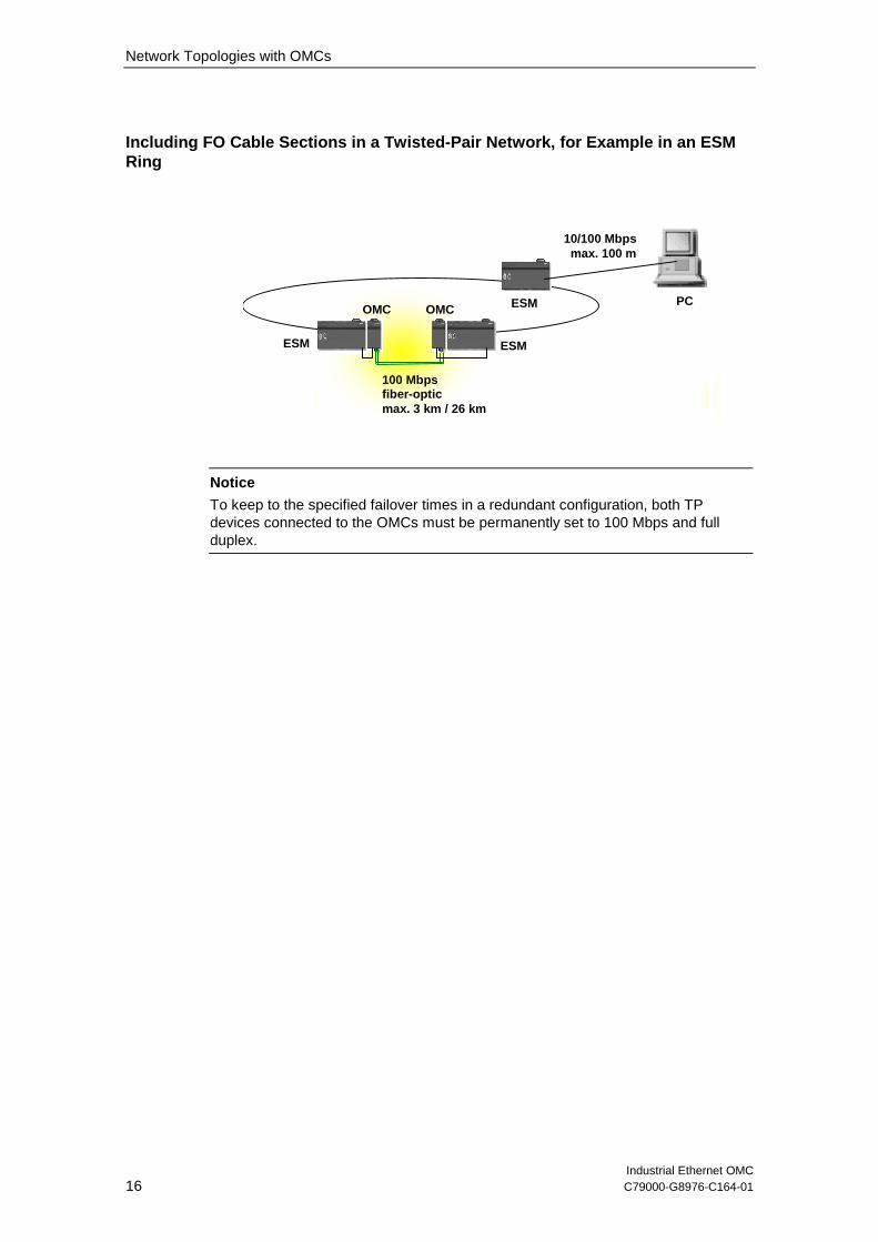
Including FO Cable Sections in a Twisted-Pair Network, for Example in an ESMRing
100 Mbpsfiber-opticmax. 3 km / 26 km
10/100 Mbpsmax. 100 m
ESMESM
ESMOMCOMCPC
Notice
To keep to the specified failover times in a redundant configuration, both TPdevices connected to the OMCs must be permanently set to 100 Mbps and fullduplex.

Network Topologies with OMCs
Industrial Ethernet OMCC79000-G8976-C164-01 17
Redundant Linking of OSM/ESM Subnets Located a Long Distance Apart overOMC TP11 or OMC TP11-LD
OMCTP11-LD
OMCTP11-LD
Stby cable
OSM/ESM ring 1
OMCTP11-LD
OMCTP11-LD
OSM/ESM ring 2
OSM/ESM inStby mode
Fiber-optic100 Mbpsmax. 26 km
Notice
To keep to the specified failover times in a redundant configuration, all TP devicesconnected to the OMCs must be permanently set to 100 Mbps and full duplex.

Industrial Ethernet OMC18 C79000-G8976-C164-01
Interfaces and Displays
4

Interfaces and Displays
Industrial Ethernet OMCC79000-G8976-C164-01 19
4.1 TP Port
Pinning
On the OMC, the TP port is implemented as an RJ-45 with MDI-X Pinning (MediumDependent Interface-Cross Over) socket.
Notice
TP Cords or TP-XP Cords with a maximum length of 6 m can be connected to theTP port. Other attachments (connections via outlets, longer TP Cords) are notpermitted.
Link Control
The attached cable segments are monitored according to the 100BASETXstandard for short circuits or wire breaks. A fault on the link is signaled by the portstatus displays of the OMC and of the devices connected to the TP and FO ports.
Duplex Mode
The OMC is capable of full duplex mode; in other words data can be transferred inboth directions at the same time. The optical interfaces of the OMC also operate infull duplex mode so that TP devices connected to these ports must also be set tothis mode.
Note
Both devices connected to the OMC (FO and TP) must be set to full duplex mode.If the devices do not support autonegotiation, full duplex mode must be configuredmanually.
Autonegotiation
Using the autonegotiation mechanism according to the IEEE standard 802.3, a TPdevice capable of autonegotiation and full duplex is automatically set to 100 Mbpsand full duplex.

Interfaces and Displays
Industrial Ethernet OMC20 C79000-G8976-C164-01
Note
• It is not possible to link two OMCs over their TP interfaces.
• The OMC can be used along with products of the OSM/ESM family inredundant rings or in standby links (see Network Topologies OMC, Part 3). Tokeep to the specified failover times in a redundant configuration, both TPdevices connected to the OMCs must be permanently set to 100 Mbps and fullduplex.
• If two OMCs are interconnected over an FO cable and if two devices withactivated autonegotiation are connected over their TP ports, theautonegotiation procedure taking place at both ends at the same time mayprevent a link from being established. To prevent this, one or both of the TPdevices must be permanently set to 100 Mbps and full duplex.

Interfaces and Displays
Industrial Ethernet OMCC79000-G8976-C164-01 21
4.2 FO Port
The FO port has a BFOC/2.5(ST) female connector. The connected cable ismonitored for wire breaks complying with the IEEE 802.3 100BaseFX standard. Abreak on the FO cable is always signaled by the port status displays of the OMCand of the two attached devices. (Status LED of the port goes off).

Interfaces and Displays
Industrial Ethernet OMC22 C79000-G8976-C164-01
4.3 Signaling Contact and Power Supply
The attachment of the power supply and the signaling contact is made using a 6-pinplug-in terminal block with a screw securing mechanism.
L1 +
F1
M
M
F2
L2 +
+24V DC
+24V DC
Figure 2: Terminal Block
! Warning
Industrial Ethernet OMCs are designed for operation with safety extra-low voltage.This means that only safety extra-low voltages (SELV) complying withIEC950/EN60950/ VDE0805 can be connected to the power supply terminals andthe signaling contact.
The power supply unit to supply the OMC must comply with NEC Class 2 (voltagerange 18 - 32 V, current requirement 1 A)
The signaling contact can carry a load of maximum 100 mA (safety extra-lowvoltage (SELV), DC 24V).

Interfaces and Displays
Industrial Ethernet OMCC79000-G8976-C164-01 23
Power Supply
The power supply can be connected redundantly. Both inputs are isolated. There isno load distribution. With redundant power supply, the power supply unit with thehigher output voltage supplies the OMC alone. The power supply is connected overa high resistance with the enclosure to all an ungrounded setup.
Signaling Contact
The following is signaled via a floating signaling contact (relay contact) whencontact is broken:
• The failure of one or both power supplies.
Notice
Both power supplies are always monitored (L1 and L2). If only one power supplyexists, this must be applied via L1 and L2 otherwise the signaling contact willsignal an error.
• The incorrect link status of a port (in other words, the port is not correctlyattached or there are no link test pulses coming from the partner device).

Interfaces and Displays
Industrial Ethernet OMC24 C79000-G8976-C164-01
4.4 Displays
Fault display (red LED)
Status Meaning
On The OMC has detected an error. The signaling contact opensat the same time. The signaled errors are described inChapter 4.3.
Off No errors detected by the OMC.
Power display (green LEDs)
The status of the redundant power supply is signaled by two green LEDs:
Status Meaning
On Power supply L1 or L2 is connected
Off Power supply L1 or L2 is not connected or <14 V
Port status display (green/yellow LEDs)
The status of the ports is signaled by two LEDs:
Status Meaning
Port 1 LED green TP link exists, no data reception
Port 1 LED yellow TP link exists, receiving data at TP port
Port 1 LED off No TP link exists
Port 2 LED green FO link exists, no data reception
Port 2 LED yellow FO link exists, receiving data at FO port
Port 2 LED off No FO link exists

Industrial Ethernet OMC25 C79000-G8976-C164-01
Installation and Maintenance
5

Installation and Maintenance
Industrial Ethernet OMC26 C79000-G8976-C164-01
5.1 Components of the Product
Unpacking, Checking the Consignment
1. Check that the consignment includes the following components:
– OMC device
– Mounting brackets, screws and terminal block
– Product Information
2. Check each component for any damage.
! Warning
Do not install damaged components!

Installation and Maintenance
Industrial Ethernet OMCC79000-G8976-C164-01 27
5.2 Installation
There are several ways of installing the OMC:
• Installation on a 35 mm standard rail
• Installation on a SIMATIC S7-300 rail
• Installation in a 19" cabinet (along with other OMCs and OSMs/ESMs)
• Wall mounted
Note
• Remember that the OMC must only be installed horizontally (ventilation slitstop/bottom see Figure 4). To ensure adequate convection, there must be aclearance of at least 5 cm above and below the ventilation slits. You shouldalso make sure that the permitted ambient temperature range is not exceeded.
• The optical transmitter and receiver elements are sensitive to contamination.You should therefore only remove the dust protection caps from the BFOCsockets immediately before plugging in the FO connector.If you remove the connector, cover the sockets immediately with the dustprotection caps.
• During installation and operation, make sure that you adhere to the installationinstructions and safety-related notices in this description and in the SIMATICNET Industrial Twisted Pair and Fiber-Optic Networks manual /2/.
Preparations
Remove the terminal block from the OMC and wire up the power supply and signallines as described in Section 4.3.

Installation and Maintenance
Industrial Ethernet OMC28 C79000-G8976-C164-01
Standard Rail Mounting
1. Install the OMC on a 35 mm standard rail complying with DIN EN 50022.
2. Fit the OMC on to the rail from above and press in the bottom of the deviceuntil the catch engages.
3. Connect the electrical and optical cables and the terminal block for the powersupply.
Figure 3: Installing the OMC on a DIN Standard Rail

Installation and Maintenance
Industrial Ethernet OMCC79000-G8976-C164-01 29
Removing from a Standard Rail
To remove the OMC from the rail, first disconnect the FO and TP cables and pulloff the terminal block.Then pull down the device and release it from the rail.
Figure 4. Removing from the Standard Rail

Installation and Maintenance
Industrial Ethernet OMC30 C79000-G8976-C164-01
Installation on a SIMATIC S7-300 Rail
1. First fix one of the two supplied brackets to the right (OMC mounted on theright) or the left (OMC mounted on the left) side of the OMC.
2. Fit the guide on the top of the OMC casing into the S7 rail.
3. Screw the OMC to the bottom of the standard rail.
Installation in a 19" Cubicle
To install in the 19" cubicle, you require the two securing brackets supplied. Youcan achieve the 19'' width
• with eight OMCs
• with one OSM / ESM and four OMCs
Follow the steps outlined below:
1. First screw the OMCs or ESMs/OSMs to the supplied mounting plates at therear.
2. Fit two of the supplied brackets to the sides
3. Secure the devices using the brackets in the 19" cubicle. Please note that theOMC must be grounded with low resistance via the two holding brackets.
Note
To install in a 19'' cubicle, you require a Torx screwdriver size T10 x 80.

Installation and Maintenance
Industrial Ethernet OMCC79000-G8976-C164-01 31
Wall Mounting
To install an OMC on a wall, follow the steps below:
1. Fit the supplied mounting brackets on the sides of the OMC.
2. Secure the device to the wall using the brackets.
3. Connect the device to protective earth with a low-resistance connection viaone of the brackets.
The table below shows how to secure the module depending on the wall type.
Wall Type Mounting
Concrete wall Use four wall plugs 6 mm in diameter 30 mm long(drillhole 6 mm diameter, 45 mm deep).Use screws 4.5 mm in diameter and 40 mm long.
Metal wall
(min. 2 mm thick)
Use screws 4 mm in diameter and at least 15 mmlong.
Sandwich type plaster wall
(min. 15 mm thick)
Use an anchoring plug with at least4 mm diameter.
Note
The module must be secured to the wall so that the mounting can carry at leastfour times the weight of the module.

Installation and Maintenance
Industrial Ethernet OMC32 C79000-G8976-C164-01
5.3 Cleaning
The OMC casing can be cleaned, when necessary with a dry cloth.

Installation and Maintenance
Industrial Ethernet OMCC79000-G8976-C164-01 33
5.4 Maintenance
If a fault develops, please send the module to your SIEMENS service departmentfor repair. The devices cannot be repaired on site.

Industrial Ethernet OMC34 C79000-G8976-C164-01
Technical Specifications
6Attachments
Attachment of DTEs or NetworkComponents over Twisted Pair
1 x RJ-45 with MDI-X Pinning (MediumDependent Interface-Cross Over) onOMC TP11 and OMC TP11-LD
The ports operate at 100 Mbps, fullduplex (100BaseTX)
Attachment of other networkcomponents or OMCs over FO cable
2 BFOC sockets on the OMC TP11and OMC TP11-LD(100 Mbps, full duplex complying with100BaseFX)
Connector for power supply andsignaling contact
1 x 6-pin plug-in terminal block
Electrical Data
Power supply(redundant inputs isolated)
2 supplies DC 24 V(DC 18 to 32 V)safety extra-low voltage (SELV)
Power loss at DC 24 V 3.6 W
Load on the signaling contact DC 24 V / max. 1000 mA safety extra-low voltage (SELV)
Current consumption at rated voltage 150 mA
Overcurrent protection at input PTC resettable fuse (0.6 A / 60 V)

Technical Specifications
Industrial Ethernet OMCC79000-G8976-C164-01 35
Permitted Cable Lengths
FO link between two OMCs OMC TP11:
0-3000m (62.5/125 µm or 50/125µmglass fiber; 1 dB/km at 1300 nm; 600MHz*km; 6 dB max. permitted FOcable attenuation at 3 dB link powermargin)
OMC TP11-LD:
0-26000m (10/125 µm monomodefiber; 0.5 dB/km at 1300 nm; 13 dBmax. permitted FO cable attenuation at2 dB
TP Connection 0-6 m with TP cord
Permitted Ambient Conditions/EMC
Operating temperature 0°C to +60°C
Storage/transport temperature -40°C to +80°C
Relative humidity in operation ‹ 95% (no condensation)
Operating altitude Max. 2000 m
Noise emission EN 55081 Class A
Noise immunity EN 50082-2
Degree of protection IP 20
Laser protection Class 1 complying with IEC 60825 –1

Technical Specifications
Industrial Ethernet OMC36 C79000-G8976-C164-01
Mechanical Design
Dimensions (W x H x D) in mm 54 x 136.5 x 69
Weight in g 500
Installation options Standard rail
S7-300 rail
Wall mounted
Installation in 19” cubicle
Only horizontal installationpermitted
(ventilation slits top/bottom)
Product and Ordering Data
OMC TP11 and OMC TP11-LD • OMC device
• Mounting brackets, screws andterminal block
• Product Information
Order numbers:
OMC TP11 6GK1100-2AB00
OMC TP11-LD 6GK1100-2AC00
“Industrial Twisted Pair and Fiber OpticNetworks” Manual
6GK1970-1BA10-0AA1

Industrial Ethernet OMC37 C79000-G8976-C164-01
Further Support
7Who to Contact
If you have technical questions about using the described product and your problemis not dealt with in the documentation or in the integrated help system, pleasecontact your Siemens representative or dealer.
You will find the addresses:
• in our catalog IK PI
• on the Web (http://www.ad.siemens.de/net)

Further Support
Industrial Ethernet OMC38 C79000-G8976-C164-01
Automation and Drives, Service & Support
Service & Support from A&D is available round the clock worldwide.
The languages spoken are German and English.French, Italian, and Spanish are also spoken on the authorization hotline.
Technical Support Authorization Hotline
Europe and Africa (Nuremberg)Mo. To Fr. 7:00 to 17:00 (local time, GMT +1)Phone: +49 – (0) 180 – 5050 – 222Fax: +49 – (0) 180 – 5050 – 223E-mail: [email protected]
Europe and Africa (Nuremberg)Mo. To Fr. 7:00 to 17:00 (local time, GMT +1)Phone: +49 – (0) 911 – 895 – 7200Fax: +49 – (0) 911 – 895 – 7201E-mail: [email protected]
America (Johnson City)Mo. To Fr. 8:00 to 19:00 (local time, GMT –5)Phone: +1 – (0) 423 – 262 – 2522Fax: +1 – (0) 423 – 262 – 2231E-mail: [email protected]
Asia and Australia (Singapore)Mo. To Fr. 8:30 to 17:30 (local time, GMT +8)Phone: +65 – (0) 740 – 7000Fax: +65 – (0) 740 – 7001E-mail: [email protected]
SIMATIC Premium Hotline
Worldwide (Nuremberg)Workdays0:00 to 24:00 (local time, GMT +1)Phone: +49 – (0) 911 – 895 – 7777Fax: +49 – (0) 911 – 895 – 7001E-mail: [email protected]
Fast callbackguaranteed within a maximum of two hours(charged, only with the SIMATIC Card)
Johnson City Nuremberg
SingaporeSingapore
Service & Support

Further Support
Industrial Ethernet OMCC79000-G8976-C164-01 39
Service & Support on the Internet
On the World Wide Web, you will find the very latest information on the entireSIMATIC product range, for example, answers to frequently asked questions(FAQs), Tips and Tricks, software updates, and user information.
In addition to this free information, you can also order the following, for which acharge is made:
• Software products
• Sample application programs
These are charged to the SIMATIC CARD.
Internet address:http://www.siemens.de/automation/service&support
You can also formulate a question for the SIMATIC Knowledge Manager that willfind the solution in the knowledge database.
If you are working in an area without an online connection, part of the freeinformation area is available on the “SIMATIC Customer Support Knowledge Base”CD.

Further Support
Industrial Ethernet OMC40 C79000-G8976-C164-01
Training for SIMATIC NET
Who to Contact about Training Courses:
Siemens AGTrainings-Center für Automatisierungs- und AntriebstechnikA&D PT 49 Kursbüro
Östliche Rheinbrückenstraße 5076181 KarlsruheGermany
Phone: +49 – (0) 721 – 595 – 2917Fax: +49 – (0) 721 – 595 – 6087Internet: http://www.sitrain
Certification
The products of SIMATIC NET are manufactured and marketed using a qualitymanagement system complying with DIN ISO 9001 and certified by DQS (certificateregistration no. 2613). The DQS certificate is recognized in all IQNet countries(Reg. No. 2613).

Industrial Ethernet OMC41 C79000-G8976-C164-01
Notes on the CE Mark
8Product name:
SIMATIC NET OMC TP11 6GK1100-2AB00
OMC TP11-LD 6GK1100-2AC00
The SIMATIC NET products listed above meet the requirements of the following EUdirectives:
EMC Directive
Directive 89/336/EEC “Electromagnetic Compatibility”
Area of Application
The products are designed for use in an industrial environment:
RequirementsArea of Application
Noise emission Noise immunity
Industry EN 50081-2 : 1993 EN 50082-2 : 1995
Installation Guidelines
• The products meet the requirements if you adhere to the installation and safetyinstructions contained in this description and in the “SIMATIC NET IndustrialEthernet TP and Fiber-Optic Networks” manual.

Notes on the CE Mark
Industrial Ethernet OMC42 C79000-G8976-C164-01
Conformity Certificates
The EU declaration of conformity is available for the responsible authoritiesaccording to the above-mentioned EU directive at the following address:
Siemens AktiengesellschaftBereich Automatisierungs- und AntriebstechnikIndustrielle Kommunikation (A&D PT2)Postfach 4848D-90327 NürnbergGermany
Notes for the Manufacturers of Machines
This product is not a machine in the sense of the EU directive on machines. Thereis therefore no declaration of conformity for the EU directive on machines89/392/EEC.
If the product is part of the equipment of a machine, it must be included in theprocedure for obtaining the declaration of conformity by the manufacture of themachine.

Industrial Ethernet OMC43 C79000-G8976-C164-01
Glossary
9Autonegotiation Procedure standardized by IEEE 802.3 in which the transmission
parameters (for example 10/100 Mbps, full/half duplex) are negotiatedautomatically between the devices.
Autosensing See Autonegotiation
BFOC Bayonet Fiber-Optic Connector (ST-compatible).
EMC Electromagnetic compatibility
ESM Electrical Switching Module. SIMATIC NET Ethernet switch withelectrical ports
FOC Fiber-optic cable
LD Long Distance
MDI-X MDI-X Pinning (Medium Dependent Interface-Cross Over)
OMC Optical Media Converter
OSM Optical Switching Module. SIMATIC NET Ethernet switch with opticaland electrical ports
Signaling contact Floating relay contact via which the error states detected by the OMCcan be signaled.
TP Port Twisted-pair port

Industrial Ethernet OMC44 C79000-G8976-C164-01
Index
10AAmbient conditions, permitted..................35Attachments .............................................34Authorization hotline.................................38
CCable lengths, permitted ..........................35Customer Support ....................................38
DDesign, mechanical..................................36Displays..............................................18, 24
EElectrical data...........................................34
FFO ports ...................................................21
IInstallation in cubicle Schrank ..................30Installation, S7-300 rail.............................30Interfaces .................................................18
LLink control ...............................................19
MMounting, standard rail ............................ 28
NNetwork Topologies ................................. 14
OOMC TP11............................................... 10OMC TP11-LD......................................... 12
PPower supply ........................................... 23Product and ordering data ....................... 36
SSignaling contact ..................................... 23
TTechnical specifications........................... 34Technical Support.................................... 38TP port ..................................................... 19
WWall mounting.......................................... 31

Industrial Ethernet OMC45 C79000-G8976-C164-01
References
11/1/ SIMATIC NET Industrial Ethernet OSM/ESM Network Management,
Release 08/2001Available athttp://www4.ad.siemens.de/view/cs/de/8677203on the Web.
/2/ SIMATIC NET Industrial Twisted Pair and Fiber-Optic Networks, Release 05/2001Order numbers:6GK1970-1BA10-0AA0 German6GK1970-1BA10-0AA1 English6GK1970-1BA10-0AA2 French6GK1970-1BA10-0AA4 Italian
/3/ SINEC H1 Manual for Triaxial Networtks, Release 04Order number 6GK1970-1AA20-0AA0 (German/English)