SIM University 2012 - Christie · SIM University 2012 Glass Mirror Technology that is Reliable,...
22
SIM University 2012
Transcript of SIM University 2012 - Christie · SIM University 2012 Glass Mirror Technology that is Reliable,...

SIM University 2012

SIM University 2012
Glass Mirror Technology that is Reliable, Cost Effective & Versatile
October 23, 2012
Justin KnaplundChief Scientist, FlightSafety Displays, Austin, TX
2

Discussion Outline• History of Large Glass & Film
Cross-cockpit Mirrors• Glass versus Film Mirror
Characteristics• Mirror Shape• Localized radii deviations• Edge Roll Off• Training Tasks Sensitive to
Mirror Distortions
• Field of view• Impact Durability• Mirror Trim Cuts• Cleaning and Maintenance• Weight and footprint • Mirror Seams• Summary
SIM UniversityOctober 23, 20123

Large cross-cockpit collimated mirror history
SIM UniversityOctober 23, 20124
Ad from ICAO Bulletin, May 1987Early 80’s: Rediffusion WIDE Film Mirror, Singer Link Miles AWARDS glass mirror (3 overlapping segments), McDonnell Douglas Multiview filmLate 80’s: Acrylic and other rigid mirror development efforts (Singer Link, CAE, Evans & Sutherland and Rediffusion), SEOS film mirror developmentMid 90’s: Pilkington Aerospace glass mirror development (C-130, F-18, Blackhawk)2001: Glass Mountain Optics (GMO) acrylic mirror for containerized CH-472007: GMO uses glass mirrors for CH-472008: GMO produces 7 segment, 45° x 300° FOV glass mirror system for Rockwell-Collins E-2D2012: FSI-Displays delivers first motion-based 60° x 220° glass system for FSI S-76D2013: FSI-D to deliver first motion-based 60° x 290° glass system for USCG HC-144

Optical design relies on ideal mirror shape
SIM UniversityOctober 23, 20125

Mirror Shape Creation
SIM UniversityOctober 23, 20126
Glass: • ½” thick substrate• Ground, polished and coated• Radius tolerance = 0.5% of radius• Mirrors produced in radius-matched sets (within
0.5% of each other)• “Blur circle” = 1” diameter or less
Mylar (shown before vacuum): • Aluminized Polyester Film• Shaped by stretching over a hollow mirror cell with
film clamped or taped around edges and applying vacuum.
• Tension in the mirror film is higher vertically than horizontally
• Horizontal tension is higher in center than along the top/bottom
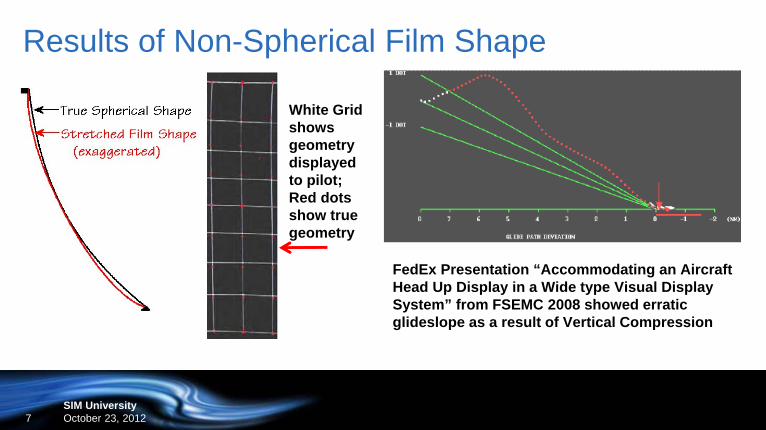
Results of Non-Spherical Film Shape
SIM UniversityOctober 23, 20127
FedEx Presentation “Accommodating an Aircraft Head Up Display in a Wide type Visual Display System” from FSEMC 2008 showed erratic glideslope as a result of Vertical Compression
White Grid shows geometry displayed to pilot; Red dots show true geometry

Localized Radius Deviations in Mylar Mirrors
SIM UniversityOctober 23, 20128
Localized Blur Circle Deviations in film mirrors can be caused by: • Polyester film not of uniform
thickness throughout the mirror• Aluminized mirror coating is not of
uniform thickness• Film not attached to the edges of
the mirror cell in uniform tension
Results of localized deviations:• Image “swim” due to zonal image magnification changes• Star field accelerations; more noticeable in pilot’s peripheral vision

Image Roll Off around edges of Mylar Mirror
SIM UniversityOctober 23, 20129
Mylar/film mirror images are prone to edge roll-off at the top, bottom and sides, distorting the image. Results:•Ground rush from image acceleration results in hard landings.•Bent runway edges and lines make judging height difficult, resulting in overshooting the touch down point.•Top edge distortions make air refueling challenging since tanker references are altered.•“S”-shaped horizon detracts from scene realism.

Glass Mirrors do not suffer edge distortion
SIM UniversityOctober 23, 201210
Glass mirror image is undistorted out to mirror edge, and retains spherical shape across entire image.

Glass Mirror Systems Horizontal FOV is not limited
SIM UniversityOctober 23, 201211
45° x 300° FOV glass system with 7 mirror segments.Glass mirror systems can have as many segments as needed to meet horizontal FOV.

Mylar Limited by 145”W Material Width Availability
SIM UniversityOctober 23, 201212
Film mirror FOV is limited by polyester film width maximum of 145”. FOVs beyond 60° x ~210° require “splicing” additional Mylar.

Glass Mirror Durability (with proper backing)
SIM UniversityOctober 23, 201213
Test of Phillips screwdriver drop on uncoated glass mirror (VIDEO)
Mirror impact testing
result, 4’ drop

Glass Mirror Custom mirror cuts
SIM UniversityOctober 23, 201214
Forward and quarter mirrors trimmed for cockpit nose clearance
Multiple mirrors trimmed to expand FOV of collimated display beyond 60º
using real image chin and side displays

Glass Mirror Cleaning and Maintenance
SIM UniversityOctober 23, 201215
Oily residue spread on surface of spherical glass mirror
After cleaning, the mirror was restored to its original condition with no damage to the mirror surface
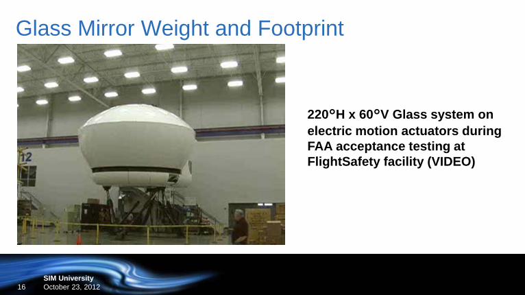
Glass Mirror Weight and Footprint
SIM UniversityOctober 23, 201216
220°H x 60°V Glass system on electric motion actuators during FAA acceptance testing at FlightSafety facility (VIDEO)

Glass Mirror Seams
SIM UniversityOctober 23, 201217
Customer video of 300°H x 45°V FOV E-2D fixed base flight simulator consisting of 7 glass mirror segments

Glass Mirror Seams
SIM UniversityOctober 23, 201218
• When viewing seams from 2 eyes, a different part of the scene will be obscured for each eye, so no information will be lost.
• Seam width is ~0.06”, or ~2 arc-minutes from PEP, which is less than half the pixel resolution of typical commercial flight simulator displays.
• These seams are closer to the pilot than the collimated scene being displayed and so are not in focus during flight training (“bug on the windscreen” phenomena)

Summary of Glass versus Mylar Characteristics
SIM UniversityOctober 23, 201219
Characteristic AdvantageSpherical shape & lack of distortion Glass
Wide Field of View Glass
Impact Durability Glass
Trim Cuts Glass
Cleaning Glass
Display Weight Mylar
Seams Mylar

“Bonus Question” – why use 11’R vs 10’R Mirrors?
SIM UniversityOctober 23, 201220
BP Screen Obscuration: What happens when you expand a ±20º VFOV 10’R Mirror system?
Option A: Enlarging BP Screen to Cover -40º obscures uplook
Option B: An 11’R Mirror system allows the BP Screen to be further up & back, reducing obscuration
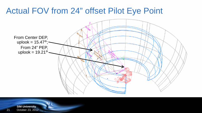
Actual FOV from 24” offset Pilot Eye Point
SIM UniversityOctober 23, 201221
From Center DEP, uplook = 15.47°;
From 24” PEP, uplook = 19.21°

Thank you.Questions?
SIM University 2012