
Silicon Auditory Processors as Computer Peripherals
8
Silicon Auditory Processors as Computer Peripherals .T ollll Lmr,7.Hl'o . .T ollll Wawl'7.Ylwk CS Division UC Evans lIall Bcrl,plpy. Ct\ !H720 M. Mahowald'" Massimo Sivilotti t , Dave Gillcspic t Califol'lIia lnst,itult' of Technology Pasadena. CA !) 11:l!) Abstract Sever<tl resE'<lI'ch gl'Oups cue impl('lllt'lIt.ing allalog integrat.ed circuit. models of hiological audit.ory Pl"Occ'ssing. The outputs of these circuit models takell sevel'al forms. includillg video [ormat. for monitor display, simple scanned Ollt.put [01' oscilloscope display anJ parallel analog out.put.s suitable ror dat.a-acquisition systems. In this pa.per, we describe an allel"llative out.put method for silicon auditory models, suit.able for din- 'ct. interface to digital computers. * Present address: f\1. Mahowald, f\1H.C ,\natol1lical Ncmophamacology Unit, Mansfield TId, Oxfc)('d OXI :1'rl£ Ellgland . t Present address: f\lass Siviloui. '1'(1111)(,1' H, csearrh, 180 Nort.h Vinedo Avenue, Pasadena, CA 9Il07. corn :I: Present address: Dave Gill,>spiE', SYllapf,ics, :l()!)8 Orchard Parkway, San Jose CA, 95131. com 820
Transcript of Silicon Auditory Processors as Computer Peripherals
Silicon Auditory Processors
as
Computer Peripherals
.T ollll Lmr,7.Hl'o . .T ollll Wawl'7.Ylwk CS Division UC B(~rk('ley Evans lIall
Bcrl,plpy. Ct\ !H720 lazzaro~cs.berkeley.edu, johnw~cs.berkeley.edu
M. Mahowald'" ~ Massimo Sivilottit , Dave Gillcspic t
Califol'lIia lnst,itult' of Technology Pasadena. CA !) 11:l!)
Abstract
Sever<tl resE'<lI'ch gl'Oups cue impl('lllt'lIt.ing allalog integrat.ed circuit. models of hiological audit.ory Pl"Occ'ssing. The outputs of these circuit models haV(~ takell sevel'al forms. includillg video [ormat. for monitor display, simple scanned Ollt.put [01' oscilloscope display anJ parallel analog out.put.s suitable ror dat.a-acquisition systems. In this pa.per, we describe an allel"llative out.put method for silicon auditory models, suit.able for din-'ct. interface to digital computers.
* Present address: f\1. Mahowald, f\1H.C ,\natol1lical Ncmophamacology Unit, Mansfield TId, Oxfc)('d OXI :1'rl£ Ellgland . mam~vax.oxford.ac.uk t Present address: f\lass Siviloui. '1'(1111)(,1' H,csearrh, 180 Nort.h Vinedo
Avenue, Pasadena, CA 9Il07. mass~tanner. corn :I: Present address: Dave Gill,>spiE', SYllapf,ics, :l()!)8 Orchard Parkway, San
Jose CA, 95131. daveg~synaptics. com
820
Silicon Auditory Processors as Computer Peripherals 821
1. INTRODUCTION
Several researchers have implemented comput.at.ional models of biological audit.ory processing, with the goal of incorporat.ing t.hese models into a speech recognition system (for a recent review, see (Jankowski, 1992)). These projects have shown the promise of the biological approach, someti Illes showing clear performance advantages over traditiona.l methods.
The application of t.IH'se comput.('tional models is limited by t.heir large computation and communication I·eqllil·ement.::.;. A lIalog VLSI implementations of these neural models may relieve t.his cOlllput.at.ional burden; several VLSI research groups have effort.s in this area, and working int.egrated circuit models of nlany popular representat.ions present.ly exist .. A review of t.h('se models is present.ed in (Lazzaro, 1991). In this paper, we present. an interface met.hod (Ma.howald, 1992; Sivilott.i, 1991) that addresses the cOll1l1lllnicHt.ions issues between analog VLSI auditory implementations and digital processors.
2. COMMUNICATIONS IN NEURAL SYSTEMS
Biological neurons COlli IllU lIicat.e 10llg dist.anc('s using a pulse represent.ation. Communications engineers have developed several schemes for communicat.ing on a wire using pulses as aLomic unit.s. In t.hese schemes, maximally using the communications bandwidth of a wire implies t.lw nlPan rat.e of pulses on t.he wire is a significant fract.ion of the maxil1lum pulse I'at.e allowed 011 the wire.
Using this criterion, nemal syst.el\1s lise wir('s very illefficiently. Tn most. parts of the brain, most. of the wires arc esselltia.lly inactive 1Il0st of the time. If neural syst.ems are not organized t.o fully ut.ilii':E' t.lw available handwidt.h of each wire. what does neural communica.tioll opt.illli;!'c'? 8\'idclI(,(' sllggest.s that. f'llcrgy consel·vat.ion is an important isslle for neural syst.f'lI1s. A silnpl(' st rat.egy fOl' enel'gy conservat.ion is t.he reduction of t.he t.ot.al Ill11I1I)('1' of \>lIls('s ill t.he representat.ioll. ivlany possible coding st.rategies sat.isfy t.his elwrgy rC'qllil'('lIwnt..
The strat.egies observed ill lI(,lIl'al SYSt.('IIIS share anot her ('0111111011 propert.y. Neural systems oftE'1I implenwnt. H class of COIIlPlltilt.ions ill a. Il\allller t.ha.t. produces an energy-efficient. out.put. encoding as all addit.ional bypl'Oduct .. The energy-efficient coding is not perfOl'tnE'd simply for comll1unica.t.ioll and immediat.ely reversed upon receipt, but is an int.egral part. of t.h(' n('w r('IH'csent.at.ioll. In this way, energyefficient neural coding is int.rinsically diffnc'lIt. frolll engineering da.ta compression techniques.
Temporal adaptat.ion. lat.('J'al inhihition, alld spike' colTelat.ions arc examples of neural processing methods tlIH1. perform illtercst.illg cOlllput.at.ions while producing an energy-efficient. OUt.PIlt. code. Thcst> repr('sent.a(.ional principles are t.he founda.tion of t.he neural computation and cOllll11unicat.ioll method we advocat.e in this paper, In this method, t.he out.put. units of a chip are spiking llelll'On circuit.s that use energy-efficient coding IlIet.hods. To COll1lllllllicat.f' t.his code off a c\rip, we liSE' a dist.inctly non-biological apPl'o(1eh.
822 Lazzaro, Wawrzynek, Mahowald, Sivilotti, and Gillespie
3. THE EVENT-ADDRESS PROTOCOL
The unique characteristics of enel·gy-efficient. codes define the remaining off-chip communications problem. In the spiking nemon protocol, the height. and width of the spike carries no informat.ion; the neuron imparts new information only at the moment a spike begins. This moment occurs asynchronously; there is no global clock synchronizing the output units. One way of completely specifying the information in the output units is an event list., a tabulation of the precise time each output unit. begins a new spike. vVe can use this specification as a basis for an off-chip communicat.ions system, t.hat. sends an event.-list message off-chip at the moment. an output neuron begins a new spike. An eVl'nt.-list message includes the identificat.ion of the output unit., and the t.ime of firing . A pcrformance analysis of' this protocol can be found in (Lazzal'O et al., l!J92).
Note that an explicit timest.amp for each clIt.l·y in t.he cvent list is not necessary, if communication lat.ency betwcen t.he scnding chip and the receiver is a constant. In this case, the sender simply com1l1I1nicRt,es, lIpon onset of a. spike from an output, the identit.y of the output. unit.; t.he l'eceivcl' can aPPclld a locally genera.ted timestamp to complete the event. If simplificd in t.his mallllcr, we refcl' to the event-list protocol as the event.-a.ddress protocol.
''''e have designed a \vol'king syst.em t.hat. comput.es a model of auditory nerve response, in rea] t.ime, usillg ana.log V LSI processing. This syst.em takes as input an analog sOllnd sOllrce. alld uses t.he eVPlIt.-list, I·('prl'sent.a.t.ion t.o communicat.e t.he model out.put to the host. computel·.
Board Architecture CJ 0 1--------- D Chip Architecture 1 I \\ttt~ \\\\\ I I I r--
1 Spiking ArbIters 1 l3us DO Analog I
1 and I ~ Ou tPllt
-i Paralld Processing Olll
A,Sf1us cardU I En('odlll~ : I I Array ~,---'
IPC 1 Tim.>r
l
" ."~ 1_- _______ J aa aaaaaaaaaa aaa aa aaaaaaaaaa aao DOD aa aaaaaaaaao aa aa aaaaaaaaa aao aa a aa
Sound Input
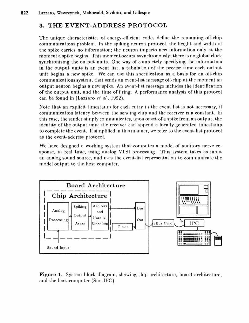
Figure 1. System block diagrnI1l. showing chip architecture, hoard a.rchit.ecture, a.nd the host. comput,(')' (SIlIl IPC).
Silicon Auditory Processors as Computer Peripherals 823
4. SYSTEMS IMPLEMENTATION
Figure 1 is a block diagl'am of this system. A single VLSI chip computes the auditory model response; an array of spiking neuron circuit.s is the final representation of the model. This chip also implements t.he event-address protocol, using asynchronous arbitration circuits. The chip produces a pa.rallel binary encoding of the model output, as an asynchronous stream of event addt·esses. These on-chip operations are shown inside the dashed recta.ngle in Figure 1, labelled Chip Architecture.
Additional digital processing com~letes t.he custom hardwa.re in the system. This hardware transforms the event.-address prot.ocol int.o an event-list. protocol, by adding a time marker for each event (16 bit time markers with 20ps resolution). In addition, the hardware implemellt.s the bus interface to the host computer, in conjunction with a commercial int.erface board. The commercial interface board supports 10 MBytes/second asynchronous da.ta tl'ansfers between our custom hardware and the host computer, and includes 8 KByt.es of data buffers. Our display software produces a real-time graphical display of the audit.ory model response, using the X window syst.em .
5. VLSI CIRCUIT DETAILS
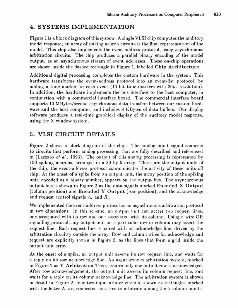
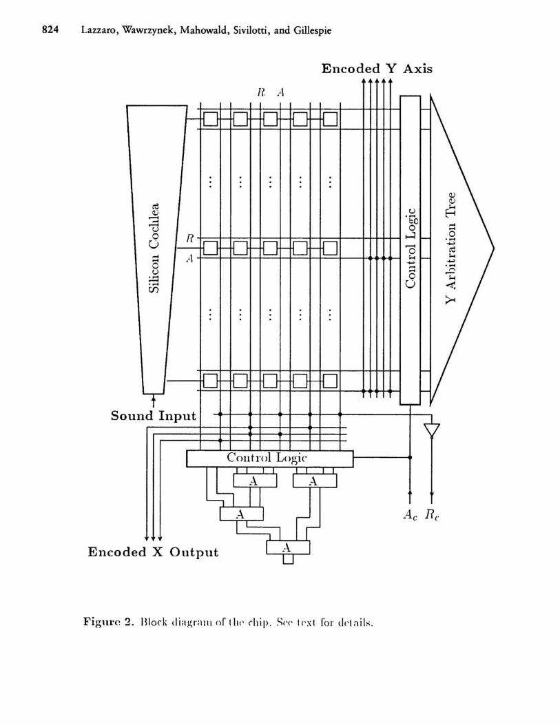
Figure 2 shows a block diagram of t.he chip. The analog input signal connects to circuits t.hat. perform analog pl'Ocessing, t hat are fully described and referenced in (Lazzal'O et al., 1993). The outpllt. of this analog processing is represented by 150 spiking neurons, arranged in a ~O by 5 array. These are the output units of the chip; the event.-address prot.ocol commllnicates t.he a.ctivity of these units off chip. At the onset of a spike from an output unit, t.he array position of the spiking unit, encoded as a binary number, appears on the output bus. The asynchronous out.put bus is shown in FigurE' 2 as t.he dat.a signals marked Encoded X Output (column position) and Encoded Y Output (row position), and the acknowledge and request control signals Ae and Re.
"Ve implemented the event.-address pl'Ot.ocol as an asynchl'Onous arbitration prot.ocol in two dimensions. ]ll t.his scheme, an out.put. unit. can access two request. lines, one a.<;socia.ted wit.h its row and one ;.)ssociat.ed with its column. Using a wire-OR signalling prot.ocol. any out.put. unit 011 a part.icular row or colllmn may assert the request line. Each request. lillE' is paired wit.h an acknowledge line, driven by the arbitration circuitt·y out.sidr. t.h0 array. Rowand column wires for acknowledge and request are explicit.ly showl! in Figll\'e 2. as t he lines that form a grid inside the output. unit. array.
At the onset of a. spike, an out.put. unit. a~sert .s it.s row request. line, and wait.s for a reply on it.s \'Ow acknowlf>dge line. An aSYllchronous arbit.rat.ion syst.em, mar'ked in Figure 2 as Y Arhitration Tree. aSSl\res only one out.put row is acknowledged. Aft.er row acknowledgement., the output unit. assel't.s its column request line, and waits for a reply on it.s COlU11111 acknowledge line. The al·bit.ration system is shown in detail in Figure 2: fOllr two-input. arhit.f'r circuit.s, shown a.<; rectangles marked with the letter A, arc connect.ed as a t.ree t.o arhit.rat.e among t.he 5 column inputs.
824 Lazzaro, Wawrzynek, Mahowald, Sivilotti, and Gillespie
Encoded Y Axis
n A r--
0 0 0 0 0 ~
I-- r- r- - ~
f-
· · . · · · · · . · Q,)
cd Q,) .....
v u H .-< ..... ..... bO
= .-< a u 0 R t-=l f-
a ..... U 0 0 0 0 0 --r- ~ r- r- .-< cd 0 ..... A ..... r- ..... ~ ~ --0 ..... ..... u .... f"'>
;.::: a ~ ..... U ~ U')
~ · · . · · · · · . ·
f-
0 0 0 0 0 l- f- t- t-
r-...... r-
So und Input V
I Control Loo'ic l") J
I A I I A- J
~ A- I II Ae Rc l
ed X Output l A U
Encod
Figure 2. Block dia p; ralll or t Itt' chip , S('( ' t('xt 1'0J'ddail:-; ,

Silicon Auditory Processors as Computer Peripherals 825
To Array n
--..---H------t--- Ac (b) ----+--------+--+---- At
A B
l?y
,..,' (C)
Ay
/.'
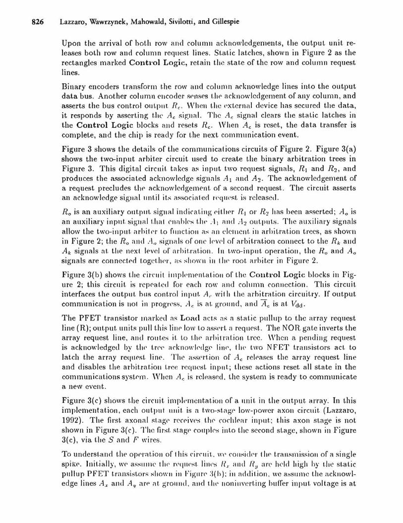
Figure 3. Diagrams of COllllllllllicatinn circllil:-; ill 1.1.(' citip. (a) Two-inpllt. arhit.er
circuit.. (b) ('olltl'ol lo~ic to illt(·rl'a('(· arhil 1';,1 iOIl logic alld Olltpill. IInit array. (c) Ollt.put. Illlit. ('ircllit..
826 Lazzaro, Wawrzynek, Mahowald, Sivilotti, and Gillespie
Upon the an'ival of hot.h row and column acknowledgement.s, t.he output unit releases both row and column request. lines. St.a.t.ic lat.ches, shown in Figure 2 as the rectangles marked Control Logic:, ret.ain t.he stat.e of the row and column request lines.
Binary encoders transfonl1 t.he row and column acknowledge lines int.o the output data bus. Another column encoder Sf'nses t.he acknowledgement of any column, and asserts the bus cont.rol OUt.PIlt. Re. \,"hell t.he ('xtcl'ncd device has secmed t.he data, it responds by a.'3sert.ing t.he Ae signal. The At: signal clears the st.at.ic latches in the Control Logic blocks and reset.s Re. When Ae is reset, the data transfer is complet.e, and the chip is reacly for t.he next communication event.
Figure 3 shows the deta.ils of the communications circuit.s of Figure 2. Figure 3(a) shows the t.wo-input cHhit.er circuit used to create t.he binary arbitration trees in Figure 3. This digital circuit. t"kcs a~ inpllt t.wo request signals, RI and R2 , and produces the a<;sociated acknowledge sigll:1ls Al and A2 • The acknowledgement of a request precludes the acknowledgement. of a second request. The cil·cuit. assert.s an acknowledge signal unt.il it.s clssocialed r'('qll!'st. is released.
Ro is an auxiliary out.put. sigllal indicat.ing eit.her HI 01' R",1 has been asserted; Ao is an auxiliary input. sigllal t.ltal enahl('s t.ht' .. \ I rllld +~ out.put.s. Tlte auxiliary signals allow the two-input. 'Hhit<'r· t.o fllnctioll as an elcrllcnt. ill arhit.rat.ion trees, as shown in Figure 2; the Ro and AI) sip;nals of one I('vel of arbit.ra.t.ion cOllnect to the Rk and Ak signals at. t.he next level of cuhit.rat.ion. rn !.\Vo-input. operat.ioll, t.he Ro and Ao signals are connect.NI t.ogct.lwl', as sbon-II ill I he' root. arhit.er in Figure 2.
Figure 3(b) shows t.lre circuit illlpl('lllellt.at.ioll of t.he Control Logic blocks ill Figure 2; this circuit is rcpC'at.cd for ea.ch row and col1lmn connect.ion. This circuit. interfaces t.he output. hilS cont.rol input. Ac wit II t.he c\l·hitrat.ion cil·cuitl'Y. If output. communicat.ion is not in progr('ss, Ac is at, ground, and Ac is at. \idd.
The PFET transist.or marked a~ Load act.s as a st.at.ic pullllp to t.he array request line (R); out.put unit.s pull t.his lillt" low t.o as:'o:<Tt ,1 request.. The NOR gat.e invert.s the array request line, alld rout.es it. t.o (.\W arhitration t.ree. When a penuillg request is ackno",.ledged by tIl<' I.r<'<' ackllo\\'I(' dge linC', till' two NFET t.ransist.ors act. t.o latch the army request. lilw . The ass<'ltion of .... le releases t.he array request line and disa.bles t.he arhit.rat.ioll LI·ce request. inpllt.; t.hese actions reset all st.ate in the communicat.ions syste'm . '''llCn AI; is releas(~d, the syst.em is ready t.o communicate a. new event.
Figure 3(c) shows t.he circuit. implernclltat.ion of a Hnit. in the output aITay. In t.his implcmentat.ion, each out.put ullit. is a t.wo-st.age lo\\,-powel· axon circuit. (Lazzaro, 1992). The first. axonal st.ag(' r('ceiV<'s t.he' cochlear input.; t.his axon st.age is not shown in Figure 3( c). The fil·sf. st.agf' couple'S illt.o the second st.age, shown in Figure 3(c), via t.he Sand F wires.
To underst.and t.ht' opt'rat.ioll of' this circll it.. WI' C01ISid('r t I If' t.rallsrnis~ioll of a single spil-\t'. Init.ially, We' a~Sllllle the n'<jll('st. lilh's I?,. and ay are held high hy t.lte st.at.ic pl\lIup PFET t.ransist.ors shown ill Figlll·(' :J(h); ill addit.ion, we aSSIJIlle the a.cknowledge lines A.r and A" arp at. gWlllld, alld tilt' 1I0nillvert.ing hurrer input. voltage is at
Silicon Auditory Processors as Computer Peripherals 827
ground.
When the first. axonal st.age fires, the S signal changes from ground potential to Vdd. At this point the buffer input voJt.agf! begills t.o increase, at a rate determined by the analog cont.I·ol voltage P. Whcn t.he swit.ching threshold of t.he buffer is reached, the buffet output. volt.ag(' F swings \,0 \/dd ; capacit.ive feedback ensures a reliable switching transitioll. At this point, the output, unit. Plllls the request line Ry low, and the cOnllllllnirat.ions sequellre hegins .
The Y arbitl'ation logic I'('plies 1.0 t 11<' Ry rf'qu('st. by asserting t.he Ay line. 'Vhen both F and Ay are asscJ'tcd, t.hc output ullit. pulls the reqllest. line R.r: low. The X arbitration logic replies to t.he R.r: I'equcst hy asserting t.he Ax line. The assertion of both Ax aBd Ay reset,s t.IH~ burrel' input voltagc t.o gl"Ound. As a result, the F line swings to ground potent.i<ll, t.hc out.put. unit. releases thc Rx a.nd Ry lines, and the first axon stage is enahled. At. t.his point., the l<lt.ch cil'cuit. of Figme 3(b) maintains the state of the Rx and 17,/ lines, IInt,il it is cleared by the off-chip acknowledge sign a. I.
Acknowledgements
Research and prot.ot.ypillg of t.he ('vc-nt-addr('ss illt('rface took place in Carver J\Jead's laborat.ory at. Calt,('('il: we arc' grateful for his illsights, CrtrOllragell1ellt., and support.. The Caltech-hased 1'('s<"Hrdl was funded by t.1t(' ONH, UP, and t.he Syst.ems Development. Foundat.ion. HCS('aJ'ch and prot,otyping of I.he allditory-nerve demollstrat.ion chip and syst.em took place a1 (1(' n(,l'kd(~y, alld was flll1(kd by t.he NSF (PYI award l\lIPS-895-8568), AT,,:T, al\d t.he ONH (UHI-l'\OOOl/1-02-.J-1672).
Rcfel'cuees
Jankowski. C. R. (1 m.l:2). "1\ ('olllparisoll of ,\ IIdit.ory l'\'lodcls for A lItomat.ir Speech Recognit.ion," S.13. TI1('~i:-;, ;\[1'1' Ikpt. of Electrical Ellgillc<.'\'ing and Comput.cl' Science.
Lazz;uo, J . P. (IH!H). "Biologically-h(ls('d auditory signal pl'ocessing in analog V LSI," IEEE A.'iilo/lla1' ('ollje 1'( lin 011 Sl[jll(ll.~ . . '3ys/c1Il.'i. (/.lId Comp1liers.
La7,zaro, J. P. (199:2). "l,o\\,-po\\,('J' ~ilicoll spiking I}(,\lron~ and :nons," IEEE 11Iterualiol/al S'ympo,<;iu1ll 01/ CiJ'CIt".~ (l1Id ,'1'.1/,1;/(1/1.,. Sail Di('go, CA, p . 2:22U-:22:2-1.
Lazzaro, J., \\'awl'zYlWk, .1., ~Iaho\\'ald, ~I., Sivilot.f.i, ~L, and Gillespie, D. (1993). "Silicon audit.ory pro('(~ssorS as (,OlllplItcr peripIH'I'als," IEEE Trallsactiolls of Ne'IIT'a/ Nelworks. May (ill pr('ss).
Mahowald, 1\I. (1992). Ph.n. Thesis, COlllplltat.ion and NCll\'al Syst.ems, California. Instittlt.r of Technology.
Sivilot.t.i, 1\1. (1991), "Wirillg ('ollsi(krat.iolls ill analog VLSr syst.ems, wit.h applicat.iolls to fh'ld-progrnllll1lahlc' 11('\ works," (:0111 pllt.('r Sciel1r(' Technical Heport. (Ph. D. Thesis), Califol'llia 11lSit.II1.<' of'T('cllllology,