Silent Messenger IV Vehicle Mounted Procurement...
21
Silent Messenger Solar Powered Portable Changeable Vehicle Mounted Message Boards Procurement Specifications ® Harness the Power of the Sun 7620 Cetronia Road, Allentown, PA 18106 n Phone 610-391-8600 www.solartechnology.com Harness the Power of the Sun! for MB IV Message Boards
Transcript of Silent Messenger IV Vehicle Mounted Procurement...

Silent MessengerSolar Powered Portable Changeable
Vehicle MountedMessage Boards
Procurement Specifications
®
Harness the Power of the Sun
7620 Cetronia Road, Allentown, PA 18106 n Phone 610-391-8600 www.solartechnology.com
Harness the Power of the Sun!
for MB IV Message Boards
Silent Messenger III Vehicle Mount Procurement Specifications Cover REV-C.pmd 09/01/2009
Copyright © 2003 Solar Technology, Inc. All rights reserved.
SolarTech, SILENT MESSENGER SOL-R-SIGN, and Command Center are trademarks of Solar Technology, Inc.
Microsoft, Windows 95, Windows 98, Windows NT, Windows 2000, Windows XP, Windows Vista, Windows 7 andother Microsoft products referenced herein are registered trademarks of Microsoft Corporation.
All other brands and product names mentioned herein are used for identification purposes only, and are trademarksor registered trademarks of their respective holders.
This document presents a detailed specification for a small-size vehicle-mounted Dynamic (Changeable)Message Sign. This specification typically requires additions and/or modifications to meet a user'sspecific requirements.
This specification is subject to periodic revisions as required without notice.
Twelfth Edition: 25 August 2016
General email: [email protected] Support email: [email protected]
Web site: www.solartechnology.com
SILENT MESSENGER IV Page 1 of 19
Silent Messenger III Vehicle Mount Procurement Specifications REV-A.pmd 12/20/2007
SolarTech, Inc. Vehicle Mount Dynamic Message Sign Procurement Specification
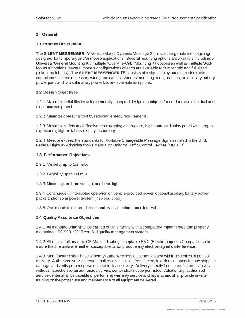
1. General
1.1 Product Description
The SILENT MESSENGER IV Vehicle Mount Dynamic Message Sign is a changeable message signdesigned for temporary and/or mobile applications. Several mounting options are available including: aUniversal/General Mounting Kit, multiple “Over-the-Cab” Mounting Kit options as well as multiple Skid-Mount Kit options (several models/configurations of each are available to fit most mid and full sizedpickup truck beds). The SILENT MESSENGER IV consists of a sign display panel, an electroniccontrol console and necessary wiring and cables. Various mounting configurations, an auxiliary batterypower pack and two solar array power kits are available as options.
1.2 Design Objectives
1.2.1 Maximize reliability by using generally accepted design techniques for outdoor-use electrical andelectronic equipment.
1.2.2 Minimize operating cost by reducing energy requirements.
1.2.3 Maximize safety and effectiveness by using a non-glare, high contrast display panel with long-lifeexpectancy, high-reliability display technology.
1.2.4 Meet or exceed the standards for Portable Changeable Message Signs as listed in the U. S.Federal Highway Administration’s Manual on Uniform Traffic Control Devices (MUTCD).
1.3 Performance Objectives
1.3.1 Visibility up to 1/2 mile.
1.3.2 Legibility up to 1/4 mile.
1.3.3 Minimal glare from sunlight and head lights.
1.3.4 Continuous uninterrupted operation on vehicle-provided power, optional auxiliary battery powerpacks and/or solar power system (if so equipped).
1.3.5 One month minimum, three month typical maintenance interval.
1.4 Quality Assurance Objectives
1.4.1 All manufacturing shall be carried out in a facility with a completely implemented and properlymaintained ISO 9001:2015 certified quality management system.
1.4.2 All units shall bear the CE Mark indicating acceptable EMC (Electromagnetic Compatibility) toinsure that the units are neither susceptible to nor produce any electromagnetic interference.
1.4.3 Manufacturer shall have a factory authorized service center located within 150 miles of point ofdelivery. Authorized service center shall receive all units from factory in order to inspect for any shippingdamage and verify proper operation prior to final delivery. Delivery directly from manufacturer’s facilitywithout inspection by an authorized service center shall not be permitted. Additionally, authorizedservice center shall be capable of performing warranty service and repairs, and shall provide on-sitetraining on the proper use and maintenance of all equipment delivered.
Vehicle Mount Dynamic Message Sign Procurement Specification SolarTech, Inc.
Page 2 of 19 SILENT MESSENGER IV
Silent Messenger III Vehicle Mount Procurement Specifications REV-A.pmd 12/20/2007
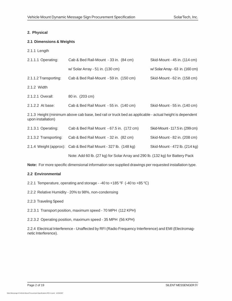
2. Physical
2.1 Dimensions & Weights
2.1.1 Length
2.1.1.1 Operating: Cab & Bed Rail-Mount - 33 in. (84 cm) Skid-Mount - 45 in. (114 cm)
w/ Solar Array - 51 in. (130 cm) w/ Solar Array - 63 in. (160 cm)
2.1.1.2 Transporting: Cab & Bed Rail-Mount - 59 in. (150 cm) Skid-Mount - 62 in. (158 cm)
2.1.2 Width
2.1.2.1 Overall: 80 in. (203 cm)
2.1.2.2 At base: Cab & Bed Rail Mount - 55 in. (140 cm) Skid-Mount - 55 in. (140 cm)
2.1.3 Height (minimum above cab base, bed rail or truck bed as applicable - actual height is dependentupon installation)
2.1.3.1 Operating: Cab & Bed Rail Mount - 67.5 in. (172 cm) Skid-Mount - 117.5 in. (299 cm)
2.1.3.2 Transporting: Cab & Bed Rail Mount - 32 in. (82 cm) Skid-Mount - 82 in. (208 cm)
2.1.4 Weight (approx): Cab & Bed Rail Mount - 327 lb. (148 kg) Skid-Mount - 472 lb. (214 kg)
Note: Add 60 lb. (27 kg) for Solar Array and 290 lb. (132 kg) for Battery Pack
Note: For more specific dimensional information see supplied drawings per requested installation type.
2.2 Environmental
2.2.1 Temperature, operating and storage - -40 to +185 0F (-40 to +85 0C)
2.2.2 Relative Humidity - 20% to 98%, non-condensing
2.2.3 Traveling Speed
2.2.3.1 Transport position, maximum speed - 70 MPH (112 KPH)
2.2.3.2 Operating position, maximum speed - 35 MPH (56 KPH)
2.2.4 Electrical Interference - Unaffected by RFI (Radio Frequency Interference) and EMI (Electromag-netic Interference).
SILENT MESSENGER IV Page 3 of 19
Silent Messenger III Vehicle Mount Procurement Specifications REV-A.pmd 12/20/2007
SolarTech, Inc. Vehicle Mount Dynamic Message Sign Procurement Specification
3. Frame and Sign Support
3.1 Frame Construction
3.1.1 Mounting frames shall be constructed from a combination of welded 7 Gauge (3/16-inch) and 1/4inch CNC formed steel plate, 2 x 4 x 1/8 inch structural steel tubing, 2 x 2 x 3/16 and 2 x 2 x 1/8 inchstructural steel tubing and 2 x 2 x 1/8 HRS angle as appropriate per specific application.
3.1.2 Skid-mount frame base shall accommodate the addition of an enclosure for the optional batterypower pack.
3.1.3 All frames shall be designed such that the sign panel and any optional equipment mounteddirectly to the frames facilitate quick, easy installation and removal from vehicle.
3.1.4 All frames shall be equipped with tie down points and/or foot pads with mounting holes to facilitatesecuring to vehicle.
3.1.5 All frames shall be completely assembled with removable fasteners to accommodate quick, easymaintenance and repair.
3.1.6 All fasteners shall be rust resistant and equipped with all metal (stover) or nylon-stop lock nuts toprevent loosening of fasteners during normal transportation and operation.
3.2 Sign Panel Support
3.2.1 Sign panel mounting/support arms shall be constructed from 2 x 2 x 1\4-inch HRS angle.
3.2.2 Pivoting sign panel support frame shall accommodate the addition of an optional integratedsupport frame for mounting the optional solar array. The solar array shall be positioned to accommodatecharging in both the operating and the traveling positions.
3.2.4 Pivoting sign panel support shall be designed such that it may be equipped with either a manu-ally-operated automatic-brake winch and cable mechanism (skid mount option only) or a 12VDC motor-operated remotely-controlled linear actuator for raising & lowering the sign panel and optional solararray, if so equipped, from the travel position into the operating position.
3.2.5 All aluminum to steel attachments shall be made with stainless steel hardware and stainlesssteel or nylon spacers so as to minimize galvanic corrosion.
3.3 Sign Panel Lifting Mechanism
3.3.1 Manual Winch and Cable Mechanism - Manual Winch (Skid-Mount Option Only)
3.3.1.1 Sign panel lifting mechanism shall consist of a minimum 1,000-pound capacity, automaticbrake type winch with 1/4-inch wire rope capable of holding the arrow panel in any position from fullupright to the travel (down) position.
3.3.1.2 Winch shall be zinc-plated to minimize rust and corrosion.
3.3.1.3 Winch shall be designed such that the handle can be removed, for added security, withoutinterfering with the operation of the automatic brake.
3.3.1.4 Sign panel shall be secured in the operating (up) position by two stainless steel, spring-loaded,locking pins.
Vehicle Mount Dynamic Message Sign Procurement Specification SolarTech, Inc.
Page 4 of 19 SILENT MESSENGER IV
Silent Messenger III Vehicle Mount Procurement Specifications REV-A.pmd 12/20/2007
3.3.2 Remote-Controlled Motor-Operated Linear Actuator - Power Lift Option (All Pivoting Mount Installations)
3.3.2.1 Linear actuator shall be a completely sealed (weatherproof) lead-screw and ball bearing typedrive system with integrated force limiting clutch mechanism to prevent mechanical damage to unit inevent of mechanical failure/interference of pivoting mechanism.
3.3.2.2 Linear actuator shall provide a minimum operating force of 1,000 lb. (4,448 N) and a minimumholding force of 3,000 lb. (13,333 N).
3.3.2.3 Linear actuator shall be equipped with a bidirectional brake to hold the sign panel in anyposition along with electronic end of stroke (Hall-Effect) limit switches to prevent over travel in eitherdirection.
3.3.2.4 Linear actuator shall operate from a nominal 12 Volt DC power source.
3.3.2.5 Linear actuator shall be capable of completely raising or lowering the sign panel in less than 25seconds.
3.3.2.6 The linear actuator control unit shall be equipped with LED indication to denote when the signpanel is in the fully raised, intermediate and fully lowered positions.
3.4 Surface Preparation and Finishing
3.4.1 Frame structure shall be completely cleaned and deburred prior to finishing. All metal surfacesshall be prepared for finishing using an iron phosphate wash-down process.
3.4.2 A polyamide epoxy primer shall be applied to a dry film thickness of 1.5 mils.
3.4.3 A matte black aliphatic acrylic urethane finish shall be applied to a dry film thickness of 1.25 mils.
4. Message Display Panel
4.1 Dimensions
4.1.1 Width Overall - 60 in. (152 cm)
4.1.2 Height Overall - 30 in. (76 cm)
4.1.3 Depth Overall - 6 in. (15 cm)
4.2 Construction
4.2.1 Message Display Panel Case
4.2.1.1 The message display panel case shall be constructed of heavy duty aluminum extrusionsecured at each corner by a molded, fiberglass-reinforced plastic corner and black powered coatedstainless steel torx head screws and nylon insert locknuts.
4.2.1.2 The back of the message display panel case shall be constructed of aluminum sheet bondedand riveted to the case frame.
4.2.1.3 Interior of message display panel case shall be equipped with extruded aluminum channels toreinforce the display case and to support internal wiring and cables.
SILENT MESSENGER IV Page 5 of 19
Silent Messenger III Vehicle Mount Procurement Specifications REV-A.pmd 12/20/2007
SolarTech, Inc. Vehicle Mount Dynamic Message Sign Procurement Specification
4.2.1.4 The display panel case shall be equipped with four breather filter vents, designed to allow theflow of vapor but not fluid, located at the top and bottom of the case frame to provide adequate ventilationto minimize condensation and fogging of the display panel door.
4.2.2 Message Display Panel Door
4.2.2.1 The display panel door shall be constructed of heavy duty extruded aluminum secured at thecorners with glass fiber reinforced molded plastic inserts and black powered coated stainless steel torxhead screws and nuts.
4.2.2.2 The door shall fit within a flange around the perimeter of the message display panel case frameto provide for a secure weatherproof enclosure.
4.2.2.3 A rubber seal shall be located inside of the flange on the case frame to provide a water tight,dust tight closure.
4.2.2.4 The message display panel shall be enclosed over the display area by a 3/16-inch thick clearUV resistant, scratch resistant, acrylic coated polycarbonate material with a non-glare outer surface toreduce reflection of ambient light and oncoming vehicle head lamps.
4.2.2.5 The polycarbonate material shall be secured in the door frame with an extruded rubber u-channel to provide a cushioned, weatherproof seal.
4.2.2.6 The message display panel door shall be secured in the open position for servicing by a pair ofzinc-plated steel telescoping lid supports equipped with automatic latches. The door supports shall belocated completely inside of the display panel housing, protected from weather.
4.2.2.7 The display panel door shall be secured in the closed position with adjustable, positive locking,stainless steel draw latches.
4.2.2.8 The message display panel door and case shall be equipped with stainless steel locking haspscapable of accepting standard padlocks to secure the door in the closed position.
4.2.3 Surface Preparation and Finishing
4.2.3.1 Message display panel case and door shall be completely cleaned and deburred prior tofinishing. All metal surfaces shall be prepared for finishing using an iron phosphate wash-down process.
4.2.3.2 A wash primer shall be applied to all prepared metal surfaces prior to applying final finish.
4.2.3.3 A matte black acrylic urethane finish shall be applied to a dry film thickness of 2.5 mils.
4.3 Display Characteristics
4.3.1 The message display area shall be approximately 54 inches in width by 24 inches in height.
4.3.2 The display area shall consist of a continuous (full) matrix of either (specify): 36 pixels in width by16 pixels in height for a 38mm pixel pitch display -or - 72 pixels in width by 32 pixels in height for a19mm pixel pitch display.
4.3.3 The pixels shall consist of either two (2) LEDs (Light Emitting Diodes) arranged in a close-spacedpattern so as to produce the appearance of a round image or dot at normal viewing distances for a 38mmpixel pitch display - or - a single LED in the case of a 19mm pixel pitch display.
Vehicle Mount Dynamic Message Sign Procurement Specification SolarTech, Inc.
Page 6 of 19 SILENT MESSENGER IV
Silent Messenger III Vehicle Mount Procurement Specifications REV-A.pmd 12/20/2007
4.3.4 The display color shall be amber (592 nanometer wavelength).
4.3.5 The display shall produce a brightness greater than 10,000 candela per square meter at maxi-mum intensity.
4.3.6 The display shall produce a minimum viewing angle of 24 degrees, with consistent intensity andcolor across the entire display panel.
4.3.7 The message display panel shall be capable of displaying multiple lines of alphanumeric charac-ters or text with a nominal character height ranging from a minimum of 7.5 inches (19 cm) to a maxi-mum of 21 inches (53 cm) for a 38mm pixel pitch display - or - 3.75 inches (9.5 cm) to a maximum of19.5 inches (49.4 cm) for a 19mm pixel pitch display.
4.3.8 The message display panel shall be capable of displaying at least two lines of text with a mini-mum of three pixels between lines.
4.3.9 The message display panel shall also be capable of displaying graphic images and symbols usingthe full 32 / 72 pixel width and 16 / 32 pixel height array.
4.4 Display Modules
4.4.1 Display modules shall be mounted in the sign panel using captive 1/4-turn wing-head fasteners topermit quick, easy module replacement without the need for any tools.
4.4.2 Display modules shall be mounted on rubber cushions to provide shock absorption during trans-port and to accommodate thermally-induced expansion and contraction of message display panel duringoperation.
4.4.3 Display module control circuitry shall include a fail-safe device, also know as a watchdog timer, toautomatically monitor the performance of the display module and provide a reset / restart command tothe on-board microcontroller in the event of any disruption of normal operation.
4.4.4 Display module control circuitry shall be designed to accommodate “hot swapping” - exchange ofdisplay modules while sign is operating.
4.4.5 The message display shall consist of an array of identical display modules capable of functioningin any position without the need for switch or jumper setup or special programming.
4.4.6 Display modules and message display panel shall accommodate complete service and exchangeof display modules without the need for any tools.
4.4.7 Display modules shall be equipped with locking-type electrical / electronic connectors to providesecure, reliable operation while permitting quick, easy service and repair of message display.
4.5 Cables and Wiring
4.5.1 All message display panel wiring and cables shall be equipped with modular power and signalconnectors to permit repairs without the need for any tools.
4.5.2 All power circuit connectors shall use tin or silver plated contacts.
4.5.3 All signal circuit connectors shall use gold plated or gold flashed contacts.
4.5.4 All system wiring, power and signal, shall consist of marine grade wire and cable, with multi-strand, tin-plated conductors.
SILENT MESSENGER IV Page 7 of 19
Silent Messenger III Vehicle Mount Procurement Specifications REV-A.pmd 12/20/2007
SolarTech, Inc. Vehicle Mount Dynamic Message Sign Procurement Specification
4.5.5 All power and sign panel signal wiring and cables shall be installed in nonmetallic, flexible, liquid-tight conduits. All conduit fittings shall be installed with rubber sealing rings to maintain liquid-tightcharacteristics.
5. Main Control Console
5.1 Physical
5.1.1 Control console shall be enclosed in a weather resistant, lockable, molded HDPE (High DensityPolyethylene) enclosure secured to the trailer chassis.
5.1.2 Control console shall be completely sealed to accommodate operation in all types of weather.
5.1.3 Control console shall be mounted on heavy duty slides which allow the control console to slide upand pivot into a position enabling the operator to program the unit while facing traffic from a comfortablestanding position. A controller location which requires the operator to stoop, bend or kneel for operationsuch that the operator cannot see approaching traffic shall not be permitted. Slide mechanism shallpermit quick, easy removal of control console without the need for any tools.
5.1.4 Control console power and control cables shall include sealed, locking-type connectors to permitquick, easy removal of control console without the need for any tools.
5.1.5 Control console front panel shall consist of a backlit full color LCD (liquid Crystal Display) withintegrated industrial grade touch-screen, sealed and waterproof, to provide a reliable and user-friendlyinterface for the operator under any weather condition.
5.2 General Operation
5.2.1 Control console shall provide for full local and remote (via integrated cellular transciever andantenna) control of the dynamic message sign including dynamic message sign geographic locationmonitoring (via integrated GPS module and antenna), radar speed monitoring and statistical datacollection (when equipped with optional radar speed monitor) and sign panel orientation monitoring(when equipped with optional digital flux-gate compass), without the need for additional hardware,software, external computers or hand-held control devices.
5.2.2 Control console shall include all necessary hardware and software to operate the dynamicmessage sign locally (via integrated full color LCD display and touch-screen) and remotely (via inte-grated cellular transciever and antenna), including geographic location monitoring (via integrated GPSmodule and antenna), radar speed monitoring and statistical data collection (when equipped withoptional radar speed monitor), and sign panel orientation monitoring (when equipped with optional digitalflux-gate compass). Full remote control (including GPS mapping) via internet accessable server basedremote control software shall be included free of charge for life of the unit (i.e. cellular service shall beincluded free from date of original purchase).
5.2.3 Control console, in conjunction with the message display panel, shall have the capability ofmonitoring and detecting sign panel communication loop failures. In the event of a sign panel communi-cation loop failure, the control console, in the case of soft errors (temporary disruption of messagedisplay), shall have the ability to correct the failure immediately and in the case of hard errors (hardwarefailure), shall have the ability to completely blank the sign panel so as to prevent the display of incorrectand/or potentially misleading messages. Additionally, control console, in conjunction with the messagedisplay panel, shall have the capability of continuously and dynamically (as well as on command)testing and reporting the operational status of each and every individual pixel in the sign panel. Non-operational pixels shall be indicated as such on both local and remote user interfaces. Control console
Vehicle Mount Dynamic Message Sign Procurement Specification SolarTech, Inc.
Page 8 of 19 SILENT MESSENGER IV
Silent Messenger III Vehicle Mount Procurement Specifications REV-A.pmd 12/20/2007
shall have the capability of reporting complete sign panel operational status remotely (including web-access, NTCIP, and UTMC). Additionally, control console shall have multiple diagnostic modes (manual& automatic with both local and remote controls) for troubleshooting sign panel (including a graphicalrepresentation of all modules with non-operational pixels) to enable an operator to quickly track downand replace faulty display modules in the sign panel.
5.2.4 Control console embedded CPU shall incorporate an ARM based microprocessor design to insurefuture hardware and software compatibility through upgrades provided by manufacturer free for life of themachine. Operating system shall be Linux based and include multiple watchdog timers to ensureautomatic system restarts in the event that any critical function stops working properly or communica-tion with remote control servers is interrupted.
5.2.5 Control console shall be capable of connection to any standard IBM or compatible desktop orportable (lap-top) computer via a standard serial interface (COM) or Ethernet port to facilitate routineservice or repair, extensive diagnostics, and the analysis of user files or operating programs.
5.2.6 Control console shall be equipped with at least one USB port, one Ethernet port, two (2) serialports (DB-9 connector), two (2) digital outputs, six (6) digital inputs, and two (2) analog inputs.
5.2.7 Control console shall be capable of simultaneously driving more than one sign panel for dualsign panel installations.
5.2.8 Control console operating processor, firmware and software shall be field (locally) upgradeablewith a standard USB flash-drive (memory key) or remotely upgradeable over an IP addressable networkconnection - wire-line or wireless via IP addressable modem. Additionally, upgrades shall be provided bymanufacturer free of charge for life of machine and automatically applied via integrated cellulartransciever and included remote control service.
5.2.9 Full color LCD display shall be equipped with an automatic backlight with automatic dimmingcapability to accommodate both direct sunlight daytime and low ambient light level night time opera-tion. Backlighting shall automatically activate upon any touch-screen activity and remain on for fiveminutes following the last touch-screen activity. Additionally, an automatic log-out feature shall beincorporated to insure security of the unit when left unattended. Automatic log-out feature shall becapable of being disabled by the operator as desired (i.e. for vehicle mounted applications).
5.2.10 Main power to the sign panel and the control console shall be controlled by a combinationswitch and circuit breaker in order to provide electrical protection without the need for fuses. All connec-tions to controller and Energy Management System shall be made with locking type quick disconnectconnectors. The use of fuses and/or terminal strips for connections shall be strictly forbidden.
5.3 Programming
5.3.1 Control console shall provide an intuitive icon-driven graphical user interface (GUI) along with stepby step instructions to the operator, via the LCD display, as the various programming functions areperformed, for simple easy programming and operation. On-screen help files shall be included in alllanguages. Control console shall support a minimum of six (6) standard operating languages (English,Spanish, French, Dutch, German and Portuguese) and four (4) standard keyboards (English, French,Portuguese/Spanish, and Arabic) along with associated font sets. Controller shall be capable of beingsetup for either a Standard US DOT, Power-Miser US DOT, Standard US 3-Line DOT, French Canadian,Ontario MTO-2, Quebec Road Safety, MTQ, or an International font set by an operator with Administratoraccess to prevent unauthorized use of inappropriate fonts by operators with User access.
SILENT MESSENGER IV Page 9 of 19
Silent Messenger III Vehicle Mount Procurement Specifications REV-A.pmd 12/20/2007
SolarTech, Inc. Vehicle Mount Dynamic Message Sign Procurement Specification
5.3.2 Control console shall be capable of storing all messages in alphabetical order by the first letter ofthe first word of the name assigned to the message to permit quick recall of messages without the needfor maintaining a numeric listing of pages and/or messages. Messages shall be automatically namedand sorted any time messages are added to or deleted from the library. Because of difficulty in locatingand retrieving stored pages and/or messages via numerical codes, number coded storage of pages and/or messages requiring any form of a lookup table/directory shall be strictly forbidden.
5.3.3 Control console shall accommodate a minimum of fifty (50) full alphanumeric passwords eachproviding one of four levels of access to various control console functions. Each password shall allowaccess to only the functions required by that particular dynamic message sign operator. The four levelsof access are as follows:
Quick-Picks Select from up to six (6) pre-programmed messages with noprogramming required. Simply touch a message for display.No access to any permanent data files.
User Menu Create, Edit, Delete, Save, Display, and Schedule messages.Create, Assign and Edit Quick-Picks.Check System Status and perform basic diagnostics.
Supervisor Menu All User Menu Functions.Create and delete Quick-Picks and User passwords.Set system operating parameters.
Administrator Menu All Supervisor Functions.Create and delete Administrator and Supervisor passwords.Set controller operating parameters.
5.3.4 Control console shall be capable of displaying a message on the message sign display panelduring such time as the operator may be adding, editing or deleting messages from the control consoleuser files. Blanking of the message sign display panel during normal operator activity is consideredunsafe and shall be strictly forbidden.
5.3.5 Control console shall be capable of monitoring ambient light conditions and making appropriateadjustments to the intensity of the sign panel to maintain an acceptable display contrast during allambient lighting conditions. The control console shall provide a minimum of sixteen (16) intensity levelsbetween minimum and maximum display brightness. An operator with Supervisor access shall becapable of adjusting the upper and lower photocell set-points as to adjust the overall range for theautomatic brightness control to accommodate any local variations in ambient lighting. Manual control ofsign panel intensity shall be provided as well enabling an operator with Supervisor access to overrideautomatic sign panel intensity control and set sign panel intensity manually from 1% to 100% in 1%increments.
5.3.6 Control console shall be equipped with a Scheduler that utilizes a real time clock and calendarfeature to accommodate automatic, unattended changing of messages at predetermined dates andtimes. Scheduler shall support unique, single event schedules along with recurrent schedules such thatmessages may be easily scheduled for daily, weekly or monthly repetition. Recurrent schedules shallbe capable of incorporating a start and stop date as desired. Scheduler shall also be capable ofdisplaying messages based upon data driven events such as input from a radar gun, photocell, batteryvoltage, temperature and/or switch closures (up to six). Data driven events shall also be capable ofbeing restricted to specific dates and times. Scheduler shall incorporate a priority system for resolutionof conflicting schedules and/or events to permit one schedule/event to override another based upon
Vehicle Mount Dynamic Message Sign Procurement Specification SolarTech, Inc.
Page 10 of 19 SILENT MESSENGER IV
Silent Messenger III Vehicle Mount Procurement Specifications REV-A.pmd 12/20/2007
level of importance (i.e. priority). Additionally, the control console shall have the capability to createand display on the sign panel an Override Message that takes priority and overrides all programmedSchedules and Events until cleared to enable an operator to display a message continuously on thesign panel regardless of programmed schedules and/or events.
5.3.7 Control console shall provide special function buttons to provide access to common user func-tions in a single step including (from the main log-on screen) Managing Messages, Scheduling Mes-sages, Blanking the Sign Panel, creating an Instant Message, and selecting from Quick Picks.
5.3.8 Control console shall provide a system status page that enables an operator to quickly and easilydetermine the unit’s current time, date, photocell reading, photocell set-points, battery bank voltage,battery bank current, solar array voltage, solar array current, temperature, MAC address, IP address,run-time since last re-boot, current run-time (resettable timer), lifetime run-time, and serial modem typealong with modem signal strength and quality, latitude & longitude and sign panel heading.
5.3.9 Control console shall be capable of storing a minimum of 5,000 messages, each messagecapable of accommodating a minimum of 500 pages (text or graphic images).
5.3.10 Control console shall provide a minimum of twelve (12) font sizes (with full uni-code support foreach font) including an adaptive font that automatically and dynamically sizes text to fit on a page as itis typed such that the largest font is always used for a given amount of text on a page to ensuremaximum visibility and legibility. One of the included font sizes shall be a standard 5x7 DOT pixel font.
5.3.11 Control console shall support the incorporation of multiple dynamic data sources per page duringmessage creation such that multiple pages within a message can include output from multiple dynamicdata sources. Pages containing dynamic data sources shall be automatically refreshed and updatedprior to each display such that the most recent data is always displayed on the sign panel. Systemshall include, as a minimum, the following data sources: radar gun (if equipped), real-time clock (timeand date - day, month, year and time in various formats), photocell (ambient light level), battery voltage,and countdown & count-up features from a specified date and/or time. System shall also provideoperator with the ability to create and incorporate additional dynamic data sources for display andscheduler control for maximum flexibility during system integration.
5.3.12 Control console shall be capable of page display times from 0.1 seconds to a minimum of 99seconds in 0.1 second increments.
5.3.13 Control console shall be capable of displaying messages in a preview screen, during messagecreation, editing or selection, exactly as they will appear on the message display panel including anexact graphical representation of all non-operational/failed pixels on sign panel.
5.3.14 Control console shall permit the editing of messages that are currently being displayed, showingthe revised message as soon as message editing has been completed.
5.3.15 Control console shall enable an operator to create, copy, add/insert, move about, edit anddelete/remove pages to/from a message dynamically during message creation and/or editing. It shallnot be necessary to create pages first and then assemble the pages into a message. Control consoleshall have the ability to insert pages and/or messages from a master library into a new message andmove them about within the message. Control console shall also accommodate the creation andediting of graphic images directly from the GUI during message creation. Additionally, control consoleshall provide the operator with the ability to easily flash a page within a message, flash a line(s) within apage and/or add static or dynamic arrows/chevrons to a page within a message through the use of pageannotations. Control console shall have the capability (if enabled by an operator with Supervisoryaccess) to create pages with scrolling text.
SILENT MESSENGER IV Page 11 of 19
Silent Messenger III Vehicle Mount Procurement Specifications REV-A.pmd 12/20/2007
SolarTech, Inc. Vehicle Mount Dynamic Message Sign Procurement Specification
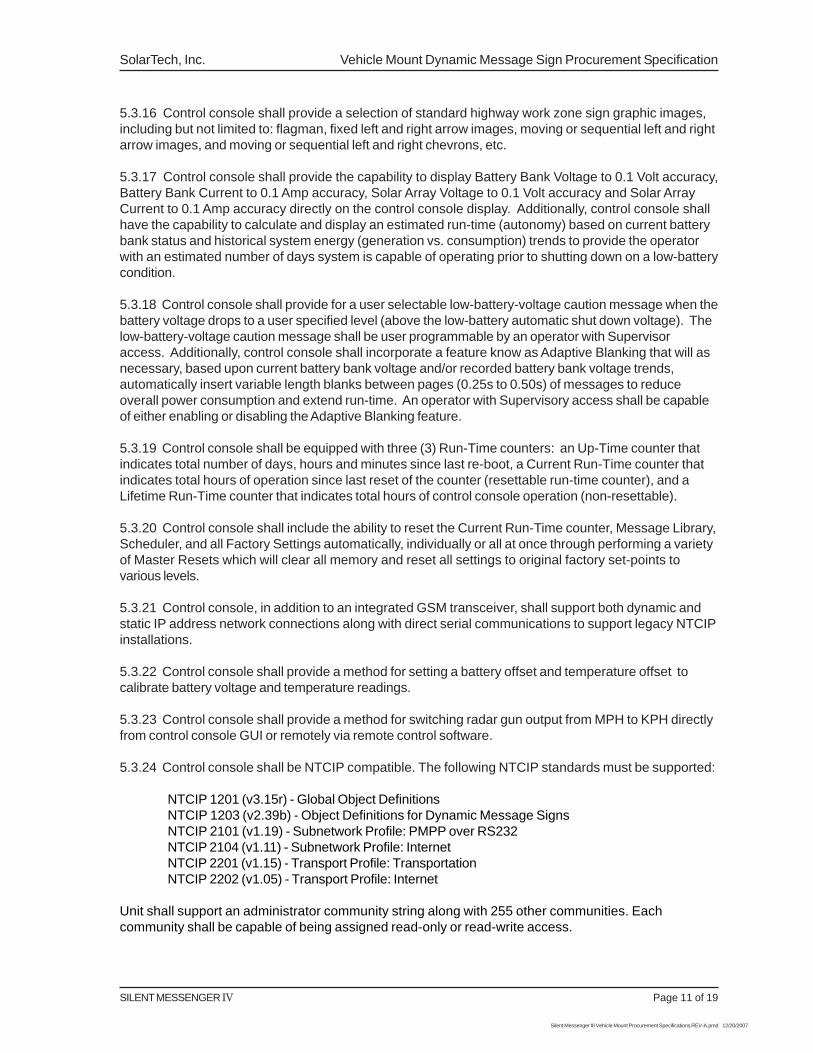
5.3.16 Control console shall provide a selection of standard highway work zone sign graphic images,including but not limited to: flagman, fixed left and right arrow images, moving or sequential left and rightarrow images, and moving or sequential left and right chevrons, etc.
5.3.17 Control console shall provide the capability to display Battery Bank Voltage to 0.1 Volt accuracy,Battery Bank Current to 0.1 Amp accuracy, Solar Array Voltage to 0.1 Volt accuracy and Solar ArrayCurrent to 0.1 Amp accuracy directly on the control console display. Additionally, control console shallhave the capability to calculate and display an estimated run-time (autonomy) based on current batterybank status and historical system energy (generation vs. consumption) trends to provide the operatorwith an estimated number of days system is capable of operating prior to shutting down on a low-batterycondition.
5.3.18 Control console shall provide for a user selectable low-battery-voltage caution message when thebattery voltage drops to a user specified level (above the low-battery automatic shut down voltage). Thelow-battery-voltage caution message shall be user programmable by an operator with Supervisoraccess. Additionally, control console shall incorporate a feature know as Adaptive Blanking that will asnecessary, based upon current battery bank voltage and/or recorded battery bank voltage trends,automatically insert variable length blanks between pages (0.25s to 0.50s) of messages to reduceoverall power consumption and extend run-time. An operator with Supervisory access shall be capableof either enabling or disabling the Adaptive Blanking feature.
5.3.19 Control console shall be equipped with three (3) Run-Time counters: an Up-Time counter thatindicates total number of days, hours and minutes since last re-boot, a Current Run-Time counter thatindicates total hours of operation since last reset of the counter (resettable run-time counter), and aLifetime Run-Time counter that indicates total hours of control console operation (non-resettable).
5.3.20 Control console shall include the ability to reset the Current Run-Time counter, Message Library,Scheduler, and all Factory Settings automatically, individually or all at once through performing a varietyof Master Resets which will clear all memory and reset all settings to original factory set-points tovarious levels.
5.3.21 Control console, in addition to an integrated GSM transceiver, shall support both dynamic andstatic IP address network connections along with direct serial communications to support legacy NTCIPinstallations.
5.3.22 Control console shall provide a method for setting a battery offset and temperature offset tocalibrate battery voltage and temperature readings.
5.3.23 Control console shall provide a method for switching radar gun output from MPH to KPH directlyfrom control console GUI or remotely via remote control software.
5.3.24 Control console shall be NTCIP compatible. The following NTCIP standards must be supported:
NTCIP 1201 (v3.15r) - Global Object DefinitionsNTCIP 1203 (v2.39b) - Object Definitions for Dynamic Message SignsNTCIP 2101 (v1.19) - Subnetwork Profile: PMPP over RS232NTCIP 2104 (v1.11) - Subnetwork Profile: InternetNTCIP 2201 (v1.15) - Transport Profile: TransportationNTCIP 2202 (v1.05) - Transport Profile: Internet
Unit shall support an administrator community string along with 255 other communities. Eachcommunity shall be capable of being assigned read-only or read-write access.
Vehicle Mount Dynamic Message Sign Procurement Specification SolarTech, Inc.
Page 12 of 19 SILENT MESSENGER IV
Silent Messenger III Vehicle Mount Procurement Specifications REV-A.pmd 12/20/2007
Unit shall support up to 65,535 user-defied permanent messages.
Unit shall support a configurable number of changeable (persistent) messages. This number shall beconfigurable between 1 and 65,535, and shall default to 32.
Unit shall support a configurable number of volatile (nonpersistent) messages. This number shall beconfigurable between 1 and 65,535, and shall default to 32.
Each message shall support at least 16 pages.
Unit shall support a scheduler with support for up to 16 schedule, 16 day plans, and 96 day planevents.
Unit shall support at least 255 graphics via the monochrome 1 bit color scheme.
Unit shall support a configurable number of user-definable fonts. This number shall be configurablebetween 1 and 127, and shall default to 32.
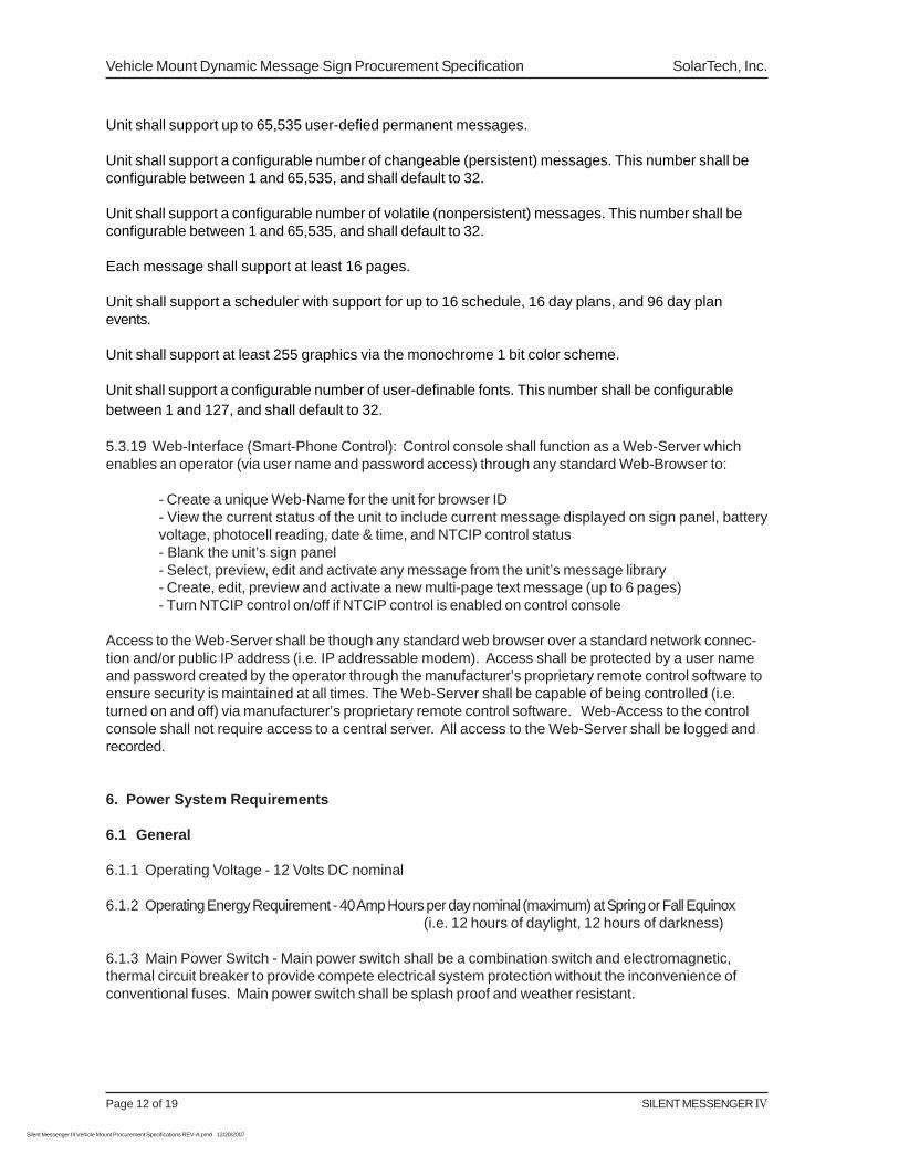
5.3.19 Web-Interface (Smart-Phone Control): Control console shall function as a Web-Server whichenables an operator (via user name and password access) through any standard Web-Browser to:
- Create a unique Web-Name for the unit for browser ID- View the current status of the unit to include current message displayed on sign panel, batteryvoltage, photocell reading, date & time, and NTCIP control status- Blank the unit’s sign panel- Select, preview, edit and activate any message from the unit’s message library- Create, edit, preview and activate a new multi-page text message (up to 6 pages)- Turn NTCIP control on/off if NTCIP control is enabled on control console
Access to the Web-Server shall be though any standard web browser over a standard network connec-tion and/or public IP address (i.e. IP addressable modem). Access shall be protected by a user nameand password created by the operator through the manufacturer’s proprietary remote control software toensure security is maintained at all times. The Web-Server shall be capable of being controlled (i.e.turned on and off) via manufacturer’s proprietary remote control software. Web-Access to the controlconsole shall not require access to a central server. All access to the Web-Server shall be logged andrecorded.
6. Power System Requirements
6.1 General
6.1.1 Operating Voltage - 12 Volts DC nominal
6.1.2 Operating Energy Requirement - 40 Amp Hours per day nominal (maximum) at Spring or Fall Equinox(i.e. 12 hours of daylight, 12 hours of darkness)
6.1.3 Main Power Switch - Main power switch shall be a combination switch and electromagnetic,thermal circuit breaker to provide compete electrical system protection without the inconvenience ofconventional fuses. Main power switch shall be splash proof and weather resistant.
SILENT MESSENGER IV Page 13 of 19
Silent Messenger III Vehicle Mount Procurement Specifications REV-A.pmd 12/20/2007
SolarTech, Inc. Vehicle Mount Dynamic Message Sign Procurement Specification
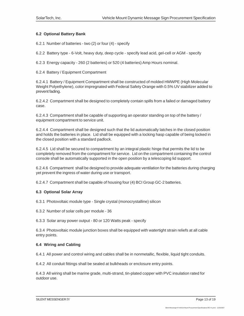
6.2 Optional Battery Bank
6.2.1 Number of batteries - two (2) or four (4) - specify
6.2.2 Battery type - 6-Volt, heavy duty, deep cycle - specify lead acid, gel-cell or AGM - specify
6.2.3 Energy capacity - 260 (2 batteries) or 520 (4 batteries) Amp Hours nominal.
6.2.4 Battery / Equipment Compartment
6.2.4.1 Battery / Equipment Compartment shall be constructed of molded HMWPE (High MolecularWeight Polyethylene), color impregnated with Federal Safety Orange with 0.5% UV stabilizer added toprevent fading.
6.2.4.2 Compartment shall be designed to completely contain spills from a failed or damaged batterycase.
6.2.4.3 Compartment shall be capable of supporting an operator standing on top of the battery /equipment compartment to service unit.
6.2.4.4 Compartment shall be designed such that the lid automatically latches in the closed positionand holds the batteries in place. Lid shall be equipped with a locking hasp capable of being locked inthe closed position with a standard padlock.
6.2.4.5 Lid shall be secured to compartment by an integral plastic hinge that permits the lid to becompletely removed from the compartment for service. Lid on the compartment containing the controlconsole shall be automatically supported in the open position by a telescoping lid support.
6.2.4.6 Compartment shall be designed to provide adequate ventilation for the batteries during chargingyet prevent the ingress of water during use or transport.
6.2.4.7 Compartment shall be capable of housing four (4) BCI Group GC-2 batteries.
6.3 Optional Solar Array
6.3.1 Photovoltaic module type - Single crystal (monocrystalline) silicon
6.3.2 Number of solar cells per module - 36
6.3.3 Solar array power output - 80 or 120 Watts peak - specify
6.3.4 Photovoltaic module junction boxes shall be equipped with watertight strain reliefs at all cableentry points.
6.4 Wiring and Cabling
6.4.1 All power and control wiring and cables shall be in nonmetallic, flexible, liquid tight conduits.
6.4.2 All conduit fittings shall be sealed at bulkheads or enclosure entry points.
6.4.3 All wiring shall be marine grade, multi-strand, tin-plated copper with PVC insulation rated foroutdoor use.
Vehicle Mount Dynamic Message Sign Procurement Specification SolarTech, Inc.
Page 14 of 19 SILENT MESSENGER IV
Silent Messenger III Vehicle Mount Procurement Specifications REV-A.pmd 12/20/2007
6.4.4 All power system wire terminals shall be tin-plated copper to minimize the effects of galvaniccorrosion.
6.4.5 Main power wiring shall be 10 AWG minimum.
6.4.6 Battery terminations shall consist of 5/16-18 UNC marine stud with stainless steel split lockwasher and hex nut with 5/16 tin-plated copper ring terminal.
6.4.7 Solar panel terminations shall consist of stainless steel screws with #8 tin-plated copper snapspade terminal.
6.4.8 All other terminations shall consist of locking-type quick-disconnect connectors with tin-platedterminals for power connections and gold-plated terminals for signal connections. Terminal strips, screwor compression type, shall not be permitted
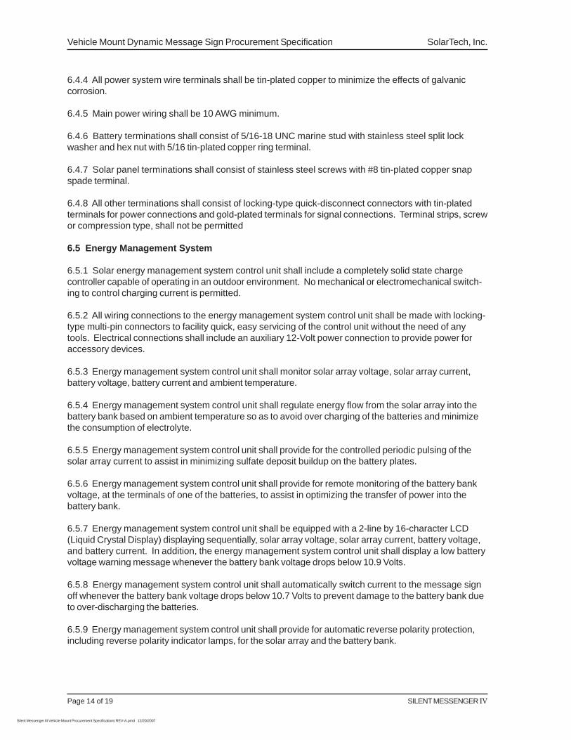
6.5 Energy Management System
6.5.1 Solar energy management system control unit shall include a completely solid state chargecontroller capable of operating in an outdoor environment. No mechanical or electromechanical switch-ing to control charging current is permitted.
6.5.2 All wiring connections to the energy management system control unit shall be made with locking-type multi-pin connectors to facility quick, easy servicing of the control unit without the need of anytools. Electrical connections shall include an auxiliary 12-Volt power connection to provide power foraccessory devices.
6.5.3 Energy management system control unit shall monitor solar array voltage, solar array current,battery voltage, battery current and ambient temperature.
6.5.4 Energy management system control unit shall regulate energy flow from the solar array into thebattery bank based on ambient temperature so as to avoid over charging of the batteries and minimizethe consumption of electrolyte.
6.5.5 Energy management system control unit shall provide for the controlled periodic pulsing of thesolar array current to assist in minimizing sulfate deposit buildup on the battery plates.
6.5.6 Energy management system control unit shall provide for remote monitoring of the battery bankvoltage, at the terminals of one of the batteries, to assist in optimizing the transfer of power into thebattery bank.
6.5.7 Energy management system control unit shall be equipped with a 2-line by 16-character LCD(Liquid Crystal Display) displaying sequentially, solar array voltage, solar array current, battery voltage,and battery current. In addition, the energy management system control unit shall display a low batteryvoltage warning message whenever the battery bank voltage drops below 10.9 Volts.
6.5.8 Energy management system control unit shall automatically switch current to the message signoff whenever the battery bank voltage drops below 10.7 Volts to prevent damage to the battery bank dueto over-discharging the batteries.
6.5.9 Energy management system control unit shall provide for automatic reverse polarity protection,including reverse polarity indicator lamps, for the solar array and the battery bank.
SILENT MESSENGER IV Page 15 of 19
Silent Messenger III Vehicle Mount Procurement Specifications REV-A.pmd 12/20/2007
SolarTech, Inc. Vehicle Mount Dynamic Message Sign Procurement Specification
6.5.10 Energy management system control unit shall provide for automatic fault protection without theneed for fuses. The use of fuses for fault protection shall not be permitted.
6.5.11 Energy managemnt system shall monitor and report to control console battery bank voltage,battery bank load current, solar array voltage and solar array charge current once every 15 seconds.
6.5.12 Energy management system shall have an integrated watchdog timer that is continously resetby the contrtol console during normal operations such that if the control console were to becomeunresponsive due to a software failure/lockup, upon expiration of the timer the energy managementsystem will completely power down and re-start the entire system (including control console and allaccessories such as modem, sign panel compass, etc.) in an attempt to recover the system from atemporary software failure/lockup.
7. Documentation
7.1 Operation and Maintenance Manual - avaiable on-line at www.solartechnology.com
7.1.1 Setup and Operation
7.1.2 Programming
7.1.3 Maintenance
7.1.4 Troubleshooting and Repair
7.1.5 Assembly Diagrams and Parts Lists
7.1.6 Specifications
7.1.7 Appendix
7.2 Command Center - Users Manual - avaiable on-line at www.solartechnology.com
7.2.1 Installation and Setup
7.2.2 Command Center Operation
7.2.3 Appendix
7.3 User Guide - Hard Copy - attached to unit with PVC coated stainless steel lanyard
7.3.1 Pre-transport checklist.
7.3.2 Job site setup checklist.
7.3.3 Basic programming instructions.
7.3.4 Basic system status evaluation.
7.3.5 Weatherproof card attached to unit with nylon-coated stainless steel lanyard.
Vehicle Mount Dynamic Message Sign Procurement Specification SolarTech, Inc.
Page 16 of 19 SILENT MESSENGER IV
Silent Messenger III Vehicle Mount Procurement Specifications REV-A.pmd 12/20/2007
7.4 Integration Support Documentation - Per request from customer support (1-800-475-5442)
7.4.1 Proprietary Protocol Documentation for Custom System Integrators
7.4.2 NTCIP Support Documentation for NTCIP System Integrators
7.4.3 Web-Server Protocol Documentation for Web Based Application System Integrators
8. Maintenance
8.1 Scheduled Maintenance
8.1.1 Solar Array - Clean with water and mild detergent as needed.
8.1.2 Battery Bank - Check electrolyte level once each month and add distilled water as needed.(Note: Not required with Gel-Cell batteries.)
8.2 Preventive Maintenance
8.2.1 Inspect and lubricate axle hubs once per year.
9. Warranty
9.1 Standard Warranty
9.1.1 Bumper to Bumper - Full warranty five (5) years - consult factory for terms & conditions
9.1.2 Solar Panels - Ten years
9.2 Extended Warranty - Consult factory
10. Options
10.1 Battery Charger
10.1.1 Charger type - Switching regulator, constant voltage with automatic switch to maintenance ortrickle charge.
10.1.2 Input Voltage - 110 VAC 50/60 Hz (specify 220 VAC 50 Hz for international use)
10.1.3 Available models with typical recharge times.
10.1.3.1 45-Amp - 36 hours (12 batteries), 24 hours (8 batteries), 12 hours (4 batteries)
10.1.3.2 90-Amp - 22 hours (12 batteries), 16 hours (8 batteries), 8 hours (4 batteries)
10.1.4 Battery charger unit shall install in the field with minimum effort.
SILENT MESSENGER IV Page 17 of 19
Silent Messenger III Vehicle Mount Procurement Specifications REV-A.pmd 12/20/2007
SolarTech, Inc. Vehicle Mount Dynamic Message Sign Procurement Specification
10.2 Remote Control
10.2.1 General
10.2.1.1 The remote control option shall provide for complete control of all dynamic message signfunctions. The remote control option shall, at a minimum, provide for:
- Simultaneously geographically tracking, managing, operating and maintaining a minimum of1,000 remotely located PCMS units including setting up automatic e-mail notifications/alerts forunit movement, change of displayed message, low estimated runtime, low battery condition,sign panel failures, and pixel failures.
- Sending a message to one or more remote PCMS for immediate display.
- Receiving the message currently displayed on all remote PCMS.
- Managing the message libraries and message schedules & events on all remote PCMS.
- Checking the operating status, including sign panel status, system date & time, battery voltage,estimated autonomy, temperature, unit Up-Time, Current Run-Time, Life-Time Run-Time, andambient light level of all remote PCMS.
- Reporting and managing NTCIP status of all PCMS.
- Retrieve up to 30 days worth of logged Radar Statistics from units equipped with optionalRadar Speed Monitor (see section 10.3 for optional Radar Speed Monitor).
- Provide for the ability to perform various system resets including a complete re-boot/restart ofthe system for all PCMS.
10.2.1.3 Communication Protocol - Proprietary with complete CRC error detection and correction andfull challenge-response password authentication.
10.2.1.4 Data Format - Data is encrypted and compressed for added security and reliability.
10.2.1.5 All operating software for message sign control console and host computer shall be includedwith basic message sign package (downloadable from www.solartechnology.com).
10.2.2 TCP/IP Network Communications (Dynamic or Static IP Address)
10.2.2.1 Data rate - 10/100 Base-T Ethernet
10.2.2.2 Remote control of any networked (IP addressable) PCMS may be achieved from any hostcomputer with Internet connectivity (either with standard NTCIP commands via SNMP or STMP, or withComamnd Center). Remote control software (Command Center) shall be provided free of charge(downloadable from www.solartechnology.com) with unit and function on any host computer, indepen-dent of operating system. Control console and remote control software shall incorporate a challenge/response encrypted type password security system to prevent unauthorized access of any networkedPCMS.
Vehicle Mount Dynamic Message Sign Procurement Specification SolarTech, Inc.
Page 18 of 19 SILENT MESSENGER IV
Silent Messenger III Vehicle Mount Procurement Specifications REV-A.pmd 12/20/2007
10.2.3 IP Addressable Cellular Transceiver Operation
10.2.3.1 Wireless modem with up to a 3-Watt cellular transceiver.
10.2.3.2 MNP 2-4 Error Control - Automatic error detection and correction.
10.2.3.3 MNP 5 Data Compression - Higher data rates, shorter connection times.
10.2.3.4 MNP 10EC - Enhanced performance over noisy cellular connections.
10.3 Radar Speed Monitor
10.3.1 General
10.3.1.1 Operating Frequency - 24.15 GHz (K-Band)
10.3.1.2 Antenna Beamwidth - 120 (Circular Pattern)
10.3.1.3 Capture Angle - 16.50 typical (Circular Pattern)
10.3.1.4 Target Speed Range - 5 to 125 MPH (20 to 200 km/h)
10.3.1.5 Target Speed Accuracy - 1 MPH typical
10.3.1.6 Detection Distance - 1,500 Feet (Automobile-size target)
10.3.1.7 Radar unit shall install in the field with minimum effort.
10.3.1.8 Message sign shall be pre-wired and pre-programmed for radar speed monitor option.
10.3.2 Operating Features
10.3.2.1 Target Speed Display - The speed of the target may be displayed as part of any user-createdmessages, in any character size, in any position in the message. Multiple messages which includetarget speed can be stored in the message library.
10.3.2.2 Triggered Display - A message may be displayed only when an acquired target exceeds apreset speed threshold. This message may include the display of the target speed. If no target isacquired or if the acquired target is below the preset threshold, the default message will be displayed.Default message can be a blank display.
10.3.2.3 Window Triggered Display - Upper and lower speed thresholds may be preset such that thespecial message is displayed only when the target speed is above the lower threshold but below theupper threshold. This message can include the display of the target speed. If no target is acquired or ifthe acquired target is above or below the preset thresholds, the default message will be displayed.Default message can be a blank display. Multiple windows can be programmed each with a differentmessage to be displayed when the acquired target speed is above the minimum speed but below themaximum speed threshold for that particular window. Each of these messages can include the displayof the target speed.
10.3.2.4 All necessary software features shall be included with the basic message sign package.
SILENT MESSENGER IV Page 19 of 19
Silent Messenger III Vehicle Mount Procurement Specifications REV-A.pmd 12/20/2007
SolarTech, Inc. Vehicle Mount Dynamic Message Sign Procurement Specification
10.3.3 Radar Statistical Data Collection
10.3.3.1 Control Console shall automatically log and record (to a standard USB memory stick) all rawdata provided by the radar gun along with basic statistical information about the collected data in 15minute intervals. The data shall be stored in two CSV (Comma Separated Value) files which may beopened in Microsoft Excel or any other similar spreadsheet type application for viewing, manipulationand analysis. Additionally, the most recent 30 days worth of Radar Statistics (statistical radar datalogged every 15 minutes) shall be maintained in the control consoles nonvolatile memory and shall beretrieved remotely via Control Center 3000 - see Control Center 3000 manual for further details.
10.3.3.2 Data Provided
10.3.3.2.1 Raw Data File: (radar_data file) - (Year, Month, Day, Time, Reading) - every reading -readings recorded every 250ms while tracking a target
10.3.3.2.2 Statistical Data File: (radar_statistics file) - (Year, Month, Day, Time, # of Readings, Mean,Median, Mode, Standard Deviation, Lowest Reading, Highest Reading) - based on all readings - readingsare taken every 250ms while tracking a target
10.4 Cellular Transceiver & GPS Receiver Module
10.4.1 Integrated into Control Console - proprietary
10.5 Sign Panel Flux-Gate Digital Compass
10.5.1 General
10.5.1.1 Operating Voltage: 8-28 Vdc
10.5.1.2 Input Current: 40 mA @ 12 Vdc maximum
10.5.1.3 Operating Temperature Range: -40C to +65C (-40F to +150F)
10.5.1.4 Shock/Vibration: meets MIL-STD-810 requirements
10.5.1.5 Altitude: 40,000 ft. maximum
10.5.1.6 Reliability: MTBF > 30,000 hours
10.5.1.7 Accuracy: +/-0.5 degrees
10.5.1.8 Repeatability: +/-0.2 degrees
10.5.1.9 Resolution: 0.1 degrees
10.5.1.10 Dip Angle: +/-80 degrees
10.5.1.11 Tilt Angle: +/-16 degrees
10.5.1.12 Response Time: 1 second