SILENCED SCREW ROTARY COMPRESSOR UNITS HP 10 - 15 - 20 ... · MANUAL USE AND MAINTENANCE SILENCED...
55
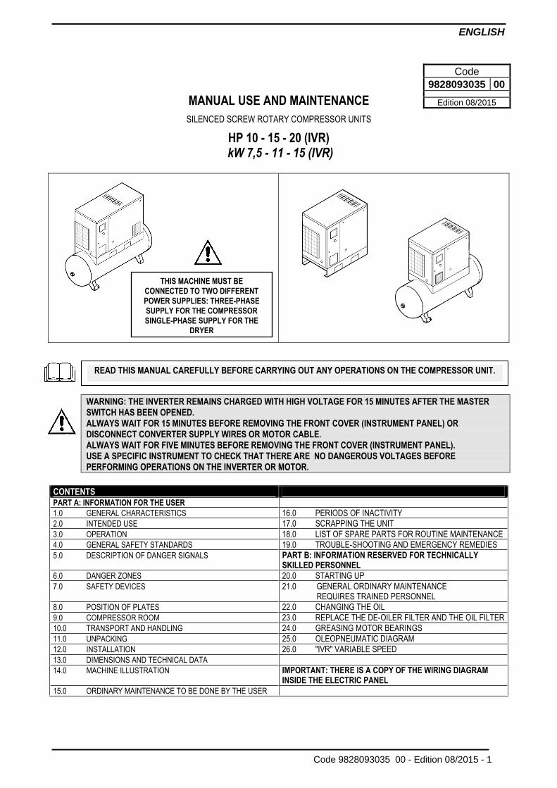
ENGLISH Code 9828093035 00 - Edition 08/2015 - 1 MANUAL USE AND MAINTENANCE SILENCED SCREW ROTARY COMPRESSOR UNITS HP 10 - 15 - 20 (IVR) kW 7,5 - 11 - 15 (IVR) WARNING: THE INVERTER REMAINS CHARGED WITH HIGH VOLTAGE FOR 15 MINUTES AFTER THE MASTER SWITCH HAS BEEN OPENED. ALWAYS WAIT FOR 15 MINUTES BEFORE REMOVING THE FRONT COVER (INSTRUMENT PANEL) OR DISCONNECT CONVERTER SUPPLY WIRES OR MOTOR CABLE. ALWAYS WAIT FOR FIVE MINUTES BEFORE REMOVING THE FRONT COVER (INSTRUMENT PANEL). USE A SPECIFIC INSTRUMENT TO CHECK THAT THERE ARE NO DANGEROUS VOLTAGES BEFORE PERFORMING OPERATIONS ON THE INVERTER OR MOTOR. CONTENTS PART A: INFORMATION FOR THE USER 1.0 GENERAL CHARACTERISTICS 16.0 PERIODS OF INACTIVITY 2.0 INTENDED USE 17.0 SCRAPPING THE UNIT 3.0 OPERATION 18.0 LIST OF SPARE PARTS FOR ROUTINE MAINTENANCE 4.0 GENERAL SAFETY STANDARDS 19.0 TROUBLE-SHOOTING AND EMERGENCY REMEDIES 5.0 DESCRIPTION OF DANGER SIGNALS PART B: INFORMATION RESERVED FOR TECHNICALLY SKILLED PERSONNEL 6.0 DANGER ZONES 20.0 STARTING UP 7.0 SAFETY DEVICES 21.0 GENERAL ORDINARY MAINTENANCE REQUIRES TRAINED PERSONNEL 8.0 POSITION OF PLATES 22.0 CHANGING THE OIL 9.0 COMPRESSOR ROOM 23.0 REPLACE THE DE-OILER FILTER AND THE OIL FILTER 10.0 TRANSPORT AND HANDLING 24.0 GREASING MOTOR BEARINGS 11.0 UNPACKING 25.0 OLEOPNEUMATIC DIAGRAM 12.0 INSTALLATION 26.0 "IVR" VARIABLE SPEED 13.0 DIMENSIONS AND TECHNICAL DATA 14.0 MACHINE ILLUSTRATION IMPORTANT: THERE IS A COPY OF THE WIRING DIAGRAM INSIDE THE ELECTRIC PANEL 15.0 ORDINARY MAINTENANCE TO BE DONE BY THE USER Code 9828093035 00 Edition 08/2015 READ THIS MANUAL CAREFULLY BEFORE CARRYING OUT ANY OPERATIONS ON THE COMPRESSOR UNIT. THIS MACHINE MUST BE CONNECTED TO TWO DIFFERENT POWER SUPPLIES: THREE-PHASE SUPPLY FOR THE COMPRESSOR SINGLE-PHASE SUPPLY FOR THE DRYER
Transcript of SILENCED SCREW ROTARY COMPRESSOR UNITS HP 10 - 15 - 20 ... · MANUAL USE AND MAINTENANCE SILENCED...
ENGLISH
Code 9828093035 00 - Edition 08/2015 - 1
MANUAL USE AND MAINTENANCE
SILENCED SCREW ROTARY COMPRESSOR UNITS
HP 10 - 15 - 20 (IVR) kW 7,5 - 11 - 15 (IVR)
WARNING: THE INVERTER REMAINS CHARGED WITH HIGH VOLTAGE FOR 15 MINUTES AFTER THE MASTER SWITCH HAS BEEN OPENED. ALWAYS WAIT FOR 15 MINUTES BEFORE REMOVING THE FRONT COVER (INSTRUMENT PANEL) OR DISCONNECT CONVERTER SUPPLY WIRES OR MOTOR CABLE. ALWAYS WAIT FOR FIVE MINUTES BEFORE REMOVING THE FRONT COVER (INSTRUMENT PANEL). USE A SPECIFIC INSTRUMENT TO CHECK THAT THERE ARE NO DANGEROUS VOLTAGES BEFORE PERFORMING OPERATIONS ON THE INVERTER OR MOTOR.
CONTENTS PART A: INFORMATION FOR THE USER
1.0 GENERAL CHARACTERISTICS 16.0 PERIODS OF INACTIVITY
2.0 INTENDED USE 17.0 SCRAPPING THE UNIT
3.0 OPERATION 18.0 LIST OF SPARE PARTS FOR ROUTINE MAINTENANCE
4.0 GENERAL SAFETY STANDARDS 19.0 TROUBLE-SHOOTING AND EMERGENCY REMEDIES
5.0 DESCRIPTION OF DANGER SIGNALS PART B: INFORMATION RESERVED FOR TECHNICALLY SKILLED PERSONNEL
6.0 DANGER ZONES 20.0 STARTING UP
7.0 SAFETY DEVICES 21.0 GENERAL ORDINARY MAINTENANCE REQUIRES TRAINED PERSONNEL
8.0 POSITION OF PLATES 22.0 CHANGING THE OIL
9.0 COMPRESSOR ROOM 23.0 REPLACE THE DE-OILER FILTER AND THE OIL FILTER
10.0 TRANSPORT AND HANDLING 24.0 GREASING MOTOR BEARINGS
11.0 UNPACKING 25.0 OLEOPNEUMATIC DIAGRAM
12.0 INSTALLATION 26.0 "IVR" VARIABLE SPEED
13.0 DIMENSIONS AND TECHNICAL DATA
14.0 MACHINE ILLUSTRATION IMPORTANT: THERE IS A COPY OF THE WIRING DIAGRAM INSIDE THE ELECTRIC PANEL
15.0 ORDINARY MAINTENANCE TO BE DONE BY THE USER
Code
9828093035 00
Edition 08/2015
READ THIS MANUAL CAREFULLY BEFORE CARRYING OUT ANY OPERATIONS ON THE COMPRESSOR UNIT.
THIS MACHINE MUST BE
CONNECTED TO TWO DIFFERENT
POWER SUPPLIES: THREE-PHASE
SUPPLY FOR THE COMPRESSOR
SINGLE-PHASE SUPPLY FOR THE
DRYER
ENGLISH
2 - Edition 08/2015 Code 9828093035 00 -
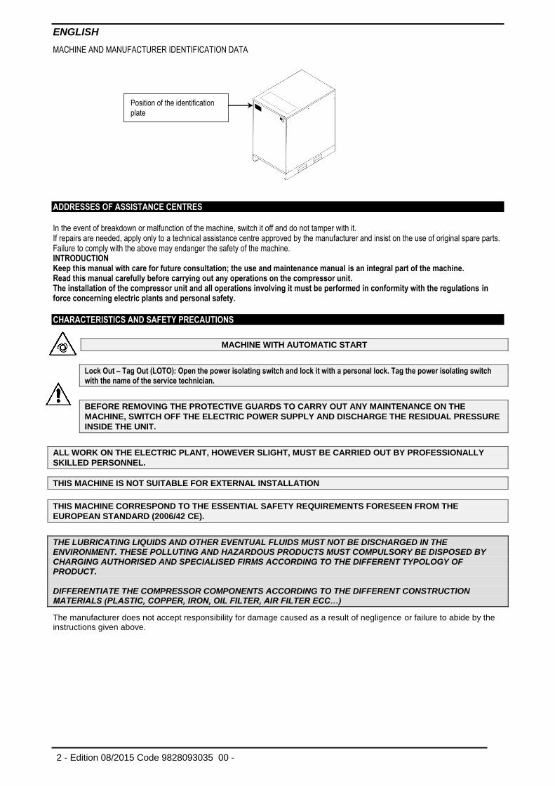
MACHINE AND MANUFACTURER IDENTIFICATION DATA
ADDRESSES OF ASSISTANCE CENTRES In the event of breakdown or malfunction of the machine, switch it off and do not tamper with it. If repairs are needed, apply only to a technical assistance centre approved by the manufacturer and insist on the use of original spare parts. Failure to comply with the above may endanger the safety of the machine. INTRODUCTION Keep this manual with care for future consultation; the use and maintenance manual is an integral part of the machine. Read this manual carefully before carrying out any operations on the compressor unit. The installation of the compressor unit and all operations involving it must be performed in conformity with the regulations in force concerning electric plants and personal safety. CHARACTERISTICS AND SAFETY PRECAUTIONS
MACHINE WITH AUTOMATIC START
Lock Out – Tag Out (LOTO): Open the power isolating switch and lock it with a personal lock. Tag the power isolating switch
with the name of the service technician.
BEFORE REMOVING THE PROTECTIVE GUARDS TO CARRY OUT ANY MAINTENANCE ON THE
MACHINE, SWITCH OFF THE ELECTRIC POWER SUPPLY AND DISCHARGE THE RESIDUAL PRESSURE
INSIDE THE UNIT.
ALL WORK ON THE ELECTRIC PLANT, HOWEVER SLIGHT, MUST BE CARRIED OUT BY PROFESSIONALLY
SKILLED PERSONNEL.
THIS MACHINE IS NOT SUITABLE FOR EXTERNAL INSTALLATION
THIS MACHINE CORRESPOND TO THE ESSENTIAL SAFETY REQUIREMENTS FORESEEN FROM THE
EUROPEAN STANDARD (2006/42 CE).
THE LUBRICATING LIQUIDS AND OTHER EVENTUAL FLUIDS MUST NOT BE DISCHARGED IN THE ENVIRONMENT. THESE POLLUTING AND HAZARDOUS PRODUCTS MUST COMPULSORY BE DISPOSED BY CHARGING AUTHORISED AND SPECIALISED FIRMS ACCORDING TO THE DIFFERENT TYPOLOGY OF PRODUCT. DIFFERENTIATE THE COMPRESSOR COMPONENTS ACCORDING TO THE DIFFERENT CONSTRUCTION MATERIALS (PLASTIC, COPPER, IRON, OIL FILTER, AIR FILTER ECC…)
The manufacturer does not accept responsibility for damage caused as a result of negligence or failure to abide by the instructions given above.
Position of the identification
plate
ENGLISH
Code 9828093035 00 - Edition 08/2015 - 3
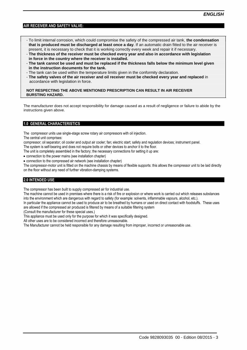
AIR RECEIVER AND SAFETY VALVE:
- To limit internal corrosion, which could compromise the safety of the compressed air tank, the condensation that is produced must be discharged at least once a day. If an automatic drain fitted to the air receiver is present, it is necessary to check that it is working correctly every week and repair it if necessary.
- The thickness of the receiver must be checked every year and also in accordance with legislation
in force in the country where the receiver is installed.
- The tank cannot be used and must be replaced if the thickness falls below the minimum level given
in the instruction documents for the tank. - The tank can be used within the temperature limits given in the conformity declaration. - The safety valves of the air receiver and oil receiver must be checked every year and replaced in
accordance with legislation in force.
NOT RESPECTING THE ABOVE MENTIONED PRESCRIPTION CAN RESULT IN AIR RECEIVER BURSTING HAZARD.
The manufacturer does not accept responsibility for damage caused as a result of negligence or failure to abide by the instructions given above.
1.0 GENERAL CHARACTERISTICS
The compressor units use single-stage screw rotary air compressors with oil injection. The central unit comprises: compressor; oil separator; oil cooler and output air cooler; fan; electric start; safety and regulation devices; instrument panel. The system is self-bearing and does not require bolts or other devices to anchor it to the floor. The unit is completely assembled in the factory; the necessary connections for setting it up are:
connection to the power mains (see installation chapter)
connection to the compressed air network (see installation chapter) The compressor-motor unit is fitted on the machine chassis by means of flexible supports: this allows the compressor unit to be laid directly on the floor without any need of further vibration-damping systems.
2.0 INTENDED USE The compressor has been built to supply compressed air for industrial use. The machine cannot be used in premises where there is a risk of fire or explosion or where work is carried out which releases substances into the environment which are dangerous with regard to safety (for example: solvents, inflammable vapours, alcohol, etc.). In particular the appliance cannot be used to produce air to be breathed by humans or used on direct contact with foodstuffs. These uses are allowed if the compressed air produced is filtered by means of a suitable filtering system (Consult the manufacturer for these special uses.) This appliance must be used only for the purpose for which it was specifically designed. All other uses are to be considered incorrect and therefore unreasonable. The Manufacturer cannot be held responsible for any damage resulting from improper, incorrect or unreasonable use.
ENGLISH
4 - Edition 08/2015 Code 9828093035 00 -
3.0 OPERATION
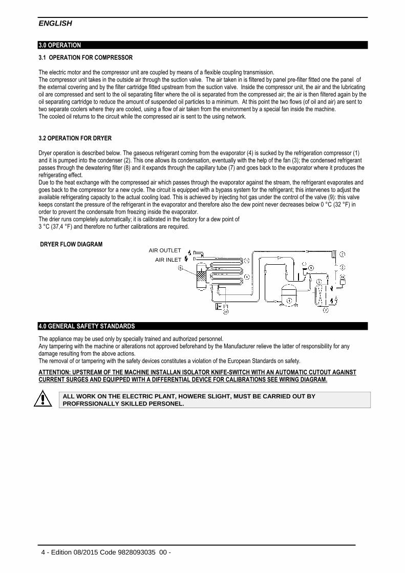
3.1 OPERATION FOR COMPRESSOR The electric motor and the compressor unit are coupled by means of a flexible coupling transmission. The compressor unit takes in the outside air through the suction valve. The air taken in is filtered by panel pre-filter fitted one the panel of the external covering and by the filter cartridge fitted upstream from the suction valve. Inside the compressor unit, the air and the lubricating oil are compressed and sent to the oil separating filter where the oil is separated from the compressed air; the air is then filtered again by the oil separating cartridge to reduce the amount of suspended oil particles to a minimum. At this point the two flows (of oil and air) are sent to two separate coolers where they are cooled, using a flow of air taken from the environment by a special fan inside the machine. The cooled oil returns to the circuit while the compressed air is sent to the using network. 3.2 OPERATION FOR DRYER Dryer operation is described below. The gaseous refrigerant coming from the evaporator (4) is sucked by the refrigeration compressor (1) and it is pumped into the condenser (2). This one allows its condensation, eventually with the help of the fan (3); the condensed refrigerant passes through the dewatering filter (8) and it expands through the capillary tube (7) and goes back to the evaporator where it produces the refrigerating effect. Due to the heat exchange with the compressed air which passes through the evaporator against the stream, the refrigerant evaporates and goes back to the compressor for a new cycle. The circuit is equipped with a bypass system for the refrigerant; this intervenes to adjust the available refrigerating capacity to the actual cooling load. This is achieved by injecting hot gas under the control of the valve (9): this valve keeps constant the pressure of the refrigerant in the evaporator and therefore also the dew point never decreases below 0 °C (32 °F) in order to prevent the condensate from freezing inside the evaporator. The drier runs completely automatically; it is calibrated in the factory for a dew point of 3 °C (37,4 °F) and therefore no further calibrations are required.
DRYER FLOW DIAGRAM
4.0 GENERAL SAFETY STANDARDS
The appliance may be used only by specially trained and authorized personnel. Any tampering with the machine or alterations not approved beforehand by the Manufacturer relieve the latter of responsibility for any damage resulting from the above actions. The removal of or tampering with the safety devices constitutes a violation of the European Standards on safety.
ATTENTION: UPSTREAM OF THE MACHINE INSTALLAN ISOLATOR KNIFE-SWITCH WITH AN AUTOMATIC CUTOUT AGAINST CURRENT SURGES AND EQUIPPED WITH A DIFFERENTIAL DEVICE FOR CALIBRATIONS SEE WIRING DIAGRAM.
ALL WORK ON THE ELECTRIC PLANT, HOWERE SLIGHT, MUST BE CARRIED OUT BY
PROFRSSIONALLY SKILLED PERSONEL.
AIR INLET AIR OUTLET
ENGLISH
Code 9828093035 00 - Edition 08/2015 - 5
5.0 DESCRIPTION OF DANGER SIGNALS
1) FLUID EJECTION
6) HOT PARTS
2) DANGEROUS ELECTRIC VOLTAGE
7) MOVING PARTS
3) AIR NOT FIT FOR BREATHING
8) FAN ROTATING
4) NOISE
9) MACHINE WITH AUTOMATIC START
5) HIGH PRESSURE
10) PURGE EVERY DAY
5.1 DESCRIPTION OF COMPULSORY SIGNALS
10) READ THE USE AND MAINTENANCE
INSTRUCTIONS
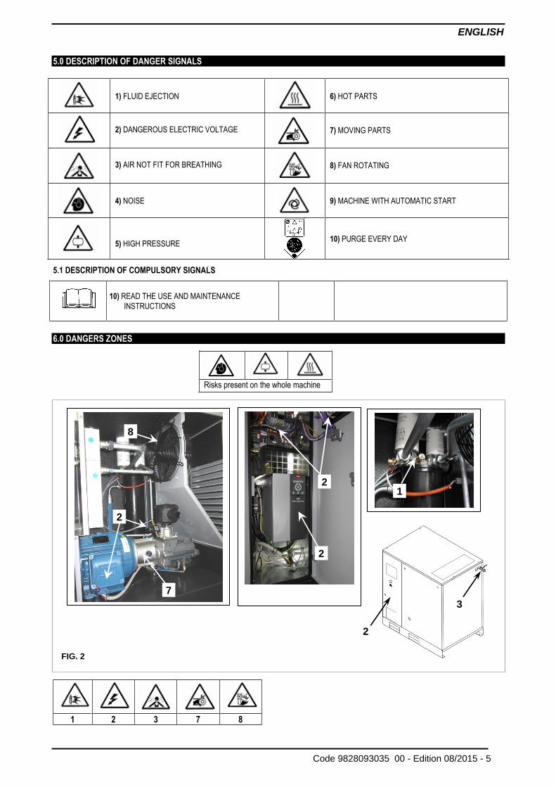
6.0 DANGERS ZONES
Risks present on the whole machine
1 2 3 7 8
2
2
2
8
1
7
FIG. 2
3
2
ENGLISH
6 - Edition 08/2015 Code 9828093035 00 -
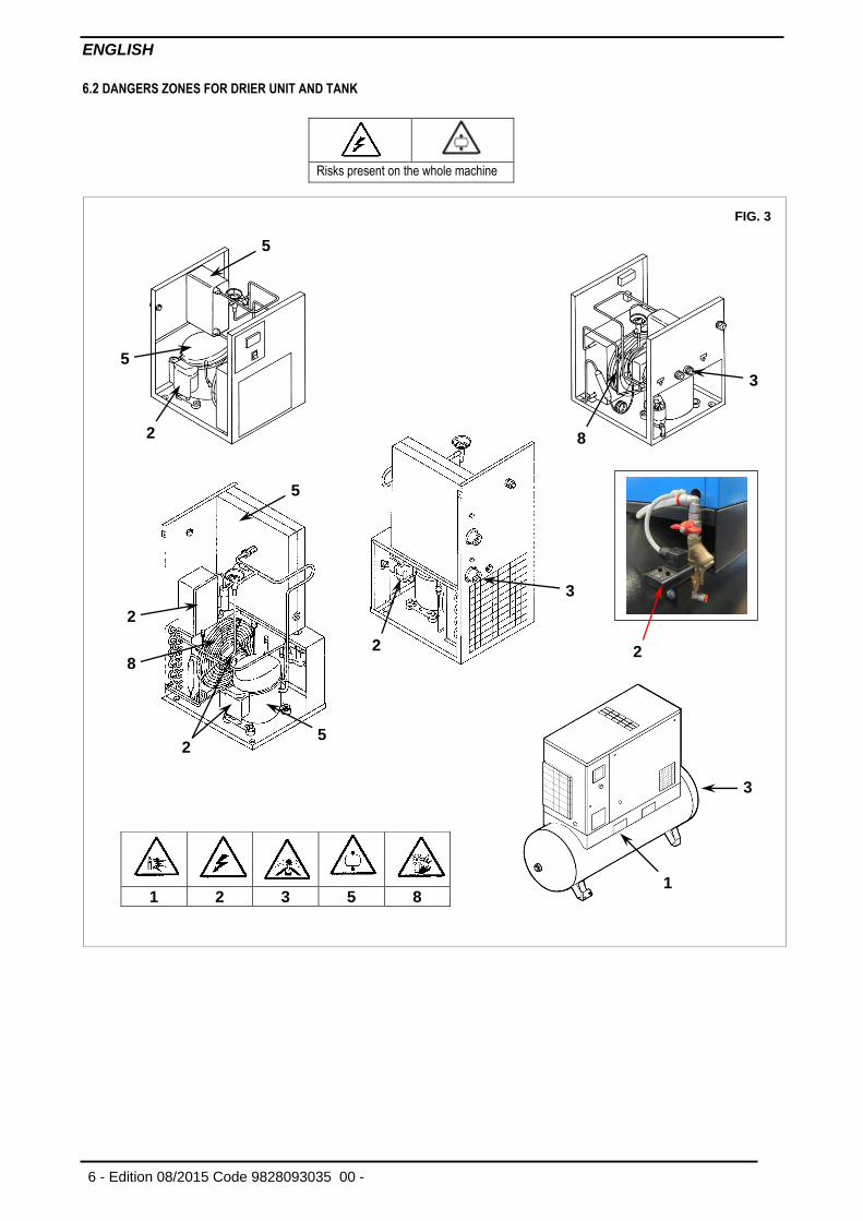
6.2 DANGERS ZONES FOR DRIER UNIT AND TANK
Risks present on the whole machine
1 2 3 5 8
FIG. 3
5
5
2
3
8
3
2
5
2
2 5
8
2
3
1
ENGLISH
Code 9828093035 00 - Edition 08/2015 - 7
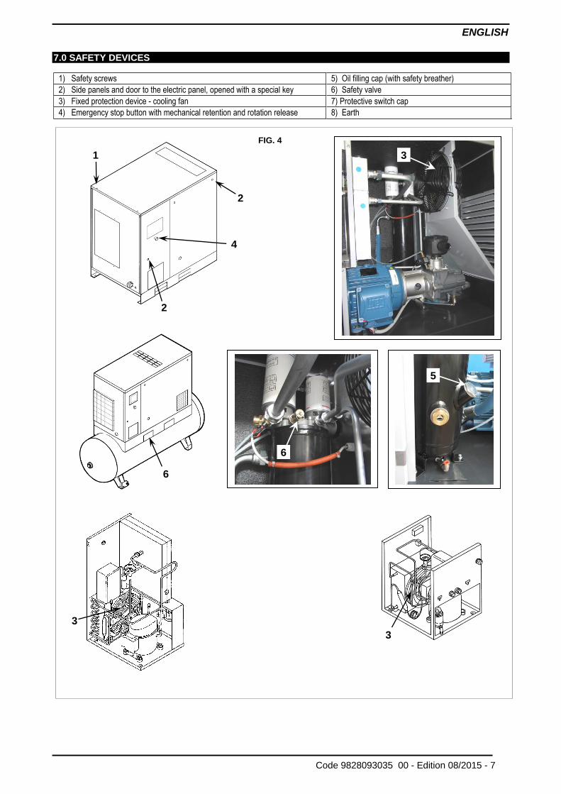
7.0 SAFETY DEVICES
1) Safety screws 5) Oil filling cap (with safety breather)
2) Side panels and door to the electric panel, opened with a special key 6) Safety valve
3) Fixed protection device - cooling fan 7) Protective switch cap
4) Emergency stop button with mechanical retention and rotation release 8) Earth
FIG. 4
3
6
5
3
3
2
4
1
2
6
ENGLISH
8 - Edition 08/2015 Code 9828093035 00 -
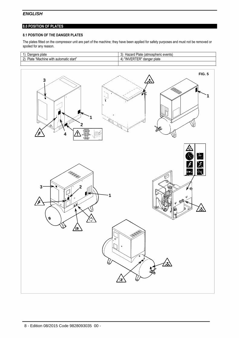
8.0 POSITION OF PLATES 8.1 POSITION OF THE DANGER PLATES
The plates fitted on the compressor unit are part of the machine; they have been applied for safety purposes and must not be removed or spoiled for any reason.
1) Dangers plate 3) Hazard Plate (atmospheric events)
2) Plate “Machine with automatic start” 4) "INVERTER" danger plate
FIG. 5
1
1
3
2
4
3
1
2
ENGLISH
Code 9828093035 00 - Edition 08/2015 - 9
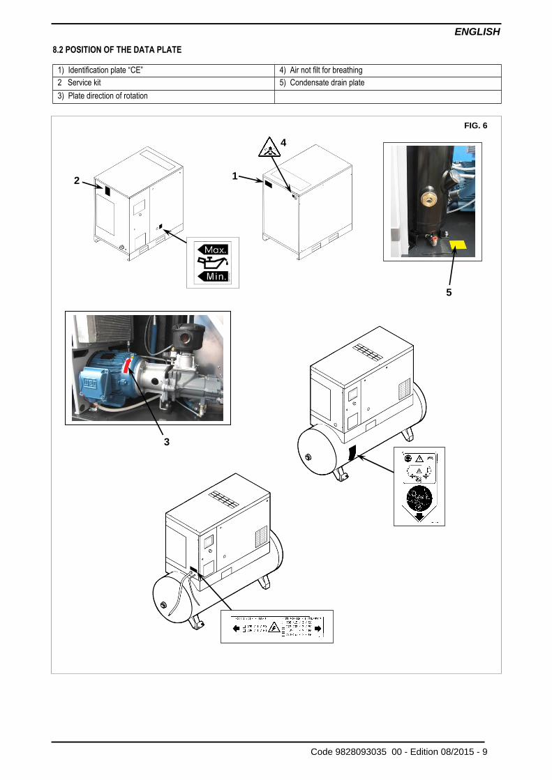
8.2 POSITION OF THE DATA PLATE
1) Identification plate “CE” 4) Air not filt for breathing
2 Service kit 5) Condensate drain plate
3) Plate direction of rotation
FIG. 6
3
5
1
2
4
ENGLISH
10 - Edition 08/2015 Code 9828093035 00 -
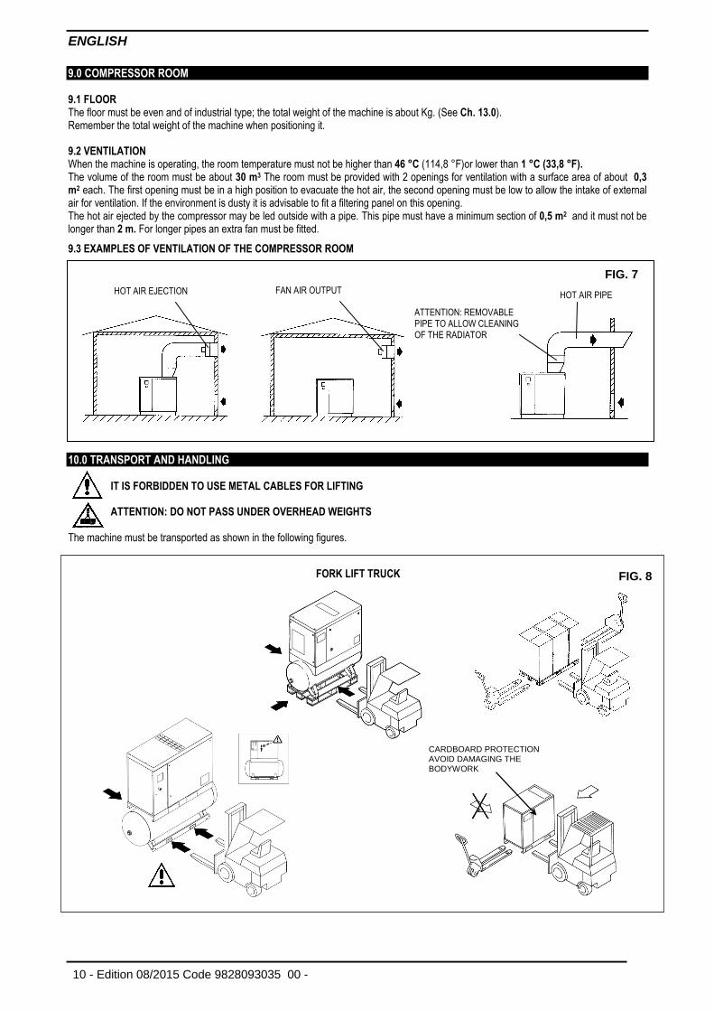
9.0 COMPRESSOR ROOM 9.1 FLOOR The floor must be even and of industrial type; the total weight of the machine is about Kg. (See Ch. 13.0). Remember the total weight of the machine when positioning it. 9.2 VENTILATION When the machine is operating, the room temperature must not be higher than 46 °C (114,8 °F)or lower than 1 °C (33,8 °F). The volume of the room must be about 30 m3 The room must be provided with 2 openings for ventilation with a surface area of about 0,3 m2 each. The first opening must be in a high position to evacuate the hot air, the second opening must be low to allow the intake of external air for ventilation. If the environment is dusty it is advisable to fit a filtering panel on this opening. The hot air ejected by the compressor may be led outside with a pipe. This pipe must have a minimum section of 0,5 m2 and it must not be longer than 2 m. For longer pipes an extra fan must be fitted.
9.3 EXAMPLES OF VENTILATION OF THE COMPRESSOR ROOM
10.0 TRANSPORT AND HANDLING
IT IS FORBIDDEN TO USE METAL CABLES FOR LIFTING
ATTENTION: DO NOT PASS UNDER OVERHEAD WEIGHTS The machine must be transported as shown in the following figures.
RFC 5-7-10
FIG. 7
HOT AIR EJECTION HOT AIR PIPE FAN AIR OUTPUT
ATTENTION: REMOVABLE PIPE TO ALLOW CLEANING OF THE RADIATOR
FORK LIFT TRUCK
FIG. 8
CARDBOARD PROTECTION AVOID DAMAGING THE BODYWORK
ENGLISH
Code 9828093035 00 - Edition 08/2015 - 11
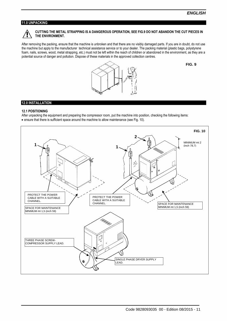
11.0 UNPACKING
CUTTING THE METAL STRAPPING IS A DANGEROUS OPERATION, SEE FIG.9 DO NOT ABANDON THE CUT PIECES IN THE ENVIRONMENT.
After removing the packing, ensure that the machine is unbroken and that there are no visibly damaged parts. If you are in doubt, do not use the machine but apply to the manufacturer technical assistance service or to your dealer. The packing material (plastic bags, polystyrene foam, nails, screws, wood, metal strapping, etc.) must not be left within the reach of children or abandoned in the environment, as they are a potential source of danger and pollution. Dispose of these materials in the approved collection centres.
12.0 INSTALLATION 12.1 POSITIONING After unpacking the equipment and preparing the compressor room, put the machine into position, checking the following items:
ensure that there is sufficient space around the machine to allow maintenance (see Fig. 10).
FIG. 9
FIG. 10
1
PROTECT THE POWER CABLE WITH A SUITABLE CHANNEL.
SPACE FOR MAINTENANCE MINIMUM mt 1,5 (inch 59)
THREE PHASE SCREW-COMPRESSOR SUPPLY LEAD.
1
2
MINIMUM mt 2 (inch 78,7)
SPACE FOR MAINTENANCE MINIMUM mt 1,5 (inch 59)
PROTECT THE POWER CABLE WITH A SUITABLE CHANNEL.
SINGLE PHASE DRYER SUPPLY LEAD.
ENGLISH
12 - Edition 08/2015 Code 9828093035 00 -
ENSURE THAT THE OPERATOR CAN SEE THE WHOLE MACHINE FROM THE CONTROL PANEL AND CHECK THE PRESENCE OF ANY UNAUTHORIZED PERSONS IN THE VICINITY OF THE MACHINE.
12.2 ELECTRICAL CONNECTION
Check that the supply voltage is the same as the value indicated on the machine data plate.
Check the condition of the line leads and ensure that there is an efficient earth lead.
Ensure that there is an automatic cut-out device upstream for the machine against overcurrents,with a differential device (see Ref. 1 for compresseur Ref. 2 for dryer ) wiring diagram.
Connect the machine power cables with the greatest care, according to the standards in force. These cables must be as indicated on the machine wiring diagram.
After the first 50 working hours, check that the screws on the electric terminals are tight.
ONLY PROFESSIONALLY SKILLED PERSONNEL MAY HAVE ACCESS TO THE ELECTRIC PANEL. SWITCH OFF THE POWER BEFORE OPENING THE DOOR OF THE ELECTRIC PANEL.
COMPLIANCE WITH THE REGULATIONS IN FORCE CONCERNING ELECTRIC PLANTS IS FUNDAMENTAL FOR OPERATOR SAFETY AND FOR THE PROTECTION OF THE MACHINE
CABLES, PLUGS AND ALL OTHER TYPE OF ELECTRIC MATERIAL USED FOR THE CONNECTION MUST BE SUITABLE FOR THE USE AND COMPLYING WITH THE REQUIREMENTS STATED BY THE REGULATIONS IN FORCE.
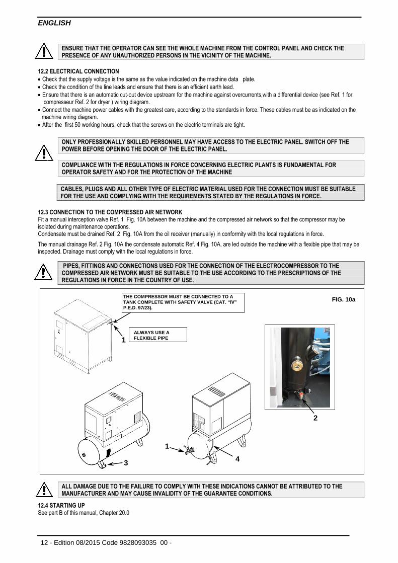
12.3 CONNECTION TO THE COMPRESSED AIR NETWORK Fit a manual interception valve Ref. 1 Fig. 10A between the machine and the compressed air network so that the compressor may be isolated during maintenance operations. Condensate must be drained Ref. 2 Fig. 10A from the oil receiver (manually) in conformity with the local regulations in force.
The manual drainage Ref. 2 Fig. 10A the condensate automatic Ref. 4 Fig. 10A, are led outside the machine with a flexible pipe that may be inspected. Drainage must comply with the local regulations in force.
PIPES, FITTINGS AND CONNECTIONS USED FOR THE CONNECTION OF THE ELECTROCOMPRESSOR TO THE COMPRESSED AIR NETWORK MUST BE SUITABLE TO THE USE ACCORDING TO THE PRESCRIPTIONS OF THE REGULATIONS IN FORCE IN THE COUNTRY OF USE.
ALL DAMAGE DUE TO THE FAILURE TO COMPLY WITH THESE INDICATIONS CANNOT BE ATTRIBUTED TO THE MANUFACTURER AND MAY CAUSE INVALIDITY OF THE GUARANTEE CONDITIONS.
12.4 STARTING UP See part B of this manual, Chapter 20.0
FIG. 10a THE COMPRESSOR MUST BE CONNECTED TO A
TANK COMPLETE WITH SAFETY VALVE (CAT. “IV”
P.E.D. 97/23).
1
2
ALWAYS USE A
FLEXIBLE PIPE
3
1
4
ENGLISH
Code 9828093035 00 - Edition 08/2015 - 13
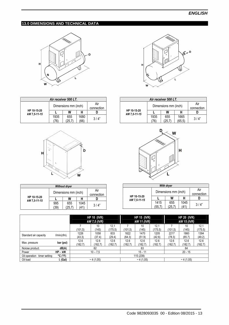
13.0 DIMENSIONS AND TECHNICAL DATA
Air receiver 500 LT. Air receiver 500 LT.
HP 10-15-20 kW 7,5-11-15
Dimensions mm (inch) Air
connection
HP 10-15-20 kW 7,5-11-15
Dimensions mm (inch) Air
connection
L W H D L W H D
1935 (76)
655 (25,7)
1680 (66)
3 / 4” 1935
(76) 655
(25,7) 1665 (65,5)
3 / 4”
Without dryer
HP 10-15-20 kW 7,5-11-15
Dimensions mm (inch) Air
connection
L W H D
995 (39)
655 (25,7)
1045 (41)
3 / 4”
HP 10 (IVR)
kW 7,5 (IVR) HP 15 (IVR)
kW 11 (IVR)
HP 20 (IVR)
kW 15 (IVR)
7 (101,5)
10 (145)
12,1 (175.5)
7 (101,5)
10 (145)
12,1 (175.5)
7 (101,5)
10 (145)
12,1 (175.5)
Standard air capacity l/min(cfm). 1226 (43.3)
1058 (37.4)
833 (29.4)
1822 (64.3)
1470 (51.9)
1205 (42.6)
2217 (78.3)
1860 (65.7)
1394 (49.2)
Max. pressure bar (psi) 12.6
(182.7) 12.6
(182.7) 12.6
(182.7) 12.6
(182.7) 12.6
(182.7) 12.6
(182.7) 12.6
(182.7) 12.6
(182.7) 12.6
(182.7)
Noiose product. dB(A) 62 63 64
Power HP - kW 10 – 7,5 15 - 11 20 - 15
Oil operation timer setting °C (°F) 115 (239)
Oil load l. (Gal) ~ 4 (1,05) ~ 4 (1,05) ~ 4 (1,05)
With dryer
HP 10-15-20 kW 7,5-11-15
Dimensions mm (inch) Air
connection
L W H D
1415 (55,7)
655 (25,7)
1045 (41)
3 / 4”
ENGLISH
14 - Edition 08/2015 Code 9828093035 00 -
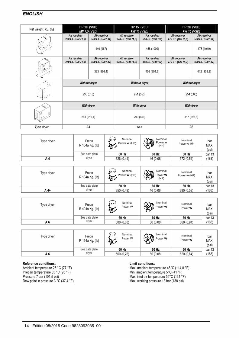
Net weight Kg. (lb) HP 10 (VSD)
kW 7,5 (VSD) HP 15 (VSD)
kW 11 (VSD)
HP 20 (VSD)
kW 15 (VSD)
Air receiver 270 LT. (Gal 71,3)
Air receiver 500 LT. (Gal 132)
Air receiver 270 LT. (Gal 71,3)
Air receiver 500 LT. (Gal 132)
Air receiver 270 LT. (Gal 71,3)
Air receiver 500 LT. (Gal 132)
440 (967) 458 (1009) 476 (1049)
Air receiver 270 LT. (Gal 71,3)
Air receiver 500 LT. (Gal 132)
Air receiver 270 LT. (Gal 71,3)
Air receiver 500 LT. (Gal 132)
Air receiver 270 LT. (Gal 71,3)
Air receiver 500 LT. (Gal 132)
393 (866,4) 409 (901,6) 412 (908,3)
Without dryer Without dryer Without dryer
235 (518) 251 (553) 254 (600)
With dryer With dryer With dryer
281 (619,4) 299 (659) 317 (698,8)
Type dryer A4 A4+ A6
Type dryer
Freon
R 134a Kg. (lb)
Nominal
Power w (HP)
bar
MAX.
(psi) See data plate
dryer 60 Hz 60 Hz 60 Hz bar 13
(188) A 4 326 (0,44) 46 (0,06) 372 (0,51)
Type dryer
Freon
R 134a Kg. (lb)
Nominal
Power w (HP)
bar
MAX.
(psi) See data plate
dryer 60 Hz 60 Hz 60 Hz bar 13
(188) A 4+ 350 (0,48) 46 (0,06) 380 (0,52)
Type dryer
Freon
R 404a Kg. (lb)
Nominal
Power w
bar
MAX.
(psi) See data plate
dryer 60 Hz 60 Hz 60 Hz bar 13
(188) A 6 608 (0,83) 60 (0,08) 668 (0,91)
Type dryer
Freon
R 134a Kg. (lb)
Nominal
Power w
bar
MAX.
(psi) See data plate
dryer 60 Hz 60 Hz 60 Hz bar 13
(188) A 6 560 (0,76) 60 (0,08) 620 (0,84)
Reference conditions: Ambient temperature 25 °C (77 °F) Inlet air temperature 35 °C (95 °F) Pressure 7 bar (101,5 psi) Dew point in pressure 3 °C (37,4 °F)
Limit conditions: Max. ambient temperature 46°C (114,8 °F) Min. ambient temperature 5°C (41 °F) Max. inlet air temperature 55°C (131 °F) Max. working pressure 13 bar (188 psi)
Nominal
Power w (HP)
Nominal Power w
(HP)
Nominal
Power w (HP)
Nominal
Power w (HP)
Nominal
Power w
Nominal
Power w
Nominal
Power w
Nominal
Power w
ENGLISH
Code 9828093035 00 - Edition 08/2015 - 15
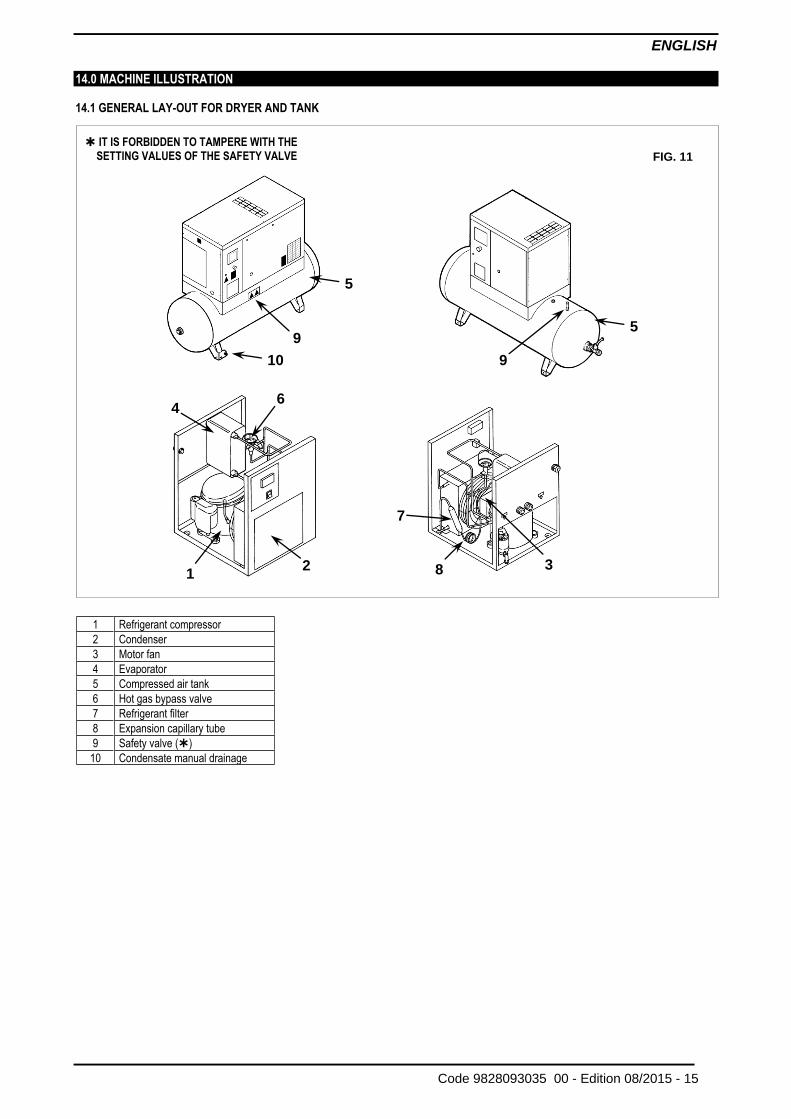
14.0 MACHINE ILLUSTRATION 14.1 GENERAL LAY-OUT FOR DRYER AND TANK
FIG. 11
9
5
1 2
6 4
7
8 3
IT IS FORBIDDEN TO TAMPERE WITH THE
SETTING VALUES OF THE SAFETY VALVE
1 Refrigerant compressor
2 Condenser
3 Motor fan
4 Evaporator 5 Compressed air tank
6 Hot gas bypass valve
7 Refrigerant filter
8 Expansion capillary tube
9 Safety valve ()
10 Condensate manual drainage
5
10
9
ENGLISH
16 - Edition 08/2015 Code 9828093035 00 -
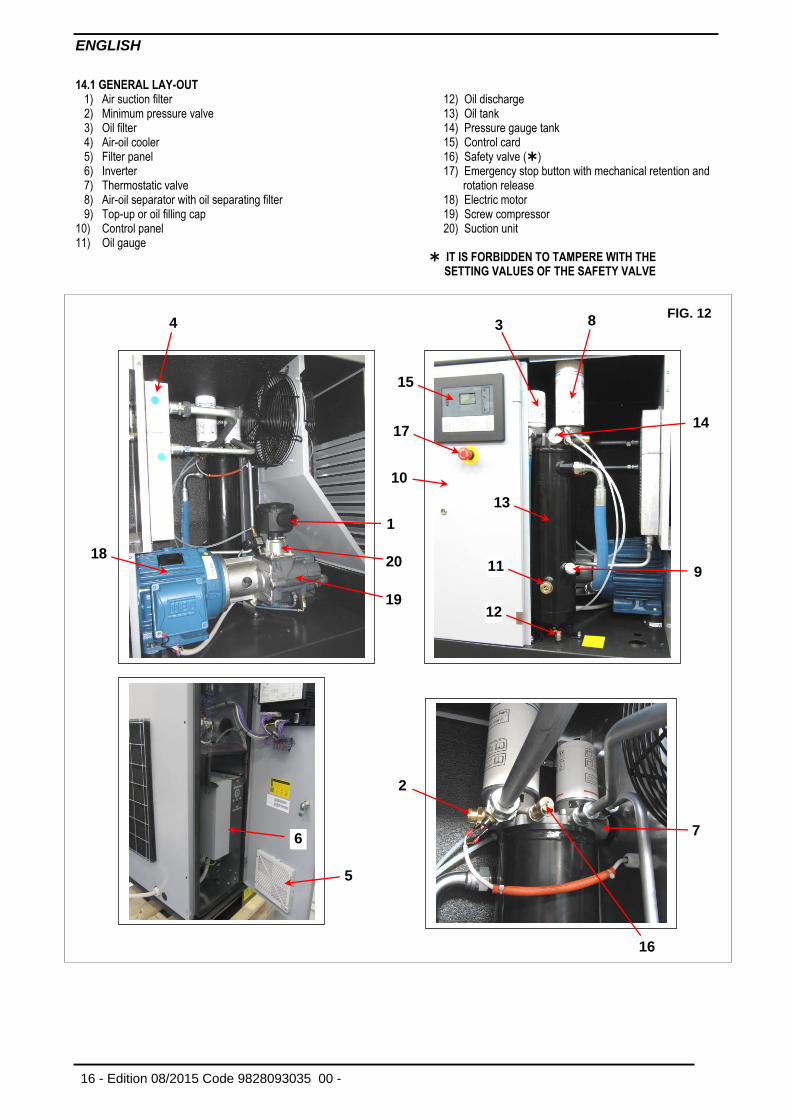
14.1 GENERAL LAY-OUT 1) Air suction filter 2) Minimum pressure valve 3) Oil filter 4) Air-oil cooler 5) Filter panel 6) Inverter 7) Thermostatic valve 8) Air-oil separator with oil separating filter 9) Top-up or oil filling cap 10) Control panel 11) Oil gauge
12) Oil discharge 13) Oil tank 14) Pressure gauge tank 15) Control card 16) Safety valve () 17) Emergency stop button with mechanical retention and
rotation release 18) Electric motor 19) Screw compressor 20) Suction unit IT IS FORBIDDEN TO TAMPERE WITH THE
SETTING VALUES OF THE SAFETY VALVE
FIG. 12
1
2
3
4
7
8
9
10
11
12
13
14
15
16
17
18
19
20
5
6
ENGLISH
Code 9828093035 00 - Edition 08/2015 - 17
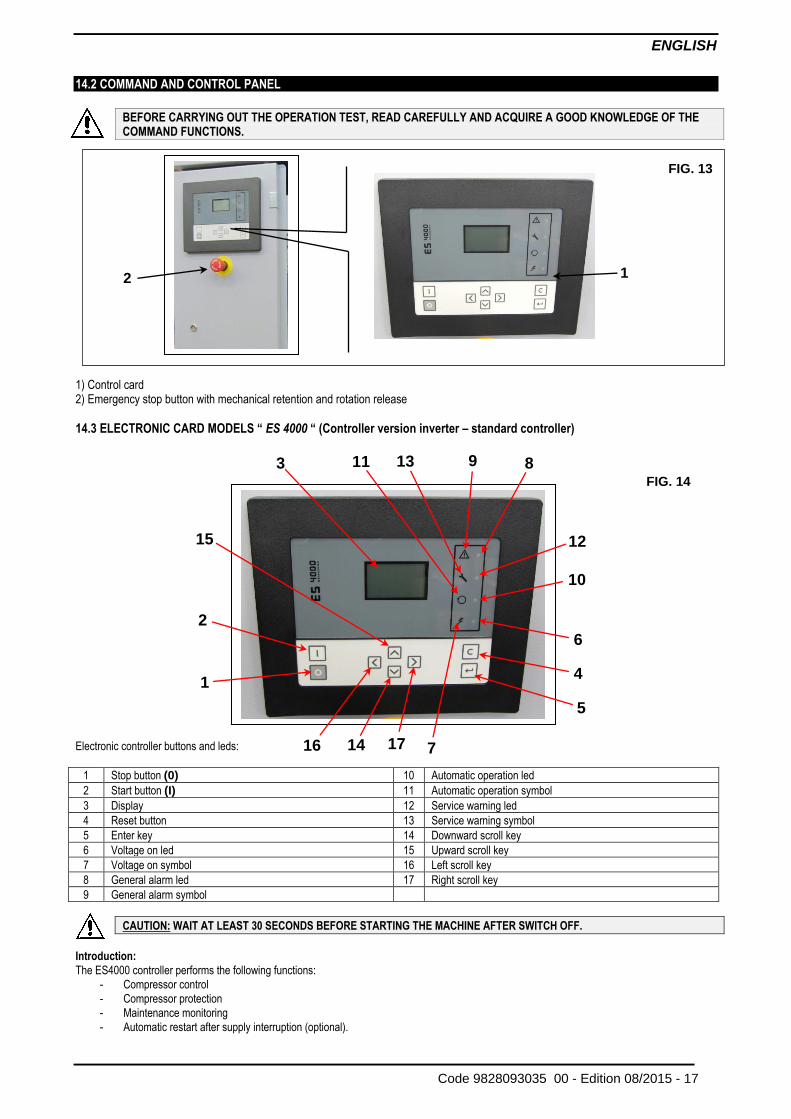
14.2 COMMAND AND CONTROL PANEL
BEFORE CARRYING OUT THE OPERATION TEST, READ CAREFULLY AND ACQUIRE A GOOD KNOWLEDGE OF THE COMMAND FUNCTIONS.
1) Control card 2) Emergency stop button with mechanical retention and rotation release
14.3 ELECTRONIC CARD MODELS “ ES 4000 “ (Controller version inverter – standard controller)
Electronic controller buttons and leds:
1 Stop button (0) 10 Automatic operation led
2 Start button (I) 11 Automatic operation symbol
3 Display 12 Service warning led
4 Reset button 13 Service warning symbol
5 Enter key 14 Downward scroll key
6 Voltage on led 15 Upward scroll key
7 Voltage on symbol 16 Left scroll key
8 General alarm led 17 Right scroll key
9 General alarm symbol
CAUTION: WAIT AT LEAST 30 SECONDS BEFORE STARTING THE MACHINE AFTER SWITCH OFF.
Introduction:
The ES4000 controller performs the following functions:
- Compressor control
- Compressor protection
- Maintenance monitoring
- Automatic restart after supply interruption (optional).
FIG. 13
2
1
FIG. 14
9 13 11
7
4
5
8
12
10
6
2
1
3
15
17 16 14
ENGLISH
18 - Edition 08/2015 Code 9828093035 00 -
Automatic control of the compressor
The controller maintains the outlet pressure within defined limits, commanding the load and unload operations of the compressor. Various
parameters are considered, among them are: the unload pressure, the load pressure, the minimum stop time and the maximum number of motor
starts.
Compressor protection
Shutdown
If element outlet temperature of the element exceeds the programmed shut down level, the compressor will be stopped. This will be indicated on
the display (3). The compressor will be stopped also in case of inverter alarm. Before remedying, consult the safety precautions.
Shut down warning:
A shut-down warning level is a programmable level below the shut-down level. If one of the measured values exceeds the value of the alarm threshold, this will be indicated before reaching the threshold stop for failure. Service warning:
If the service timer exceeds the programmed value, this will be indicated on the display (3) to warn the operator to perform the required service
operations
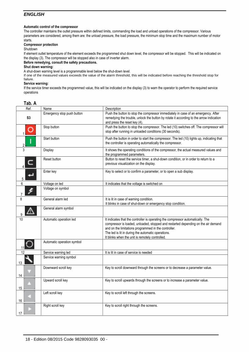
Tab. A
Ref. Name Description
S3
Emergency stop push button Push the button to stop the compressor immediately in case of an emergency. After
remedying the trouble, unlock the button by rotate it according to the arrow indication
and press the reset key (4).
1
Stop button Push the button to stop the compressor. The led (10) switches off. The compressor will
stop after running in unloaded conditions (30 seconds).
2
Start button Push the button in order to start the compressor. The led (10) lights up, indicating that
the controller is operating automatically the compressor.
3 Display It shows the operating conditions of the compressor, the actual measured values and
the programmed parameters.
4
Reset button Button to reset the service timer, a shut-down condition, or in order to return to a
previous visualization on the display.
5
Enter key Key to select or to confirm a parameter, or to open a sub display.
6 Voltage on led It indicates that the voltage is switched on
7
Voltage on symbol
8 General alarm led It is lit in case of warning condition.
It blinks in case of shut-down or emergency stop condition.
9
General alarm symbol
10 Automatic operation led It indicates that the controller is operating the compressor automatically. The
compressor is loaded, unloaded, stopped and restarted depending on the air demand
and on the limitations programmed in the controller.
The led is lit in during the automatic operations.
It blinks when the unit is remotely controlled.
11
Automatic operation symbol
12 Service warning led It is lit in case of service is needed
13
Service warning symbol
14
Downward scroll key Key to scroll downward through the screens or to decrease a parameter value.
15
Upward scroll key Key to scroll upwards through the screens or to increase a parameter value.
16
Left scroll key Key to scroll left through the screens.
17
Right scroll key Key to scroll right through the screens.
ENGLISH
Code 9828093035 00 - Edition 08/2015 - 19
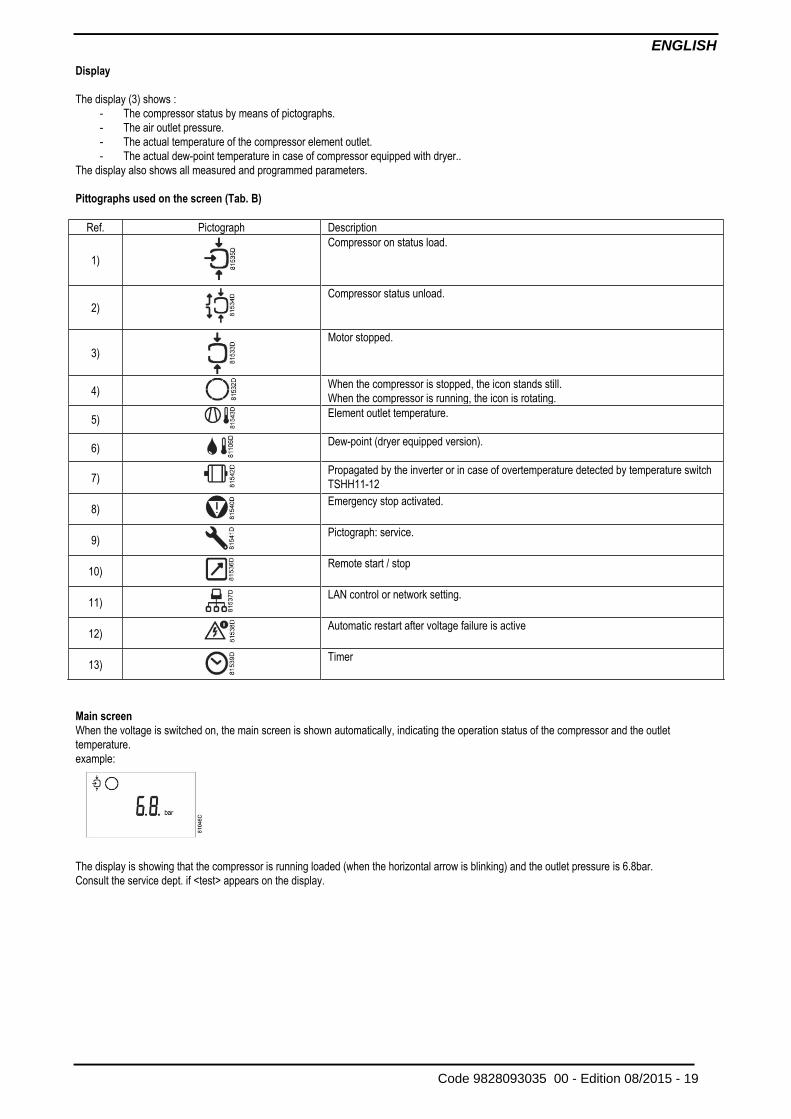
Display
The display (3) shows :
- The compressor status by means of pictographs.
- The air outlet pressure.
- The actual temperature of the compressor element outlet.
- The actual dew-point temperature in case of compressor equipped with dryer..
The display also shows all measured and programmed parameters.
Pittographs used on the screen (Tab. B)
Ref. Pictograph Description
1)
Compressor on status load.
2)
Compressor status unload.
3)
Motor stopped.
4)
When the compressor is stopped, the icon stands still.
When the compressor is running, the icon is rotating.
5)
Element outlet temperature.
6)
Dew-point (dryer equipped version).
7)
Propagated by the inverter or in case of overtemperature detected by temperature switch
TSHH11-12
8)
Emergency stop activated.
9)
Pictograph: service.
10)
Remote start / stop
11)
LAN control or network setting.
12)
Automatic restart after voltage failure is active
13)
Timer
Main screen
When the voltage is switched on, the main screen is shown automatically, indicating the operation status of the compressor and the outlet
temperature.
example:
The display is showing that the compressor is running loaded (when the horizontal arrow is blinking) and the outlet pressure is 6.8bar.
Consult the service dept. if <test> appears on the display.
ENGLISH
20 - Edition 08/2015 Code 9828093035 00 -
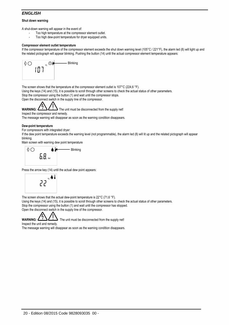
Shut down warning
A shut-down warning will appear in the event of:
- Too high temperature at the compressor element outlet.
- Too high dew-point temperature for dryer equipped units.
Compressor element outlet temperature
If the compressor temperature of the compressor element exceeds the shut down warning level (105°C / 221°F), the alarm led (8) will light up and
the related pictograph will appear blinking. Pushing the button (14) until the actual compressor element temperature appears:
The screen shows that the temperature at the compressor element outlet is 107°C (224,6 °F).
Using the keys (14) and (15), it is possible to scroll through other screens to check the actual status of other parameters.
Stop the compressor using the button (1) and wait until the compressor stops.
Open the disconnect switch in the supply line of the compressor.
WARNING: The unit must be disconnected from the supply net!
Inspect the compressor and remedy.
The message warning will disappear as soon as the warning condition disappears.
Dew-point temperature
For compressors with integrated dryer:
If the dew point temperature exceeds the warning level (not programmable), the alarm led (8) will lit up and the related pictograph will appear
blinking.
Main screen with warning dew point temperature
Press the arrow key (14) until the actual dew point appears:
The screen shows that the actual dew-point temperature is 22°C (71,6 °F).
Using the keys (14) and (15), it is possible to scroll through other screens to check the actual status of other parameters.
Stop the compressor using the button (1) and wait until the compressor has stopped.
Open the disconnect switch in the supply line of the compressor.
WARNING: The unit must be disconnected from the supply net!
Inspect the unit and remedy.
The message warning will disappear as soon as the warning condition disappears.
Blinking
Blinking
ENGLISH
Code 9828093035 00 - Edition 08/2015 - 21
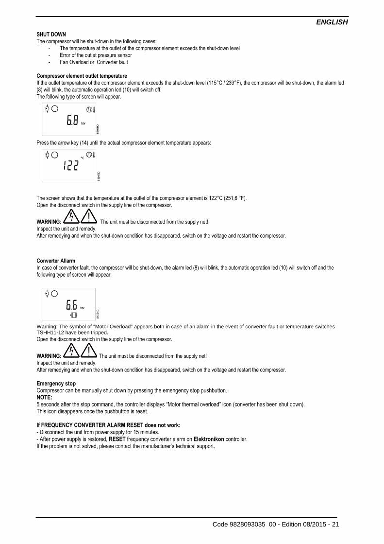
SHUT DOWN
The compressor will be shut-down in the following cases:
- The temperature at the outlet of the compressor element exceeds the shut-down level
- Error of the outlet pressure sensor
- Fan Overload or Converter fault Compressor element outlet temperature
If the outlet temperature of the compressor element exceeds the shut-down level (115°C / 239°F), the compressor will be shut-down, the alarm led
(8) will blink, the automatic operation led (10) will switch off.
The following type of screen will appear.
Press the arrow key (14) until the actual compressor element temperature appears:
The screen shows that the temperature at the outlet of the compressor element is 122°C (251,6 °F).
Open the disconnect switch in the supply line of the compressor.
WARNING: The unit must be disconnected from the supply net!
Inspect the unit and remedy.
After remedying and when the shut-down condition has disappeared, switch on the voltage and restart the compressor.
Converter Allarm
In case of converter fault, the compressor will be shut-down, the alarm led (8) will blink, the automatic operation led (10) will switch off and the
following type of screen will appear:
Warning: The symbol of "Motor Overload" appears both in case of an alarm in the event of converter fault or temperature switches TSHH11-12 have been tripped.
Open the disconnect switch in the supply line of the compressor.
WARNING: The unit must be disconnected from the supply net!
Inspect the unit and remedy.
After remedying and when the shut-down condition has disappeared, switch on the voltage and restart the compressor.
Emergency stop Compressor can be manually shut down by pressing the emengency stop pushbutton. NOTE: 5 seconds after the stop command, the controller displays “Motor thermal overload” icon (converter has been shut down). This icon disappears once the pushbutton is reset.
If FREQUENCY CONVERTER ALARM RESET does not work: - Disconnect the unit from power supply for 15 minutes. - After power supply is restored, RESET frequency converter alarm on Elektronikon controller. If the problem is not solved, please contact the manufacturer’s technical support.
ENGLISH
22 - Edition 08/2015 Code 9828093035 00 -
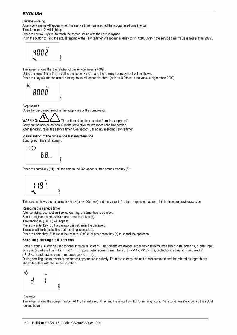
Service warning
A service warning will appear when the service timer has reached the programmed time interval.
The alarm led (12) will light up.
Press the arrow key (14) to reach the screen <d06> with the service symbol.
Push the button (5) and the actual reading of the service timer will appear in <hrs> (or in <x1000hrs> if the service timer value is higher than 9999).
The screen shows that the reading of the service timer is 4002h.
Using the keys (14) or (15), scroll to the screen <d.01> and the running hours symbol will be shown.
Press the key (5) and the actual running hours will appear in <hrs> (or in <x1000hrs> if the value is higher than 9999).
Stop the unit.
Open the disconnect switch in the supply line of the compressor.
WARNING: The unit must be disconnected from the supply net!
Carry out the service actions. See the preventive maintenance schedule section.
After servicing, reset the service timer. See section Calling up/ resetting service timer.
Visualization of the time since last maintenance
Starting from the main screen:
Press the scroll key (14) until the screen <d.06> appears, then press enter key (5):
This screen shows the unit used is <hrs> (or <x1000 hrs>) and the value 1191: the compressor has run 1191 h since the previous service.
Resetting the service timer
After servicing, see section Service warning, the timer has to be reset:
Scroll to register screen <d.06> and press enter key (5).
The reading (e.g. 4000) will appear.
Press the enter key (5). If a password is set, enter the password.
The icon will flash (indicating that resetting is possible).
Press the enter key (5) to reset the timer to <0.000> or press reset key (4) to cancel the operation.
Scro l l ing th rough a l l screens
Scroll buttons (14) can be used to scroll through all screens. The screens are divided into register screens, measured data screens, digital input
screens (numbered as <d.in>, <d.1>, ...), parameter screens (numbered as <P.1>, <P.2>, ...), protections screens (numbered as
<Pr.2>,...) and test screens (numbered as <t.1>,...). During scrolling, the numbers of the screens appear consecutively. For most screens, the unit of measurement and the related pictograph are
shown together with the screen number.
Example
The screen shows the screen number <d.1>, the unit used <hrs> and the related symbol for running hours. Press Enter key (5) to call up the actual
running hours.
ENGLISH
Code 9828093035 00 - Edition 08/2015 - 23
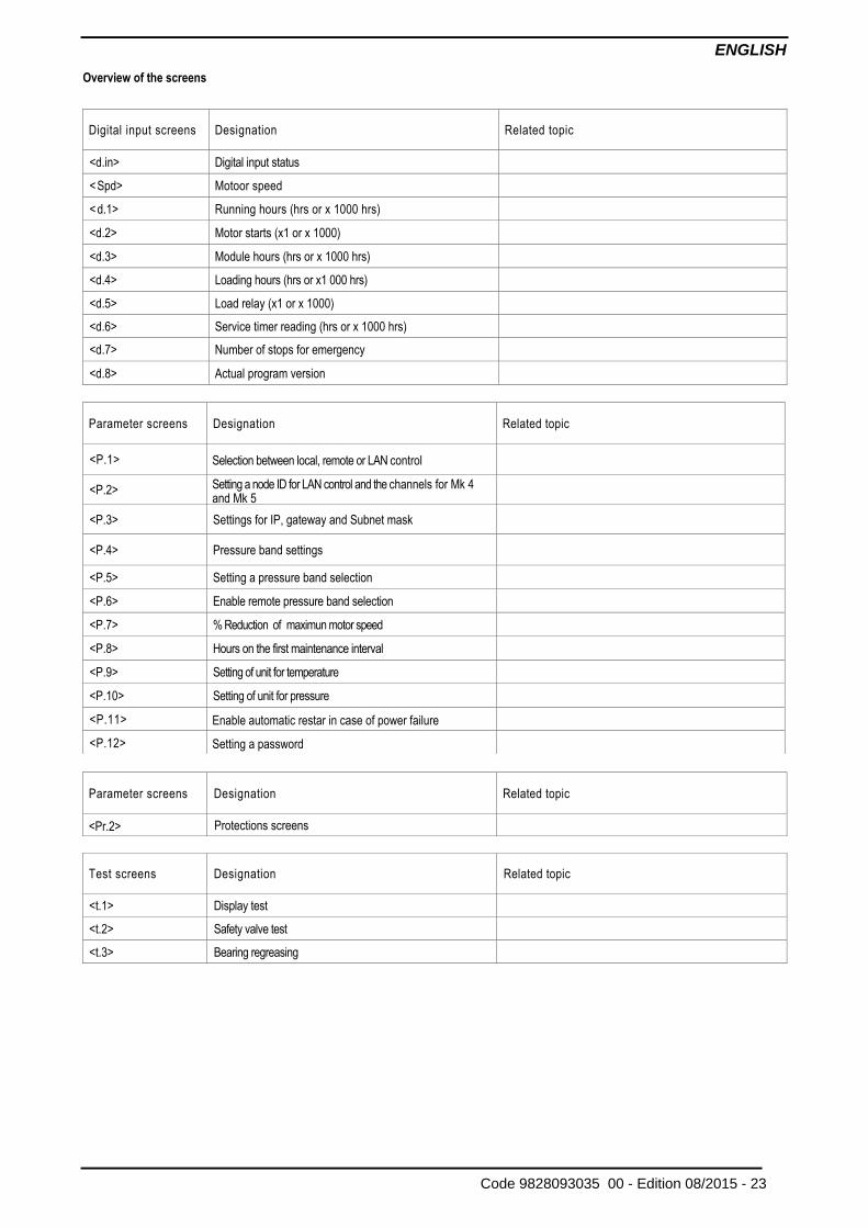
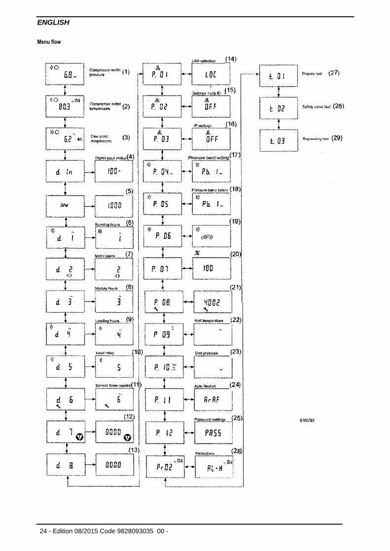
Overview of the screens
Digital input screens Designation Related topic
<d.in> Digital input status
<Spd> Motoor speed
<d.1> Running hours (hrs or x 1000 hrs)
<d.2> Motor starts (x1 or x 1000)
<d.3> Module hours (hrs or x 1000 hrs)
<d.4> Loading hours (hrs or x1 000 hrs)
<d.5> Load relay (x1 or x 1000)
<d.6> Service timer reading (hrs or x 1000 hrs)
<d.7> Number of stops for emergency
<d.8> Actual program version
Parameter screens Designation Related topic
<P.1> Selection between local, remote or LAN control
<P.2> Setting a node ID for LAN control and the channels for Mk 4 and Mk 5
<P.3> Settings for IP, gateway and Subnet mask
<P.4> Pressure band settings
<P.5> Setting a pressure band selection
<P.6> Enable remote pressure band selection
<P.7> % Reduction of maximun motor speed
<P.8> Hours on the first maintenance interval
<P.9> Setting of unit for temperature
<P.10> Setting of unit for pressure
<P.11> Enable automatic restar in case of power failure
<P.12> Setting a password
Parameter screens Designation Related topic
<Pr.2> Protections screens
Test screens Designation Related topic
<t.1> Display test
<t.2> Safety valve test
<t.3> Bearing regreasing
ENGLISH
24 - Edition 08/2015 Code 9828093035 00 -
Menu flow
ENGLISH
Code 9828093035 00 - Edition 08/2015 - 25
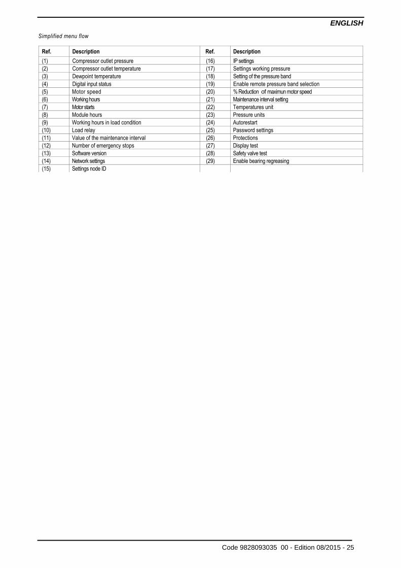
Simplified menu flow
Ref. Description Ref. Description
(1) Compressor outlet pressure (16) IP settings
(2) Compressor outlet temperature (17) Settings working pressure
(3) Dewpoint temperature (18) Setting of the pressure band
(4) Digital input status (19) Enable remote pressure band selection
(5) Motor speed (20) % Reduction of maximun motor speed
(6) Working hours (21) Maintenance interval setting
(7) Motor starts (22) Temperatures unit
(8) Module hours (23) Pressure units
(9) Working hours in load condition (24) Autorestart
(10) Load relay (25) Password settings
(11) Value of the maintenance interval (26) Protections
(12) Number of emergency stops (27) Display test
(13) Software version (28) Safety valve test
(14) Network settings (29) Enable bearing regreasing
(15) Settings node ID
ENGLISH
26 - Edition 08/2015 Code 9828093035 00 -
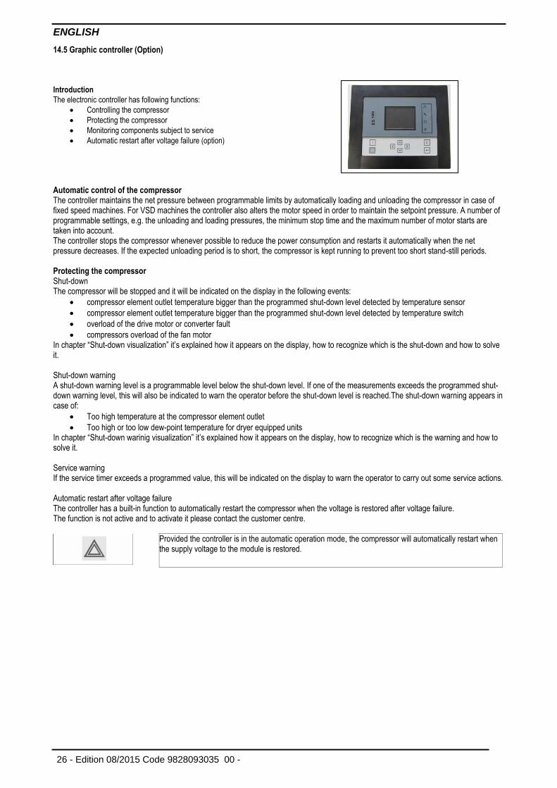
14.5 Graphic controller (Option)
Introduction
The electronic controller has following functions:
Controlling the compressor
Protecting the compressor
Monitoring components subject to service
Automatic restart after voltage failure (option)
Automatic control of the compressor The controller maintains the net pressure between programmable limits by automatically loading and unloading the compressor in case of fixed speed machines. For VSD machines the controller also alters the motor speed in order to maintain the setpoint pressure. A number of programmable settings, e.g. the unloading and loading pressures, the minimum stop time and the maximum number of motor starts are taken into account. The controller stops the compressor whenever possible to reduce the power consumption and restarts it automatically when the net pressure decreases. If the expected unloading period is to short, the compressor is kept running to prevent too short stand-still periods. Protecting the compressor
Shut-down The compressor will be stopped and it will be indicated on the display in the following events:
compressor element outlet temperature bigger than the programmed shut-down level detected by temperature sensor
compressor element outlet temperature bigger than the programmed shut-down level detected by temperature switch
overload of the drive motor or converter fault
compressors overload of the fan motor In chapter “Shut-down visualization” it’s explained how it appears on the display, how to recognize which is the shut-down and how to solve it.
Shut-down warning A shut-down warning level is a programmable level below the shut-down level. If one of the measurements exceeds the programmed shut-down warning level, this will also be indicated to warn the operator before the shut-down level is reached.The shut-down warning appears in case of:
Too high temperature at the compressor element outlet
Too high or too low dew-point temperature for dryer equipped units In chapter “Shut-down warinig visualization” it’s explained how it appears on the display, how to recognize which is the warning and how to solve it.
Service warning If the service timer exceeds a programmed value, this will be indicated on the display to warn the operator to carry out some service actions.
Automatic restart after voltage failure The controller has a built-in function to automatically restart the compressor when the voltage is restored after voltage failure. The function is not active and to activate it please contact the customer centre.
Provided the controller is in the automatic operation mode, the compressor will automatically restart when the supply voltage to the module is restored.
ENGLISH
Code 9828093035 00 - Edition 08/2015 - 27
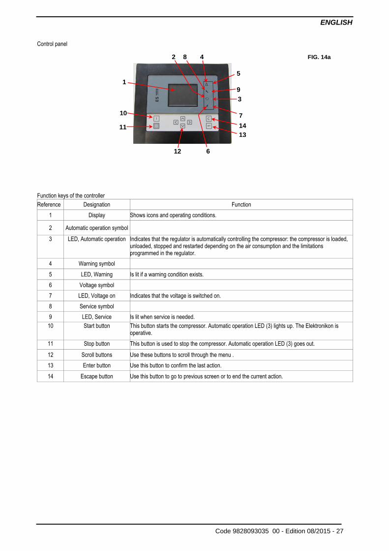
Control panel
Function keys of the controller
Reference Designation Function
1 Display Shows icons and operating conditions.
2 Automatic operation symbol
3 LED, Automatic operation Indicates that the regulator is automatically controlling the compressor: the compressor is loaded, unloaded, stopped and restarted depending on the air consumption and the limitations programmed in the regulator.
4 Warning symbol
5 LED, Warning Is lit if a warning condition exists.
6 Voltage symbol
7 LED, Voltage on Indicates that the voltage is switched on.
8 Service symbol
9 LED, Service Is lit when service is needed.
10 Start button This button starts the compressor. Automatic operation LED (3) lights up. The Elektronikon is operative.
11 Stop button This button is used to stop the compressor. Automatic operation LED (3) goes out.
12 Scroll buttons Use these buttons to scroll through the menu .
13 Enter button Use this button to confirm the last action.
14 Escape button Use this button to go to previous screen or to end the current action.
FIG. 14a 2
6
5
9
3
7
14
13
4 8
12
1
10
11
ENGLISH
28 - Edition 08/2015 Code 9828093035 00 -
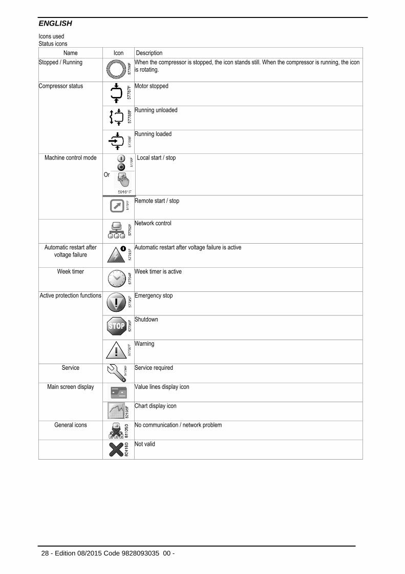
Icons used Status icons
Name Icon Description
Stopped / Running
When the compressor is stopped, the icon stands still. When the compressor is running, the icon is rotating.
Compressor status
Motor stopped
Running unloaded
Running loaded
Machine control mode
Or
Local start / stop
Remote start / stop
Network control
Automatic restart after voltage failure
Automatic restart after voltage failure is active
Week timer
Week timer is active
Active protection functions
Emergency stop
Shutdown
Warning
Service
Service required
Main screen display
Value lines display icon
Chart display icon
General icons
No communication / network problem
Not valid
ENGLISH
Code 9828093035 00 - Edition 08/2015 - 29
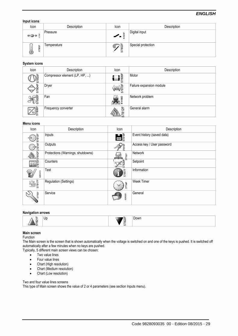
Input icons
Icon Description Icon Description
Pressure
Digital input
Temperature
Special protection
System icons
Menu icons
Icon Description Icon Description
Inputs
Event history (saved data)
Outputs
Access key / User password
Protections (Warnings, shutdowns)
Network
Counters
Setpoint
Test
Information
Regulation (Settings)
Week Timer
Service
General
Navigation arrows
Main screen Function The Main screen is the screen that is shown automatically when the voltage is switched on and one of the keys is pushed. It is switched off automatically after a few minutes when no keys are pushed. Typically, 5 different main screen views can be chosen:
Two value lines
Four value lines
Chart (High resolution)
Chart (Medium resolution)
Chart (Low resolution)
Two and four value lines screens This type of Main screen shows the value of 2 or 4 parameters (see section Inputs menu).
Icon Description Icon Description
Compressor element (LP, HP, ...)
Motor
Dryer
Failure expansion module
Fan
Network problem
Frequency converter
General alarm
Up
Down
ENGLISH
30 - Edition 08/2015 Code 9828093035 00 -
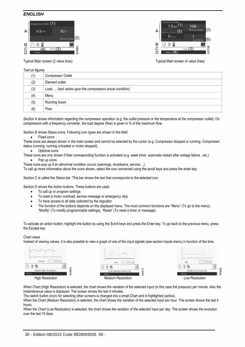
Typical Main screen (2 value lines) Typical Main screen (4 value lines) Text on figures
(1) Compressor Outlet
(2) Element outlet
(3) Load, ... (text varies upon the compressors actual condition)
(4) Menu
(5) Running hours
(6) Flow
Section A shows information regarding the compressor operation (e.g. the outlet pressure or the temperature at the compressor outlet). On compressors with a frequency converter, the load degree (flow) is given in % of the maximum flow. Section B shows Status icons. Following icon types are shown in this field:
Fixed icons These icons are always shown in the main screen and cannot be selected by the cursor (e.g. Compressor stopped or running, Compressor status (running, running unloaded or motor stopped).
Optional icons These icons are only shown if their corresponding function is activated (e.g. week timer, automatic restart after voltage failure , etc.)
Pop up icons These icons pop up if an abnormal condition occurs (warnings, shutdowns, service,...) To call up more information about the icons shown, select the icon concerned using the scroll keys and press the enter key. Section C is called the Status bar. This bar shows the text that corresponds to the selected icon. Section D shows the Action buttons. These buttons are used:
To call up or program settings
To reset a motor overload, service message or emergency stop
To have access to all data collected by the regulator
The function of the buttons depends on the displayed menu. The most common functions are “Menu” (To go to the menu), “Modify” (To modify programmable settings), “Reset” (To reset a timer or message)
To activate an action button, highlight the button by using the Scroll keys and press the Enter key. To go back to the previous menu, press the Escape key. Chart views Instead of viewing values, it is also possible to view a graph of one of the input signals (see section Inputs menu) in function of the time.
High Resolution Medium Resolution Low Resolution When Chart (High Resolution) is selected, the chart shows the variation of the selected input (in this case the pressure) per minute. Also the instantaneous value is displayed. The screen shows the last 4 minutes. The switch button (icon) for selecting other screens is changed into a small Chart and is highlighted (active). When the Chart (Medium Resolution) is selected, the chart shows the variation of the selected input per hour. The screen shows the last 4 hours. When the Chart (Low Resolution) is selected, the chart shows the variation of the selected input per day. The screen shows the evolution over the last 10 days.
ENGLISH
Code 9828093035 00 - Edition 08/2015 - 31
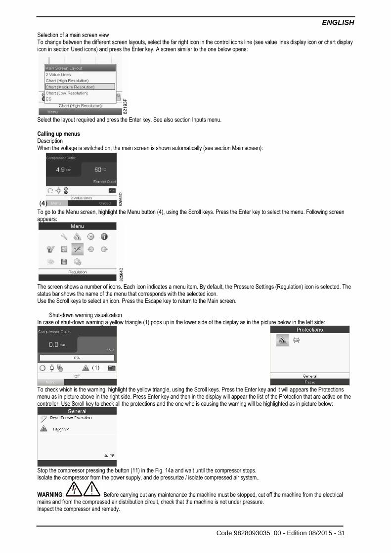
Selection of a main screen view To change between the different screen layouts, select the far right icon in the control icons line (see value lines display icon or chart display icon in section Used icons) and press the Enter key. A screen similar to the one below opens:
Select the layout required and press the Enter key. See also section Inputs menu. Calling up menus Description When the voltage is switched on, the main screen is shown automatically (see section Main screen):
To go to the Menu screen, highlight the Menu button (4), using the Scroll keys. Press the Enter key to select the menu. Following screen appears:
The screen shows a number of icons. Each icon indicates a menu item. By default, the Pressure Settings (Regulation) icon is selected. The status bar shows the name of the menu that corresponds with the selected icon. Use the Scroll keys to select an icon. Press the Escape key to return to the Main screen.
Shut-down warning visualization In case of shut-down warning a yellow triangle (1) pops up in the lower side of the display as in the picture below in the left side:
To check which is the warning, highlight the yellow triangle, using the Scroll keys. Press the Enter key and it will appears the Protections menu as in picture above in the right side. Press Enter key and then in the display will appear the list of the Protection that are active on the controller. Use Scroll key to check all the protections and the one who is causing the warning will be highlighted as in picture below:
Stop the compressor pressing the button (11) in the Fig. 14a and wait until the compressor stops. Isolate the compressor from the power supply, and de pressurize / isolate compressed air system..
WARNING: Before carrying out any maintenance the machine must be stopped, cut off the machine from the electrical mains and from the compressed air distribution circuit, check that the machine is not under pressure. Inspect the compressor and remedy.
ENGLISH
32 - Edition 08/2015 Code 9828093035 00 -
The message warning will disappear as soon as the warning condition disappears.
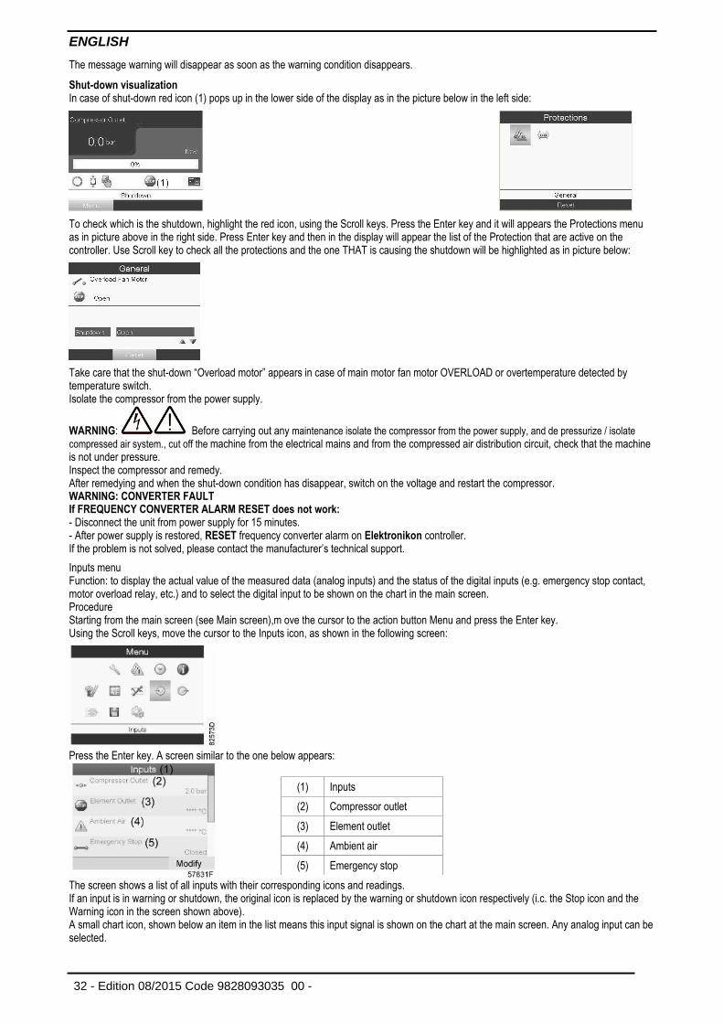
Shut-down visualization In case of shut-down red icon (1) pops up in the lower side of the display as in the picture below in the left side:
To check which is the shutdown, highlight the red icon, using the Scroll keys. Press the Enter key and it will appears the Protections menu as in picture above in the right side. Press Enter key and then in the display will appear the list of the Protection that are active on the controller. Use Scroll key to check all the protections and the one THAT is causing the shutdown will be highlighted as in picture below:
Take care that the shut-down “Overload motor” appears in case of main motor fan motor OVERLOAD or overtemperature detected by temperature switch. Isolate the compressor from the power supply.
WARNING: Before carrying out any maintenance isolate the compressor from the power supply, and de pressurize / isolate
compressed air system., cut off the machine from the electrical mains and from the compressed air distribution circuit, check that the machine is not under pressure. Inspect the compressor and remedy. After remedying and when the shut-down condition has disappear, switch on the voltage and restart the compressor. WARNING: CONVERTER FAULT If FREQUENCY CONVERTER ALARM RESET does not work: - Disconnect the unit from power supply for 15 minutes. - After power supply is restored, RESET frequency converter alarm on Elektronikon controller. If the problem is not solved, please contact the manufacturer’s technical support.
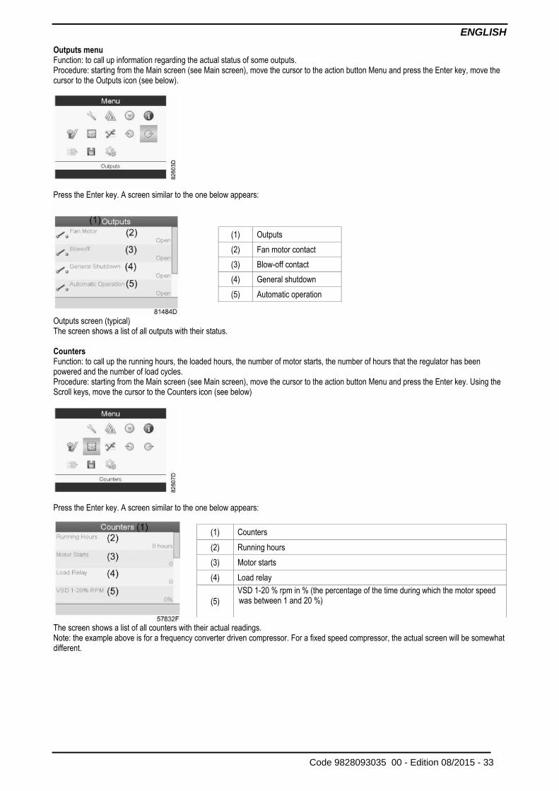
Inputs menu Function: to display the actual value of the measured data (analog inputs) and the status of the digital inputs (e.g. emergency stop contact, motor overload relay, etc.) and to select the digital input to be shown on the chart in the main screen. Procedure Starting from the main screen (see Main screen),m ove the cursor to the action button Menu and press the Enter key. Using the Scroll keys, move the cursor to the Inputs icon, as shown in the following screen:
Press the Enter key. A screen similar to the one below appears:
The screen shows a list of all inputs with their corresponding icons and readings. If an input is in warning or shutdown, the original icon is replaced by the warning or shutdown icon respectively (i.c. the Stop icon and the Warning icon in the screen shown above). A small chart icon, shown below an item in the list means this input signal is shown on the chart at the main screen. Any analog input can be selected.
(1) Inputs
(2) Compressor outlet
(3) Element outlet
(4) Ambient air
(5) Emergency stop
ENGLISH
Code 9828093035 00 - Edition 08/2015 - 33
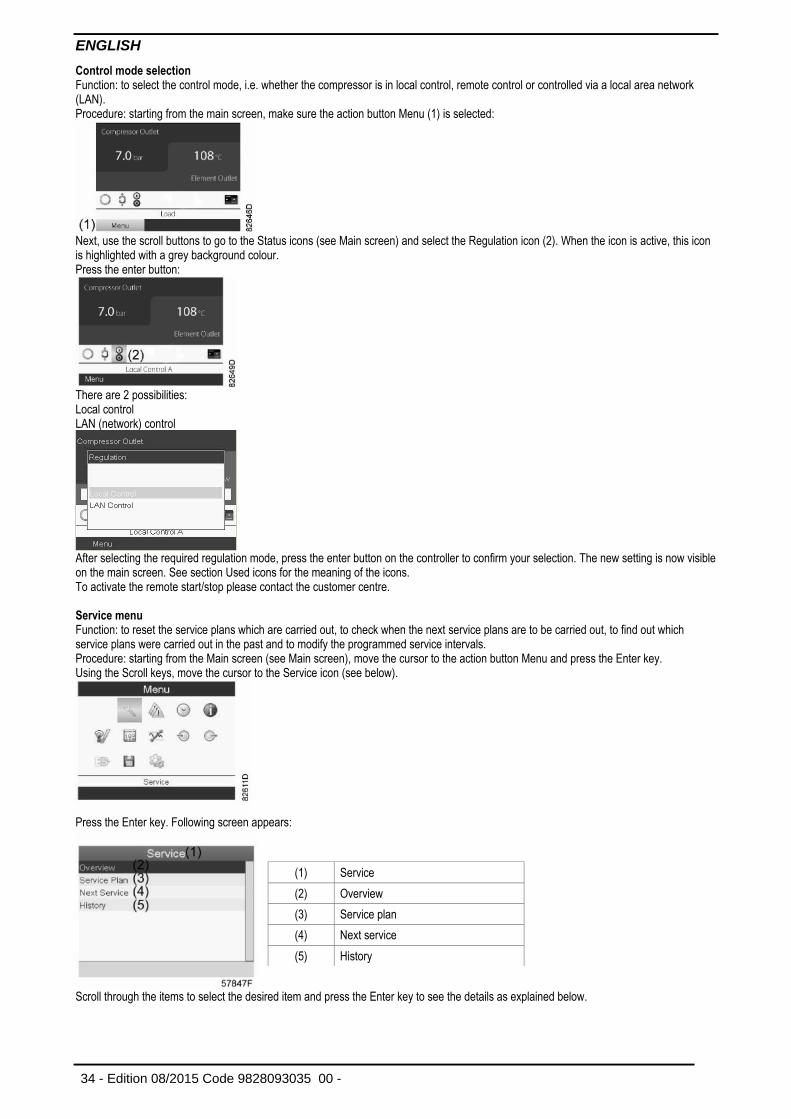
Outputs menu Function: to call up information regarding the actual status of some outputs. Procedure: starting from the Main screen (see Main screen), move the cursor to the action button Menu and press the Enter key, move the cursor to the Outputs icon (see below).
Press the Enter key. A screen similar to the one below appears:
Outputs screen (typical) The screen shows a list of all outputs with their status. Counters Function: to call up the running hours, the loaded hours, the number of motor starts, the number of hours that the regulator has been powered and the number of load cycles. Procedure: starting from the Main screen (see Main screen), move the cursor to the action button Menu and press the Enter key. Using the Scroll keys, move the cursor to the Counters icon (see below)
Press the Enter key. A screen similar to the one below appears:
The screen shows a list of all counters with their actual readings. Note: the example above is for a frequency converter driven compressor. For a fixed speed compressor, the actual screen will be somewhat different.
(1) Outputs
(2) Fan motor contact
(3) Blow-off contact
(4) General shutdown
(5) Automatic operation
(1) Counters
(2) Running hours
(3) Motor starts
(4) Load relay
(5)
VSD 1-20 % rpm in % (the percentage of the time during which the motor speed was between 1 and 20 %)
ENGLISH
34 - Edition 08/2015 Code 9828093035 00 -
Control mode selection Function: to select the control mode, i.e. whether the compressor is in local control, remote control or controlled via a local area network (LAN). Procedure: starting from the main screen, make sure the action button Menu (1) is selected:
Next, use the scroll buttons to go to the Status icons (see Main screen) and select the Regulation icon (2). When the icon is active, this icon is highlighted with a grey background colour. Press the enter button:
There are 2 possibilities: Local control LAN (network) control
After selecting the required regulation mode, press the enter button on the controller to confirm your selection. The new setting is now visible on the main screen. See section Used icons for the meaning of the icons. To activate the remote start/stop please contact the customer centre. Service menu Function: to reset the service plans which are carried out, to check when the next service plans are to be carried out, to find out which service plans were carried out in the past and to modify the programmed service intervals. Procedure: starting from the Main screen (see Main screen), move the cursor to the action button Menu and press the Enter key. Using the Scroll keys, move the cursor to the Service icon (see below).
Press the Enter key. Following screen appears:
Scroll through the items to select the desired item and press the Enter key to see the details as explained below.
(1) Service
(2) Overview
(3) Service plan
(4) Next service
(5) History
ENGLISH
Code 9828093035 00 - Edition 08/2015 - 35
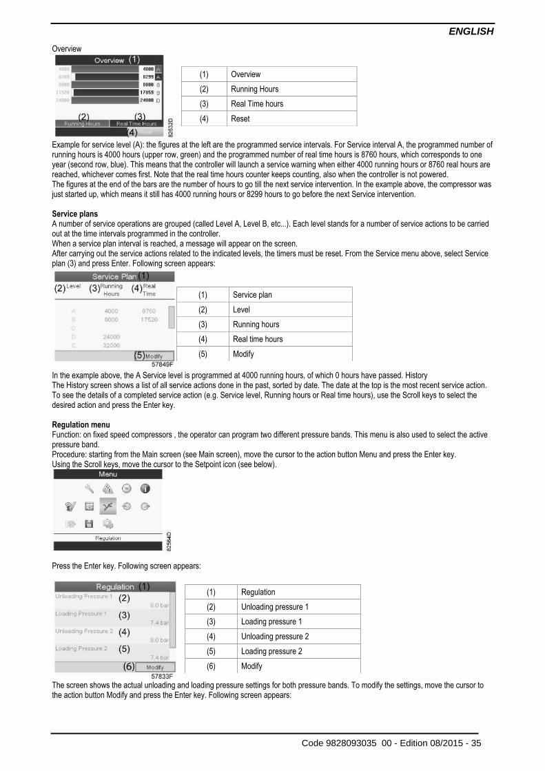
Overview
Example for service level (A): the figures at the left are the programmed service intervals. For Service interval A, the programmed number of running hours is 4000 hours (upper row, green) and the programmed number of real time hours is 8760 hours, which corresponds to one year (second row, blue). This means that the controller will launch a service warning when either 4000 running hours or 8760 real hours are reached, whichever comes first. Note that the real time hours counter keeps counting, also when the controller is not powered. The figures at the end of the bars are the number of hours to go till the next service intervention. In the example above, the compressor was just started up, which means it still has 4000 running hours or 8299 hours to go before the next Service intervention. Service plans A number of service operations are grouped (called Level A, Level B, etc...). Each level stands for a number of service actions to be carried out at the time intervals programmed in the controller. When a service plan interval is reached, a message will appear on the screen. After carrying out the service actions related to the indicated levels, the timers must be reset. From the Service menu above, select Service plan (3) and press Enter. Following screen appears:
In the example above, the A Service level is programmed at 4000 running hours, of which 0 hours have passed. History The History screen shows a list of all service actions done in the past, sorted by date. The date at the top is the most recent service action. To see the details of a completed service action (e.g. Service level, Running hours or Real time hours), use the Scroll keys to select the desired action and press the Enter key. Regulation menu Function: on fixed speed compressors , the operator can program two different pressure bands. This menu is also used to select the active pressure band. Procedure: starting from the Main screen (see Main screen), move the cursor to the action button Menu and press the Enter key. Using the Scroll keys, move the cursor to the Setpoint icon (see below).
Press the Enter key. Following screen appears:
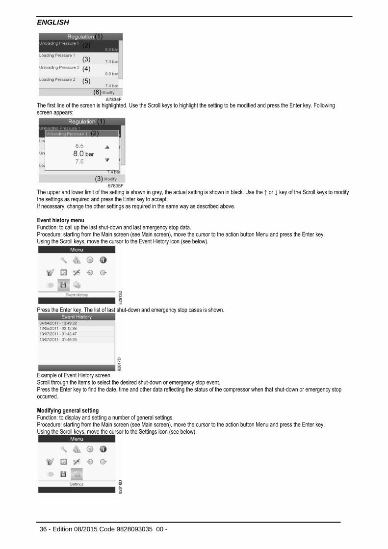
The screen shows the actual unloading and loading pressure settings for both pressure bands. To modify the settings, move the cursor to the action button Modify and press the Enter key. Following screen appears:
(1) Overview
(2) Running Hours
(3) Real Time hours
(4) Reset
(1) Service plan
(2) Level
(3) Running hours
(4) Real time hours
(5) Modify
(1) Regulation
(2) Unloading pressure 1
(3) Loading pressure 1
(4) Unloading pressure 2
(5) Loading pressure 2
(6) Modify
ENGLISH
36 - Edition 08/2015 Code 9828093035 00 -
The first line of the screen is highlighted. Use the Scroll keys to highlight the setting to be modified and press the Enter key. Following screen appears:
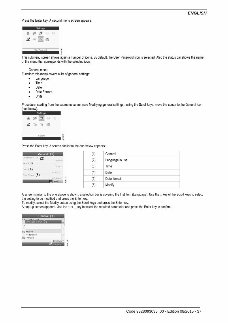
The upper and lower limit of the setting is shown in grey, the actual setting is shown in black. Use the ↑ or ↓ key of the Scroll keys to modify the settings as required and press the Enter key to accept. If necessary, change the other settings as required in the same way as described above. Event history menu Function: to call up the last shut-down and last emergency stop data. Procedure: starting from the Main screen (see Main screen), move the cursor to the action button Menu and press the Enter key. Using the Scroll keys, move the cursor to the Event History icon (see below).
Press the Enter key. The list of last shut-down and emergency stop cases is shown.
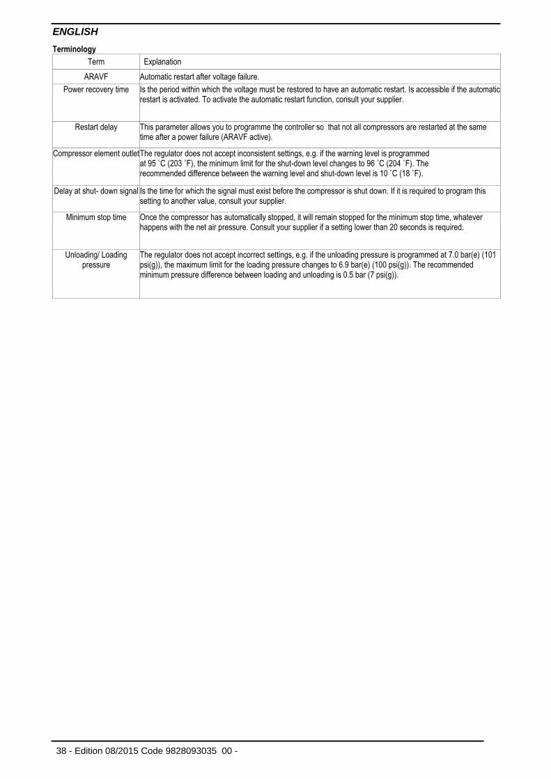
Example of Event History screen Scroll through the items to select the desired shut-down or emergency stop event. Press the Enter key to find the date, time and other data reflecting the status of the compressor when that shut-down or emergency stop occurred. Modifying general setting Function: to display and setting a number of general settings. Procedure: starting from the Main screen (see Main screen), move the cursor to the action button Menu and press the Enter key. Using the Scroll keys, move the cursor to the Settings icon (see below).
ENGLISH
Code 9828093035 00 - Edition 08/2015 - 37
Press the Enter key. A second menu screen appears:
This submenu screen shows again a number of icons. By default, the User Password icon is selected. Also the status bar shows the name of the menu that corresponds with the selected icon.
General menu Function: this menu covers a list of general settings:
Language
Time
Date
Date Format
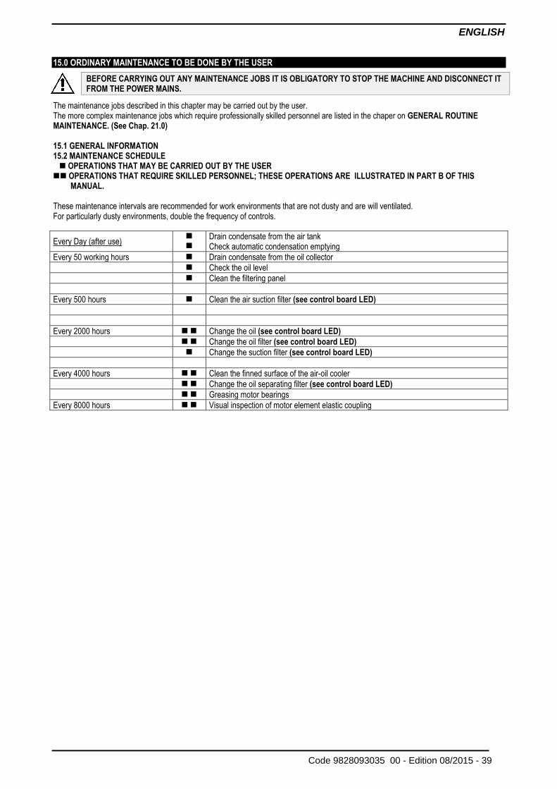
Units Procedure: starting from the submenu screen (see Modifying general settings), using the Scroll keys, move the cursor to the General icon (see below).
Press the Enter key. A screen similar to the one below appears:
A screen similar to the one above is shown, a selection bar is covering the first item (Language). Use the ↓ key of the Scroll keys to select the setting to be modified and press the Enter key. To modify, select the Modify button using the Scroll keys and press the Enter key. A pop-up screen appears. Use the ↑ or ↓ key to select the required parameter and press the Enter key to confirm.
(1) General
(2) Language in use
(3) Time
(4) Date
(5) Date format
(6) Modify
ENGLISH
38 - Edition 08/2015 Code 9828093035 00 -
Terminology
Term Explanation
ARAVF Automatic restart after voltage failure.
Power recovery time Is the period within which the voltage must be restored to have an automatic restart. Is accessible if the automatic restart is activated. To activate the automatic restart function, consult your supplier.
Restart delay This parameter allows you to programme the controller so that not all compressors are restarted at the same time after a power failure (ARAVF active).
Compressor element outlet The regulator does not accept inconsistent settings, e.g. if the warning level is programmed at 95 ˚C (203 ˚F), the minimum limit for the shut-down level changes to 96 ˚C (204 ˚F). The recommended difference between the warning level and shut-down level is 10 ˚C (18 ˚F).
Delay at shut- down signal Is the time for which the signal must exist before the compressor is shut down. If it is required to program this setting to another value, consult your supplier.
Minimum stop time Once the compressor has automatically stopped, it will remain stopped for the minimum stop time, whatever happens with the net air pressure. Consult your supplier if a setting lower than 20 seconds is required.
Unloading/ Loading pressure
The regulator does not accept incorrect settings, e.g. if the unloading pressure is programmed at 7.0 bar(e) (101 psi(g)), the maximum limit for the loading pressure changes to 6.9 bar(e) (100 psi(g)). The recommended minimum pressure difference between loading and unloading is 0.5 bar (7 psi(g)).
ENGLISH
Code 9828093035 00 - Edition 08/2015 - 39
15.0 ORDINARY MAINTENANCE TO BE DONE BY THE USER
BEFORE CARRYING OUT ANY MAINTENANCE JOBS IT IS OBLIGATORY TO STOP THE MACHINE AND DISCONNECT IT FROM THE POWER MAINS.
The maintenance jobs described in this chapter may be carried out by the user. The more complex maintenance jobs which require professionally skilled personnel are listed in the chaper on GENERAL ROUTINE MAINTENANCE. (See Chap. 21.0) 15.1 GENERAL INFORMATION 15.2 MAINTENANCE SCHEDULE OPERATIONS THAT MAY BE CARRIED OUT BY THE USER OPERATIONS THAT REQUIRE SKILLED PERSONNEL; THESE OPERATIONS ARE ILLUSTRATED IN PART B OF THIS
MANUAL. These maintenance intervals are recommended for work environments that are not dusty and are will ventilated. For particularly dusty environments, double the frequency of controls.
Every Day (after use)
Drain condensate from the air tank Check automatic condensation emptying
Every 50 working hours Drain condensate from the oil collector
Check the oil level
Clean the filtering panel
Every 500 hours Clean the air suction filter (see control board LED)
Every 2000 hours Change the oil (see control board LED)
Change the oil filter (see control board LED)
Change the suction filter (see control board LED)
Every 4000 hours Clean the finned surface of the air-oil cooler
Change the oil separating filter (see control board LED)
Greasing motor bearings
Every 8000 hours Visual inspection of motor element elastic coupling
ENGLISH
40 - Edition 08/2015 Code 9828093035 00 -
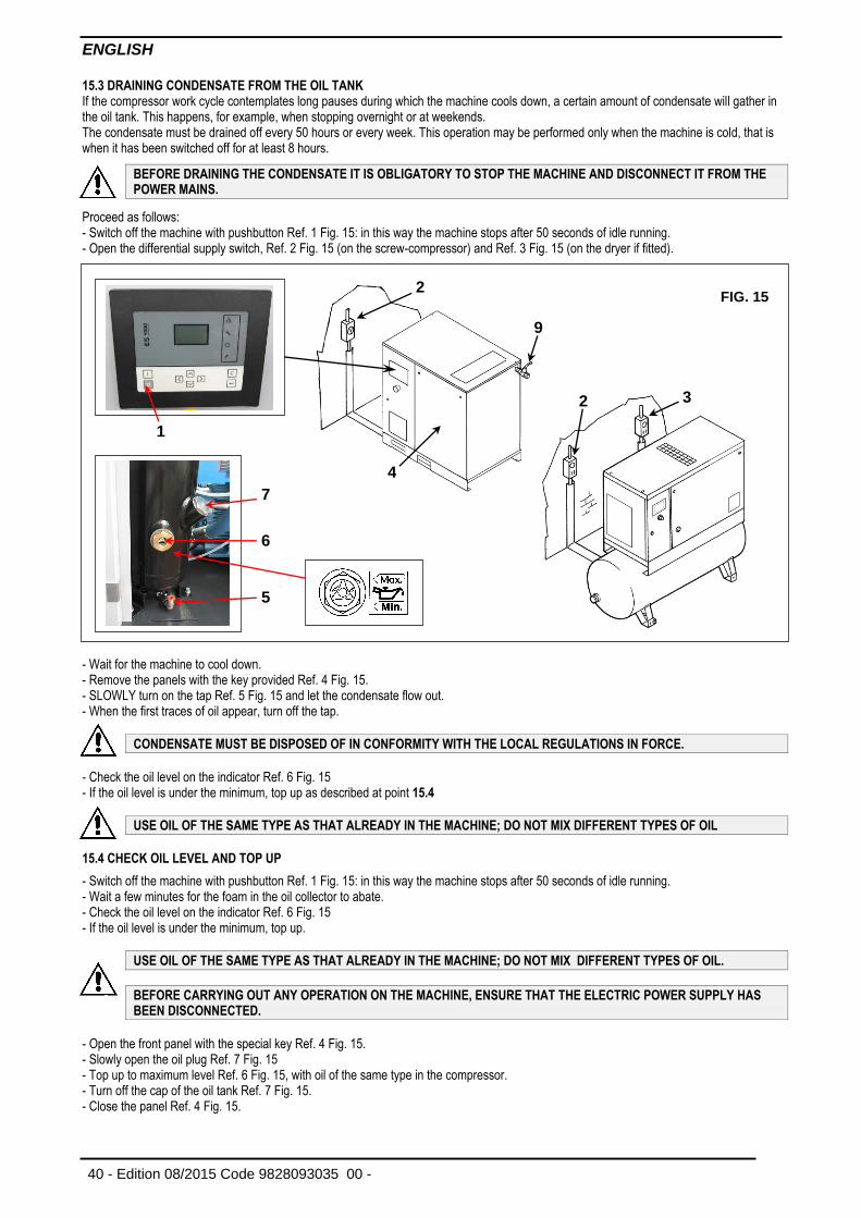
15.3 DRAINING CONDENSATE FROM THE OIL TANK If the compressor work cycle contemplates long pauses during which the machine cools down, a certain amount of condensate will gather in the oil tank. This happens, for example, when stopping overnight or at weekends. The condensate must be drained off every 50 hours or every week. This operation may be performed only when the machine is cold, that is when it has been switched off for at least 8 hours.
BEFORE DRAINING THE CONDENSATE IT IS OBLIGATORY TO STOP THE MACHINE AND DISCONNECT IT FROM THE POWER MAINS.
Proceed as follows: - Switch off the machine with pushbutton Ref. 1 Fig. 15: in this way the machine stops after 50 seconds of idle running. - Open the differential supply switch, Ref. 2 Fig. 15 (on the screw-compressor) and Ref. 3 Fig. 15 (on the dryer if fitted).
- Wait for the machine to cool down. - Remove the panels with the key provided Ref. 4 Fig. 15. - SLOWLY turn on the tap Ref. 5 Fig. 15 and let the condensate flow out. - When the first traces of oil appear, turn off the tap.
CONDENSATE MUST BE DISPOSED OF IN CONFORMITY WITH THE LOCAL REGULATIONS IN FORCE.
- Check the oil level on the indicator Ref. 6 Fig. 15 - If the oil level is under the minimum, top up as described at point 15.4
USE OIL OF THE SAME TYPE AS THAT ALREADY IN THE MACHINE; DO NOT MIX DIFFERENT TYPES OF OIL
15.4 CHECK OIL LEVEL AND TOP UP
- Switch off the machine with pushbutton Ref. 1 Fig. 15: in this way the machine stops after 50 seconds of idle running. - Wait a few minutes for the foam in the oil collector to abate. - Check the oil level on the indicator Ref. 6 Fig. 15 - If the oil level is under the minimum, top up.
USE OIL OF THE SAME TYPE AS THAT ALREADY IN THE MACHINE; DO NOT MIX DIFFERENT TYPES OF OIL.
BEFORE CARRYING OUT ANY OPERATION ON THE MACHINE, ENSURE THAT THE ELECTRIC POWER SUPPLY HAS BEEN DISCONNECTED.
- Open the front panel with the special key Ref. 4 Fig. 15. - Slowly open the oil plug Ref. 7 Fig. 15 - Top up to maximum level Ref. 6 Fig. 15, with oil of the same type in the compressor. - Turn off the cap of the oil tank Ref. 7 Fig. 15. - Close the panel Ref. 4 Fig. 15.
FIG. 15
1
5
6
7
9
2
4
2
3
ENGLISH
Code 9828093035 00 - Edition 08/2015 - 41
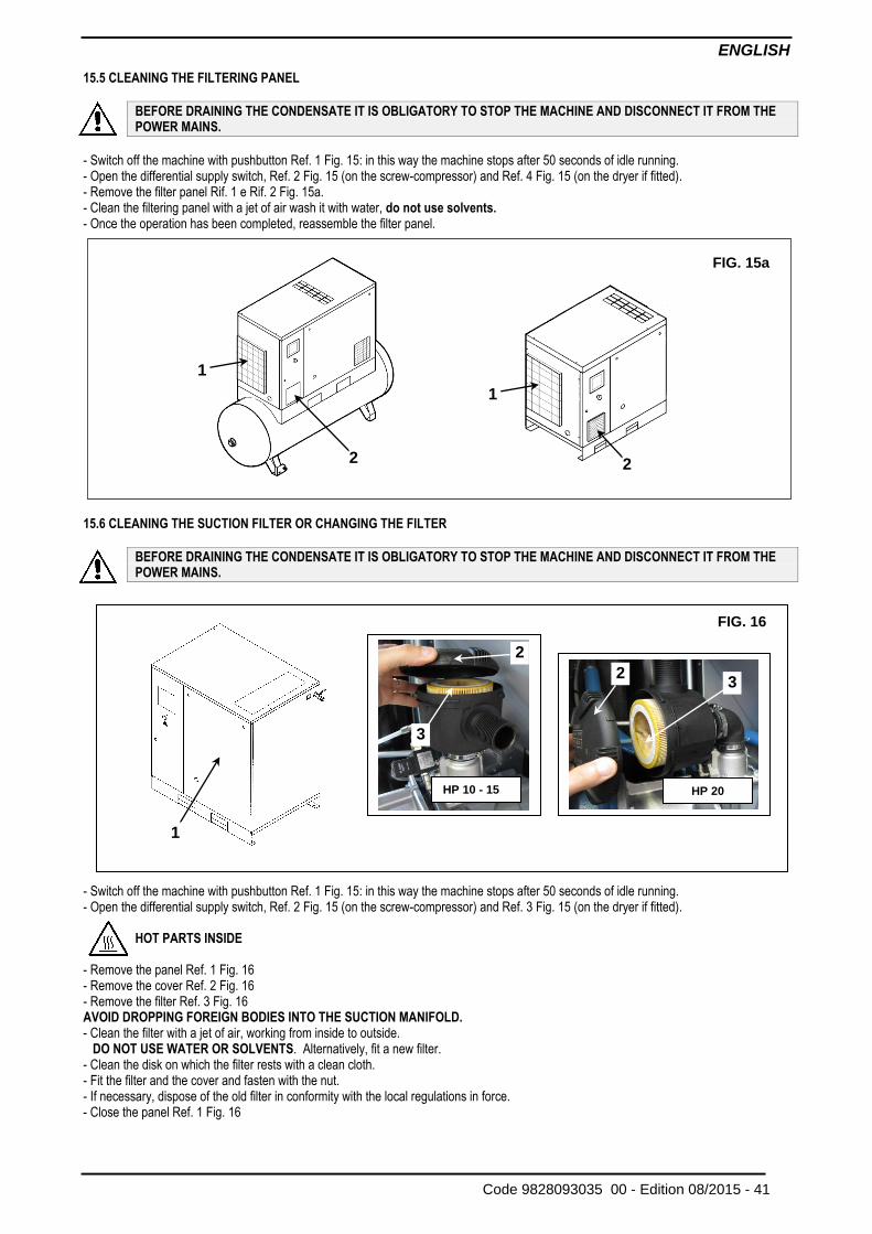
15.5 CLEANING THE FILTERING PANEL
BEFORE DRAINING THE CONDENSATE IT IS OBLIGATORY TO STOP THE MACHINE AND DISCONNECT IT FROM THE POWER MAINS.
- Switch off the machine with pushbutton Ref. 1 Fig. 15: in this way the machine stops after 50 seconds of idle running. - Open the differential supply switch, Ref. 2 Fig. 15 (on the screw-compressor) and Ref. 4 Fig. 15 (on the dryer if fitted). - Remove the filter panel Rif. 1 e Rif. 2 Fig. 15a. - Clean the filtering panel with a jet of air wash it with water, do not use solvents. - Once the operation has been completed, reassemble the filter panel.
15.6 CLEANING THE SUCTION FILTER OR CHANGING THE FILTER
BEFORE DRAINING THE CONDENSATE IT IS OBLIGATORY TO STOP THE MACHINE AND DISCONNECT IT FROM THE POWER MAINS.
- Switch off the machine with pushbutton Ref. 1 Fig. 15: in this way the machine stops after 50 seconds of idle running. - Open the differential supply switch, Ref. 2 Fig. 15 (on the screw-compressor) and Ref. 3 Fig. 15 (on the dryer if fitted).
HOT PARTS INSIDE - Remove the panel Ref. 1 Fig. 16 - Remove the cover Ref. 2 Fig. 16 - Remove the filter Ref. 3 Fig. 16 AVOID DROPPING FOREIGN BODIES INTO THE SUCTION MANIFOLD. - Clean the filter with a jet of air, working from inside to outside. DO NOT USE WATER OR SOLVENTS. Alternatively, fit a new filter. - Clean the disk on which the filter rests with a clean cloth. - Fit the filter and the cover and fasten with the nut. - If necessary, dispose of the old filter in conformity with the local regulations in force. - Close the panel Ref. 1 Fig. 16
FIG. 16
2 2
3
3
HP 10 - 15 HP 20
1
FIG. 15a
1
2
1
2
ENGLISH
42 - Edition 08/2015 Code 9828093035 00 -
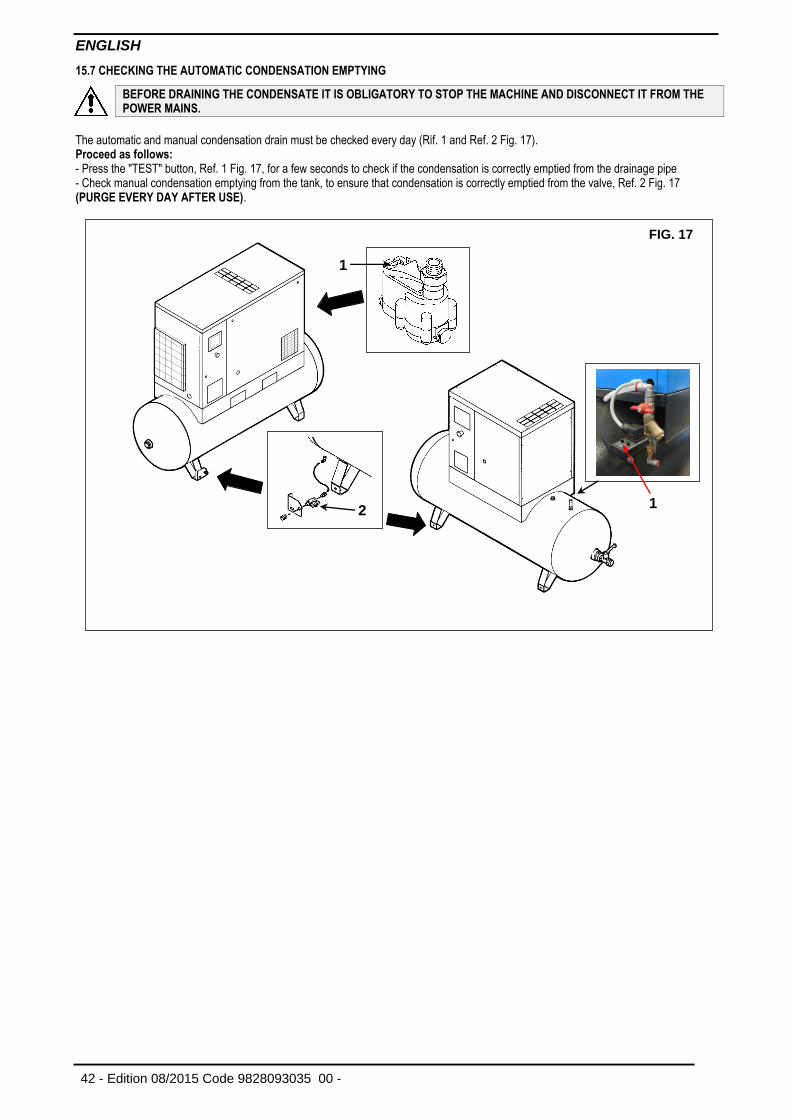
15.7 CHECKING THE AUTOMATIC CONDENSATION EMPTYING
BEFORE DRAINING THE CONDENSATE IT IS OBLIGATORY TO STOP THE MACHINE AND DISCONNECT IT FROM THE POWER MAINS.
The automatic and manual condensation drain must be checked every day (Rif. 1 and Ref. 2 Fig. 17). Proceed as follows:
- Press the "TEST" button, Ref. 1 Fig. 17, for a few seconds to check if the condensation is correctly emptied from the drainage pipe - Check manual condensation emptying from the tank, to ensure that condensation is correctly emptied from the valve, Ref. 2 Fig. 17 (PURGE EVERY DAY AFTER USE).
FIG. 17
1
2
1
ENGLISH
Code 9828093035 00 - Edition 08/2015 - 43
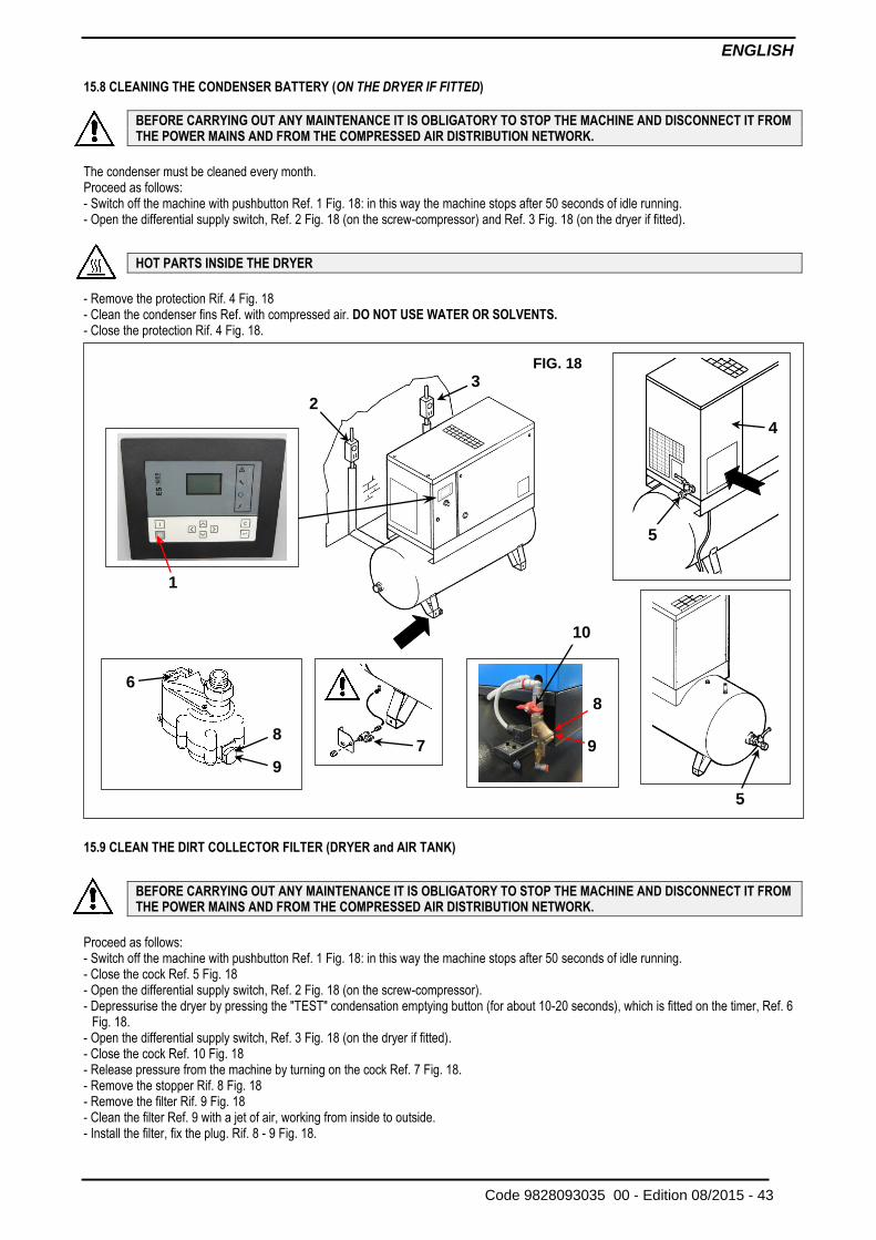
15.8 CLEANING THE CONDENSER BATTERY (ON THE DRYER IF FITTED)
BEFORE CARRYING OUT ANY MAINTENANCE IT IS OBLIGATORY TO STOP THE MACHINE AND DISCONNECT IT FROM THE POWER MAINS AND FROM THE COMPRESSED AIR DISTRIBUTION NETWORK.
The condenser must be cleaned every month. Proceed as follows:
- Switch off the machine with pushbutton Ref. 1 Fig. 18: in this way the machine stops after 50 seconds of idle running.
- Open the differential supply switch, Ref. 2 Fig. 18 (on the screw-compressor) and Ref. 3 Fig. 18 (on the dryer if fitted).
HOT PARTS INSIDE THE DRYER
- Remove the protection Rif. 4 Fig. 18 - Clean the condenser fins Ref. with compressed air. DO NOT USE WATER OR SOLVENTS. - Close the protection Rif. 4 Fig. 18.
15.9 CLEAN THE DIRT COLLECTOR FILTER (DRYER and AIR TANK)
BEFORE CARRYING OUT ANY MAINTENANCE IT IS OBLIGATORY TO STOP THE MACHINE AND DISCONNECT IT FROM THE POWER MAINS AND FROM THE COMPRESSED AIR DISTRIBUTION NETWORK.
Proceed as follows: - Switch off the machine with pushbutton Ref. 1 Fig. 18: in this way the machine stops after 50 seconds of idle running. - Close the cock Ref. 5 Fig. 18
- Open the differential supply switch, Ref. 2 Fig. 18 (on the screw-compressor). - Depressurise the dryer by pressing the "TEST" condensation emptying button (for about 10-20 seconds), which is fitted on the timer, Ref. 6
Fig. 18.
- Open the differential supply switch, Ref. 3 Fig. 18 (on the dryer if fitted). - Close the cock Ref. 10 Fig. 18 - Release pressure from the machine by turning on the cock Ref. 7 Fig. 18. - Remove the stopper Rif. 8 Fig. 18 - Remove the filter Rif. 9 Fig. 18 - Clean the filter Ref. 9 with a jet of air, working from inside to outside. - Install the filter, fix the plug. Rif. 8 - 9 Fig. 18.
FIG. 18
1
6
9
8
7
9
8
2
3
10
4
5
5
ENGLISH
44 - Edition 08/2015 Code 9828093035 00 -
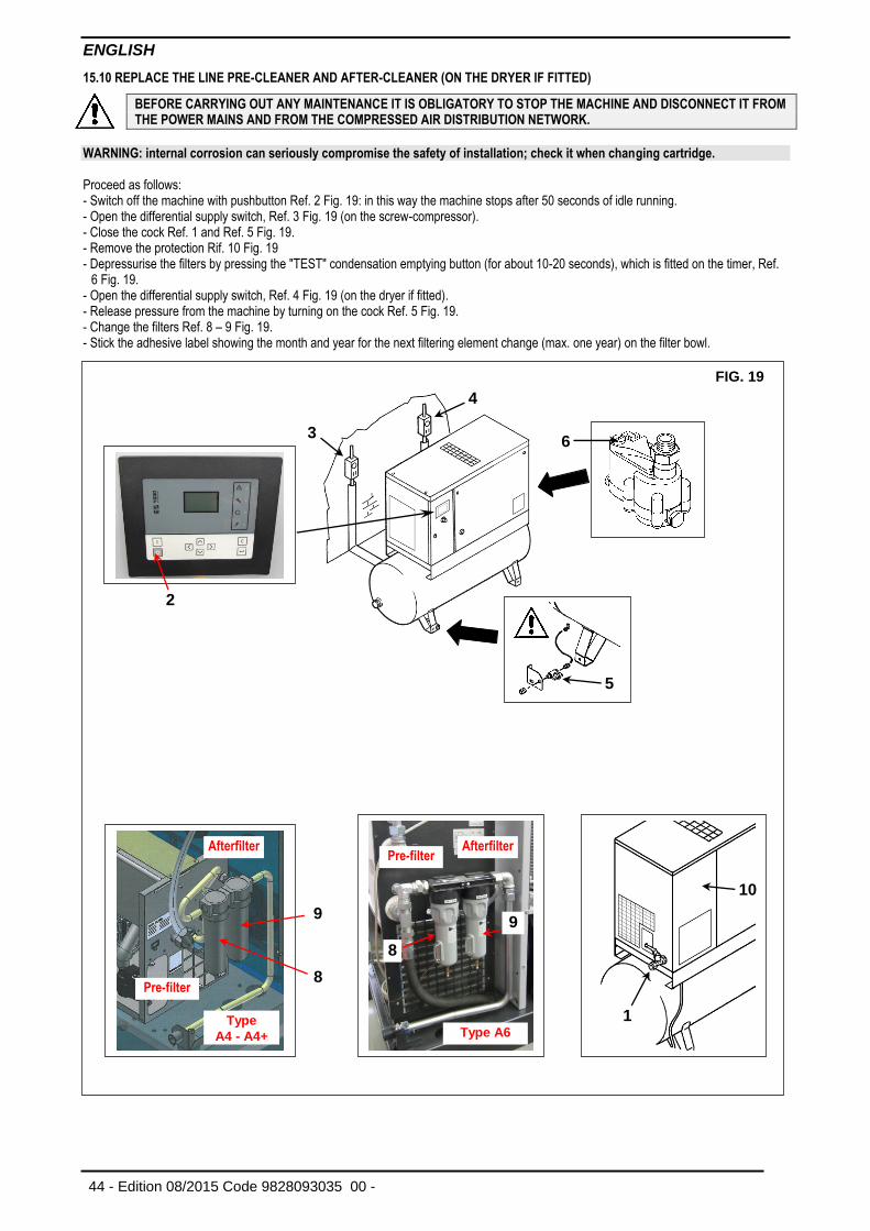
15.10 REPLACE THE LINE PRE-CLEANER AND AFTER-CLEANER (ON THE DRYER IF FITTED)
BEFORE CARRYING OUT ANY MAINTENANCE IT IS OBLIGATORY TO STOP THE MACHINE AND DISCONNECT IT FROM THE POWER MAINS AND FROM THE COMPRESSED AIR DISTRIBUTION NETWORK.
WARNING: internal corrosion can seriously compromise the safety of installation; check it when changing cartridge. Proceed as follows: - Switch off the machine with pushbutton Ref. 2 Fig. 19: in this way the machine stops after 50 seconds of idle running. - Open the differential supply switch, Ref. 3 Fig. 19 (on the screw-compressor). - Close the cock Ref. 1 and Ref. 5 Fig. 19. - Remove the protection Rif. 10 Fig. 19
- Depressurise the filters by pressing the "TEST" condensation emptying button (for about 10-20 seconds), which is fitted on the timer, Ref. 6 Fig. 19.
- Open the differential supply switch, Ref. 4 Fig. 19 (on the dryer if fitted). - Release pressure from the machine by turning on the cock Ref. 5 Fig. 19. - Change the filters Ref. 8 – 9 Fig. 19. - Stick the adhesive label showing the month and year for the next filtering element change (max. one year) on the filter bowl.
FIG. 19
2
3
4
6
5
8
9
Type
A4 - A4+
9
8
Type A6
10
1
Pre-filter
Afterfilter Pre-filter
Afterfilter
ENGLISH
Code 9828093035 00 - Edition 08/2015 - 45
16.0 PERIODS OF INACTIVITY If the machine has to remain inactive for a long period: - Close the cock Ref. 5 Fig. 18. - Depressurise the dryer by pressing the "TEST" condensation emptying button (for about 10-20 seconds) which is fitted on the timer, Ref. 6
Fig. 18 (on the dryer if fitted). - Switch off the machine with pushbutton Ref. 1 Fig. 18: in this way the machine stops after 50 seconds of idle running. - Open the differential supply switch, Ref. 2 Fig. 18 (on the screw-compressor) and Ref. 3 Fig. 18 (on the dryer if fitted). - Release pressure from the machine by turning on the cocks Ref. 7 Fig. 18. - Close the cocks Rif. 7 Fig. 18 off again after discharging all the residual air pressure During periods of inactivity the weather must be protected against atmospheric agents, dust and humidity which could damage the motor and the electrical system. To restart the machine after periods of inactivity, consult the manufacturer technical assistance service.
17.0 SCRAPPING THE UNIT If the machine is to be scrapped, it must be dismantled into parts of the same material, to be disposed of according to the local regulations in force.
ALWAYS RESPECT THE REGULATIONS IN FORCE FOR DISPOSING OF OLD OIL AND OTHER POLLUTING MATERIALS SUCH AS SOUND-DEADENING, FOAM, ETC.
ENGLISH
46 - Edition 08/2015 Code 9828093035 00 -
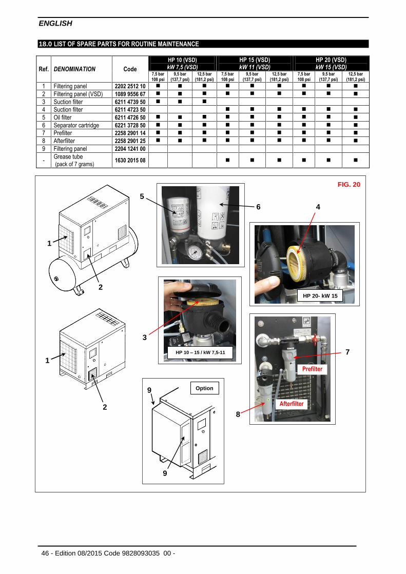
18.0 LIST OF SPARE PARTS FOR ROUTINE MAINTENANCE
Ref. DENOMINATION Code
HP 10 (VSD)
kW 7,5 (VSD) HP 15 (VSD) kW 11 (VSD)
HP 20 (VSD) kW 15 (VSD)
7,5 bar 108 psi
9,5 bar (137,7 psi)
12,5 bar (181,2 psi)
7,5 bar 108 psi
9,5 bar (137,7 psi)
12,5 bar (181,2 psi)
7,5 bar 108 psi
9,5 bar (137,7 psi)
12,5 bar (181,2 psi)
1 Filtering panel 2202 2512 10
2 Filtering panel (VSD) 1089 9556 67
3 Suction filter 6211 4739 50
4 Suction filter 6211 4723 50
5 Oil filter 6211 4726 50
6 Separator cartridge 6221 3728 50
7 Prefilter 2258 2901 14
8 Afterfilter 2258 2901 25
9 Filtering panel 2204 1241 00
- Grease tube (pack of 7 grams)
1630 2015 08
FIG. 20
3
4
6
HP 10 – 15 / kW 7,5-11
HP 20- kW 15
1
2
Prefilter
Afterfilter
7
8
Option
9
9
5
2
1
ENGLISH
Code 9828093035 00 - Edition 08/2015 - 47
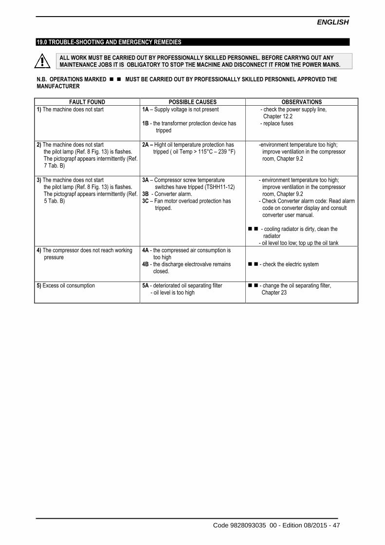
19.0 TROUBLE-SHOOTING AND EMERGENCY REMEDIES
ALL WORK MUST BE CARRIED OUT BY PROFESSIONALLY SKILLED PERSONNEL. BEFORE CARRYNG OUT ANY MAINTENANCE JOBS IT IS OBLIGATORY TO STOP THE MACHINE AND DISCONNECT IT FROM THE POWER MAINS.
N.B. OPERATIONS MARKED MUST BE CARRIED OUT BY PROFESSIONALLY SKILLED PERSONNEL APPROVED THE MANUFACTURER
FAULT FOUND POSSIBLE CAUSES OBSERVATIONS
1) The machine does not start
1A – Supply voltage is not present 1B - the transformer protection device has
tripped
- check the power supply line, Chapter 12.2
- replace fuses
2) The machine does not start the pilot lamp (Ref. 8 Fig. 13) is flashes. The pictograpf appears intermittently (Ref.
7 Tab. B)
2A – Hight oil temperature protection has tripped ( oil Temp > 115°C – 239 °F)
-environment temperature too high; improve ventilation in the compressor room, Chapter 9.2
3) The machine does not start the pilot lamp (Ref. 8 Fig. 13) is flashes. The pictograpf appears intermittently (Ref.
5 Tab. B)
3A – Compressor screw temperature switches have tripped (TSHH11-12)
3B - Converter alarm. 3C – Fan motor overload protection has
tripped.
- environment temperature too high; improve ventilation in the compressor room, Chapter 9.2
- Check Converter alarm code: Read alarm code on converter display and consult converter user manual.
- cooling radiator is dirty, clean the
radiator - oil level too low; top up the oil tank
4) The compressor does not reach working pressure
4A - the compressed air consumption is too high 4B - the discharge electrovalve remains
closed.
- check the electric system
5) Excess oil consumption 5A - deteriorated oil separating filter - oil level is too high
- change the oil separating filter, Chapter 23
ENGLISH
48 - Edition 08/2015 Code 9828093035 00 -
PART “B”
THIS PART “B” OF THE INSTRUCTIONS MANUAL IS RESERVED FOR PROFESSIONALLY SKILLED PERSONNEL APPROVED THE MANUFACTURER.
WARNING: THE INVERTER REMAINS CHARGED WITH HIGH VOLTAGE FOR 15 MINUTES AFTER THE MASTER SWITCH HAS BEEN OPENED. ALWAYS WAIT FOR 15 MINUTES BEFORE REMOVING THE FRONT COVER (INSTRUMENT PANEL) OR DISCONNECT CONVERTER SUPPLY WIRES OR MOTOR CABLE. ALWAYS WAIT FOR FIVE MINUTES BEFORE REMOVING THE FRONT COVER (INSTRUMENT PANEL). USE A SPECIFIC INSTRUMENT TO CHECK THAT THERE ARE NO DANGEROUS VOLTAGES BEFORE PERFORMING OPERATIONS ON THE INVERTER OR MOTOR.
20.0 STARTING UP
BEFORE CARRYING OUT ANY OPERATION ON THE MACHINE, ENSURE THAT THE ELECTRIC POWER SUPPLY HAS BEEN DISCONNECTED.
20.1 PREPARING FOR SETTING UP After checking everything as indicated in Chap. 12, folow the instructions in Fig. 21 - Fit the sound-deadening panels Ref. 1 Fig 21 These parts are packed inside the bodywork. 20.2 PRELIMINART CHECKS - Check the oil level Ref. 2 Fig. 21 when supplied the machine is filled with oil;if the oil is not at the correct level, top up with the same oil as
the original type. If more than 3 months have passed between the inspection in the factory and the date of installation, lubricate the screw group before starting up, following the procedure described below: - Remove the cover Ref. 3 Fig. 21 - Remove the air filter Ref. 4 Fig. 21 - Pour a little oil into the suction unit. - Reassemble the air filter Ref. 4 Fig. 21 - Reassemble the cover Ref. 3 Fig. 21 If more than 6 months have passed between the inspection in the factory and the date of installation, consul the Manufacturer assistance service.
FIG. 21 3
OIL
2
4
1
1
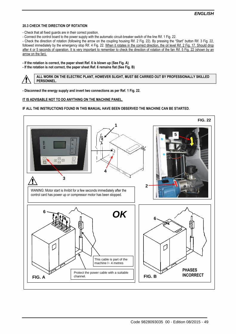
ENGLISH
Code 9828093035 00 - Edition 08/2015 - 49
20.3 CHECK THE DIRECTION OF ROTATION
- Check that all fixed guards are in their correct position. - Connect the control board to the power supply with the automatic circuit-breaker switch of the line Rif. 1 Fig. 22. - Check the direction of rotation (following the arrow on the coupling housing Rif. 2 Fig. 22). By pressing the “Start” button Rif. 3 Fig. 22, followed immediately by the emergency stop Rif. 4 Fig. 22. When it rotates in the correct direction, the oil level Rif. 2 Fig. 17. Should drop after 4 or 5 seconds of operation. It is very important to remember to check the direction of rotation of the fan Rif. 5 Fig. 22 (shown by an arrow on the fan). - If the rotation is correct, the paper sheet Ref. 6 is blown up (See Fig. A) - If the rotation is not correct, the paper sheet Ref. 6 remains flat (See Fig. B)
ALL WORK ON THE ELECTRIC PLANT, HOWEVER SLIGHT, MUST BE CARRIED OUT BY PROFESSIONALLY SKILLED PERSONNEL.
- Disconnect the energy supply and invert two connections as per Ref. 1 Fig. 22. IT IS ADVISABLE NOT TO DO ANYTHING ON THE MACHINE PANEL. IF ALL THE INSTRUCTIONS FOUND IN THIS MANUAL HAVE BEEN OBSERVED THE MACHINE CAN BE STARTED.
This cable is part of the machine l~ 4 metres
Protect the power cable with a suitable channel.
OK
FIG. B FIG. A
FIG. 22
1
2
3
4
5
6
6
WANING: Motor start is ihnibit for a few seconds immediately after the control card has power up or compressor motor has been stopped.
PHASES INCORRECT
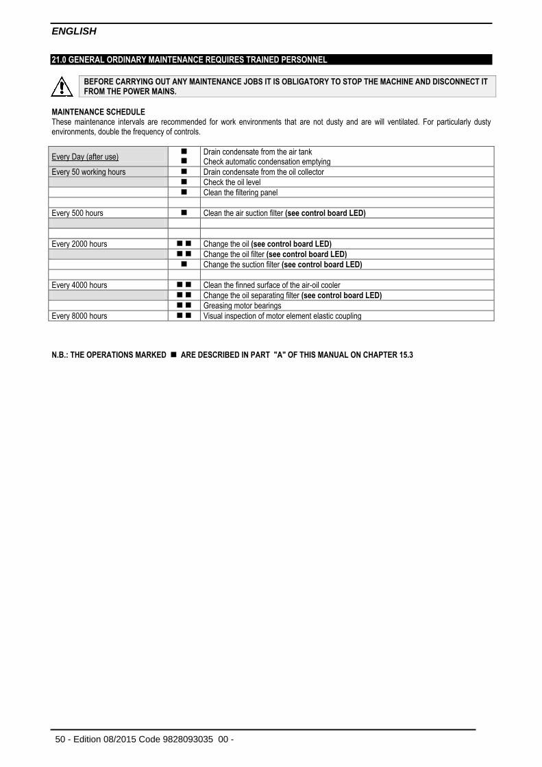
ENGLISH
50 - Edition 08/2015 Code 9828093035 00 -
21.0 GENERAL ORDINARY MAINTENANCE REQUIRES TRAINED PERSONNEL
BEFORE CARRYING OUT ANY MAINTENANCE JOBS IT IS OBLIGATORY TO STOP THE MACHINE AND DISCONNECT IT FROM THE POWER MAINS.
MAINTENANCE SCHEDULE These maintenance intervals are recommended for work environments that are not dusty and are will ventilated. For particularly dusty environments, double the frequency of controls.
Every Day (after use)
Drain condensate from the air tank Check automatic condensation emptying
Every 50 working hours Drain condensate from the oil collector
Check the oil level
Clean the filtering panel
Every 500 hours Clean the air suction filter (see control board LED)
Every 2000 hours Change the oil (see control board LED)
Change the oil filter (see control board LED)
Change the suction filter (see control board LED)
Every 4000 hours Clean the finned surface of the air-oil cooler
Change the oil separating filter (see control board LED)
Greasing motor bearings
Every 8000 hours Visual inspection of motor element elastic coupling
N.B.: THE OPERATIONS MARKED ARE DESCRIBED IN PART "A" OF THIS MANUAL ON CHAPTER 15.3
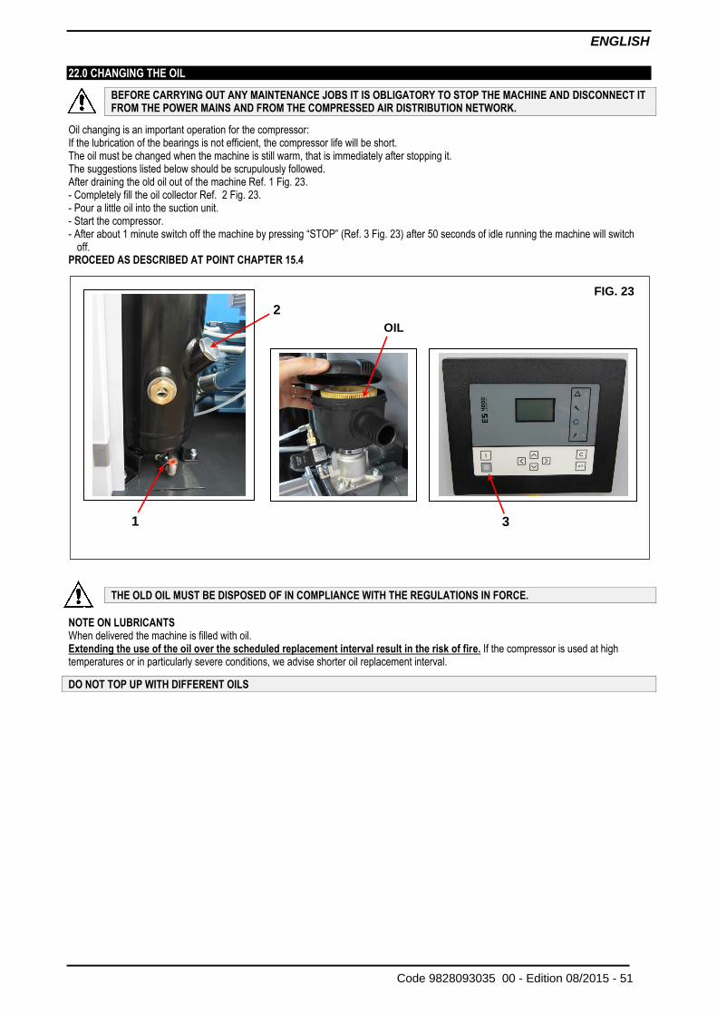
ENGLISH
Code 9828093035 00 - Edition 08/2015 - 51
22.0 CHANGING THE OIL
BEFORE CARRYING OUT ANY MAINTENANCE JOBS IT IS OBLIGATORY TO STOP THE MACHINE AND DISCONNECT IT FROM THE POWER MAINS AND FROM THE COMPRESSED AIR DISTRIBUTION NETWORK.
Oil changing is an important operation for the compressor: If the lubrication of the bearings is not efficient, the compressor life will be short. The oil must be changed when the machine is still warm, that is immediately after stopping it. The suggestions listed below should be scrupulously followed. After draining the old oil out of the machine Ref. 1 Fig. 23. - Completely fill the oil collector Ref. 2 Fig. 23. - Pour a little oil into the suction unit. - Start the compressor. - After about 1 minute switch off the machine by pressing “STOP” (Ref. 3 Fig. 23) after 50 seconds of idle running the machine will switch
off. PROCEED AS DESCRIBED AT POINT CHAPTER 15.4
THE OLD OIL MUST BE DISPOSED OF IN COMPLIANCE WITH THE REGULATIONS IN FORCE.
NOTE ON LUBRICANTS When delivered the machine is filled with oil. Extending the use of the oil over the scheduled replacement interval result in the risk of fire. If the compressor is used at high temperatures or in particularly severe conditions, we advise shorter oil replacement interval.
DO NOT TOP UP WITH DIFFERENT OILS
2 FIG. 23
3
2
OIL
1
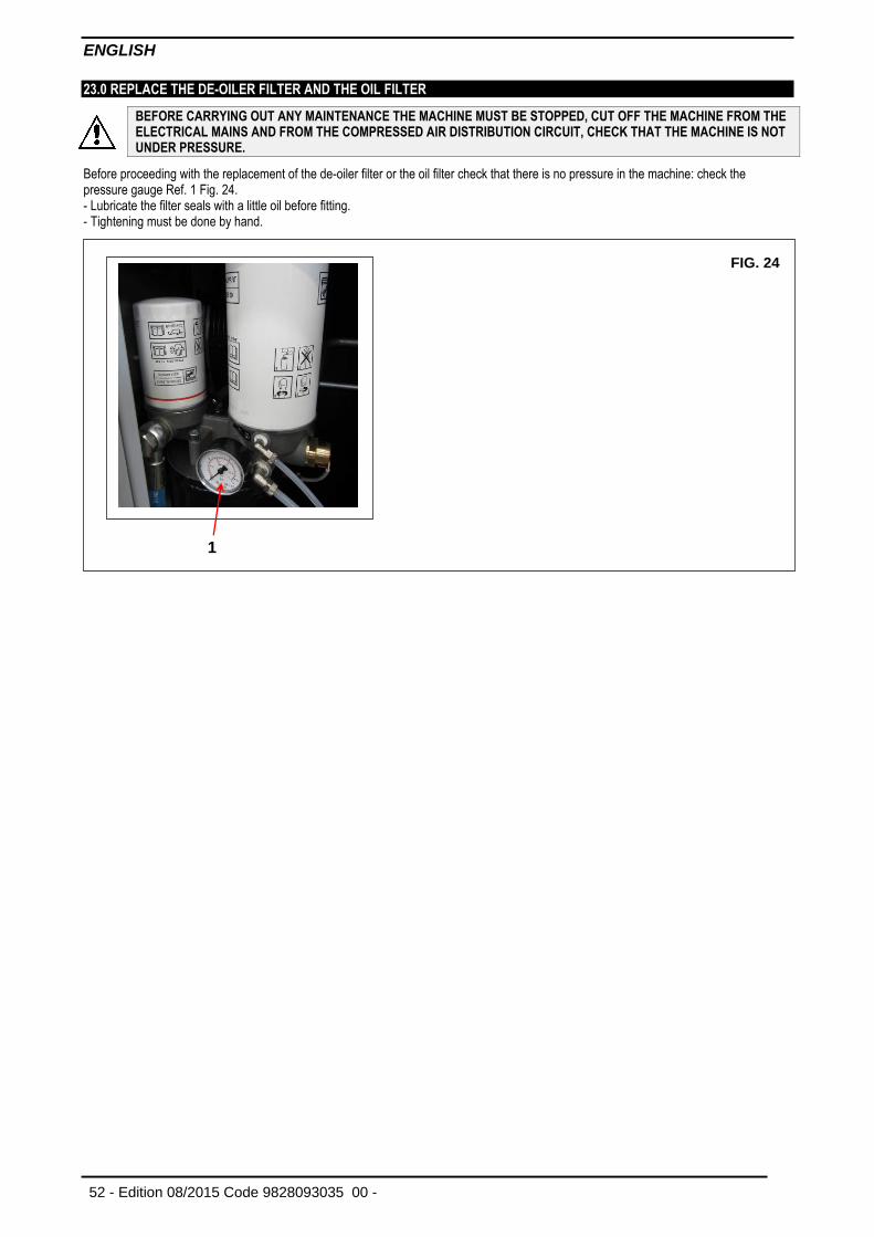
ENGLISH
52 - Edition 08/2015 Code 9828093035 00 -
23.0 REPLACE THE DE-OILER FILTER AND THE OIL FILTER
BEFORE CARRYING OUT ANY MAINTENANCE THE MACHINE MUST BE STOPPED, CUT OFF THE MACHINE FROM THE ELECTRICAL MAINS AND FROM THE COMPRESSED AIR DISTRIBUTION CIRCUIT, CHECK THAT THE MACHINE IS NOT UNDER PRESSURE.
Before proceeding with the replacement of the de-oiler filter or the oil filter check that there is no pressure in the machine: check the pressure gauge Ref. 1 Fig. 24. - Lubricate the filter seals with a little oil before fitting. - Tightening must be done by hand.
FIG. 24
1
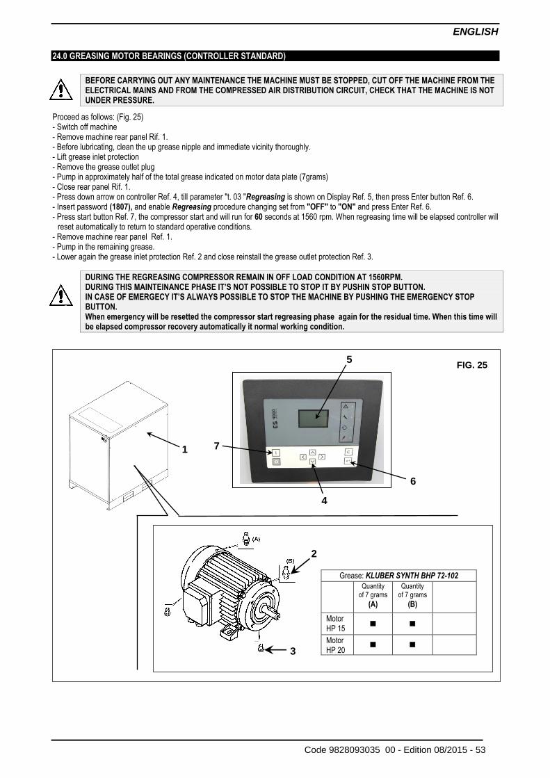
ENGLISH
Code 9828093035 00 - Edition 08/2015 - 53
24.0 GREASING MOTOR BEARINGS (CONTROLLER STANDARD)
BEFORE CARRYING OUT ANY MAINTENANCE THE MACHINE MUST BE STOPPED, CUT OFF THE MACHINE FROM THE ELECTRICAL MAINS AND FROM THE COMPRESSED AIR DISTRIBUTION CIRCUIT, CHECK THAT THE MACHINE IS NOT UNDER PRESSURE.
Proceed as follows: (Fig. 25) - Switch off machine - Remove machine rear panel Rif. 1. - Before lubricating, clean the up grease nipple and immediate vicinity thoroughly. - Lift grease inlet protection - Remove the grease outlet plug - Pump in approximately half of the total grease indicated on motor data plate (7grams) - Close rear panel Rif. 1. - Press down arrow on controller Ref. 4, till parameter "t. 03 "Regreasing is shown on Display Ref. 5, then press Enter button Ref. 6. - Insert password (1807), and enable Regreasing procedure changing set from "OFF" to "ON" and press Enter Ref. 6. - Press start button Ref. 7, the compressor start and will run for 60 seconds at 1560 rpm. When regreasing time will be elapsed controller will
reset automatically to return to standard operative conditions. - Remove machine rear panel Ref. 1. - Pump in the remaining grease. - Lower again the grease inlet protection Ref. 2 and close reinstall the grease outlet protection Ref. 3.
DURING THE REGREASING COMPRESSOR REMAIN IN OFF LOAD CONDITION AT 1560RPM. DURING THIS MAINTEINANCE PHASE IT’S NOT POSSIBLE TO STOP IT BY PUSHIN STOP BUTTON. IN CASE OF EMERGECY IT’S ALWAYS POSSIBLE TO STOP THE MACHINE BY PUSHING THE EMERGENCY STOP BUTTON. When emergency will be resetted the compressor start regreasing phase again for the residual time. When this time will be elapsed compressor recovery automatically it normal working condition.
FIG. 25
1
Grease: KLUBER SYNTH BHP 72-102
Quantity of 7 grams
(A)
Quantity of 7 grams
(B)
Motor
HP 15
Motor
HP 20
3
5
6
4
7
2
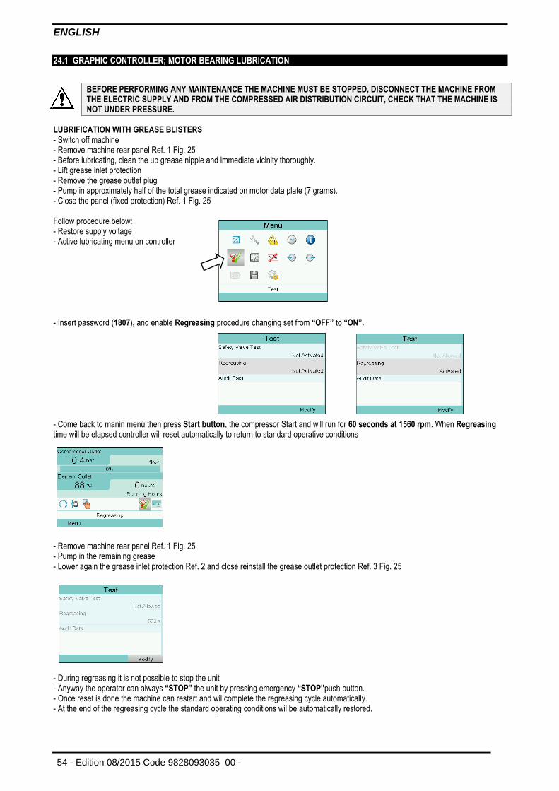
ENGLISH
54 - Edition 08/2015 Code 9828093035 00 -
24.1 GRAPHIC CONTROLLER; MOTOR BEARING LUBRICATION
BEFORE PERFORMING ANY MAINTENANCE THE MACHINE MUST BE STOPPED, DISCONNECT THE MACHINE FROM THE ELECTRIC SUPPLY AND FROM THE COMPRESSED AIR DISTRIBUTION CIRCUIT, CHECK THAT THE MACHINE IS NOT UNDER PRESSURE.
LUBRIFICATION WITH GREASE BLISTERS - Switch off machine - Remove machine rear panel Ref. 1 Fig. 25 - Before lubricating, clean the up grease nipple and immediate vicinity thoroughly. - Lift grease inlet protection - Remove the grease outlet plug - Pump in approximately half of the total grease indicated on motor data plate (7 grams). - Close the panel (fixed protection) Ref. 1 Fig. 25 Follow procedure below: - Restore supply voltage - Active lubricating menu on controller - Insert password (1807), and enable Regreasing procedure changing set from “OFF” to “ON”. - Come back to manin menù then press Start button, the compressor Start and will run for 60 seconds at 1560 rpm. When Regreasing time will be elapsed controller will reset automatically to return to standard operative conditions
- Remove machine rear panel Ref. 1 Fig. 25 - Pump in the remaining grease - Lower again the grease inlet protection Ref. 2 and close reinstall the grease outlet protection Ref. 3 Fig. 25
- During regreasing it is not possible to stop the unit - Anyway the operator can always “STOP” the unit by pressing emergency “STOP”push button. - Once reset is done the machine can restart and wil complete the regreasing cycle automatically. - At the end of the regreasing cycle the standard operating conditions wil be automatically restored.
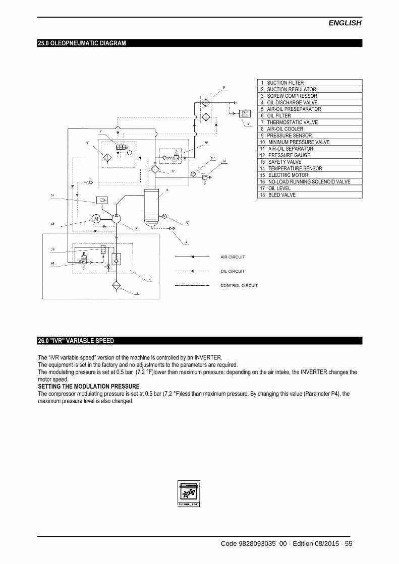
ENGLISH
Code 9828093035 00 - Edition 08/2015 - 55
25.0 OLEOPNEUMATIC DIAGRAM
26.0 "IVR" VARIABLE SPEED The “IVR variable speed” version of the machine is controlled by an INVERTER. The equipment is set in the factory and no adjustments to the parameters are required. The modulating pressure is set at 0.5 bar (7,2 °F)lower than maximum pressure: depending on the air intake, the INVERTER changes the motor speed. SETTING THE MODULATION PRESSURE The compressor modulating pressure is set at 0.5 bar (7,2 °F)less than maximum pressure. By changing this value (Parameter P4), the maximum pressure level is also changed.
AIR CIRCUIT
OIL CIRCUIT
CONTROL CIRCUIT
1 SUCTION FILTER
2 SUCTION REGULATOR
3 SCREW COMPRESSOR
4 OIL DISCHARGE VALVE
5 AIR-OIL PRESEPARATOR
6 OIL FILTER
7 THERMOSTATIC VALVE
8 AIR-OIL COOLER
9 PRESSURE SENSOR
10 MINIMUM PRESSURE VALVE
11 AIR-OIL SEPARATOR
12 PRESSURE GAUGE
13 SAFETY VALVE
14 TEMPERATURE SENSOR
15 ELECTRIC MOTOR
16 NO-LOAD RUNNING SOLENOID VALVE
17 OIL LEVEL
18 BLED VALVE