Signing UEFI Applications and Drivers for UEFI...
49
Version 1.31 3/8/2013 i Signing UEFI Applications and Drivers for UEFI Secure Boot February 27, 2013 Revision 1.31
Transcript of Signing UEFI Applications and Drivers for UEFI...
Version 1.31 3/8/2013 i
Signing UEFI Applications and Drivers for UEFI Secure Boot
February 27, 2013
Revision 1.31

Revision History Revision Revision History Date
0.1
0.2
0.21
0.22
0.23
0.55
0.56
0.57
0.58
0.59
1.0
1.1
1.2
1.3
Initial draft without OVMF
Cleanup & reorganize
Tech writer cleanup. Add reference to App. A of the shell book
Update Custom Mode Diagram Add OVMF section. Update Using Custom Mode section
Reviewed by Psi Security Subteam
Update OVMF details
Add Nt32Pkg details, Update where to get signing tools, Add Custom Mode Setup Screen shots.
Add review comments from architects.
Tech writer review
Add section: Image Verification Rules, Add nt32Pkg checkin rev.
Remove ImageVerification PCD description since it does not apply to images signed by X509 certificates. Add link to the Signing tools tab on the Secure Boot page on tianocore for the latest info on Linux signing tools.
Add description and reference to of the certificate file format. Add section on images with multiple signatures and link to more info on tianocore. Add that some tools require admin prvileges. Add details about the KEK & DB GUIDs. Update image verification flow description with diagram. Add additional screen shots of custom mode. EDK2 to EDK II.
Updates and clarifications related to UEFI Spec conformance regarding KEK and DB usage
2/1/2012
2/2/2012
2/7/2012
2/8/2012
2/9/2012
2/14/2012
3/5/2012
3/28/2012
4/2/2012
4/3/2012
4/11/2012
5/7/2012
7/13/2012
12/12/2012
1.4 Add reference to the Secure Boot Dual Boot videos on YouTube. 2/27/2013
Add commands for generating PK with openssl. Reference the UEFI CA KEK and DB certificates at Microsoft.com

Version 1.31 3/8/2013 3
Contents Revision History ...................................................................................................................... ii
Contents 3
1 Secure Booting UEFI Drivers and Applications ....................................................... 5 1.1 UEFI Secure Boot Overview ...................................................................... 5
1.1.1 Image Formats .......................................................................... 5 1.1.2 UEFI Secure Boot Policy ............................................................. 6 1.1.3 Additional Information ................................................................ 6 1.1.4 Document Precedence ................................................................ 6
1.2 UEFI Secure Boot’s Authenticated Variables ............................................... 7 1.2.1 Overview of Authenticated Variables ............................................ 7 1.2.2 Types of Authenticated Variables ................................................. 8 1.2.3 Secure Boot’s Authenticated Variable Descriptions ......................... 8
1.3 Image Authorization Flow ........................................................................ 9 1.4 Signing UEFI Images For Production and Release ....................................... 11 1.5 Signing UEFI Images For Development and Test ........................................ 12
1.5.1 Microsoft Windows * Hosted Signing Tools ................................... 12 1.5.2 Dual Booting Windows 8 * and Ubuntu Linux ............................... 18 1.5.3 Linux Hosted Signing Tools ........................................................ 19 1.5.4 Images with Multiple Signatures ................................................. 19 1.5.5 Image Verification Rules ............................................................ 19
1.6 Convert the Signed Driver to a .rom File ................................................... 20 1.7 Install the Signed Driver ......................................................................... 20 1.8 Adding a Signed Driver to the Boot Sequence ............................................ 21 1.9 Deploying Secure Boot Image and Certificate Policy ................................... 21
1.9.1 Secure Boot Setup & User Mode ................................................. 21 1.9.2 Secure Boot Setup Standard and Custom Mode .......................... 22 1.9.3 Using Secure Boot Custom Mode ................................................ 23 1.9.4 Secure Boot Custom ModeSetup Screens ..................................... 23
1.10 UEFI Secure Boot Scenarios .................................................................... 40 1.10.1 A signed UEFI image whose signing certificate or signature is enrolled.
.............................................................................................. 40 1.10.2 An unsigned image whose signature is not enrolled. ..................... 41 1.10.3 A signed driver whose signature is enrolled and an unsigned driver
whose signature is not enrolled. ................................................. 41 1.10.4 Booting an OS using a signed & enrolled driver. ........................... 42
1.11 Using OVMF with UEFI Secure Boot .......................................................... 42 1.11.1 Overview ................................................................................. 42 1.11.2 Getting QEMU .......................................................................... 42 1.11.3 Building OVMF .......................................................................... 43 1.11.4 CryptoPkg OpenSslLib Dependency ............................................. 43 1.11.5 Enabling UEFI Secure Boot in OVMF ............................................ 43 1.11.6 Source Level Debugger ............................................................. 44 1.11.7 Running OVMF with QEMU ......................................................... 44 1.11.8 Enabling or Modifying UEFI Secure Boot in OVMF .......................... 46 1.11.9 QEMU Notes ............................................................................. 46
1.12 Using Nt32PKG with UEFI Secure Boot ...................................................... 47
1.12.1 Overview ................................................................................. 47 1.12.2 Building Nt32Pkg ...................................................................... 47 1.12.3 CryptoPkg OpenSslLib Dependency ............................................. 47 1.12.4 Enabling UEFI Secure Boot in Nt32Pkg ........................................ 47 1.12.5 Running Nt32Pkg ...................................................................... 48 1.12.6 Enabling or Modifying UEFI Secure Boot in Nt32Pkg ...................... 49
Figures
Figure 1 Authenticated Variable Layout................................................................. 8 Figure 2 Image Authorization Flow ...................................................................... 11 Figure 3 Image Authentication Failed .................................................................. 11 Figure 4 Setup password for TestRoot.pvk ........................................................... 15 Figure 5 Setup password for TestSub.pvk ............................................................ 16 Figure 6 Input password of TestRoot.pvk to sign TestSub.cer ................................. 17 Figure 7 Checking the Value of the SetupMode Architectural Variable ...................... 22 Figure 8 Standard Mode Screen .......................................................................... 24 Figure 9 Secure Boot Configuration - Disabled ...................................................... 25 Figure 10 Secure Boot Configuration - Enabled ..................................................... 26 Figure 11 Disable Secure Boot Screen ................................................................. 27 Figure 12 Custom Secure Boot Mode Options Screen ............................................. 28 Figure 13 PK Options Screen .............................................................................. 29 Figure 14 Enroll PK Screen ................................................................................. 30 Figure 15 - Enroll PK Screen File Explorer ............................................................ 31 Figure 16 - Enroll PK file TestRoot.cer ................................................................. 32 Figure 17 – Commit to changes .......................................................................... 33 Figure 18 KEK Options Screen ............................................................................ 34 Figure 19 Enroll KEK Screen ............................................................................... 35 Figure 20 Delete KEK Screen .............................................................................. 36 Figure 21 DB Options Screen .............................................................................. 37 Figure 22 Enroll Signature Screen ....................................................................... 38 Figure 23 Delete Signature Screen ...................................................................... 39 Figure 24 DBX Options Screen ............................................................................ 40 Figure 25 Image Authorization Success ............................................................... 41 Figure 26 Unsigned Image Not Executed ............................................................. 41 Figure 27 Loading Signed and Unsigned Drivers .................................................. 42 Figure 28 QEMU Running OVMF .......................................................................... 45 Figure 29 – QEMU with .cer Files. ....................................................................... 46 Figure 30 Nt32Pkg Running ................................................................................ 48 Figure 31 Nt32Pkg with.cer files ......................................................................... 49
Draft for Review
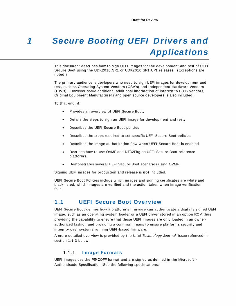
1 Secure Booting UEFI Drivers and Applications
This document describes how to sign UEFI images for the development and test of UEFI Secure Boot using the UDK2010.SR1 or UDK2010.SR1.UP1 releases. (Exceptions are noted.)
The primary audience is devlopers who need to sign UEFI images for development and test, such as Operating System Vendors (OSV’s) and Independent Hardware Vendors (IHV’s). However some additional additional information of interest to BIOS vendors, Original Equipment Manufacturers and open source developers is also included.
To that end, it:
• Provides an overview of UEFI Secure Boot,
• Details the steps to sign an UEFI image for development and test,
• Describes the UEFI Secure Boot policies
• Describes the steps required to set specific UEFI Secure Boot policies
• Describes the image authorization flow when UEFI Secure Boot is enabled
• Decribes how to use OVMF and NT32Pkg as UEFI Secure Boot reference platforms.
• Demonstrates several UEFI Secure Boot scenarios using OVMF.
Signing UEFI images for production and release is not included.
UEFI Secure Boot Policies include which images and signing certificates are white and black listed, which images are verified and the action taken when image verification fails.
1.1 UEFI Secure Boot Overview UEFI Secure Boot defines how a platform’s firmware can authenticate a digitally signed UEFI image, such as an operating system loader or a UEFI driver stored in an option ROM thus providing the capability to ensure that those UEFI images are only loaded in an owner-authorized fashion and providing a common means to ensure platforms security and integrity over systems running UEFI-based firmware.
A more detailed overview is provided by the Intel Technology Journal issue refenced in section 1.1.3 below.
1.1.1 Image Formats UEFI images use the PE/COFF format and are signed as defined in the Microsoft * Authenticode Specification. See the following specifications:
• Microsoft Portable Executable and Common Object File Format Specification,
http://www.microsoft.com/whdc/system/platform/firmware/PECOFF.mspx
• Windows Authenticode Portable Executable Signature Format, http://www.microsoft.com/whdc/winlogo/drvsign/Authenticode_PE.mspx
1.1.2 UEFI Secure Boot Policy
UEFI Secure Boot was designed with the following goals: • Allow the platform owner to check the integrity and security of a given UEFI image
ensuring that the image is only loaded in an approved manner. • Allow the platform owner to manage the platform’s security policy as defined by the
UEFI Secure Boot authenticated variables described below. UEFI Secure Boot is controlled by a set of UEFI Authenticated Variables which specify the UEFI Secure Boot Policy. This policy includes which images and certificates are contained in the white list (a.k.a the authorized signature database) and the black list (a.k.a the forbidden signature database). UEFI Authenticated Variables are defined in the UEFI 2.3.1C Specification and described in section 1.2 below.
1.1.3 Additional Information Additional information on UEFI Secure Boot and Authenticated Variables can be found in the following documents:
• Intel Technology Journal, Volume 15, Issue 1, 201, UEFI Today: Bootstrapping the Continuum, UEFI Networking and Pre-OS Security, page 80 at http://www.intel.com/technology/itj/2011/v15i1/pdfs/Intel-Technology-Journal-Volume-15-Issue-1-2011.pdf.
• UEFI 2.3.1C Specification : Sections 7.2 (Variable Services) and Sections 27.2 through 27.8 (Secure Boot) of the at www.uefi.org.
Please note that the use of the “Secure Boot” in Section 27.1 is an overloaded usage that is unrelated to “Secure Boot” as used in this document.
• Beyond BIOS: Developing with the Unified Extensible Firmware Interface, 2nd Edition, Vincent Zimmer, ISBN 13 978-1-934053-29-4, Chapter 10 – Platform Security and Trust, www.intel.com/intelpress.
• Harnessing the UEFI Shell, Moving the platform beyond DOS, Michael Rothman www.intel.com/intelpress. Appendix A - Security Considerations.
• Windows Hardware Certification Requirements December, 2011. http://msdn.microsoft.com/library/windows/hardware/hh748188
1.1.4 Document Precedence
Should any information provided in this document conflict with information contained in the UEFI 2.3.1C Specification , the UEFI 2.3.1C Specification takes precedence unless explicitly noted.
Draft for Review
1.2 UEFI Secure Boot’s Authenticated Variables
1.2.1 Overview of Authenticated Variables
The UEFI Authenticated Variable Service is defined as an enhancement to the UEFI Variable Serice. It provides a means to ensure the integrity of specified variables by prepending authentication data, shown as EFI_VARIABLE_AUTHENTICATION in the figure below. This authentication data is defined in chapter 3 of the UEFI 2.3.1C Specification .
If a variable’s EFI_VARIABLE_AUTHENTICATED_WRITE_ACCESS bit is set when the SetVariable function is called, both the identity of the operator and integrity of data will be authenticated before the variable is written into storage.
Since confidentiality was not a design goal, there is no verification of data that is subsequently read using the GetVariable function. Therefore anyone can read authenticated variables, but only parties possessing the correct key-pair can write or update authenticated variables.
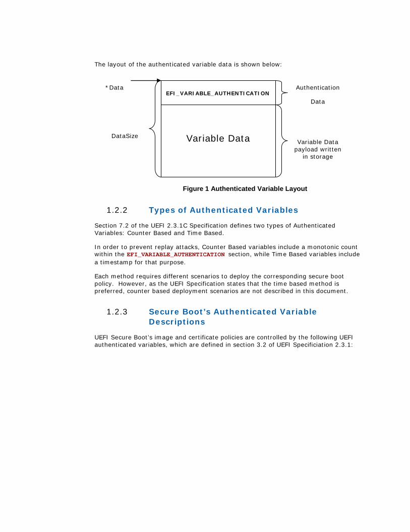
The layout of the authenticated variable data is shown below:
Figure 1 Authenticated Variable Layout
1.2.2 Types of Authenticated Variables
Section 7.2 of the UEFI 2.3.1C Specification defines two types of Authenticated Variables: Counter Based and Time Based.
In order to prevent replay attacks, Counter Based variables include a monotonic count within the EFI_VARIABLE_AUTHENTICATION section, while Time Based variables include a timestamp for that purpose.
Each method requires different scenarios to deploy the corresponding secure boot policy. However, as the UEFI Specification states that the time based method is preferred, counter based deployment scenarios are not described in this document.
1.2.3 Secure Boot’s Authenticated Variable Descriptions
UEFI Secure Boot’s image and certificate policies are controlled by the following UEFI authenticated variables, which are defined in section 3.2 of UEFI Specificiation 2.3.1:
Variable Data
EFI_VARIABLE_AUTHENTICATION
DataSize
*Data Authentication
Data
Variable Data payload written
in storage
Draft for Review
• Platform Key (PK) - The platform key establishes a trust relationship between the platform owner and the platform firmware. The platform owner enrolls the public half of the key (PKpub) into the platform firmware. The platform owner can later use the private half of the key (PKpriv) to change platform ownership or to enroll a Key Exchange Key. Enrolling a PK enables UEFI Secure Boot and deleting the PK disables it. For UEFI 2.3.1, the recommended Platform Key format is RSA-2048.
• Key Exchange Key (KEK) - The Key exchange keys establish a trust relationship between the operating system and the platform firmware. The KEK determines who is authorized to update the DB and DBX described below. The public part of the key (KEKpub) is enrolled into the platform firmware. Each operating system (and potentially, each third party application which need to communicate with platform firmware) can later use the private half of the key (KEKpriv) to communication with firmware in trusted manner. For UEFI 2.3.1, the recommended Key Exchange Key format is RSA-2048.
• Authorized Signature Database (DB) - This database contains authorized signing certificates and digital signatures. An image signed with a certificate enrolled in DB (or KEK) or whose digital signature is enrolled in DB is authorized to execute. DB is the white list.
• Forbidden Signature Database (DBX) - This database contains forbidden certificates and digital signatures. An image signed with a certificate enrolled in DBX or whose digital signature is enrolled in DBX, is never allowed to run. DBX is the black list.
• Setup Mode - When Setup Mode is null, no Platform Key is enrolled and the platform is said to be operating in setup mode. While in setup mode, the platform firmware does not authenticate images and secure boot policy can be configured by writing the PK, KEK, DB and DBX variables. When Setup Mode is not null, a Platform Key is enrolled and the platform is operating in User Mode. User Mode requires that all executables be authenticated before they are permitted to run.
• SecureBoot – When set (1), the platform is operating in secure boot mode and performs image verification based on the data stored in KEK, DB and DBX.
1.3 Image Authorization Flow The authorization process by which an unknown UEFI image might be authorized to run during LoadImage is described below. For more information, see Section 27.7 of the UEFI specification.
During initialization of an UEFI executable based on the secure boot policy, the Boot Manager decides whether the UEFI executable should be initialized and run. Verification success means the executable passed authentication which means that either its signing certificate or signature was found in the authorized signature database and was not found in the forbidden signature database. Otherwise, verification fails.
The verification steps for both unsigned images and images signed as described in section 1.4 are described below using the following definitions:
• Signature – is the SHA256 hash of the PE/COFF image.
• Certificate – is the image’s Authenticode certificate containing the public key used to sign the image.
• Certificate Authorized
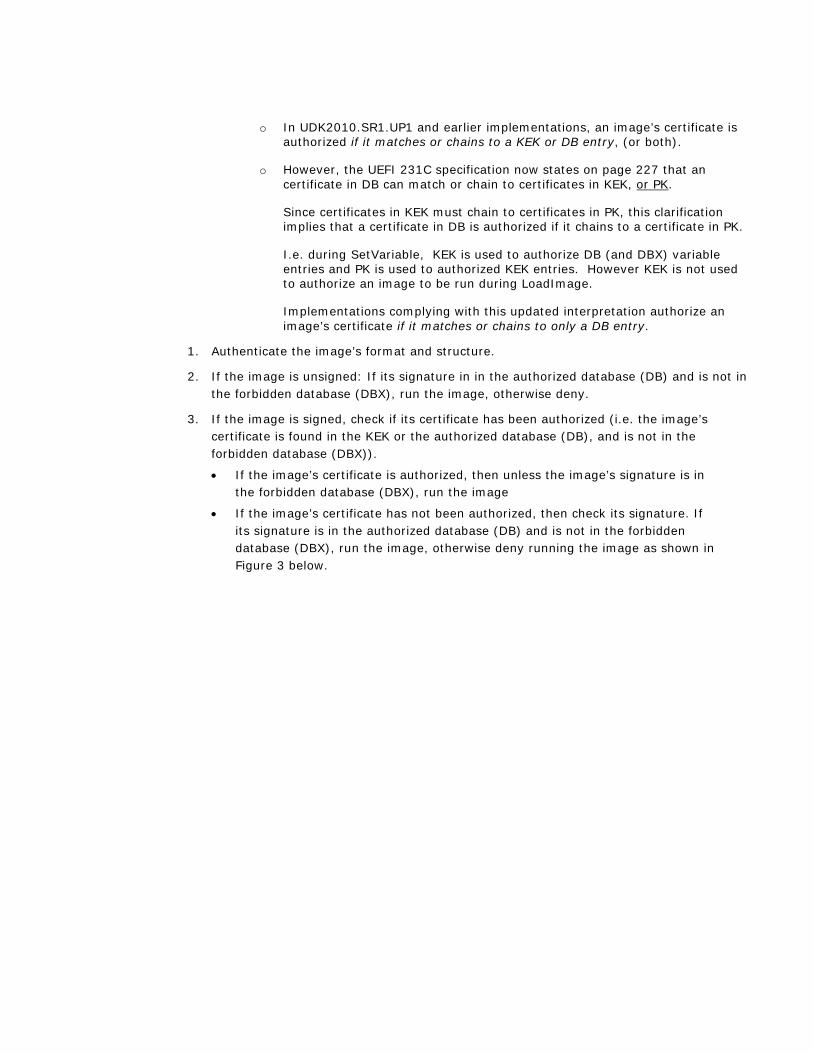
o In UDK2010.SR1.UP1 and earlier implementations, an image’s certificate is authorized if it matches or chains to a KEK or DB entry, (or both).
o However, the UEFI 231C specification now states on page 227 that an certificate in DB can match or chain to certificates in KEK, or PK.
Since certificates in KEK must chain to certificates in PK, this clarification implies that a certificate in DB is authorized if it chains to a certificate in PK.
I.e. during SetVariable, KEK is used to authorize DB (and DBX) variable entries and PK is used to authorized KEK entries. However KEK is not used to authorize an image to be run during LoadImage.
Implementations complying with this updated interpretation authorize an image’s certificate if it matches or chains to only a DB entry.
1. Authenticate the image’s format and structure.
2. If the image is unsigned: If its signature in in the authorized database (DB) and is not in the forbidden database (DBX), run the image, otherwise deny.
3. If the image is signed, check if its certificate has been authorized (i.e. the image’s certificate is found in the KEK or the authorized database (DB), and is not in the forbidden database (DBX)).
• If the image’s certificate is authorized, then unless the image’s signature is in the forbidden database (DBX), run the image
• If the image’s certificate has not been authorized, then check its signature. If its signature is in the authorized database (DB) and is not in the forbidden database (DBX), run the image, otherwise deny running the image as shown in Figure 3 below.
Draft for Review
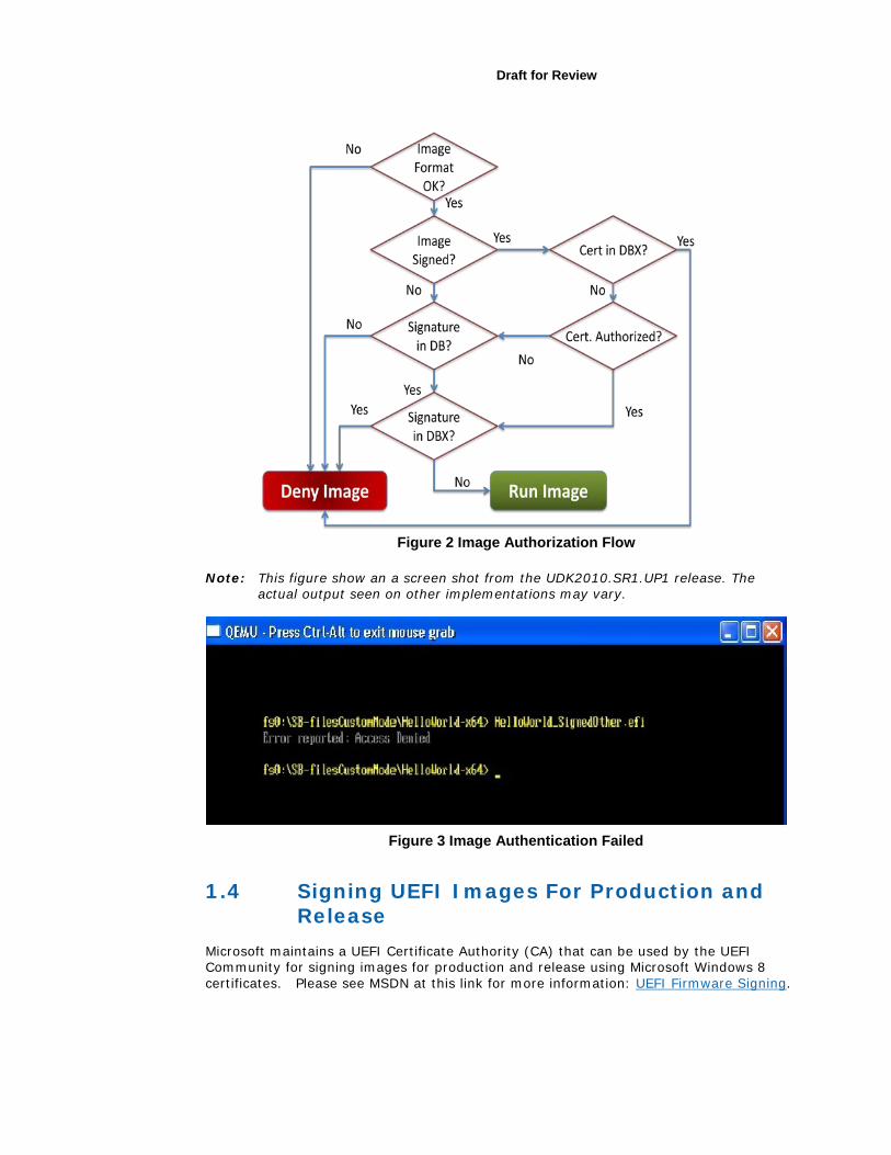
Figure 2 Image Authorization Flow
Note: This figure show an a screen shot from the UDK2010.SR1.UP1 release. The actual output seen on other implementations may vary.
Figure 3 Image Authentication Failed
1.4 Signing UEFI Images For Production and Release
Microsoft maintains a UEFI Certificate Authority (CA) that can be used by the UEFI Community for signing images for production and release using Microsoft Windows 8 certificates. Please see MSDN at this link for more information: UEFI Firmware Signing.

1.5 Signing UEFI Images For Development and Test
This section provides details on how to sign UEFI images for development and test using Microsoft Windows * hosted Tools (Section 1.5.1) or Linux Hosted Tools (Section 1.5.3) as well as how to set up a system to dual boot Microsoft Windows 8 * and Linux using a PK generated with openssl and “off the shelf” KEK & DB certificates (Section 1.5.2).
For background information about signing a UEFI executable per the Microsoft Authenticode Specification, please refer to:
• http://msdn.microsoft.com/en-us/library/ms537359.aspx
• Harnessing the UEFI Shell, Moving the platform beyond DOS, Michael Rothman www.intel.com/intelpress. See Appendix A - Security Considerations.
• The PE/COFF and Authenticode Specifications referenced in section 1.1.1.
See the "Practical UEFI Secure Boot" video series on the Intel YouTube channel, which shows how to setup a system to dual boot Microsoft Windows 8* & Ubuntu* Linux with UEFI Secure Boot enabled.
1.5.1 Microsoft Windows * Hosted Signing Tools
This section:
• Lists a set of Microsoft Windows* tools that can be used to sign UEFI images
• Lists where to obtain the tools.
• Describes how to generate the required keys and certificates.
• Details how to use those keys and certificates to sign an image.
When signing executables using the Microsoft* Authenticode Sign Tool, the digital signature is generated with the certificate type WIN_CERT_TYPE_PKCS_SIGNED_DATA which is defined in the UEFI 2.3.1C Specification .

Draft for Review
1.5.1.1 Required Tools
This section lists one set of the tools that satisfy the signing scenario detailed in sections 1.4.1.5 and 1.4.1.6.
The following tools are required by this scenario:
• Microsoft* MakeCert – creates private keys (.pvk files) and X509 certificates (.cer files).
• Microsoft* Pvk2Pfx – converts .pvk files to.pfx files
• Microsoft* SignTool – signs a PE/COFF image such as a .efi file using the keys and certificates created with the makecert and pvk2pfx tools.
Additional usage information for Micrsoft tools can be found on MSDN (www.msdn.microsoft.com).
Note: The pfx, pvk file formats are described in 1.4.1.3 below.
Note: These tools may require administrator privileges.
1.5.1.2 Getting the Tools
At this time, the most current version of these three tools are all provided in the Windows 8 Consumer Preview SDK available at: http://msdn.microsoft.com/en-us/windows/hardware/hh852363 in the C:\Program Files (x86)\Windows Kits\8.0\bin\... directory.
Note: These tools must be run from their location in the SDK as they require additional DLL and manifest files from that location. I.e. the .exe’s should not be copied to and run from another location.
Note: Older versions should be avoided.
1.5.1.3 File Format Details
This section provides details on the file formats used above:
• .pvk is a Microsoft private key file format.
• .cer is a X509 certificate format using ASN.1 DER encoding.
• .pfx format is defined by the PKCS#12 standard (http://www.rsa.com/rsalabs/node.asp?id=2138 )
1.5.1.4 Files Used in this Document
The scenario used in subsequent sections references the following files.
• Driver being signed - MyDriver.efi
• Root Certificate. Use for development and test only.

• TestRoot.cer - Root certificate in X509 format.
• TestRoot.pvk - The Root Certificate’s private key in Microsoft PVK format. Has a password.
• TestRoot.pfx - Root Certificate’s private key in PKCS#12 format.
• Sub-Certificate. Signed by the root certificate. Used to sign the driver. Will be enrolled in the KEK variable.
• TestSub.cer – Sub-certificate in X509 format. Will be enrolled as KEK.
• TestSub.pvk - Sub-Certificate’s private key in Microsoft PVK format. Has a password.
• TestSub.pfx - Sub-Certificate’s private key in PKCS#12 format.
1.5.1.5 Creating Keys and Certificates for Development and Test
This section describes how to create the keys and certificates required to sign a PE/COFF image for development and test purposes using the Microsoft* SignTool. It may also be possible to sign development and test images using other signing tools or a Certificate Authority (CA) provided by an OSV or trusted third party.
Note: These self generated keys and self signed certificates are intended for temporary use during development and test only and not for production use.
Note: The signing of production images requires advanced key management practices to ensure the security of the private keys and is beyond the scope of this document.
Note: The example commands below show x64 executables from the default install path of the Windows 8 Consumer Preview SDK.
Note: The following Command Line Prompt instructions must be run in Administrator mode under Windows 7*.
The example detailed in this document uses a two level certificate chain
The steps are:
1. Generate a self signed certificate as the Root Certificate.
2. Use the Root Certificate to sign a Sub-Certificate (a.k.a. child certificate)
1. Generate a self-signed certificate. The certificate is used as the Root Certificate and
is named TestRoot.cer. It is un-trusted, and intended only for development and test use. Its related private key file is TestRoot.pvk.
The Command line under DOS environment is:
Draft for Review
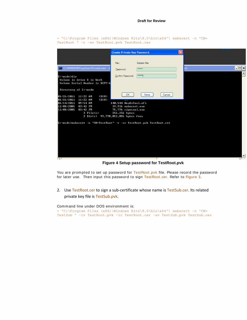
> "C:\Program Files (x86)\Windows Kits\8.0\bin\x64"\ makecert -n "CN= TestRoot " -r -sv TestRoot.pvk TestRoot.cer
Figure 4 Setup password for TestRoot.pvk
You are prompted to set up password for TestRoot.pvk file. Please record the password for later use. Then input this password to sign TestRoot.cer. Refer to Figure 3.
2. Use TestRoot.cer to sign a sub-certificate whose name is TestSub.cer. Its related
private key file is TestSub.pvk.
Command line under DOS environment is: > "C:\Program Files (x86)\Windows Kits\8.0\bin\x64"\ makecert -n "CN= TestSub " -iv TestRoot.pvk -ic TestRoot.cer -sv TestSub.pvk TestSub.cer
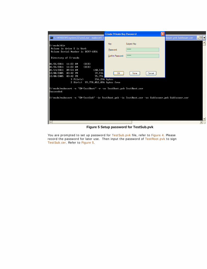
Figure 5 Setup password for TestSub.pvk
You are prompted to set up password for TestSub.pvk file, refer to Figure 4. Please record the password for later use. Then input the password of TestRoot.pvk to sign TestSub.cer. Refer to Figure 5.
Draft for Review
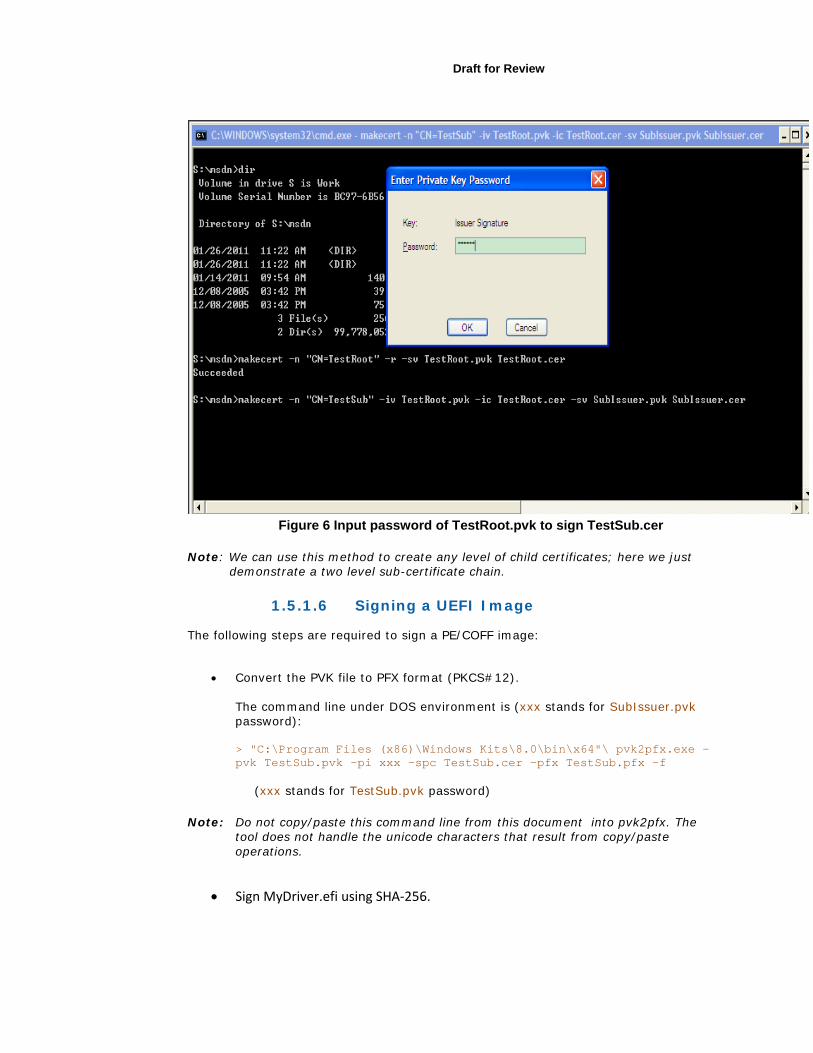
Figure 6 Input password of TestRoot.pvk to sign TestSub.cer
Note: We can use this method to create any level of child certificates; here we just demonstrate a two level sub-certificate chain.
1.5.1.6 Signing a UEFI Image
The following steps are required to sign a PE/COFF image:
• Convert the PVK file to PFX format (PKCS#12).
The command line under DOS environment is (xxx stands for SubIssuer.pvk password): > "C:\Program Files (x86)\Windows Kits\8.0\bin\x64"\ pvk2pfx.exe –pvk TestSub.pvk –pi xxx –spc TestSub.cer –pfx TestSub.pfx –f
(xxx stands for TestSub.pvk password)
Note: Do not copy/paste this command line from this document into pvk2pfx. The tool does not handle the unicode characters that result from copy/paste operations.
• Sign MyDriver.efi using SHA-256.

Note: signtool modifies the unsigned driver by adding the signature. If you wish to maintain a copy of the unsigned driver, first copy it to another name.
The command line under DOS environment is:
> "C:\Program Files (x86)\Windows Kits\8.0\bin\x64"\ SignTool.exe sign /ac TestSub.cer /f TestSub.pfx /p xxx /fd sha256 MyDriver.efi
(xxx stands for TestSub.pvk password)
Note: All images that execute once Secure Boot is enabled must be signed (i.e. once PK has been enrolled and the platform is in User Mode as shown in Error! Reference source not found.Figure 6 Error! Reference source not found.below.
1.5.2 Dual Booting Windows 8 * and Ubuntu Linux
An alternative to the steps detailed above is to generate a PK using OpenSSL. This PK can then be used with the Microsoft KEK, Windows DB and UEFI DB to dual boot Microsoft Windows 8 * and various Linux distributions.
The "Practical UEFI Secure Boot" video series on the Intel YouTube channel, shows how to setup a system to dual boot Microsoft Windows 8* & Ubuntu* Linux with UEFI Secure Boot enabled using this PK.
1.5.2.1 Generating PK with Openssl
The openssl commands to generate a PK and convert it into the required format are:
openssl req -new -x509 -newkey rsa:2048 -keyout PK.key -out PK.crt
openssl x509 -in PK.crt -out PK.cer -outform DER
1.5.2.2 KEK and DB Certificates for Secure Booting Microsoft Windows 8 * and various Linux Distributions
The KEK and DB certificates needed to secure boot Microsoft Windows 8 * and various Linux distributions are:
• Key Exchange Key (KEK)
http://www.microsoft.com/pkiops/certs/MicCorKEKCA2011_2011-06-24.crt
There are two DB entries - one for Windows and one for the UEFI Certificate
Authority (CA).
• Windows DB http://www.microsoft.com/pkiops/certs/MicWinProPCA2011_2011-10-
19.crt
Draft for Review
• UEFI DB http://www.microsoft.com/pkiops/certs/MicCorUEFCA2011_2011-06-
27.crt
The UEFI DB entry allows binaries signed against the UEFI certificate authority to run when secure boot is enabled. This includes UEFI drivers, option ROMs and various Linux bootloaders. The Microsoft DB entries are specific to Microsoft Windows 8.
The GUID associated with these certificates is 77fa9abd-0359-4d32-bd60-28f4e78f784b.
1.5.3 Linux Hosted Signing Tools
Linux hosted signing tools are currently being developed. For the latest information, please see: https://sourceforge.net/apps/mediawiki/tianocore/index.php?title=SecurityPkg#Signing_Tools.
1.5.4 Images with Multiple Signatures
Microsoft* SignTool and the image verification algorithm in UDK2010.SR1.UP1 only support images containing one certificate. However the Authenticode and the UEFI 2.3.1C Specifications do not preclude images containing a list of signatures. Other SignTools are emerging that can create images with multiple signatures.
For the latest information, please see: https://sourceforge.net/apps/mediawiki/tianocore/index.php?title=SecurityPkg#Images with Multiple Signatures .
1.5.5 Image Verification Rules
All signing tools must comply with the Microsoft* Authenticode and PE/COFF Specifications referenced above.
A summary of the rules detailed in those specifications is:
• The image’s PE/COFF sections must be ordered. That is each section’s PointerToRawData should be larger than the previous section’s PointerToRawData.
• The image’s PE/COFF sections must be adjacent. That is there should be no gaps when the sections are loaded into memory per their VirtualSize and VirtualAddress parameters and padded as defined in the PE/COFF Specification.
• The size of the unsigned .efi image file must comply with the Autheticode hashing algorithm. This can be summarized as follows:
a. The actual size of the unsigned .efi image file, as obtained by the dir or ls commands or file properties, should equal
b. The sum of:
1. The PE/COFF OptionalHeader.SizeOfHeaders

2. The sum of each section’s SizeOfRawData.
Note: The value of the PE/COFF OptionalHeader.SizeOfImage field may be different from the file size with some tool chains.
The presence of any other data in the .efi file will cause the image to fail Authenticode verification.
On Micrsoft Windows * systems, these values can be obtained using: link –dump –headers file.efi
On Linux systems, objdump –x file.efi
shows the section’s VirtualSize but not the section’s SizeOfRawData, which is required for this calculation.
1.6 Convert the Signed Driver to a .rom File Chapter 32 of the Drivers Writers Guide for UEFI 2.3 (DWG) describes ways to distribute UEFI drivers. If the signed driver will be installed in a PCI card option rom, it must be converted from an .efi file to a .rom file.
The UEFI DWG describes multiple methods to do this conversion. However, the EfiRom utility will lilely be the most common method used for signed images because the signing needs to occur after the EDK II build and before packaging into an Option ROM. The EDK II build system does not have the ability to automatically sign UEFI Drivers before packaging them into an Option ROM. This process is described in section 18.7.1 of the DWG.
The EfiRom utility binary can be found in the BaseTools/Bin/Win32 directory in the EDK II workspace.
This example creates MyDriver.bin from the MyDriver.efi that was just signed:
>EfiRom -f 0x1013 -i 0x00b8 -e MyDriver.efi
Where –f is the VendorId and –I is the DeviceId.
The Example shows the values for the Cirrus Logic 5446 device included in the OvmfPkg.
1.7 Install the Signed Driver If the signed driver will be installed in a PCI card option rom, next flash the PCI card as described by the card vendor.
If the signed driver will be dristributed in the EFI System Partition, it is ready for deployment.

Draft for Review
1.8 Adding a Signed Driver to the Boot Sequence
The signed driver is added to the boot sequence in setup’s Boot Maintenance Manager by selecting Driver Options and then Add Driver Option Using File.
1.9 Deploying Secure Boot Image and Certificate Policy
This section describes how to deploy Secure Boot Image and Certificate Policy using the Secure Boot Custom Mode Setup feature.
Note: This feature was not contained in UDK2010.SR1 release but was added in EDK II check in r13146 and will be available in future UDK releases. The current UDK2010.SR1.UP1 contains this feature.
Other methods to deply Secure Boot Policy using bios vendor or operating system vendor specific tools are not discussed in this document.
It should be noted that Secure Boot Custom Mode Setup is not required by the UEFI 2.3.1C Specification but is required by the Windows Hardware Certification Requirements December, 2011. http://msdn.microsoft.com/library/windows/hardware/hh748188
The Secure Boot Image and Certificate Policy is specified by specifying the PK and KEK and adding authorized certificates and image signatures to the Authorized Signature Database variable (DB) and forbidden certificates and image signatures to the Forbidden Signature Database variable (DBX). Secure Boot Custom Mode provides setup screens for this purpose
1.9.1 Secure Boot Setup & User Mode
Section 27.5 of the UEFI 2.3.1C Specification defines Setup and User mode.
• Setup Mode - occurs when no Platform Key (PK) is enrolled. In this mode, the PK, KEK, DB and DBX variables can be written without authorization.
• User Mode - occurs after a PK is enrolled and continues until the PK is cleared. While in User Mode, the Secure Boot Policy is enforced.
The current mode can be obtained by reading the SetupMode variable as described in UEFI 2.3.1C Section 3.2 where a value of 1 indicates SetupMode and a value of 0 indicates User Mode.
The code fragment below shows an example that checks the value of SetupMode using the GetEfiGlobalVariable() library function which uses the EFI_GLOBAL_VARIABLE GUID. This function is provided in MdePkg\Library\UefiLib\UefiLib.c.
#include <Uefi.h> #include <Library/UefiLib.h>
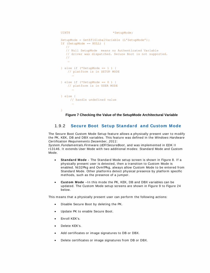
UINT8 *SetupMode; SetupMode = GetEfiGlobalVariable (L”SetupMode”); If (SetupMode == NULL) {
// // Null SetupMode means no Authenticated Variable // driver was dispatched. Secure Boot is not supported. // …
} else if (*SetupMode == 1 ) { // platform is in SETUP MODE … } else if (*SetupMode == 0 ) {
// platform is in USER MODE … } else { // handle undefined value … }
Figure 7 Checking the Value of the SetupMode Architectural Variable
1.9.2 Secure Boot Setup Standard and Custom Mode
The Secure Boot Custom Mode Setup feature allows a physically present user to modify the PK, KEK, DB and DBX variables. This feature was defined in the Windows Hardware Certification Requirements December, 2011: System.Fundamentals.Firmware.UEFISecureBoot, and was implemented in EDK II r13146. It extends User Mode with two additional modes: Standard Mode and Custom Mode.
• Standard Mode - The Standard Mode setup screen is shown in Figure 8. If a physically present user is detected, then a transition to Custom Mode is enabled. Nt32Pkg and OvmfPkg, always allow Custom Mode to be entered from Standard Mode. Other platforms detect physical presence by platform specific methods, such as the presence of a jumper.
• Custom Mode –In this mode the PK, KEK, DB and DBX variables can be updated. The Custom Mode setup screens are shown in Figure 9 to Figure 24 below.
This means that a physically present user can perform the following actions:
• Disable Secure Boot by deleting the PK.
• Update PK to enable Secure Boot.
• Enroll KEK’s.
• Delete KEK’s.
• Add certificates or image signatures to DB or DBX.
• Delete certificates or image signatures from DB or DBX.
Draft for Review
These actions are performed using the setup screens shown in 1.8.4 below.
1.9.3 Using Secure Boot Custom Mode
Before enabling UEFI Secure Boot (by setting the PK) the white and black lists DB & DBX must be set up with authorized and forbidden certificates and signatures.
Recall that DB contains authorized signing certificates and images while DBX contains blocked signing certificates and images. KEK specifies who is authorized to update DB and DBX outside of custom mode setup and so is not required for the development and test signing scenarios described in this document. For certificates, .cer and .der file formats are supported. These are defined in http://www.itu.int/ITU-T/studygroups/com17/languages/X.690-0207.pdf.
1. Configure the authorized signing certificates and image signatures. There are two ways to authorize images to execute when UEFI Secure Boot is enabled:
• All images signed by a signing certificate can be authorized by enrolling the signing certificate: (which is TestSub.cer in this example) in DB.
• Individual images signed by another signing certificate can be authorized without enrolling that signing certificate by enrolling each image’s signature in DB. Unsigned images can be authorized in the same way. (See Figure 21 and Figure 22.)
2. Next configure forbidden signing certificates and image signatures.
• If specific signing certificates or image signatures are to be blacklisted, enroll them in DBX. (See Figure 24.)
3. Finally, enroll PK (TestRoot.cer in this example) to re-enable Secure Boot (See Figure 14).
1.9.4 Secure Boot Custom ModeSetup Screens
This section shows the capabilities provided by the implementation of Secure Boot Custom Mode in EDK II r13146. Other implementations may use different menus.
1.9.4.1 Standard Mode – Secure Boot Configuration
Secure Boot is configured from setup by selecting Device Manager and then Secure Boot Configuration from the Devices List.
This presents the Secure Boot Configuration screen, shown in Figure 8, showing that the system is in Standard Mode (as described in section 0) and that Attempt Secure Boot is enabled .
Note: The “Attempt Secure Boot” entry shows the current state of the SecureBoot UEFI variable and is not related to the Secure Boot Configuration mode. I.e. SecureBoot can be enabled or disabled in either the Standard Secure Boot Configuration Mode or Custom Secure Boot Configuration Mode.
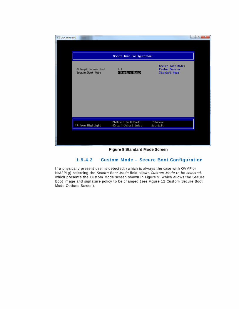
Figure 8 Standard Mode Screen
1.9.4.2 Custom Mode – Secure Boot Configuration
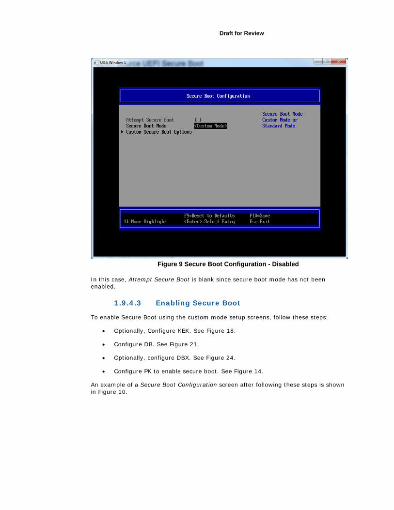
If a physically present user is detected, (which is always the case with OVMF or Nt32Pkg) selecting the Secure Boot Mode field allows Custom Mode to be selected, which presents the Custom Mode screen shown in Figure 9, which allows the Secure Boot image and signature policy to be changed (see Figure 12 Custom Secure Boot Mode Options Screen).
Draft for Review
Figure 9 Secure Boot Configuration - Disabled
In this case, Attempt Secure Boot is blank since secure boot mode has not been enabled.
1.9.4.3 Enabling Secure Boot
To enable Secure Boot using the custom mode setup screens, follow these steps:
• Optionally, Configure KEK. See Figure 18.
• Configure DB. See Figure 21.
• Optionally, configure DBX. See Figure 24.
• Configure PK to enable secure boot. See Figure 14.
An example of a Secure Boot Configuration screen after following these steps is shown in Figure 10.
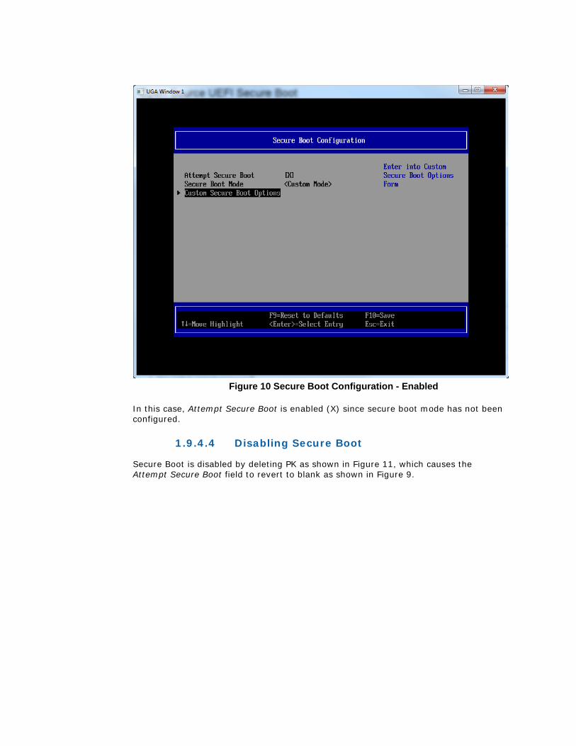
Figure 10 Secure Boot Configuration - Enabled
In this case, Attempt Secure Boot is enabled (X) since secure boot mode has not been configured.
1.9.4.4 Disabling Secure Boot
Secure Boot is disabled by deleting PK as shown in Figure 11, which causes the Attempt Secure Boot field to revert to blank as shown in Figure 9.
Draft for Review
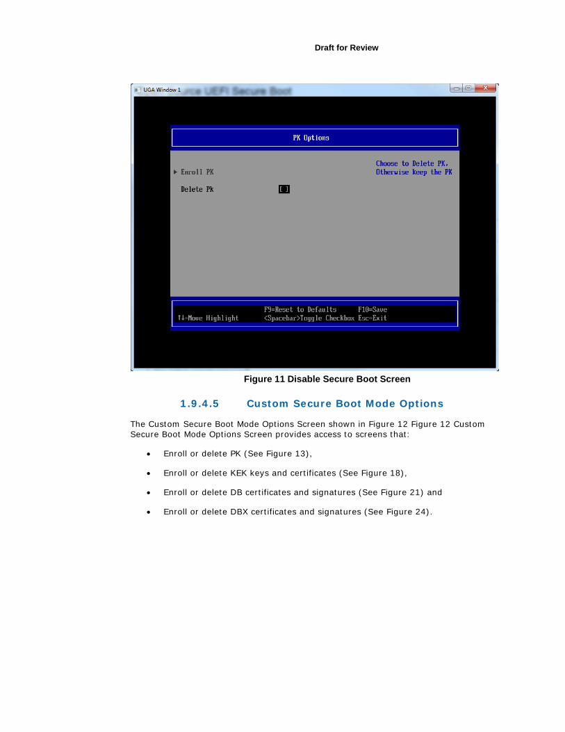
Figure 11 Disable Secure Boot Screen
1.9.4.5 Custom Secure Boot Mode Options
The Custom Secure Boot Mode Options Screen shown in Figure 12 Figure 12 Custom Secure Boot Mode Options Screen provides access to screens that:
• Enroll or delete PK (See Figure 13),
• Enroll or delete KEK keys and certificates (See Figure 18),
• Enroll or delete DB certificates and signatures (See Figure 21) and
• Enroll or delete DBX certificates and signatures (See Figure 24).

Figure 12 Custom Secure Boot Mode Options Screen
1.9.4.6 PK Options
The PK Options entry links to Figure 13 PK Options Screen which allows PK to be enrolled (see Figure 14) or deleted.

Draft for Review
Figure 13 PK Options Screen
1.9.4.7 Enroll PK Using File
Figure 14 Enroll PK Screen allows PK to be loaded from a file, for example from a flash drive.
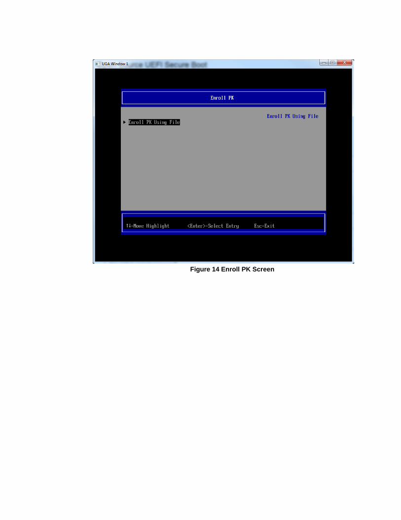
Figure 14 Enroll PK Screen
Draft for Review
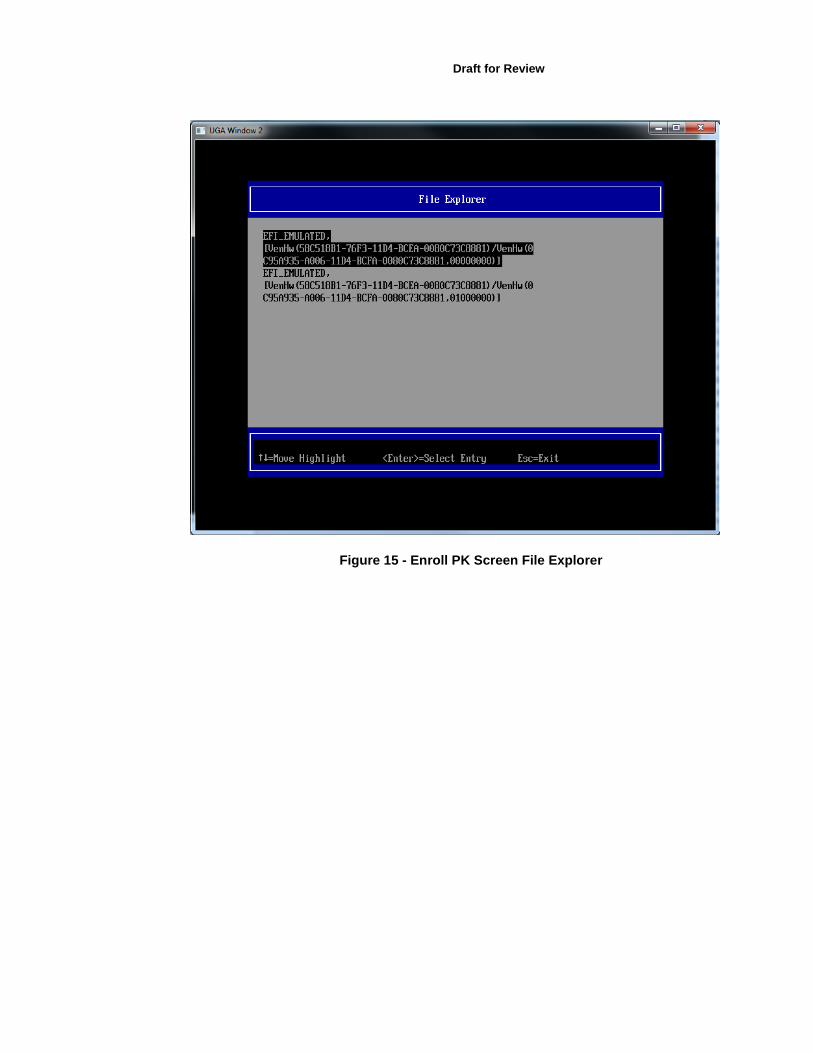
Figure 15 - Enroll PK Screen File Explorer

Figure 16 - Enroll PK file TestRoot.cer

Draft for Review
Figure 17 – Commit to changes
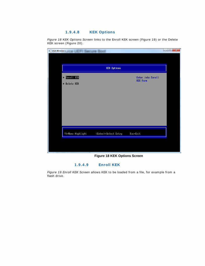
1.9.4.8 KEK Options
Figure 18 KEK Options Screen links to the Enroll KEK screen (Figure 19) or the Delete KEK screen (Figure 20).
Figure 18 KEK Options Screen
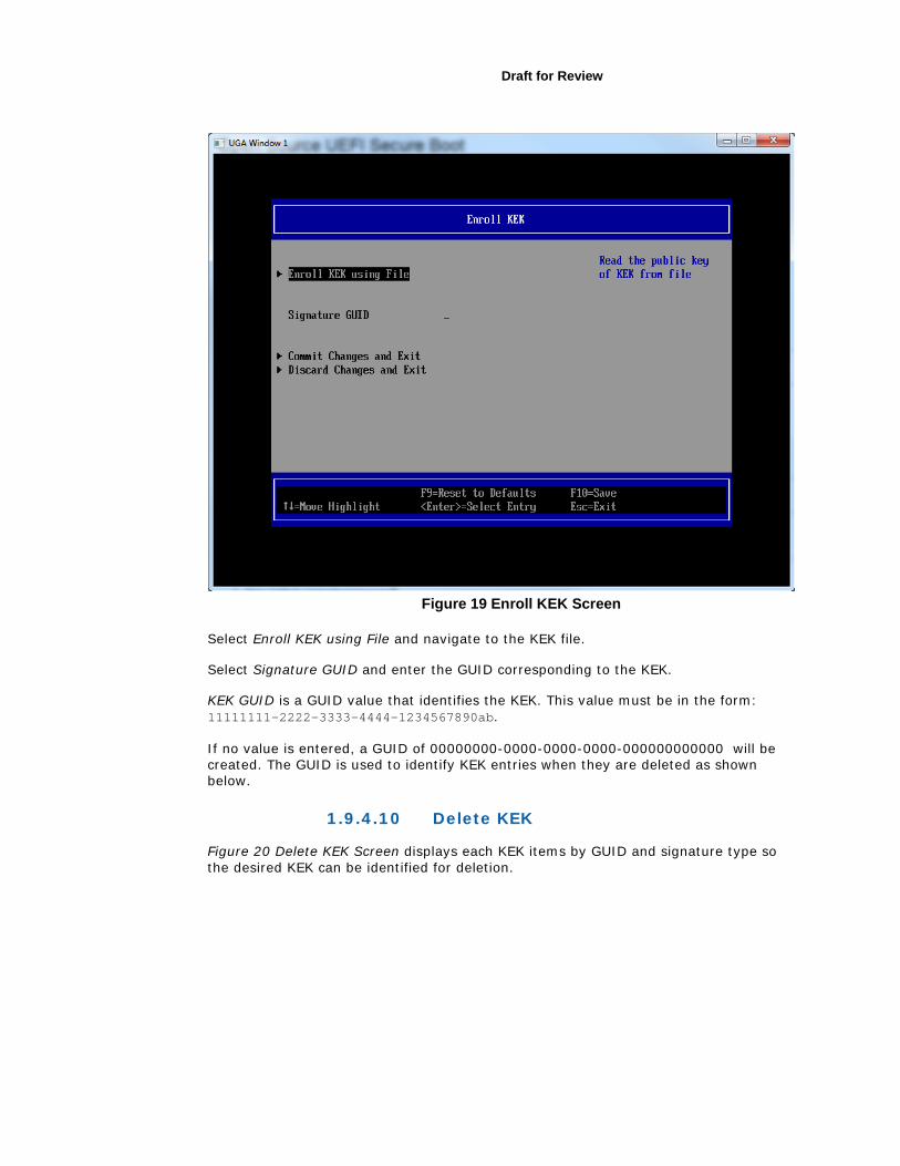
1.9.4.9 Enroll KEK
Figure 19 Enroll KEK Screen allows KEK to be loaded from a file, for example from a flash drive.
Draft for Review
Figure 19 Enroll KEK Screen
Select Enroll KEK using File and navigate to the KEK file.
Select Signature GUID and enter the GUID corresponding to the KEK.
KEK GUID is a GUID value that identifies the KEK. This value must be in the form: 11111111-2222-3333-4444-1234567890ab.
If no value is entered, a GUID of 00000000-0000-0000-0000-000000000000 will be created. The GUID is used to identify KEK entries when they are deleted as shown below.
1.9.4.10 Delete KEK
Figure 20 Delete KEK Screen displays each KEK items by GUID and signature type so the desired KEK can be identified for deletion.
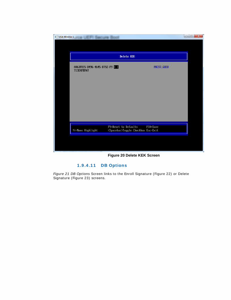
Figure 20 Delete KEK Screen
1.9.4.11 DB Options
Figure 21 DB Options Screen links to the Enroll Signature (Figure 22) or Delete Signature (Figure 23) screens.

Draft for Review
Figure 21 DB Options Screen
1.9.4.12 Enroll Signature
Figure 22 Enroll Signature Screen screen allows image signatures or certificates to be loaded from USB flash drives.
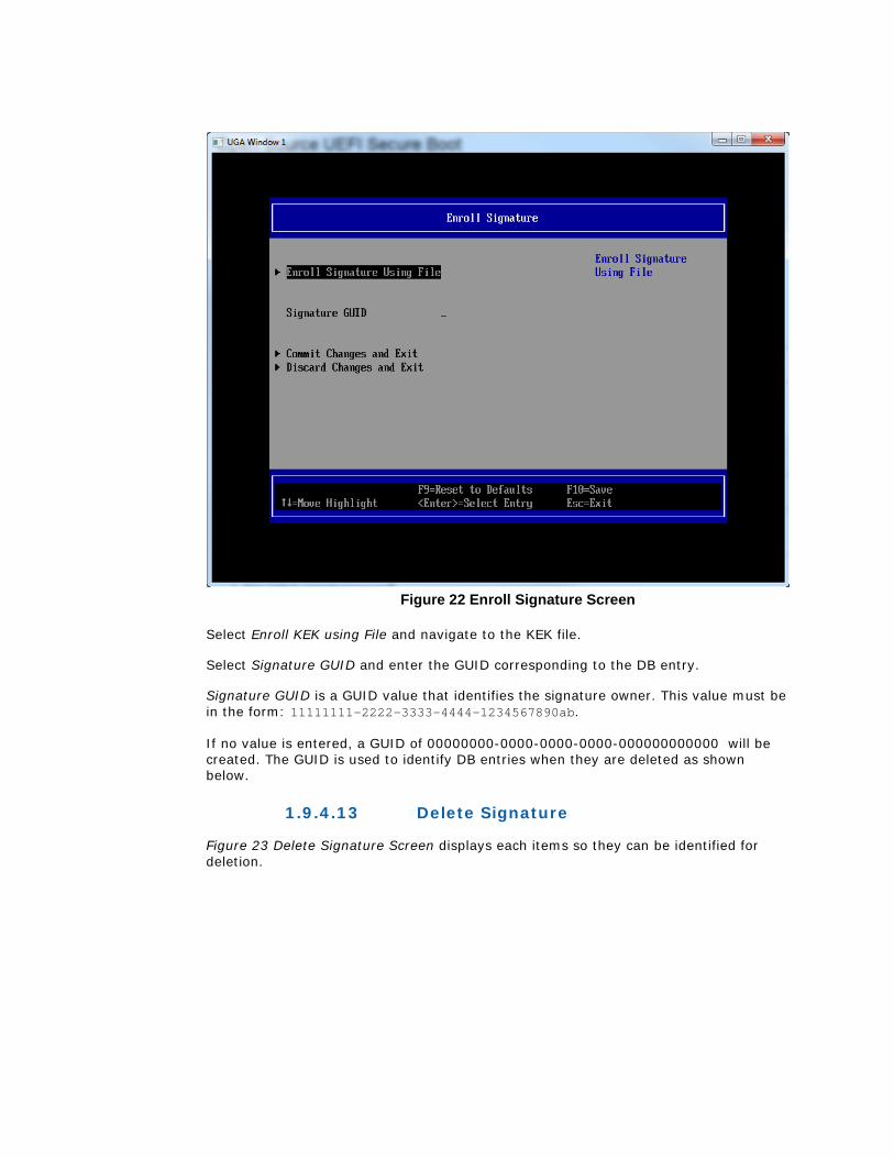
Figure 22 Enroll Signature Screen
Select Enroll KEK using File and navigate to the KEK file.
Select Signature GUID and enter the GUID corresponding to the DB entry.
Signature GUID is a GUID value that identifies the signature owner. This value must be in the form: 11111111-2222-3333-4444-1234567890ab.
If no value is entered, a GUID of 00000000-0000-0000-0000-000000000000 will be created. The GUID is used to identify DB entries when they are deleted as shown below.
1.9.4.13 Delete Signature
Figure 23 Delete Signature Screen displays each items so they can be identified for deletion.

Draft for Review
Figure 23 Delete Signature Screen
1.9.4.14 DBX Options
Figure 24 DBX Options Screen mimics the DB Options Screens …
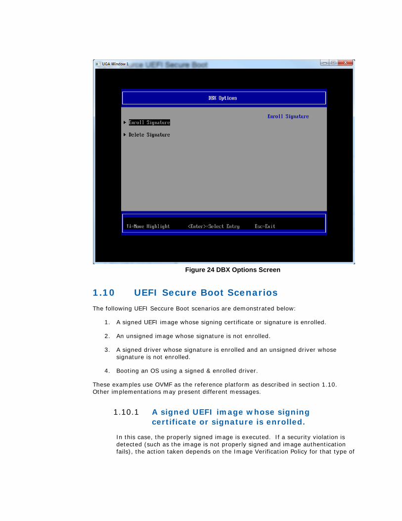
Figure 24 DBX Options Screen
1.10 UEFI Secure Boot Scenarios The following UEFI Seccure Boot scenarios are demonstrated below:
1. A signed UEFI image whose signing certificate or signature is enrolled.
2. An unsigned image whose signature is not enrolled.
3. A signed driver whose signature is enrolled and an unsigned driver whose signature is not enrolled.
4. Booting an OS using a signed & enrolled driver.
These examples use OVMF as the reference platform as described in section 1.10. Other implementations may present different messages.
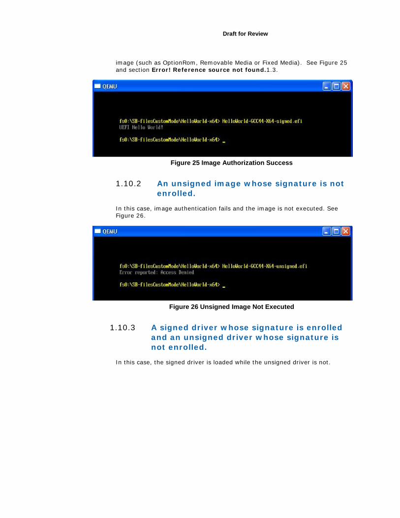
1.10.1 A signed UEFI image whose signing certificate or signature is enrolled.
In this case, the properly signed image is executed. If a security violation is detected (such as the image is not properly signed and image authentication fails), the action taken depends on the Image Verification Policy for that type of
Draft for Review
image (such as OptionRom, Removable Media or Fixed Media). See Figure 25 and section Error! Reference source not found.1.3.
Figure 25 Image Authorization Success
1.10.2 An unsigned image whose signature is not enrolled.
In this case, image authentication fails and the image is not executed. See Figure 26.
Figure 26 Unsigned Image Not Executed
1.10.3 A signed driver whose signature is enrolled and an unsigned driver whose signature is not enrolled.
In this case, the signed driver is loaded while the unsigned driver is not.
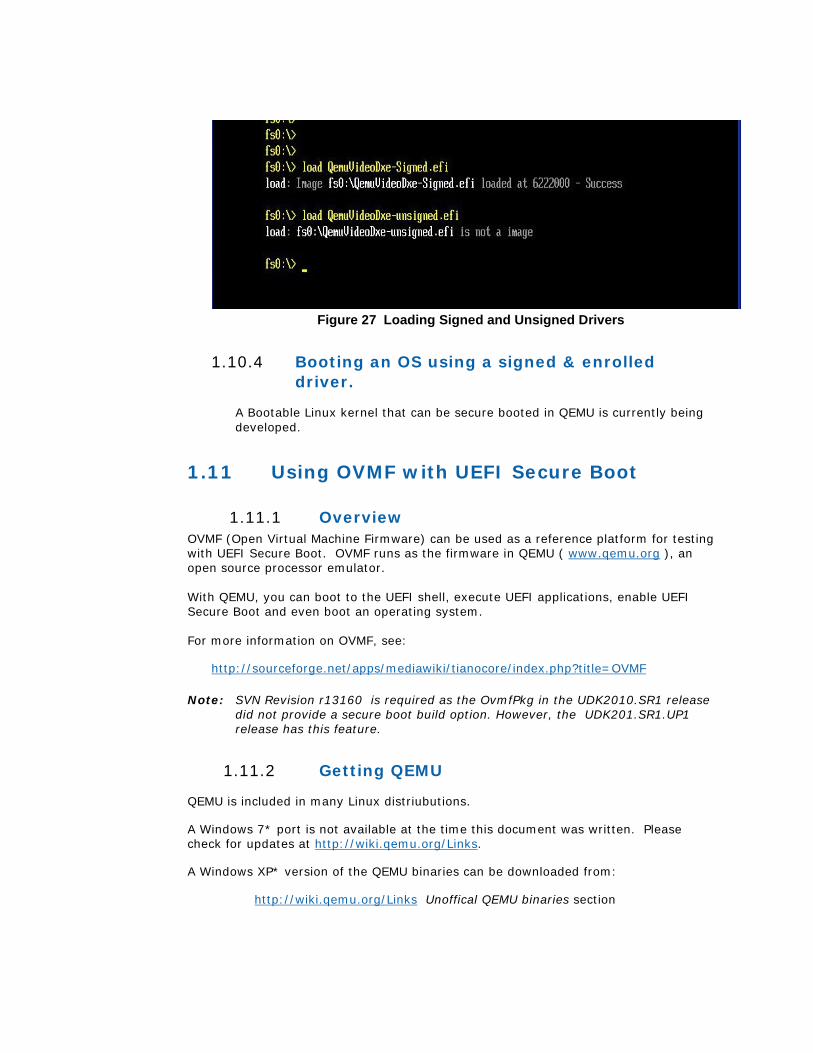
Figure 27 Loading Signed and Unsigned Drivers
1.10.4 Booting an OS using a signed & enrolled driver.
A Bootable Linux kernel that can be secure booted in QEMU is currently being developed.
1.11 Using OVMF with UEFI Secure Boot
1.11.1 Overview OVMF (Open Virtual Machine Firmware) can be used as a reference platform for testing with UEFI Secure Boot. OVMF runs as the firmware in QEMU ( www.qemu.org ), an open source processor emulator. With QEMU, you can boot to the UEFI shell, execute UEFI applications, enable UEFI Secure Boot and even boot an operating system. For more information on OVMF, see:
http://sourceforge.net/apps/mediawiki/tianocore/index.php?title=OVMF
Note: SVN Revision r13160 is required as the OvmfPkg in the UDK2010.SR1 release did not provide a secure boot build option. However, the UDK201.SR1.UP1 release has this feature.
1.11.2 Getting QEMU
QEMU is included in many Linux distriubutions.
A Windows 7* port is not available at the time this document was written. Please check for updates at http://wiki.qemu.org/Links.
A Windows XP* version of the QEMU binaries can be downloaded from:
http://wiki.qemu.org/Links Unoffical QEMU binaries section
Draft for Review
Precompiled Windows versions (≥ 0.9.1), provided by TAKEDA Toshiya
QEMU on Windows Ver 0.13.0 (10/16/2010) http://homepage3.nifty.com/takeda-toshiya/qemu/index.html
Note: This is an older version of QEMU that is missing any updates made since late 2010.
1.11.3 Building OVMF
The EDK II source code that includes OVMF is available at: https://edk2.svn.sourceforge.net/svnroot/edk2/trunk/edk2 .
Instructions for building OVMF can be found at:
http://sourceforge.net/apps/mediawiki/tianocore/index.php?title=How_to_build_OVMF. OVMF can be built in X64, IA32 or IA32X64 architectures.
To summarize, modify Conf/target.txt as shown to build OvmfX64Pkg:
• ACTIVE_PLATFORM = OvmfPkg/OvmfX64Pkg.dsc or
• TARGET_ARCH = X64
Or OvmfIa32X64Pkg:
• ACTIVE_PLATFORM = OvmfPkg/OvmfIa32X64Pkg.dsc
• TARGET_ARCH = IA32 X64
Or OvmfIa32Pkg:
• ACTIVE_PLATFORM = OvmfPkg/OvmfIa32Pkg.dsc
• TARGET_ARCH = IA32
1.11.4 CryptoPkg OpenSslLib Dependency
The Security Package’s Authenticated Variables and Secure Boot features require the cryptographic support provided by OpenSslLib in the CryptoPkg.
OpensslLib is not integrated into the CryptoPkg included in the EDK II repository on Source Forge. Information detailing how to download and install OpenSSL for use in CryptoPkg’s OpenSslLib can be found in CryptoPkg\Library\OpensslLib\ Patch-HOWTO.txt.
1.11.5 Enabling UEFI Secure Boot in OVMF
To enable UEFI Secure Boot in OVMF, the following build command is required:
>build –D SECURE_BOOT_ENABLE
When the build completes, the OVMF image is in the Build directory. For example, if using the UNIXGCC with X64 tool chain, the ovmf.fd image file is located at:

Build/OvmfX64/DEBUG_UNIXGCC/FV/OVMF.fd
1.11.6 Source Level Debugger
Instructions on how to use the UDK2010 Source Level Debugger with OVMF are available at @ http://www.intel.com/content/www/us/en/architecture-and-technology/unified-extensible-firmware-interface/uefi-dev-kit-debugger-tool-manual.html.
1.11.7 Running OVMF with QEMU
QEMU expects the BIOS to be in the bios.bin file and the Video Rom to be in vgabios-cirrus.bin. Both these files should be from the same OVMF platform.
As was described in section 1.10.2 above, QEMU can be run on either Linux or Microsoft Windows XP* systems. However the type of system hosting QEMU has no releationship to the system that hosted the signing tools described in section 1.4 above. That is an image signed with Linux hosted signing tools should be identical to an image signed with Micrsoft Windows* hosted signing tools and vice versa. Furthermore, either image can be run on either QEMU environment.
To run OVMF with QEMU, perform the following steps:
1. Create a ‘run-ovmf’ directory under your build tree to run OVMF with QEMU
bash$ mkdir run-ovmf
2. Copy or link the BIOS and Video Rom Images as shown below:
For Linux hosted QEMU: bash$ cd run-ovmf bash$ ln -s ../Build/OvmfX64/DEBUG_UNIXGCC/FV/OVMF.fv bios.bin bash$ ln -s ../Build/OvmfX64/DEBUG_UNIXGCC/FV/CirrusLogic5446.rom \ vgabios-cirrus.bin
For Microsoft Windows XP * hosted QEMU: > cd run-ovmf >copy ../Build/OvmfX64/DEBUG_UNIXGCC/FV/OVMF.fv bios.bin >copy ../Build/OvmfX64/DEBUG_UNIXGCC/FV/CirrusLogic5446.rom \ vgabios-cirrus.bin
3. Also copy any images, certificates or keys that will be enrolled in PK, KEK, DB or DBX using Secure Boot Custom Mode as described in section 1.8.3 above. Oherwise these files will not be accessible from within QEMU. These are the TestRoot.cer, TestSub.cer and MyDrivers.efi from section 1.4.1.5 and 1.4.1.6 above
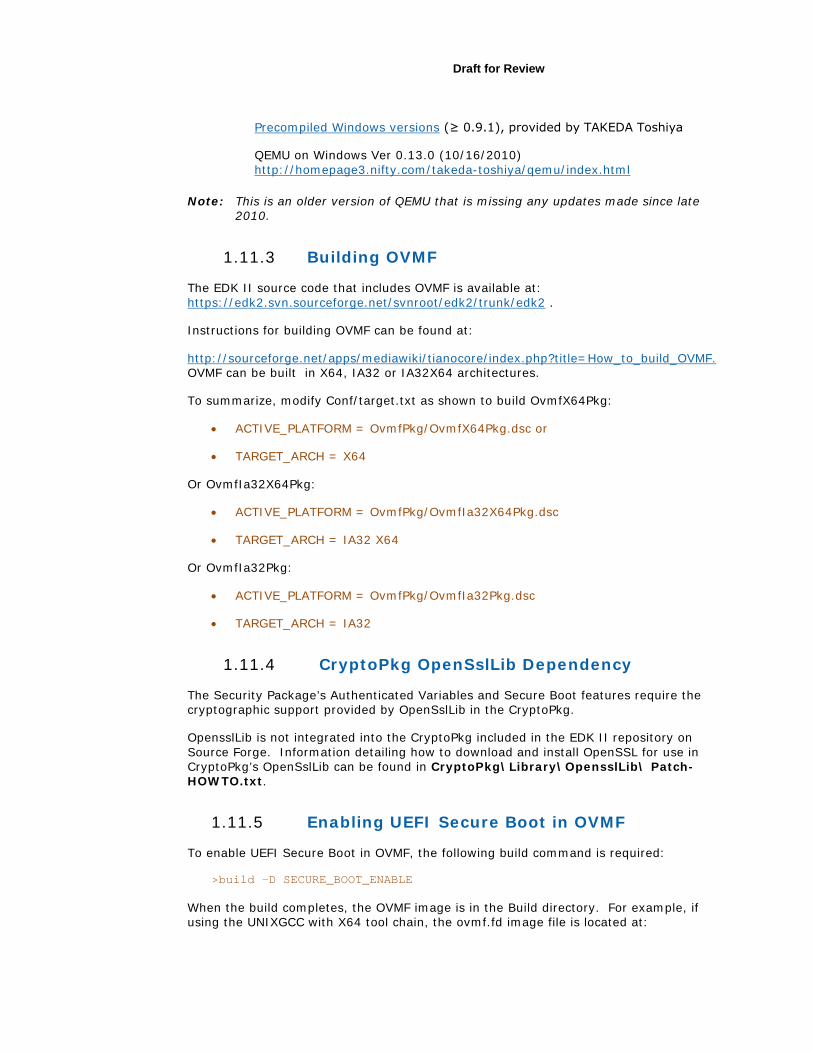
4. Start QEMU with the following command and wait for OVMF to boot to the UEFI shell as shown in Figure 28 below.
bash$ qemu-system-x86_64 -L . -hda fat:.
Draft for Review
Note: This command makes the current directory (run-ovmf in this case) the hard disk used by QEMU. However, QEMU treats this disk as read only so files generated within QEMU are not visible in run-ovmf after QEMU exits.
Figure 28 QEMU Running OVMF
Next select the file system:
Shell> fs0:
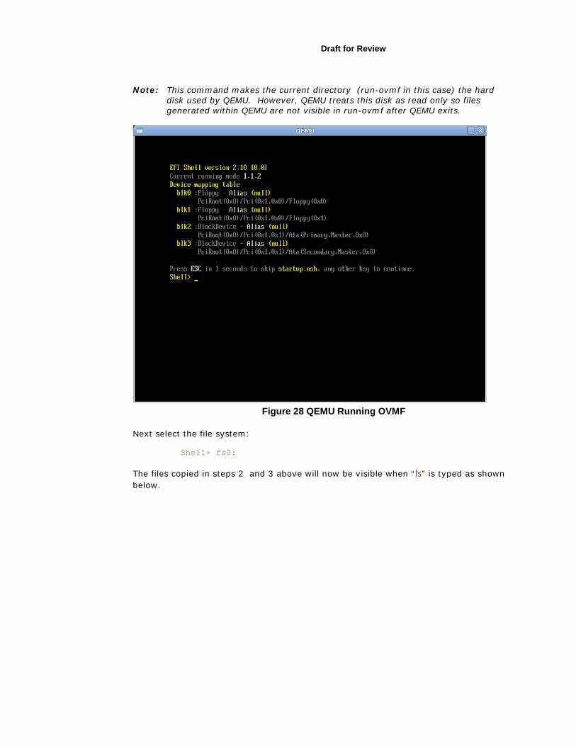
The files copied in steps 2 and 3 above will now be visible when “ls” is typed as shown below.
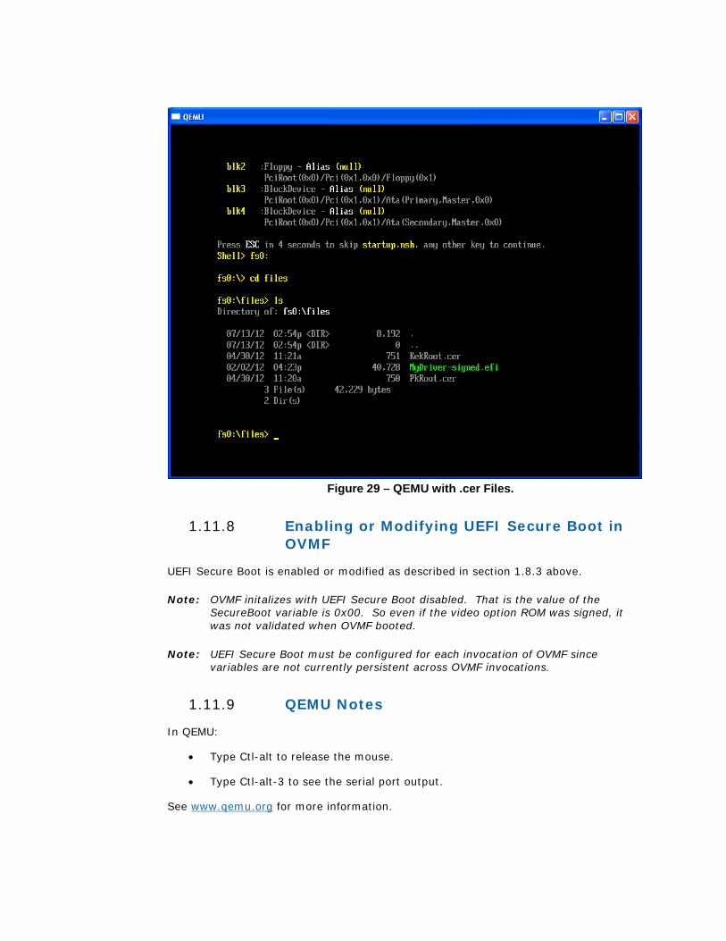
Figure 29 – QEMU with .cer Files.
1.11.8 Enabling or Modifying UEFI Secure Boot in OVMF
UEFI Secure Boot is enabled or modified as described in section 1.8.3 above.
Note: OVMF initalizes with UEFI Secure Boot disabled. That is the value of the SecureBoot variable is 0x00. So even if the video option ROM was signed, it was not validated when OVMF booted.
Note: UEFI Secure Boot must be configured for each invocation of OVMF since variables are not currently persistent across OVMF invocations.
1.11.9 QEMU Notes
In QEMU:
• Type Ctl-alt to release the mouse.
• Type Ctl-alt-3 to see the serial port output.
See www.qemu.org for more information.
Draft for Review
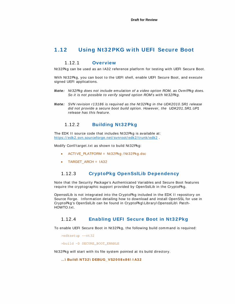
1.12 Using Nt32PKG with UEFI Secure Boot
1.12.1 Overview Nt32Pkg can be used as an IA32 reference platform for testing with UEFI Secure Boot. With Nt32Pkg, you can boot to the UEFI shell, enable UEFI Secure Boot, and execute signed UEFI applications.
Note: Nt32Pkg does not include emulation of a video option ROM, as OvmfPkg does. So it is not possible to verify signed option ROM’s with Nt32Pkg.
Note: SVN revision r13186 is required as the Nt32Pkg in the UDK2010.SR1 release did not provide a secure boot build option. However, the UDK201.SR1.UP1 release has this feature.
1.12.2 Building Nt32Pkg
The EDK II source code that includes Nt32Pkg is available at: https://edk2.svn.sourceforge.net/svnroot/edk2/trunk/edk2 .
Modify Conf/target.txt as shown to build Nt32Pkg:
• ACTIVE_PLATFORM = Nt32Pkg /Nt32Pkg.dsc
• TARGET_ARCH = IA32
1.12.3 CryptoPkg OpenSslLib Dependency
Note that the Security Package’s Authenticated Variables and Secure Boot features require the cryptographic support provided by OpenSslLib in the CryptoPkg.
OpensslLib is not integrated into the CryptoPkg included in the EDK II repository on Source Forge. Information detailing how to download and install OpenSSL for use in CryptoPkg’s OpenSslLib can be found in CryptoPkg\Library\OpensslLib\ Patch-HOWTO.txt.
1.12.4 Enabling UEFI Secure Boot in Nt32Pkg
To enable UEFI Secure Boot in Nt32Pkg, the following build command is required:
>edksetup -–nt32
>build –D SECURE_BOOT_ENABLE
Nt32Pkg will start with its file system pointed at its build directory.
…\Build\NT32\DEBUG_VS2008x86\IA32
5. Create a subdirectory here to contain images, certificates or keys that need to be enrolled in PK, KEK, DB or DBX as described in section 1.8.3 above. Oherwise these files will not be accessible from within the NT32 emulation. These are the TestRoot.cer, TestSub.cer and MyDriver.efi from section 1.4.1.5 and 1.4.1.6 above
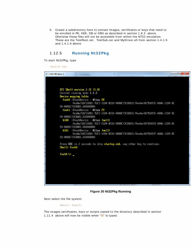
1.12.5 Running Nt32Pkg
To start Nt32Pkg, type
>build run
Figure 30 Nt32Pkg Running
Next select the file system:
Shell> fsnt0:
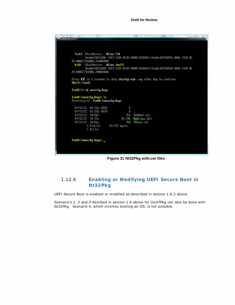
The images certificates, keys or scripts copied to the directory described in section 1.11.4 above will now be visible when “ls” is typed.
Draft for Review
Figure 31 Nt32Pkg with.cer files
1.12.6 Enabling or Modifying UEFI Secure Boot in Nt32Pkg
UEFI Secure Boot is enabled or modified as described in section 1.8.3 above.
Scenario’s 1, 2 and 3 decribed in section 1.9 above for OvmfPkg can also be done with Nt32Pkg. Scenario 4, which involves booting an OS, is not possible.