Signal Processing: Image Communication - CUHK …knngan/2013/SP-IC_v28_n7_p75… · ·...
10
An efficient framework for image/video inpainting Miaohui Wang a,n , Bo Yan b , King Ngi Ngan a a Department of Electronic Engineering, The Chinese University of Hong Kong, Shatin, Hong Kong b School of Computer Science, Fudan University, Shanghai, China article info Article history: Received 11 September 2012 Received in revised form 29 January 2013 Accepted 11 March 2013 Available online 8 April 2013 Keywords: Image inpainting Image interpolation Image restoration PDE Diffusion function abstract Image inpainting has been widely applied to many applications, such as restoring corrupted old photos, erasing video logos, concealing errors in a digital video processing system, and so on. However, traditional geometric inpainting methods suffer low efficiency. To tackle this problem, this paper addresses an efficient transform based framework for geometric methods. Given an image, we firstly decompose it, then separately perform restoration process and finally employ Laplacian diffusion function to hold local texture coherence. Experimental results show that the proposed method not only speeds up and enhances the performances of geometric methods, but also obtains a better restoration results compared with the traditional texture and hybrid methods. & 2013 Elsevier B.V. All rights reserved. 1. Introduction Digital image inpainting, also called image interpolation [1–3], image completion [4–6] or image restoration [7,8], aims at removing corrupted areas but avoiding being noticed obviously by observers, which is proposed by Bertalmio et al. [9–11]. Image inpainting is commonly used to remove video logos [12,13], restore occlusion in video sequences [14–16], edit digital photos [17–19] and compress images [20–22]. In the past decade, many inpainting methods have been widely developed by math- ematicians or computer scientists. Generally speaking, inpainting methods fall into two categories: geometric methods (non-texture) and texture based methods. Geometric methods restore the damaged image by diffusing boundary information to the missing area along the isophote lines (level lines). In [23,24], Masnou et al. restored the occlusion area along level lines. Chan et al. [25–27] developed a total variational (TV) model to restore the missing parts and later proposed a curvature driven diffusion scheme [28] by considering Euler' s Elastica. By contrast, some methods [9, 29–31] directly employed partial differential equations (PDE) to restore natural image geo- metric structures. For instance, Bertalmio et al. [9] adopted Laplace formula, and [29] adopted Navier–Stokes formula. Geometric methods restore the damaged areas from the boundary to center which indicate that only boundary pixels can be used. The constraints of geometric methods are: (1) smooth restoration results, (2) poor performance at the thick area, and (3) extensive computational time. Texture based methods begin with exploring the self- coherence features and then copy the best texture patch from restoration dictionary to the missing area. Criminisi et al. [32] proposed exemplar based method to restore the missing parts by the best patch. Exemplar based methods employed texture synthesis [33] to integrate the patch with the boundaries. In order to obtain the best patch, sparse representation methods [34–38] were proposed to utilize linear combination of blocks from an image dictionary to produce the patch. Under the assumption of containing repetitive textures, exemplar based methods may create abnormal structures that are hard to under- stand, because one order greedy approach is used in Contents lists available at SciVerse ScienceDirect journal homepage: www.elsevier.com/locate/image Signal Processing: Image Communication 0923-5965/$ - see front matter & 2013 Elsevier B.V. All rights reserved. http://dx.doi.org/10.1016/j.image.2013.03.002 n Corresponding author. Tel.: +852 5495 7535. E-mail addresses: [email protected] (M. Wang), [email protected] (B. Yan), [email protected] (K. Ngi Ngan). Signal Processing: Image Communication 28 (2013) 753–762
-
Upload
truongtuong -
Category
Documents
-
view
214 -
download
0
Transcript of Signal Processing: Image Communication - CUHK …knngan/2013/SP-IC_v28_n7_p75… · ·...

Contents lists available at SciVerse ScienceDirect
Signal Processing: Image Communication
Signal Processing: Image Communication 28 (2013) 753–762
0923-59http://d
n CorrE-m
byan@fu
journal homepage: www.elsevier.com/locate/image
An efficient framework for image/video inpainting
Miaohui Wang a,n, Bo Yan b, King Ngi Ngan a
a Department of Electronic Engineering, The Chinese University of Hong Kong, Shatin, Hong Kongb School of Computer Science, Fudan University, Shanghai, China
a r t i c l e i n f o
Article history:Received 11 September 2012Received in revised form29 January 2013Accepted 11 March 2013Available online 8 April 2013
Keywords:Image inpaintingImage interpolationImage restorationPDEDiffusion function
65/$ - see front matter & 2013 Elsevier B.V.x.doi.org/10.1016/j.image.2013.03.002
esponding author. Tel.: +852 5495 7535.ail addresses: [email protected] (M. Wdan.edu.cn (B. Yan), [email protected]
a b s t r a c t
Image inpainting has been widely applied to many applications, such as restoringcorrupted old photos, erasing video logos, concealing errors in a digital video processingsystem, and so on. However, traditional geometric inpainting methods suffer lowefficiency. To tackle this problem, this paper addresses an efficient transform basedframework for geometric methods. Given an image, we firstly decompose it, thenseparately perform restoration process and finally employ Laplacian diffusion functionto hold local texture coherence. Experimental results show that the proposed method notonly speeds up and enhances the performances of geometric methods, but also obtains abetter restoration results compared with the traditional texture and hybrid methods.
& 2013 Elsevier B.V. All rights reserved.
1. Introduction
Digital image inpainting, also called image interpolation[1–3], image completion [4–6] or image restoration [7,8],aims at removing corrupted areas but avoiding beingnoticed obviously by observers, which is proposed byBertalmio et al. [9–11]. Image inpainting is commonlyused to remove video logos [12,13], restore occlusion invideo sequences [14–16], edit digital photos [17–19] andcompress images [20–22]. In the past decade, manyinpainting methods have been widely developed by math-ematicians or computer scientists. Generally speaking,inpainting methods fall into two categories: geometricmethods (non-texture) and texture based methods.
Geometric methods restore the damaged image bydiffusing boundary information to the missing area alongthe isophote lines (level lines). In [23,24], Masnou et al.restored the occlusion area along level lines. Chan et al.[25–27] developed a total variational (TV) model to restore
All rights reserved.
ang),k (K. Ngi Ngan).
the missing parts and later proposed a curvature drivendiffusion scheme [28] by considering Euler's Elastica. Bycontrast, some methods [9,29–31] directly employed partialdifferential equations (PDE) to restore natural image geo-metric structures. For instance, Bertalmio et al. [9] adoptedLaplace formula, and [29] adopted Navier–Stokes formula.Geometric methods restore the damaged areas from theboundary to center which indicate that only boundary pixelscan be used. The constraints of geometric methods are:(1) smooth restoration results, (2) poor performance at thethick area, and (3) extensive computational time.
Texture based methods begin with exploring the self-coherence features and then copy the best texture patchfrom restoration dictionary to the missing area. Criminisiet al. [32] proposed exemplar based method to restore themissing parts by the best patch. Exemplar based methodsemployed texture synthesis [33] to integrate the patchwith the boundaries. In order to obtain the best patch,sparse representation methods [34–38] were proposedto utilize linear combination of blocks from an imagedictionary to produce the patch. Under the assumptionof containing repetitive textures, exemplar based methodsmay create abnormal structures that are hard to under-stand, because one order greedy approach is used in

M. Wang et al. / Signal Processing: Image Communication 28 (2013) 753–762754
restoration and the filling orders greatly bear the restoringresults when the missing area is thick. Based on spatial-temporal consistency, Wexler et al. [16] combined geo-metric and exemplar method to find the best patch.Bugeau [39] proposed a complex energy function tocombine PDE and exemplar based texture synthesistogether, where they stated that the hybrid energy func-tion works poor when missing area is thick or on asingular location.
Besides the above two main categories, there are someother ponderable methods. For example, in [40], Teleaet al. proposed a fast marching method to restore thedamaged image; In [41], Sun et al. proposed an interestingmethod combining user and synthesis technique togetherto restore isolated parts. In [42], Bornemann et al. pro-posed a fast hybrid variational based model. Some meth-ods [8,43] restored the given image in wavelet domain.However there are many constraints on restoration inwavelet domain: (1) boundary pixels of corrupted areabring new errors due to subtraction operations in produ-cing subbands; (2) the correlations among pixels havebeen greatly changed.
In this paper, we propose an efficient hybrid inpaintingmethod for geometric methods. To avoid constraints ofgeometric methods, the proposed transform based frame-work restores the given image in the new domain. Theproposed framework, to the best of our knowledge, isnovel and the performance is impressive. Experimentalresults show that it not only greatly speeds up traditionalgeometric methods, but also improves the PSNR by up to5.10 dB. It should be noted that the proposed frameworkis not limited to the geometric methods but can also beapplied to the texture and hybrid methods. Experimentalresults show that the proposed framework is able to
Fig. 1. Error analysis for image inpainting. (c) represents the restoration result T(T domain for comparison. (d) shows the restoration result of TðM0Þ which is fiBoth of them consume about 24 s (the same 5000 iterations) [25]: (a) ground t
produce more reasonable results than texture and hybridmethods.
The rest of this paper is organized as follows. Thetheory foundation of the proposed framework is given inSection 2. Implementation and optimization details arediscussed in Section 3. The effectiveness of our proposedmodel is evaluated in Section 4. Concluding remarks aregiven in Section 5.
2. Theory foundation of the proposed framework
Restoration procedure can be well demonstrated bythe Bayesian model [44]. In image inpainting, we aim atrestoring the original image M by maximizing the follow-ing posterior probability formula:
PðMjM0;ΩÞ ¼ PðM0jM;ΩÞPðMjΩÞPðM0jΩÞ ; ð1Þ
where M0 and Ω are the given image and the missing dataareas, respectively.
When implementing logarithmic likelihood function onboth side of Eq. (1), the target becomes
EðMjM0;ΩÞ ¼ EðM0jM;ΩÞ þ EðMjΩÞ−EðM0jΩÞ ð2Þwhere E(x) is a minus logarithmic likelihood function.
In a communication channel, since the quality degrada-tion is independent of image content itself, it indicatesPðMjΩÞ ¼ PðMÞ. Once M0 and Ω are given, EðM0jΩÞ is aconstant and the minimization problem of Eq. (2) can berewritten as
arg min : EðMjM0;ΩÞ∝EðM0jM;ΩÞ þ EðMÞ; ð3Þwhere the specific notations of E(M) and EðM0jM;ΩÞ forPDE based methods can be calculated by solving Eq. (4).
M) which is restored firstly by the TV method and then transformed in therstly transformed in the T domain and then restored by the TV method.ruth; (b) scratched M0; (c) T(M) 32.01 dB; and (d) TðM0Þ 41.59 dB.

M. Wang et al. / Signal Processing: Image Communication 28 (2013) 753–762 755
In practice, geometric method [45] is trying to mini-mize the following equation:
arg min :
ZΩ
ffiffiffiffiffiffiffiffiffiffiffiffiffiffiffiffiffiffiffiffiM2
x þM2y
qdx dyþ 1
2s2jΩc\ΩjZΩc\Ω
ðM−M0Þ2 dx dy;
ð4Þ
where ∂Ω is the boundary of the Ω which is assumed to besmooth. Since the above formula is a classical total varia-tional model [46], a PDE is solved to find the result ofEq. (4).
Our goal is to construct a framework to change theinitial condition of EðMjM0;ΩÞ so as to improve traditionalmethods efficiently to solve the above minimization pro-blem. In order to efficiently solve Eq. (4), we restore M inthe T domain and numerous experimental results verifyour strategy. Formula (5) is the foundation of the proposedtransform based framework:
Eð ~M j ~M0; ~ΩÞ ¼ TðEðMjM0;ΩÞÞ: ð5Þ
The various resolutions of video sequences greatlymotive us, where different devices require various resolu-tions of the same video sequence for displaying, such asCIF and QCIF formats. The original M0 is decomposed intofour resembling parts as shown in Fig. 1(c). Here the Ttransform is defined by the following Eq. (6) and thedetails are illustrated in Table 1:
T : M0- ~M0 ¼~M10
~M20
~M30
~M40
24
35; ð6Þ
where ~M0 and ~Mk0 ðk¼ 1;2;3;4Þ, are the new components
in T domain.After incorporating T transform, Eq. (3) can be rewrit-
ten as
arg min : Eð ~M j ~M0; ~ΩÞ∝Eð ~M0j ~M ; ~ΩÞ þ Eð ~MÞ: ð7Þ
In the following parts, we will demonstrate the advan-tages of Eð ~M j ~M0; ~ΩÞ for restoration. In general, the pro-posed T transform maintains three merits: holding localcoherence, shrinking the thick area and increasing thelength of ∂ ~Ω. It is these three properties together thatconstitute the main theory foundations of the proposedframework.
Table 1The CST algorithm.
Chain rule based T Transform algorithm
STransformðMðiÞÞBEGIN~M1ðiþ1Þ ¼ fðx; yÞjðx; yÞ ¼ ð2x;2yÞ∈ ~M ðiÞg
~M2ðiþ1Þ ¼ fðx; yÞjðx; yÞ ¼ ð2x;2y−1Þ∈ ~M ðiÞg
~M3ðiþ1Þ ¼ fðx; yÞjðx; yÞ ¼ ð2x−1;2yÞ∈ ~M ðiÞg
~M4ðiþ1Þ ¼ fðx; yÞjðx; yÞ ¼ ð2x−1;2y−1Þ∈ ~M ðiÞg
END
2.1. Holding local coherence
Fig. 1(c) shows how T transform keeps local texturecoherence. Pixels on ∂Ω of M0 and on Tð∂ΩÞ of ~M0 havesimilar neighboring circumstance. This property guaran-tees that the restoration results in the T domain are similaras that in the given domain, which keeps the traditionalinpainting methods performing well in the T domain.
2.2. Shrinking thick area
Inscribed Circle of the Hole (ICH) is the biggest inscribedcircle in the Ω areas, and employed in [47]. Generallyspeaking, the restoration performances are determined bythe radius of the Inscribed Circle of the Hole (RICH) as shownin Fig. 2.
RICH ¼MaxfR∂Ω1 ;R∂Ω2 ;…;R∂ΩN g: ð8ÞThe RICH in ~M
i0 ði¼ 1;2;3;4Þ is a quarter of the RICH in
M0 which is crucial for inpainting methods. Bugeau et al.[39] stated that one of constraints in their method is therestoration of thick area, although they have constructed ahybrid framework for digital image inpainting. Therefore,restoration of thick area is still a challenge task for state-of-the-art inpainting methods. If RICH decreases, the accu-mulated error to center pixels also decreases. In thatsituation, texture methods produce less abnormal repeti-tive results, and geometric methods obtain more informa-tion from boundary pixels for one iteration.
Let BΩ ¼ fΘðiÞji¼ 1;2;3;…;Ng be a set containing theboundary pixels of all holes in M0, and ΘðiÞ ¼ fðx; yÞjðx; yÞ∈M∂Ωi g be the boundary pixels in the ith hole of Ω. Letξj be the correct propagation rate of the jth step along thenormal orientation of level line at pixel P0 as shown in Fig. 3,and εi ¼ fε1i ; ε2i ;…; εki ;…g be the error information of the ithhole, where εki is the error information in the kth step along
Fig. 2. The definition of the biggest inscribed circle of Ω area. There aretwo holes with different biggest inscribed circles in the picture withwidth M and height N.
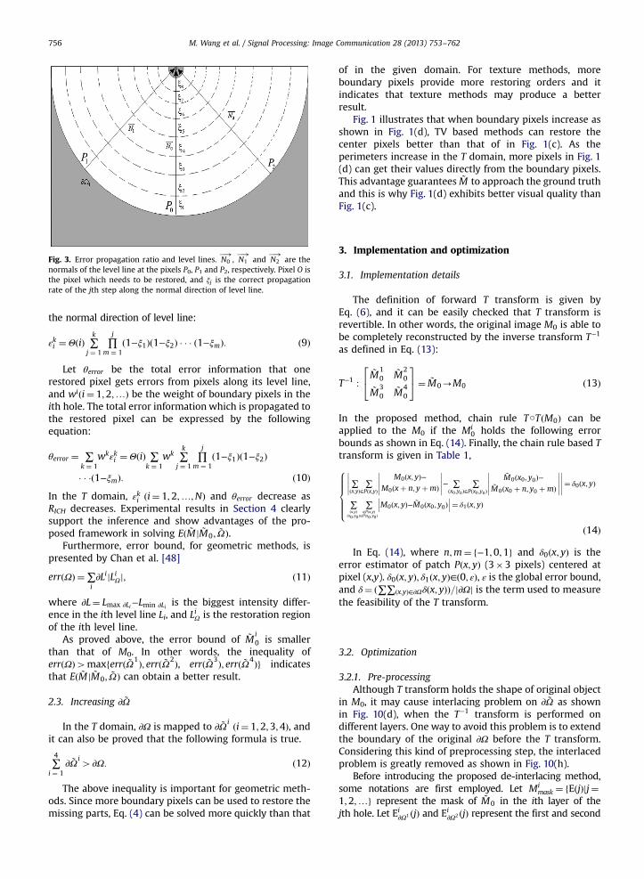
Fig. 3. Error propagation ratio and level lines. N0�!
, N1�!
and N2�!
are thenormals of the level line at the pixels P0, P1 and P2, respectively. Pixel O isthe pixel which needs to be restored, and ξj is the correct propagationrate of the jth step along the normal direction of level line.
M. Wang et al. / Signal Processing: Image Communication 28 (2013) 753–762756
the normal direction of level line:
εki ¼ΘðiÞ ∑k
j ¼ 1∏j
m ¼ 1ð1−ξ1Þð1−ξ2Þ � � � ð1−ξmÞ: ð9Þ
Let θerror be the total error information that onerestored pixel gets errors from pixels along its level line,and wiði¼ 1;2;…Þ be the weight of boundary pixels in theith hole. The total error information which is propagated tothe restored pixel can be expressed by the followingequation:
θerror ¼ ∑k ¼ 1
wkεki ¼ΘðiÞ ∑k ¼ 1
wk ∑k
j ¼ 1∏j
m ¼ 1ð1−ξ1Þð1−ξ2Þ
� � �ð1−ξmÞ: ð10ÞIn the T domain, εki ði¼ 1;2;…;NÞ and θerror decrease asRICH decreases. Experimental results in Section 4 clearlysupport the inference and show advantages of the pro-posed framework in solving Eð ~M j ~M0; ~ΩÞ.
Furthermore, error bound, for geometric methods, ispresented by Chan et al. [48]
errðΩÞ ¼∑i∂LijLiΩj; ð11Þ
where ∂L¼ Lmax ∂Li−Lmin ∂Li is the biggest intensity differ-ence in the ith level line Li, and LiΩ is the restoration regionof the ith level line.
As proved above, the error bound of ~Mi0 is smaller
than that of M0. In other words, the inequality oferrðΩÞ4maxferrð ~Ω1Þ; errð ~Ω2Þ, errð ~Ω3Þ; errð ~Ω4Þg indicatesthat Eð ~M j ~M0; ~ΩÞ can obtain a better result.
2.3. Increasing ∂ ~Ω
In the T domain, ∂Ω is mapped to ∂ ~Ω i ði¼ 1;2;3;4Þ, andit can also be proved that the following formula is true.
∑4
i ¼ 1∂ ~Ω i
4∂Ω: ð12Þ
The above inequality is important for geometric meth-ods. Since more boundary pixels can be used to restore themissing parts, Eq. (4) can be solved more quickly than that
of in the given domain. For texture methods, moreboundary pixels provide more restoring orders and itindicates that texture methods may produce a betterresult.
Fig. 1 illustrates that when boundary pixels increase asshown in Fig. 1(d), TV based methods can restore thecenter pixels better than that of in Fig. 1(c). As theperimeters increase in the T domain, more pixels in Fig. 1(d) can get their values directly from the boundary pixels.This advantage guarantees ~M to approach the ground truthand this is why Fig. 1(d) exhibits better visual quality thanFig. 1(c).
3. Implementation and optimization
3.1. Implementation details
The definition of forward T transform is given byEq. (6), and it can be easily checked that T transform isrevertible. In other words, the original image M0 is able tobe completely reconstructed by the inverse transform T−1
as defined in Eq. (13):
T−1 :~M10
~M20
~M30
~M40
24
35¼ ~M0-M0 ð13Þ
In the proposed method, chain rule T○TðM0Þ can beapplied to the M0 if the Mi
0 holds the following errorbounds as shown in Eq. (14). Finally, the chain rule based Ttransform is given in Table 1,
∑ðx;yÞ
∑∈Pðx;yÞ
M0ðx; yÞ−M0ðxþ n; yþmÞ
����������− ∑
ðx0 ;y0Þ∑
∈Pðx0 ;y0Þ
~M0ðx0; y0Þ−~M0ðx0 þ n; y0 þmÞ
����������
����������¼ δ0ðx; yÞ
∑ðx;yÞ
ðx0 ;y0 Þ
∑∈Pðx;yÞ
∈Pðx0 ;y0 Þ
M0ðx; yÞ− ~M0ðx0; y0Þ��� ���¼ δ1ðx; yÞ
8>>>>><>>>>>:
ð14Þ
In Eq. (14), where n;m¼ f−1;0;1g and δ0ðx; yÞ is theerror estimator of patch Pðx; yÞ (3�3 pixels) centered atpixel (x,y). δ0ðx; yÞ; δ1ðx; yÞ∈ð0; εÞ, ε is the global error bound,and δ¼ ð∑∑ðx;yÞ∈∂Ωδðx; yÞÞ=j∂Ωj is the term used to measurethe feasibility of the T transform.
3.2. Optimization
3.2.1. Pre-processingAlthough T transform holds the shape of original object
in M0, it may cause interlacing problem on ∂ ~Ω as shownin Fig. 10(d), when the T−1 transform is performed ondifferent layers. One way to avoid this problem is to extendthe boundary of the original ∂Ω before the T transform.Considering this kind of preprocessing step, the interlacedproblem is greatly removed as shown in Fig. 10(h).
Before introducing the proposed de-interlacing method,some notations are first employed. Let Mi
mask ¼ fEðjÞjj¼1;2;…g represent the mask of ~M0 in the ith layer of thejth hole. Let Ei∂Ω1 ðjÞ and Ei
∂Ω2 ðjÞ represent the first and second

Table 2The workflow of the proposed framework.
DTF based algorithm
Step 1. BEGIN
Step 2. set initial value: i¼0;
Step 3. construct a pre-processing picture Mpi ¼Mi and calculate δ, ε;
Step 4. Mipðx; yÞ ¼Mi
pðx71; y71Þ, if Mipðx; yÞ∈Ei
∂Ω1 ðjÞ and Mipðx71; y71Þ∈Ei
∂Ω2 ðjÞ belong to different objects, Formula (15);
Step 5.
if δoε
STtransformðMiÞ; i¼ iþ 1; Stepð3Þif δ4 ¼ ε
maxChain¼ i; Stepð6Þ
8>>>>>><>>>>>>:
;
Step 6: restore the damaged picture Mipðx; yÞ ¼
if i¼ ¼maxChain
Candidate Inpainting AlgorithmsðxÞif iomaxChainFormula ð17Þ Iteration¼ 10
8>>>><>>>>:
;
Step 7. Miðx; yÞ ¼Mi
pðx; yÞ Mimask ¼ 1
Miðx; yÞ Mimask ¼ 0
8<: ;
Step 8. reconstruct the picture Mi−1p ðx; yÞ;
Step 9. update the argument i¼ i−1 and perform:if i4 ¼ 1Return to Stepð7Þ:if i¼ ¼ 0Perform Stepð7Þ: End�of�DTF :
8>>>><>>>>:
;
Step 10:END
M. Wang et al. / Signal Processing: Image Communication 28 (2013) 753–762 757
undamaged boundary pixels in the jth hole, respectively,
Ei∂Ω1 ðjÞ ¼ fðxþ ℏ; yþ ℓÞjℏ;ℓ¼ 0; 71and ðx; yÞ∈θðjÞ
Ei∂Ω2 ðjÞ ¼ fðxþ ℏ; yþ ℓÞjℏ;ℓ¼ 0; 72 and ðx; yÞ∈θðjÞ:
8><>: ð15Þ
If Mi∂Ω1 ðx; yÞ and Mi
∂Ω2 ðm;nÞ are neighboring pixels,Mi
∂Ω2 ðm;nÞ is reset as Mi∂Ω1 ðx; yÞ when this pair of pixels
satisfy the following conditions:
Mi∂Ω1 ðx7ℏ; y7ℓÞ≠Mi
∂Ω1 ðm;nÞMi
∂Ω1 ðx7ℏ; y7ℓÞ∉θðjÞMi
∂Ω1 ðx; yÞ∈Ei∂Ω1 ðjÞ;Mi∂Ω2 ðm;nÞ∈Ei∂Ω2 ðjÞ
ðm;nÞ ¼ ðxþ ℏ; yþ ℓÞ;ℏ;ℓ¼ 0; 71:
8>>>>><>>>>>:
ð16Þ
3.2.2. Post-processingTo guarantee the coherence of boundary pixels at each
layer of the T−1 transform, Laplacian formula is used torevise the inconsistencies among pixels at each layerduring the reverse process as show in Fig. 10(d) and (h):
∂2Mi0
∂x2þ ∂2Mi
0
∂y2¼ 0: ð17Þ
Laplacian diffusion function Eq. (17) is employed tomaintain neighboring pixels coherence and parameters ischose to avoid resulting in smooth problem. Details, likecontrolling iterations, have been given in Table 2. In theend of this subsection, the details of the proposed diffu-sion based T transform framework (DTF) is shown inTable 2.
4. Simulation results
In this section, the effectiveness of the DTF method isevaluated by extensive experimental results, and theobjective performance is measured by peak signal to noiseratio (PSNR). The proposed DTF method and other inpaint-ing methods [9,16,25,32,40,42] are tested on a dual-corePC(RAM 3072 M and CPU 2.53 GHz). For simplicity, theitem maxChain is manually set to two except for Fig. 4 dueto the low image resolutions. The restoration process ofDTF takes four steps as shown in Table 2: (1) forward Ttransform; (2) performing traditional restoration; (3)inverse T transform, and (4) diffusion process. Candidates(x) can be geometric [9,25,40], texture [32], or hybridmethods [16,42].

Fig. 4. Results of Bertalmio et al. [9] and DTF based method for Tarja. 4(a) represents the results of Bertalmio et al. [9] with iterations¼100, 1000, 1500,3000 from left to right. The restoration result of DTF method with 30 iterations is shown in (b) (maxChain¼3). (c) illustrates the comparison result ofBertalmio and DTF model: left is the result of Bertalmio et al. [9] with iteration¼3000 (3279 s). Right is the DTF method with iteration¼30 (33 s). Note thatthere still exist clearly scratches on the Tarja's hand: (a) Bertalmio et al. [9], Iteration¼100, PSNR¼21.78 dB (left), 1000, 30.18 dB, 1500, 32.06 dB, 3000,35.72 dB (right); (b) DTF Iteration¼30, 37.84 dB and (c) Tarja mirror-effect.
Fig. 5. Results of geometric inpainting methods and DTF method for Foreman video. (b)–(d) show the results of geometric methods [9,25,40], respectively.The DTF based results are shown correspondingly for comparison: (a) original; (b) [9] 41.10 dB; (c) [25] 41.56 dB; (d) [40] 40.86 dB; (e) scratch; (f) DTF41.47 dB; (g) DTF 42.36 dB; and (h) DTF 41.59 dB.
M. Wang et al. / Signal Processing: Image Communication 28 (2013) 753–762758
4.1. DTF for geometric methods
In Fig. 4, it is observed that DTF method remarkablyenhances the speed of the classical inpainting method [9],
and it also indicates that DTF method works efficientlyunder the thick area as shown in Fig. 10(b). Under thesame parameters, our DTF method outperforms Bertalmioet al. [9]. It should be noted that, as shown in Fig. 10(c), the

Fig. 6. Results of geometric inpainting methods and DTF method for Peony: (a) original; (b) [9] 30.17 dB; (c) [25] 31.14 dB; (d) [40] 31.20 dB; (e) scratch;(f) DTF 30.85 dB; (g) DTF 31.14 dB; and (h) DTF 31.22 dB.
Table 3Performances of proposed DTF framework for geometric methods.
Name Methods Size Time saving (s) PSNR (dB)
Ori. DTF Δ Gain (%) Ori. DTF Δ Gain
Tarja [9] 584�864 3279 33 98.99 35.72 37.84 +2.12[25] 584�864 1980 61 96.92 37.30 38.18 +0.79[40] 584�864 160 29 81.87 37.90 38.10 +0.20
Eye [9] 200�200 440 11 97.50 19.18 24.28 +5.10[25] 200�200 433 16 96.30 25.36 27.46 +2.10[40] 200�200 20 5 75.00 27.73 29.37 +1.64
Pepper [9] 512�384 631 15 97.62 31.41 33.45 +2.04[25] 512�384 810 33 95.93 33.04 33.75 +0.71[40] 512�384 52 5 90.38 33.52 33.73 +0.21
Peony [9] 768�512 1580 12 99.24 30.17 30.85 +0.68[25] 768�512 1220 25 97.95 31.14 31.14 +0.00[40] 768�512 105 5 95.24 31.20 31.22 +0.02
Foreman [9] 640�560 185 8 95.68 41.10 41.47 +0.37[25] 640�560 1170 33 97.18 41.56 42.36 +0.80[40] 640�560 120 21 82.50 40.86 41.59 +0.73
Average Δ Time saving (%) 93.20%Δ PSNR (dB) +1.17
M. Wang et al. / Signal Processing: Image Communication 28 (2013) 753–762 759
DTF method is able to save more time than method [9]and maintain the similar visual quality. For example, theproposed DTF method takes about 33 s, while Bertalmio[9] takes 3279 s nearly 100 times of the DTF method.
Fig. 5 depicts the performance of geometric methodsand DTF method to restore the Foreman video sequence. Itshows that both the DTF and geometric methods obtainthe similar visual quality. However, the DTF method savesnearly 90% of time compared with geometric methods[9,25,40].
Fig. 6 depicts the performance of geometric methodsand DTF method to restore the Peony picture. Experimen-tal results show that both the geometric and DTF basedmethod efficiently restore the yellow scratches. Obviously,it is a great advantage that our proposed method savesmore time than the traditional geometric methods[9,25,40].
In Table 3, we give the overall performance of the DTFmethod versus the geometric methods. It is observed that
our DTF method improves the PSNR 1.17 dB in average, andmeanwhile it saves time by 93.2%.
4.2. DTF for texture methods
In this subsection, we illustrate the results of the DTFmethod versus texture methods. Fig. 7 shows that theproposed framework improves texture method to restorethe missing parts. Fig. 7(b) shows that Criminisi et al. [32]produces irrational white patches on the surface of somesteps, while Fig. 7(d) shows that the DTF method restores thetexture perfectly.
Fig. 8 shows a girl running on the beach. The exemplarbased method [32] is used to remove the girl but it causesexplicit ink marks on the missing area as shown in Fig. 8(b). In Fig. 8(d), the DTF method restores the missing areawith the same texture from the background as expected.
In Fig. 9, we show the ability of the DTF method for edgereconstruction and very large object restoration. Fig. 9(b) and
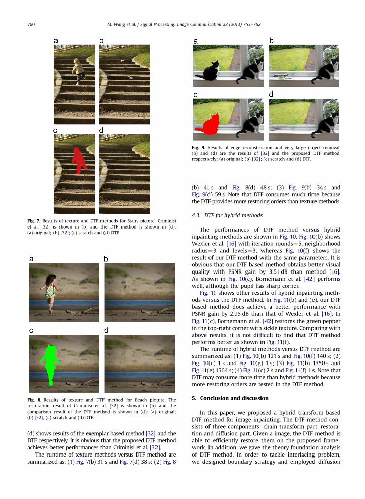
Fig. 7. Results of texture and DTF methods for Stairs picture. Criminisiet al. [32] is shown in (b) and the DTF method is shown in (d):(a) original; (b) [32]; (c) scratch and (d) DTF.
Fig. 8. Results of texture and DTF method for Beach picture. Therestoration result of Criminisi et al. [32] is shown in (b) and thecomparison result of the DTF method is shown in (d): (a) original;(b) [32]; (c) scratch and (d) DTF.
Fig. 9. Results of edge reconstruction and very large object removal.(b) and (d) are the results of [32] and the proposed DTF method,respectively: (a) original; (b) [32]; (c) scratch and (d) DTF.
M. Wang et al. / Signal Processing: Image Communication 28 (2013) 753–762760
(d) shows results of the exemplar based method [32] and theDTF, respectively. It is obvious that the proposed DTF methodachieves better performances than Criminisi et al. [32].
The runtime of texture methods versus DTF method aresummarized as: (1) Fig. 7(b) 31 s and Fig. 7(d) 38 s; (2) Fig. 8
(b) 41 s and Fig. 8(d) 48 s; (3) Fig. 9(b) 34 s andFig. 9(d) 59 s. Note that DTF consumes much time becausethe DTF provides more restoring orders than texture methods.
4.3. DTF for hybrid methods
The performances of DTF method versus hybridinpainting methods are shown in Fig. 10. Fig. 10(b) showsWexler et al. [16] with iteration rounds¼5, neighborhoodradius¼3 and levels¼3, whereas Fig. 10(f) shows theresult of our DTF method with the same parameters. It isobvious that our DTF based method obtains better visualquality with PSNR gain by 3.51 dB than method [16].As shown in Fig. 10(c), Bornemann et al. [42] performswell, although the pupil has sharp corner.
Fig. 11 shows other results of hybrid inpainting meth-ods versus the DTF method. In Fig. 11(b) and (e), our DTFbased method does achieve a better performance withPSNR gain by 2.95 dB than that of Wexler et al. [16]. InFig. 11(c), Bornemann et al. [42] restores the green pepperin the top-right corner with sickle texture. Comparing withabove results, it is not difficult to find that DTF methodperforms better as shown in Fig. 11(f).
The runtime of hybrid methods versus DTF method aresummarized as: (1) Fig. 10(b) 121 s and Fig. 10(f) 140 s; (2)Fig. 10(c) 1 s and Fig. 10(g) 1 s; (3) Fig. 11(b) 1350 s andFig. 11(e) 1564 s; (4) Fig. 11(c) 2 s and Fig. 11(f) 1 s. Note thatDTF may consume more time than hybrid methods becausemore restoring orders are tested in the DTF method.
5. Conclusion and discussion
In this paper, we proposed a hybrid transform basedDTF method for image inpainting. The DTF method con-sists of three components: chain transform part, restora-tion and diffusion part. Given a image, the DTF method isable to efficiently restore them on the proposed frame-work. In addition, we gave the theory foundation analysisof DTF method. In order to tackle interlacing problem,we designed boundary strategy and employed diffusion
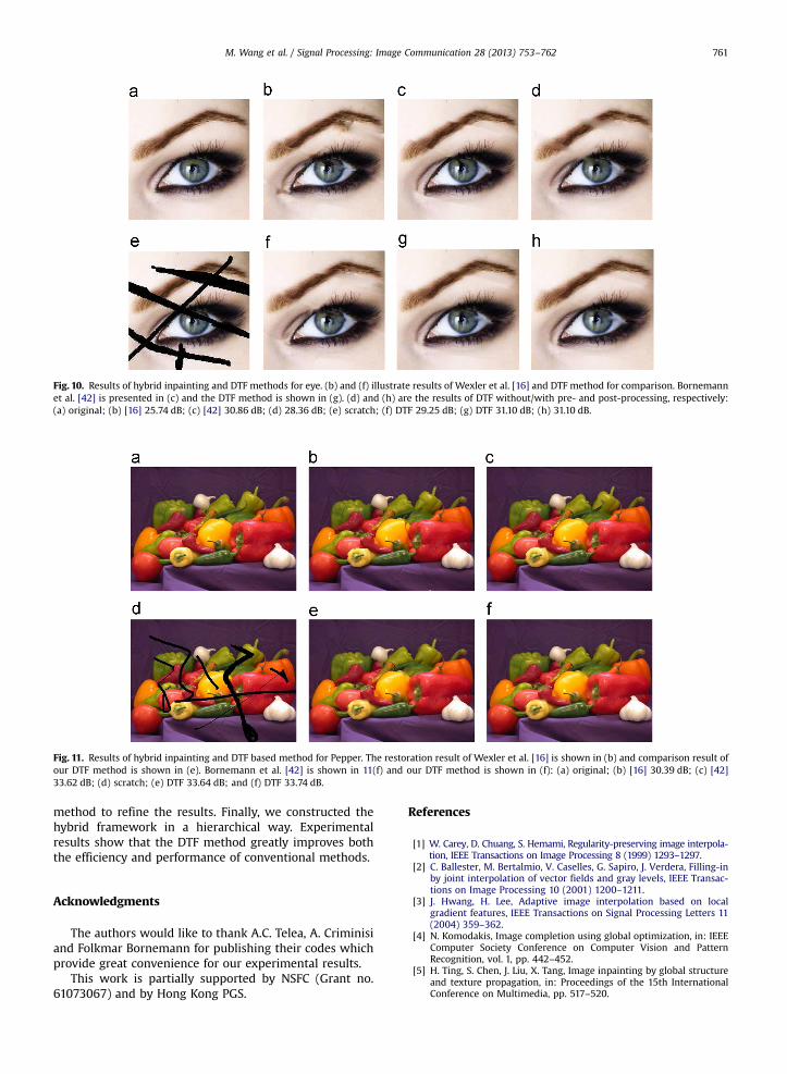
Fig. 10. Results of hybrid inpainting and DTF methods for eye. (b) and (f) illustrate results of Wexler et al. [16] and DTF method for comparison. Bornemannet al. [42] is presented in (c) and the DTF method is shown in (g). (d) and (h) are the results of DTF without/with pre- and post-processing, respectively:(a) original; (b) [16] 25.74 dB; (c) [42] 30.86 dB; (d) 28.36 dB; (e) scratch; (f) DTF 29.25 dB; (g) DTF 31.10 dB; (h) 31.10 dB.
Fig. 11. Results of hybrid inpainting and DTF based method for Pepper. The restoration result of Wexler et al. [16] is shown in (b) and comparison result ofour DTF method is shown in (e). Bornemann et al. [42] is shown in 11(f) and our DTF method is shown in (f): (a) original; (b) [16] 30.39 dB; (c) [42]33.62 dB; (d) scratch; (e) DTF 33.64 dB; and (f) DTF 33.74 dB.
M. Wang et al. / Signal Processing: Image Communication 28 (2013) 753–762 761
method to refine the results. Finally, we constructed thehybrid framework in a hierarchical way. Experimentalresults show that the DTF method greatly improves boththe efficiency and performance of conventional methods.
Acknowledgments
The authors would like to thank A.C. Telea, A. Criminisiand Folkmar Bornemann for publishing their codes whichprovide great convenience for our experimental results.
This work is partially supported by NSFC (Grant no.61073067) and by Hong Kong PGS.
References
[1] W. Carey, D. Chuang, S. Hemami, Regularity-preserving image interpola-tion, IEEE Transactions on Image Processing 8 (1999) 1293–1297.
[2] C. Ballester, M. Bertalmio, V. Caselles, G. Sapiro, J. Verdera, Filling-inby joint interpolation of vector fields and gray levels, IEEE Transac-tions on Image Processing 10 (2001) 1200–1211.
[3] J. Hwang, H. Lee, Adaptive image interpolation based on localgradient features, IEEE Transactions on Signal Processing Letters 11(2004) 359–362.
[4] N. Komodakis, Image completion using global optimization, in: IEEEComputer Society Conference on Computer Vision and PatternRecognition, vol. 1, pp. 442–452.
[5] H. Ting, S. Chen, J. Liu, X. Tang, Image inpainting by global structureand texture propagation, in: Proceedings of the 15th InternationalConference on Multimedia, pp. 517–520.

M. Wang et al. / Signal Processing: Image Communication 28 (2013) 753–762762
[6] N. Komodakis, G. Tziritas, Image completion using efficient beliefpropagation via priority scheduling and dynamic pruning, IEEETransactions on Image Processing 16 (2007) 2649–2661.
[7] J. Mairal, M. Elad, G. Sapiro, Sparse representation for color imagerestoration, IEEE Transactions on Image Processing 17 (2008) 53–69.
[8] C. Hsieh, Y. Chen, C. Hsu, Fast image restoration method based on themulti-resolution layer, Tamkang Journal of Science and Engineering12 (2009) 439–448.
[9] M. Bertalmio, G. Sapiro, V. Caselles, C. Ballester, Image inpainting,in: Proceedings of Computer Graphics and Interactive Techniques,SIGGRAPH 2000, pp. 417–424.
[10] M. Bertalmio, L. Vese, G. Sapiro, S. Osher, Simultaneous structureand texture image inpainting, IEEE Transactions on Image Processing12 (2003) 882–889.
[11] S. Rane, G. Sapiro, M. Bertalmio, Structure and texture filling-in ofmissing image blocks in wireless transmission and compressionapplications, IEEE Transactions on Image Processing 12 (2003)296–303.
[12] W. Yan, M. Kankanhalli, Erasing video logos based on imageinpainting, in: IEEE International Conference on Multimedia andExpo (ICME 2002), vol. 2, pp. 521–524.
[13] W. Yan, J. Wang, M. Kankanhalli, Automatic video logo detection andremoval, Multimedia Systems 10 (2005) 379–391.
[14] K. Patwardhan, G. Sapiro, M. Bertalmio, Video inpainting of occlud-ing and occluded objects, in: IEEE International Conference on ImageProcessing (ICIP 2005), vol. 2, pp. II–69–72.
[15] K. Patwardhan, G. Sapiro, M. Bertalmío, Video inpainting underconstrained camera motion, IEEE Transactions on Image Processing16 (2007) 545.
[16] Y. Wexler, E. Shechtman, M. Irani, Space-time completion of video,IEEE Transactions on Pattern Analysis and Machine Intelligence 29(2007) 463–476.
[17] P. Pérez, M. Gangnet, A. Blake, Patchworks: Example-Based RegionTiling for Image Editing, Technical Report MSR-TR-2004-04, Micro-soft Research, Redmond, WA, 2004.
[18] Y. Pritch, E. Kav-Venaki, S. Peleg, Shift-map image editing, in: IEEE12th International Conference on Computer Vision, pp. 151–158.
[19] C. Barnes, E. Shechtman, A. Finkelstein, D. Goldman, Patchmatch: arandomized correspondence algorithm for structural image editing,in: ACM Transactions on Graphics (TOG), vol. 28, p. 24.
[20] C. Wang, X. Sun, F. Wu, H. Xiong, Image compression with structure-aware inpainting, in: 2006 IEEE International Symposium onCircuits and Systems (ISCAS 2006), IEEE, p. 4.
[21] D. Liu, X. Sun, F. Wu, S. Li, Y. Zhang, Image compression with edge-based inpainting, IEEE Transactions on Circuits and Systems forVideo Technology 17 (2007) 1273–1287.
[22] Z. Xiong, X. Sun, F. Wu, Block-based image compression withparameter-assistant inpainting, IEEE Transactions on Image Proces-sing 19 (2010) 1651–1657.
[23] S. Masnou, J. Morel, Level lines based disocclusion, in: IEEE Inter-national Conference on Image Processing (ICIP 2005), pp. 259–263.
[24] S. Masnou, Disocclusion: a variational approach using level lines,IEEE Transactions on Image Processing 11 (2002) 68–76.
[25] T. Chan, J. Shen, Mathematical models for local nontexture inpaint-ings, SIAM Journal on Applied Mathematics 62 (2001) 1019–1043.
[26] T. Chan, J. Shen, L. Vese, Variational PDE models in image processing,Notices of the American Mathematical Society 50 (2003) 14–26.
[27] T. Chan, J. Shen, Image Processing and Analysis: Variational, PDE,Wavelet, and Stochastic Methods, Society for Industrial Mathe-matics, 2005.
[28] T. Chan, J. Shen, Nontexture inpainting by curvature-driven diffu-sions, Journal of Visual Communication and Image Representation12 (2001) 436–449.
[29] M. Bertalmio, A. Bertozzi, G. Sapiro, et al., Navier–Stokes, fluiddynamics, and image and video inpainting, in: IEEE ComputerSociety Conference on Computer Vision and Pattern Recognition(CVPR 2001), vol. 1.
[30] M. Bertalmio, Strong-continuation, contrast-invariant inpaintingwith a third-order optimal PDE, IEEE Transactions on Image Proces-sing 15 (2006) 1934–1938.
[31] A. Bertozzi, S. Esedoglu, A. Gillette, Inpainting of binary images usingthe Cahn–Hilliard equation, IEEE Transactions on Image Processing16 (2007) 285–291.
[32] A. Criminisi, P. Pérez, K. Toyama, Region filling and object removal byexemplar-based image inpainting, IEEE Transactions on ImageProcessing 13 (2004) 1200–1212.
[33] A. Efros, T. Leung, Texture synthesis by non-parametric sampling, in:Proceedings of the 7th IEEE International Conference on ComputerVision (ICCV 1999), vol. 2, pp. 1033–1038.
[34] M. Fadili, J. Starck, Em algorithm for sparse representation-basedimage inpainting, in: IEEE International Conference on ImageProcessing, vol. 2, pp. II–61.
[35] M. Elad, M. Aharon, Image denoising via sparse and redundantrepresentations over learned dictionaries, IEEE Transactions onImage Processing 15 (2006) 3736–3745.
[36] O.G. Guleryuz, Nonlinear approximation based image recovery usingadaptive sparse reconstructions and iterated denoising. Part II.:Adaptive algorithms, IEEE Transactions on Image Processing 15(2006) 555–571.
[37] X. Li, Image recovery via hybrid sparse representations: a determi-nistic annealing approach, IEEE Journal of Selected Topics in SignalProcessing 5 (2011) 953–962.
[38] Z. Xu, J. Sun, Image inpainting by patch propagation using patchsparsity, IEEE Transactions on Image Processing 19 (2010)1153–1165.
[39] A. Bugeau, M. Bertalmío, V. Caselles, G. Sapiro, A comprehensiveframework for image inpainting, IEEE Transactions on ImageProcessing 19 (2010) 2634–2645.
[40] A. Telea, An image inpainting technique based on the fast marchingmethod, Journal of Graphics Tools 9 (2004) 23–34.
[41] J. Sun, L. Yuan, J. Jia, H. yeung Shum, Image completion withstructure propagation, ACM Transactions on Graphics 24 (2005)861–868.
[42] F. Bornemann, T. März, Fast image inpainting based on coherencetransport, Journal of Mathematical Imaging and Vision 28 (2007)259–278.
[43] D. Cho, T. Bui, Image inpainting using wavelet-based inter-and intra-scale dependency, in: 19th International Conference on PatternRecognition (ICPR 2008), pp. 1–4.
[44] J. Shen, Inpainting and the fundamental problem of image proces-sing, SIAM News 36 (2003) 1–4.
[45] T. Chan, J. Shen, Variational image inpainting, Communications onPure and Applied Mathematics 58 (2005) 579–619.
[46] L. Rudin, S. Osher, E. Fatemi, Nonlinear total variation based noiseremoval algorithms, Physica D 60 (1992) 259–268.
[47] M. Wang, B. Yan, H. Gharavi, Pyramid model based down-samplingfor image inpainting, in: IEEE International Conference on ImageProcessing (ICIP 2010), pp. 429–432.
[48] T. Chan, S. Kang, Error analysis for image inpainting, Journal ofMathematical Imaging and Vision 26 (2006) 85–103.