Signal Microwave · Signal Microwave Narrow Profile ELF110-001 Standard Profile ELF110-002 Common...
4
Connector Products Nov. 2017
Transcript of Signal Microwave · Signal Microwave Narrow Profile ELF110-001 Standard Profile ELF110-002 Common...

Part No. 907-xxx-10077
Signal Microwave, LLCChandler, Arizona [email protected] (480) 322-4992
Test Boards for Edge Launch Connectors (40 GHz and 70 GHz)
Broadband Test Verification Boards (40 GHz and 70 GHz)
Adapters 1.85 mm (70 GHz)
Signal Microwave
• All test board launch designs are available at no charge in .pdf and .dxf formats
• 1” and 2” length microstrip and grounded coplanar waveguide (GCPWG) boards available
• Available in both 40 GHz and 70 GHz versions
Connector Products Nov. 2017
Part No. 907-xxx-10074
Vias thru 8 mil RO 4003
Vias not thru FR-4 backer
80 mil FR-4
8 mil RO 4003
Typical test Data is shown in the Edge Launch Connector section. Demo boards are also available with sample connectors and test data.
Part No. 907-xxx-10072
Part No. 907-xxx-10075
“xxx” is a placeholder to define frequency range depending on connector types.
40 GHz Test Board Part Numbers:
007-007-1Fn 1” Microstrip
007-007-2Fn 2” Microstrip
008-008-1Fn 1” Grounded Coplanar Waveguide (GCPWG)
008-008-2Fn 2” Grounded Coplanar Waveguide (GCPWG)
70 GHz Test Board Part Numbers:
020-020-1Fn 1” Microstrip
020-020-2Fn 2” Microstrip
021-021-1Fn 1” Grounded Coplanar Waveguide (GCPWG)
021-021-2Fn 2” Grounded Coplanar Waveguide (GCPWG)
AF70F70-001 AF70M70-001 AM70M70-001
• 1.85 mm Interfaces
• Versions available with push-on 1.85 mm interfaces
• 70 GHz Bandwidth
• Standard 5/16” Wrench Flat on Housing
• Gold Plated Housing
• Custom Housing Configurations Available
All Text and Images are Copyright © 2012–2017 Signal Microwave, LLC
Signal Microwave
Narrow ProfileELF110-001
Standard ProfileELF110-002
Common InterfaceELF110
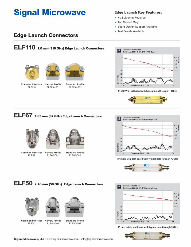
ELF110 1.0 mm (110 GHz) Edge Launch Connectors
ELF67 1.85 mm (67 GHz) Edge Launch Connectors
Narrow ProfileELF67-001
Standard ProfileELF67-002
Common InterfaceELF67
ELF50 2.40 mm (50 GHz) Edge Launch Connectors
Edge Launch Key Features:
• No Soldering Required
• Top Ground Only
• Board Design Support Available
• Test Boards AvailableELF40 2.92 mm (40 GHz) Edge Launch Connectors
Vertical Launch Connectors VLF40 2.92 mm (40 GHz)
• 40 GHz Bandwidth
• 2.92 mm Connector for high speed digital industry with superior electrical performance
• Compression fit, screw-on mounting, does not require soldering
Narrow ProfileELF50-001
Standard ProfileELF50-002
Common InterfaceELF50
Narrow ProfileELF40-001
Standard ProfileELF40-002
Common InterfaceELF40
VLF40-002
Signal Microwave
• 2.92 mm Interface
• Standard 2 & 4 Hole Flanges
• 40 GHz Bandwidth
• Rear Socket for 12 mil pin
• Low VSWR: DC – 27.0 GHz......1.10:1 27.0 – 40.0 GHz....1.15:1
• Temp Range -55º to +105º
• DFARS Compliant
Signal Microwave, LLC • www.signalmicrowave.com • [email protected] Signal Microwave, LLC • www.signalmicrowave.com • [email protected]
Edge Launch Connectors
Field Replaceable Connectors
FRF40 2.92 mm (40 GHz)
FRF40-001
Connector: ELF110-001Test Board: 045-045-2Fn 2” GCPWG Board
2” GCPWG test board with typical data through 110 GHz
Connector: ELF67-002Test Board: 020-020-2Fn 2” Microstrip Board
2” microstrip test board with typical data through 70 GHz
Connector: ELF50-002Test Board: 020-020-2Fn 2” Microstrip Board
2” microstrip test board with typical data through 50 GHz
Connector: ELF40-002Test Board: 007-007-2Fn 1” Microstrip Board
-12.0
-9.0
-6.0
-3.0
0.0
1.0
1.2
1.4
1.6
1.8
0 20 40Frequency (GHz)
S11
(VSW
R)
S21
(dB
)
1” microstrip test board with typical data through 40 GHz
Connector: FRF40-001Tested as back-to-back pair
-0.8
-0.6
-0.4
-0.2
0.0
1.0
1.1
1.2
1.3
1.4
0 20 40Frequency (GHz)
S11
(VSW
R)
S21
(dB
)
Typical test data through 40 GHz using FRF40-001 back-to-back connector pair with test pin.
Connector: VLF40-002Tested as back-to-back pair
-0.8
-0.6
-0.4
-0.2
0.0
1.0
1.2
1.4
1.6
1.8
0 20 40Frequency (GHz)
S11
(VSW
R)
S21
(dB
)
Typical data for 2 connectors tested as a back-to-back pair
.625” .550”
.500” .500”
FRF40-001 FRF40-002
FRF40-003 FRF40-004
FRF40-005
.375”
-12.0
-9.0
-6.0
-3.0
0.0
1.0
1.2
1.4
1.6
1.8
0 25 50Frequency (GHz)
S11
(VSW
R)
S21
(dB
)
-12.0
-9.0
-6.0
-3.0
0.0
1.0
1.2
1.4
1.6
1.8
0 35 70Frequency (GHz)
S11
(VSW
R)
S21
(dB
)
-12.0
-9.0
-6.0
-3.0
0.0
1.0
1.2
1.4
1.6
1.8
0 55 110Frequency (GHz)
S11
(VSW
R)
S21
(dB
)
Complete mounting hardware guidelines available on our website

Signal Microwave
Narrow ProfileELF110-001
Standard ProfileELF110-002
Common InterfaceELF110
ELF110 1.0 mm (110 GHz) Edge Launch Connectors
ELF67 1.85 mm (67 GHz) Edge Launch Connectors
Narrow ProfileELF67-001
Standard ProfileELF67-002
Common InterfaceELF67
ELF50 2.40 mm (50 GHz) Edge Launch Connectors
Edge Launch Key Features:
• No Soldering Required
• Top Ground Only
• Board Design Support Available
• Test Boards AvailableELF40 2.92 mm (40 GHz) Edge Launch Connectors
Vertical Launch Connectors VLF40 2.92 mm (40 GHz)
• 40 GHz Bandwidth
• 2.92 mm Connector for high speed digital industry with superior electrical performance
• Compression fit, screw-on mounting, does not require soldering
Narrow ProfileELF50-001
Standard ProfileELF50-002
Common InterfaceELF50
Narrow ProfileELF40-001
Standard ProfileELF40-002
Common InterfaceELF40
VLF40-002
Signal Microwave
• 2.92 mm Interface
• Standard 2 & 4 Hole Flanges
• 40 GHz Bandwidth
• Rear Socket for 12 mil pin
• Low VSWR: DC – 27.0 GHz......1.10:1 27.0 – 40.0 GHz....1.15:1
• Temp Range -55º to +105º
• DFARS Compliant
Signal Microwave, LLC • www.signalmicrowave.com • [email protected] Signal Microwave, LLC • www.signalmicrowave.com • [email protected]
Edge Launch Connectors
Field Replaceable Connectors
FRF40 2.92 mm (40 GHz)
FRF40-001
Connector: ELF110-001Test Board: 045-045-2Fn 2” GCPWG Board
2” GCPWG test board with typical data through 110 GHz
Connector: ELF67-002Test Board: 020-020-2Fn 2” Microstrip Board
2” microstrip test board with typical data through 70 GHz
Connector: ELF50-002Test Board: 020-020-2Fn 2” Microstrip Board
2” microstrip test board with typical data through 50 GHz
Connector: ELF40-002Test Board: 007-007-2Fn 1” Microstrip Board
-12.0
-9.0
-6.0
-3.0
0.0
1.0
1.2
1.4
1.6
1.8
0 20 40Frequency (GHz)
S11
(VSW
R)
S21
(dB
)
1” microstrip test board with typical data through 40 GHz
Connector: FRF40-001Tested as back-to-back pair
-0.8
-0.6
-0.4
-0.2
0.0
1.0
1.1
1.2
1.3
1.4
0 20 40Frequency (GHz)
S11
(VSW
R)
S21
(dB
)
Typical test data through 40 GHz using FRF40-001 back-to-back connector pair with test pin.
Connector: VLF40-002Tested as back-to-back pair
-0.8
-0.6
-0.4
-0.2
0.0
1.0
1.2
1.4
1.6
1.8
0 20 40Frequency (GHz)
S11
(VSW
R)
S21
(dB
)
Typical data for 2 connectors tested as a back-to-back pair
.625” .550”
.500” .500”
FRF40-001 FRF40-002
FRF40-003 FRF40-004
FRF40-005
.375”
-12.0
-9.0
-6.0
-3.0
0.0
1.0
1.2
1.4
1.6
1.8
0 25 50Frequency (GHz)
S11
(VSW
R)
S21
(dB
)
-12.0
-9.0
-6.0
-3.0
0.0
1.0
1.2
1.4
1.6
1.8
0 35 70Frequency (GHz)
S11
(VSW
R)
S21
(dB
)
-12.0
-9.0
-6.0
-3.0
0.0
1.0
1.2
1.4
1.6
1.8
0 55 110Frequency (GHz)
S11
(VSW
R)
S21
(dB
)
Complete mounting hardware guidelines available on our website

Part No. 907-xxx-10077
Signal Microwave, LLCChandler, Arizona [email protected] (480) 322-4992
Test Boards for Edge Launch Connectors (40 GHz and 70 GHz)
Broadband Test Verification Boards (40 GHz and 70 GHz)
Adapters 1.85 mm (70 GHz)
Signal Microwave
• All test board launch designs are available at no charge in .pdf and .dxf formats
• 1” and 2” length microstrip and grounded coplanar waveguide (GCPWG) boards available
• Available in both 40 GHz and 70 GHz versions
Connector Products Nov. 2017
Part No. 907-xxx-10074
Vias thru 8 mil RO 4003
Vias not thru FR-4 backer
80 mil FR-4
8 mil RO 4003
Typical test Data is shown in the Edge Launch Connector section. Demo boards are also available with sample connectors and test data.
Part No. 907-xxx-10072
Part No. 907-xxx-10075
“xxx” is a placeholder to define frequency range depending on connector types.
40 GHz Test Board Part Numbers:
007-007-1Fn 1” Microstrip
007-007-2Fn 2” Microstrip
008-008-1Fn 1” Grounded Coplanar Waveguide (GCPWG)
008-008-2Fn 2” Grounded Coplanar Waveguide (GCPWG)
70 GHz Test Board Part Numbers:
020-020-1Fn 1” Microstrip
020-020-2Fn 2” Microstrip
021-021-1Fn 1” Grounded Coplanar Waveguide (GCPWG)
021-021-2Fn 2” Grounded Coplanar Waveguide (GCPWG)
AF70F70-001 AF70M70-001 AM70M70-001
• 1.85 mm Interfaces
• Versions available with push-on 1.85 mm interfaces
• 70 GHz Bandwidth
• Standard 5/16” Wrench Flat on Housing
• Gold Plated Housing
• Custom Housing Configurations Available
All Text and Images are Copyright © 2012–2017 Signal Microwave, LLC