Signal Conditioning - RS Components · 2019-11-05 · interfaces, backplanes, multifunctional...
36
Signal Conditioning & Communication Interfaces Product Catalog TEMPERATURE | I.S. INTERFACES | COMMUNICATION INTERFACES | MULTIFUNCTIONAL | ISOLATION | DISPLAY
Transcript of Signal Conditioning - RS Components · 2019-11-05 · interfaces, backplanes, multifunctional...

Signal Conditioning &Communication InterfacesProduct Catalog
TEMPER ATURE | I .S . INTERFACES | COMMUNIC ATION INTERFACES | MULTIFUNC TIONAL | ISOL ATION | D ISPL AY

C O M M U N I C AT I O N F O U N D AT I O N
Ro
HS2 - REACH - WEEE - IMO COMPLI
ANT
Our purposeis to create market-leading site standard solutions with high signal integrity and simplicity for our customers, concentrating on innovation in six core business areas: Temperature, I.S. Interfaces, Communication Interfaces, Multifunctional, Isolation and Display.
Our products are individually outstanding, but when our point-to-point temperature measurement devices, I.S. interfaces, backplanes, multifunctional signal devices and future-proof communication interfaces are combined, our solutions are truly unrivalled.
We will be our customer’s trusted partner for the best and most innovative signal conditioning solutions in the process and factory automation industries.
We provide a wide range of benefits to our customers through innovative solutions and close collaboration:
• The highest signal integrity from your measurement point to control system
• Maximum uptime based on our Install and Forget® philosophy
• Easy and cost-effective deployment and monitoring with intuitive communication interfaces
• Site standard devices that are easily programmable to suit your specific application
• Day-to-day delivery
Since 1974, we have been dedicated to perfecting our core competence of innovating high precision technology with low power consumption. With a dedicated R&D center that is integrated with our lean production facility at our headquarters in Denmark, we are today one of the leading companies within signal conditioning.

4-56
7
8910 111213-1415-16
17-181920
212223
24
25
26
27282929
3031-34
353535
CONTENTS
MULTIFUNCTIONAL TRANSMITTERS3114 - 4104 - 4114 - 4116 - 4131 - 4179 - 4184. . . . . . . . . . . . . . . . . . . . . . . . . . . . . . . . . . . . . . . . . . . . . . .5114A - 5115A - 5116A - 5131A - 9116A. . . . . . . . . . . . . . . . . . . . . . . . . . . . . . . . . . . . . . . . . . . . . . . . . . . . . .FREQUENCY / PULSE4222 - 5202A - 5223A - 5225 - 9202A. . . . . . . . . . . . . . . . . . . . . . . . . . . . . . . . . . . . . . . . . . . . . . . . . . . . . . . . .ISOLATORS3103 - 3104 - 3105 - 3108 - 3109 - 3117. . . . . . . . . . . . . . . . . . . . . . . . . . . . . . . . . . . . . . . . . . . . . . . . . . . . . .3118 - 3185 - 3186 - 5104A - 5106A - 6185 . . . . . . . . . . . . . . . . . . . . . . . . . . . . . . . . . . . . . . . . . . . . . . . . . . .9106A - 9107A - 9203A. . . . . . . . . . . . . . . . . . . . . . . . . . . . . . . . . . . . . . . . . . . . . . . . . . . . . . . . . . . . . . . . . . . . . . .TEMPERATURE TRANSMITTERS3101 - 3102 - 3111 - 3112 - 3113. . . . . . . . . . . . . . . . . . . . . . . . . . . . . . . . . . . . . . . . . . . . . . . . . . . . . . . . . . . . .3331 - 3333 - 3337. . . . . . . . . . . . . . . . . . . . . . . . . . . . . . . . . . . . . . . . . . . . . . . . . . . . . . . . . . . . . . . . . . . . . . . . . . .5331A - 5332A - 5333A - 5334A - 5335A - 5337A - 5343A - 5350A - 5437A . . . . . . . . . . . . . . . . . . . .6331A - 6333A - 6334A - 6335A - 6337A - 6350A - 6437A - 7501 - 9113A . . . . . . . . . . . . . . . . . . . . .
I.S. TEMPERATURE TRANSMITTERS5331D - 5332D - 5333D - 5334B - 5335D - 5337D - 5343B - 5350B - 5437D . . . . . . . . . . . . . . . . . . . . 6331B - 6333B - 6334B - 6335D - 6337D - 6350B . . . . . . . . . . . . . . . . . . . . . . . . . . . . . . . . . . . . . . . . . . . . .6437D - 7501 . . . . . . . . . . . . . . . . . . . . . . . . . . . . . . . . . . . . . . . . . . . . . . . . . . . . . . . . . . . . . . . . . . . . . . . . . . . . . . . .I.S. INTERFACES9106B - 9107B - 9113B - 9116B - 9202B - 9203B. . . . . . . . . . . . . . . . . . . . . . . . . . . . . . . . . . . . . . . . . . . . . .5104B - 5105B - 5106B - 5107B - 5114B - 5115B. . . . . . . . . . . . . . . . . . . . . . . . . . . . . . . . . . . . . . . . . . . . . .5116B - 5131B - 5202B - 5203B - 5223B - 5420B. . . . . . . . . . . . . . . . . . . . . . . . . . . . . . . . . . . . . . . . . . . . . .
DISPLAYS5531A - 5531B1 - 5714 - 5715 - 5725. . . . . . . . . . . . . . . . . . . . . . . . . . . . . . . . . . . . . . . . . . . . . . . . . . . . . . . . .
I.S. DISPLAYS5531B - 5531B2. . . . . . . . . . . . . . . . . . . . . . . . . . . . . . . . . . . . . . . . . . . . . . . . . . . . . . . . . . . . . . . . . . . . . . . . . . . . . .
POWER SUPPLIES 3405 - 9410 - 9421. . . . . . . . . . . . . . . . . . . . . . . . . . . . . . . . . . . . . . . . . . . . . . . . . . . . . . . . . . . . . . . . . . . . . . . . . . .SPECIAL PRODUCTS2224 - 2231 - 2261. . . . . . . . . . . . . . . . . . . . . . . . . . . . . . . . . . . . . . . . . . . . . . . . . . . . . . . . . . . . . . . . . . . . . . . . . . .2255 - 2279. . . . . . . . . . . . . . . . . . . . . . . . . . . . . . . . . . . . . . . . . . . . . . . . . . . . . . . . . . . . . . . . . . . . . . . . . . . . . . . . . .BACKPLANE . . . . . . . . . . . . . . . . . . . . . . . . . . . . . . . . . . . . . . . . . . . . . . . . . . . . . . . . . . . . . . . . . . . . . . . . . . . . . . . . . .SIGNAL TYPES . . . . . . . . . . . . . . . . . . . . . . . . . . . . . . . . . . . . . . . . . . . . . . . . . . . . . . . . . . . . . . . . . . . . . . . . . . . . . . . .PROGRAMMING UNITS 4501 - 4511 - 4512 - 4590 - 5909. . . . . . . . . . . . . . . . . . . . . . . . . . . . . . . . . . . . . . . . . . . . . . . . . . . . . . . . . . . . .ACCESSORIES. . . . . . . . . . . . . . . . . . . . . . . . . . . . . . . . . . . . . . . . . . . . . . . . . . . . . . . . . . . . . . . . . . . . . . . . . . . . . . . . .POWER RAIL3000 power rail - 9000 power rail . . . . . . . . . . . . . . . . . . . . . . . . . . . . . . . . . . . . . . . . . . . . . . . . . . . . . . . . . . . . . .ENVIRONMENTAL SPECIFICATIONS . . . . . . . . . . . . . . . . . . . . . . . . . . . . . . . . . . . . . . . . . . . . . . . . . . . . . .ENCLOSURE SPECIFICATIONS . . . . . . . . . . . . . . . . . . . . . . . . . . . . . . . . . . . . . . . . . . . . . . . . . . . . . . . . . . .

4
12
33
31
11
24
23
22
21
mA
mA
v12
33
31
11mAmA
v
3133
V
12
14
mA
13
11
44
43
42
41
mAVTx± mA± V
}(±)
8
5
6
7 +
+4
3
2
1
mAVTxRTDTCLin. RPotm
mA V
R
RR
/ - - / - / - / - / / - / - / / /
/ / / / - / / / / / / /
/ / / /
/ - / / - / -
/ - / - / - / - /
= FMEDA report Of span = Of the presently selected range
TYPE
INPUT: RTD, TC, linear resistance, mV, mA, V, potentiometer
OUTPUT: mA, V, relays
INPUT: mA, measurement range / min. span V, measurement range / min. span RTD, measurement range / min. span Lin. R, measurement range / min. span Potentiometer Sensor connection, wires TC types Cold junction compensation Reference voltage / 2-wire supply
OUTPUT: mA, signal range / min. span Load (@ current output) V, signal range / min. span Load (@ voltage output) Relays
TECHNICAL SPECIFICATIONS: Ambient temperature Supply voltage, universal AC / DC Max. required power Isolation voltage, test / operation Response time Signal dynamics, input / output Accuracy Temperature coefficient NAMUR ChannelsProgramming
APPROVALS:ATEX, Zone 2 IECEx, Zone 2 FM, Zone 2 - DIV 2 UL 61010 / 508 DNV-GL / EU-RO marine EAC SIL 2, Hardware Assessment
APPLICATION GUIDE:mA / V / temperature inputBipolar mA / V inputLin. R / potentiometer input 4...20 mA Tx inputV-curve functionBuffered voltage outputActive / passive current outputAnalog / relay outputCustom sensor linearizationProcess signal calibrationPower rail option
4114Universal transmitter
0...23 mA / 16 mA
0...12 VDC / 0.8 V
-200...+850°C / -
0...10000 Ω / -
10 Ω...100 kΩ
2 - 3 - 4
BEJKLNRSTUW3W5Lr
Internal / external
- / 16 VDC
0...23 mA / 16 mA
≤ 800 Ω
0...10 VDC / 0.8 VDC
-20...+60°C
21.6...253 V / 19.2...300 V
2.0 W
2.3 kVAC / 250 VAC
< 400 ms
24 bit / 16 bit
< ±0.1% of span
< ±0.01% of span / °C
NE 21, NE 43
1
4500 series devices
4116Universal transmitter
0...23 mA / 16 mA
0...12 VDC / 0.8 V
-200...+850°C / -
0...10000 Ω / -
10 Ω...100 kΩ
2 - 3 - 4
BEJKLNRSTUW3W5Lr
Internal / external
- / 16 VDC
0...23 mA / 16 mA
≤ 800 Ω
0...10 VDC / 0.8 VDC
2 x SPST, AC: 500 VA
-20...+60°C
21.6...253 V / 19.2...300 V
2.5 W
2.3 kVAC / 250 VAC
< 400 ms
24 bit / 16 bit
< ±0.1% of span
< ±0.01% of span / °C
NE 21, NE 43
1
4500 series devices
4131Universal trip amplifier
0...23 mA / 16 mA
0...12 VDC / 0.8 V
-200...+850°C / -
0...10000 Ω / - 10 Ω...100 kΩ 2 - 3 - 4
BEJKLNRSTUW3W5Lr
Internal / external
- / 16 VDC
2 x SPST, AC: 500 VA
-20...+60°C
21.6...253 V / 19.2...300 V
2.0 W
2.3 kVAC / 250 VAC
< 400 ms
24 bit / -
< ±0.1% of span
< ±0.01% of span / °C
NE 21, NE 43
1
4500 series devices
4104Universal uni-/bipolar signal transmitter
-23...+23 mA
-12...+12 VDC / 0.8 V
- / 16 VDC
-23...+23 mA / 16 mA
≤ 800 Ω
-10...+10 VDC / 0.8 VDC
≥ 500 kΩ
-20...+60°C
21.6...253 V / 19.2...300 V
2.5 W
2.3 kVAC / 250 VAC
< 20 ms
20 bit / 18 bit
< ±0.05% of span
< ±0.01% of span / °C
NE 21
1
4500 series devices
3114Isolated universal converter
0...23 mA / 16 mA
0...12 VDC / 0.8 V
-200...+850°C / 25°C
0...10000 Ω / - 10 Ω...100 kΩ
2 - 3 - 4
BEJKLNRSTUW3W5Lr
Internal
- / > 15 V
0...23 mA / 16 mA
≤ 600 Ω
0...10 VDC / 0.8 VDC
≥ 10 kΩ
-25...+70°C
- / 16.8...31.2 VDC
1.2 W
2.5 kVAC / 250 VAC
0.4 / 1.0 s
24 bit / 16 bit
< ±0.1% of span
< ±0.01% of span / °C
NE 21, NE 43
1
4500 series devices
MULTIFUNCTIONAL TRANSMITTERS

5
3133
V
12
14
mA
13
11
44
43
42
41
(±)
mAVTxPotm.± mA± V
}
3133
V
12
14
mA
13
11
44
43
42
41
}(±)
VAC
AAC
RR
R
- / - /
/ / - / / -
/ - /
/ / / - / -
TYPE
INPUT: mV, mA, A, V, potentiometer
OUTPUT: mA, V
INPUT: mA, measurement range / min. span A, measurement range / min. spanV, measurement range / min. span RTD, measurement range / min. span Lin. R, measurement range / min. span Potentiometer Reference voltage / 2-wire supply 3-wire supply
OUTPUT: mA, signal range / min. span Load (@ current output) V, signal range / min. span Load (@ voltage output) Buffered voltage output
TECHNICAL SPECIFICATIONS: Ambient temperature Supply voltage, universal AC / DC Max. required power Isolation voltage, test / operation Response time Signal dynamics, input / output Accuracy Temperature coefficient NAMUR ChannelsProgramming
APPROVALS:ATEX, Zone 2 IECEx, Zone 2 FM, Zone 2 - DIV 2 UL 61010 / 508 DNV-GL EAC SIL 2, Hardware Assessment
APPLICATION GUIDE:mA / V / temperature inputBipolar mA / V inputLin. R / potentiometer input 4...20 mA Tx inputV-curve functionBuffered voltage outputActive / passive current outputAnalog / relay outputCustom sensor linearizationProcess signal calibrationPower rail option
MULTIFUNCTIONAL TRANSMITTERS
4179Universal AC/DC transmitter
0...5 AAC / 0.5 AAC
0...300 VAC / 0.5 VAC
-23...+23 mA / 16 mA
≤ 800 Ω
-10...+10 VDC / 0.8 VDC
≥ 500 kΩ
-20...+60°C
21.6...253 V / 19.2...300 V
1.8 W
2.3 kVAC / 250 VAC
< 0.75 s
20 bit / 18 bit
< ±0.3% of span
< ±0.01% of span / °C
NE 21, NE 43
1
4500 series devices
4184Universal uni-/bipolar signal transmitter
±100 mA / 0.5 mA
±300 VDC / 25 mV
0...100 %
2.5 V / 16 V
> 18...< 28 V
±23 mA / 4 mA
≤ 1000 Ω
-10...+10 VDC / 0.8 VDC
≥ 500 kΩ
± 23 V
-20...+60°C
21.6...253 V / 19.2...300 V
2.5 W
2.3 kVAC / 250 VAC
< 20 ms
24 bit / 18 bit
< ±0.05% of span
< ±0.01% of span / °C
NE 21, NE 43
1
4500 series devices
= FMEDA report Of span = Of the presently selected range

6
- / / -
/ / / / / / / / / / / / / / - /
/ / / / / - / - / / - /
MULTIFUNCTIONAL TRANSMITTERS
5115ASignal calculator
0...100 mA / 4 mA
0...250 VDC / 5 mV
-150...+150 mV / 5 mV
-200...+850°C / 25°C
0...5000 Ω / 30 Ω
200 Ω...100 kΩ
2 - 3 - 4
BEJKLNRSTUW3W5Lr
50% of selec. max. value
Internal / external
2.5 VDC / > 17.1 VDC
0...23 mA / 10 mA
≤ 600 Ω
0...10 VDC / 0.5 VDC
≥ 500 kΩ
-20...+60°C
21.6...253 V / 19.2...300 V
2.1 W / 2.8 W
3.75 kVAC / 250 VAC
250 ms...60 s
22 bit / 16 bit
< ±0.05% of span
< ±0.01% of span / °C
NE 21, NE 43
2
5909 + DIP switch
5131A2-wire programmable transmitter
0...100 mA / 4 mA
0...250 VDC / 5 mV
-150...+150 mV / 5 mV
-200...+850°C / 25°C
0...5000 Ω / 30 Ω
2 - 3 - 4
BEJKLNRSTUW3W5Lr
50% of selec. max. value
Internal / external
3.5...23 mA / 10 mA
≤ (Vsupply-7.5) / 0.023 [Ω]
-20...+60°C
- / 7.5...35 VDC
0.8 W
3.75 kVAC / 250 VAC
1...60 s
22 bit / 16 bit
≤ ±0.05% of span
< ±0.01% of span / °C
NE 21, NE 43
1 or 2
5909 + DIP switch
= Full assessment acc. to IEC 61508 Of span = Of the presently selected range
TYPE
INPUT: RTD, TC, linear resistance, mV, mA, V, potentiometer
OUTPUT: mA, V, relays
INPUT: mA, measurement range / min. span V, measurement range / min. span mV, measurement range / min. span RTD, measurement range / min. span Lin. R, measurement range / min. spanPotentiometer Sensor connection, wires TC types Max. offset Cold junction compensation Reference voltage / 2-wire supplyOUTPUT: mA, signal range / min. span Load (@ current output) V, signal range / min. span Load (@ voltage output) RelaysTECHNICAL SPECIFICATIONS: Ambient temperature Supply voltage, universal AC / DC Max. required power, 1 / 2 channels Isolation voltage, test / operation Response time Signal dynamics, input / output Accuracy Temperature coefficient NAMUR ChannelsProgramming
APPROVALS:ATEX, Zone 2 IECEx, Zone 2 FM, Zone 2 UL 61010 / 508 DNV-GL EAC SIL 2 Full Assessment IEC 61508
APPLICATION GUIDE:mA / V / temperature inputBipolar mV input Lin. R / potentiometer input4...20 mA Tx inputDual input - math functionsBuffered voltage output Active / passive current outputAnalog / relay outputCustom sensor linearizationProcess signal calibrationPower rail option
5114AProgrammable transmitter
0...100 mA / 4 mA
0...250 VDC / 5 mV
-150...+150 mV / 5 mV
-200...+850°C / 25°C
0...5000 Ω / 30 Ω
200 Ω...100 kΩ
2 - 3 - 4
BEJKLNRSTUW3W5Lr
50% of selec. max. value
Internal / external
2.5 VDC / > 17.1 VDC
0...23 mA / 10 mA
≤ 600 Ω
0...10 VDC / 0.5 VDC
≥ 500 kΩ
-20...+60°C
21.6...253 V / 19.2...300 V
2.1 W / 2.8 W
3.75 kVAC / 250 VAC
250 ms...60 s
22 bit / 16 bit
< ±0.05% of span
< ±0.01% of span / °C
NE 21, NE 43
1 or 2
5909 + DIP switch
5116AProgrammable transmitter w. limit switch
0...100 mA / 4 mA
0...250 VDC / 5 mV
-2500...+2500 mV / 5 mV
-200...+850°C / 25°C
0...5000 Ω / 30 Ω
200 Ω...100 kΩ
2 - 3 - 4
BEJKLNRSTUW3W5Lr
50% of selec. max. value
Internal / external
2.5 VDC / > 16.5 VDC
0...23 mA / 10 mA
≤ 600 Ω
0...10 VDC / 0.5 VDC
≥ 500 kΩ
2 x SPST, AC: 500 VA
-20...+60°C
21.6...253 V / 19.2...300 V
2.4 W / -
3.75 kVAC / 250 VAC
250 ms...60 s
22 bit / 16 bit
< ±0.05% of span
< ±0.01% of span / °C
NE 21, NE 43
1
5909
9116AUniversal converter
0...23 mA / 16 mA
0...12 VDC / 0.8 V
-200...+850°C / 25°C
0...10000 Ω / - 10 Ω...10000 Ω
2 - 3 - 4
BEJKLNRSTUW3W5Lr
Internal / external
- / > 16.5 VDC
0...23 mA / 16 mA
≤ 600 Ω
1 x SPST, AC: 500 VA
-20...+60°C
- / 19.2...31.2 VDC
≤ 2.1 W
2.6 kVAC / 250 VAC
0.4 / 1...60 s
24 bit / 16 bit
< ±0.1% of span
< ±0.01% of span / °C
NE 21, NE 43
1
4500 series devices
7
R
R
- / - / / -
/
FREQUENCY / PULSE
= FMEDA report = Full assessment acc. to IEC 61508 *1.5 W (2 relays) / 1.8 W (4 relays) Of span = Of the presently selected range
TYPE INPUT:
Frequency, pulse, V, mA, Pt100, TC, mV
OUTPUT: mA, V, pulse, relays
INPUT:Sensor type Hz, measurement range / min. span Min. pulse width mA, measurement range / min. span V, measurement range / min. span RTD, measurement range / min. span Lin. R, measurement range / pot.-meter Sensor connection, wires TC typesOUTPUT:mA, signal range / min. span V, signal range / min. span Hz, signal range / min. span Pulse output Relays Max. output frequency Sensor supply TECHNICAL SPECIFICATIONS: Ambient temperature Supply voltage, AC / DC Max. required power, 1 / 2 channels Isolation voltage, test / operation Response time Signal dynamics, input / output Accuracy Temperature coefficient NAMUR Channels Programming
APPROVALS:ATEX, Zone 2 IECEx, Zone 2 FM, Zone 2 - DIV 2 UL 61010 / 508 DNV-GL EAC SIL 2, Hardware Assessment SIL 2 Full Assessment IEC 61508
APPLICATION GUIDE:Frequency to analog converterAnalog to frequency converterLin. R / potentiometer inputConcurrent f/I and f/f Pulse converter / scalerPulse isolator 1:1Dual input - math functionsDigital outputRelay outputProcess signal calibrationPower rail option
4222Universal I/f converter
0...23 mA / 16 mA
0...12 VDC
200...+850°C / -
0 Ω...10 kΩ / 10 Ω...100 kΩ
2 - 3 - 4
BEJKLNRSTUW3W5Lr
0...25000 Hz / 0.001 Hz
NPN / PNP / TTL
25 kHz
> 16 VDC
-20...+60°C
21.6...253 V / 19.2...300 V
2.5 W / -
2.3 kVAC / 250 VAC
< 1 s
24 bit / -
≤ ±0.1% of span
< ±0.01% of span / °C
NE 21
1
4500 series devices
5202APulse isolator
NAMUR / switch
0...5 kHz
> 100 µs
0...5 kHz / -
NPN / relay
2 x SPDT, AC: 100 VA
-20...+60°C
21.6...253 V / 19.2...300 V
- / 1.5 W or 1.8 W*
3.75 kVAC / 250 VAC
NE 21
2
DIP switch
5225AProgrammable f/I - f/f converter
All standard sensors
0...20 kHz / 0.001 Hz
25 µs
0...23 mA / 5 mA
0...10 VDC / 0.25 VDC
NPN / PNP or relays
2 x SPST, AC: 500 VA
1000 Hz
5...17 VDC
-20...+60°C
- / 19.2...28.8 VDC
3.5 W
3.75 kVAC / 250 VAC
60 ms...1000 s
- / 16 bit
≤ ±0.1% of span
< ±0.01% of span / °C
1
5909 + DIP switch
5223AProgrammable f/I - f/f converter
All standard sensors
0...20 kHz / 0.001 Hz
25 µs
0...23 mA / 5 mA
0...10 VDC / 0.25 VDC
NPN / PNP or relays
2 x SPST, AC: 500 VA
1000 Hz
5...17 VDC
-20...+60°C
21.6...253 V / 19.2...300 V
3 W
3.75 kVAC / 250 VAC
60 ms...1000 s
- / 16 bit
≤ ±0.1% of span
< ±0.01% of span / °C
1
5909 + DIP switch
9202APulse isolator
NAMUR / switch
0...5 kHz
> 100 µs
0...5 kHz
NPN / relay
1 x SPST, AC: 500 VA
-20...+60°C
- / 19.2...31.2 VDC
≤ 1.1...1.3 W / ≤ 1.5...1.9 W
2.6 kVAC / 250 VAC
200 ms
NE 21
1 or 2
4500 series devices
8
8
5
6
7 +
+
4
3± mA± V
mA V+
87 +
4
3
mAVTx
V
V
1
2
5
6
+
mA
2
1
+
mA
8
5
6
7 +
+
4
3mA
mA
2
1
+
mA
+
1
2
8
5
6
7 +
+
4
3mAV
mA V
8
5
6
7 +
+
4
3
mAVTx
mA V
8
5
6
7 +
+
4
3mA
mA
/ - / - / - / - / - / -
/ - / / / - / / / - / - / - / - / - / -
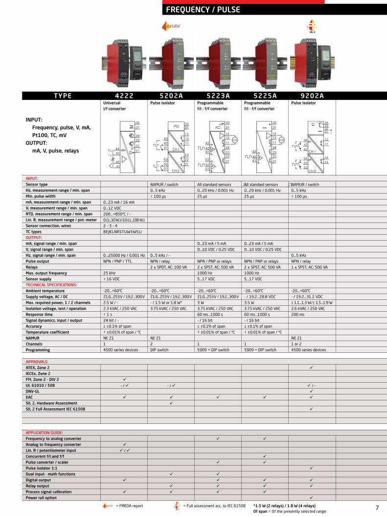
ISOLATORS
3103Isolated repeater
0...23 mA / 1:1
0...23 mA / 1:1
≤ 600 Ω
-25...+70°C
- / 16.8...31.2 VDC
0.65 W
2.5 kVAC / 250 VAC
< 7 ms
Analog signal chain
< ±0.05% of span
< ±0.01% of span / °C
NE 21
1
No
3104Isolated converter
0...23 mA / 16 mA
0...10.25 VDC / 4 VDC
- / > 17 V
0...23 mA / 16 mA
≤ 600 Ω
0...10 VDC / 4 VDC
≥ 10 kΩ
-25...+70°C
- / 16.8...31.2 VDC
1.2 W
2.5 kVAC / 250 VAC
< 7 ms
Analog signal chain
< ±0.05% of span
< ±0.01% of span / °C
NE 21
1
DIP switch
TYPE
INPUT: mA, V, potentiometer
OUTPUT: mA, V
INPUT: mA, measurement range / min. span V, measurement range / min. span Reference voltage / 2-wire supply
OUTPUT: mA, signal range / min. span Load (@ current output) V, signal range / min. span Load (@ voltage output)
TECHNICAL SPECIFICATIONS: Ambient temperature Supply voltage, AC / DC Max. required power* Isolation voltage, test / operation Response time Signal dynamics, input / output Accuracy Temperature coefficient NAMUR ChannelsProgramming
APPROVALS:ATEX, Zone 2 IECEx, Zone 2 FM, Zone 2 - DIV 2 UL 61010 / 508 DNV-GL EAC
APPLICATION GUIDE:Signal repeaterSignal converter Signal splittermA / V bipolar input4...20 mA Tx inputBuffered voltage outputmA / V outputActive / passive mA outputMounting in Zone 2 / Div 2Power rail option
3105Isolated converter
0...23 mA / 16 mA
0...10.25 VDC / 4 VDC
0...23 mA / 16 mA
≤ 600 Ω
0...10 VDC / 4 VDC
≥ 10 kΩ
0...+70°C
- / 16.8...31.2 VDC
0.8 W
2.5 kVAC / 250 VAC
< 7 ms
Analog signal chain
< ±0.2% of span
< ±0.015% of span / °C
NE 21
1
DIP switch
3108Isolated repeater / splitter
0...23 mA / 1:1
0...23 mA / 1:1
≤ 300 Ω per channel
-25...+70°C
- / 16.8...31.2 VDC
0.75 W
2.5 kVAC / 250 VAC
< 7 ms
Analog signal chain
< ±0.05% of span
< ±0.01% of span / °C
NE 21
1
No
3109Isolated converter / splitter
0...23 mA / 16 mA
0...10.25 VDC / 4 VDC
- / > 17 V
0...23 mA / 16 mA
≤ 300 Ω per channel
0...10 VDC / 4 VDC
≥ 10 kΩ
-25...+70°C
- / 16.8...31.2 VDC
1.2 W
2.5 kVAC / 250 VAC
< 7 ms
Analog signal chain
< ±0.05% of span
< ±0.01% of span / °C
NE 21
1
DIP switch
3117Bipolar isolated converter
-23...+23 mA
±5 and ±10 VDC
0...23 mA / 16 mA
≤ 600 Ω
0...10 VDC / 4 VDC
≥ 10 kΩ
-25...+70°C
- / 16.8...31.2 VDC
0.8 W
2.5 kVAC / 250 VAC
< 7 ms
Analog signal chain
< ±0.05% of span
< ±0.01% of span / °C
NE 21
1
DIP switch
* = @ 24 VDC Of span = Of the presently selected range
9
5
6
+
mA
7
8
1
2
1
2
+
mA
4
3
2
1
mATx
5
6
+4
3
2
1
mA
7
8
+
+
+
mA
1
2
1
2mA
mA
87 +
4
3± mA± V
V
V
1
2
5
6
+
mA
2
1
+
mA
+
C O M M U N I C AT I O N F O U N D AT I O N
/ - / - / - - / - /
/
/ - / / -
/ / - / - / / - / -
/ - / - - / / / / -
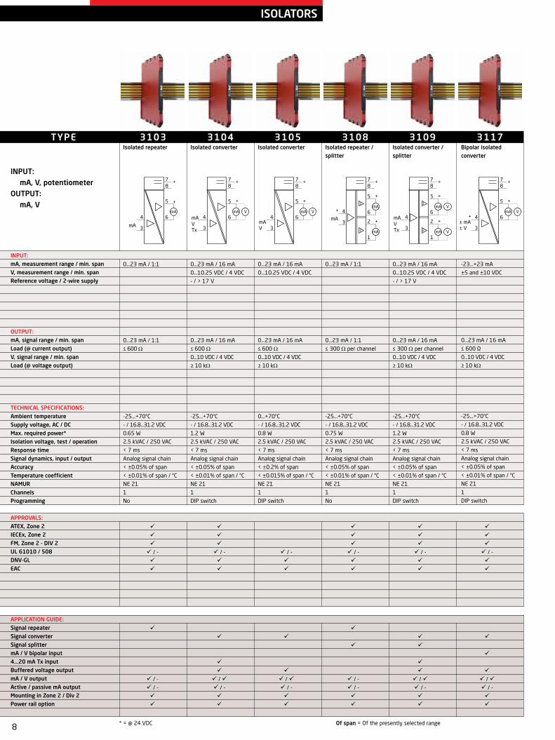
3118Bipolar isolated converter / splitter
-23...+23 mA
±5 and ±10 VDC
0...23 mA / 16 mA
≤ 300 Ω per channel
0...10 VDC / 4 VDC
≥ 10 kΩ
-25...+70°C
- / 16.8...31.2 VDC
*0.8 W / -
2.5 kVAC / 250 VAC
< 7 ms
Analog signal chain
< ±0.05% of span
< ±0.01% of span / °C
NE 21
1
DIP switch
3185Loop-powered isolator
0...23 mA / 1:1
0...23 mA / 1:1
≤ 600 Ω
-25...+70°C
≤ 1.25 V + (0.015 x Vout.)
30 mW per channel
2.5 kVAC / 250 VAC
< 5 ms
Analog signal chain
< ±0.1% of span
< ±0.01% of span / °C
NE 21
1 or 2
No
5104ARepeater / power supply
0...23 mA / 16 mA
0...10 VDC / 8 VDC
20% of selec. max. value
- / > 17.1 VDC
0...23 mA / 16 mA
≤ 600 Ω
0...10 VDC / 0.8 VDC
≥ 500 kΩ
20% of selec. max. value
-20...+60°C
21.6...253 V / 19.2...300 V
2.0 W / 2.8 W
3.75 kVAC / 250 VAC
< 25 ms
Analog signal chain
≤ ±0.1% of span
< ±0.01% of span / °C
NE 21
1 or 2
DIP switch
31862-wire transmitter isolator
3.5...23 mA / 1:1
- / Vloop-2.5 VDC
3.5...23 mA / 1:1
-25...+70°C
- / 6...35 VDC
50 mW per channel
2.5 kVAC / 250 VAC
< 5 ms
Analog signal chain
< ±0.05% of span
< ±0.01% of span / °C
NE 21
1 or 2
No
* = @ 24 VDC Of span = Of the presently selected range
TYPE
INPUT: mA, mV, V, HART communi cation
OUTPUT: mA, V, HART communication
INPUT: mA, measurement range / min. span V, measurement range / min. span Max. offset Reference voltage / 2-wire supply
OUTPUT: mA, signal range / min. span Load (@ current output) V, signal range / min. span Load (@ voltage output) Max. offset
TECHNICAL SPECIFICATIONS: Ambient temperature Supply voltage, AC / DC Max. required power, 1 / 2 channels Isolation voltage, test / operation Response time Signal dynamics, input / output Accuracy Temperature coefficient NAMUR Channels Programming
APPROVALS:ATEX, Zone 2 IECEx, Zone 2 FM, Zone 2 - DIV 2 UL 61010 / 508 DNV-GL EAC
APPLICATION GUIDE:Signal repeaterSignal converter Signal splittermA / V bipolar input4...20 mA Tx input Buffered voltage outputActive / passive input signal mA / V outputActive / passive mA outputMounting in Zone 2 / Div 2Power rail option
5106AHART transparent repeater
3.5...23 mA / 1:1
- / > 17 VDC
3.5...23 mA / 1:1
≤ 600 Ω
-20...+60°C
21.6...253 V / 19.2...300 V
2.0 W / 2.8 W
3.75 kVAC / 250 VAC
< 25 ms
Analog signal chain
≤ ±0.1% of span
< ±0.01% of span / °C
NE 21
1 or 2
DIP switch
6185Loop-powered isolator
0...23 mA / 1:1
0...23 mA / 1:1
≤ 600 Ω
-20...+60°C
- / ≤ 1.8 VDC
40 mW per channel
2 kVAC / -
< 4 ms
Analog signal chain
≤ ±0.1% of span
< ±0.01% of span / °C
1, 2 or 4
No
ISOLATORS
10
mATx
mATx
C O M M U N I C AT I O N F O U N D AT I O N C O M M U N I C AT I O N F O U N D AT I O N
/ - / - / -
/ / -
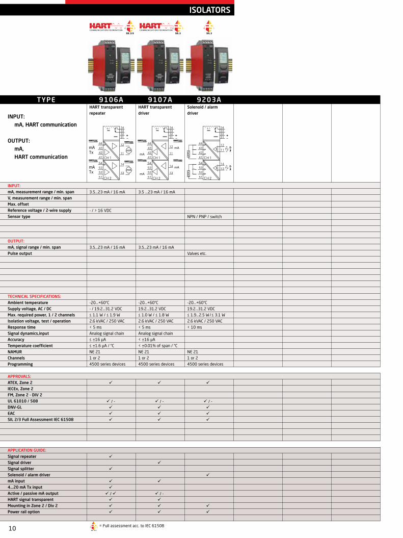
9106AHART transparent repeater
3.5...23 mA / 16 mA
- / > 16 VDC
3.5...23 mA / 16 mA
-20...+60°C
- / 19.2...31.2 VDC
≤ 1.1 W / ≤ 1.9 W
2.6 kVAC / 250 VAC
< 5 ms
Analog signal chain
≤ ±16 μA
≤ ±1.6 μA / °C
NE 21
1 or 2
4500 series devices
9107AHART transparent driver
3.5 ...23 mA / 16 mA
3.5...23 mA / 16 mA
-20...+60°C
19.2...31.2 VDC
≤ 1.0 W / ≤ 1.8 W
2.6 kVAC / 250 VAC
< 5 ms
Analog signal chain
< ±16 µA
< ±0.01% of span / °C
NE 21
1 or 2
4500 series devices
9203ASolenoid / alarm driver
NPN / PNP / switch
Valves etc.
-20...+60°C
19.2...31.2 VDC
≤ 1.9...2.5 W / ≤ 3.1 W
2.6 kVAC / 250 VAC
< 10 ms
NE 21
1 or 2
4500 series devices
ISOLATORS
TYPE
INPUT: mA, HART communication
OUTPUT: mA, HART communication
INPUT: mA, measurement range / min. span V, measurement range / min. span Max. offset Reference voltage / 2-wire supply Sensor type
OUTPUT: mA, signal range / min. span Pulse output
TECHNICAL SPECIFICATIONS: Ambient temperature Supply voltage, AC / DC Max. required power, 1 / 2 channels Isolation voltage, test / operation Response time Signal dynamics,input Accuracy Temperature coefficient NAMUR Channels Programming
APPROVALS:ATEX, Zone 2 IECEx, Zone 2 FM, Zone 2 - DIV 2 UL 61010 / 508 DNV-GL EAC SIL 2/3 Full Assessment IEC 61508
APPLICATION GUIDE:Signal repeaterSignal driverSignal splitterSolenoid / alarm drivermA input4...20 mA Tx inputActive / passive mA outputHART signal transparentMounting in Zone 2 / Div 2Power rail option
= Full assessment acc. to IEC 61508

11
8
5
6
7 +
+
3
2
mA V+
8
5
6
7 +
+
mA4
3
2
1
+
8
5
6
7 +
+
mA V4
3
2
1
8
5
6
7 +
+
3
2
mA V+
8
5
6
7 +
+
mA V4
3
2
1
C O M M U N I C AT I O N F O U N D AT I O N
/ - / - / - / - / -
- / / - / - / - - / / - / - / - / / -
/ / / / / -
/ / / / /
3113HART 7 temperature converter
-200...+850°C / 10°C
2 - 3 - 4
J & K
Internal / external
0...23 mA / 16 mA
≤ 600 Ω
-25...70°C
16.8...31.2 VDC
0.7 W
2.5 kVAC / 250 VAC
< 60 ms
23 bit / 18 bit
≤ ±0.05% of span
< ±0.01% of span / °C
NE 21, NE 43
1
DIP switch / HART
3112Pt100 converter - isolated
-200...+850°C / 10°C
2 -3 - 4
0...23 mA / 16 mA
≤ 600 Ω
0...10 VDC / 4 VDC
≥ 10 kΩ
-25...70°C
16.8...31.2 VDC
0.7 W
2.5 kVAC / 250 VAC
< 30 ms
23 bit / 18 bit
≤ ±0.05% of span
< ±0.01% of span / °C
NE 21, NE 43
1
DIP switch
3111TC converter - isolated
J & K
Internal / external
0...23 mA / 16 mA
≤ 600 Ω
0...10 VDC / 4 VDC
≥ 10 kΩ
-25...70°C
16.8...31.2 VDC
0.7 W
2.5 kVAC / 250 VAC
< 30 ms
23 bit / 18 bit
≤ ±0.05% of span
< ±0.01% of span / °C
NE 21, NE 43
1
DIP switch
3102Pt100 converter
-200...+850°C / 10°C
2 - 3 - 4
0...23 mA / 16 mA
≤ 600 Ω
0...10 VDC / 4 VDC
≥ 10 kΩ
-25...70°C
16.8...31.2 VDC
0.52 W
< 30 ms
23 bit / 18 bit
≤ ±0.1% of span
< ±0.01% of span / °C
NE 21, NE 43
1
DIP switch
3101TC converter
J & K
Internal
0...23 mA / 16 mA
≤ 600 Ω
0...10 VDC / 4 VDC
≥ 10 kΩ
-25...70°C
16.8...31.2 VDC
0.52 W
< 30 ms
23 bit / 18 bit
≤ ±0.1% of span
< ±0.01% of span / °C
NE 21, NE 43
1
DIP switch
TEMPERATURE TRANSMITTERS
TYPE
INPUT: RTD, linear resistance, TC, mV, mA, potentiometer
OUTPUT: mA, HART communication
INPUT: RTD, measurement range / min. span Lin. R, measurement range / min. span Sensor connection, wires TC types Max. offset Cold junction compensation
OUTPUT: mA, signal range / min. span Load (@ current output) V, signal range / min. span Load (@ voltage output)
TECHNICAL SPECIFICATIONS: Ambient temperature Supply voltage, DC Max. required power* Isolation voltage, test / operation Response time Signal dynamics, input / output Accuracy Temperature coefficient NAMUR Channels Programming
APPROVALS:ATEX, Zone 2 IECEx, Zone 2 FM, Zone 2 - DIV 2 UL 61010 / 508 DNV-GL EAC
APPLICATION GUIDE:RTD / TC / mV input mA / V outputLoop-poweredGalvanically isolatedHART protocolMounting in Zone 2 / DIV 2Process signal calibrationPower rail option
* = @ 24 VDC Of span = Of the presently selected range

12
5
6
4
3
2
1
+
+
mA
5
6
4
3
2
1
+
mA
5
6
4
3
2
1
+
+
mA
C O M M U N I C AT I O N F O U N D AT I O N
/ - / - / -
/ / - / - / - / / -
/ - / - / -
/ / /
3331Temperature converter, loop-powered - isolated
-200...+850°C / 10°C
2 - 3 - 4
J & K
Internal / external
3.5...23 mA / 16 mA
≤ (Vsupply-5.5) / 0.023 [Ω]
-25...70°C
5.5...35 VDC
0.8 W
2.5 kVAC / 250 VAC
< 30 ms
23 bit / 18 bit
≤ ±0.05% of span
< ±0.01% of span / °C
NE 21, NE 43
1
DIP switch
3333Pt100 converter, loop-powered
-200...+850°C / 10°C
2 - 3 - 4
3.5...23 mA / 16 mA
≤ (Vsupply-3.3) / 0.023 [Ω]
-25...70°C
3.3...35 VDC
0.8 W
< 30 ms
23 bit / 18 bit
≤ ±0.1% of span
< ±0.01% of span / °C
NE 21, NE 43
1
DIP switch
3337HART 7 temperature converter, loop-powered
-200...+850°C / 10°C
2 - 3 - 4
J & K
Internal / external
3.5...23 mA / 16 mA
≤ (Vsupply-6.2) / 0.023 [Ω]
-25...70°C
6.2...35 VDC
0.8 W
2.5 kVAC / 250 VAC
< 60 ms
23 bit / 18 bit
≤ ±0.05% of span
< ±0.01% of span / °C
NE 21, NE 43
1
DIP switch / HART
TEMPERATURE TRANSMITTERS
TYPE INPUT:
RTD, linear resistance, TC, mV
OUTPUT: mA, V, HART communication
INPUT: RTD, measurement range / min. span Lin. R, measurement range / min. span Sensor connection, wires TC types Max. offset Cold junction compensation
OUTPUT: mA, signal range / min. span Load (@ current output)
TECHNICAL SPECIFICATIONS: Ambient temperature Supply voltage, DC Max. required power Isolation voltage, test / operation Response time Signal dynamics, input / output Accuracy Temperature coefficient NAMUR Channels Programming
APPROVALS: ATEX, Zone 2 IECEx, Zone 2 FM, Zone 2 - DIV 2 UL 61010 / 508 DNV-GL EAC
APPLICATION GUIDE:RTD / TC / mV input mA / V outputLoop-poweredGalvanically isolatedHART protocolMounting in Zone 2 / DIV 2Process signal calibration
Of span = Of the presently selected range

13
R
C O M M U N I C AT I O N F O U N D AT I O N
R
C O M M U N I C AT I O N F O U N D AT I O N
R
/ / / - / - / - / - - / / / / / / / - / - / - / - / -
/ - / - / - / - / - / -
5335A2-wire transmitter with HART 5 protocol
-800...+800 mV / 2.5 mV
-200...+850°C / 10°C
0...7000 Ω / 25 Ω
2 - 3 - 4
BEJKLNRSTUW3W5
50% of selec. max. value
Internal / external
3.5...23 mA / 16 mA
-40...+85°C
8...35 VDC
0.8 W
1500 VAC / 50 V
1...60 s
22 bit / 16 bit
≤ ±0.05% of span
< ±0.005% of span / °C
NE 21, NE 43, NE89
1
5909 / HART 5
5331A2-wire programmable transmitter
-12...800 mV / 5 mV
-200...+850°C / 25°C
0...5000 Ω / 30 Ω
2 - 3 - 4
BEJKLNRSTUW3W5Lr
50% of selec. max. value
Internal / external
3.5...23 mA / 16 mA
-40...+85°C
7.2...35 VDC
0.8 W
1500 VAC / 50 V
1...60 s
20 bit / 16 bit
≤ ±0.05% of span
< ±0.01% of span / °C
NE 21, NE 43
1
5909
5332A2-wire programmable RTD transmitter
-200...+850°C / 25°C
0...5000 Ω / 30 Ω
2 - 3 - 4
50% of selec. max. value
3.5...23 mA / 16 mA
-40...+85°C
7.2...35 VDC
0.8 W
1...60 s
20 bit / 16 bit
≤ ±0.05% of span
< ±0.01% of span / °C
NE 43
1
5909
5333A2-wire programmable transmitter
-200...+850°C / 25°C
0...10 kΩ / 30 Ω
2 - 3
50% of selec. max. value
3.5...23 mA / 16 mA
-40...+85°C
8...35 VDC
0.8 W
0.33...60 s
19 bit / 16 bit
≤ ±0.1% of span
< ±0.01% of span / °C
NE 43
1
5909
TEMPERATURE TRANSMITTERS
5337A2-wire transmitter with HART 7 protocol
-800...+800 mV / 2.5 mV
-200...+850°C / 10°C
0...7000 Ω / 25 Ω
2 - 3 - 4
BEJKLNRSTUW3W5
50% of selec. max. value
Internal / external
3.5...23 mA / 16 mA
-40...+85°C
8...35 VDC
0.8 W
1500 VAC / 50 V
1...60 s
22 bit / 16 bit
≤ ±0.05% of span
< ±0.005% of span / °C
NE 21, NE 43, NE89
1
5909 / HART 7 / HART 5
TYPE
INPUT: RTD, linear resistance, TC, mV, potentiometer
OUTPUT: mA, HART communication
INPUT:mV, measurement range / min. span RTD, measurement range / min. spanLin. R, measurement range / min. spanPotentiometer Sensor connection, wiresTC typesMax. offset Cold junction compensation
OUTPUT:mA, signal range / min. span
TECHNICAL SPECIFICATIONS: Ambient temperatureSupply voltage, DCMax. required powerIsolation voltage, test / operationResponse timeSignal dynamics, input / outputAccuracyTemperature coefficientNAMUR Channels Programming
APPROVALS:ATEX, Zone 2 IECEx, Zone 2 CSA, Zone 2 - DIV 2 FM, Zone 2 - DIV 2 INMETRO NEPSI DNV-GL EAC SIL 2, Hardware Assessment
APPLICATION GUIDE:RTD / TC / mV input Lin. R / potentiometer inputDual input (4 terminals)Custom sensor linearizationmA outputLoop-poweredGalvanically isolatedHART protocolMounting in Zone 2 / DIV 2Process signal calibration
5334A2-wire programmable transmitter
-12...150 mV / 5 mV
BEJKLNRSTUW3W5Lr
50% of selec. max. value
Internal
3.5...23 mA / 16 mA
-40...+85°C
7.2...35 VDC
0.8 W
1500 VAC / 50 V
1...60 s
18 bit / 16 bit
≤ ±0.05% of span
< ±0.01% of span / °C
NE 21, NE 43
1
5909
= FMEDA report Of span = Of the presently selected range
14
C O M M U N I C AT I O N F O U N D AT I O N
8
7
6
5
4
3
9
1
2
mA
+
RTDTC
Lin. RPot.mV
RTDTC
Lin. RPot.mV
/ - - / ()
/
/ / / / / / /
/ - / /
TYPE
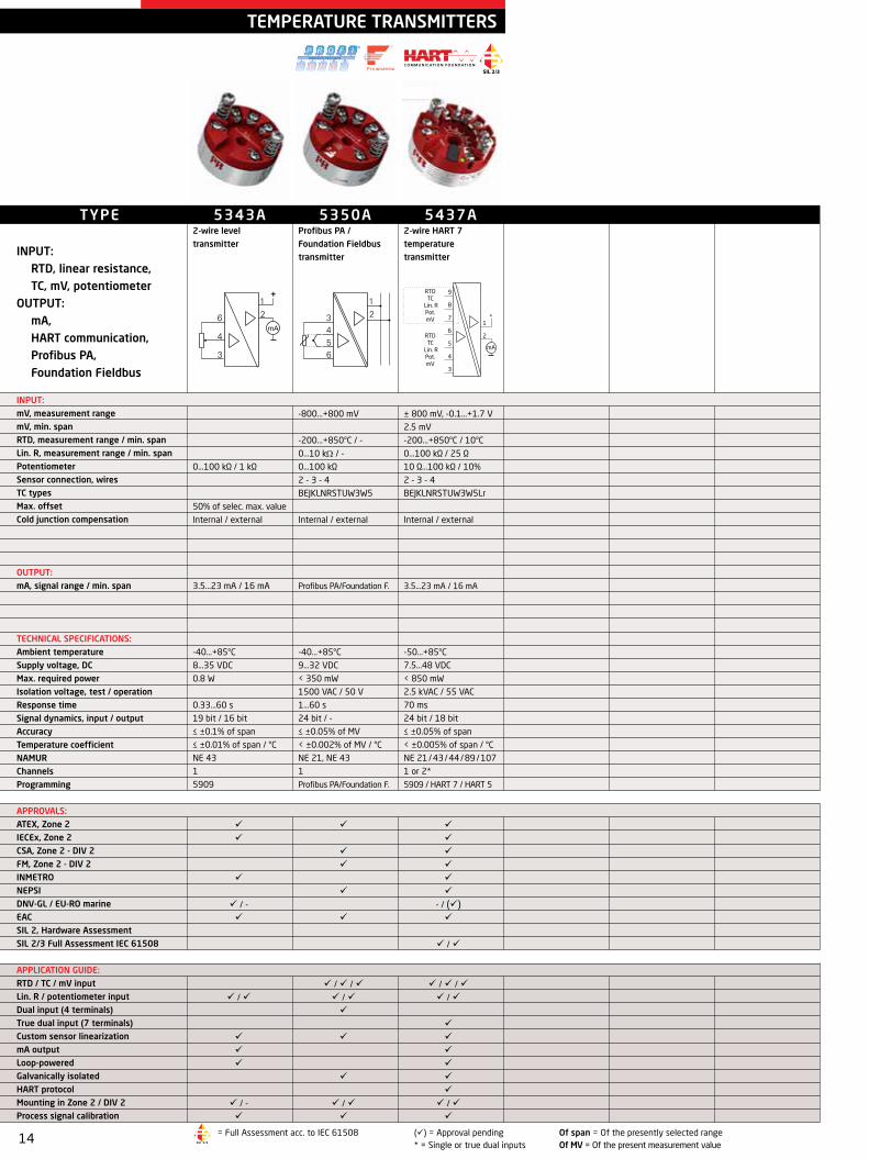
INPUT: RTD, linear resistance, TC, mV, potentiometer
OUTPUT: mA, HART communication, Profibus PA, Foundation Fieldbus
INPUT:mV, measurement range mV, min. span RTD, measurement range / min. spanLin. R, measurement range / min. spanPotentiometer Sensor connection, wiresTC typesMax. offset Cold junction compensation
OUTPUT:mA, signal range / min. span
TECHNICAL SPECIFICATIONS: Ambient temperatureSupply voltage, DCMax. required powerIsolation voltage, test / operationResponse timeSignal dynamics, input / outputAccuracyTemperature coefficientNAMUR Channels Programming
APPROVALS:ATEX, Zone 2 IECEx, Zone 2 CSA, Zone 2 - DIV 2 FM, Zone 2 - DIV 2 INMETRO NEPSI DNV-GL / EU-RO marine EAC SIL 2, Hardware AssessmentSIL 2/3 Full Assessment IEC 61508
APPLICATION GUIDE:RTD / TC / mV input Lin. R / potentiometer inputDual input (4 terminals)True dual input (7 terminals)Custom sensor linearizationmA outputLoop-poweredGalvanically isolatedHART protocolMounting in Zone 2 / DIV 2Process signal calibration
TEMPERATURE TRANSMITTERS
5343A2-wire level transmitter
0...100 kΩ / 1 kΩ
50% of selec. max. value
Internal / external
3.5...23 mA / 16 mA
-40...+85°C
8...35 VDC
0.8 W
0.33...60 s
19 bit / 16 bit
≤ ±0.1% of span
≤ ±0.01% of span / °C
NE 43
1
5909
5350AProfibus PA / Foundation Fieldbus transmitter
-800...+800 mV
-200...+850°C / -
0...10 kΩ / - 0...100 kΩ
2 - 3 - 4
BEJKLNRSTUW3W5
Internal / external
Profibus PA/Foundation F.
-40...+85°C
9...32 VDC
< 350 mW
1500 VAC / 50 V
1...60 s
24 bit / -
≤ ±0.05% of MV
< ±0.002% of MV / °C
NE 21, NE 43
1
Profibus PA/Foundation F.
= Full Assessment acc. to IEC 61508 () = Approval pending Of span = Of the presently selected range * = Single or true dual inputs Of MV = Of the present measurement value
5437A2-wire HART 7 temperature transmitter
± 800 mV, -0.1...+1.7 V
2.5 mV
-200...+850°C / 10°C
0...100 kΩ / 25 Ω
10 Ω...100 kΩ / 10%
2 - 3 - 4
BEJKLNRSTUW3W5Lr
Internal / external
3.5...23 mA / 16 mA
-50...+85°C
7.5...48 VDC
< 850 mW
2.5 kVAC / 55 VAC
70 ms
24 bit / 18 bit
≤ ±0.05% of span
< ±0.005% of span / °C
NE 21 / 43 / 44 / 89 / 107
1 or 2*
5909 / HART 7 / HART 5

15
R
C O M M U N I C AT I O N F O U N D AT I O N
R
C O M M U N I C AT I O N F O U N D AT I O N
R
/ / / - / - - / / / / / / / / / - / - / - / - /
/ - / - / - / - / - /
6331A2-wire programmable transmitter
-12...800 mV / 5 mV
-200...+850°C / 25°C
0...5000 Ω / 30 Ω
2 - 3 - 4
BEJKLNRSTUW3W5Lr
50% of selec. max. value
Internal / external
3.5...23 mA / 16 mA
-40...+85°C
7.2...35 VDC
0.8 W / 1.6 W
1500 VAC / 50 V
1...60 s
20 bit / 16 bit
≤ ±0.05% of span
< ±0.01% of span / °C
NE 21, NE 43
1 or 2
5909
6333A2-wire programmable transmitter
-200...+850°C / 25°C
0...10 kΩ / 30 Ω
2 - 3
50% of selec. max. value
3.5...23 mA / 16 mA
-40...+85°C
8...35 VDC
0.8 W / 1.6 W
0.33...60 s
19 bit / 16 bit
≤ ±0.1% of span
< ±0.01% of span / °C
NE 43
1 or 2
5909
TEMPERATURE TRANSMITTERS
6334A2-wire programmable transmitter
-12...+150 mV / 5 mV
BEJKLNRSTUW3W5Lr
50% of selec. max. value
Internal
3.5...23 mA / 16 mA
-40...+85°C
7.2...35 VDC
0.8 W / 1.6 W
1500 VAC / 50 V
1...60 s
18 bit / 16 bit
≤ ±0.05% of span
< ±0.01% of span / °C
NE 21, NE 43
1 or 2
5909
TYPE
INPUT: RTD, linear resistance, TC, mV, mA, potentiometer
OUTPUT: mA, HART communication, Profibus PA, Foundation Fieldbus
INPUT: mA, measurement range / min. span mV, measurement range / min. span RTD, measurement range / min. span Lin. R, measurement range / min. span Potentiometer Sensor connection, wires TC types Max. offset Cold junction compensation
OUTPUT: mA, signal range / min. span
TECHNICAL SPECIFICATIONS: Ambient temperature Supply voltage, DC Max. required power, 1 / 2 channels Isolation voltage, test / operation Response time Signal dynamics, input / output Accuracy Temperature coefficient NAMUR Channels Programming
APPROVALS:ATEX, Zone 2 IECEx, Zone 2 CSA, Zone 2 - DIV 2 FM, Zone 2 - DIV 2 UL 61010 / 508 DNV-GL EAC SIL 2, Hardware Assessment SIL 2 Full Assessment IEC 61508
APPLICATION GUIDE:RTD / TC / mV input Lin. R / potentiometer inputDual input (4 terminals)Custom sensor linearizationmA outputLoop-poweredGalvanically isolatedHART protocolMounting in Zone 2 / DIV 2Process signal calibration
6335A2-wire HART 5 transmitter
-800...+800 mV / 2.5 mV
-200...+850°C / 10°C
0...7000 Ω / 25 Ω
2 - 3 - 4
BEJKLNRSTUW3W5
50% of selec. max. value
Internal / external
3.5...23 mA / 16 mA
-40...+85°C
8...35 VDC
0.8 W / 1.6 W
1500 VAC / 50 V
1...60 s
22 bit / 16 bit
≤ ±0.05% of span
< ±0.005% of span / °C
NE 21, NE 43, NE 89
1 or 2
5909 / HART 5
6337A2-wire HART 7 transmitter
-800...+800 mV / 2.5 mV
-200...+850°C / 10°C
0...7000 Ω / 25 Ω
2 - 3 - 4
BEJKLNRSTUW3W5
50% of selec. max. value
Internal / external
3.5...23 mA / 16 mA
-40...+85°C
8...35 VDC
0.8 W / 1.6 W
1500 VAC / 50 V
1...60 s
22 bit / 16 bit
≤ ±0.05% of span
< ±0.005% of span / °C
NE 21, NE 43, NE 89
1 or 2
5909 / HART 7 / HART 5
6350AProfibus PA / Foundation Fieldbus transmitter
-100...+100 mA / -
-800...+800 mV / -
-200...+850°C / -
0...10 kΩ / - 0...100 kΩ / -
2 - 3 - 4
BEJKLNRSTUW3W5
Internal / external
Profibus PA/Foundation F.
-40...+85°C
9...32 VDC
< 350 mW per channel
1500 VAC / 50 V
1...60 s
24 bit / -
≤ ±0.05% of MV
< ±0.002% of MV / °C
NE 21, NE 43
1 or 2
Profibus PA/Foundation F.
= FMEDA report Of span = Of the presently selected range Of MV = Of the present measurement value

16
C O M M U N I C AT I O N F O U N D AT I O N
R
R
RTDTC
Lin. RPot.mV
RTDTC
Lin. RPot.mV
IN 1
IN 2
12
11
22
21
C O M M U N I C AT I O N F O U N D AT I O N
/
/ -
- / () - / / -
/ / -
/ / / / / / -
/ / -
TEMPERATURE TRANSMITTERS
TYPE
INPUT: RTD, linear resistance, TC, mV, mA, potentiometer
OUTPUT: mA, HART communication
INPUT: mA, measurement range / min. span mV, measurement range mV, min. spanRTD, measurement range / min. spanLin. R, measurement range / min. spanPotentiometerSensor connection, wiresTC types Cold junction compensation
OUTPUT: mA, signal range / min. span
TECHNICAL SPECIFICATIONS: Ambient temperature Supply voltage, DC Max. required power, 1 / 2 channels Isolation voltage, test / operation Response time Signal dynamics, input / output Accuracy Temperature coefficient NAMUR Channels Programming
APPROVALS:ATEX, Zone 2 IECEx, Zone 2 CSA, Zone 2 - DIV 2 FM, Zone 2 - DIV 2 INMETRO / NEPSI UL 61010 / 508 DNV-GL / EU-RO marine EAC SIL 2, Hardware Assessment SIL 2/3 Full Assessment IEC 61508
APPLICATION GUIDE:RTD / TC / mV input Lin. R / potentiometer inputDual input (4 terminals)True dual input (8 terminals) Custom sensor linearizationmA outputLoop-poweredGalvanically isolatedHART protocolProcess signal calibrationPower rail option
6437A2-wire HART 7 temperature transmitter
± 800 mV, -0.1...+1.7 V
2.5 mV
-200...+850°C / 10°C
0...100 kΩ / 25 Ω
10 Ω...100 kΩ / 10%
2 - 3 - 4
BEJKLNRSTUW3W5Lr
Internal / external
3.5...23 mA / 16 mA
-50...+85°C
7.5...48 VDC
< 850 mW / -
2.5 kVAC / 55 VAC
70 ms
24 bit / 18 bit
≤ ±0.05% of span
< ±0.005% of span / °C
NE 21 / 43 / 44 / 89 / 107
1 or 2*
5909 / HART 7 / HART 5
7501Field mounted HART temperature transmitter
-800...+800 mV
2.5 mV
-200...+850°C / 10°C
0...7000 Ω / 25 Ω
2 - 3 - 4
BEJKLNRSTUW3W5
Internal / external
3.5...23 mA / 16 mA
-40...+85°C
10 / 12...35 VDC
1500 VAC / 50 VAC
22 bit / 16 bit
1...60 s
≤ ±0.05% of span
< ±0.005% of span / °C
NE 21, NE 43
1
LOI / HART
= Full assessment acc. to IEC 61508 = FMEDA report LOI = Local operator interface () = Approval pending * = Single or true dual inputs Of span = Of the presently selected range
9113ATemperature / mA converter
0...23 mA / 16 mA
-200...+850°C / 25°C
2 - 3 - 4
BEJKLNRSTUW3W5Lr
Internal / external
0...23 mA / 16 mA
-20...+60°C
19.2...31.2 VDC
≤ 0.8 W / ≤ 1.4 W
2.6 kVAC / 250 VAC
0.4 / 1...60 s
24 bit / 16 bit
≤ ±0.1% of span
< ±0.01% of span / °C
NE 21, NE 43
1 or 2
4500 series devices
17
R
C O M M U N I C AT I O N F O U N D AT I O N
R
C O M M U N I C AT I O N F O U N D AT I O N
R
/ / / - / - / - / - - / / / / / / / - / - / - / - / -
I.S. TEMPERATURE TRANSMITTERS
TYPE
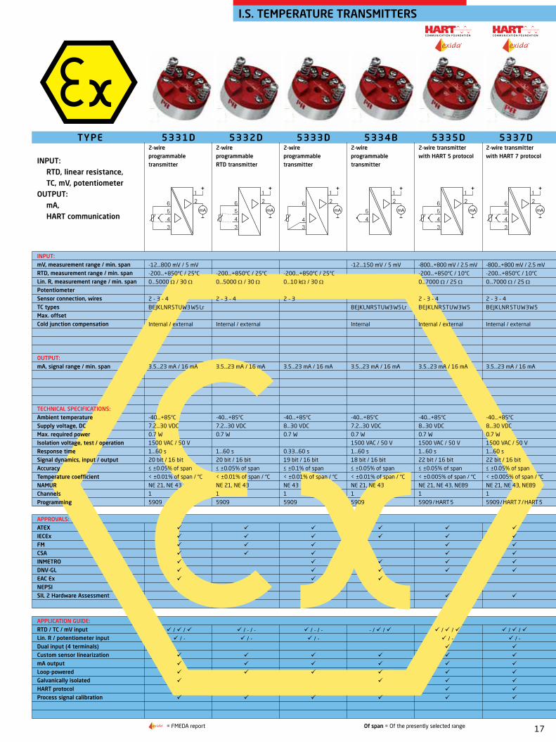
INPUT: RTD, linear resistance, TC, mV, potentiometer
OUTPUT: mA, HART communication
INPUT:mV, measurement range / min. span RTD, measurement range / min. spanLin. R, measurement range / min. spanPotentiometer Sensor connection, wiresTC types Max. offset Cold junction compensation
OUTPUT:mA, signal range / min. span
TECHNICAL SPECIFICATIONS: Ambient temperatureSupply voltage, DCMax. required powerIsolation voltage, test / operationResponse timeSignal dynamics, input / outputAccuracyTemperature coefficientNAMUR ChannelsProgramming
APPROVALS:ATEX IECEx FM CSA INMETRO DNV-GL EAC Ex NEPSI SIL 2 Hardware Assessment
APPLICATION GUIDE:RTD / TC / mV input Lin. R / potentiometer inputDual input (4 terminals)Custom sensor linearization mA outputLoop-poweredGalvanically isolatedHART protocolProcess signal calibration
5332D2-wire programmable RTD transmitter
-200...+850°C / 25°C
0...5000 Ω / 30 Ω
2 - 3 - 4
Internal / external
3.5...23 mA / 16 mA
-40...+85°C
7.2...30 VDC
0.7 W
1...60 s
20 bit / 16 bit
≤ ±0.05% of span
< ±0.01% of span / °C
NE 21, NE 43
1
5909
5331D2-wire programmable transmitter
-12...800 mV / 5 mV
-200...+850°C / 25°C
0...5000 Ω / 30 Ω
2 - 3 - 4
BEJKLNRSTUW3W5Lr
Internal / external
3.5...23 mA / 16 mA
-40...+85°C
7.2...30 VDC
0.7 W
1500 VAC / 50 V
1...60 s
20 bit / 16 bit
≤ ±0.05% of span
< ±0.01% of span / °C
NE 21, NE 43
1
5909
5333D2-wire programmable transmitter
-200...+850°C / 25°C
0...10 kΩ / 30 Ω
2 - 3
3.5...23 mA / 16 mA
-40...+85°C
8...30 VDC
0.7 W
0.33...60 s
19 bit / 16 bit
≤ ±0.1% of span
< ±0.01% of span / °C
NE 43
1
5909
5335D2-wire transmitter with HART 5 protocol
-800...+800 mV / 2.5 mV
-200...+850°C / 10°C
0...7000 Ω / 25 Ω
2 - 3 - 4
BEJKLNRSTUW3W5
Internal / external
3.5...23 mA / 16 mA
-40...+85°C
8...30 VDC
0.7 W
1500 VAC / 50 V
1...60 s
22 bit / 16 bit
≤ ±0.05% of span
< ±0.005% of span / °C
NE 21, NE 43, NE89
1
5909 / HART 5
5334B2-wire programmable transmitter
-12...150 mV / 5 mV
BEJKLNRSTUW3W5Lr
Internal
3.5...23 mA / 16 mA
-40...+85°C
7.2...30 VDC
0.7 W
1500 VAC / 50 V
1...60 s
18 bit / 16 bit
≤ ±0.05% of span
< ±0.01% of span / °C
NE 21, NE 43
1
5909
5337D2-wire transmitter with HART 7 protocol
-800...+800 mV / 2.5 mV
-200...+850°C / 10°C
0...7000 Ω / 25 Ω
2 - 3 - 4
BEJKLNRSTUW3W5
Internal / external
3.5...23 mA / 16 mA
-40...+85°C
8...30 VDC
0.7 W
1500 VAC / 50 V
1...60 s
22 bit / 16 bit
≤ ±0.05% of span
< ±0.005% of span / °C
NE 21, NE 43, NE89
1
5909 / HART 7 / HART 5
= FMEDA report Of span = Of the presently selected range

18
8
7
6
5
4
3
9
1
2
mA
+
RTDTC
Lin. RPot.mV
RTDTC
Lin. RPot.mV
C O M M U N I C AT I O N F O U N D AT I O N
/ - - / ()
/
/ / / / / / /
/
TYPE
INPUT: RTD, linear resistance, TC, mV, potentiometer
OUTPUT: mA, HART communication, Profibus PA, Foundation Fieldbus
INPUT:mV, measurement range mV, min. span RTD, measurement range / min. spanLin. R, measurement range / min. spanPotentiometer Sensor connection, wiresTC typesMax. offset Cold junction compensation
OUTPUT:mA, signal range / min. span
TECHNICAL SPECIFICATIONS: Ambient temperatureSupply voltage, DCMax. required powerIsolation voltage, test / operationResponse timeSignal dynamics, input / outputAccuracyTemperature coefficientNAMUR ChannelsProgramming
APPROVALS:ATEX IECEx FM CSA INMETRO DNV-GL / EU-RO marine EAC Ex NEPSI SIL 2, Hardware AssessmentSIL 2/3 Full Assessment IEC 61508
APPLICATION GUIDE:RTD / TC / mV input Lin. R / potentiometer inputDual input (4 terminals) True dual input (7 terminals)Custom sensor linearization mA outputBus-powered PA/FFLoop-poweredGalvanically isolatedHART protocolProcess signal calibration
5343B2-wire level transmitter
0...100 kΩ / 1 kΩ
1 kΩ...100 kΩ
50% of selec. max. value
3.5...23 mA / 16 mA
-40...+85°C
8...30 VDC
0.7 W
0.33...60 s
19 bit / 16 bit
≤ ±0.1% of span
≤ ±0.01% of span / °C
NE 43
1
5909
5350BProfibus PA / Foundation Fieldbus transmitter
-800...+800 mV
-200...+850°C / -
0...10 kΩ / - 0...100 kΩ
2 - 3 - 4
BEJKLNRSTUW3W5
Internal / external
Profibus PA/Foundation F.
-40...+85°C
9...32 VDC
< 350 mW
1500 VAC / 50 V
1...60 s
24 bit / -
≤ ±0.05% of MV
< ±0.002% of MV / °C
NE 21, NE 43
1
Profibus PA/Foundation F.
5437D2-wire HART 7 temperature transmitter
-± 800 mV, -0.1...+1.7 V
2.5 mV
-200...+850°C / 10°C
0...100 kΩ / 25 Ω
10 Ω...100 kΩ / 10%
2 - 3 - 4
BEJKLNRSTUW3W5Lr
Internal / external
3.5...23 mA / 16 mA
-50...+85°C
7.5...30 VDC
< 850 mW
2.5 kVAC / 42 VAC
70 ms
24 bit / 18 bit
≤ ±0.05% of span
< ±0.005% of span / °C
NE 21 / 43 / 44 / 89 / 107
1 or 2*
5909 / HART 7 / HART 5
I.S. TEMPERATURE TRANSMITTERS
= Full Assessment acc. to IEC 61508 () = Approval pending Of span = Of the presently selected range * = Single or true dual inputs Of MV = Of the present measurement value

19
R
C O M M U N I C AT I O N F O U N D AT I O N
R
C O M M U N I C AT I O N F O U N D AT I O N
R
/ / / - / - - / / / / / / / / / - / - / - / - /
/
I.S. TEMPERATURE TRANSMITTERS
6331B2-wire programmable transmitter
-12...800 mV / 5 mV
-200...+850°C / 25°C
0...5000 Ω / 30 Ω
2 - 3 - 4
BEJKLNRSTUW3W5Lr
50% of selec. max. value
Internal / external
3.5...23 mA / 16 mA
-40...+85°C
7.2...30 VDC
0.7 W / 1.4 W
1500 VAC / 50 V
1...60 s
20 bit / 16 bit
≤ ±0.05% of span
< ±0.01% of span / °C
NE 21, NE 43
1 or 2
5909
6333B2-wire programmable transmitter
-200...+850°C / 25°C
0...10 kΩ / 30 Ω
2 - 3
50% of selec. max. value
3.5...23 mA / 16 mA
-40...+85°C
8...30 VDC
0.7 W / 1.4 W
0.33...60 s
19 bit / 16 bit
≤ ±0.1% of span
< ±0.01% of span / °C
NE 43
1 or 2
5909
6334B2-wire programmable transmitter
-12...+150 mV / 5 mV
BEJKLNRSTUW3W5Lr
50% of selec. max. value
Internal
3.5...23 mA / 16 mA
-40...+85°C
7.2...30 VDC
0.7 W / 1.4 W
1500 VAC / 50 V
1...60 s
18 bit / 16 bit
≤ ±0.05% of span
< ±0.01% of span / °C
NE 21, NE 43
1 or 2
5909
6335D2-wire HART 5 transmitter
-800...+800 mV / 2.5 mV
-200...+850°C / 10°C
0...7000 Ω / 25 Ω
2 - 3 - 4
BEJKLNRSTUW3W5
50% of selec. max. value
Internal / external
3.5...23 mA / 16 mA
-40...+85°C
8...30 VDC
0.7 W / 1.4 W
1500 VAC / 50 V
1...60 s
22 bit / 16 bit
≤ ±0.05% of span
< ±0.005% of span / °C
NE 21, NE 43, NE 89
1 or 2
5909 / HART 5
TYPE
INPUT: RTD, linear resistance, TC, mV, mA, potentiometer
OUTPUT: mA, HART communication, Profibus PA, Foundation Fieldbus
INPUT: mA, measurement range / min. span mV, measurement range / min. span RTD, measurement range / min. span Lin. R, measurement range / min. span Potentiometer Sensor connection, wires TC types Max. offset Cold junction compensation
OUTPUT: mA, signal range / min. span
TECHNICAL SPECIFICATIONS: Ambient temperature Supply voltage, DC Max. required power, 1 / 2 channels Isolation voltage, test / operation Response time Signal dynamics, input / output Accuracy Temperature coefficient NAMUR Channels Programming
APPROVALS:ATEX IECEx FM CSA UL DNV-GL EAC Ex SIL 2, Hardware Assessment
APPLICATION GUIDE:RTD / TC / mV input Lin. R / potentiometer inputDual input (4 terminals)Custom sensor linearization mA outputBus-powered PA/FFLoop-poweredGalvanically isolatedHART protocolProcess signal calibration
6337D2-wire HART 7 transmitter
-800...+800 mV / 2.5 mV
-200...+850°C / 10°C
0...7000 Ω / 25 Ω
2 - 3 - 4
BEJKLNRSTUW3W5
50% of selec. max. value
Internal / external
3.5...23 mA / 16 mA
-40...+85°C
8...30 VDC
0.7 W / 1.4 W
1500 VAC / 50 V
1...60 s
22 bit / 16 bit
≤ ±0.05% of span
< ±0.005% of span / °C
NE 21, NE 43, NE 89
1 or 2
5909 / HART 7 / HART 5
6350BProfibus PA / Foundation Fieldbus transmitter
-100...+100 mA
-800...+800 mV / -
-200...+850°C / -
0...10 kΩ / -
0...100 kΩ / -
2 - 3 - 4
BEJKLNRSTUW3W5
Internal / external
Profibus PA/Foundation F.
-40...+85°C
9...32 VDC
< 350 mW per channel
1500 VAC / 50 V
1...60 s
24 bit / -
≤ ±0.05% of MV
< ±0.002% of MV / °C
NE 21, NE 43
1 or 2
Profibus PA/Foundation F.
= FMEDA report Of span = Of the presently selected range Of MV = Of the present measurement value
20
RTDTC
Lin. RPot.mV
RTDTC
Lin. RPot.mV
IN 1
IN 2
12
11
22
21
C O M M U N I C AT I O N F O U N D AT I O NC O M M U N I C AT I O N F O U N D AT I O N
R
R
()
/
/ / / /
/ / -
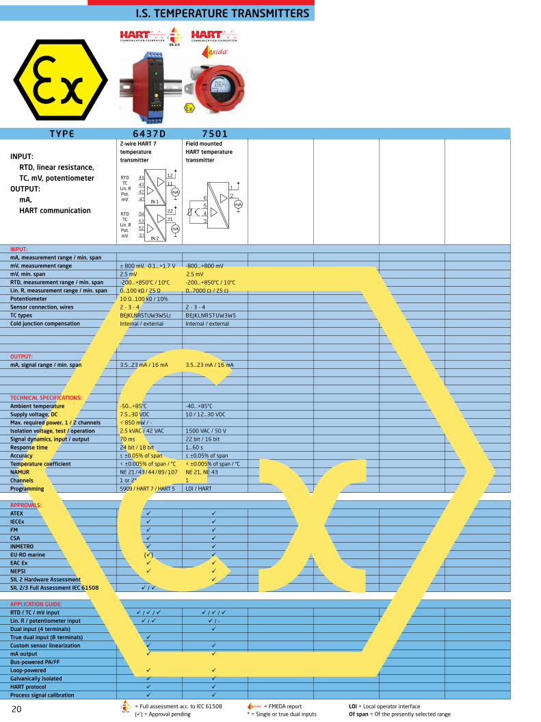
6437D2-wire HART 7 temperature transmitter
± 800 mV, -0.1...+1.7 V
2.5 mV
-200...+850°C / 10°C
0...100 kΩ / 25 Ω
10 Ω...100 kΩ / 10%
2 - 3 - 4
BEJKLNRSTUW3W5Lr
Internal / external
3.5...23 mA / 16 mA
-50...+85°C
7.5...30 VDC
< 850 mW / -
2.5 kVAC / 42 VAC
70 ms
24 bit / 18 bit
≤ ±0.05% of span
< ±0.005% of span / °C
NE 21 / 43 / 44 / 89 / 107
1 or 2*
5909 / HART 7 / HART 5
TYPE
INPUT: RTD, linear resistance, TC, mV, potentiometer
OUTPUT: mA, HART communication
INPUT:mA, measurement range / min. span mV, measurement range mV, min. spanRTD, measurement range / min. spanLin. R, measurement range / min. spanPotentiometerSensor connection, wiresTC types Cold junction compensation
OUTPUT:mA, signal range / min. span
TECHNICAL SPECIFICATIONS: Ambient temperatureSupply voltage, DCMax. required power, 1 / 2 channelsIsolation voltage, test / operationSignal dynamics, input / outputResponse time AccuracyTemperature coefficientNAMUR ChannelsProgramming
APPROVALS:ATEX IECEx FM CSA INMETRO EU-RO marine EAC Ex NEPSI SIL 2 Hardware Assessment SIL 2/3 Full Assessment IEC 61508
APPLICATION GUIDE:RTD / TC / mV input Lin. R / potentiometer inputDual input (4 terminals) True dual input (8 terminals)Custom sensor linearization mA outputBus-powered PA/FFLoop-poweredGalvanically isolatedHART protocolProcess signal calibration
I.S. TEMPERATURE TRANSMITTERS
= Full assessment acc. to IEC 61508 = FMEDA report LOI = Local operator interface () = Approval pending * = Single or true dual inputs Of span = Of the presently selected range
7501Field mounted HART temperature transmitter
-800...+800 mV
2.5 mV
-200...+850°C / 10°C
0...7000 Ω / 25 Ω
2 - 3 - 4
BEJKLNRSTUW3W5
Internal / external
3.5...23 mA / 16 mA
-40...+85°C
10 / 12...30 VDC
1500 VAC / 50 V
22 bit / 16 bit
1...60 s
≤ ±0.05% of span
< ±0.005% of span / °C
NE 21, NE 43
1
LOI / HART
21
mATx
mATx
C O M M U N I C AT I O N F O U N D AT I O N C O M M U N I C AT I O N F O U N D AT I O N
/ / - / - / - / - / -
/ - / - / - / - / - / / /
/ - / - / - / - / - / - / - / - / - / / / - / /
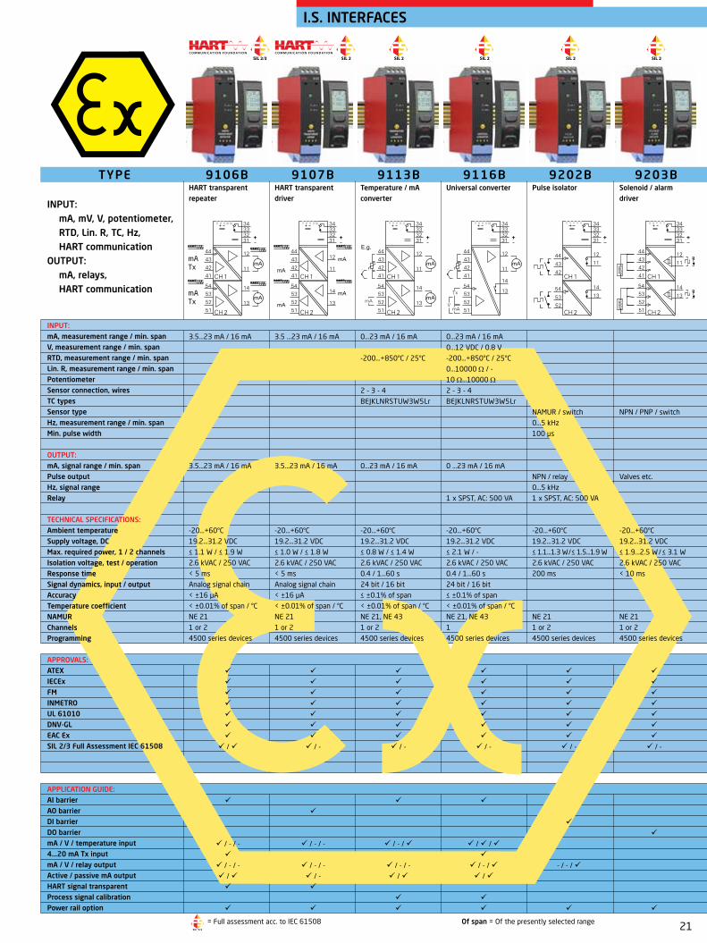
I.S. INTERFACES
TYPE
INPUT: mA, mV, V, potentiometer, RTD, Lin. R, TC, Hz, HART communication
OUTPUT: mA, relays, HART communication
INPUT: mA, measurement range / min. spanV, measurement range / min. spanRTD, measurement range / min. span Lin. R, measurement range / min. span PotentiometerSensor connection, wires TC typesSensor typeHz, measurement range / min. spanMin. pulse width
OUTPUT:mA, signal range / min. spanPulse outputHz, signal rangeRelay
TECHNICAL SPECIFICATIONS: Ambient temperatureSupply voltage, DCMax. required power, 1 / 2 channelsIsolation voltage, test / operationResponse time Signal dynamics, input / output AccuracyTemperature coefficientNAMURChannels Programming
APPROVALS:ATEX IECEx FM INMETRO UL 61010 DNV-GL EAC Ex SIL 2/3 Full Assessment IEC 61508
APPLICATION GUIDE:AI barrierAO barrierDI barrierDO barriermA / V / temperature input4...20 mA Tx inputmA / V / relay outputActive / passive mA outputHART signal transparentProcess signal calibrationPower rail option
9106BHART transparent repeater
3.5...23 mA / 16 mA
3.5...23 mA / 16 mA
-20...+60°C
19.2...31.2 VDC
≤ 1.1 W / ≤ 1.9 W
2.6 kVAC / 250 VAC
< 5 ms
Analog signal chain
< ±16 µA
< ±0.01% of span / °C
NE 21
1 or 2
4500 series devices
9202BPulse isolator
NAMUR / switch
0...5 kHz
100 µs
NPN / relay
0...5 kHz
1 x SPST, AC: 500 VA
-20...+60°C
19.2...31.2 VDC
≤ 1.1...1.3 W / ≤ 1.5...1.9 W
2.6 kVAC / 250 VAC
200 ms
NE 21
1 or 2
4500 series devices
9116BUniversal converter
0...23 mA / 16 mA
0...12 VDC / 0.8 V
-200...+850°C / 25°C
0...10000 Ω / - 10 Ω...10000 Ω
2 - 3 - 4
BEJKLNRSTUW3W5Lr
0 ...23 mA / 16 mA
1 x SPST, AC: 500 VA
-20...+60°C
19.2...31.2 VDC
≤ 2.1 W / -
2.6 kVAC / 250 VAC
0.4 / 1...60 s
24 bit / 16 bit
≤ ±0.1% of span
< ±0.01% of span / °C
NE 21, NE 43
1
4500 series devices
9107BHART transparent driver
3.5 ...23 mA / 16 mA
3.5...23 mA / 16 mA
-20...+60°C
19.2...31.2 VDC
≤ 1.0 W / ≤ 1.8 W
2.6 kVAC / 250 VAC
< 5 ms
Analog signal chain
< ±16 µA
< ±0.01% of span / °C
NE 21
1 or 2
4500 series devices
9113BTemperature / mA converter
0...23 mA / 16 mA
-200...+850°C / 25°C
2 - 3 - 4
BEJKLNRSTUW3W5Lr
0...23 mA / 16 mA
-20...+60°C
19.2...31.2 VDC
≤ 0.8 W / ≤ 1.4 W
2.6 kVAC / 250 VAC
0.4 / 1...60 s
24 bit / 16 bit
≤ ±0.1% of span
< ±0.01% of span / °C
NE 21, NE 43
1 or 2
4500 series devices
9203BSolenoid / alarm driver
NPN / PNP / switch
Valves etc.
-20...+60°C
19.2...31.2 VDC
≤ 1.9...2.5 W / ≤ 3.1 W
2.6 kVAC / 250 VAC
< 10 ms
NE 21
1 or 2
4500 series devices
= Full assessment acc. to IEC 61508 Of span = Of the presently selected range

22
C O M M U N I C AT I O N F O U N D AT I O N C O M M U N I C AT I O N F O U N D AT I O N
/ / / / - / / - / - / - / - / - / / / /
/ / / / - / / - / - / - / - / - / / - / / -
/ / - / / - / /
Of span = Of the presently selected range
5105BEx-isolated driver
0...23 mA / 16 mA
0...10 VDC / 8 VDC
20% of selec. max. value
0...23 mA / 16 mA
≤ 770 Ω
0...10 VDC / 0.8 VDC
20% of selec. max. value
-20...+60°C
21.6...253 V / 19.2...300 V
1.3 W / 2.0 W
3.75 kVAC / 250 VAC
< 25 ms
Analog signal chain
≤ ±0.1% of span
< ±0.01% of span / °C
NE 21
1 or 2
DIP Switch
TYPE
INPUT: mA, mV, V, potentiometer, RTD, linear resistance, TC, HART communication
OUTPUT: mA, V, relays, HART communication
INPUT: mA, measurement range / min. span V, measurement range / min. span mV, measurement range / min. span RTD, measurement range / min. span Lin. R, measurement range / min. span PotentiometerSensor connection, wires TC types Max. offset
OUTPUT: mA, signal range / min. spanLoad (@ current output) V, signal range / min. spanMax. offset
TECHNICAL SPECIFICATIONS: Ambient temperature Supply voltage, AC / DC Max. required power, 1 / 2 channels Isolation voltage, test / operation Response time Signal dynamics, input / output Accuracy Temperature coefficient NAMUR Channels Programming
APPROVALS:ATEX IECEx FM CSA UL DNV-GL EAC Ex
APPLICATION GUIDE:AI barrierAO barrierDI barrierDO barrierRTD / TC input mA / V / mV input4...20 mA Tx input Lin. R / potentiometer inputmA / V / relay outputActive / passive mA outputProcess signal calibration
5104BEx repeater / power supply
0...23 mA / 16 mA
0...10 VDC / 8 VDC
20% of selec. max. value
0...23 mA / 16 mA
≤ 600 Ω
0...10 VDC / 0.8 VDC
20% of selec. max. value
-20...+60°C
21.6...253 V / 19.2...300 V
2.0 W / 2.8 W
3.75 kVAC / 250 VAC
< 25 ms
Analog signal chain
≤ ±0.1% of span
< ±0.01% of span / °C
NE 21
1 or 2
DIP switch
5114BProgrammable transmitter
0...100 mA / 4 mA
0...250 VDC / 5 mV
-150...+150 mV / 5 mV
-200...+850°C / 25°C
0...5000 Ω / 30 Ω
200 Ω...100 kΩ
2 - 3 - 4
BEJKLNRSTUW3W5Lr
50% of selec. max. value
0...23 mA / 10 mA
600 Ω
0...10 VDC / 0.5 VDC
50% of selec. max. value
-20...+60°C
21.6...253 V / 19.2...300 V
2.1 W / 2.8 W
3.75 kVAC / 250 VAC
250 ms...60 s
22 bit / 16 bit
≤ ±0.05% of span
< ±0.01% of span / °C
NE 21, NE 43
1 or 2
5909 + DIP switch
5107BHART transparent driver
3.5...23 mA / 16 mA
20% of selec. max. value
3.5...23 mA / 16 mA
≤ 770 Ω
20% of selec. max. value
-20...+60°C
21.6...253 V / 19.2...300 V
1.4 W / 2.1 W
3.75 kVAC / 250 VAC
< 25 ms
Analog signal chain
≤ ±0.1% of span
< ±0.01% of span / °C
NE 21
1 or 2
No
5115BSignal calculator
0...100 mA / 4 mA
0...250 VDC / 5 mV
-150...+150 mV / 5 mV
-200...+850°C / 25°C
0...5000 Ω / 30 Ω
200 Ω...100 kΩ
2 - 3 - 4
BEJKLNRSTUW3W5Lr
50% of selec. max. val.
0...23 mA / 10 mA
600 Ω
0...10 VDC / 0.5 VDC
50% of selec. max. val.
-20...+60°C
21.6...253 V/19.2...300 V
2.1 W / 2.8 W
3.75 kVAC / 250 VAC
250 ms...60 s
22 bit / 16 bit
≤ ±0.05% of span
< ±0.01% of span / °C
NE 21, NE 43
2
5909 + DIP switch
5106BHART transparent repeater
3.5...23 mA / 16 mA
20% of selec. max. value
3.5...23 mA / 16 mA
≤ 600 Ω
20% of selec. max. value
-20...+60°C
21.6...253 V / 19.2...300 V
2.0 W / 2.8 W
3.75 kVAC / 250 VAC
< 25 ms
Analog signal chain
≤ ±0.1% of span
< ±0.01% of span / °C
NE 21
1 or 2
No
I.S. INTERFACES

23
R
R
/ - / -
/ - /
TYPE INPUT:
mA, mV, V, potentiometer, RTD, linear resistance, TC, Hz
OUTPUT: mA, V, relays
INPUT: mA, measurement range / min. span V, measurement range / min. span mV, measurement range / min. span RTD, measurement range / min. span Lin. R, measurement range / min. spanPotentiometer Sensor connection, wires TC types Sensor type Hz, measurement range / min. spanOUTPUT: mA, signal range / min. span Pulse output Hz, signal range Relays Voltage / current
TECHNICAL SPECIFICATIONS: Ambient temperature Supply voltage, AC / DCMax. required power, 1 / 2 channels Isolation voltage, test / operation Response time Signal dynamics, input / output Accuracy Temperature coefficient NAMUR Channels Programming
APPROVALS:ATEX IECEx FM CSA UL DNV-GL EAC Ex SIL 2, Hardware Assessment
APPLICATION GUIDE:AI barrierAO barrierDI barrierDO barriermA / V / temperature input4...20 mA Tx inputmA / V / relay outputActive / passive mA outputProcess signal calibration
I.S. INTERFACES
5420BEx power supply for 2-wire Tx
1 x SPDT, AC: 100 VA
> 18 VDC / 20 mA
-20...+60°C
21.6...253 V / 19.2...300 V
- / 2.5 W
3.75 kVAC / 250 VAC
NE 21
2
No
5116BProgrammable transmitter
0...100 mA / 4 mA
0...250 VDC / 5 mV
-2500...+2500 mV / 5 mV
-200...+850°C / 25°C
0...5000 Ω / 30 Ω
200 Ω...100 kΩ
2 - 3 - 4
BEJKLNRSTUW3W5Lr
0...23 mA / 10 mA
2 x SPST, AC: 500 VA
-20...+60°C
21.6...253 V / 19.2...300 V
2.4 W / -
3.75 kVAC / 250 VAC
250 ms...60 s
22 bit / 16 bit
≤ ±0.05% of span
< ±0.01% of span / °C
NE 21, NE 43
1
5909
5131B2-wire programmable transmitter
0...100 mA / 4 mA
0...250 VDC / 5 mV
-150...+150 mV / 5 mV
-200...+850°C / 25°C
2 - 3 - 4
BEJKLNRSTUW3W5Lr
3.5...23 mA / 10 mA
-20...+60°C
- / 7.5...35 VDC
0.8 W / 1.6 W
3.75 kVAC / 250 VAC
250 ms...60 s
22 bit / 16 bit
≤ ±0.05% of span
< ±0.01% of span / °C
NE 21, NE 43
1 or 2
5909 + DIP switch
5203BEx solenoid / alarm driver
NPN / PNP / switch
Valves etc.
-20...+60°C
21.6...253 V / 19.2...300 V
2.0 W / 2.5 W
3.75 kVAC / 250 VAC
NE 21
1 or 2
DIP switch
5202BPulse isolator
NAMUR / switch
0...5 kHz
NPN / relay
0...5 kHz
2 x SPDT, AC: 100 VA
-20...+60°C
21.6...253 V / 19.2...300 V
- / 1.8 W
3.75 kVAC / 250 VAC
NE 21
2
DIP switch
5223BProgrammable f/I - f/f converter
NAMUR / switch
0...20 kHz / 0.001 Hz
0...23 mA / 5 mA
NPN / PNP / relay
0...1000 Hz
2 x SPST, AC: 100 VA
-20...+60°C
21.6...253 V / 19.2...300 V
3 W / -
3.75 kVAC / 250 VAC
60 ms...1000 s
- / 16 bit
< ±0.01% of span / °C
1
5909 + DIP switch
= FMEDA report Of span = Of the presently selected range
24
1211
232221
3231
262524
mA
43
4241
/ /
/ - / - / - / - / / - / / -
/ /
/ - - / / -
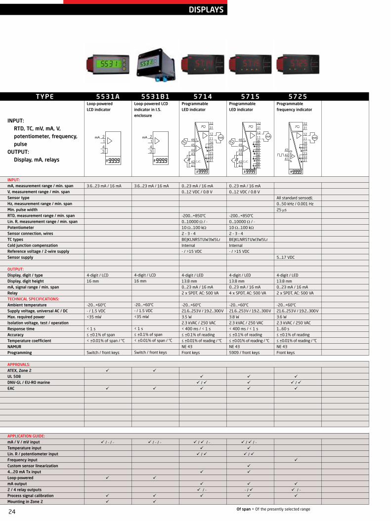
DISPLAYS
Of span = Of the presently selected range
TYPE
INPUT: RTD, TC, mV, mA, V, potentiometer, frequency, pulse
OUTPUT: Display, mA, relays
INPUT:mA, measurement range / min. spanV, measurement range / min. spanSensor typeHz, measurement range / min. spanMin. pulse width RTD, measurement range / min. spanLin. R, measurement range / min. spanPotentiometerSensor connection, wires TC typesCold junction compensation Reference voltage / 2-wire supply Sensor supply
OUTPUT:Display, digit / typeDisplay, digit heightmA, signal range / min. spanRelayTECHNICAL SPECIFICATIONS:Ambient temperatureSupply voltage, universal AC / DCMax. required powerIsolation voltage, test / operationResponse timeAccuracy Temperature coefficientNAMURProgramming
APPROVALS:ATEX, Zone 2 UL 508 DNV-GL / EU-RO marine EAC
APPLICATION GUIDE:mA / V / mV inputTemperature inputLin. R / potentiometer inputFrequency inputCustom sensor linearization4...20 mA Tx inputLoop-poweredmA output2 / 4 relay outputsProcess signal calibrationMounting in Zone 2
5725Programmable frequency indicator
All standard sensors
0...50 kHz / 0.001 Hz
25 ms
5...17 VDC
4-digit / LED
13.8 mm
0...23 mA / 16 mA
2 x SPDT, AC: 500 VA
-20...+60°C
21.6...253 V / 19.2...300 V
3.6 W
2.3 kVAC / 250 VAC
1...60 s
≤ ±0.1% of reading
≤ ±0.01% of reading / °C
NE 43
Front keys
5531ALoop-powered LCD indicator
3.6...23 mA / 16 mA
4-digit / LCD
16 mm
-20...+60°C
- / 1.5 VDC
<35 mW
< 1 s
≤ ±0.1% of span
< ±0.01% of span / °C
Switch / front keys
5531B1Loop-powered LCD indicator in I.S. enclosure
3.6...23 mA / 16 mA
4-digit / LCD
16 mm
-20...+60°C
- / 1.5 VDC
<35 mW
< 1 s
≤ ±0.1% of span
< ±0.01% of span / °C
Switch / front keys
5714Programmable LED indicator
0...23 mA / 16 mA
0...12 VDC / 0.8 V
-200...+850°C
0...10000 Ω / - 10 Ω...100 kΩ
2 - 3 - 4
BEJKLNRSTUW3W5Lr
Internal
- / >15 VDC
4-digit / LED
13.8 mm
0...23 mA / 16 mA
2 x SPDT, AC: 500 VA
-20...+60°C
21.6...253 V / 19.2...300 V
3.5 W
2.3 kVAC / 250 VAC
< 400 ms / < 1 s
≤ ±0.1% of reading
≤ ±0.01% of reading / °C
NE 43
Front keys
5715Programmable LED indicator
0...23 mA / 16 mA
0...12 VDC / 0.8 V
-200...+850°C
0...10000 Ω / - 10 Ω...100 kΩ
2 - 3 - 4
BEJKLNRSTUW3W5Lr
Internal
- / >15 VDC
4-digit / LED
13.8 mm
0...23 mA / 16 mA
4 x SPDT, AC: 500 VA
-20...+60°C
21.6...253 V / 19.2...300 V
3.8 W
2.3 kVAC / 250 VAC
< 400 ms / < 1 s
≤ ±0.1% of reading
≤ ±0.01% of reading / °C
NE 43
5909 / front keys

25
TYPE
INPUT: mA
OUTPUT: Display
INPUT: mA, measurement range / min. span
OUTPUT: Display, digit / type Display, digit height
TECHNICAL SPECIFICATIONS:Ambient temperatureSupply voltage, universal AC / DCMax. required powerIsolation voltage, test / operationResponse timeAccuracy Temperature coefficientNAMURProgramming
APPROVALS:ATEX DNV-GL EAC Ex
APPLICATION GUIDE:Loop-poweredMounting in Zone 1 / 21Field enclosure
5531B2Loop-powered LCD indicator in I.S. enclosure
3.6...23 mA / 16 mA
4-digit / LCD
16 mm
-20...+60°C
- / 1.5 VDC
<35 mW
< 1 s
≤ ±0.1% of span
< ±0.01% of span / °C
Switch / front keys
5531BLoop-powered LCD indicator
3.6...23 mA / 16 mA
4-digit / LCD
16 mm
-20...+60°C
- / 1.5 VDC
<35 mW
< 1 s
≤ ±0.1% of span
< ±0.01% of span / °C
Switch / front keys
I.S. DISPLAYS
Of span = Of the presently selected range

26
7
8
+
/ - / - - /
TYPE INPUT:
AC, DC voltageOUTPUT:
Stabilized VDC
INPUT: Supply voltage, AC Supply voltage, DC Supply voltage, back-up
OUTPUT:Voltage Current Power, max. Status relay
TECHNICAL SPECIFICATIONS: Ambient temperature Max. required power Isolation, test Short circuit protection Output ripple Channels Programming
APPROVALS:ATEX, Zone 2 IECEx, Zone 2 CSA, Zone 2 - DIV 2 FM, Zone 2 - DIV 2 UL 61010 / 508 DNV-GL EAC INMETRO, Zone 2 SIL 2 Full Assessment IEC 61508
APPLICATION GUIDE:115 / 230 VAC mains supply 24 VDC output60 W power rail connector unit96 W power rail connector unitRedundancy power rail functionCollective status signal monitorInternal fuseMounting in Zone 2 / Div 2
POWER SUPPLIES
3405Power connector unit
16.8...31.2 VDC
16.8...31.2 VDC
-25...+70°C
No
Same as input
1
No
9410Power control unit
21.6...26.4 VDC
21.6...26.4 VDC
21.6...26.4 VDC
4 ADC
96 W
1 x SPDT, AC: 500 VA
-20...+60°C
96 W
2.6 kVAC
Yes
Same as input
1
No
9421Power supply
85...132 VAC or
187...264 VAC
24 VDC
4.8 ADC
115 W
-20...+60°C
< 135 W
4.3 kVAC
Yes
200 mV peak / peak
1
No

27
/ / - / / - - / - /
Of span = Of the presently selected range
2224Valve controller
0...20 mA / 16 mA
-10...+10 VDC / 0.8 VDC
> 1 kΩ
3 x PNP
20% of selec. max. value
- / -10...+10 VDC
3000 mA
Supply-0.5 VDC
3-digit / LED
-20...+60°C
12 or 24 VDC
2.2 W
< 75 ms
12 bit / -
< ±0.01% of span / °C
1 or 2 outputs
Switch / front keys
2231Trip amplifier
0...20 mA / 10 mA
0...250 VDC / 0.5 VDC
0...1 ARMS / 0.5 ARMS
0...250 VRMS / 0.5 VRMS
2 x SPST, AC: 500 VA
3-digit / LED
-20...+60°C
21.6...253 V / 19.2...300 V
19.2...28.8 VDC
1.5 W DC / 2 W, UNI
3.75 kVAC / 250 VAC
250 ms...60 s
16 bit / -
0.1% / 0.1%
0...99.9 s / 0...99.9%
< ±0.01% of span / °C
1 input, 2 relays
Switch / front keys
2261mV transmitter
-40...+100 mV / 10 mV
1 x NPN / 1 x PNP
70% of selec. max. value
5...13 VDC / -
0...20 mA / 5 mA
0...10 VDC / 0.25 VDC
50% of selec. max. value
3-digit / LED
-20...+60°C
19.2...28.8 VDC
2.2 W / max. 7.2 W
60 ms...999 s
17 bit / 16 bit
< ±0.01% of span / °C
1
Switch / front keys
TYPE
INPUT, DC: mA, V, potentiometer, frequency, pulse, joystick, load cell, mV
INPUT, AC: A, V
OUTPUT: mA, V, relays
INPUT:mA, DC measurement range / min. span V, DC measurement range / min. span A, AC measurement range / min. span V, AC measurement range / min. span Potentiometer Digital input Max. offset Excitation / reference voltage
OUTPUT: mA, signal range / min. span V, signal range / min. span Max. offset Relays Display, digit / type
TECHNICAL SPECIFICATIONS: Ambient temperature Supply voltage, universal AC / DC Supply voltage, DC Max. required power Isolation voltage, test / operation Response time Signal dynamics, input / output Setpoint adjustment / repetition Delay / hysteresis Temperature coefficient Channels Programming
APPROVALS:DNV-GL EAC
APPLICATION GUIDE:mA / V / mV inputAC signal inputDigital ON/OFF signal inputController / regulator functionLoad cell applicationsProportional valve applicationsFrequency / pulse applicationsmA / V outputRelay output
SPECIAL PRODUCTS

28
SPECIAL PRODUCTS
2255f/I - f/f converter
All standard sensors
0...20 kHz / 0.001 Hz
25 µs
5...15 VDC
0...20 mA / 5 mA
0...10 VDC / 0.25 VDC
50% of selec. max. value
≤ 600 Ω
NPN
1000 Hz
1 x SPDT, AC: 300 VA
3-digit / LED
-20...+60°C
19.2...28.8 VDC
2.4 W
1.4 kVAC / 150 VAC
60 ms...999 s
- / 16 bit
< ±0.01% of span / °C
1
Switch / front keys
TYPE
INPUT, DC: Frequency, pulse
INPUT, AC: A, V
OUTPUT: mA, V, relays, pulse
INPUT: PV / SPA, AC measurement range / min. span V, AC measurement range / min. span Max. offset Sensor typeHz, measurement range / min. spanMin. pulse width Sensor supplyOUTPUT: mA, signal range / min. span V, signal range / min. span Max. offset Load (@ current output) Pulse outputMax. output frequency Relays Display, digit / type
TECHNICAL SPECIFICATIONS: Ambient temperature Supply voltage, universal AC / DC Supply voltage, DC Max. required power Isolation voltage, test / operation Response time Signal dynamics, input / output Accuracy Temperature coefficient Channels Programming
APPROVALS:EAC
APPLICATION GUIDE:Frequency / pulse applicationsmA / V outputRelay output

29
+
A
PLC +
PLC
Tx
SIGNAL TYPES
A user-friendly and reliable mounting solution betweenthe DCS/PLC/SIS system and isolators/I.S. interfaces
Redundant power supply and status relay
DCS/PLC/SIS connections (redundancy supported)
9000 series I/O modules
HART multiplexer connection
LEDs for visualstatus
Pin access for HART communicator
Piano key for fast and robust module connection
Optional 4511 Remote Operator Interface
Optional 4501 Local Operator Interface
Flip-down cover for improved protection
ENERGYENERGY ENERGY ENERGY
OUTPUTINPUT
BACKPLANE
Passive input Active input Active output Passive output
Supply
Active signal Passive device
PR device PR device PR device PR device
Passive PLC Active PLC

30
File Product Input O utput C ommunication Language O ption 08:30:00
PRetop 5331
D ate: 2014-8-10
943201594
PRelectronics
Analog inputAnalog output
Serial no:
Input type:O utput type: 4 - 20mA
UpscaleSensor error:Pt100 D IN/IEC
0.00 - 50.00 C
3-wire
1.00 sec------
Input range:
C onnection:
C old junction comp:
Response time:
Tag no:
5715
5331...5437
5114...5225
6331...6337
4104...42223114 9113...9203
4590
5909
11 131211 1312
11 1312
CH 2
CH 1
23
23
41 4342 4454
41 4342 4454
41 4342 4454
41 4342 4451
11 131221
23
COM
Loop Link
1 2 3 4
OK
PROGRAMMING UNITS
4501Display / programming front
4511Modbus communication enabler
4512Bluetooth communication enabler
4590ConfigMate
SOFTWARE
PResetPReset is an easy-to-use menu-driven software program for set-up of PR products via a standard PC and a programming interface. PReset gives a high degree of flexibility for each product and when the menus are completed, the data is transmitted to the unit which is then ready for operation.
Loop Link 5909Loop Link 5909 is a USB communications interface for configuration and monitoring of PR electronics’ PC-programmable devices. PR devices available in the configuration program PReset ver. 5.0 or higher, can be programmed by way of Loop Link 5909.

31
ACCESSORIES
276USBViator USB HART modem
5909Loop Link communications interface
5913ExCJC connector for I.S. / Ex devices, channel 2
70072-digit digital potentiometer
7011Dial for 10-turn potentiometer
3400TElectromechanical counter
5910CJC connector, channel 1
7002Spring clip
70083-digit digital potentiometer
70121-turn potentiometer, 1 kΩ
4801Modbus gateway
5910ExCJC connector for I.S. / Ex devices, channel 1
7005Shunt resistor 0.1 Ω
700910-turn potentiometer, 200 Ω
7014Shunt resistor 0.5 Ω
4802Modbus RTU/Profinet Gateway
5913CJC connector, channel 2
7006Shunt resistor 1 Ω
701010-turn potentiometer, 20 kΩ
70151-turn potentiometer, 10 kΩ

32
ACCESSORIES
70161-turn potentiometer, 100 kΩ
7024Code ring and code pin
7031Label sheet with engineering units
7430BPt100 cable sensor, Ø6 x 60 mm
8201RPower wire, supply pin 31+33, right
7020Knob for 1-turn potentiometer
702810-turn potentiometer, 2 kΩ
7400Pt100 temperature sensor
7430CPt100 cable sensor, Ø5 x 20 mm
8202LPower wire, supply pin 31+32, left
7020AKnob for 10-turn potentiometer
7029Shunt resistor 0.2 Ω
7410CPt100 temperature sensor
7440Thermowell for 7400 Pt100 sensor
8202RPower wire, supply pin 31+32, right
702311-pole relay socket
7030Shunt resistor 0.1 Ω for DIN rail mounting
7423Ceramic socket for Pt100 sensor
8201LPower wire, supply pin 31+33, left
8335Splash-proof cover

33
ACCESSORIES
8341Inductive proximity sensor, NAMUR
8421DIN rail fitting
85114511 Y-splitter Modbus cable
8516RJ45 female to female shielded cable adapter
8550-S7501 M20 plug with silicone O-ring for stainless steel enclosure
8342Inductive proximity sensor, NAMUR
8501Field enclosure
8513RJ45 Modbus termination
85173 x RJ45 female shielded Y-splitter
8550-SF7501 M20 plug with FKM O-ring for stainless steel enclosure
8343Inductive proximity sensor, NPN
8509M12 interface cable for 5909 Loop Link
85143 X RJ45 female Y-splitter
85507501 M20 plug with silicone O-ring for alu enclosure
85517501 ½NPT plug for alu enclosure
8344Inductive proximity sensor, NPN
85108 unit 4511 Modbus cable
8515RJ45 female to female cable adapter
8550-F7501 M20 plug with FKM O-ring for alu enclosure
8551-S7501 ½NPT plug for stainless steel enclosure

34
ACCESSORIES
8552Pipe-mounting bracket for 7501
8558Bracket spare part for transmitter only (for 7501)
9404Module stop for rail
8555Display with LOI for 7501
9400_1Power rail 15 mm profile
8556Display without LOI for 7501
9400_2Power rail 7.5 mm profile
8557Bracket spare part for display and transmitter (for 7501)
9402Extra end covers for power rail

35
ACCESSORIES
POWER RAIL
The data sheet specifies the maximum required power at nominal operating values, e.g. 24 V supply voltage, 60°C ambient temperature, 600 Ω load, and 20 mA output current.In typical applications, the devices are not running at worst-case conditions, specifically when many devices are located together. For engineering purposes, 70% (P70%) of maximum required power is often used.
ENVIRONMENTAL SPECIFICATIONS
ENCLOSURE SPECIFICATIONS
PR 2200 series PR 3000 series PR 4000 series PR 5000 series PR 5300 seriesSpecifications range
-20°C to +60°C -25°C to +70°C (3105: 0°C to +70°C)
-20°C to +60°C -20°C to +60°C -40°C to +85°C
Relative humidity < 95% RH (non-cond.) < 95% RH (non-cond.) < 95% RH (non-cond.) < 95% RH (non-cond.) < 95% RH (non-cond.)
Protection degree IP50 IP20 IP20 IP20 IP68 / IP00
PR 5400 series PR 5500 / 5700 series
PR 6300 series PR 7500 series PR 9000 series
Specifications range
-50°C to +85°C -20°C to +60°C -40°C to +85°C -20 / -40°C to +85°C -20°C to +60°C
Relative humidity < 99% RH (non-cond.) < 95% RH (non-cond.) < 95% RH (non-cond.) 0...100% RH (cond.) < 95% RH (non-cond.)
Protection degree IP68 / IP00 IP65 from front (5500)IP65 / Type 4X, UL50E
IP20 IP54 / IP66 / IP68 / type 4X
IP20
Dimensions (mm) Height Width Depth Panel cut-out MaterialPR 2200 series 80.5 35.5 84.5+socket Cycoloy/Noryl
PR 3000 series 113 6.1 115 Cycoloy
PR 4000 / 6000 / 9000 series 109 23.5 104 Cycoloy
PR 5000 series 109 23.5 130 Cycoloy
PR 5300 series 20.2 Ø44 Cycoloy
PR 5400 series 20.2 Ø44 Cycoloy
PR 5500 /5700 series 48 96 120 44.5 x 91.5 Noryl
PR 7500 series 109 145 125.5 Aluminum
3000 power railThe number of 3000 devices that can be powered from different power sources is listed in the table below:
The devices can be stacked vertically or horizontally.
Using a PR converter device as power feed-in 3405 power feed-in 9410 power feed-in
P70% Up to 25 devices Up to 160 devices Up to 250 devices
P100% Up to 18 devices Up to 115 devices Up to 184 devices
9000 power railThe number of 9000 devices that can be powered from the 9400 power sources is listed in the table below:
9410 power feed-in
P70% Up to 150 devices
P100% Up to 120 devices

www.prelectronics.com
Benefit today from PERFORMANCE MADE SMARTER
PR electronics is the leading technology company specialized in making industrial process control safer, more reliable and more efficient. Since 1974, we have been dedicated to perfecting our core competence of innovating high precision technology with low power consumption. This dedication continues to set new standards for products communicating, monitoring and connecting our customers’ process measurement points to their process control systems.
Our innovative, patented technologies are derived from our expansive R&D facilities and from having a great understanding of our customers’ needs and processes. We are guided by principles of simplicity, focus, courage and excellence, enabling some of the world’s greatest companies to achieve PERFORMANCE MADE SMARTER.
101
5EN
-W1
5 (1
91
5)