

Fastrack+K2: Editware Fastrack and Grass Valley, a Belden ...
Sierra Wireless FX30 Hardware User Guide
Important Notice
Due to the nature of wireless communications, transmission and reception of data can never be guaranteed. Data may be delayed, corrupted (i.e., have errors) or be totally lost. Although significant delays or losses of data are rare when wireless devices such as the Sierra Wireless modem are used in a normal manner with a well-constructed network, the Sierra Wireless modem should not be used in situations where failure to transmit or receive data could result in damage of any kind to the user or any other party, including but not limited to personal injury, death, or loss of property. Sierra Wireless accepts no responsibility for damages of any kind resulting from delays or errors in data transmitted or received using the Sierra Wireless modem, or for failure of the Sierra Wireless modem to transmit or receive such data.
Safety and Hazards
Do not operate the Sierra Wireless modem in areas where blasting is in progress, near medical equipment, near life support equipment, or any equipment which may be susceptible to any form of radio interference. In such areas, the Sierra Wireless modem MUST BE POWERED OFF. The Sierra Wireless modem can transmit signals that could interfere with this equipment.
The driver or operator of any vehicle should not operate the Sierra Wireless modem while in control of a vehicle. Doing so will detract from the driver or operator's control and operation of that vehicle. In some states and provinces,
Limitation of Liability
The information in this manual is subject to change without notice and does not represent a commitment on the part of Sierra Wireless. SIERRA WIRELESS AND ITS AFFILIATES SPECIFICALLY DISCLAIM LIABILITY FOR ANY AND ALL DIRECT, INDIRECT, SPECIAL, GENERAL, INCIDENTAL, CONSEQUENTIAL, PUNITIVE OR EXEMPLARY DAMAGES INCLUDING, BUT NOT LIMITED TO, LOSS OF PROFITS OR REVENUE OR ANTICIPATED PROFITS OR REVENUE ARISING OUT OF THE USE OR INABILITY TO USE ANY SIERRA WIRELESS PRODUCT, EVEN IF SIERRA WIRELESS AND/OR ITS AFFILIATES HAS BEEN ADVISED OF THE POSSIBILITY OF SUCH DAMAGES OR THEY ARE FORESEEABLE OR FOR CLAIMS BY ANY THIRD PARTY.
Notwithstanding the foregoing, in no event shall Sierra Wireless and/or its affiliates aggregate liability arising under or in connection with the Sierra Wireless product, regardless of the number of events, occurrences, or claims giving rise to liability, be in excess of the price paid by the purchaser for the Sierra Wireless product.
Patents This product may contain technology developed by or for Sierra Wireless Inc. This product includes technology licensed from QUALCOMM®. This product is manufactured or sold by Sierra Wireless Inc. or its affiliates under one or more patents licensed from InterDigital Group and MMP Portfolio Licensing.
Copyright © 2016 Sierra Wireless. All rights reserved.
Trademarks Sierra Wireless®, AirPrime®, AirLink®, AirVantage®, Legato®, and the Sierra Wireless logo are registered trademarks of Sierra Wireless.
Rev 1 Oct.16 2 41110030
Preface
Windows® and Windows Vista® are registered trademarks of Microsoft Corporation.
Linux® is the registered trademark of Linus Torvalds in the U.S. and other countries.
Macintosh® and Mac OS X® are registered trademarks of Apple Inc., registered in the U.S. and other countries.
QUALCOMM® is a registered trademark of QUALCOMM Incorporated. Used under license.
Other trademarks are the property of their respective owners.
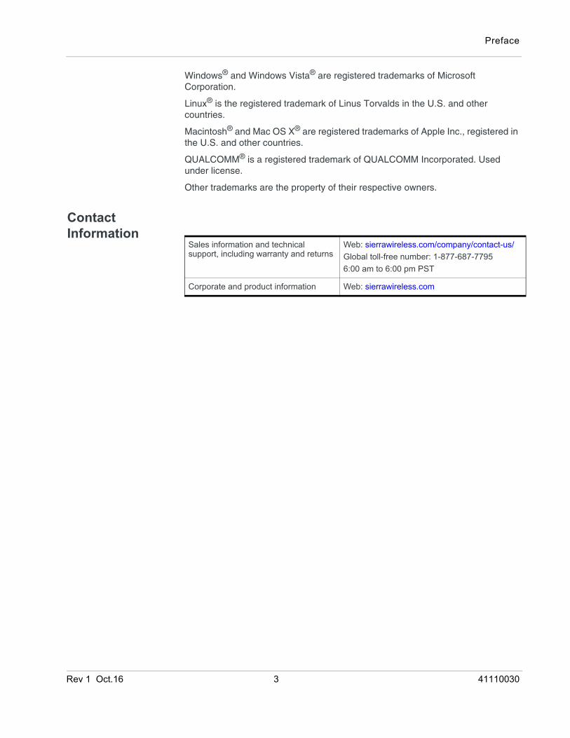
Contact Information
Sales information and technical support, including warranty and returns
Web: sierrawireless.com/company/contact-us/Global toll-free number: 1-877-687-77956:00 am to 6:00 pm PST
Corporate and product information Web: sierrawireless.com
Rev 1 Oct.16 3 41110030
Contents
Introduction to the FX30 . . . . . . . . . . . . . . . . . . . . . . . . . . . . . . . . . . . . . . . . . . .6Key Features . . . . . . . . . . . . . . . . . . . . . . . . . . . . . . . . . . . . . . . . . . . . . . . . . 6
Accessories . . . . . . . . . . . . . . . . . . . . . . . . . . . . . . . . . . . . . . . . . . . . . . . . . . 7
Warranty . . . . . . . . . . . . . . . . . . . . . . . . . . . . . . . . . . . . . . . . . . . . . . . . . . . . . 7
Reference Documents . . . . . . . . . . . . . . . . . . . . . . . . . . . . . . . . . . . . . . . . . . 8
Installation and Startup . . . . . . . . . . . . . . . . . . . . . . . . . . . . . . . . . . . . . . . . . . .9Tools and Materials Required. . . . . . . . . . . . . . . . . . . . . . . . . . . . . . . . . . . . . 9
Installation Overview . . . . . . . . . . . . . . . . . . . . . . . . . . . . . . . . . . . . . . . . . . . 9
Step 1—Insert the SIM Card and Optional IoT Card . . . . . . . . . . . . . . . . . . . 9
Step 2—Mount and Ground the FX30 Chassis . . . . . . . . . . . . . . . . . . . . . . 11Replacing existing Fastrack Supreme or Fastrack Xtend Device . . . . . .13
Step 3—Connect the Antennas . . . . . . . . . . . . . . . . . . . . . . . . . . . . . . . . . . 15
Step 4—Connect the Data Cables. . . . . . . . . . . . . . . . . . . . . . . . . . . . . . . . 16
Cabling Concerns . . . . . . . . . . . . . . . . . . . . . . . . . . . . . . . . . . . . . . . . . . . . . 17Cable Strain Relief . . . . . . . . . . . . . . . . . . . . . . . . . . . . . . . . . . . . . . . . . .17
Step 5—Connect the Power and I/O . . . . . . . . . . . . . . . . . . . . . . . . . . . . . . 17Fusing . . . . . . . . . . . . . . . . . . . . . . . . . . . . . . . . . . . . . . . . . . . . . . . . . . .17Power Connector on the FX30 . . . . . . . . . . . . . . . . . . . . . . . . . . . . . . . . .18Power Modes . . . . . . . . . . . . . . . . . . . . . . . . . . . . . . . . . . . . . . . . . . . . . .18Wiring Diagrams . . . . . . . . . . . . . . . . . . . . . . . . . . . . . . . . . . . . . . . . . . . .19
I/O Configuration . . . . . . . . . . . . . . . . . . . . . . . . . . . . . . . . . . . . . . . . . . . . . 20I/O Pins . . . . . . . . . . . . . . . . . . . . . . . . . . . . . . . . . . . . . . . . . . . . . . . . . .21
Step 6—Check the FX30 operation . . . . . . . . . . . . . . . . . . . . . . . . . . . . . . . 25LED Behavior . . . . . . . . . . . . . . . . . . . . . . . . . . . . . . . . . . . . . . . . . . . . . .26Ethernet LEDs . . . . . . . . . . . . . . . . . . . . . . . . . . . . . . . . . . . . . . . . . . . . .26
Step 7—Using the FX30 . . . . . . . . . . . . . . . . . . . . . . . . . . . . . . . . . . . . . . . 26Using the FX30 as an Embedded Platform for IoT Applications . . . . . . .27AT Commands . . . . . . . . . . . . . . . . . . . . . . . . . . . . . . . . . . . . . . . . . . . . .27Linux Shell Commands . . . . . . . . . . . . . . . . . . . . . . . . . . . . . . . . . . . . . .28Legato Application Framework . . . . . . . . . . . . . . . . . . . . . . . . . . . . . . . . .28
AirVantage IoT Platform . . . . . . . . . . . . . . . . . . . . . . . . . . . . . . . . . . . . . . . . 28
Rev 1 Oct.16 4 41110030
Contents
Specifications . . . . . . . . . . . . . . . . . . . . . . . . . . . . . . . . . . . . . . . . . . . . . . . . . . 30Radio Frequency Bands . . . . . . . . . . . . . . . . . . . . . . . . . . . . . . . . . . . . . . . 33
Radio Module Conducted Transmit Power . . . . . . . . . . . . . . . . . . . . . . . . . 33
Mechanical Specifications . . . . . . . . . . . . . . . . . . . . . . . . . . . . . . . . . . . . . . 35
WP Radio Module Interface Mapping . . . . . . . . . . . . . . . . . . . . . . . . . . . . . 37
Internet of Things (IoT) Expansion Card . . . . . . . . . . . . . . . . . . . . . . . . . . . 39Pin-out Information . . . . . . . . . . . . . . . . . . . . . . . . . . . . . . . . . . . . . . . . . 39
Regulatory Information . . . . . . . . . . . . . . . . . . . . . . . . . . . . . . . . . . . . . . . . . . 40Important Information for North American Users . . . . . . . . . . . . . . . . . . . . . 40
RF Exposure . . . . . . . . . . . . . . . . . . . . . . . . . . . . . . . . . . . . . . . . . . . . . . 40
EU . . . . . . . . . . . . . . . . . . . . . . . . . . . . . . . . . . . . . . . . . . . . . . . . . . . . . . . . 41
Accessories . . . . . . . . . . . . . . . . . . . . . . . . . . . . . . . . . . . . . . . . . . . . . . . . . . . 42DC Power Cable (Black Connector) . . . . . . . . . . . . . . . . . . . . . . . . . . . . . . 42
AC Power Adapter (Black Connector) . . . . . . . . . . . . . . . . . . . . . . . . . . . . . 43AC Power Adapter Input . . . . . . . . . . . . . . . . . . . . . . . . . . . . . . . . . . . . . 43AC Power Adapter Output . . . . . . . . . . . . . . . . . . . . . . . . . . . . . . . . . . . . 43AC Power Adapter Environmental Specifications . . . . . . . . . . . . . . . . . . 43AC Power Adapter Reliability and Quality Control . . . . . . . . . . . . . . . . . . 44AC Power Adapter Safety Standards . . . . . . . . . . . . . . . . . . . . . . . . . . . 44AC Power Adapter EMC Standards . . . . . . . . . . . . . . . . . . . . . . . . . . . . 44AC Power Adapter Hazardous Substances . . . . . . . . . . . . . . . . . . . . . . . 44AC Power Adapter Energy Efficiency . . . . . . . . . . . . . . . . . . . . . . . . . . . 45
Index. . . . . . . . . . . . . . . . . . . . . . . . . . . . . . . . . . . . . . . . . . . . . . . . . . . . . . . . . 46
Rev 1 Oct.16 5 41110030
Rev 1 Nov
1
1: Introduction to the FX30The Sierra Wireless® FX30, a small, rugged, programmable Internet of Things (IoT) gateway, runs the secure Legato® Application Framework, and a long-term support Linux® operating system. You can use the FX30 as a simple USB modem, but its full potential is realized when you use it as an embedded cellular platform for IoT applications. With Ethernet, USB, I/O interfaces, and IoT Expansion cards, the FX30 can connect to many machines and infrastructures. The Linux-based Legato framework enables you to use efficient low-level C programing to write IoT applications for any connected machine.Key Features• Penta-band HSPA+
• Ethernet 10/100 Mbps
• USB 2.0
• mini-SIM slot
• Three configurable I/Os
• Internet of Things (IoT) slot
• GNSS (GPS/Galileo/GLONASS)
• Legato support
• Ultra low power mode
.16 6 41110030
Introduction to the FX30
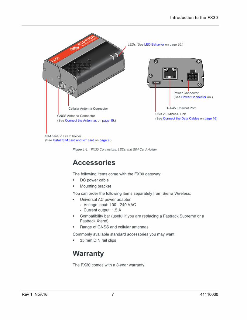
Figure 1-1: FX30 Connectors, LEDs and SIM Card Holder
AccessoriesThe following items come with the FX30 gateway:
• DC power cable
• Mounting bracket
You can order the following items separately from Sierra Wireless:
• Universal AC power adapter· Voltage input: 100– 240 VAC· Current output: 1.5 A
• Compatibility bar (useful if you are replacing a Fastrack Supreme or a Fastrack Xtend)
• Range of GNSS and cellular antennas
Commonly available standard accessories you may want:
• 35 mm DIN rail clips
WarrantyThe FX30 comes with a 3-year warranty.
Power Connector (See Power Connector on.)
SIM card/IoT card holder (See Install SIM card and IoT card on page 9.)
Cellular Antenna Connector USB 2.0 Micro-B Port
(See Connect the Antennas on page 15.) (See Connect the Data Cables on.page 16)
RJ-45 Ethernet Port
GNSS Antenna Connector
LEDs (See LED Behavior on page 26.)
Rev 1 Nov.16 7 41110030
Sierra Wireless FX30 Hardware User Guide
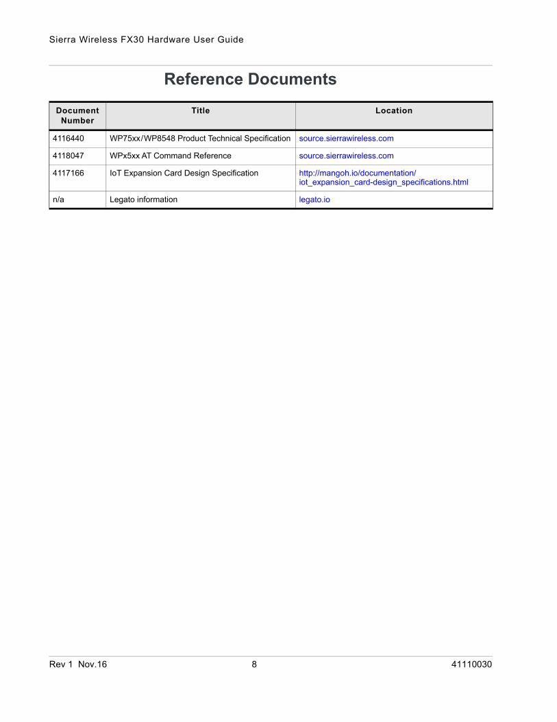
Reference DocumentsDocument
NumberTitle Location
4116440 WP75xx/WP8548 Product Technical Specification source.sierrawireless.com
4118047 WPx5xx AT Command Reference source.sierrawireless.com
4117166 IoT Expansion Card Design Specification http://mangoh.io/documentation/iot_expansion_card-design_specifications.html
n/a Legato information legato.io
Rev 1 Nov.16 8 41110030
Rev 1 Nov
2
2: Installation and StartupThis chapter shows how to connect, install and start the Sierra Wireless FX30. It also describes the front panel LEDs, and I/O functionality.Note: The FX30 must be installed by a qualified technician.
Tools and Materials Required• mini-SIM card (provided by your mobile network operator)
• #1 Phillips screwdriver
• Laptop computer
• AC adapter or DC power cable
• micro-B USB cable
• Cellular antenna
• Optional:· GNSS antenna
Installation OverviewThe steps for a typical installation are:
1. Insert the SIM card and optional IoT Expansion card.
2. Mount and ground the FX30.
3. Connect the antennas.
4. Connect the data cables.
5. Connect the power and I/O.
6. Check the FX30 operation.
7. Using the FX30.
The following sections describe these steps in detail. Read these sections carefully before performing the installation.
Step 1—Insert the SIM Card and Optional IoT CardThe Sierra Wireless FX30 has one mini-SIM (2FF) card slot.
If the SIM card has not already been installed, insert the SIM card into the gateway before connecting any external equipment or power to the FX30.
.16 9 41110030

Sierra Wireless FX30 Hardware User Guide
To install the SIM card:
1. Use a Phillips screwdriver to remove the cover.
2. Orient the SIM card, as shown in Figure 2-1. The gold contacts on the SIM card face up.
3. Gently slide the SIM card into the slot until it clicks into place.
To remove a SIM card, press the SIM card in, and release it. Gently grip the SIM card and pull it out.
Figure 2-1: Installing the SIM Card
4. Replace the cover.
The FX30 has a slot for an Internet of Things (IoT) Expansion Card that provides a standard hardware interface for sensors, network adapters and other IoT technologies. Using Legato, you can design host applications for the IoT Expansion Card. For more information, see Internet of Things (IoT) Expansion Card on page 39.
To install an IoT Expansion card:
1. Use a Phillips screwdriver to remove the SIM card cover.
2. Orient the IoT Expansion card as shown in Figure 2-2 and slide the card into the IoT slot.
3. Replace the cover.
Rev 1 Nov.16 10 41110030

Installation and Startup
Figure 2-2: Installing the IoT Expansion Card
Step 2—Mount and Ground the FX30 ChassisThe FX30 can be flat mounted, or mounted on a DIN rail. There is also a compatibility bar that allows you to use the same mounting holes if you are replacing a Fastrack Supreme or a Fastrack Xtend programmable gateway. See Replacing existing Fastrack Supreme or Fastrack Xtend Device on page 13.
Mount the FX30 where:
• There is easy access for attaching the cables.
• Cables will not be constricted, close to high amperages or exposed to extreme temperatures.
• The front panel LEDs are easily visible.
• There is adequate airflow.
• It is away from direct exposure to the elements, such as sun, rain, dust, etc.
You can mount the FX30:
• On a flat surface (page 11)
• On a DIN Rail (page 12)
To flat mount the FX30:
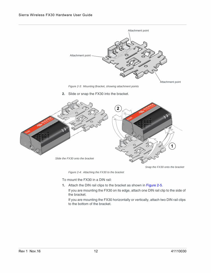
1. Attach the bracket to the mounting surface, using the attachment points shown in Figure 2-3.
Rev 1 Nov.16 11 41110030
Sierra Wireless FX30 Hardware User Guide
Figure 2-3: Mounting Bracket, showing attachment points
2. Slide or snap the FX30 into the bracket.
Figure 2-4: Attaching the FX30 to the bracket
To mount the FX30 in a DIN rail:
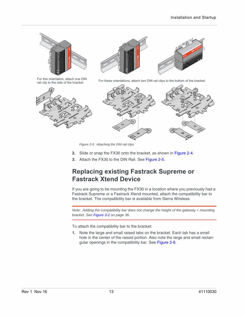
1. Attach the DIN rail clips to the bracket as shown in Figure 2-5.
If you are mounting the FX30 on its edge, attach one DIN rail clip to the side of the bracket.
If you are mounting the FX30 horizontally or vertically, attach two DIN rail clips to the bottom of the bracket.
Attachment point
Attachment point
Attachment point
1
2
Slide the FX30 onto the bracket
Snap the FX30 onto the bracket
Rev 1 Nov.16 12 41110030
Installation and Startup
Figure 2-5: Attaching the DIN rail clips
2. Slide or snap the FX30 onto the bracket, as shown in Figure 2-4.
3. Attach the FX30 to the DIN Rail. See Figure 2-5.
Replacing existing Fastrack Supreme or Fastrack Xtend DeviceIf you are going to be mounting the FX30 in a location where you previously had a Fastrack Supreme or a Fastrack Xtend mounted, attach the compatibility bar to the bracket. The compatibility bar is available from Sierra Wireless.
Note: Adding the compatibility bar does not change the height of the gateway + mounting bracket. See Figure 3-2 on page 36.
To attach the compatibility bar to the bracket:
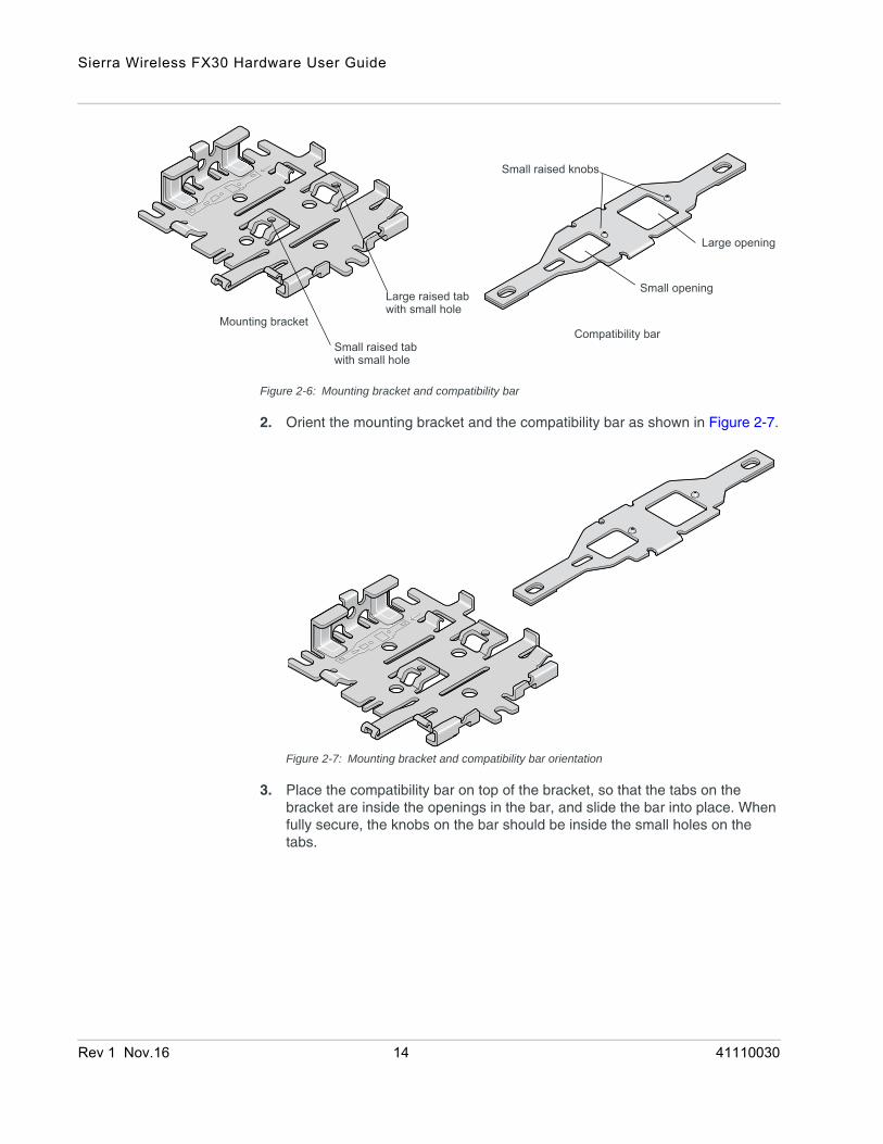
1. Note the large and small raised tabs on the bracket. Each tab has a small hole in the center of the raised portion. Also note the large and small rectan-gular openings in the compatibility bar. See Figure 2-6.
For this orientation, attach one DINrail clip to the side of the bracket. For these orientations, attach two DIN rail clips to the bottom of the bracket.
Rev 1 Nov.16 13 41110030
Sierra Wireless FX30 Hardware User Guide
Figure 2-6: Mounting bracket and compatibility bar
2. Orient the mounting bracket and the compatibility bar as shown in Figure 2-7.
Figure 2-7: Mounting bracket and compatibility bar orientation
3. Place the compatibility bar on top of the bracket, so that the tabs on the bracket are inside the openings in the bar, and slide the bar into place. When fully secure, the knobs on the bar should be inside the small holes on the tabs.
Mounting bracketCompatibility bar
Small raised tab
Small opening
Large opening
Small raised knobs
Large raised tabwith small hole
with small hole
Rev 1 Nov.16 14 41110030
Installation and Startup
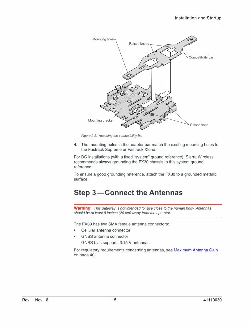
Figure 2-8: Attaching the compatibility bar
4. The mounting holes in the adapter bar match the existing mounting holes for the Fastrack Supreme or Fastrack Xtend.
For DC installations (with a fixed “system” ground reference), Sierra Wireless recommends always grounding the FX30 chassis to this system ground reference.
To ensure a good grounding reference, attach the FX30 to a grounded metallic surface.
Step 3—Connect the Antennas
Warning: This gateway is not intended for use close to the human body. Antennas should be at least 8 inches (20 cm) away from the operator.
The FX30 has two SMA female antenna connectors:
• Cellular antenna connector
• GNSS antenna connector
GNSS bias supports 3.15 V antennas
For regulatory requirements concerning antennas, see Maximum Antenna Gain on page 40.
Raised flapsMounting bracket
Compatibility bar
Raised knobsMounting holes
Rev 1 Nov.16 15 41110030
Sierra Wireless FX30 Hardware User Guide
Note: The antenna should not exceed the maximum gain specified in RF Exposure on page 40. In more complex installations (such as those requiring long lengths of cable and/or multiple connections), you must follow the maximum dBi gain guidelines specified by the radio communications regulations of the Federal Communications Commission (FCC), Industry Canada, or your country’s regulatory body.
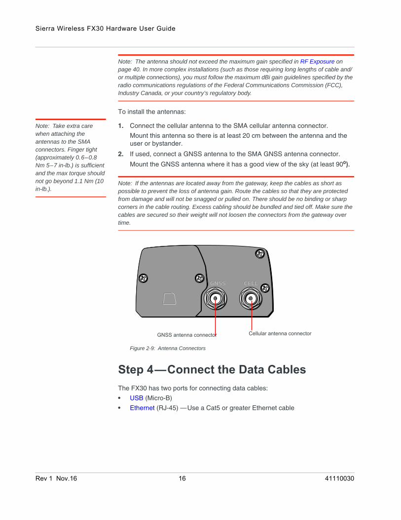
To install the antennas:
Note: Take extra care when attaching the antennas to the SMA connectors. Finger tight (approximately 0.6–0.8 Nm 5–7 in-lb.) is sufficient and the max torque should not go beyond 1.1 Nm (10 in-lb.).
1. Connect the cellular antenna to the SMA cellular antenna connector.
Mount this antenna so there is at least 20 cm between the antenna and the user or bystander.
2. If used, connect a GNSS antenna to the SMA GNSS antenna connector.
Mount the GNSS antenna where it has a good view of the sky (at least 90⁰).
Note: If the antennas are located away from the gateway, keep the cables as short as possible to prevent the loss of antenna gain. Route the cables so that they are protected from damage and will not be snagged or pulled on. There should be no binding or sharp corners in the cable routing. Excess cabling should be bundled and tied off. Make sure the cables are secured so their weight will not loosen the connectors from the gateway over time.
Figure 2-9: Antenna Connectors
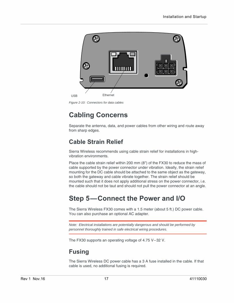
Step 4—Connect the Data CablesThe FX30 has two ports for connecting data cables:
• USB (Micro-B)
• Ethernet (RJ-45) —Use a Cat5 or greater Ethernet cable
Cellular antenna connectorGNSS antenna connector
Rev 1 Nov.16 16 41110030
Installation and Startup
Figure 2-10: Connectors for data cables
Cabling ConcernsSeparate the antenna, data, and power cables from other wiring and route away from sharp edges.
Cable Strain ReliefSierra Wireless recommends using cable strain relief for installations in high-vibration environments.
Place the cable strain relief within 200 mm (8") of the FX30 to reduce the mass of cable supported by the power connector under vibration. Ideally, the strain relief mounting for the DC cable should be attached to the same object as the gateway, so both the gateway and cable vibrate together. The strain relief should be mounted such that it does not apply additional stress on the power connector, i.e. the cable should not be taut and should not pull the power connector at an angle.
Step 5—Connect the Power and I/OThe Sierra Wireless FX30 comes with a 1.5 meter (about 5 ft.) DC power cable. You can also purchase an optional AC adapter.
Note: Electrical installations are potentially dangerous and should be performed by personnel thoroughly trained in safe electrical wiring procedures.
The FX30 supports an operating voltage of 4.75 V–32 V.
FusingThe Sierra Wireless DC power cable has a 3 A fuse installed in the cable. If that cable is used, no additional fusing is required.
USB Ethernet
Rev 1 Nov.16 17 41110030
Sierra Wireless FX30 Hardware User Guide
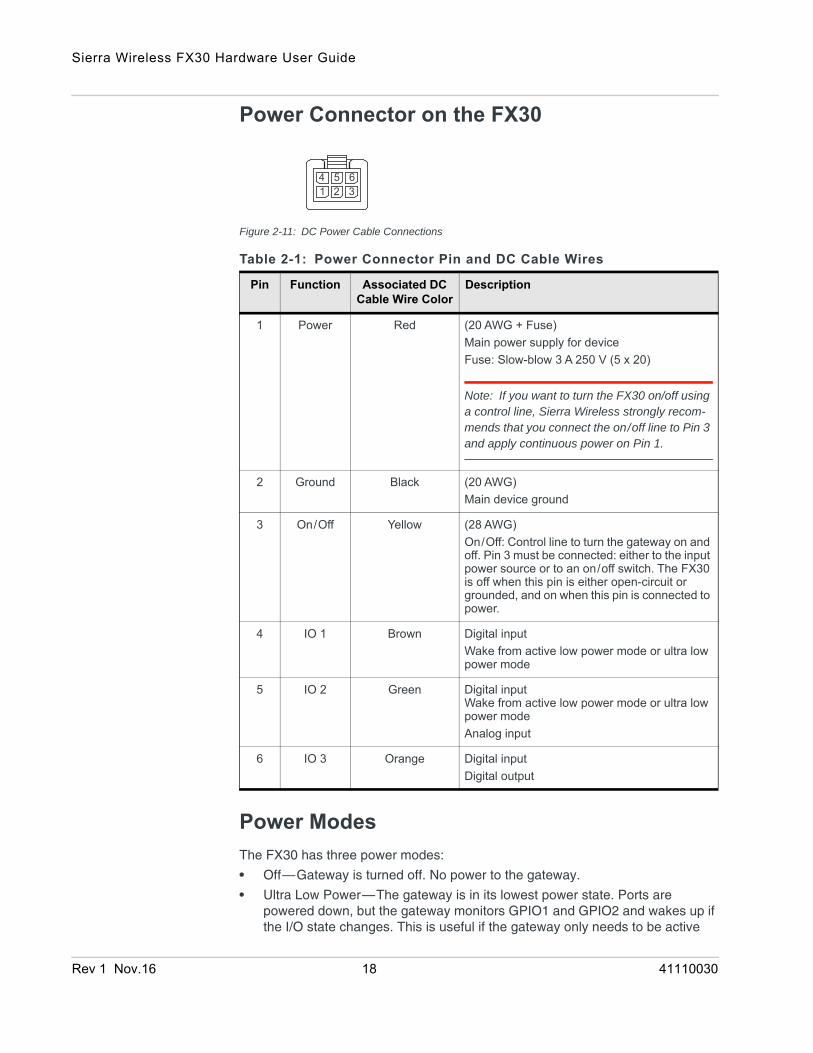
Power Connector on the FX30
Figure 2-11: DC Power Cable Connections
Power ModesThe FX30 has three power modes:
• Off—Gateway is turned off. No power to the gateway.
• Ultra Low Power—The gateway is in its lowest power state. Ports are powered down, but the gateway monitors GPIO1 and GPIO2 and wakes up if the I/O state changes. This is useful if the gateway only needs to be active
Table 2-1: Power Connector Pin and DC Cable Wires
Pin Function Associated DC Cable Wire Color
Description
1 Power Red (20 AWG + Fuse)Main power supply for deviceFuse: Slow-blow 3 A 250 V (5 x 20)
Note: If you want to turn the FX30 on/off using a control line, Sierra Wireless strongly recom-mends that you connect the on/off line to Pin 3 and apply continuous power on Pin 1.
2 Ground Black (20 AWG)Main device ground
3 On/Off Yellow (28 AWG)On/Off: Control line to turn the gateway on and off. Pin 3 must be connected: either to the input power source or to an on/off switch. The FX30 is off when this pin is either open-circuit or grounded, and on when this pin is connected to power.
4 IO 1 Brown Digital input Wake from active low power mode or ultra low power mode
5 IO 2 Green Digital input Wake from active low power mode or ultra low power modeAnalog input
6 IO 3 Orange Digital inputDigital output
1 2 34 5 6
Rev 1 Nov.16 18 41110030
Installation and Startup
very infrequently (for example, in a remote monitoring station that must transmit data once a day)
• Active Low Power—The gateway is fully powered and operating in a low energy state. The gateway monitors GPIO1 and GPIO2 and wakes up if the I/O state changes.
• On—Gateway is fully powered.
Wiring Diagrams
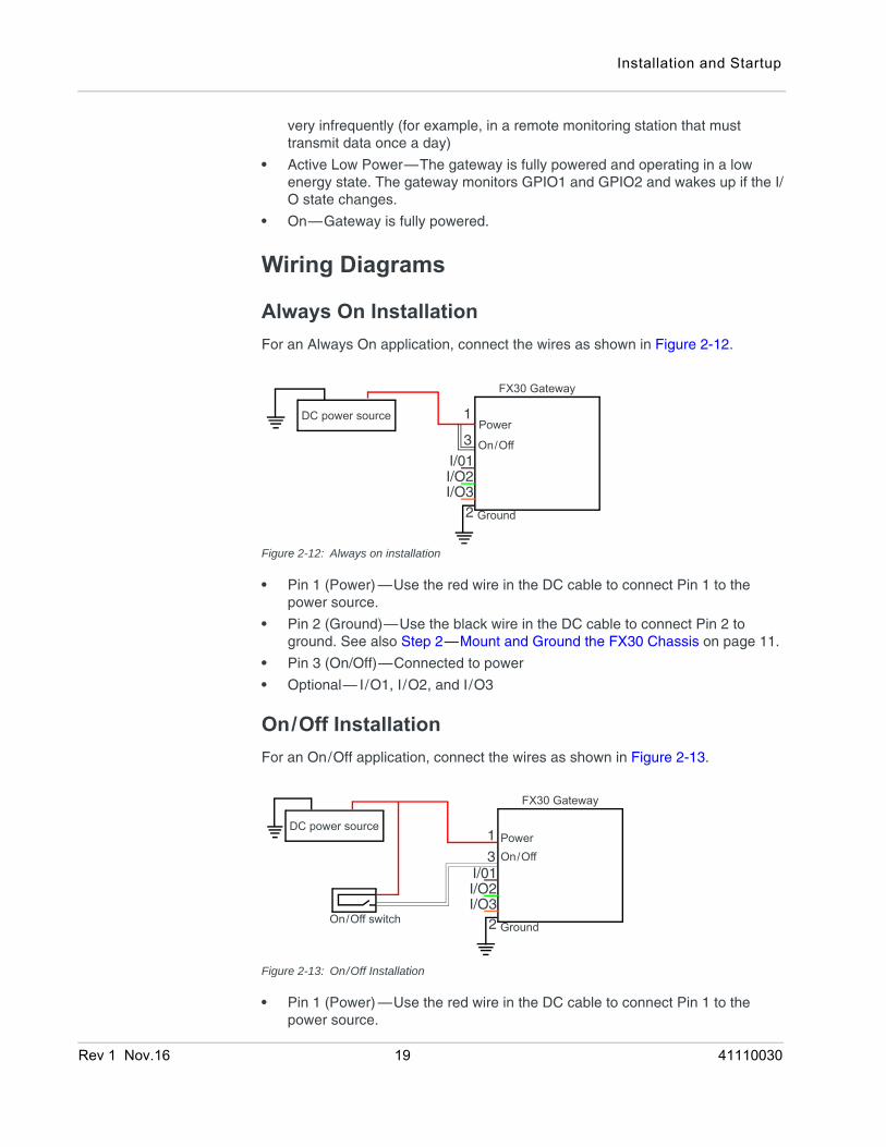
Always On InstallationFor an Always On application, connect the wires as shown in Figure 2-12.
Figure 2-12: Always on installation
• Pin 1 (Power) —Use the red wire in the DC cable to connect Pin 1 to the power source.
• Pin 2 (Ground)—Use the black wire in the DC cable to connect Pin 2 to ground. See also Step 2—Mount and Ground the FX30 Chassis on page 11.
• Pin 3 (On/Off)—Connected to power
• Optional— I/O1, I/O2, and I/O3
On/Off InstallationFor an On/Off application, connect the wires as shown in Figure 2-13.
Figure 2-13: On/Off Installation
• Pin 1 (Power) —Use the red wire in the DC cable to connect Pin 1 to the power source.
FX30 Gateway
Power
On/Off
Ground
DC power source 1
3
2
I/01I/O2I/O3
On/Off switch
DC power source
FX30 Gateway
PowerOn/Off
Ground
1
3
2
I/01I/O2I/O3
Rev 1 Nov.16 19 41110030
Sierra Wireless FX30 Hardware User Guide
• Pin 2 (Ground)—Use the black wire in the DC cable to connect Pin 2 to ground. See also Step 2—Mount and Ground the FX30 Chassis on page 11.
• Pin 3 (On/Off)—Connected to an on/off switch
Pin 3 must be connected.
• Optional— I/O1, I /O2, and I/O3
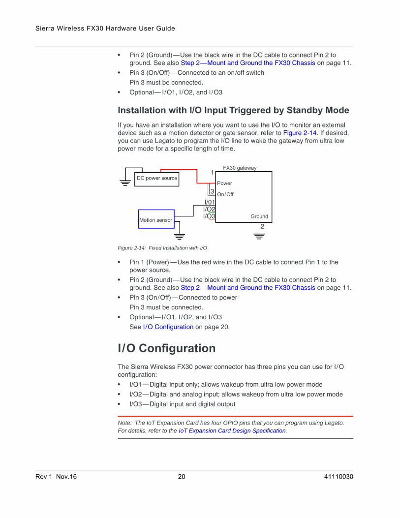
Installation with I/O Input Triggered by Standby ModeIf you have an installation where you want to use the I/O to monitor an external device such as a motion detector or gate sensor, refer to Figure 2-14. If desired, you can use Legato to program the I/O line to wake the gateway from ultra low power mode for a specific length of time.
Figure 2-14: Fixed Installation with I/O
• Pin 1 (Power) —Use the red wire in the DC cable to connect Pin 1 to the power source.
• Pin 2 (Ground)—Use the black wire in the DC cable to connect Pin 2 to ground. See also Step 2—Mount and Ground the FX30 Chassis on page 11.
• Pin 3 (On/Off)—Connected to power
Pin 3 must be connected.
• Optional—I/O1, I/O2, and I/O3
See I/O Configuration on page 20.
I/O ConfigurationThe Sierra Wireless FX30 power connector has three pins you can use for I/O configuration:
• I/O1—Digital input only; allows wakeup from ultra low power mode
• I/O2—Digital and analog input; allows wakeup from ultra low power mode
• I/O3—Digital input and digital output
Note: The IoT Expansion Card has four GPIO pins that you can program using Legato. For details, refer to the IoT Expansion Card Design Specification.
DC power source
FX30 gateway
Power
On/Off
GroundMotion sensor
1
3
2
I/01I/O2I/O3
Rev 1 Nov.16 20 41110030
Installation and Startup
I/O PinsYou can use the I/O pins as:
· Digital inputs(See Table 2-2 on page 22 and Figure 2-15 on page 21.)
· High side pull-ups/dry contact switch inputs (See Figure 2-16 on page 22.)
· Analog inputs (See Table 2-3 on page 23 and Figure 2-17 on page 23.)
· Low side current sinks (See Figure 2-18 on page 24.)
· Digital outputs/open drains (See Table 2-4 on page 25 and Figure 2-19 on page 24.)
Note: The I/O pin functionality is programmable in Legato applications.
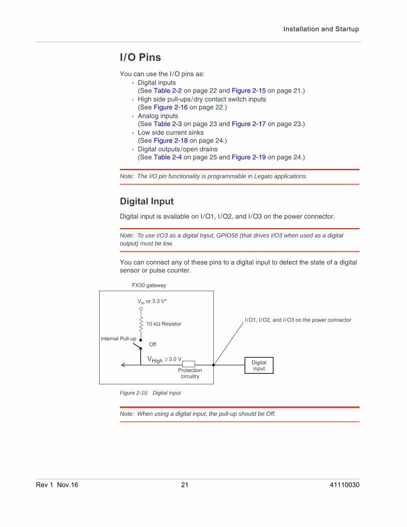
Digital InputDigital input is available on I/O1, I/O2, and I/O3 on the power connector.
Note: To use I/O3 as a digital Input, GPIO56 (that drives I/O3 when used as a digital output) must be low.
You can connect any of these pins to a digital input to detect the state of a digital sensor or pulse counter.
Figure 2-15: Digital Input
Note: When using a digital input, the pull-up should be Off.
FX30 gateway
Off
Vin or 3.3 V*
VHigh ≥ 3.0 V
Protectioncircuitry
Internal Pull-up
10 kΩ Resistor
Digitalinput
I/O1, I/O2, and I/O3 on the power connector
Rev 1 Nov.16 21 41110030
Sierra Wireless FX30 Hardware User Guide
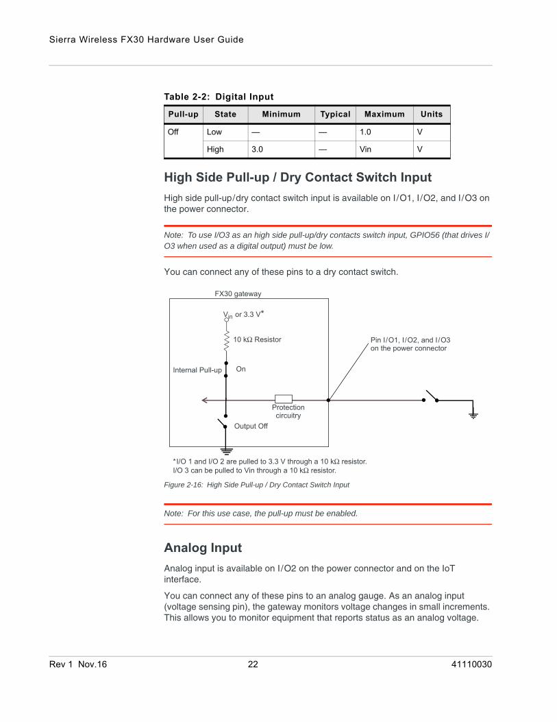
High Side Pull-up / Dry Contact Switch InputHigh side pull-up/dry contact switch input is available on I/O1, I/O2, and I/O3 on the power connector.
Note: To use I/O3 as an high side pull-up/dry contacts switch input, GPIO56 (that drives I/O3 when used as a digital output) must be low.
You can connect any of these pins to a dry contact switch.
Figure 2-16: High Side Pull-up / Dry Contact Switch Input
Note: For this use case, the pull-up must be enabled.
Analog InputAnalog input is available on I/O2 on the power connector and on the IoT interface.
You can connect any of these pins to an analog gauge. As an analog input (voltage sensing pin), the gateway monitors voltage changes in small increments. This allows you to monitor equipment that reports status as an analog voltage.
Table 2-2: Digital Input
Pull-up State Minimum Typical Maximum Units
Off Low — — 1.0 V
High 3.0 — Vin V
FX30 gateway
On
Vin or 3.3 V*
*I/O 1 and I/O 2 are pulled to 3.3 V through a 10 kΩ resistor.
Protectioncircuitry
Internal Pull-up
10 kΩ Resistor
Output Off
Pin I/O1, I/O2, and I/O3
I/O 3 can be pulled to Vin through a 10 kΩ resistor.
on the power connector
Rev 1 Nov.16 22 41110030
Installation and Startup
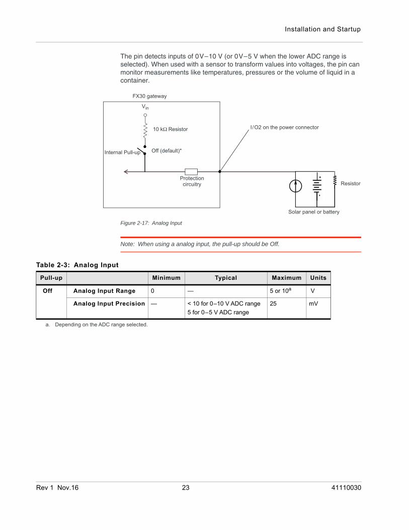
The pin detects inputs of 0V–10 V (or 0V–5 V when the lower ADC range is selected). When used with a sensor to transform values into voltages, the pin can monitor measurements like temperatures, pressures or the volume of liquid in a container.
Figure 2-17: Analog Input
Note: When using a analog input, the pull-up should be Off.
FX30 gateway
Off (default)*
Solar panel or battery
Resistor
Vin
Protectioncircuitry
Internal Pull-up
10 kΩ Resistor I/O2 on the power connector
Table 2-3: Analog Input
Pull-up Minimum Typical Maximum Units
Off Analog Input Range 0 — 5 or 10a V
Analog Input Precision — < 10 for 0–10 V ADC range5 for 0–5 V ADC range
25 mV
a. Depending on the ADC range selected.
Rev 1 Nov.16 23 41110030
Sierra Wireless FX30 Hardware User Guide
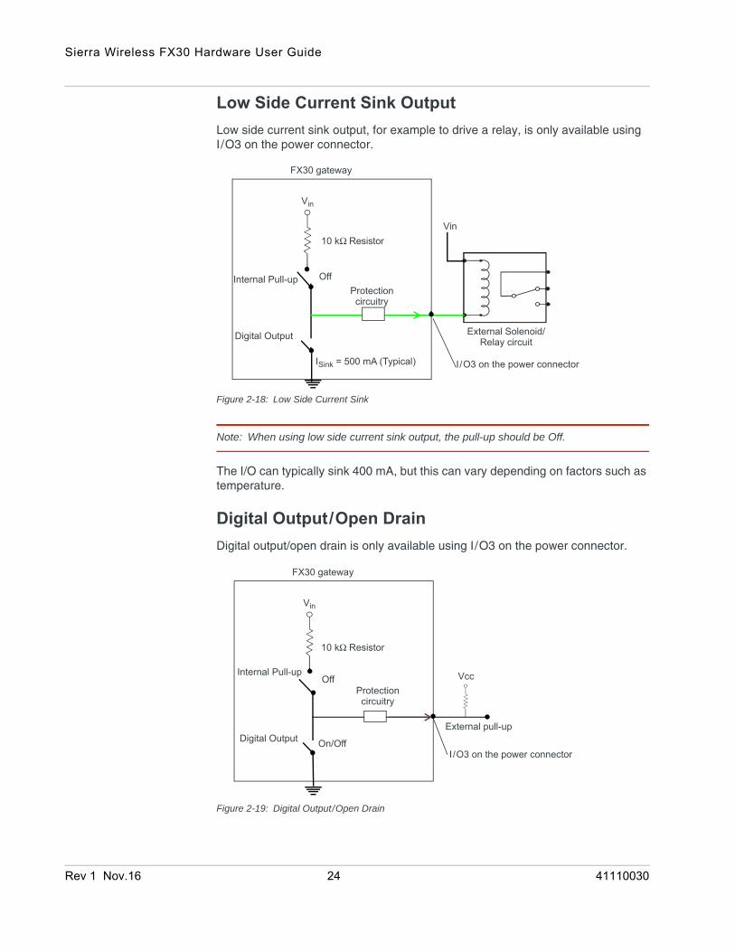
Low Side Current Sink OutputLow side current sink output, for example to drive a relay, is only available using I/O3 on the power connector.
Figure 2-18: Low Side Current Sink
Note: When using low side current sink output, the pull-up should be Off.
The I/O can typically sink 400 mA, but this can vary depending on factors such as temperature.
Digital Output/Open DrainDigital output/open drain is only available using I/O3 on the power connector.
Figure 2-19: Digital Output/Open Drain
FX30 gateway
Off
I/O3 on the power connector
External Solenoid/Relay circuit
Vin
Protectioncircuitry
Vin
ISink = 500 mA (Typical)
Internal Pull-up
10 kΩ Resistor
Digital Output
FX30 gateway
Protectioncircuitry
Vin
External pull-up
On/Off
OffInternal Pull-up
10 kΩ Resistor
Vcc
I/O3 on the power connectorDigital Output
Rev 1 Nov.16 24 41110030
Installation and Startup
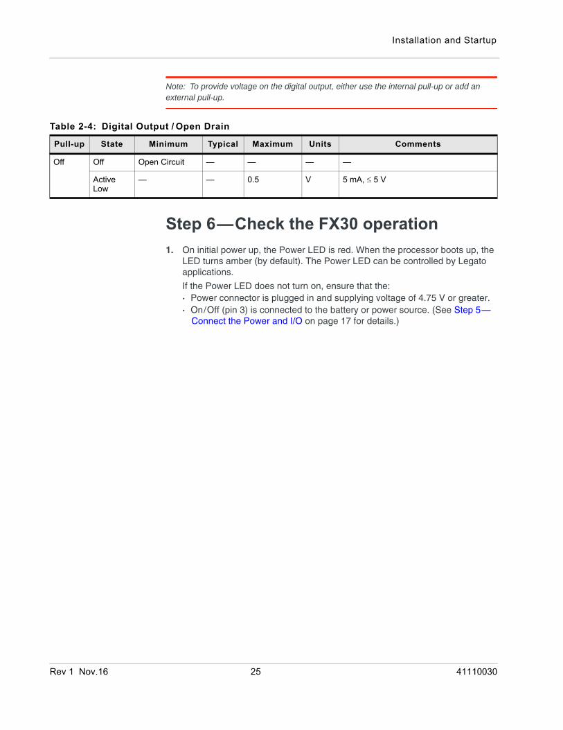
Note: To provide voltage on the digital output, either use the internal pull-up or add an external pull-up.
Step 6—Check the FX30 operation1. On initial power up, the Power LED is red. When the processor boots up, the
LED turns amber (by default). The Power LED can be controlled by Legato applications.
If the Power LED does not turn on, ensure that the:· Power connector is plugged in and supplying voltage of 4.75 V or greater.· On/Off (pin 3) is connected to the battery or power source. (See Step 5—
Connect the Power and I/O on page 17 for details.)
Table 2-4: Digital Output / Open Drain
Pull-up State Minimum Typical Maximum Units Comments
Off Off Open Circuit — — — —
Active Low
— — 0.5 V 5 mA, ≤ 5 V
Rev 1 Nov.16 25 41110030
Sierra Wireless FX30 Hardware User Guide
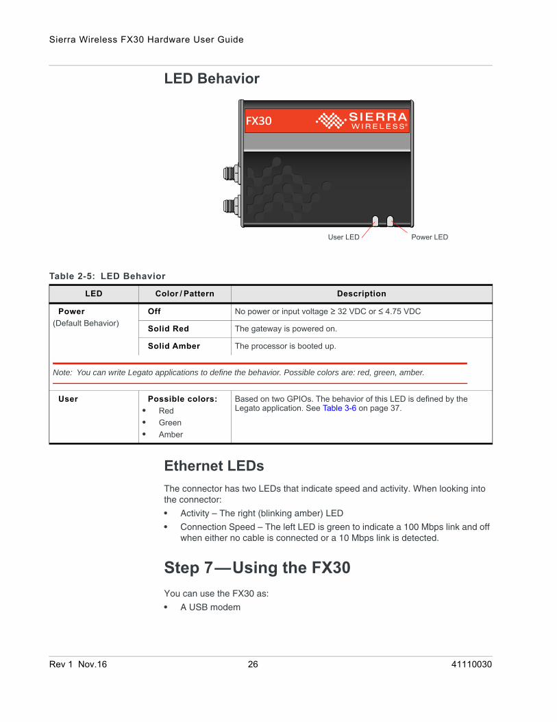
LED Behavior
Ethernet LEDsThe connector has two LEDs that indicate speed and activity. When looking into the connector:
• Activity – The right (blinking amber) LED
• Connection Speed – The left LED is green to indicate a 100 Mbps link and off when either no cable is connected or a 10 Mbps link is detected.
Step 7—Using the FX30You can use the FX30 as:
• A USB modem
Power LEDUser LED
Table 2-5: LED Behavior
LED Color / Pattern Description
Power(Default Behavior)
Off No power or input voltage ≥ 32 VDC or ≤ 4.75 VDC
Solid Red The gateway is powered on.
Solid Amber The processor is booted up.
Note: You can write Legato applications to define the behavior. Possible colors are: red, green, amber.
User Possible colors:• Red• Green• Amber
Based on two GPIOs. The behavior of this LED is defined by the Legato application. See Table 3-6 on page 37.
Rev 1 Nov.16 26 41110030
Installation and Startup
• An embedded cellular platform for IoT applications. The remainder of this section will provide information to get you started and refer you to additional resources.
Using the FX30 as an Embedded Platform for IoT ApplicationsTo program the FX30, you can use:
• AT Commands
• Linux Shell Commands on page 28
• Legato Application Framework on page 28
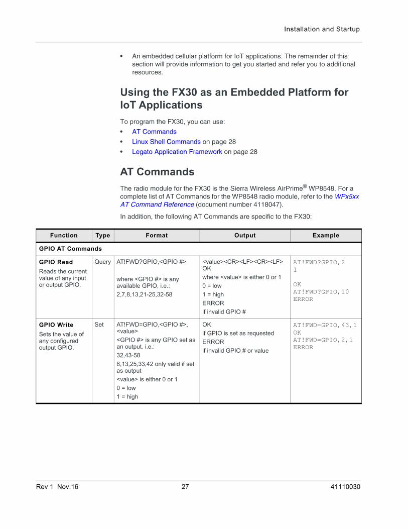
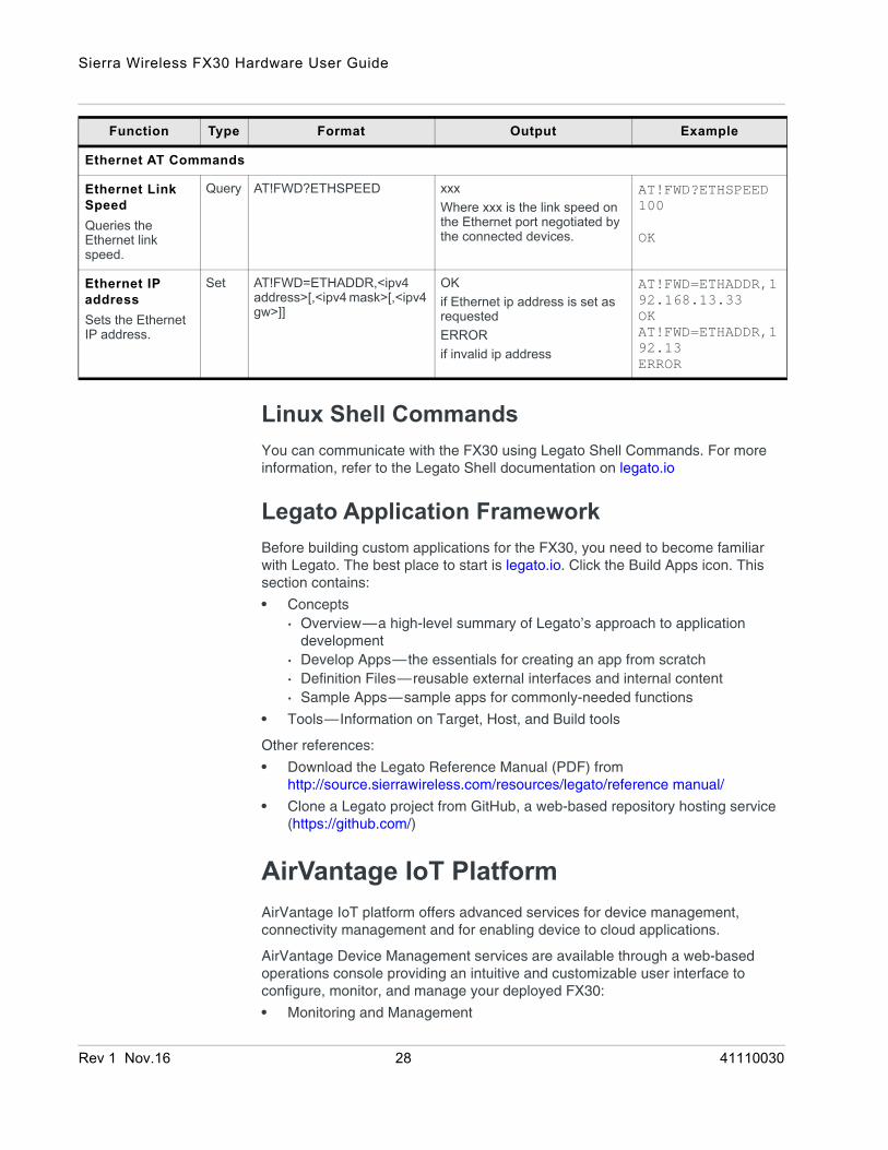
AT CommandsThe radio module for the FX30 is the Sierra Wireless AirPrime® WP8548. For a complete list of AT Commands for the WP8548 radio module, refer to the WPx5xx AT Command Reference (document number 4118047).
In addition, the following AT Commands are specific to the FX30:
Function Type Format Output Example
GPIO AT Commands
GPIO ReadReads the current value of any input or output GPIO.
Query AT!FWD?GPIO,<GPIO #>
where <GPIO #> is any available GPIO, i.e.: 2,7,8,13,21-25,32-58
<value><CR><LF><CR><LF>OKwhere <value> is either 0 or 10 = low1 = highERRORif invalid GPIO #
AT!FWD?GPIO,21
OKAT!FWD?GPIO,10ERROR
GPIO WriteSets the value of any configured output GPIO.
Set AT!FWD=GPIO,<GPIO #>,<value><GPIO #> is any GPIO set as an output. i.e.:32,43-588,13,25,33,42 only valid if set as output<value> is either 0 or 10 = low1 = high
OKif GPIO is set as requestedERRORif invalid GPIO # or value
AT!FWD=GPIO,43,1OKAT!FWD=GPIO,2,1ERROR
Rev 1 Nov.16 27 41110030
Sierra Wireless FX30 Hardware User Guide
Linux Shell CommandsYou can communicate with the FX30 using Legato Shell Commands. For more information, refer to the Legato Shell documentation on legato.io
Legato Application FrameworkBefore building custom applications for the FX30, you need to become familiar with Legato. The best place to start is legato.io. Click the Build Apps icon. This section contains:
• Concepts· Overview—a high-level summary of Legato’s approach to application
development· Develop Apps—the essentials for creating an app from scratch· Definition Files—reusable external interfaces and internal content· Sample Apps—sample apps for commonly-needed functions
• Tools—Information on Target, Host, and Build tools
Other references:
• Download the Legato Reference Manual (PDF) fromhttp://source.sierrawireless.com/resources/legato/reference manual/
• Clone a Legato project from GitHub, a web-based repository hosting service (https://github.com/)
AirVantage IoT PlatformAirVantage IoT platform offers advanced services for device management, connectivity management and for enabling device to cloud applications.
AirVantage Device Management services are available through a web-based operations console providing an intuitive and customizable user interface to configure, monitor, and manage your deployed FX30:
• Monitoring and Management
Ethernet AT Commands
Ethernet Link SpeedQueries the Ethernet link speed.
Query AT!FWD?ETHSPEED xxxWhere xxx is the link speed on the Ethernet port negotiated by the connected devices.
AT!FWD?ETHSPEED100
OK
Ethernet IP addressSets the Ethernet IP address.
Set AT!FWD=ETHADDR,<ipv4 address>[,<ipv4 mask>[,<ipv4 gw>]]
OKif Ethernet ip address is set as requestedERRORif invalid ip address
AT!FWD=ETHADDR,192.168.13.33OKAT!FWD=ETHADDR,192.13ERROR
Function Type Format Output Example
Rev 1 Nov.16 28 41110030

Installation and Startup
• Command and Control
• OTA Firmware Update
• Deployment Configuration
• Legato Application Lifecycle Management
Free and unlimited OTA Firmware Updates are offered with FX30.
To get started either call your Sierra Wireless reseller or visit: https://airvantage.net/
Rev 1 Nov.16 29 41110030
Rev 1 Nov
3
CertificaInterop
EnvironTesting
Electrosta
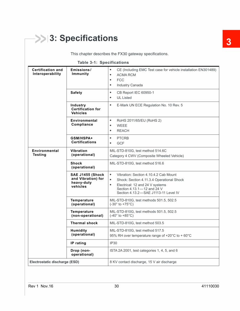
3: SpecificationsThis chapter describes the FX30 gateway specifications.
Table 3-1: Specifications
tion and erability
Emissions /Immunity
• CE (Including EMC Test case for vehicle installation EN301489)• ACMA RCM• FCC• Industry Canada
Safety • CB Report IEC 60950-1• UL Listed
Industry Certification for Vehicles
• E-Mark UN ECE Regulation No. 10 Rev. 5
Environmental Compliance
• RoHS 2011/65/EU (RoHS 2)• WEEE• REACH
GSM/HSPA+ Certifications
• PTCRB• GCF
mental Vibration (operational)
MIL-STD-810G, test method 514.6CCategory 4 CWV (Composite Wheeled Vehicle)
Shock (operational)
MIL-STD-810G, test method 516.6
SAE J1455 (Shock and Vibration) for heavy-duty vehicles
• Vibration: Section 4.10.4.2 Cab Mount• Shock: Section 4.11.3.4 Operational Shock• Electrical: 12 and 24 V systems
Section 4.13.1—12 and 24 VSection 4.13.2—SAE J1113-11 Level IV
Temperature (operational)
MIL-STD-810G, test methods 501.5, 502.5 (-30° to +75°C)
Temperature (non-operational)
MIL-STD-810G, test methods 501.5, 502.5 (-40° to +85°C)
Thermal shock MIL-STD-810G, test method 503.5
Humidity (operational)
MIL-STD-810G, test method 517.595% RH over temperature range of +20°C to + 60°C
IP rating IP30
Drop (non-operational)
ISTA 2A 2001, test categories 1, 4, 5, and 6
tic discharge (ESD) 8 KV contact discharge, 15 V air discharge
.16 30 41110030
Specifications
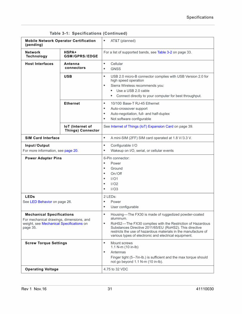
Mobile Network Operator Certification(pending)
• AT&T (planned)
Network Technology
HSPA+GSM /GPRS / EDGE
For a list of supported bands, see Table 3-2 on page 33.
Host Interfaces Antenna connectors
• Cellular• GNSS
USB • USB 2.0 micro-B connector complies with USB Version 2.0 for high speed operation
• Sierra Wireless recommends you:• Use a USB 2.0 cable • Connect directly to your computer for best throughput.
Ethernet • 10/100 Base-T RJ-45 Ethernet• Auto-crossover support• Auto-negotiation, full- and half-duplex• Not software configurable
IoT (Internet of Things) Connector
See Internet of Things (IoT) Expansion Card on page 39.
SIM Card Interface • A mini-SIM (2FF) SIM card operated at 1.8 V/3.3 V.
Input / OutputFor more information, see page 20.
• Configurable I/O• Wakeup on I/O, serial, or cellular events
Power Adapter Pins 6-Pin connector:• Power• Ground• On/Off• I/O1• I/O2• I/O3
LEDsSee LED Behavior on page 26.
2 LEDs:• Power• User configurable
Mechanical SpecificationsFor mechanical drawings, dimensions, and weight, see Mechanical Specifications on page 35.
• Housing—The FX30 is made of ruggedized powder-coated aluminum.
• RoHS2—The FX30 complies with the Restriction of Hazardous Substances Directive 2011/65/EU (RoHS2). This directive restricts the use of hazardous materials in the manufacture of various types of electronic and electrical equipment.
Screw Torque Settings • Mount screws1.1 N-m (10 in-lb)
• AntennasFinger tight (5–7in-lb.) is sufficient and the max torque should not go beyond 1.1 N-m (10 in-lb).
Operating Voltage 4.75 to 32 VDC
Table 3-1: Specifications (Continued)
Rev 1 Nov.16 31 41110030
Sierra Wireless FX30 Hardware User Guide
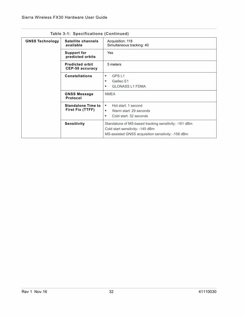
GNSS Technology Satellite channels available
Acquisition: 118Simultaneous tracking: 40
Support for predicted orbits
Yes
Predicted orbit CEP-50 accuracy
5 meters
Constellations • GPS L1• Galileo E1• GLONASS L1 FDMA
GNSS Message Protocol
NMEA
Standalone Time to First Fix (TTFF)
• Hot start: 1 second• Warm start: 29 seconds• Cold start: 32 seconds
Sensitivity Standalone of MS-based tracking sensitivity: -161 dBmCold start sensitivity: -145 dBmMS-assisted GNSS acquisition sensitivity: -158 dBm
Table 3-1: Specifications (Continued)
Rev 1 Nov.16 32 41110030
Specifications
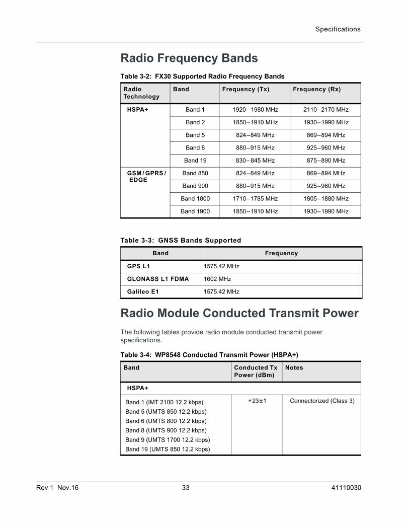
Radio Frequency Bands
Radio Module Conducted Transmit PowerThe following tables provide radio module conducted transmit power specifications.
Table 3-2: FX30 Supported Radio Frequency Bands
Radio Technology
Band Frequency (Tx) Frequency (Rx)
HSPA+ Band 1 1920 –1980 MHz 2110–2170 MHz
Band 2 1850–1910 MHz 1930–1990 MHz
Band 5 824–849 MHz 869–894 MHz
Band 8 880–915 MHz 925–960 MHz
Band 19 830– 845 MHz 875–890 MHz
GSM / GPRS /EDGE
Band 850 824–849 MHz 869–894 MHz
Band 900 880–915 MHz 925–960 MHz
Band 1800 1710–1785 MHz 1805–1880 MHz
Band 1900 1850–1910 MHz 1930–1990 MHz
Table 3-3: GNSS Bands Supported
Band Frequency
GPS L1 1575.42 MHz
GLONASS L1 FDMA 1602 MHz
Galileo E1 1575.42 MHz
Table 3-4: WP8548 Conducted Transmit Power (HSPA+)
Band Conducted Tx Power (dBm)
Notes
HSPA+
Band 1 (IMT 2100 12.2 kbps)Band 5 (UMTS 850 12.2 kbps)Band 6 (UMTS 800 12.2 kbps)Band 8 (UMTS 900 12.2 kbps)Band 9 (UMTS 1700 12.2 kbps)Band 19 (UMTS 850 12.2 kbps)
+23±1 Connectorized (Class 3)
Rev 1 Nov.16 33 41110030
Sierra Wireless FX30 Hardware User Guide
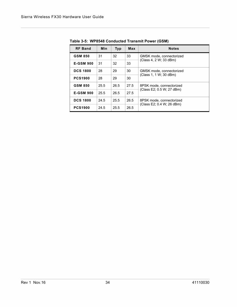
Table 3-5: WP8548 Conducted Transmit Power (GSM)
RF Band Min Typ Max Notes
GSM 850 31 32 33 GMSK mode, connectorized (Class 4, 2 W; 33 dBm)
E-GSM 900 31 32 33
DCS 1800 28 29 30 GMSK mode, connectorized (Class 1, 1 W; 30 dBm)
PCS1900 28 29 30
GSM 850 25.5 26.5 27.5 8PSK mode, connectorized (Class E2; 0.5 W; 27 dBm)
E-GSM 900 25.5 26.5 27.5
DCS 1800 24.5 25.5 26.5 8PSK mode, connectorized (Class E2; 0.4 W; 26 dBm)
PCS1900 24.5 25.5 26.5
Rev 1 Nov.16 34 41110030
Specifications
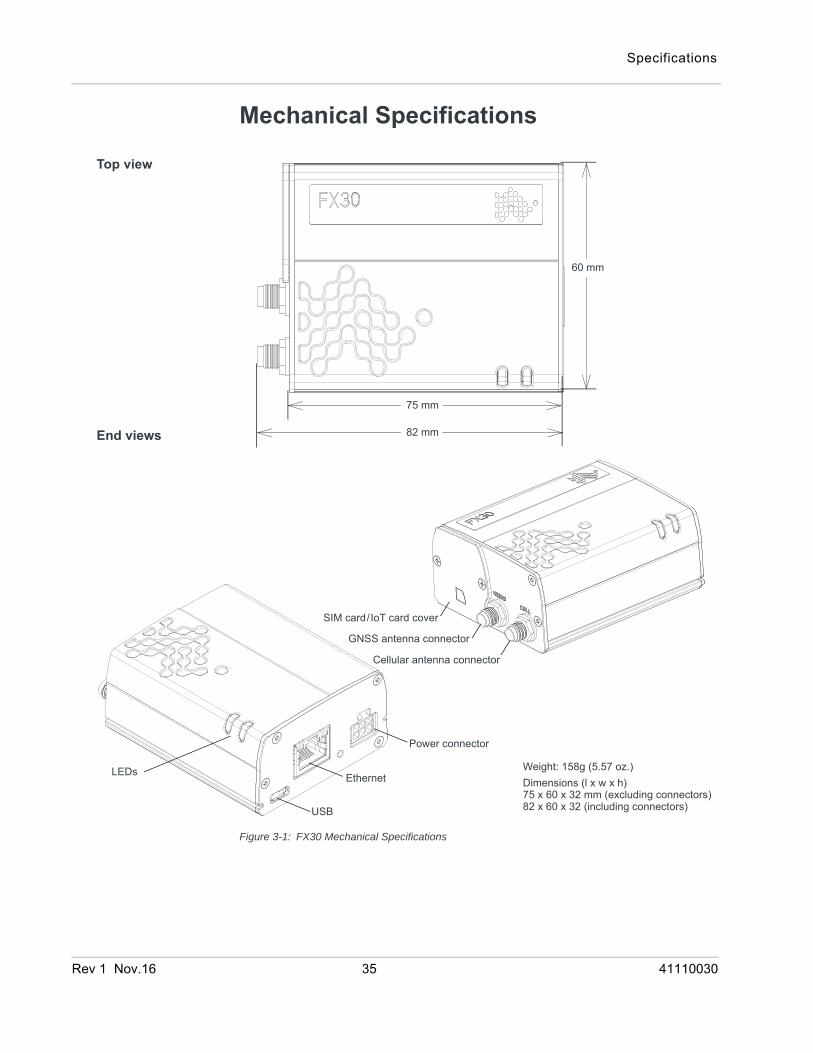
Mechanical Specifications
Figure 3-1: FX30 Mechanical Specifications
Top view
Weight: 158g (5.57 oz.)Dimensions (l x w x h)75 x 60 x 32 mm (excluding connectors)82 x 60 x 32 (including connectors)
82 mm
75 mm
SIM card/IoT card cover
GNSS antenna connector
Cellular antenna connector
USB
Ethernet
Power connector
End views
60 mm
LEDs
Rev 1 Nov.16 35 41110030
Sierra Wireless FX30 Hardware User Guide
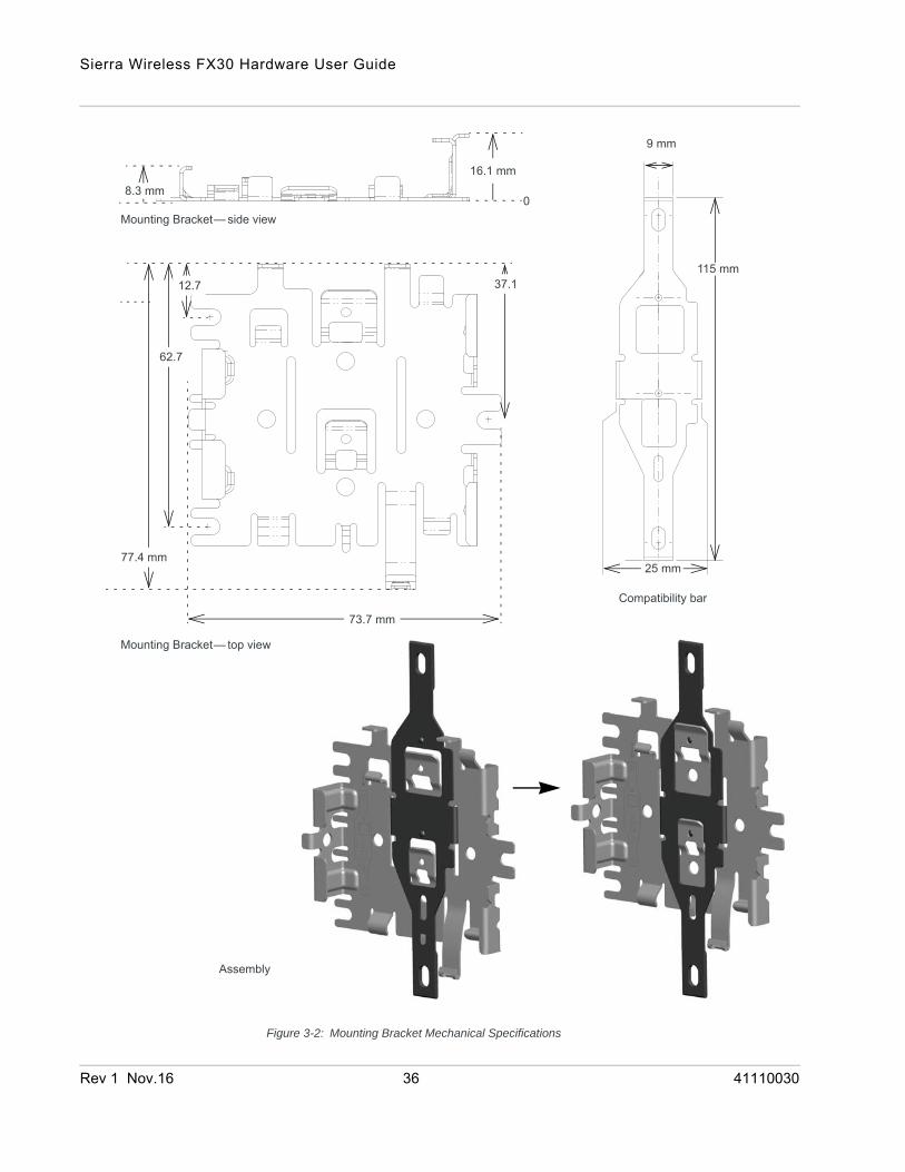
Figure 3-2: Mounting Bracket Mechanical Specifications
77.4 mm
12.7 37.1
62.7
73.7 mm
Mounting Bracket— top view
Mounting Bracket— side view
9 mm
25 mm
115 mm
0
16.1 mm8.3 mm
Assembly
Compatibility bar
Rev 1 Nov.16 36 41110030
Specifications
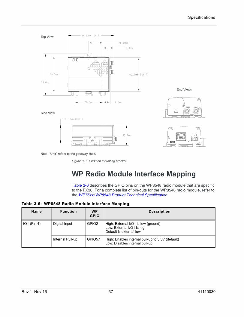
Figure 3-3: FX30 on mounting bracket
WP Radio Module Interface MappingTable 3-6 describes the GPIO pins on the WP8548 radio module that are specific to the FX30. For a complete list of pin-outs for the WP8548 radio module, refer to the WP75xx/WP8548 Product Technical Specification.
Top View
Side View
End Views
Note: “Unit” refers to the gateway itself.
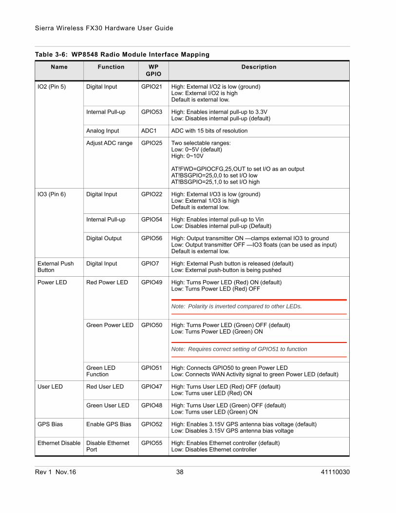
Table 3-6: WP8548 Radio Module Interface Mapping
Name Function WP GPIO
Description
IO1 (Pin 4) Digital Input GPIO2 High: External I/O1 is low (ground)Low: External I/O1 is highDefault is external low.
Internal Pull-up GPIO57 High: Enables internal pull-up to 3.3V (default)Low: Disables internal pull-up
Rev 1 Nov.16 37 41110030
Sierra Wireless FX30 Hardware User Guide
IO2 (Pin 5) Digital Input GPIO21 High: External I/O2 is low (ground)Low: External I/O2 is highDefault is external low.
Internal Pull-up GPIO53 High: Enables internal pull-up to 3.3V Low: Disables internal pull-up (default)
Analog Input ADC1 ADC with 15 bits of resolution
Adjust ADC range GPIO25 Two selectable ranges: Low: 0~5V (default)High: 0~10V
AT!FWD=GPIOCFG,25,OUT to set I/O as an outputAT!BSGPIO=25,0,0 to set I/O lowAT!BSGPIO=25,1,0 to set I/O high
IO3 (Pin 6) Digital Input GPIO22 High: External I/O3 is low (ground)Low: External 1/O3 is highDefault is external low.
Internal Pull-up GPIO54 High: Enables internal pull-up to Vin Low: Disables internal pull-up (Default)
Digital Output GPIO56 High: Output transmitter ON —clamps external IO3 to groundLow: Output transmitter OFF —IO3 floats (can be used as input)Default is external low.
External Push Button
Digital Input GPIO7 High: External Push button is released (default)Low: External push-button is being pushed
Power LED Red Power LED GPIO49 High: Turns Power LED (Red) ON (default)Low: Turns Power LED (Red) OFF
Note: Polarity is inverted compared to other LEDs.
Green Power LED GPIO50 High: Turns Power LED (Green) OFF (default)Low: Turns Power LED (Green) ON
Note: Requires correct setting of GPIO51 to function
Green LED Function
GPIO51 High: Connects GPIO50 to green Power LEDLow: Connects WAN Activity signal to green Power LED (default)
User LED Red User LED GPIO47 High: Turns User LED (Red) OFF (default)Low: Turns user LED (Red) ON
Green User LED GPIO48 High: Turns User LED (Green) OFF (default)Low: Turns user LED (Green) ON
GPS Bias Enable GPS Bias GPIO52 High: Enables 3.15V GPS antenna bias voltage (default)Low: Disables 3.15V GPS antenna bias voltage
Ethernet Disable Disable Ethernet Port
GPIO55 High: Enables Ethernet controller (default)Low: Disables Ethernet controller
Table 3-6: WP8548 Radio Module Interface Mapping
Name Function WP GPIO
Description
Rev 1 Nov.16 38 41110030
Specifications
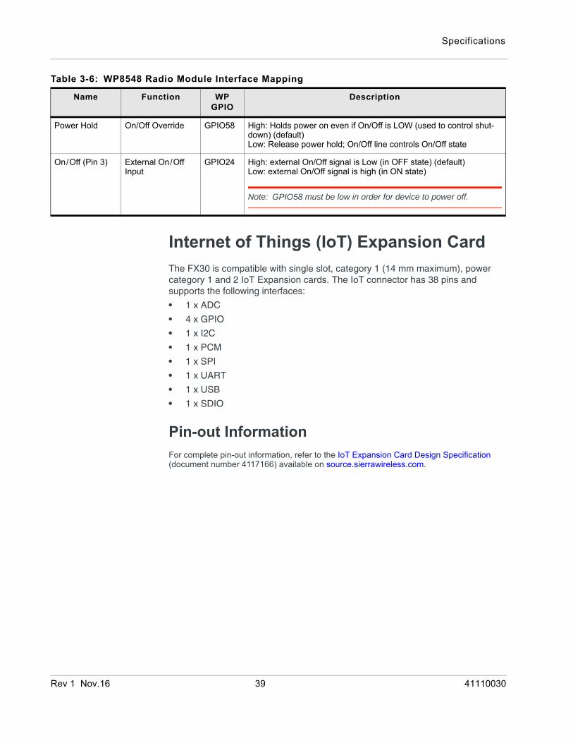
Internet of Things (IoT) Expansion CardThe FX30 is compatible with single slot, category 1 (14 mm maximum), power category 1 and 2 IoT Expansion cards. The IoT connector has 38 pins and supports the following interfaces:
• 1 x ADC
• 4 x GPIO
• 1 x I2C
• 1 x PCM
• 1 x SPI
• 1 x UART
• 1 x USB
• 1 x SDIO
Pin-out InformationFor complete pin-out information, refer to the IoT Expansion Card Design Specification (document number 4117166) available on source.sierrawireless.com.
Power Hold On/Off Override GPIO58 High: Holds power on even if On/Off is LOW (used to control shut-down) (default)Low: Release power hold; On/Off line controls On/Off state
On/Off (Pin 3) External On/Off Input
GPIO24 High: external On/Off signal is Low (in OFF state) (default)Low: external On/Off signal is high (in ON state)
Note: GPIO58 must be low in order for device to power off.
Table 3-6: WP8548 Radio Module Interface Mapping
Name Function WP GPIO
Description
Rev 1 Nov.16 39 41110030
Rev 1 Oct
4
4: Regulatory InformationImportant Information for North American Users
Warning: This equipment has been tested and found to comply with the limits for a Class A digital device, pursuant to part 15 of the FCC Rules. These limits are designed to provide reasonable protection against harmful interference when the equipment is operated in a commercial environment. This equipment generates, uses, and can radiate radio frequency energy and, if not installed and used in accordance with the instruction manual, may cause harmful interference to radio communications. Operation of this equipment in a residential area is likely to cause harmful interference, in which case the user will be required to correct the interference at his own expense. Changes or modifications to this device not expressly approved by Sierra Wireless could void the user's authority to operate this equipment.
RF ExposureIn accordance with FCC/IC requirements of human exposure to radio frequency fields, the radiating element shall be installed such that a minimum separation distance of 20 cm should be maintained between the antenna and the user's body.
Warning: This product is only to be installed by qualified personnel.
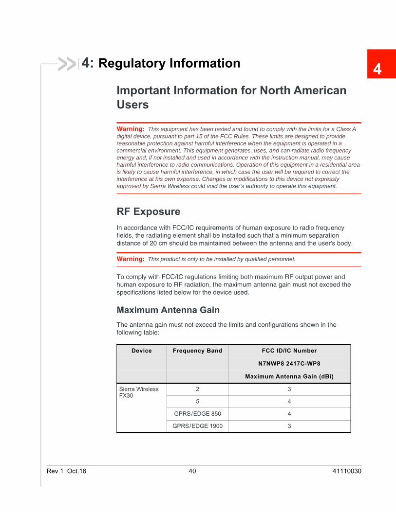
To comply with FCC/IC regulations limiting both maximum RF output power and human exposure to RF radiation, the maximum antenna gain must not exceed the specifications listed below for the device used.
Maximum Antenna GainThe antenna gain must not exceed the limits and configurations shown in the following table:
Device Frequency Band FCC ID/IC Number
N7NWP8 2417C-WP8
Maximum Antenna Gain (dBi)
Sierra Wireless FX30
2 3
5 4
GPRS/EDGE 850 4
GPRS/EDGE 1900 3
.16 40 41110030
Regulatory Information
EUSierra Wireless hereby declares the Sierra Wireless FX30 device is in compliance with the essential requirements and other relevant provisions of Directive 1999/5/EC.
The FX30 displays the CE mark.
Warning: Changes or modifications to this device not expressly approved by Sierra Wireless could void the user's authority to operate this equipment.
Warning: This product is only to be installed by qualified personnel.
Declaration of ConformityThe Declaration of Conformity made under Directive 1999/5/EC is available for viewing at: source.sierrawireless.com/resources/airlink/certification_and_type_approval/FX30_ce_declaration_of_conformity/.
WEEE Notice
If you purchased your Sierra Wireless FX30 in Europe, please return it to your dealer or supplier at the end of its life. WEEE products may be recognized by their wheeled bin label on the product label.
Rev 1 Oct.16 41 41110030
Rev 1 Oct
A
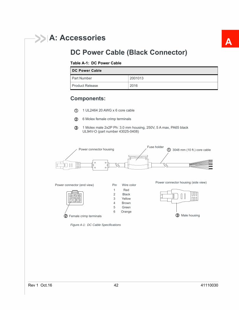
A: AccessoriesDC Power Cable (Black Connector)
Components:
Figure A-1: DC Cable Specifications
Table A-1: DC Power Cable
DC Power Cable
Part Number 2001013
Product Release 2016
1 UL2464 20 AWG x 6 core cable
6 Molex female crimp terminals
1 Molex male 2x2P Ph: 3.0 mm housing, 250V, 5 A max, PA65 black UL94V-O (part number 43025-0408)
1 2 34
Power connector (end view)Power connector housing (side view)
Pin Wire color1234
RedBlack
OrangeGreen
3048 mm (10 ft.) core cablePower connector housingFuse holder
Male housingFemale crimp terminals
5 6
56
YellowBrown
.16 42 41110030
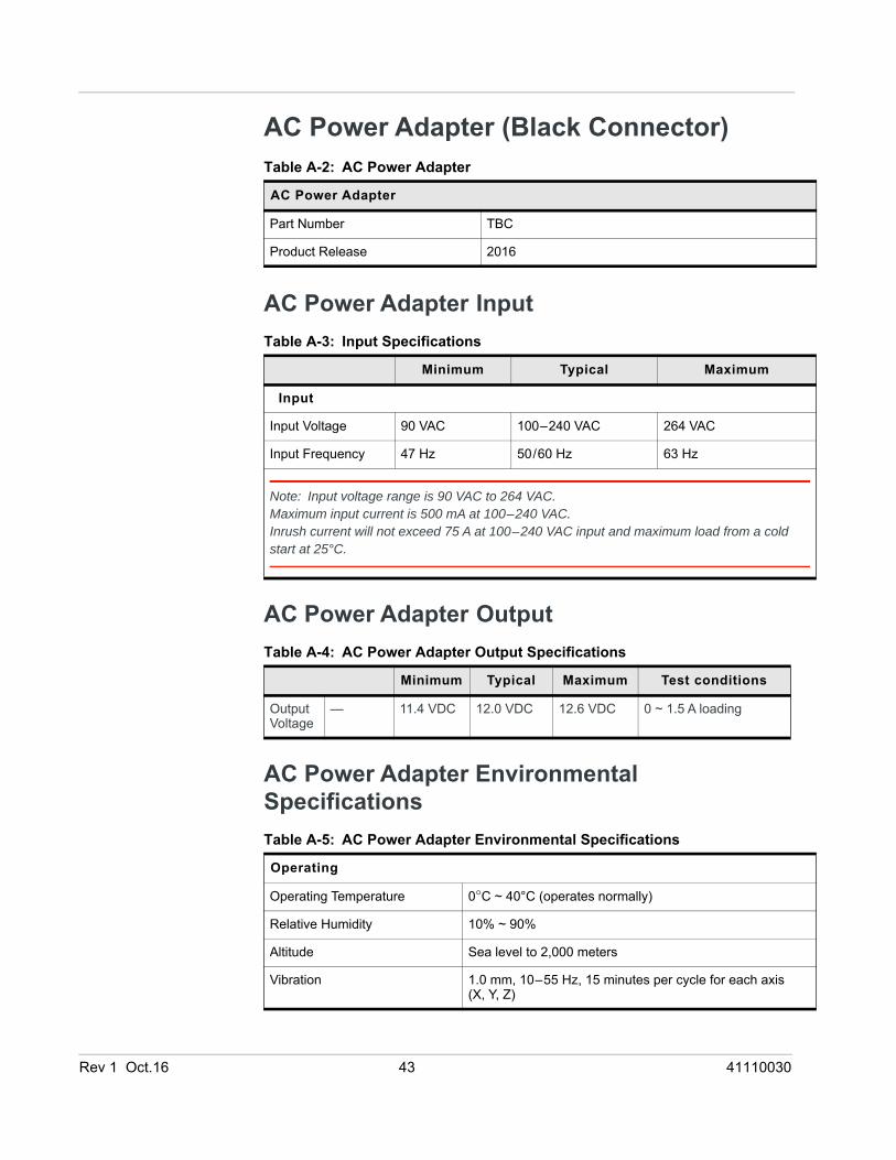
AC Power Adapter (Black Connector)
AC Power Adapter Input
AC Power Adapter Output
AC Power Adapter Environmental Specifications
Table A-2: AC Power Adapter
AC Power Adapter
Part Number TBC
Product Release 2016
Table A-3: Input Specifications
Minimum Typical Maximum
Input
Input Voltage 90 VAC 100–240 VAC 264 VAC
Input Frequency 47 Hz 50/60 Hz 63 Hz
Note: Input voltage range is 90 VAC to 264 VAC. Maximum input current is 500 mA at 100–240 VAC.Inrush current will not exceed 75 A at 100–240 VAC input and maximum load from a cold start at 25°C.
Table A-4: AC Power Adapter Output Specifications
Minimum Typical Maximum Test conditions
Output Voltage
— 11.4 VDC 12.0 VDC 12.6 VDC 0 ~ 1.5 A loading
Table A-5: AC Power Adapter Environmental Specifications
Operating
Operating Temperature 0°C ~ 40°C (operates normally)
Relative Humidity 10% ~ 90%
Altitude Sea level to 2,000 meters
Vibration 1.0 mm, 10–55 Hz, 15 minutes per cycle for each axis (X, Y, Z)
Rev 1 Oct.16 43 41110030

Sierra Wireless FX30 Hardware User Guide
AC Power Adapter Reliability and Quality ControlAC Power Adapter MTBF
When the power supply is operating within the limits of this specification, the MTBF is at least 200,000 hours at 25°C (MIL-HDBK-217F).
AC Power Adapter Safety StandardsThe power supply is certified with the following international regulatory standards:
AC Power Adapter EMC StandardsThe power supply meets the radiated and conducted emission requirements for EN55022, FCC Part 15, Class B, GB9254.
AC Power Adapter Hazardous Substances• EU Directive 2011/65/EU “RoHS”
• EU Directive 2012/19/EU “WEEE”
• REACH
Non-operating
Storage Temperature -30°C ~ 70°C
Relative Humidity 10% ~ 90%
Vibration and Shock MIL-STD-810D, method 514
Table A-6: AC Power Adapter Safety standards
Regulatory Agency
Country or Region
Certified Standard
UL USA Approved UL60950-1
GS Europe Approved EN60950-1
CE Europe Approved EN60950-1
SAA Australia Approved AS/NZS 60950
CCC China Approved GB4943
CUL Canada Approved CSA C22.2 NO.60950-1
Table A-5: AC Power Adapter Environmental Specifications (Continued)
Rev 1 Oct.16 44 41110030
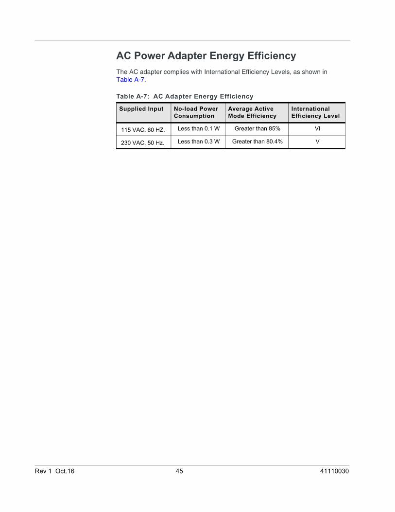
AC Power Adapter Energy EfficiencyThe AC adapter complies with International Efficiency Levels, as shown in Table A-7.
Table A-7: AC Adapter Energy Efficiency
Supplied Input No-load Power Consumption
Average Active Mode Efficiency
International Efficiency Level
115 VAC, 60 HZ. Less than 0.1 W Greater than 85% VI
230 VAC, 50 Hz. Less than 0.3 W Greater than 80.4% V
Rev 1 Oct.16 45 41110030
Rev 1 Oct.16 46 41110030
AAccessories, 7Analog input, 22Antenna
connecting, 15maximum gain, 40
CCable strain relief, 17Cables, connecting, 16Certification
Industry Standards, 30Mobile Network Operator, 31
Communicationcommand line prompt, using, 25
Current sink, 24
DDC cable wires, 18Digital output, 24
EEnvironmental Testing, 30Ethernet
LEDs, 26
FFeatures, 6
GGNSS, 32Grounding the chassis, 15
HHost Interfaces, 31
II / O Configuration, 20Input
analog, 22dry contact switch, 22on/off switch, 21
Installationconnect data cables, 16connect power cable, 17connecting antennas, 15fixed (with I/O), 20insert SIM cards, 9overview, 9tools and materials required, 9
IoT expansion card, 10
IP address, obtaining with command line prompt, 25
LLED
description of LED, 25LTE, bands supported, 31
MMTBF
AC adapter, 44
OOpen drain, 24Operating voltage, 31Output, digital, 24
PPinging the router with command line prompt, 25Power
connecting, 17connector, 17
Pull-up resistor, 22
RRegulatory information, 40Regulatory specifications, 44RF specifications, 15
SScrew Torque, 31SIM cards, insert, 9Specifications, 30
environmental, 30environmental testing, 30GNSS, 32Input / Output, 31regulatory, 44RF, 15
Standards, regulatory, 44
TTools required for install, 9
WWarranty, 7Wiring diagrams, 19
Index