Sierra Series 620S Fast-Floâ„¢ Insertion Mass - Sierra Instruments
42
Sierra Series 620S Fast-Flo ™ Insertion Mass Flow Meter Instruction Manual Part Number IM-62S 01/99 Revision B 5 Harris Court, Building L Monterey, CA 93940 (831) 373-0200 (800) 866-0200 Fax (831) 373-4402 http://www.sierrainstruments.com Sierra Instruments b.v. Bolstoen 30A 1046 AV Amsterdam The Netherlands +31(0)20-6145810 Fax +31(0)20-6145815
Transcript of Sierra Series 620S Fast-Floâ„¢ Insertion Mass - Sierra Instruments

Series 620S Instruction Manual Table of Contents
IM-62S-B 0-1
Sierra Series 620S Fast-Flo™
Insertion Mass Flow Meter
Instruction ManualPart Number IM-62S
01/99 Revision B
5 Harris Court, Building L Monterey, CA 93940(831) 373-0200 (800) 866-0200 Fax (831) 373-4402
http://www.sierrainstruments.com
Sierra Instruments b.v. Bolstoen 30A 1046 AV Amsterdam The Netherlands+31(0)20-6145810 Fax +31(0)20-6145815
Table of Contents Series 620S Instruction Manual
0-2 IM-62S-B
Customer NoticeSierra Instruments, Inc. is not liable for any damage or personal injury, whatsoever,resulting from the use of Sierra Instruments standard mass flow meters for oxygengas. You are responsible for determining if this mass flow meter is appropriate foryour oxygen application. You are responsible for cleaning the mass flow meter tothe degree required for your oxygen flow application.
© COPYRIGHT SIERRA INSTRUMENTS 1998No part of this publication may be copied or distributed, transmitted, transcribed, stored ina retrieval system, or translated into any human or computer language, in any form or byany means, electronic, mechanical, manual, or otherwise, or disclosed to third partieswithout the express written permission of Sierra Instruments. The information contained inthis manual is subject to change without notice.
TRADEMARKSFast-Flo™ and Smart Interface™ software are trademarks of Sierra Instruments, Inc.Other product and company names listed in this manual are trademarks or trade names oftheir respective manufacturers.
All Sierra products are Year 2000 compliant.

Series 620S Instruction Manual Table of Contents
IM-62S-B 0-3
Table of Contents
Chapter 1 IntroductionSeries 620S Mass Flow Meters......................................1-1
Using this Manual.................................................1-1Note and Safety Information.....................................1-2Receipt of System Components .. . . . . . . . . . . . . . . . . . . . . . . . . . . . . . . .1-2Technical Assistance..............................................1-2
The Series 620S Flow Sensing Principle...........................1-3Smart Electronics Features............................................1-4Enclosure Options .. . . . . . . . . . . . . . . . . . . . . . . . . . . . . . . . . . . . . . . . . . . . . . . . . . . .1-5Smart Interface Software..............................................1-5
Chapter 2 Installation and WiringInstallation Overview..................................................2-1
Site Selection.......................................................2-1Unobstructed Flow Requirements...............................2-2
Installation..............................................................2-3Wiring Connections .. . . . . . . . . . . . . . . . . . . . . . . . . . . . . . . . . . . . . . . . . . . . . . . . . .2-4
Input Power Wiring...............................................2-4Output Signal Wiring ... . . . . . . . . . . . . . . . . . . . . . . . . . . . . . . . . . . . . . . . . . .2-5Alarm Output Wiring..............................................2-7Remote Sensor Probe Wiring....................................2-8Range Selection Wiring...........................................2-9
Chapter 3 Operating InstructionsUsing the Smart Electronics Basic Features........................3-1
Using the Single-Digit LED for Programming.................3-2Using the LCD Display for Programming......................3-3Entering Alarm Parameters.......................................3-4K-factor Adjustment .. . . . . . . . . . . . . . . . . . . . . . . . . . . . . . . . . . . . . . . . . . . . .3-5User Full Scale Adjustment......................................3-6Time Response Delay Adjustment...............................3-7Totalizer Reset.....................................................3-7
Using the Smart Electronics Advanced Features...................3-9Voltage Zero Adjustment.........................................3-9Voltage Span Adjustment.........................................3-9Current Zero Adjustment........................................3-10Current Span Adjustment........................................3-10
Instrument Validation.................................................3-11Electronics Validation Procedure...............................3-12Sensor Validation Procedure....................................3-13

Table of Contents Series 620S Instruction Manual
0-4 IM-62S-B
Chapter 4 Troubleshooting and RepairTroubleshooting the Flow Meter.....................................4-1Obtaining a Return Material Authorization..........................4-3
Appendix A Product Specifications
List of Figures1-1. Series 620S Sensor Assembly ... . . . . . . . . . . . . . . . . . . . . . . . . . . .1-32-1. Recommended Pipe Length Requirements.................2-22-2. Wiring Access.................................................2-42-3. Input Power Connections....................................2-42-4. Output Signal Wiring.........................................2-52-5. Load Resistance Versus Input Voltage.....................2-62-6. Isolated 4-20 mA Current Loop Connections .... . . . . . . . . .2-62-7. Non-isolated 4-20 mA Current Loop Connections .......2-62-8. Isolated Alarm Output Connections.........................2-72-9. Non-isolated Alarm Output Connections...................2-72-10. Remote Electronics to Sensor Connections................2-82-11. Sensor J Box to Remote Enclosure Connections ..... . . . .2-82-12. Range Selection Wiring......................................2-93-1. Display/Keypad Commands.................................3-13-2. Electronics Validation Component Locations.............3-113-3. Sensor Validation Component Locations .................3-13
List of Tables3-1. Electronics Validation Results..............................3-133-2. Sensor Validation Results...................................3-14
Series 620S Instruction Manual Table of Contents
IM-62S-B 0-5
Warnings and Cautions
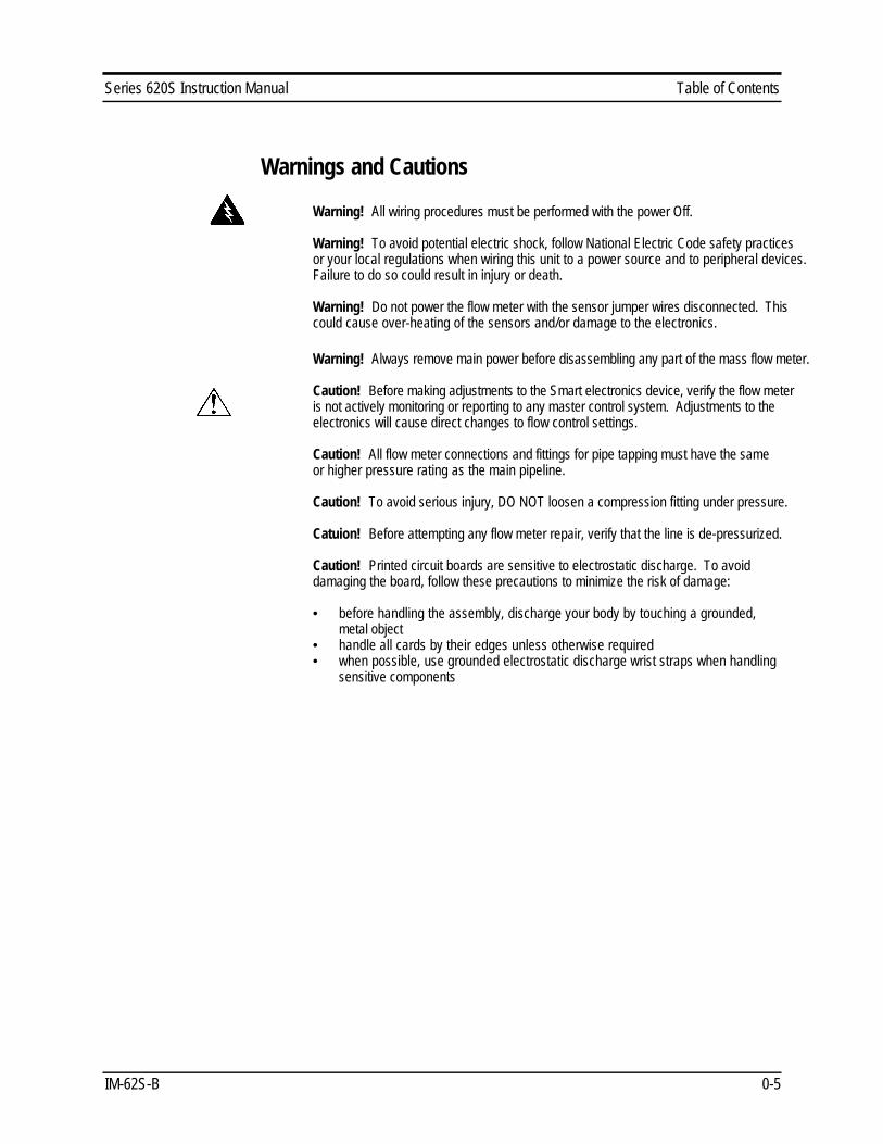
Warning! All wiring procedures must be performed with the power Off.
Warning! To avoid potential electric shock, follow National Electric Code safety practicesor your local regulations when wiring this unit to a power source and to peripheral devices.Failure to do so could result in injury or death.
Warning! Do not power the flow meter with the sensor jumper wires disconnected. Thiscould cause over-heating of the sensors and/or damage to the electronics.
Warning! Always remove main power before disassembling any part of the mass flow meter.
Caution! Before making adjustments to the Smart electronics device, verify the flow meteris not actively monitoring or reporting to any master control system. Adjustments to theelectronics will cause direct changes to flow control settings.
Caution! All flow meter connections and fittings for pipe tapping must have the sameor higher pressure rating as the main pipeline.
Caution! To avoid serious injury, DO NOT loosen a compression fitting under pressure.
Catuion! Before attempting any flow meter repair, verify that the line is de-pressurized.
Caution! Printed circuit boards are sensitive to electrostatic discharge. To avoiddamaging the board, follow these precautions to minimize the risk of damage:
• before handling the assembly, discharge your body by touching a grounded,metal object
• handle all cards by their edges unless otherwise required• when possible, use grounded electrostatic discharge wrist straps when handling
sensitive components

Table of Contents Series 620S Instruction Manual
0-6 IM-62S-B

Series 620S Instruction Manual Chapter 1 Introduction
IM-62S-B 1-1
Chapter 1 Introduction
Series 620S Fast-Flo™ Mass Flow MetersSierra’s Series 620S Smart Mass Flow Meter provides a reliablesolution for inert gas flow measurement applications. Low-flowsensitivity, fast response and outstanding rangeability have madethis model the instrument of choice for many critical gas flowapplications.
The Smart microprocessor-based transmitter integrates the func-tions of flow-range adjustment, meter validation and diagnostics ina probe-mounted or remote NEMA 4X (IP65) housing. Mass flowrate and totalized flow, as well as other configuration variables canbe displayed on the meter’s optional 2 x 12 backlit LCD panel. Themeter provides an optical/galvanic isolated flow output, two alarmoutputs and one contact input for range or gas selection. The pro-grammable transmitter is easily configured via RS-232 and Sierra’sSmart Interface software or through three push buttons built intothe device.
Depending on the probe length, the Series 620S is suitable forpipes or ducts from two inches up to 48 inches (DN50 up toDN1200). The Series 620S Mass Flow Meter’s simple installa-tion combines with an easy-to-use interface that provides quick setup, long term reliability and accurate mass flow measurement overa wide range of conditions.
Using This ManualThis manual provides the information you need to install and operatethe Series 620S Smart Insertion Mass Flow Meter. The four chap-ters of this manual cover these areas:• Chapter 1 includes the introduction and product description• Chapter 2 provides installation and wiring instructions• Chapter 3 describes system operation and programming• Chapter 4 covers troubleshooting and repair
The product specifications and dimensional drawings are found inAppendix A.
Chapter 1 Introduction Series 620S Instruction Manual
1-2 IM-62S-B
Note and Safety InformationWe use note, caution and warning statements throughout this bookto draw your attention to important information.
Warning! Caution! NoteThis statement appears withinformation that is important toprotect people and equipmentfrom damage. Pay very closeattention to all warnings thatapply to your application.
This statement appears withinformation that is importantfor protecting your equipmentand performance. Read andfollow all cautions that applyto your application.
This statement appears witha short message to alert youto an important detail.
Receipt of System ComponentsWhen receiving a Sierra mass flow meter, carefully check the out-side packing carton for damage incurred in shipment. If the cartonis damaged, notify the local carrier and submit a report to the factoryor distributor. Remove the packing slip and check that all orderedcomponents are present. Make sure any spare parts or accessoriesare not discarded with the packing material. Do not return anyequipment to the factory without a Return Material Authorization(RMA, see Chapter 4).
Technical AssistanceIf you encounter a problem with your flow meter, review the con-figuration information for each step of the installation, operation andsetup procedures. Verify that your settings and adjustments are con-sistent with factory recommendations. Refer to Chapter 4, Trouble-shooting, for specific information and recommendations.
If the problem persists after following the troubleshooting proce-dures outlined in Chapter 4, contact Sierra Instruments by fax or byE-mail ([email protected]). For phone support youmay call (800) 866-0200 or (831) 373-0200 between 8:00 a.m.and 5:00 p.m. PST. In Europe contact Sierra Instruments b.v. at+31 20 6145810. When contacting Technical Support, make sure toinclude this information:
• the flow range, serial number and Sierra order number andmodel number (all marked on the meter nameplate)
• if possible, the firmware version (visible at start up on themeter display)
• the problem you are encountering and any corrective action taken• application information (gas, pressure, temperature, piping
configuration)
Series 620S Instruction Manual Chapter 1 Introduction
IM-62S-B 1-3
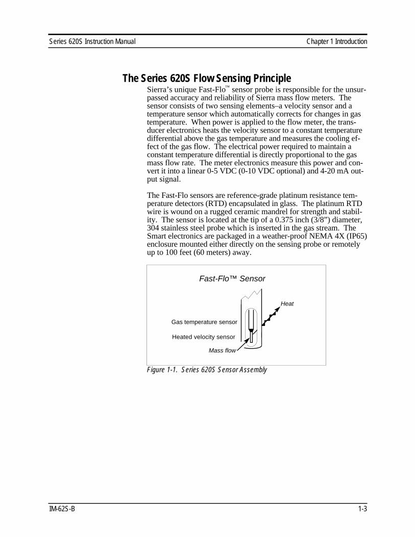
The Series 620S Flow Sensing PrincipleSierra’s unique Fast-Flo™ sensor probe is responsible for the unsur-passed accuracy and reliability of Sierra mass flow meters. Thesensor consists of two sensing elements–a velocity sensor and atemperature sensor which automatically corrects for changes in gastemperature. When power is applied to the flow meter, the trans-ducer electronics heats the velocity sensor to a constant temperaturedifferential above the gas temperature and measures the cooling ef-fect of the gas flow. The electrical power required to maintain aconstant temperature differential is directly proportional to the gasmass flow rate. The meter electronics measure this power and con-vert it into a linear 0-5 VDC (0-10 VDC optional) and 4-20 mA out-put signal.
The Fast-Flo sensors are reference-grade platinum resistance tem-perature detectors (RTD) encapsulated in glass. The platinum RTDwire is wound on a rugged ceramic mandrel for strength and stabil-ity. The sensor is located at the tip of a 0.375 inch (3/8”) diameter,304 stainless steel probe which is inserted in the gas stream. TheSmart electronics are packaged in a weather-proof NEMA 4X (IP65)enclosure mounted either directly on the sensing probe or remotelyup to 100 feet (60 meters) away.
Gas temperature sensor
Heat
Heated velocity sensor
Fast-Flo™ Sensor
Mass flow
Figure 1-1. Series 620S Sensor Assembly

Chapter 1 Introduction Series 620S Instruction Manual
1-4 IM-62S-B
Smart Electronics FeaturesInstrument ValidationTwo simple tests offer full “field-validation” of your Smart massflow meter. The first test checks the system electronics, linearizationand microprocessor functionality. This is performed by injecting aknown input value and confirming that the flow meter outputs the ex-pected value. The second test verifies that the instrument’s primarysensing elements have not drifted or shifted from their original cali-bration. This is accomplished by measuring the resistance of the ve-locity and temperature sensors and comparing the results to theNIST-traceable calibration data provided with the flow meter. To-gether, these tests confirm that your meter is working correctly andthe calibration variables did not drift, shift or change values.
Dual Range or Dual Gas Calibration (Optional)Select one of two factory calibrated flow ranges using a simple ex-ternal customer-supplied single contact closure.
User Full Scale Flow RateField-configure from 50% to 100% of the factory full scale setting(factory full scale is normally set to 125% of the user-specified maxi-mum flow rate). This adjustment can be made for each flow range.
AlarmsProgram high and low or window alarm limits independently for eachflow range. The solid state contacts are isolated with one common.
K-Factor CorrectionChange the calibration correction factor to compensate for flow pro-file disturbances or specific application conditions. The K-factor is amultiplication factor applied to the linearized flow signal. You mayset the K-factor individually for each flow range.
Dual Output SignalsSmart flow meters offer two separate linear output signals propor-tional to flow, 0-5 VDC (0-10 VDC optional) and 4-20 mA. The4-20 mA output can be field-configured as an active loop poweredby the flow meter or an optically isolated passive loop requiring anexternal power supply.

Series 620S Instruction Manual Chapter 1 Introduction
IM-62S-B 1-5
TotalizerWith the optional LCD display, actual mass flow appears on line 1and the totalized flow on line 2 both in the user-specified engineer-ing units. The totalizer counts only the selected range and whenranges are switched, the value of the non-selected range is stored inmemory. You may reset the totalizer using the 3 function buttonsmounted on the PCA or by using a hand-held magnet.
Zero and Span OutputsValidate and adjust the settings to ensure output circuits are correct.
Time Response DelaySelect from a low response for faster tracking to a high responsefor a smoother output.
Enclosure OptionsFlow meter electronics are available mounted directly to the flowbody, or remotely mounted up to 100 feet (60 meters) away. Theelectronics housing may be used indoors or outdoors.
Display options include a 2 x 12 character LCD display of mass flowrate including totalized mass, or a single-digit LED located on the de-vice printed circuit board. Local operation and reconfiguration is ac-complished using the three push buttons operated via finger touch.Smart electronics include nonvolatile memory that stores all configu-ration information. The memory allows the flow meter to functionimmediately upon power up, or after an interruption in power.
Smart Interface™ SoftwareSierra’s Smart Interface Windows™-based software is available forconnecting your PC directly to the mass flow meter. An RS-232serial cable along with floppy disks containing the program andsystem files are available from the factory. See the Smart InterfaceUser Guide included with the software for operating instructions.(Order code for this package is 620-SIP.)

Chapter 1 Introduction Series 620S Instruction Manual
1-6 IM-62S-B

Series 620S Instruction Manual Chapter 2 Installation
IM-62S-B 2-1
Chapter 2 Installation
Installation OverviewThe Series 620S flow meter is factory calibrated to the specific pipesize shown on the meter’s Certificate of Calibration. The factorycalibration eliminates the task of calculating the average flow acrossthe pipe to determine the correct insertion depth. Simply insert theflow meter sensor to the centerline position of the pipe. (If the pipesize differs from the meter’s calibrated size, return the meter to thefactory for re-calibration.)
When selecting an installation site, make sure that:
1. Line pressure and temperature will not exceed the flow meterrating. Temperature should not vary more than 120°F (50°C)from the calibration temperature. Line pressure should not varymore than 50 psi (3.4 bar) around the calibrated pressure.
2. The location meets the required minimum number of pipe
diameters upstream and downstream of the sensor head (seeFigure 2-1).
3. Safe and convenient access with adequate clearance. Also, verify
the meter is located where the gas is clean and dry and the meteris calibrated for the gas to be measured.
4. For remote installations, verify the supplied cable length is suffi-
cient to connect the flow meter sensor to the remote electronics.(Do not extend or shorten the supplied cable between the probeand the electronics.)
Also, before installation check your flow system for anomaliessuch as:• leaks• valves or restrictions in the flow path that could create distur-
bances in the flow profile that might cause unexpected flow rateindications
• heaters that might cause rapid excursions in the measured temperature
Chapter 2 Installation Series 620S Instruction Manual
2-2 IM-62S-B
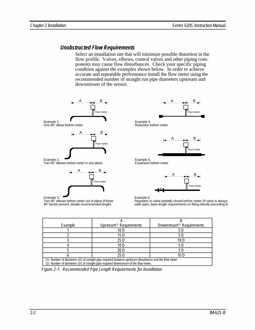
Unobstructed Flow RequirementsSelect an installation site that will minimize possible distortion in theflow profile. Valves, elbows, control valves and other piping com-ponents may cause flow disturbances. Check your specific pipingcondition against the examples shown below. In order to achieveaccurate and repeatable performance install the flow meter using therecommended number of straight run pipe diameters upstream anddownstream of the sensor.
Flow meter
A B
Example 1.One 90° elbow before meter
Flow meter
A B
Example 2.Two 90° elbows before meter in one plane
Flow meter
A B
Example 3.Two 90° elbows before meter out of plane (if three 90° bends present, double recommended length)
Flow meter
A B
Example 4.Reduction before meter
Flow meter
A B
Example 5.Expansion before meter
Example 6.Regulator or valve partially closed before meter (If valve is always wide open, base length requirements on fitting directly preceding it)
Flow meter
A B
ExampleA
Upstream(1) RequirementsB
Downstream(2) Requirements1 10 D 5 D2 15 D 5 D3 25 D 10 D4 10 D 5 D5 20 D 5 D6 25 D 10 D
(1) Number of diameters (D) of straight pipe required between upstream disturbance and the flow meter.(2) Number of diameters (D) of straight pipe required downstream of the flow meter.
Figure 2-1. Recommended Pipe Length Requirements for Installation

Series 620S Instruction Manual Chapter 2 Installation
IM-62S-B 2-3
InstallationUse the following data as a guide to prepare the pipe for flow meterinsertion. Refer to a standard code for all pipe tapping operations.The following instructions are general in nature and intended forguideline purposes only.
1. Turn off the flow of process gas. Verify that the line is notpressurized.
2. Confirm that the installation site meets the minimum upstream
and downstream pipe diameter requirements. See Figure 2-1. 3. Use a cutting torch or sharp cutting tool to tap into the pipe. The
pipe opening must be at least .375 inches in diameter. (Do notattempt to insert the sensor probe through a smaller hole.)
1. Remove all burrs from the tap. Rough edges may cause flow
profile distortions that could affect flow meter accuracy. Also,obstructions could damage the sensor assembly when insertinginto the pipe.
1. Mount the 3/8 inch compression fitting on the pipe. Make sure
this connection is within ± 5° perpendicular to the pipe centerline. 1. When installed, cap the fitting. Run a static pressure check on the
connection. If pressure loss or leaks are detected, repair the con-nection and re-test.
2. Insert the sensor probe through the
compression fitting into the pipe.The correct insertion depth placesthe larger hole in the probe at thepipe’s centerline. Do not forceinto the pipe.
1. Align the sensor head using the flow direction indicator. Adjust
the indicator parallel to the pipe and pointing downstream in thedirection of flow.
1. Tighten the compression fitting to lock the flow meter in posi-
tion. When the compression fitting is tightened, the position ispermanent (unless using Teflon ferrules).
Caution!All flow meter connectionsand fittings must have the
same or higher pressurerating as the main pipeline.
Flowdirectionindicatorpointsdownstream
Flow Pipe centerline
Caution!To avoid serious injury,
DO NOT loosen thecompression fitting
under pressure.

Chapter 2 Installation Series 620S Instruction Manual
2-4 IM-62S-B
Wiring ConnectionsThe NEMA 4X enclosure contains an integral wiring compartmentwith one dual strip terminal block for power and signal connectionsand one dual strip terminal block for sensor connections. The en-closure has one 1/2 inch female NPT conduit entry. The terminaldesignations are labeled inside the enclosure cover.
Smart electronicsand wiring connectionsinside cover
To access components:1. Loosen 4 screws.2. Remove cover.
1/2 inch FNPT
conduitentry
Figure 2-2. Wiring Access
Input Power WiringDepending on the flow meter configuration, connect 11 to 18 VDCor 18 to 30 VDC (625 mA load, maximum) as shown below. Con-firm power configuration before applying power. See the flowmeter nameplate for input power rating.
TB2PWR (+)
PWR (–)
+
–Power & signal
12
1516
Sensor
12
56
TB1
Figure 2-3. Input Power Connections
Warning!All wiring procedures
must be performedwith the power Off.
Warning!To avoid potential electric
shock, follow NationalElectric Code safety prac-
tices or your local codewhen wiring this unit to apower source and to pe-
ripheral devices. Failure todo so could result in injury
or death.
Series 620S Instruction Manual Chapter 2 Installation
IM-62S-B 2-5
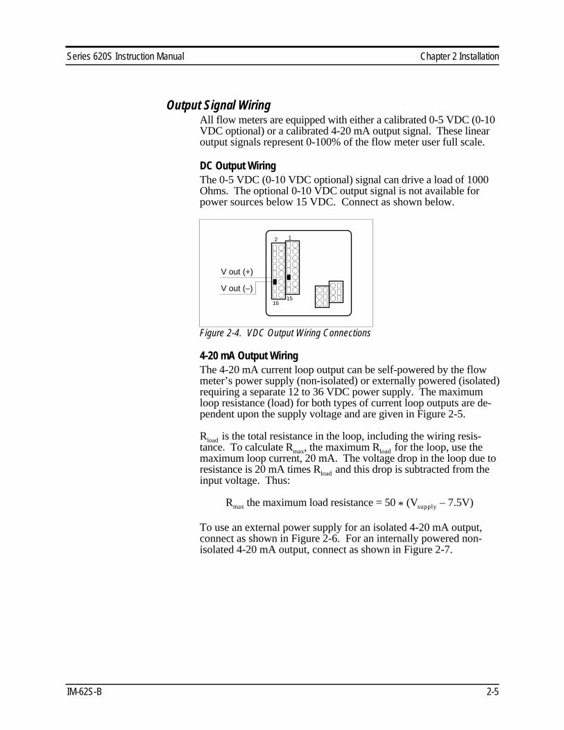
Output Signal WiringAll flow meters are equipped with either a calibrated 0-5 VDC (0-10VDC optional) or a calibrated 4-20 mA output signal. These linearoutput signals represent 0-100% of the flow meter user full scale.
DC Output WiringThe 0-5 VDC (0-10 VDC optional) signal can drive a load of 1000Ohms. The optional 0-10 VDC output signal is not available forpower sources below 15 VDC. Connect as shown below.
V out (+)
V out (–)
12
1516
Figure 2-4. VDC Output Wiring Connections
4-20 mA Output WiringThe 4-20 mA current loop output can be self-powered by the flowmeter’s power supply (non-isolated) or externally powered (isolated)requiring a separate 12 to 36 VDC power supply. The maximumloop resistance (load) for both types of current loop outputs are de-pendent upon the supply voltage and are given in Figure 2-5.
Rload is the total resistance in the loop, including the wiring resis-tance. To calculate Rmax, the maximum Rload for the loop, use themaximum loop current, 20 mA. The voltage drop in the loop due toresistance is 20 mA times Rload and this drop is subtracted from theinput voltage. Thus:
Rmax the maximum load resistance = 50 * (Vsupply – 7.5V)
To use an external power supply for an isolated 4-20 mA output,connect as shown in Figure 2-6. For an internally powered non-isolated 4-20 mA output, connect as shown in Figure 2-7.

Chapter 2 Installation Series 620S Instruction Manual
2-6 IM-62S-B
Figure 2-5. Load Resistance Versus Input Voltage
R load4-20 out (+)
4-20 out (–)
12 VDCto
36 VDC
Current
– +
12
1516
Figure 2-6. Isolated 4-20 mA Current Loop Connections
4-20 out (+)
V out (–)
AUX PWR OUTJumper
CurrentR load
12
1516
(Common)
Figure 2-7. Non-isolated 4-20 mA Current Loop Connections
Vsupply Rmax
(Volts) (Ohms)11 (min) 175
12 22515 37518 52524 82530 1,125
36 (max) 1,425
Series 620S Instruction Manual Chapter 2 Installation
IM-62S-B 2-7
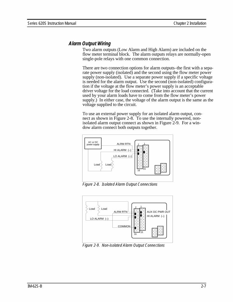
Alarm Output WiringTwo alarm outputs (Low Alarm and High Alarm) are included on theflow meter terminal block. The alarm outputs relays are normally-opensingle-pole relays with one common connection.
There are two connection options for alarm outputs–the first with a sepa-rate power supply (isolated) and the second using the flow meter powersupply (non-isolated). Use a separate power supply if a specific voltageis needed for the alarm output. Use the second (non-isolated) configura-tion if the voltage at the flow meter’s power supply is an acceptabledriver voltage for the load connected. (Take into account that the currentused by your alarm loads have to come from the flow meter’s powersupply.) In either case, the voltage of the alarm output is the same as thevoltage supplied to the circuit.
To use an external power supply for an isolated alarm output, con-nect as shown in Figure 2-8. To use the internally powered, non-isolated alarm output connect as shown in Figure 2-9. For a win-dow alarm connect both outputs together.
ALRM RTN
Load Load
LO ALARM (–)
HI ALARM (–)
AC or DCpower supply 12
1516
Figure 2-8. Isolated Alarm Output Connections
ALRM RTNLoadLoad
LO ALARM (–)HI ALARM (–)
COMMON
AUX DC PWR OUT
12
1516
Figure 2-9. Non-isolated Alarm Output Connections

Chapter 2 Installation Series 620S Instruction Manual
2-8 IM-62S-B
Remote Sensor Probe WiringUse only factory supplied cables when connecting the sensorprobe to a remotely mounted flow meter enclosure. The electron-ics, sensors and interconnecting cables supplied by Sierra Instru-ments are calibrated as a complete precision mass flow circuit.
To connect the sensor probe to a remotely mounted electronics en-closure, see Figure 2-10. To make wiring connections from asensor probe junction box to a remotely mounted enclosure, seeFigure 2-11.
Velocitysensor
REDGREEN
ORANGEWHITEBLACK
Temperaturesensor
Remote enclosure Sensor
probe
56
12
Figure 2-10. Remote Electronics Enclosure to Sensor Connections
REDGREEN
ORANGEWHITEBLACK
Remote enclosure
Sensorprobe
junction box
12
56
Figure 2-11. Sensor Junction Box to Remote Enclosure Connections
Caution!Changing the length of
cables or interchangingsensors or sensor wiring
will affect the accuracy ofthe flow meter. You can-
not add or subtract wirelength without returningthe meter to the factory
for re-calibration.

Series 620S Instruction Manual Chapter 2 Installation
IM-62S-B 2-9
Range Selection WiringIf your meter is equipped with an optional second range calibration,connect a contact switch as shown below. When the switch is closedthe device changes to Range 2. Open the switch to return to Range1.
Figure 2-12. Range Selection Wiring

Chapter 2 Installation Series 620S Instruction Manual
2-10 IM-62S-B

Series 620S Instruction Manual Chapter 3 Operation
IM-62S-B 3-1
Chapter 3 OperationUsing the Smart Electronics Basic Features
Three push buttons allow selection and adjustment of the basic userfunctions. Use the push buttons to enter:
• alarm parameters• change the user full scale• adjust the K-factor• adjust the time response speed• reset the totalizer
You may view parameters using the optional LCD front panel displayor by selecting functions on the single-digit LED and viewing themeter’s 0-5 VDC output with a digital voltmeter (DVM).
Before making changes or adjustments:For meters with the optional LCD display, remove the enclosure coverto access the Smart electronics device. Press the FUNCTION key toview and record the factory settings. When pressing FUNCTION theoptional LCD display prompts for a password, press FUNCTIONagain to skip the password and review the current settings. (To makechanges, at the password prompt press the UP arrow until 11 is dis-played, press FUNCTION to continue.)
For flow meters without the display, remove the enclosure cover toaccess the Smart electronics device. Connect the DVM as describedon the following pages and record the factory-set parameters.
After 12 seconds of non-activity during programming, the meter re-turns to the Run Mode with any new settings immediately in effect.For units without a LCD front panel display: if the unit “times-out”when entering a new parameter, press the FUNCTION button onlyto resume adjustments.
Smart electronics device located inside the flow meter enclosure. Remove the cover to enter parameters using the device buttons.
Single digit LED
FUNCTIONUPDOWN
Figure 3-1. Display/Keypad Commands
Caution!Before making any ad-
justment to the Smartelectronics device, verifythe flow meter is not ac-tively monitoring or re-
porting to any mastercontrol system. Any ad-
justment to the electronicswill cause direct changes
to flow control settings.
Chapter 3 Operation Series 620S Instruction Manual
3-2 IM-62S-B
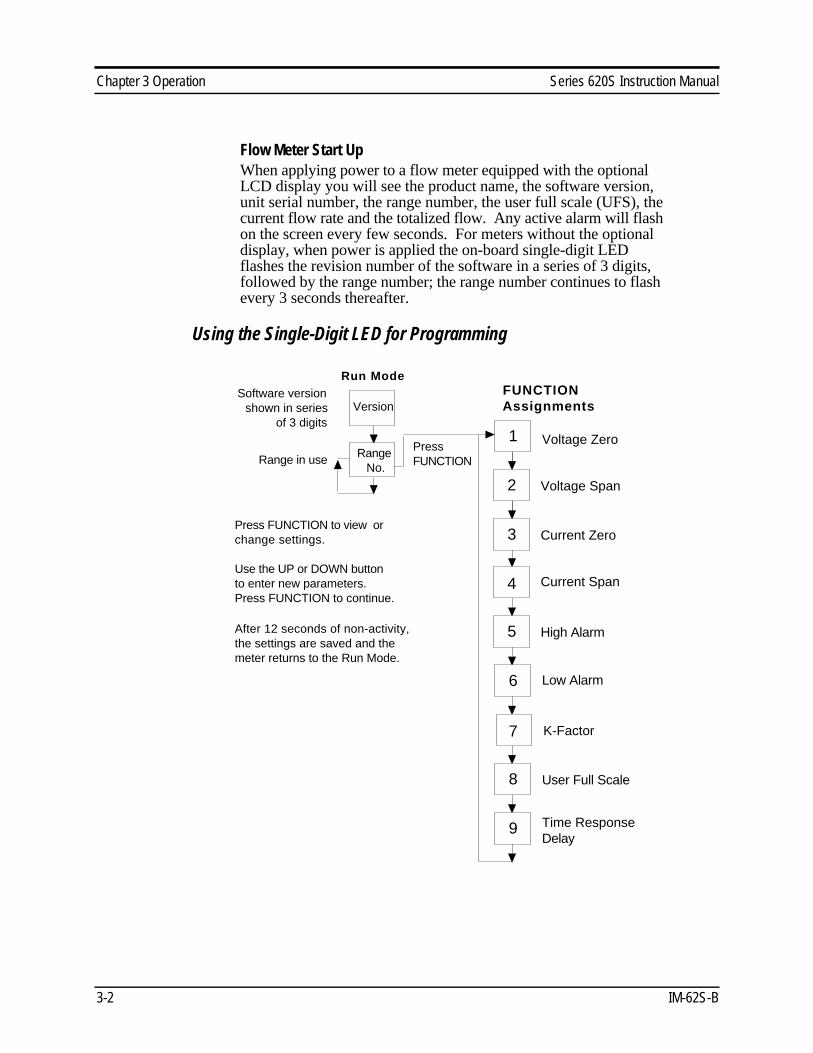
Flow Meter Start UpWhen applying power to a flow meter equipped with the optionalLCD display you will see the product name, the software version,unit serial number, the range number, the user full scale (UFS), thecurrent flow rate and the totalized flow. Any active alarm will flashon the screen every few seconds. For meters without the optionaldisplay, when power is applied the on-board single-digit LEDflashes the revision number of the software in a series of 3 digits,followed by the range number; the range number continues to flashevery 3 seconds thereafter.
Using the Single-Digit LED for Programming
FUNCTION AssignmentsVersion
Voltage Span
Voltage Zero
High Alarm
Current Span
User Full Scale
K-Factor
Range in use
Software version shown in series
of 3 digits1
Run Mode
Press FUNCTION to view or change settings.
Use the UP or DOWN button to enter new parameters. Press FUNCTION to continue.
After 12 seconds of non-activity, the settings are saved and the meter returns to the Run Mode.
Current Zero
Low Alarm
Time Response Delay
Press FUNCTION
2
3
4
5
6
7
8
9
Range No.

Series 620S Instruction Manual Chapter 3 Operation
IM-62S-B 3-3
Using the LCD Display for Programming
VersionSerial No.
SierraFlow Meter
Current flow rate Totalized flow
Span Volts
Zero Volts
High Alarm
Span mA
User FS
K-Factor
FlowTotal Flow
FlowAlarm
Range No.UFS
Current range in use User full scale
Current flow rateIf an alarm is active
(will flash)
Software versionMeter serial number
Flow meter model
Start Up Screens
Password
Total Reset?
To view settings, press FUNCTION twice, skipping the password. To change settings, press FUNCTION, enter the password, 11, press FUNCTION to continue.
Use the UP or DOWN button to enter new parameters. Press FUNCTION to continue.
After 12 seconds of non-activity, the settings are saved and the meter returns to the Run Mode.
For units with the optional front panel LCD display, you must correctly enter the password to change parameters.
Zero mA
Low Alarm
Time Resp.
Press FUNCTION
LCD DisplayFUNCTIONS
Run Mode
Chapter 3 Operation Series 620S Instruction Manual
3-4 IM-62S-B
Entering Alarm ParametersUse the High Alarm and Low Alarm function to set or adjust alarmtrip points. The alarms have a minimum hysteresis of 3% to avoid"chattering." When setting a window alarm, the alarm setpoints mustbe at least twice the hysteresis value apart. We suggest at least a 10%separation between window alarm setpoints. If you choose not touse the high alarm for a specific alarm function, Sierra recommendsthat you set the high alarm at 100% of the user full scale settingwhich creates an “over-range” indicator. Your flow meter will con-tinue to indicate flow and generate a signal if the flow is over themaximum range, but will not operate within the specified accuracy.
Entering Alarms with the LCD DisplayEnter alarms setpoints directly in engineering units.
1. Select the desired range. Press FUNCTION, enter the pass-word. Press FUNCTION until High Alarm or Low Alarm ap-pears on the display.
2. Use the UP or DOWN arrow keys to enter the high or low alarm
setpoint value in engineering units. 3. Press FUNCTION to advance to the next option, or after 12
seconds of non-activity the meter returns to the Run Mode andthe new parameters are in effect.
Entering Alarms without the LCD DisplayWhen using a DVM to set alarms, the setpoint is a percentage of theflow meter’s user full scale.
VOLTS = (ALARM PERCENT x 5.0)
If you want to alarm at 25% of user full scale, used in Step 3 below,press the UP or DOWN button until 1.25 VDC is present on theDVM. If you want to alarm at 75% of user full scale, press the UPor DOWN button until 3.75 VDC is present on the DVM.
1. Set the DVM to voltage mode and connect between Vout+ andVout– on the flow meter terminal block.
2. Select the desired range. Press the FUNCTION button until a solid
“5” (high alarm) or solid “6” (low alarm) appears on the LED. 3. Adjust the UP or DOWN button until the DVM indicates the de-
sired setpoint voltage as described above. 4. Press FUNCTION again to advance to the next option, or after
12 seconds of non-activity the meter returns to the Run Modeand the new alarm parameters are in effect.
Caution!The flow meter mustnot be reporting ormeasuring gas flowduring adjustments.
Series 620S Instruction Manual Chapter 3 Operation
IM-62S-B 3-5
K-Factor AdjustmentEntering a K-factor adjusts the meter’s output signal without affect-ing the factory calibration curve. Use the K-factor calibration offsetfor additional flow profile compensation (the factory includes an ini-tial flow profile correction in the calibration curve of the unit).
Entering a K-factor with the LCD DisplayA K-factor value of 1.000 means the output value is not affected andis the factory default setting. You may enter any number from0.500 to 5.000.
1. Select the desired range. Press FUNCTION, enter the password.Press FUNCTION until K-factor appears on the display.
2. Use the UP or DOWN arrow keys to enter the desired K-factor
value in engineering units. 3. Press FUNCTION to advance to the next option, or after 12
seconds of non-activity the meter returns to the Run Mode andthe new K-factor is in effect.
Entering a K-factor without the LCD DisplayA K-factor value of 1.000 VDC means the output value is not af-fected and is the factory default setting. You may enter any valuefrom 0.500 to 5.000 VDC in Step 3 below. If the device indicatedoutput is 3.0 VDC and you know it should be 3.8 VDC then youcould “force” the output to the desired 3.8 VDC by adjusting the K-factor to indicate 1.27 VDC (1.27 = 3.8/3.0). Use this formula todetermine the desired K-factor voltage:
VOLTS = DESIRED/ INDICATED
1. Set the DVM to voltage mode and connect between Vout+ andVout– on the flow meter terminal block.
2. Select the desired range. Press the FUNCTION button until a
solid “7” appears on the LED. 3. Adjust the UP or DOWN button until the DVM indicates the de-
sired K-factor value as described above. 4. Press FUNCTION to advance to the next option, or after 12
seconds of non-activity the meter returns to the Run Mode andthe new K-factor is in effect.
Caution!The flow meter mustnot be reporting ormeasuring gas flowduring adjustments.

Chapter 3 Operation Series 620S Instruction Manual
3-6 IM-62S-B
User Full Scale AdjustmentThe user full scale (UFS) feature adjusts the flow meter output rangeanywhere within 50% to 100% of the factory full scale (FFS). Thisfeature allows you to re-range the voltage or current output of themeter to accommodate different flow rates. When entering a newuser full scale setting for Range 2, it cannot be less than 10% of theRange 1 user full scale setting.
Changing the User Full Scale with the LCD DisplayThe factory full scale is shown on the flow meter label. If you want aUFS equal to the FFS, adjust the display to match the FFS. If youwant to use 50% of FFS, adjust the display to read 50% of the FFS.
1. Select the desired range. Press FUNCTION, enter the password.Press FUNCTION until User Full Scale appears on the display.
2. Use the UP or DOWN arrow keys to enter the desired UFS
value in engineering units. 3. Press FUNCTION to advance to the next option, or after 12
seconds of non-activity the meter returns to the Run Mode andthe new UFS is in effect.
Changing the User Full Scale without the LCD DisplayIf the FFS is set to 11,000 sfpm and UFS is set to output 5.0 VDC,or 100%, the flow meter will indicate 5.0 VDC when 11,000 sfpmis present on the probe. If you want 6,000 sfpm for UFS, used inStep 3 below, adjust the UFS to 6000/11000 or 54.55% of factoryfull scale. Adjust the voltage to 2.73 VDC (2.73 = 5 x .5455).Use this formula to determine the desired UFS voltage:
VOLTS = 5 x (User Full Scale / Factory Full Scale)
1. Set the DVM to voltage mode and connect between Vout+ andVout– on the flow meter terminal block.
2. Select the desired range. Press the FUNCTION button until a
solid “8” appears on the LED. 3. Adjust the UP or DOWN button until the DVM indicates the de-
sired user full scale as described above. 4. Press FUNCTION to advance to the next option, or after 12
seconds of non-activity the meter returns to the Run Mode andthe new UFS is in effect.
Caution!The flow meter mustnot be reporting ormeasuring gas flowduring adjustments.

Series 620S Instruction Manual Chapter 3 Operation
IM-62S-B 3-7
Time Response Delay Adjustment
Changing the Time Response Delay with the LCD Display1. Press FUNCTION, enter the password. Press FUNCTION
until Time Response appears on the display. 2. Use the UP or DOWN button to adjust the time response delay
from 0.10 to 7.2 seconds. 3. Press FUNCTION again to advance to the next option, or after
12 seconds of non-activity the meter returns to the Run Modeand the new time response setting is in effect.
Changing the Time Response Delay without the LCD Display1. Set the DVM to voltage mode and connect between Vout+ and
Vout– on the flow meter terminal block. Select the desiredrange. Press the FUNCTION button until a solid “9” appearson the LED.
2. Adjust the UP or DOWN button until the DVM indicates the de-
sired voltage (as shown in the following table).
VoltsIndicatedon DVM
TimeResponse(Seconds)
VoltsIndicatedon DVM
TimeResponse(Seconds)
VoltsIndicatedon DVM
TimeResponse(Seconds)
VoltsIndicatedon DVM
TimeResponse(Seconds)
0.5 0.1 1.0 0.3 1.5 0.5 2.0 0.72.5 1.2 3.0 1.8 3.5 2.4 4.0 3.64.5 4.8 5.0 7.2
3. Press FUNCTION to advance to the next option, or after 12
seconds of non-activity the meter returns to the Run Mode andthe new time response delay setting is in effect.
Totalizer ResetIf your device is equipped with the optional LCD display, reset thetotalizer using the keypad. If you are unable to open the flow meterenclosure, use a magnet to reset the totalizer as shown below.
1. Select the desired range. Enter thepassword. Press FUNCTION untilTotal Reset? appears on the display.
2. Press the UP button and then the
DOWN button until the displayreads “Resetting Totalizer.”
Hold magnet here for reset

Chapter 3 Operation Series 620S Instruction Manual
3-8 IM-62S-B

Series 620S Instruction Manual Chapter 3 Operation
IM-62S-B 3-9
Using the Smart Electronics Advanced FeaturesZero and span (Function 1 through 4) can be used to validate systemoperation and calibrate the digital to analog signals on the Smartelectronics device. Additionally, these functions can compensate forresistance in long signal cables connected to your data collection orindicating system.
You must use a certified digital voltmeter to adjust zero and span asthe voltmeter acts as a standard. We recommend recording the currentvalues as shown on the LCD display or DVM before making anychanges to the zero and span settings. Note: when adjusting zero thevoltage signal will be driven to 0 VDC and when adjusting span thevoltage signal will be driven to 5 VDC (or 10 VDC).
Voltage Zero AdjustmentIf needed, use Zero Volts (Function 1) to adjust the 0-5 VDC outputto 0.0 VDC, or optional 0-10 VDC to 0.0 VDC.
1. Set the DVM to voltage mode and connect between Vout+ and Vout–. 2. Press FUNCTION, enter the password (if so equipped). Press
FUNCTION until Zero Volts appears on the LCD display or a solid“1” appears on the LED. Adjust the UP or DOWN button until theDVM indicates between 0 and .01 VDC (no less than 0.005). TheSmart electronics device cannot drive negative values.
3. After 12 seconds of non-activity, the meter returns to the Run
Mode and the new parameter is in effect.
Voltage Span AdjustmentIf needed, use Span Volts (Function 2) to adjust the 0-5 VDC outputto 5.0 VDC, or optional 0-10 VDC to 10 VDC.
1. Set the DVM to voltage mode and connect between Vout+ and Vout–. 2. Press FUNCTION, enter the password (if so equipped). Press
FUNCTION until Span Volts appears on the LCD display or asolid “2” appears on the LED. Adjust the UP or DOWN buttonuntil the DVM, indicates between 4.99 and 5.01 VDC. (For 0-10VDC devices, the target value is 9.99 to 10.01.)
3. After 12 seconds of non-activity, the meter returns to the Run
Mode and the new parameter is in effect.
Caution!Adjusting zero or
span will affect metercalibration.

Chapter 3 Operation Series 620S Instruction Manual
3-10 IM-62S-B
Note: when adjusting zero the current signal will be driven to 4 mA andwhen adjusting span the current signal will be driven to 20 mA. We recom-mend recording the current values before making any changes to the currentzero or span settings.
Current Zero AdjustmentIf needed, use Zero mA (Function 3) to adjust the 4-20 mA output to4.0 mA.
1. Disconnect the 4-20 mA (+) loop wire. Set the DVM to currentmode and connect the positive lead to the wire you just discon-nected. Connect the negative lead to the 4-20 mA (–) on theflow meter terminal block.
2. Press FUNCTION, enter the password (if so equipped). Press
FUNCTION until Zero mA appears on the LCD display or a solid“3” appears on the LED. Adjust the UP or DOWN button until theDVM indicates between 3.95 and 4.05 mA. Set DVM back to volt-age mode when adjustment is complete.
3. After 12 seconds of non-activity, the meter returns to the Run
Mode and the new parameter is in effect.
Current Span AdjustmentIf needed, use Span mA (Function 4) to adjust the 4-20 mA outputto 20.0 mA.
1. Disconnect the 4-20 mA (+) loop wire. Set the DVM to currentmode and connect the positive lead to the wire you just discon-nected. Connect the negative lead to 4-20 (–) on the flow meterterminal block.
2. Press FUNCTION, enter the password (if so equipped). Press
FUNCTION until Span mA appears on the LCD display or a solid“4” appears on the LED. Adjust the UP or DOWN button until theDVM indicates between 19.95 and 20.05 mA. Set DVM back tovoltage mode when adjustment is complete.
3. After 12 seconds of non-activity, the meter returns to the Run
Mode and the new parameter is in effect.
Caution!Adjusting zero or
span will affect metercalibration.

Series 620S Instruction Manual Chapter 3 Operation
IM-62S-B 3-11
Instrument ValidationSystem electronics are verified by injecting a known input value andconfirming that the flow meter outputs the expected value. This testconfirms that the microprocessor, analog to digital and digital toanalog converters, the linearizer and the display are working prop-erly. Sensor validation is accomplished by measuring the resistanceof the velocity and temperature sensors and comparing the results tothe NIST-traceable calibration data provided with the flow meter.These tests confirm that your meter is working correctly and thecalibration variables did not drift, shift or change values.
To perform the instrument validation procedures you will need theseitems:
• certified digital multimeter with minimum 4 character resolution,accuracy of at least ± 0.1% of range
• Calibration Certificate supplied with the flow meter• small pot adjusting tool (screwdriver)
Before beginning the validation procedures, review Figure 3-2 andFigure 3-3 to familiarize yourself with the component locations.
Smart Electronics Device
J1 CAL/RUN jumper. Place in the CAL position for validation, return to RUN position for normal operation.
CALRUN
VR3
J1
Potentiometer VR3
Figure 3-2. Electronics Validation Component Locations
Chapter 3 Operation Series 620S Instruction Manual
3-12 IM-62S-B
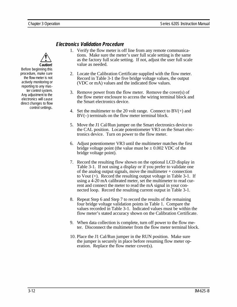
Electronics Validation Procedure1. Verify the flow meter is off line from any remote communica-
tions. Make sure the meter’s user full scale setting is the sameas the factory full scale setting. If not, adjust the user full scalevalue as needed.
2. Locate the Calibration Certificate supplied with the flow meter.
Record in Table 3-1 the five bridge voltage values, the output(VDC or mA) values and the indicated flow values.
3. Remove power from the flow meter. Remove the cover(s) of
the flow meter enclosure to access the wiring terminal block andthe Smart electronics device.
4. Set the multimeter to the 20 volt range. Connect to BV(+) and
BV(–) terminals on the flow meter terminal block. 5. Move the J1 Cal/Run jumper on the Smart electronics device to
the CAL position. Locate potentiometer VR3 on the Smart elec-tronics device. Turn on power to the flow meter.
6. Adjust potentiometer VR3 until the multimeter matches the first
bridge voltage point (the value must be ± 0.002 VDC of thebridge voltage point).
7. Record the resulting flow shown on the optional LCD display in
Table 3-1. If not using a display or if you prefer to validate oneof the analog output signals, move the multimeter + connectionto Vout (+). Record the resulting output voltage in Table 3-1. Ifusing a 4-20 mA calibrated meter, set the multimeter to read cur-rent and connect the meter to read the mA signal in your con-nected loop. Record the resulting current output in Table 3-1.
8. Repeat Step 6 and Step 7 to record the results of the remaining
four bridge voltage validation points in Table 1. Compare thevalues recorded in Table 3-1. Indicated values must be within theflow meter’s stated accuracy shown on the Calibration Certificate.
9. When data collection is complete, turn off power to the flow me-
ter. Disconnect the multimeter from the flow meter terminal block. 10. Place the J1 Cal/Run jumper in the RUN position. Make sure
the jumper is securely in place before resuming flow meter op-eration. Replace the flow meter cover(s).
Caution!Before beginning thisprocedure, make sure
the flow meter is notactively monitoring orreporting to any mas-
ter control system.Any adjustment to theelectronics will causedirect changes to flow
control settings.

Series 620S Instruction Manual Chapter 3 Operation
IM-62S-B 3-13
Calibration Certificate Values Validation Test Results
SamplePoint
BridgeVoltage
IndicatedFlow
Output(V or mA)
IndicatedFlow(LCD)
FlowMeterStated
Accuracy
Output(V or mA)
FlowMeterStated
Accuracy
0%
25%
50%
75%
100%
Table 3-1. Electronics Validation Results
Sensor Validation Procedure1. Locate the Ro temperature (measured resistance at 0°C) value and
the Alpha value shown on the Calibration Certificate supplied withthe flow meter.
2. Turn off power to the flow meter. Allow a 6 minute
cool-down before continuing. 3. Remove the cover of the flow meter enclosure to access the sensor
connection points. Remove the four-position jumper from J5, J6,J7 and J8 as shown below.
Smart Electronics Device
Remove jumper, measure on RIGHT ROW of pins
J5 temperatureJ6 temperatureJ7 velocityJ8 velocity
Figure 3-3. Sensor Validation Component Location
Warning!Do not power the flowmeter with the sensorjumper disconnected.
This could causeover-heating of the
sensors and/or dam-age to the electronics.

Chapter 3 Operation Series 620S Instruction Manual
3-14 IM-62S-B
4. Set the multimeter to read Ohms in the 2K range. Connect the
multimeter to terminals J5 and J6 (temperature sensor). Measurethe resistance between J5 and J6 and record the temperature sen-sor resistance (in Ohms) in Table 3-2.
5. Set the multimeter to read in the 200 Ohm range. Connect the
multimeter to terminals J7 and J8 (velocity sensor). Measure theresistance between J7 and J8 and record the velocity sensor resis-tance (in Ohms) in Table 3-2.
6. Use the measured resistance values and the Ro and Alpha values
from the Calibration Certificate to calculate the temperature foreach sensor as follows:
T = R – R
Alpha x R
T = degrees Celsius R = measured sensor resistance R = resistance at 0° C (from the Calibration Certificate) Alpha = value unique to each sensor (from the Calibration Certificate)
o
o
Whereo
7. Compare the results recorded in Table 3-2. The sensors are
validated if they are within 10 degrees Celsius of each other. 8. Disconnect the multimeter and replace the four-position jumper on
the sensor terminals. Make sure the jumper is securely inplace before applying power. Replace cover.
Temperature SensorResistance
T(from equation)
Velocity SensorResistance
T(from equation)
Table 3-2. Sensor Validation Results

Series 620S Instruction Manual Chapter 4 Troubleshooting & Repair
IM-62S-B 4-1
Chapter 4 Troubleshooting and Repair
Troubleshooting the Flow MeterBegin hardware troubleshooting by verifying the following facilitiesissues are correct. These areas impact system operation and must becorrected prior to performing any flow meter inspections.
1. Verify the incoming power to the flow meter is present and ofthe correct voltage and polarity.
2. Check the flow meter wiring for correct connections as de-
scribed in Chapter 2. 3. Verify the flow meter is installed with the correct number of up-
stream and downstream pipe diameters as shown on page 2-2. 4. Verify the flow direction indicator is correctly aligned pointing
downstream of flow. 5. Make sure there are no leaks in the line being measured. After verifying the factors above, follow the troubleshooting proce-dures outlined on the next page. If you need to return the flow meterto the factory, see the page 4-3 for Return Material Authorization(RMA) and shipping instructions.
Flow Meter CalibrationSierra Instruments maintains fully equipped, quality controlled FlowCalibration Metrology Laboratories for re-calibration. These labo-ratories have ISO 9001 certification. If the flow body or electronicshave been damaged or if you simply want to have the flow meter re-calibrated, contact the factory for shipping instructions. Calibrationmust be performed by qualified personnel using NIST-traceableequipment.
Warning!Always remove main power
before disassembling anypart of the mass flow meter.
Caution!Before attempting any flowmeter repair, verify that the
line is not pressurized..
Chapter 4 Troubleshooting & Repair Series 620S Instruction Manual
4-2 IM-62S-B
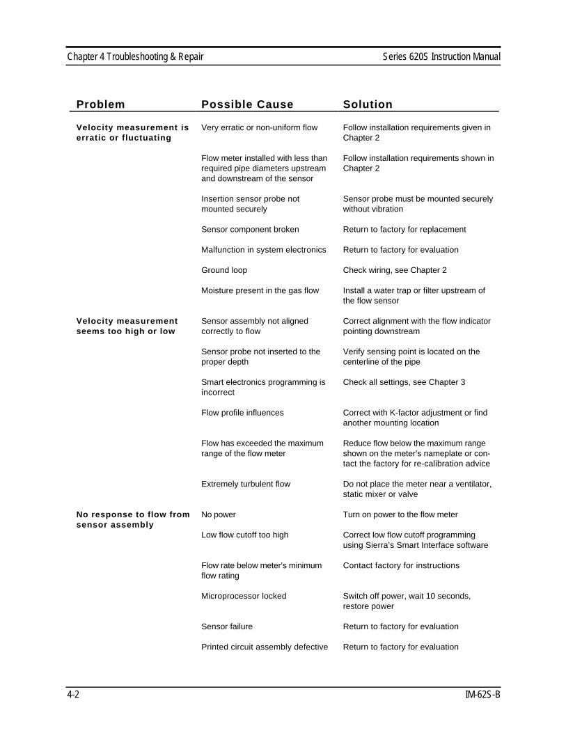
Problem Possible Cause Solution
Velocity measurement iserratic or fluctuating
Very erratic or non-uniform flow Follow installation requirements given inChapter 2
Flow meter installed with less thanrequired pipe diameters upstreamand downstream of the sensor
Follow installation requirements shown inChapter 2
Insertion sensor probe notmounted securely
Sensor probe must be mounted securelywithout vibration
Sensor component broken Return to factory for replacement
Malfunction in system electronics Return to factory for evaluation
Ground loop Check wiring, see Chapter 2
Moisture present in the gas flow Install a water trap or filter upstream ofthe flow sensor
Velocity measurementseems too high or low
Sensor assembly not alignedcorrectly to flow
Correct alignment with the flow indicatorpointing downstream
Sensor probe not inserted to theproper depth
Verify sensing point is located on thecenterline of the pipe
Smart electronics programming isincorrect
Check all settings, see Chapter 3
Flow profile influences Correct with K-factor adjustment or findanother mounting location
Flow has exceeded the maximumrange of the flow meter
Reduce flow below the maximum rangeshown on the meter’s nameplate or con-tact the factory for re-calibration advice
Extremely turbulent flow Do not place the meter near a ventilator,static mixer or valve
No response to flow fromsensor assembly
No power Turn on power to the flow meter
Low flow cutoff too high Correct low flow cutoff programmingusing Sierra’s Smart Interface software
Flow rate below meter’s minimumflow rating
Contact factory for instructions
Microprocessor locked Switch off power, wait 10 seconds,restore power
Sensor failure Return to factory for evaluation
Printed circuit assembly defective Return to factory for evaluation

Series 620S Instruction Manual Chapter 4 Troubleshooting & Repair
IM-62S-B 4-3
Obtaining a Return Material AuthorizationBefore returning any Series 620S Mass Flow Meter to the factory,you must obtain a Return Material Authorization (RMA) form fromSierra Instruments Customer Service. Have your model number andserial number available when you call. Contact Customer Service at:
(800) 866-0200 or (831) 373-0200 in the U.S.or +31(0)20-6145810 in Europe.
Return shipments to:
USA HeadquartersSierra Instruments Service Department5 Harris Court, Building WMonterey, CA 93940Attn: RMA #
European HeadquartersSierra Instruments b.v. Service DepartmentBolstoen 30A1046 AV Amsterdam, The Netherlands
When returning a component, include this information:• a note describing the problem• the model and serial number and the RMA number• corrective action to be accomplished at the factory• a contact name and phone number• complete return shipping instructions (the flow meter cannot be
delivered to post office boxes)

Chapter 4 Troubleshooting & Repair Series 620S Instruction Manual
4-4 IM-62S-B

Series 620S Instruction Manual Appendix A Specifications
IM-62S-B A-1
Appendix A Product SpecificationsOperating SpecificationsGases Air, nitrogen and other non-combustible, non-corrosive gases
Mass Flow Rates 0 to 200 sfpm (0 to 1 nmps) minimum, 0 to 20,000 sfpm (0 to 100 nmps)maximum for air and nitrogen (maximum full scale varies with gas)
Dual Calibration User-selectable dual ranges or two different gases (the user full scale forRange 2 two cannot be less than 10% of the full scale for Range 1)
Gas Pressure 150 psig (10 barg) at 80°C (176°F)
Pressure Drop Negligible
Gas & Ambient Temperature Gas.............................14° to 176°F (–10° to 80°C)Ambient......................32° to 122°F (0° to 50°C)
Power Requirements 11 to 18 VDC (regulated), 625 mA maximum18 to 30 VDC (regulated), 625 mA maximum
Output Signal Linear 0-5 VDC (0-10 VDC optional) proportional to point mass flow rate orvelocity, 1000 Ohms minimum load resistance, and linear 4-20 mA proportional topoint mass flow rate or velocity, 700 Ohms maximum resistance (power supplydependent), optically isolated (isolation is an input-to-output isolation of 1500 VACfor 1 minute)
Alarms User-adjustable low, high or window alarmsDeadband adjustable with Smart Interface™ softwareRelay rating...............Maximum 42 VAC or 42 VDC, 140 mA, 27 Ohm maxi-mum on-resistance, optically isolated (isolation is an input-to-output isolationof 1500 VAC for 1 minute)
Display Alphanumeric 2 x 12 digit backlit LCDAdjustable variables via on-board membrane buttons or with Smart InterfacesoftwareAdjustable variables...............Full scale adjustment (50 to 100%)
Time delay response (0.1 to 7.2 seconds)Correction factor setting (0.5 to 5)Zero and span adjustments
Totalizer Eight digits (99,999,999) in engineering units, resetable by user
Software Smart Interface™ Windows™-based software, minimum 8 MB of RAM,preferred 16 MB of RAM, RS-232 communication
Performance SpecificationsAccuracy ± 1% of full scale + 0.5% RDG
Repeatability ± 0.24% of full scale
Temperature Coefficient ± 0.02% of reading per °F within ± 50°F of customer specified conditions± 0.03% of reading per °F within ± 50°F to 100°F of customer specified conditions±0.04% of reading per °C within ± 25°C of customer specified conditions±0.06% of reading per °C within ± 25°C to 50°C of customer specified conditions
Pressure Coefficient 0.02% per psi
Response Time 250 milliseconds to 63% of final velocity value
Physical SpecificationsWetted Materials Probe: 304SS, epoxy, ceramic, Viton
Enclosure NEMA 4X (IP65) powder-coated cast aluminum enclosure
Mounting (optional) 3/8-inch tube compression fitting with 1/2-inch male NPT
Certifications CE approved

Appendix A Specifications Series 620S Instruction Manual
A-2 IM-62S-B
Mounting Dimensions
Standard Enclosure - Side View
Remote Enclosure - Side View
Enclosure-Junction Box - Side View
Standard Enclosure - Front View
Length Chartfor all Views
Code L
L04 4.0(101.6)
L06 6.0(152.4)
L09 9.0(228.6)
L13 13.0(330.2)
L18 18.0(457.2)
L24 24.0(609.6)
Remote Enclosure - Front View
Enclosure-Junction Box - Front View