Siemens Safety Integrated · SIMATIC S7-1200 with Safety Integrated …unique, innovative and...
40
Unrestricted / © Siemens Industry Inc. 2015. All Rights Reserved. www.usa.siemens.com/safety Siemens Safety Integrated … Take a safe step into the future Machine Safety Life-Cycle Engineered with TIA Portal
Transcript of Siemens Safety Integrated · SIMATIC S7-1200 with Safety Integrated …unique, innovative and...

Unrestricted / © Siemens Industry Inc. 2015. All Rights Reserved. www.usa.siemens.com/safety
Siemens Safety Integrated… Take a safe step into the future
Machine Safety Life-Cycle
EngineeredwithTIA Portal

Unrestricted/ © Siemens Industry Inc. 2015. All Rights Reserved.Page 2
Cutting disc > Cutting off
Transport rollers > Crushing and shearing
Clamping plates > Crushing
Chips > Cutting, penetrating
Risk assessment Risk reduction Proof
The necessary steps towards a safe machine can be illustrated with a process chain.
Machine SafetySafety Process Chain

Unrestricted/ © Siemens Industry Inc. 2015. All Rights Reserved.Page 3
Machine SafetyAre Risk Assessments Required?
Risk assessment Risk reduction Proof
DIRECTIVE 2006/42/EC(Machinery Directive)
European Union : USA:
NFPA 79 ANSI B11.19 ANSI / RIA 15.06 ANSI ASSE Z244.1
YES! All new & revised machine safety standards state that a “Risk assessment” MUST be performedYES! All new & revised machine safety standards state that a “Risk assessment” MUST be performed

Unrestricted/ © Siemens Industry Inc. 2015. All Rights Reserved.Page 4
Machine SafetyRisk Assessment Process
The following standards should be applied for the techniques to evaluate and assess these risks:
For USA: ANSI B11.0 - 2010, Safety of Machinery; General Requirements And Risk Assessment.
For Europe: EN ISO 12100 "Safety of machinery – basic terminology, general principles for design – risk assessment & risk reduction“
Unrestricted/ © Siemens Industry Inc. 2015. All Rights Reserved.Page 5
Risk assessment Risk reduction Proof
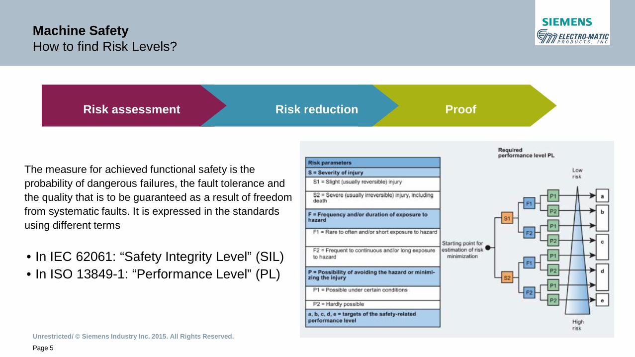
The measure for achieved functional safety is theprobability of dangerous failures, the fault tolerance andthe quality that is to be guaranteed as a result of freedomfrom systematic faults. It is expressed in the standardsusing different terms
• In IEC 62061: “Safety Integrity Level” (SIL)• In ISO 13849-1: “Performance Level” (PL)
Machine SafetyHow to find Risk Levels?
Unrestricted/ © Siemens Industry Inc. 2015. All Rights Reserved.Page 6
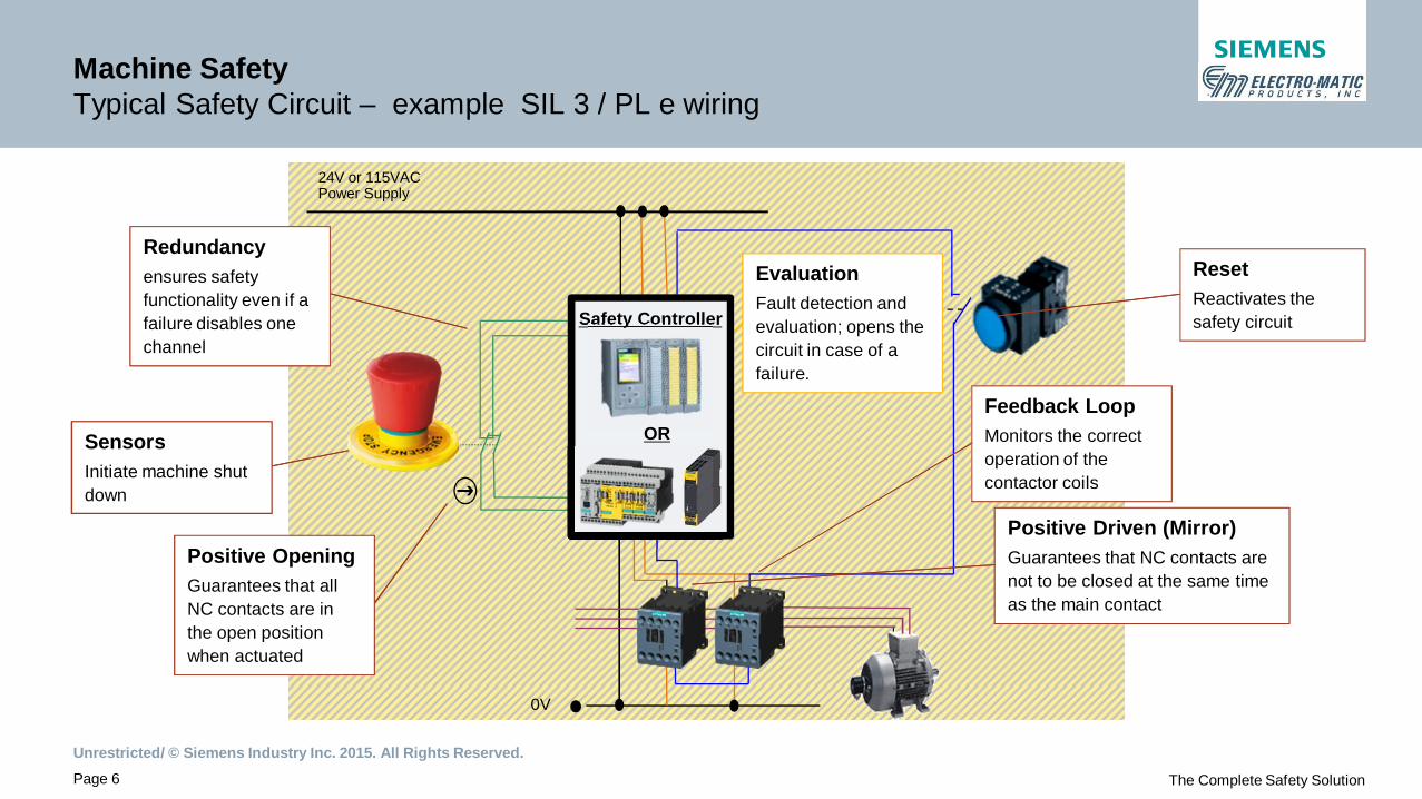
Machine SafetyTypical Safety Circuit – example SIL 3 / PL e wiring
24V or 115VACPower Supply
0V
SensorsInitiate machine shutdown
Positive OpeningGuarantees that allNC contacts are inthe open positionwhen actuated
Redundancyensures safetyfunctionality even if afailure disables onechannel
EvaluationFault detection andevaluation; opens thecircuit in case of afailure.
Positive Driven (Mirror)Guarantees that NC contacts arenot to be closed at the same timeas the main contact
Feedback LoopMonitors the correctoperation of thecontactor coils
ResetReactivates thesafety circuit
The Complete Safety Solution
Safety Controller
OR
Unrestricted/ © Siemens Industry Inc. 2015. All Rights Reserved.Page 7
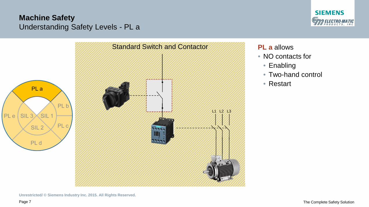
Standard Switch and ContactorStandard Switch and Contactor
Machine SafetyUnderstanding Safety Levels - PL a
PL a allows• NO contacts for
• Enabling• Two-hand control• Restart
L1 L2 L3
The Complete Safety Solution

Unrestricted/ © Siemens Industry Inc. 2015. All Rights Reserved.Page 8
24 VDC
0 VDC
Ope
n
Clo
sed
Machine SafetyUnderstanding Safety Levels - PL b
PL b requires• Sensors with positive
opening contacts
L1 L2 L3
The Complete Safety Solution

Unrestricted/ © Siemens Industry Inc. 2015. All Rights Reserved.Page 9
AndAnd
• Sensors with positiveopening contacts
• Safety evaluation unit ratedto SIL 1
• Feedback loop fromcontactor’s NC contacts
24 VDC
0 VDC
Ope
n
Clo
sed
Machine SafetyUnderstanding Safety Levels - PL c / SIL 1
PL c / SIL 1 requires
ON
L1 L2 L3
Q1
The Complete Safety Solution
Unrestricted/ © Siemens Industry Inc. 2015. All Rights Reserved.Page 10
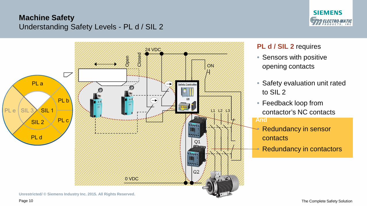
AndAnd
• Sensors with positiveopening contacts
• Safety evaluation unit ratedto SIL 2
• Feedback loop fromcontactor’s NC contacts
• Redundancy in sensorcontacts
• Redundancy in contactors
24 VDC
0 VDC
Ope
n
Clo
sed
Machine SafetyUnderstanding Safety Levels - PL d / SIL 2
PL d / SIL 2 requires
ON
L1 L2 L3
Q1
Q2
The Complete Safety Solution
Unrestricted/ © Siemens Industry Inc. 2015. All Rights Reserved.Page 11
AndAnd
24 VDC
0 VDC
Ope
n
Clo
sed
ON
L1 L2 L3
Q1
Q2
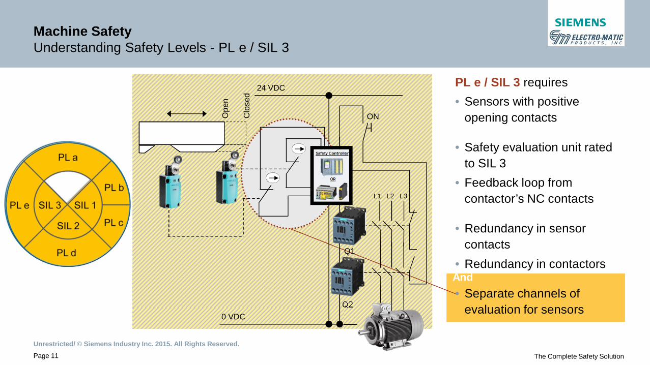
• Sensors with positiveopening contacts
• Safety evaluation unit ratedto SIL 3
• Feedback loop fromcontactor’s NC contacts
• Redundancy in sensorcontacts
• Redundancy in contactors
• Separate channels ofevaluation for sensors
Machine SafetyUnderstanding Safety Levels - PL e / SIL 3
PL e / SIL 3 requires
The Complete Safety Solution
Unrestricted / © Siemens Industry Inc. 2015. All Rights Reserved. www.usa.siemens.com/safety
SIMATIC Safety Integrated… Take a safe step into the future
Machine Safety Life-Cycle
EngineeredwithTIA Portal

Unrestricted/ © Siemens Industry Inc. 2015. All Rights Reserved.Page 13
SIMATIC Safety IntegratedProven Track Record
2000 2010 2015 2020
Next Generation of SIMATIC Safety IntegratedSafety Advanced in TIA Portal
DistributedSafetyS7-300F/400F WinAC RTX F
F-SystemsS7-400FH
STEP 7 SafetyAdvanced V11
STEP 7 SafetyAdvanced V12
ET 200SP
3/2014
STEP 7 SafetyAdvanced V13S7-1500F
1980 1990
S5-110F S5-115F S5-95F
S7-1200F
NFPA79 allowsSafety PLC’s

Unrestricted/ © Siemens Industry Inc. 2015. All Rights Reserved.Page 14
SIMATIC Safety IntegratedFrom standard to fail-safe automation in 3 easy steps
Detect Evaluate Respond
Sensors CPU & ProgramPeriphery Periphery
Standard PLC
Sensors CPU & ProgramPeriphery Periphery Actuators
Actuators& F-Sensors & F-Peripherie & F-Peripherie& F-Program
Communication
Hard-/Firmware Standard CPUStandard I/OStep1 Hard-& Firmware upgrade
Fail-safe I/O-modulesStandard communication
via PROFIBUS or PROFINETStep2 PROFIsafe
F-
F-CPU
User program Standard programSTEP7
Safety programSTEP7 and Safety AdvancedStep 3 F-Program
SafetyPLC
Detect Evaluate Response

Unrestricted/ © Siemens Industry Inc. 2015. All Rights Reserved.Page 15
SIMATIC Safety IntegratedSafety Software - One engineering for all fail-safe controllers
One engineering system
One fail-safe program Modular Controllers PC-based Controllers
STEP 7 Safety
ET 200F S7-300F S7-400F S7-1200F/S7-1500F
Fail-safe S7-CPU WinAC RTX F
Unrestricted/ © Siemens Industry Inc. 2015. All Rights Reserved.Page 16
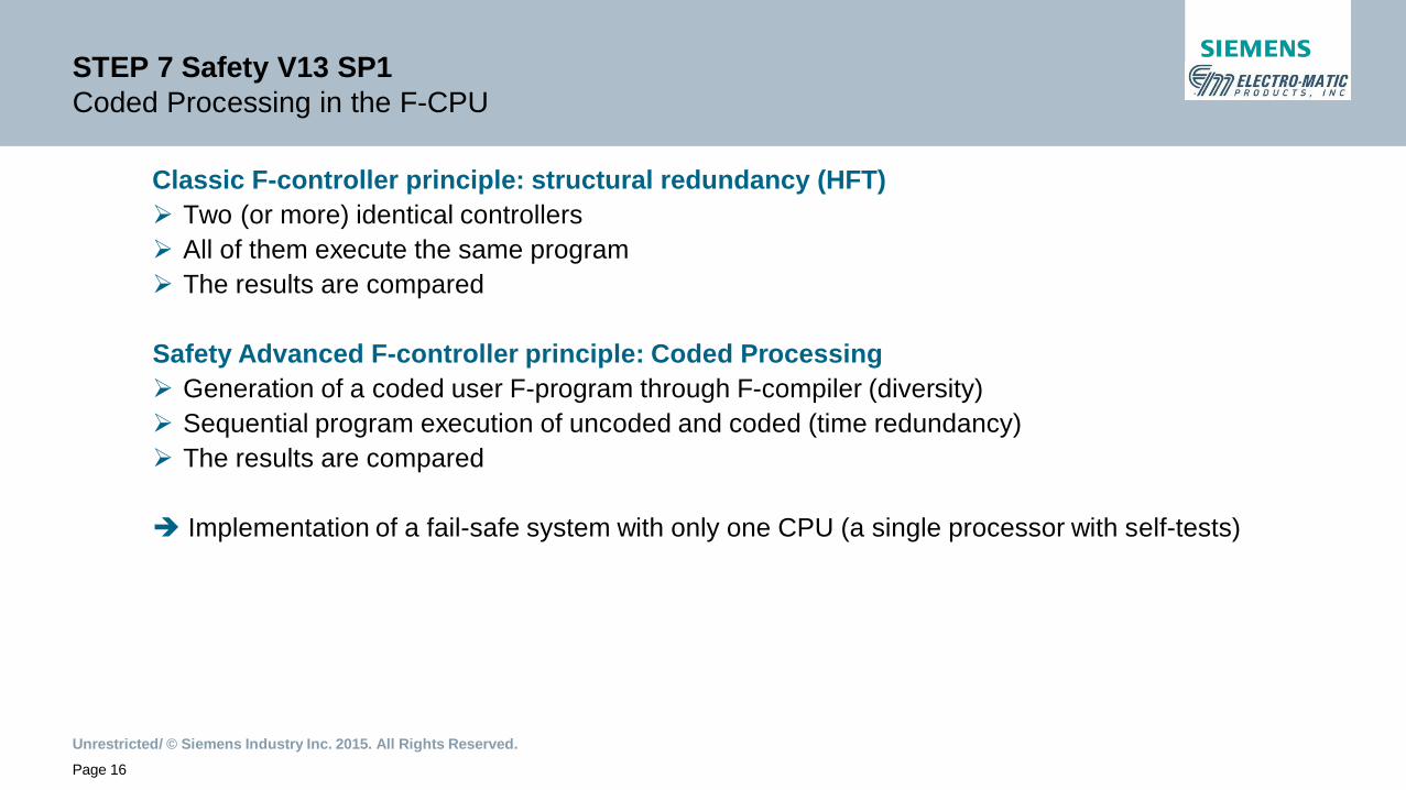
STEP 7 Safety V13 SP1Coded Processing in the F-CPU
Classic F-controller principle: structural redundancy (HFT)Ø Two (or more) identical controllersØ All of them execute the same programØ The results are compared
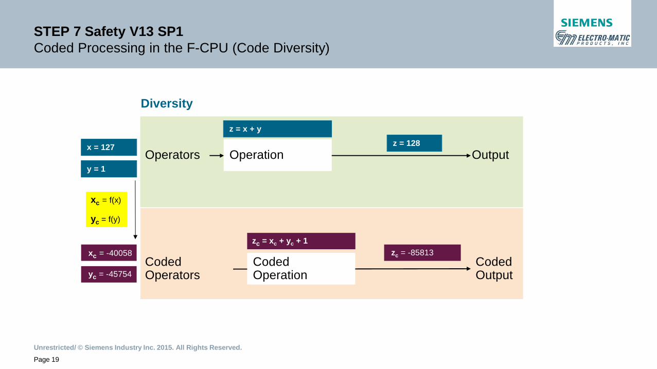
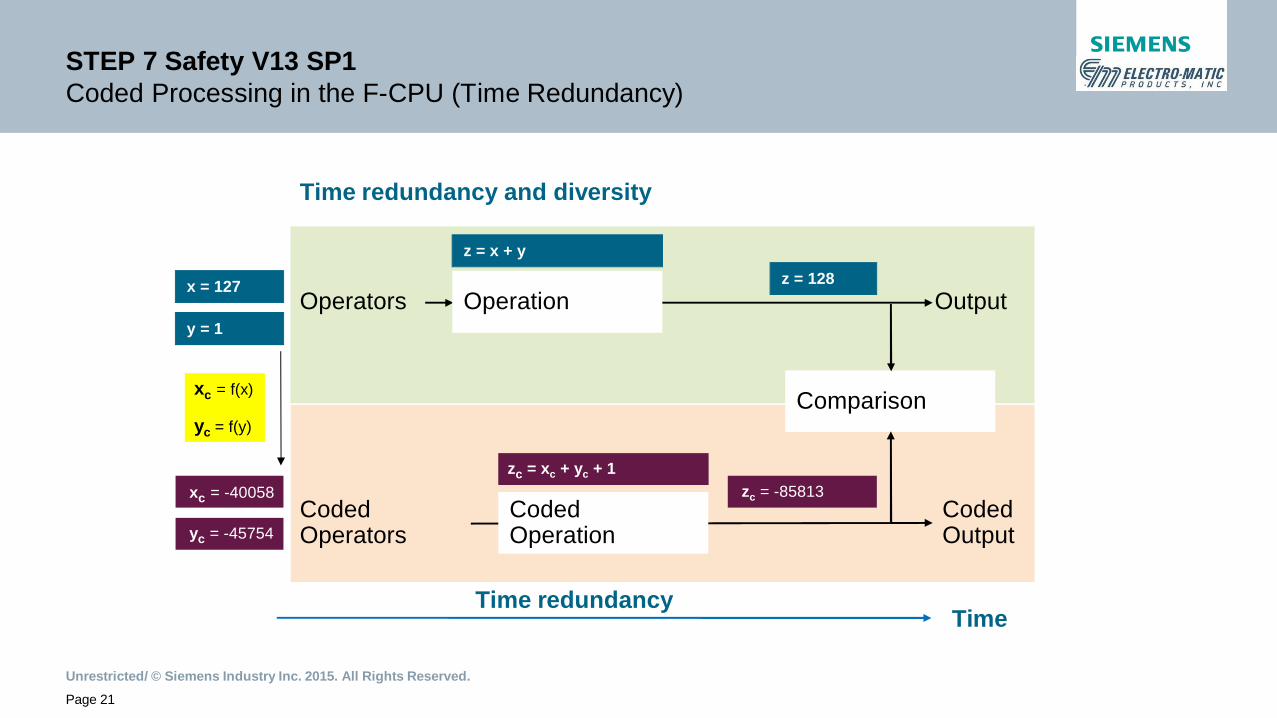
Safety Advanced F-controller principle: Coded ProcessingØ Generation of a coded user F-program through F-compiler (diversity)Ø Sequential program execution of uncoded and coded (time redundancy)Ø The results are compared
è Implementation of a fail-safe system with only one CPU (a single processor with self-tests)
Unrestricted/ © Siemens Industry Inc. 2015. All Rights Reserved.Page 17
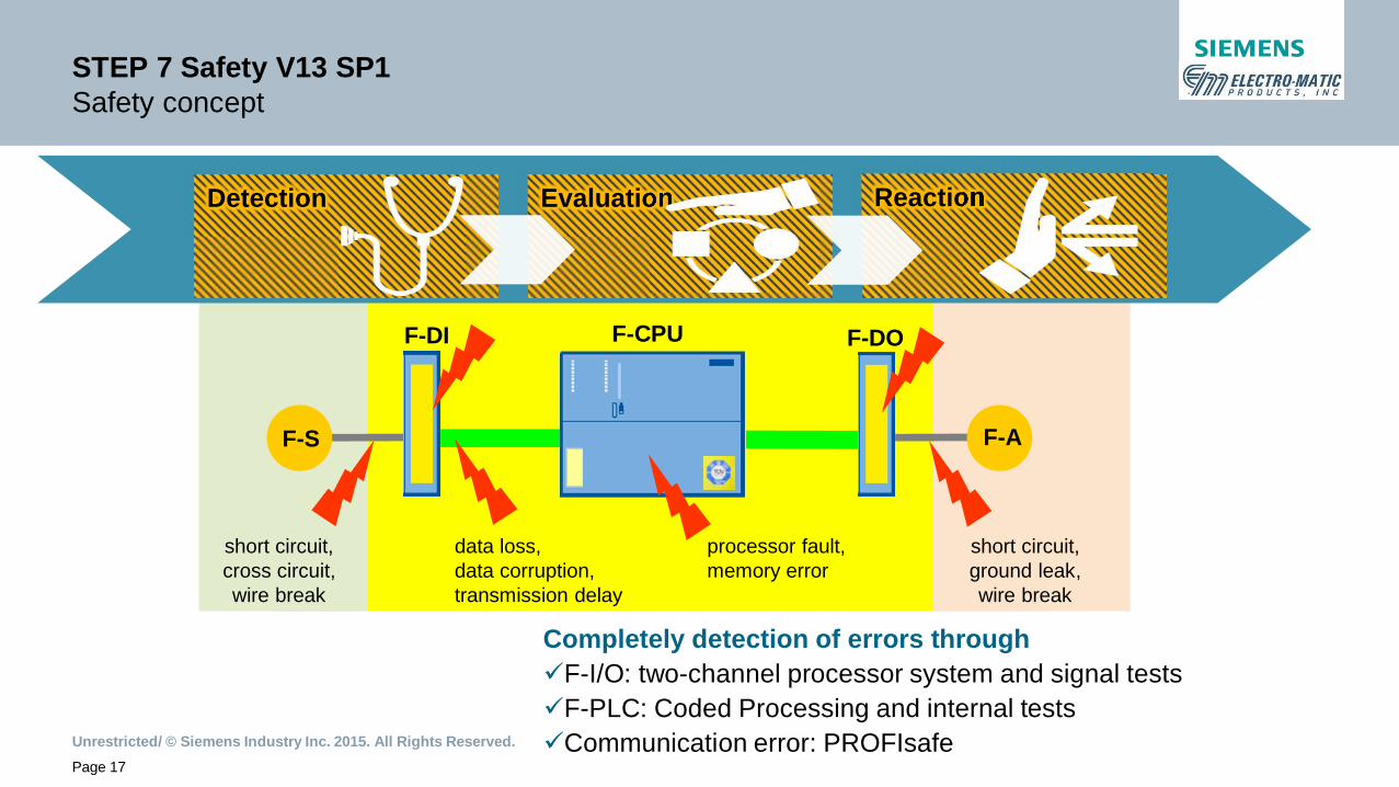
STEP 7 Safety V13 SP1Safety concept
F-CPU
F-S F-A
data loss,data corruption,transmission delay
short circuit,cross circuit,wire break
F-DI F-DO
short circuit,ground leak,wire break
processor fault,memory error
Completely detection of errors throughüF-I/O: two-channel processor system and signal testsüF-PLC: Coded Processing and internal testsüCommunication error: PROFIsafe
DetectionDetection EvaluationEvaluation ReactionReaction

Unrestricted/ © Siemens Industry Inc. 2015. All Rights Reserved.Page 18
STEP 7 Safety V13 SP1Coded Processing in the F-CPU (Standard Code)
OperationOperators Output
z = x + y
x = 127
y = 1
z = 128
Unrestricted/ © Siemens Industry Inc. 2015. All Rights Reserved.Page 19
STEP 7 Safety V13 SP1Coded Processing in the F-CPU (Code Diversity)
CodedOperation
CodedOperators
CodedOutput
xc = -40058
yc = -45754
zc = -85813
xc = f(x)
yc = f(y)
zc = xc + yc + 1
Diversity
OperationOperators Output
z = x + y
x = 127
y = 1
z = 128

Unrestricted/ © Siemens Industry Inc. 2015. All Rights Reserved.Page 20
STEP 7 Safety V13 SP1Coded Processing in the F-CPU (Time Redundancy)
Time redundancyTime
Time redundancy and diversity
CodedOperation
CodedOperators
CodedOutput
xc = -40058
yc = -45754
zc = -85813
xc = f(x)
yc = f(y)
zc = xc + yc + 1
OperationOperators Output
z = x + y
x = 127
y = 1
z = 128
Unrestricted/ © Siemens Industry Inc. 2015. All Rights Reserved.Page 21
Time redundancyTime
Time redundancy and diversity
CodedOperation
CodedOperators
CodedOutput
xc = -40058
yc = -45754
zc = -85813
xc = f(x)
yc = f(y)
zc = xc + yc + 1
OperationOperators Output
z = x + y
x = 127
y = 1
z = 128
STEP 7 Safety V13 SP1Coded Processing in the F-CPU (Time Redundancy)
Comparison
Unrestricted/ © Siemens Industry Inc. 2015. All Rights Reserved.Page 22
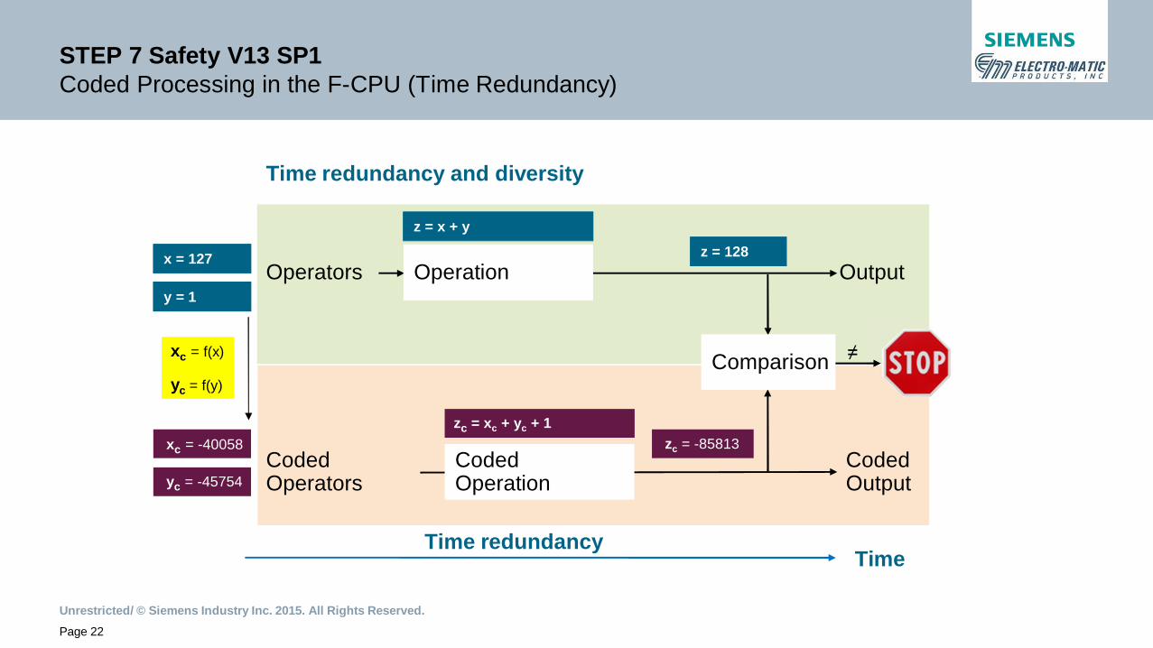
STEP 7 Safety V13 SP1Coded Processing in the F-CPU (Time Redundancy)
Time redundancyTime
Time redundancy and diversity
CodedOperation
CodedOperators
CodedOutput
xc = -40058
yc = -45754
zc = -85813
xc = f(x)
yc = f(y)
zc = xc + yc + 1
OperationOperators Output
z = x + y
x = 127
y = 1
z = 128
≠Comparison

Unrestricted/ © Siemens Industry Inc. 2015. All Rights Reserved.Page 23
STEP 7 Safety V13 SP1F-Runtime group
Execute F-user program
Execute coded F-user program
Read F-PII (F_CTRL_1)
Compare results
Write F-PIO (F_CTRL_2)
t
(F-CALL)
F-Runtime group
Unrestricted/ © Siemens Industry Inc. 2015. All Rights Reserved.Page 24
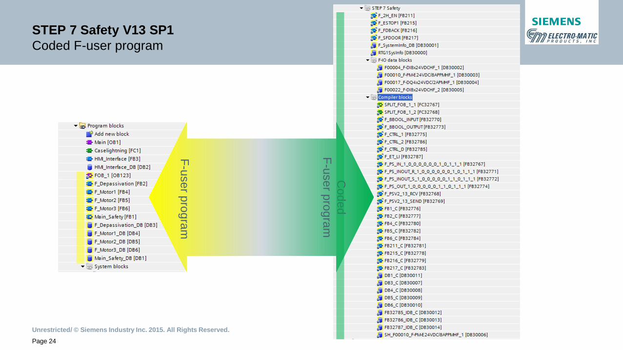
STEP 7 Safety V13 SP1Coded F-user program
F-userprogram
Coded
F-userprogram
Unrestricted/ © Siemens Industry Inc. 2015. All Rights Reserved.Page 25
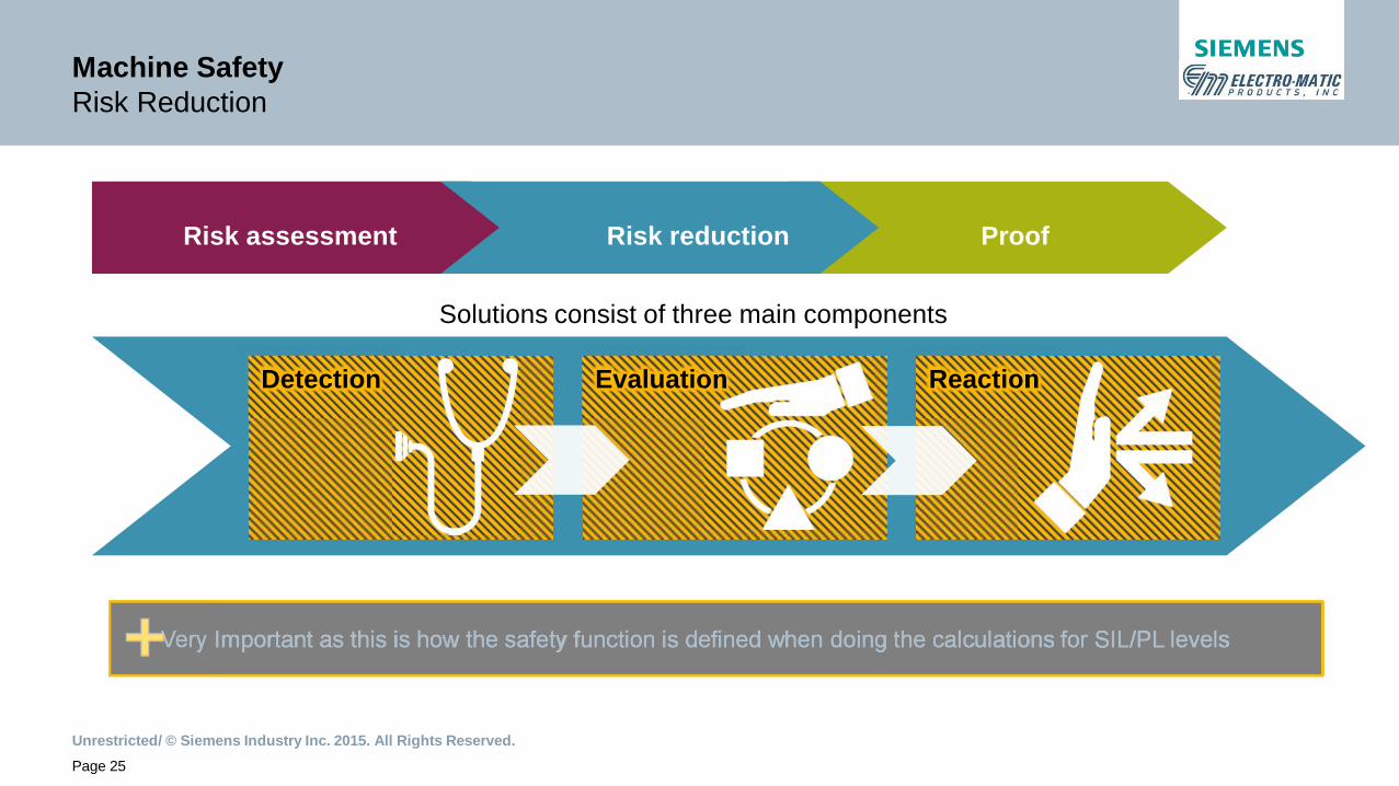
•Solutions consist of three main components
DetectionDetection EvaluationEvaluation ReactionReaction
Risk assessment Risk reduction Proof
Very Important as this is how the safety function is defined when doing the calculations for SIL/PL levelsVery Important as this is how the safety function is defined when doing the calculations for SIL/PL levels
Machine SafetyRisk Reduction

Unrestricted/ © Siemens Industry Inc. 2015. All Rights Reserved.Page 26
Input Devices
May Include Several or Just One of the Following:
(Depending Upon Safety Category Desired)
Mechanical Input Devices
• Emergency Stop (with or without enable or resets)
• Position Switch
• Interlock Switch
• AS-I Safe
DetectionDetection

Unrestricted/ © Siemens Industry Inc. 2015. All Rights Reserved.Page 27
Input Devices
May Include Several or Just One of the Following:
(Depending Upon Safety Category Desired)
Electronic Input Devices
• Solenoid Interlock Gate Switches
• Magnet or RFID Position Switches
• Light Grids / Area Laser Scanners
• Encoder Position Switches
• Safety Mats
DetectionDetection
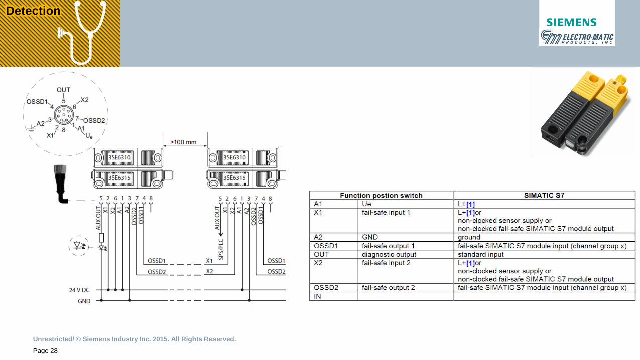
Unrestricted/ © Siemens Industry Inc. 2015. All Rights Reserved.Page 28
DetectionDetection

Unrestricted/ © Siemens Industry Inc. 2015. All Rights Reserved.Page 29
Safety Relay & Programmable Controllers
May Include One, Several, or a Combination of the Following:
(Depending Upon Safety Category Desired and Complexity)
• Safety Relays
• Programmable Safety Relays
• MSS (Modular Safety System)
EvaluationEvaluation

Unrestricted/ © Siemens Industry Inc. 2015. All Rights Reserved.Page 30
Programmable Controllers
May Include One, Several, or a Combination of the Following:
(Depending Upon Safety Category Desired and Complexity)
• S7-1200F
• ET200SP F
• S7-1500F
EvaluationEvaluation
Unrestricted/ © Siemens Industry Inc. 2015. All Rights Reserved.Page 31
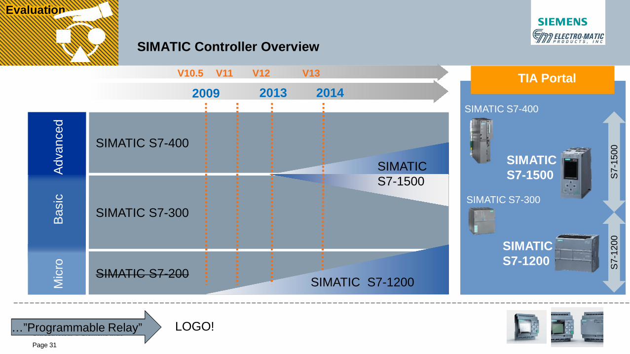
SIMATIC Controller Overview
SIMATIC S7-400
SIMATIC S7-300
SIMATICS7-1200
SIMATICS7-1500
TIA PortalB
asic
Adv
ance
dM
icro
2009 2013 2014
SIMATIC S7-400
SIMATIC S7-300
SIMATIC S7-200
SIMATICS7-1500
SIMATIC S7-1200
V10.5 V11 V12 V13
S7-
1500
S7-
1200
LOGO!…”Programmable Relay”
EvaluationEvaluation

Unrestricted/ © Siemens Industry Inc. 2015. All Rights Reserved.Page 32
Syst
emPe
rfor
man
ce
Application complexity
SIMATIC Safety IntegratedFail-safe Controllers - Overview
•S7-1500F for Advanced Control• Balance of control for machines or plants• Complex automation architectures requiring many HMI’s, drives, other field devices• Customized mass production control• Perfect for machine-to-machine controls required for an entire production process
S7-1200FCfor Basic Control• Perfect for stand-alone simple machine control• Material handling and packaging• Vertical form, fill and seal
ET 200SP F CPUsfor Distributed Control• Perfect for modular machines• Perfect for space constraints• Optimized for on-machine distributed
architectures• Available as an open controller
EvaluationEvaluation
Unrestricted/ © Siemens Industry Inc. 2015. All Rights Reserved.Page 33
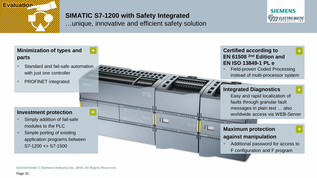
SIMATIC S7-1200 with Safety Integrated…unique, innovative and efficient safety solution
Minimization of types andparts§ Standard and fail-safe automation
with just one controller
§ PROFINET integrated
Investment protection§ Simply addition of fail-safe
modules to the PLC§ Simple porting of existing
application programs betweenS7-1200 <> S7-1500
Certified according toEN 61508 2nd Edition andEN ISO 13849-1 PL e§ Field-proven Coded Processing
instead of multi-processor system
Maximum protectionagainst manipulation§ Additional password for access to
F configuration and F program
Integrated Diagnostics• Easy and rapid localization of
faults through granular faultmessages in plain text … alsoworldwide access via WEB-Server
+ +
+
+
+
EvaluationEvaluation

Unrestricted/ © Siemens Industry Inc. 2015. All Rights Reserved.Page 34
Failsafe S7-1200-CPU’s(DC/DC/DC; DC/DC/Rly)
§ S7-1214FC§ S7-1215FC
Failsafe S7-1200 IO-Module§ SM 1226 F-DI 16 x 24VDC§ SM 1226 F-DQ 4 x 24VDC§ SM 1226 F-DQ 2 x Relay
STEP 7 Safety Advanced V13 SP1§ S7-300F/400F/1500F/1200F
STEP 7 Safety Basic V13 SP1§ S71200F
SIMATIC S7-1200 with Safety Integrated…Portfolio
EvaluationEvaluation

Unrestricted/ © Siemens Industry Inc. 2015. All Rights Reserved.Page 35
SIMATIC S7-1200 with Safety Integrated…Portfolio
CPU FeaturesCPU 1211C CPU 1212C CPU 1214FC CPU 1215FC CPU 1217C
Standard CPU DC/DC/DC, AC/DC/RLY, DC/DC/RLY DC/DC/DC
Failsafe CPU - - DC/DC/DC, DC/DC/RLY -
Work Memory, Integrated 30 KB 50 KB 75 / 100 KB 100 / 125 KB 125 KB
Load Memory, Integrated 1 MB 1 MB 4 MB 4 MB 4 MB
Retentive Memory, Integ. 10 KB 10 KB 10 KB 10 KB 10 KB
Bit Memory (M) 4 KB 4 KB 8 KB 8 KB 8 KB
Integ. Standard Digital I/O 6 Inputs / 4 Outputs 8 Inputs / 6 Outputs 14 Inputs / 10 Outputs 14 Inputs / 10 Outputs 14 Inputs / 10 Outputs*)
Integ. Standard Analog I/O 2 Inputs 2 Inputs / 2 Outputs
Process Image Size 1024 Bytes for Inputs / 1024 Bytes for Outputs
Signal Board Expansion 1 max.
Signal Module Expansion none 2 max. 8 max.
Max. Local I/O – Digital 14 82 284 284 284
Max. Local I/O – Analog 3 19 67 69 69
EvaluationEvaluation

Unrestricted/ © Siemens Industry Inc. 2015. All Rights Reserved.Page 36
Output Devices
May Include Several or Just One of the Following:
(Depending Upon Safety Category Required & Operation Desired)
• Safety Contactors (Positively Driven – Mirror Contacts)
• Safety Relays (Positively Driven – Mirror Contacts)
• Safety Motor Starters (3RM1 / ET200s)
• Safety VFDs (G120 / S120)
ReactionReaction

Unrestricted/ © Siemens Industry Inc. 2015. All Rights Reserved.Page 37
Siemens Safety IntegratedSafety Design Compliance - Safety Evaluation Tool
The Safety Evaluation tool• A free Internet-based tool for calculating safety functions
• ISO 13849-1 (successor standard of EN 954-1)• IEC 62061
• For documenting the results by a report• Offers easy, identical handling for both standards• Optimum support when using the Siemens products
Safety Evaluation Tool – Online Access
SET – Getting Started Document
SET Tutorial (YouTube)
Risk assessment Risk reduction Proof

Unrestricted/ © Siemens Industry Inc. 2015. All Rights Reserved.Page 38
Siemens Safety IntegratedMachine Safety Services
Risk AssessmentsPartners• GP Strategies• White Horse
Safety
Safety ValidationPartner• TÜV Rheinland
of North America
The Complete Safety Solution

Unrestricted/ © Siemens Industry Inc. 2015. All Rights Reserved.Page 39
Demo Unit Layout
Acknowledgement Button
Global ESTOP
RFID Safety Door Switch
Door Indicator Light
Local ESTOP
Zone 2 LED
Zone 1 LED
S7-1200 F Safety PLC
Safety Input Module
Safety Relay OutputModule #1
Safety Relay OutputModule #2
KTP400 Comfort Panel
LED Indicators

Unrestricted/ © Siemens Industry Inc. 2015. All Rights Reserved.Page 40
Thank you for your attention!
www.usa.siemens.com/safety
SIMATIC Safety IntegratedNow your power, to go full force ahead