Siemens AG: SIMATIC S7 MPI Direct
34
1 Siemens AG SIMATIC S7 MPI Direct Driver 1 System Configuration ....................................................................................................... 3 2 Selection of External Device ............................................................................................ 5 3 Example of Communication Setting ................................................................................. 6 4 Setup Items .................................................................................................................... 13 5 Cable Diagram ............................................................................................................... 18 6 Supported Device........................................................................................................... 31 7 Device Code and Address Code .................................................................................... 33 8 Error Messages .............................................................................................................. 34
Transcript of Siemens AG: SIMATIC S7 MPI Direct

1
Siemens AG
SIMATIC S7 MPI Direct Driver
1 System Configuration....................................................................................................... 3
2 Selection of External Device ............................................................................................ 5
3 Example of Communication Setting ................................................................................. 6
4 Setup Items .................................................................................................................... 13
5 Cable Diagram ............................................................................................................... 18
6 Supported Device........................................................................................................... 31
7 Device Code and Address Code.................................................................................... 33
8 Error Messages.............................................................................................................. 34

SIMATIC S7 MPI Direct Driver
GP-Pro EX Device/PLC Connection Manual 2
IntroductionThis manual describes how to connect the Display (GP3000 series) and the External Device (target PLC).
In this manual, the connection procedure will be described by following the below sections:
1 System ConfigurationThis section shows the types of External Devices which can be connected and SIO type.
"1 System Configuration" (page 3)
2 Selection of External DeviceSelect a model (series) of External Device to be connected and connection method.
"2 Selection of External Device" (page 5)
3 Example of Communication SettingsThis section shows setting examples for communicating between the Display and the External Device.
"3 Example of Communication Setting" (page 6)
4 Setup ItemsThis section describes communication setup items on the Display.Set communication settings of the Display with GP-Pro Ex or in off-line mode.
"4 Setup Items" (page 13)
5 Cable DiagramThis section shows cables and adapters for connecting the Display and the External Device.
"5 Cable Diagram" (page 18)
Operation

SIMATIC S7 MPI Direct Driver
GP-Pro EX Device/PLC Connection Manual 3
1 System Configuration
The system configuration in the case when the External Device of Siemens AG and the Display are connected is
shown.
Connection Configuration• 1:1 Connection
Series CPU ModuleConnection
PortSIO Type Setting Example Cable Diagram
SIMATICS7-200 Series
CPU214CPU215CPU216CPU221CPU222CPU224CPU226
Port 0/1 on the CPU unit
RS422/485 (2wire)
Setting Example 1 (page 6)
Cable Diagram 1 (page 18)
SIMATICS7-300 Series
CPU312IFMCPU313CPU314CPU314IFMCPU315CPU315-2 DPCPU316CPU316-2 DPCPU318-2
MPI port on the CPU unit
RS422/485 (2wire)
Setting Example 2 (page 9)
Cable Diagram 1 (page 18)
*1
Cable Diagram 2 (page 24)
*1 This cable diagram is only for the model which has the same port of PROFIBUS as MPI shown below.
SIMATICS7-400 Series
CPU412-1CPU412-2 DPCPU413-1CPU413-2 DPCPU414-1CPU414-2 DPCPU414-3 DPCPU416-1CPU416-2 DPCPU416-3 DPCPU417-4
MPI port on the CPU unit
RS422/485 (2wire)
Setting Example 2 (page 9)
Cable Diagram 1 (page 18)
*1
Cable Diagram 2 (page 24)
S7-300 Series 318-2 (6ES7 318 2AJ00)
S7-400 Series
412-1 (6ES7 412 1XF03), 412-2DP (6ES7 412 2XG00), 414-2DP (6ES7 414 2XG03), 414-3DP (6ES7 414-3XJ00), 416-2DP (6ES7 416 2XK02), 416-3DP (6ES7 416-3XL00), 417-4 (6ES7 417-4XL00)
Display External Device

SIMATIC S7 MPI Direct Driver
GP-Pro EX Device/PLC Connection Manual 4
• 1:n Connection
• n:1 Connection
• n:m Connection
• If the version of SIMANTIC S7 MPI Direct Driver is V1.00.04 or higher, you can mix the S7-300/400 Series and the S7-200 Series to use in one connection configuration.In case of V1.00.03 or lower, you cannot mix them.
• Only the S7-200/300/400 Series supports the n:1 connection.• Maximum unit number of the Display that can be connected to 1 unit of the External Device varies
depending on the type of the External Device. Please refer to the manual of each External Device for checking.
• Only the S7-200/300/400 Series supports the n:m connection.• For n:m connection, the unit number of Display and External Device is within the range which
satisfies the conditions below.•You can connect max 16 units of the External Device to 1 unit of the Display.•Maximum unit number of the Display that can be connected to 1 unit of the External Device
varies depending on the type of the External Device. Please refer to the manual of each External Device for checking.
Display External Device External Device
Max 16 units
n units
Display DisplayExternal Device
S7-200/300/400 Series
n units m units
Display Display
External Device
S7-200/300/400 Series
External Device
S7-200/300/400 Series

SIMATIC S7 MPI Direct Driver
GP-Pro EX Device/PLC Connection Manual 5
2 Selection of External Device
Select the External Device to be connected to the Display.
Setup Items Setup Description
Maker Select the maker of the External Device to be connected. Select "Siemens AG".
Driver
Select a model (series) of the External Device to be connected and connection method. Select "SIMATIC S7 MPI Direct".Check the External Device which can be connected in "SIMATIC S7 MPI Direct" in system configuration.
"1 System Configuration" (page 3)
Use System Area
Check this option when you synchronize the system data area of the Display and the device (memory) of the External Device. When synchronized, you can use the ladder program of the External Device to switch the display or display the window on the Display.
Cf. GP-Pro EX Reference Manual "Appendix 1.4 LS Area (only for direct access method)"
This can be also set with GP-Pro EX or in off-line mode of the Display.Cf. GP-Pro EX Reference Manual "System Area Setting, 6.13.6 Setting Guide
of [System Setting Window]"Cf. GP3000 Series User Manual "4.3.6 System Area Setting"
Port
Select the Display port to be connected to the External Device.
• When connect to S7-300/400 series, please use COM2.

SIMATIC S7 MPI Direct Driver
GP-Pro EX Device/PLC Connection Manual 6
3 Example of Communication Setting
Examples of communication settings of the Display and the External Device, recommended by Pro-face, are
shown.
3.1 Setting Example 1
Setting of GP-Pro EX
Communication Settings
To display the setting screen, select [Device/PLC Settings] from [System setting window] in workspace.

SIMATIC S7 MPI Direct Driver
GP-Pro EX Device/PLC Connection Manual 7
Device Setting
To display the setting screen, click ([Setting]) of External Device you want to set from [Device-Specific
Settings] of [Device/PLC Settings].
When [Allowable No. of Device/PLCs] is multiple, you can click from [Device-Specific Settings] of
[Device/PLC Settings] to add External Device which is available to set.
Settings of External DeviceUse the ladder software "STEP 7 Micro/WIN 32" to perform the communication settings for the S7-200 Series.
(1) Click [Communication] in the menu list. Check the connection among PLC (PORT0), the ladder cable (PC/
PPI Cable) and the PC, and double-click [Double-Click to Refresh].
(2) The [Search for Addresses] dialog box is displayed, and the software automatically scans the PLC. The dialog
box is closed when the connection is checked.
(3) Select [Type] from [PLC] on the menu bar.
(4) The [PLC Type] dialog box is displayed. Select according to the connected PLC type, and click [OK].
(5) Click [System Block] in the menu list, and set according to the port (Port0/Port1) to be actually connected to
the Display as below.
(6) When you finish setting, click [OK] and close the dialog box.
(7) Click the [Down load] button in the command menu.
(8) The [Download] dialog box is displayed. Check all items for [Program Block], [Data Block] and [System
Block], and click [OK].
Item Setup Description
PLC Address 2
Highest Address 31
Baud Rate 19.2k
Retry Count 2
Gap Update Factor 10

SIMATIC S7 MPI Direct Driver
GP-Pro EX Device/PLC Connection Manual 8
Restriction
Restriction for V1.00.03 or lower version of driver
• Since this protocol does not support the TimeMaster feature of S7-300/400 Series, time adjustment using this
feature is unavailable. If you use it, the communication of the main unit may break for a few seconds, or a
communication error may be displayed. Not using the Time Master feature is recommended.
• You cannot mix the S7-300/400 Series and the S7-200 Series to use in one connection configuration.
Restriction for V1.00.04 or higher version of driver
• Maximum speed is 187500bps.
When the speed is set to 500kbps or more in the project created by V1.00.03 or lower version, an error is
displayed in the main Display.
• When using more than one driver in a Display, you cannot use the DH-485 driver of Rockwell Automation,
Inc simultaneously.
In addition, you cannot use SIMANTIC S7 MPI Direct Driver in both COM1 and COM2.

SIMATIC S7 MPI Direct Driver
GP-Pro EX Device/PLC Connection Manual 9
3.2 Setting Example 2
Setting of GP-Pro EX
Communication Settings
To display the setting screen, select [Device/PLC Settings] from [System setting window] in workspace.
Device Setting
To display the setting screen, click ([Setting]) of External Device you want to set from [Device-Specific
Settings] of [Device/PLC Settings].
When [Allowable No. of Device/PLCs] is multiple, you can click from [Device-Specific Settings] of
[Device/PLC Settings] to add External Device which is available to set.

SIMATIC S7 MPI Direct Driver
GP-Pro EX Device/PLC Connection Manual 10
Settings of External DeviceUse the ladder software "SIMATIC Manager" to perform the communication settings for the S7-300/400 Series.
Set as below, following the steps.
(1) Click the icon of [New Project].
(2) Put the optional name and click [OK].
(3) From the menu bar, select [Insert], [Station], [1 SIMATIC 400 Station] in this order.
(4) "SIMATIC 400(1)" is created in the project. Double-click [Hardware] in the CPU.
(5) The "HW Config" screen is displayed. From the left tree, open [RACK- 400] from [SIMATIC 400], and
select the base unit of the using model, then drag & drop to the upper right window.
(6) Drag & drop the using power unit in the preset rack.
(7) Similarly, drag & drop the using CPU unit.
(8) Double-click the preset CPU unit "CPU xxx-xxx".
(9) The dialog box for the MPI port setting is displayed. Open [Properties].
(10)Check that "MPI(1)...187.5Kbps" is set as default. In addition, set [Address] which will be the destination
node number (PLC Address) you set in GP-Pro EX (the default value "2" is used this time). Select
"MPI(1)...187.5Kbps" and open [Properties].
(11)Click the [Network Settings] tab.
(12)You can change the transmission rate and the highest MPI address of the node No. in the dialog displayed
(select [187.5Kbps] for the transmission rate). When you change the highest MPI address of the node No. (set
to [31] this time), check the [Change] box to allow you to select the item. When you finish setting, click [OK].
(13)Click [OK] in the dialog box displayed in step 12.
(14)Click [OK] in the MPI port setting dialog box displayed in step 19.
(15)Check the connection between the PLC and the ladder software. Open [Set PG/PC Interface] from [Options]
in the menu bar.
(16)The [Set PG/PC Interface] dialog box is displayed. Click [Properites].
(17)Set [Transmission] to [187.5Kbps], and [Highest Node Address] to [31]. Click [OK].
Setup Items Setup Description
Speed 187500 bps
Destination Node No. 2
Source Node No. 1 (Option: Set the smaller value than Max Value of Node No.)
Max Value of Node No. 31
Supported DB Device DB1
• When using the S7-300 Series, select [2 SIMATIC 300 Station].

SIMATIC S7 MPI Direct Driver
GP-Pro EX Device/PLC Connection Manual 11
(18)Next click [Diagnostics].
(19)Click [Test] and [Read].
(20)If "OK" is displayed and other items than [0-0] of [Bus Nodes] are checked, the connection with the PLC is
established. Click [OK] and close the dialog box.
(21)Open [Blocks] in [S7 Program(2)] from [CPU xxx-xxx] of the project. Then, from the menu bar, click
[Insert], [S7 Block] and [4 Data Block] in this order.
(22)The [Properties - Data Black] dialog box is displayed. Click [OK].
(23)Open [DB1] created in [Block]. Right-click "INT" area of [Type], and select [ARRAY] from [Complex
Types].
Set the ARRAY range optionally. Here, enter "0.3000".
(24)When [Type] is changed to [ARRAY], one line will be added under it. Right-click the area, and select
[WORD] from [Elementary].
(25)Put [Name] optionally. You can use the displayed option as it is. In addition, there is no problem if you leave
[Initial value], [Comment] blank. Save and close the window.
(26)Open "Configure Network". Select "CPU 413-2 DP" and click the [Download] button.
(27)When the "PLC Download Selected Stations" is displayed, click "Yes" and continue to download.
(28)When you finish downloading, the dialog box is closed.
(29)Close the [Configure Network] window. When the [Network Save and Compile] dialog box is displayed,
click [Yes].
(30)When the [Save and Compile] dialog box is displayed, click [OK].
(31)Download [DB1] to the PLC. Select [DB1] and click the [Download] button.
(32)When the [Download] dialog box is displayed, click [Yes] and continue to download.
(33)When the download is completed, no message such as error is displayed. If nothing is displayed, the PLC
setting is completed.
Restriction
Restriction for V1.00.03 or lower version of driver
• Since this protocol does not support the TimeMaster feature of S7-300/400 Series, time adjustment using this
feature is unavailable. If you use it, the communication of the main unit may break for a few seconds, or a
communication error may be displayed. Not using the Time Master feature is recommended.
• You cannot mix the S7-300/400 Series and the S7-200 Series to use in one connection configuration.
Restriction for V1.00.04 or higher version of driver
• Maximum speed is 187500bps.
When the speed is set to 500kbps or more in the project created by V1.00.03 or lower version, an error is
displayed in the main Display.
• When using more than one driver in a Display, you cannot use the DH-485 driver of Rockwell Automation,
Inc simultaneously.

SIMATIC S7 MPI Direct Driver
GP-Pro EX Device/PLC Connection Manual 12
• In addition, you cannot use SIMANTIC S7 MPI Direct Driver in both COM1 and COM2.

SIMATIC S7 MPI Direct Driver
GP-Pro EX Device/PLC Connection Manual 13
4 Setup Items
Set communication settings of the Display with GP-Pro EX or in off-line mode of the Display.
The setting of each parameter must be identical to that of External Device.
"3 Example of Communication Setting" (page 6)
4.1 Setup Items in GP-Pro EX
Communication SettingsTo display the setting screen, select [Device/PLC Settings] from [System setting window] in workspace.
Setup Items Setup Description
SIO Type Select the SIO type to communicate with the External Device.
Speed
Select speed between the External Device and the Display.
• When connecting to the COM1 port of the Display, up to 19200bps is supported.When connecting to the COM2 port of the Display, 187500bps is supported.
Data Length Select data length.
Parity Select how to check parity.
Stop Bit Select stop bit length.
Flow Control Select the communication control method to prevent overflow of transmission and reception data.

SIMATIC S7 MPI Direct Driver
GP-Pro EX Device/PLC Connection Manual 14
Device SettingTo display the setting screen, click ([Setting]) of the External Device you want to set from [Device-Specific
Settings] of [Device/PLC Settings].
When [Allowable No. of Device/PLCs] is multiple, you can click from [Device-Specific Settings] of
[Device/PLC Settings] to add the External Device which is available to set.
Timeout Use an integer from 1 to 127 to enter the time (s) for which the Display waits for the response from the External Device.
Retry In case of no response from the External Device, use an integer from 0 to 255 to enter how many times the Display retransmits the command.
Wait To Send Use an integer from 0 to 255 to enter standby time (ms) for the Display from receiving packets to transmitting next commands.
Local Node Use an integer from 0 to 126 to enter the local node No. of the Display.
Highest Node Number Select any of [15], [31], [63] and [126] for the highest value of the node No.
Clock Synchronization on MPI (as Slave)
Selecting (check mark) this checkbox enables the Time Master settings.When the Time Master is enabled, the Time Interval set via the External Device overwrites the Master External Device’s Display time data. Use the External Device’s ladder software to perform master external device settings. Select the [H/W Configuration] → CPU menu’s [Diagnostics Properties] → Diagnostics/Clock feature. For details, refer to your external device’s Operation Manual
Setup Items Setup Description
PLC Type
For the type of External Device to communicate, select any of [S-7-300/400 Series [English Device Names]], [S-7-300/400 Series [German Device Names]], [S-7-200 Series [English Device Names]] and [S-7-200 Series [German Device Names]].Select [English Device Name] or [German Device Name] depending on whether the device name is described in English or German.
Target NodeUse an integer from 0 to 126 to enter the node No. of the External Device. Be sure to set the node No. within the range which does not exceed the value set in [Highest Node Number] of [Communication Settings].
Setup Items Setup Description

SIMATIC S7 MPI Direct Driver
GP-Pro EX Device/PLC Connection Manual 15
4.2 Setup Items in Off-Line Mode
Communication SettingsTo display the setting screen, touch [Device/PLC Settings] from [Peripheral Settings] in off-line mode. Touch the
External Device you want to set from the displayed list, and touch [Communication Settings].
(Page 1/2)
• Please refer to GP3000 Series User Manual for more information on how to enter off-line mode or about operation.Cf. GP3000 Series User Manual "Chapter 4 Setting"
Setup Items Setup Description
SIO Type Select the SIO type to communicate with the External Device.
Speed Select speed between the External Device and the Display.
Data Length Select data length.
Parity Select how to check parity.
Stop Bit Select stop bit length.
Flow Control Select the communication control method to prevent overflow of transmission and reception data.
Timeout Use an integer from 1 to 127 to enter the time (s) for which the Display waits for the response from the External Device.
Retry In case of no response from the External Device, use an integer from 0 to 255 to enter how many times the Display retransmits the command.
Wait To Send Use an integer from 0 to 255 to enter standby time (ms) for the Display from receiving packets to transmitting next commands.

SIMATIC S7 MPI Direct Driver
GP-Pro EX Device/PLC Connection Manual 16
(Page 2/2)
Setup Items Setup Description
Local Node Use an integer from 0 to 126 to enter the local node No. of the Display.
Highest Node Select any of [15], [31], [63] and [126] for the highest value of the node No.
Clock Synchronization
Selecting (check mark) this checkbox enables the Time Master settings.When the Time Master is enabled, the Time Interval set via the External Device overwrites the Master External Device’s Display time data. Use the External Device’s ladder software to perform master external device settings. Select the [H/W Configuration] → CPU menu’s [Diagnostics Properties] → Diagnostics/Clock feature. For details, refer to your external device’s Operation Manual

SIMATIC S7 MPI Direct Driver
GP-Pro EX Device/PLC Connection Manual 17
Device SettingTo display the setting screen, touch [Device/PLC Settings] from [Peripheral Settings]. Touch the External Device
you want to set from the displayed list, and touch [Device].
Setup Items Setup Description
Device/PLC Name Select the External Device for device setting. Device name is a title of External Device set with GP-Pro EX.(Initial value [PLC1])
SeriesDisplays the PLC type selected in [Device Setting] of GP-Pro EX.You cannot change the PLC type in [Device Setting] in off-line mode.
"4.1 Setup Items in GP-Pro EX Device Setting" (page 14)
Target NodeUse an integer from 0 to 126 to enter the node No. of the External Device. Be sure to set the node No. within the range which does not exceed the value set in [Highest Node] of [Communication Settings].

SIMATIC S7 MPI Direct Driver
GP-Pro EX Device/PLC Connection Manual 18
5 Cable Diagram
The cable diagram shown below may be different from the cable diagram recommended by Siemens AG. Please
be assured there is no operational problem in applying the cable diagram shown in this manual.
• The FG pin of the External Device body must be D-class grounded. Please refer to the manual of the External
Device for more details.
• SG and FG are connected inside the Display. When connecting SG to the External Device, design the system
not to form short-circuit loop.
Cable Diagram 1
Display (Connection Port)
Cable Remarks
GP*1 (COM1)*2
AGP-3302 (COM2)
*1 All GP models except AGP-3302
*2 You can use the COM1 port only when connecting the S7-200 Series.
A Your own cable
The cable length must be 50m or less in one segment.
B
COM port conversion adapter (for COM1)by Pro-face
CA3-ADPCOM-01+
Connector terminal block conversion adapter by Pro-face
CA3-ADPTRM-01+
Your own cable
GP*1 (COM2)
C
Online adapter by Pro-faceCA4-ADPONL-01
+Your own cable
D
Online adapter by Pro-faceCA4-ADPONL-01
+Connector terminal block conversion adapter
by Pro-faceCA3-ADPTRM-01
+Your own cable

SIMATIC S7 MPI Direct Driver
GP-Pro EX Device/PLC Connection Manual 19
A) When using your own cable
• 1:1 Connection
• 1:n Connection
SDA
RDA
RDB
SDB
3
7
1
2
SHIELD
SG5
B
A
3
8
9
8
4
SG
ERB
CSA
CSB
ERA
FG
5
6
Display
Terminationresistance
D-sub 9 pin (socket)
Pin Signalname
Shell
Shield
External Device
D-sub 9 pin (plug)
Pin Signalname
Terminationresistance
SDA
RDA
RDB
SDB
3
7
1
2
SHIELD
SG5
B
A
3
8
SHIELD
SG5
B
A
3
8
9
8
4
SG
ERB
CSA
CSB
ERA
FG
5
6
Display
Terminationresistance
D-sub 9 pin (socket)
Pin Signalname
Shell
Shield
External Device
D-sub 9 pin (plug)Terminationresistance
Pin Signalname
Shield
External Device
D-sub 9 pin (plug)
Pin Signalname

SIMATIC S7 MPI Direct Driver
GP-Pro EX Device/PLC Connection Manual 20
• n:1 Connection
SDA
RDA
RDB
SDB
3
7
1
2
9
8
4
SG
ERB
CSA
CSB
ERA
FG
5
6
SDA
RDA
RDB
SDB
3
7
1
2
SHIELD
SG5
B
A
3
8
9
8
4
SG
ERB
CSA
CSB
ERA
FG
5
6
Display
Terminationresistance
D-sub 9 pin (socket)
Pin Signalname
Shell
Shield D-sub 9 pin (socket)
Terminationresistance
Pin Signalname
Shield
External Device
D-sub 9 pin (plug)
Pin Signalname
Shell
Display

SIMATIC S7 MPI Direct Driver
GP-Pro EX Device/PLC Connection Manual 21
B) When using the COM port conversion adapter (for COM1) (CA3-ADPCOM-01), the connector terminal block
conversion adapter (CA3-ADPTRM-01) by Pro-face and your own cable
• 1:1 Connection
• 1:n Connection
• n:1 Connection
SDA
RDA
RDB
SG
FG
SDB
SHIELD
SG5
B
A
3
8
CA3-ADPCOM-01
CA3-ADPTRM-01
Display
Terminationresistance
Terminal
block
Signal name
Shield
External Device
D-sub 9 pin (plug)
Pin Signalname
Terminationresistance
Your own cable
SHIELD
SG5
B
A
3
8
SDA
RDA
RDB
SG
FG
SDBCA3-ADPCOM-01
CA3-ADPTRM-01
SHIELD
SG5
B
A
3
8
Display
Terminationresistance
Terminal
block
Signal name
Shield
External Device
D-sub 9 pin (plug)
PinSignalname
Shield
External Device
D-sub 9 pin (plug)
PinSignalname
Terminationresistance
Your own cable
CA3-ADPCOM-01
CA3-ADPTRM-01
SDA
RDA
RDB
SG
FG
SDB
SDA
RDA
RDB
SG
FG
SDB
SHIELD
SG5
B
A
3
8
CA3-ADPCOM-01
CA3-ADPTRM-01
Display
Terminationresistance
Terminal
block
Signal name
Shield
Terminal
block
Signal name
Shield
Display
External Device
D-sub 9 pin (plug)TerminationresistancePin Signal
name
Your own cable

SIMATIC S7 MPI Direct Driver
GP-Pro EX Device/PLC Connection Manual 22
C) When using the online adapter (CA4-ADPONL-01) by Pro-face and your own cable
• 1:1 Connection
• 1:n Connection
• n:1 Connection
• Wrong connection could lead to malfunction or breakdown of the CPU.Please ensure that the side (Display Device / PLC) of the cable matches the port of connected device.
• When connecting more than 1 Display, use the online adapter for only one Display.
RDB
SG
RDA
SDA
SDB
FG
7CA4-ADPONL-01
2
3
8
5
SHIELD
SG5
B
A
3
8
Display
Terminationresistance
Shield
External Device
D-sub 9 pin (plug)
Pin Signalname
Terminationresistance
Your own cable
Pin Signalname
Shell
D-sub 9 pin (plug)
SG
FG
5
SHIELD
SG5
B
A
3
8
SHIELD
SG5
B
A
3
8RDB
RDA
SDA
SDB
7CA4-ADPONL-01
2
3
8
Display
D-sub 9 pin (plug)
Pin Signalname
Shell
Shield
External Device
D-sub 9 pin (plug)Terminationresistance
Your own cable
Pin Signalname
Shield
External Device
D-sub 9 pin (plug)
Terminationresistance
Pin Signalname
SHIELD
SG5
B
A
3
8
SG
FG
5
RDB
RDA
SDA
SDB
7
2
3
8
CA4-ADPONL-01
SG
FG
5
RDB
RDA
SDA
SDB
7
2
3
8
Display
D-sub 9 pin (plug)
Pin Signalname
Shell
Shield
External Device
D-sub 9 pin (plug)Terminationresistance
Your own cable
Pin Signalname
Terminationresistance
D-sub 9 pin (plug)
Pin Signalname
Shell
Shield
Display

SIMATIC S7 MPI Direct Driver
GP-Pro EX Device/PLC Connection Manual 23
D) When using the online adapter (CA4-ADPONL-01), the connector terminal block conversion adapter (CA3-
ADPTRM-01) by Pro-face and your own cable
• 1:1 Connection
• 1:n Connection
• n:1 Connection
• Wrong connection could lead to malfunction or breakdown of the CPU.Please ensure that the side (Display Device / PLC) of the cable matches the port of connected device.
• When connecting more than 1 Display, use the online adapter for only one Display.
SDA
RDA
RDB
SG
FG
SDB
SHIELD
SG5
B
A
3
8
CA4-ADPONL-01
CA3-ADPTRM-01
Display
Signalname
Shield
External Device
D-sub 9 pin (plug)
Terminationresistance
Your own cable
Pin Signalname
Terminationresistance
Terminal
block
SHIELD
SG5
B
A
3
8
SDA
RDA
RDB
SG
FG
SDBCA4-ADPONL-01
CA3-ADPTRM-01
SHIELD
SG5
B
A
3
8
Display
Signalname
Shield
External Device
D-sub 9 pin (plug)
Terminationresistance
Your own cable
Pin Signalname
Shield
Terminationresistance
Terminal
block
External Device
D-sub 9 pin (plug)
Pin Signalname
CA4-ADPONL-01
CA3-ADPTRM-01
SDA
RDA
RDB
SG
FG
SDB
SDA
RDA
RDB
SG
FG
SDB
SHIELD
SG5
B
A
3
8
CA3-ADPTRM-01
Display
Shield
External Device
D-sub 9 pin (plug)
Terminationresistance
Your own cable
Pin Signalname
ShieldTerminationresistance
Terminal
block
Signalname
Terminal
block
Signalname
Display
SIMATIC S7 MPI Direct Driver
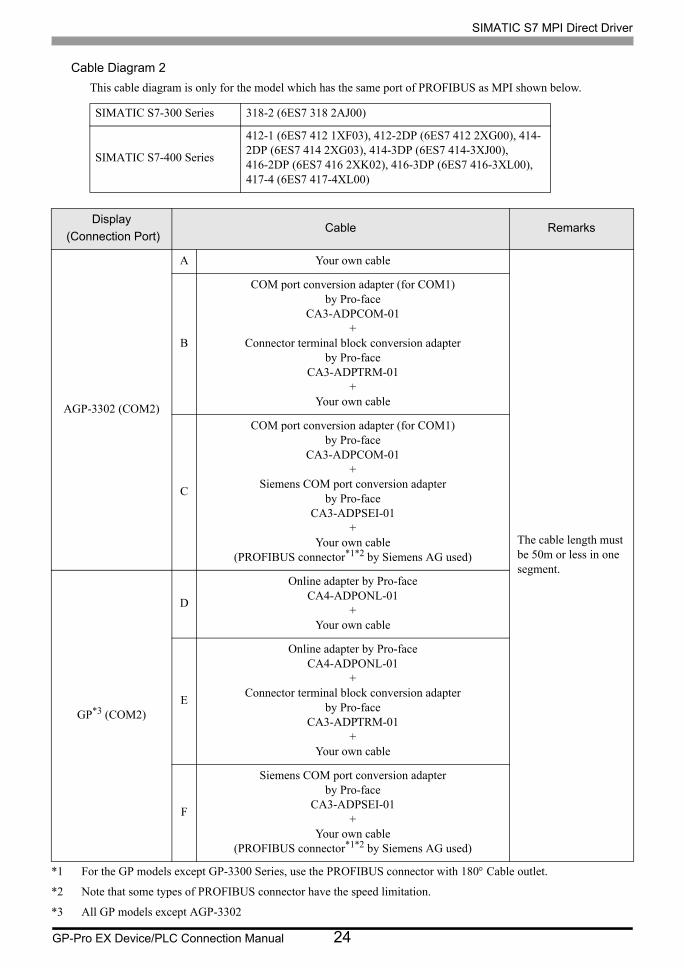
GP-Pro EX Device/PLC Connection Manual 24
Cable Diagram 2This cable diagram is only for the model which has the same port of PROFIBUS as MPI shown below.
SIMATIC S7-300 Series 318-2 (6ES7 318 2AJ00)
SIMATIC S7-400 Series
412-1 (6ES7 412 1XF03), 412-2DP (6ES7 412 2XG00), 414-2DP (6ES7 414 2XG03), 414-3DP (6ES7 414-3XJ00), 416-2DP (6ES7 416 2XK02), 416-3DP (6ES7 416-3XL00), 417-4 (6ES7 417-4XL00)
Display (Connection Port)
Cable Remarks
AGP-3302 (COM2)
A Your own cable
The cable length must be 50m or less in one segment.
B
COM port conversion adapter (for COM1)by Pro-face
CA3-ADPCOM-01+
Connector terminal block conversion adapter by Pro-face
CA3-ADPTRM-01+
Your own cable
C
COM port conversion adapter (for COM1)by Pro-face
CA3-ADPCOM-01+
Siemens COM port conversion adapter by Pro-face
CA3-ADPSEI-01+
Your own cable(PROFIBUS connector*1*2 by Siemens AG used)
*1 For the GP models except GP-3300 Series, use the PROFIBUS connector with 180° Cable outlet.
*2 Note that some types of PROFIBUS connector have the speed limitation.
GP*3 (COM2)
*3 All GP models except AGP-3302
D
Online adapter by Pro-faceCA4-ADPONL-01
+Your own cable
E
Online adapter by Pro-faceCA4-ADPONL-01
+Connector terminal block conversion adapter
by Pro-faceCA3-ADPTRM-01
+Your own cable
F
Siemens COM port conversion adapter by Pro-face
CA3-ADPSEI-01+
Your own cable(PROFIBUS connector*1*2 by Siemens AG used)

SIMATIC S7 MPI Direct Driver
GP-Pro EX Device/PLC Connection Manual 25
A) When using your own cable
• 1:1 Connection
• 1:n Connection
• n:1 Connection
SDA
RDA
RDB
SDB
3
7
1
2
9
8
4
SG
ERB
CSA
CSB
ERA
FG
5
6
SHIELD
A
B3
8
Display
D-sub 9 pin (socket)
Pin Signalname
Shell
Shield
External Device
D-sub 9 pin (plug)
TerminationresistancePin Signal
name
Terminationresistance
SDA
RDA
RDB
SDB
3
7
1
2
9
8
4
SG
ERB
CSA
CSB
ERA
FG
5
6
SHIELD
A
B3
8
SHIELD
A
B3
8
Display
D-sub 9 pin (socket)
Pin Signalname
Shell
Shield
External Device
D-sub 9 pin (plug)TerminationresistancePin Signal
name
Shield
Terminationresistance
External Device
D-sub 9 pin (plug)
Pin Signalname
SDA
RDA
RDB
SDB
3
7
1
2
9
8
4
SG
ERB
CSA
CSB
ERA
FG
5
6
SDA
RDA
RDB
SDB
3
7
1
2
9
8
4
SG
ERB
CSA
CSB
ERA
FG
5
6
SHIELD
A
B3
8
Display
D-sub 9 pin (socket)
Pin Signalname
Shell
Shield D-sub 9 pin (socket)
Terminationresistance
Pin Signalname
Shield
External Device
D-sub 9 pin (plug)
Terminationresistance
Shell
Display
Pin Signalname

SIMATIC S7 MPI Direct Driver
GP-Pro EX Device/PLC Connection Manual 26
B) When using the COM port conversion adapter (for COM1) (CA3-ADPCOM-01), the connector terminal block
conversion adapter (CA3-ADPTRM-01) by Pro-face and your own cable
• 1:1 Connection
• 1:n Connection
• n:1 Connection
FG
SDA
RDA
RDB
SDBCA3-ADPCOM-01
CA3-ADPTRM-01SHIELD
A
B3
8
Display
Signalname
Shield
External Device
D-sub 9 pin (plug)Terminationresistance
Your own cable
Pin Signalname
Terminationresistance
Terminal
block
FG
SDA
RDA
RDB
SDBCA3-ADPCOM-01
CA3-ADPTRM-01SHIELD
B
A
3
8
SHIELD
A
B3
8
Display
Signalname
Shield
External Device
D-sub 9 pin (plug)
Terminationresistance
Your own cable
Pin Signalname
ShieldTerminationresistance
Terminal
block
External Device
D-sub 9 pin (plug)
Pin Signalname
CA3-ADPCOM-01
CA3-ADPTRM-01
SDA
RDA
RDB
SDB
FG FG
SDA
RDA
RDB
SDB
SHIELD
A
B3
8
CA3-ADPCOM-01
CA3-ADPTRM-01
Display
Signalname
Shield
External Device
D-sub 9 pin (plug)
Terminationresistance
Your own cable
Pin Signalname
ShieldTerminationresistance
Terminal
block
Signalname
Terminal
block
Display

SIMATIC S7 MPI Direct Driver
GP-Pro EX Device/PLC Connection Manual 27
C) When using the COM port conversion adapter (for COM1) (CA3-ADPCOM-01), the Siemens COM port
conversion adapter by Pro-face (CA3-ADPSEI-01) by Pro-face and your own cable (PROFIBUS connector by
Siemens AG used)
• 1:1 Connection
• 1:n Connection
• n:1 Connection
SHIELD
B
A
3
8
SHIELD
A
B3
8
CA3-ADPSEI-01
CA3-ADPCOM-01
PROFIBUS connector
Termination resistance: ON
D-sub 9 pin (plug)
PROFIBUS connector
Termination resistance: ON
D-sub 9 pin (plug)
Display Pin Signalname
Your own cable
Shield
Pin Signalname
SHIELD
B
A
3
8
SHIELD
A
B3
8
SHIELD
A
B3
8
CA3-ADPSEI-01
CA3-ADPCOM-01
PROFIBUS connector
Termination resistance: ON
D-sub 9 pin (plug)
External Device
PROFIBUS connector
Termination resistance: OFF
D-sub 9 pin (plug)
Display Pin Signalname
Your own cable
Shield
Pin Signalname
Shield
External Device
PROFIBUS connector
Termination resistance: ON
D-sub 9 pin (plug)
Pin Signalname
SHIELD
B
A
3
8
SHIELD
A
B3
8
SHIELD
A
B3
8
CA3-ADPSEI-01
CA3-ADPCOM-01
CA3-ADPSEI-01
CA3-ADPCOM-01
PROFIBUS connector
Termination resistance: ON
D-sub 9 pin (plug)
PROFIBUS connector
Termination resistance: OFF
D-sub 9 pin (plug)
Display Pin Signalname
Your own cable
Shield
Pin Signalname
Shield
External Device
PROFIBUS connector
Termination resistance: ON
D-sub 9 pin (plug)
Pin Signalname
Display

SIMATIC S7 MPI Direct Driver
GP-Pro EX Device/PLC Connection Manual 28
D) When using the online adapter (CA4-ADPONL-01) by Pro-face and your own cable
• 1:1 Connection
• 1:n Connection
• n:1 Connection
• Wrong connection could lead to malfunction or breakdown of the CPU.Please ensure that the side (Display Device / PLC) of the cable matches the port of connected device.
• When connecting more than 1 Display, use the online adapter for only one Display.
CA4-ADPONL-01
FG
RDB
RDA
SDA
SDB
7
2
3
8
SHIELD
A
B3
8
Display
D-sub 9 pin (plug)
Pin Signalname
Shell
Shield
External Device
D-sub 9 pin (plug)Terminationresistance
Your own cable
Pin Signalname
Terminationresistance
SHIELD
A
B3
8
FG
RDB
RDA
SDA
SDB
7
2
3
8
CA4-ADPONL-01
SHIELD
A
B3
8
Display
D-sub 9 pin (plug)
Pin Signalname
Shell
Shield
External Device
D-sub 9 pin (plug)
Terminationresistance
Your own cable
Pin Signalname
Shield
Terminationresistance External Device
D-sub 9 pin (plug)
Pin Signalname
SHIELD
A
B3
8CA4-ADPONL-01
FG
RDB
RDA
SDA
SDB
7
2
3
8
FG
RDB
RDA
SDA
SDB
7
2
3
8
Display
D-sub 9 pin (plug)
Pin Signalname
Shell
Shield
External Device
D-sub 9 pin (plug)
Terminationresistance
Your own cable
Pin Signalname
ShieldTerminationresistance
D-sub 9 pin (plug)
Pin Signalname
Shell
Display

SIMATIC S7 MPI Direct Driver
GP-Pro EX Device/PLC Connection Manual 29
E) When using the online adapter (CA4-ADPONL-01), the connector terminal block conversion adapter (CA3-
ADPTRM-01) by Pro-face and your own cable
• 1:1 Connection
• 1:n Connection
• n:1 Connection
• Wrong connection could lead to malfunction or breakdown of the CPU.Please ensure that the side (Display Device / PLC) of the cable matches the port of connected device.
• When connecting more than 1 Display, use the online adapter for only one Display.
FG
SDA
RDA
RDB
SDBCA4-ADPONL-01
CA3-ADPTRM-01SHIELD
A
B3
8
Display
Signalname
Shield
External Device
D-sub 9 pin (plug)
Terminationresistance
Your own cable
Pin Signalname
Terminationresistance
Terminal
block
FG
SDA
RDA
RDB
SDBCA4-ADPONL-01
CA3-ADPTRM-01SHIELD
B
A
3
8
SHIELD
A
B3
8
Display
Signalname
Shield
External Device
D-sub 9 pin (plug)
Terminationresistance
Your own cable
Pin Signalname
Shield
Terminationresistance
Terminal
block
External Device
D-sub 9 pin (plug)
Pin Signalname
CA4-ADPONL-01
CA3-ADPTRM-01
SDA
RDA
RDB
SDB
FG FG
SDA
RDA
RDB
SDB
SHIELD
A
B3
8
CA3-ADPTRM-01
Display
Signalname
Shield
External Device
D-sub 9 pin (plug)
Terminationresistance
Your own cable
Pin Signalname
Terminationresistance
Terminal
block
Signalname
Terminal
block Shield
Display

SIMATIC S7 MPI Direct Driver
GP-Pro EX Device/PLC Connection Manual 30
F) When using the Siemens COM port conversion adapter by Pro-face and your own cable (PROFIBUS
connector by Siemens AG used)
• 1:1 Connection
• 1:n Connection
• n:1 Connection
• Wrong connection could lead to malfunction or breakdown of the CPU.Please ensure that the side (Display Device / PLC) of the cable matches the port of connected device.
• When connecting more than 1 Display, use the online adapter for only one Display.
SHIELD
B
A
3
8
SHIELD
A
B3
8
CA3-ADPSEI-01
PROFIBUS connector
Termination resistance: ON
D-sub 9 pin (plug)
External Device
PROFIBUS connector
Termination resistance: ON
D-sub 9 pin (plug)
Display Pin Signalname
Your own cable
Shield
Pin Signalname
SHIELD
B
A
3
8
SHIELD
A
B3
8
SHIELD
A
B3
8
CA3-ADPSEI-01
PROFIBUS connector
Termination resistance: ON
D-sub 9 pin (plug)
External Device
PROFIBUS connector
Termination resistance: OFF
D-sub 9 pin (plug)
Display Pin Signalname
Your own cable
Shield
Pin Signalname
External Device
PROFIBUS connector
Termination resistance: ON
D-sub 9 pin (plug)
Pin Signalname
Shield
SHIELD
B
A
3
8
SHIELD
A
B3
8
SHIELD
A
B3
8
CA3-ADPSEI-01
CA3-ADPSEI-01
PROFIBUS connector
Termination resistance: ON
D-sub 9 pin (plug)
External Device
PROFIBUS connector
Termination resistance: ON
D-sub 9 pin (plug)
Display Pin Signalname
Your own cable
Shield
PROFIBUS connector
Termination resistance: OFF
D-sub 9 pin (plug)
Pin Signalname
Shield
Pin Signalname
Display

SIMATIC S7 MPI Direct Driver
GP-Pro EX Device/PLC Connection Manual 31
6 Supported Device
Range of supported device address is shown in the table below. Please note that the actually supported range of
the devices varies depending on the External Device to be used. Please check the actual range in the manual of
your External Device.
6.1 S7-200 Series
DeviceBit Address Word Address 32
bitsRemarks
English German English German
Variables - VW00000-VW05118
Input I00000.0-I00015.7
E00000.0-E00015.7
IW00000-IW00014
EW00000-EW00014 *1
*1 You cannot write to IW0 to IW2 depending on the CPU type. These addresses are reserved for onboard I/O.Please refer to the manual of your External Device for checking.
Output Q00000.0-Q00015.7
A00000.0-A00015.7
QW00000-QW00014
AW00000-AW00014 *2
*2 You can write in the QW and Q devices only when the External Device is during RUN. When the ExternalDevice moves to the STOP mode, the output will be reset.
Internal Marker M00000.0-M00031.7 MW00000-MW00030
Timer - T00000-T00255 *3
*3 Write disable
Counter - C00000-C00255
Z00000-Z00255
*3
• Please refer to the GP-Pro EX Reference Manual for system data area.Cf. GP-Pro EX Reference Manual "Appendix 1.4 LS Area (only for direct access
method)"• Please refer to the precautions on manual notation for icons in the table.
"Manual Symbols and Terminology"

SIMATIC S7 MPI Direct Driver
GP-Pro EX Device/PLC Connection Manual 32
6.2 S7-300/400 Series
DeviceBit Address Word Address 32
bitsRemarks
English German English German
Data Block DB00001.DBX00000.0-DB65535.DBX65533.7
DB00001.DBW00000-DB65535.DBW65532
*1
*1 When you write the bit address, the Display reads the word address corresponding to that of the External Devicefirst. Change only the target bit address among the word data once read, and write the word data to the ExternalDevice.Note that the correct data may not be written if you change the word address value in the ladder program whilethe Display reads the data of the External Device and writes it to the External Device.
Input I00000.0-I00127.7
E00000.0-E00127.7
IW00000-IW00126
EW00000-EW00126
Output Q00000.0-Q00127.7
A00000.0-A00127.7
QW00000-QW00126
AW00000-AW00126
Internal Marker M00000.0-M00511.7 MW00000-MW00510
Timer - T00000-T00255 *2
*2 Write disable
Counter - C00000-C00255 Z00000-Z00255 *2
• Please refer to the GP-Pro EX Reference Manual for system data area.Cf. GP-Pro EX Reference Manual "Appendix 1.4 LS Area (only for direct access
method)"• Please refer to the precautions on manual notation for icons in the table.
"Manual Symbols and Terminology"

SIMATIC S7 MPI Direct Driver
GP-Pro EX Device/PLC Connection Manual 33
7 Device Code and Address Code
Use device code and address code when you select "Device Type & Address" for the address type in data displays.
7.1 S7-200 Series
7.2 S7-300/400 Series
DeviceDevice Name Device Code
(HEX)Address Code
English German
Variables V V 0001 Value of word address divided by 2
Input I E 0080 Value of word address divided by 2
Output Q A 0081 Value of word address divided by 2
Internal Marker M M 0082 Value of word address divided by 2
Timer T T 0060 Word Address
Counter C Z 0061 Word Address
DeviceDevice Name Device Code
(HEX)Address Code
English German
Data Block DB DB 0000 (Data Block No. x 0x10000) + Value of (word address divided by 2)
Input I E 0080 Value of word address divided by 2
Output Q A 0081 Value of word address divided by 2
Internal Marker M M 0082 Value of word address divided by 2
Timer T T 0060 Word Address
Counter C Z 0061 Word Address

SIMATIC S7 MPI Direct Driver
GP-Pro EX Device/PLC Connection Manual 34
8 Error Messages
Error messages are displayed on the Display screen as follows: "No.: Device Name: Error Message (Error
Occurrence Area)". Each description is shown below.
Display Examples of Error Messages
"RHAA035: PLC1: Error has been responded for device write command (Error Code: 2 [02H])"
Item Description
No. Error No.
Device Name Name of the External Device where error occurs. Device name is a title of the External Device set with GP-Pro EX. (Initial value [PLC1])
Error Message Displays messages related to the error which occurs.
Error Occurrence Area
Displays IP address or device address of the External Device where error occurs, or error codes received from the External Device.
• Received error codes are displayed such as "Decimal [Hex]".• IP address is displayed such as "IP address (Decimal): MAC address (Hex)".
• Please refer to the manual of the External Device for more detail of received error codes.