© Siemens AG 2009 LV1 09 Gesamt EN.book Seite 70 … 13 LV1_09_Gesamt_EN ... for finger-safe cover...
32
3NP, 3NJ4, 3NJ5 Fuse Switch Disconnectors 3NP Fuse Switch Disconnectors up to 630 A General data 17/70 Siemens LV 1 · 2009 17 ■ Application SENTRON 3NP4 and 3NP5 fuse switch disconnectors are con- trols for the occasional manual switching/isolating of loads and distribution boards. They are able to switch on, conduct and switch off the specified rated current (including a specific over- load). With the SENTRON 3NP4 and 3NP5 fuse switch disconnectors, all poles of downstream electric loads can be safely discon- nected from the system under load. The SENTRON 3NP4 and 3NP5 fuse switch disconnectors are ide- ally suited for surface mounting and installation in distribution boards (e.g. ALPHA, SIKUS), meter cabinets (e.g. ALPHA 400-ZS), and molded-plastic distribution systems such as 8HP. The possibility of mounting them onto a range of different busbar systems allows their very diverse implementation in switchgear cabinet and control engineering. The SENTRON 3NP4 NH fuse system 000 1) and NH fuse system 00 sizes can be snapped onto a 35 mm standard mount- ing rail and are ideal for operation in combination with other switchgear, for example in capacitor modules for reactive power compensation. SENTRON 3NP4 and 3NP5 fuse switch disconnectors In conjunction with semiconductor protection fuses (e.g. SITOR), these are used for the effective protection of frequency convert- ers and soft starters. SENTRON 3NP fuse switch disconnectors The SENTRON 3NP4 and 3NP5 fuse switch disconnectors are suitable for use in any climate and comply with standards IEC 60947-1, IEC 60947-3 and EN 60947-3. In addition, the SENTRON 3NP5 series of fuse switch discon- nectors complies with the requirements of BS 5419 and is also approved for operation in marine applications. 2) All SENTRON 3NP4 and 3NP5 fuse switch disconnectors can be sealed as standard (or can be sealed through accessories). 1) Corresponds to fuse size NH fuse system 000 (NH fuse system 00C) or NH fuse system 00 with reduced dimensions; maximum width 21 mm accord- ing to IEC 60269-2 and DIN 43620. 2) Always use approved fuse links. © Siemens AG 2009
Transcript of © Siemens AG 2009 LV1 09 Gesamt EN.book Seite 70 … 13 LV1_09_Gesamt_EN ... for finger-safe cover...

3NP, 3NJ4, 3NJ5 Fuse Switch Disconnectors3NP Fuse Switch Disconnectors up to 630 A
General data
17/70 Siemens LV 1 · 2009
17
■ Application
SENTRON 3NP4 and 3NP5 fuse switch disconnectors are con-trols for the occasional manual switching/isolating of loads and distribution boards. They are able to switch on, conduct and switch off the specified rated current (including a specific over-load).
With the SENTRON 3NP4 and 3NP5 fuse switch disconnectors, all poles of downstream electric loads can be safely discon-nected from the system under load.
The SENTRON 3NP4 and 3NP5 fuse switch disconnectors are ide-ally suited for surface mounting and installation in distribution boards (e.g. ALPHA, SIKUS), meter cabinets (e.g. ALPHA 400-ZS), and molded-plastic distribution systems such as 8HP.
The possibility of mounting them onto a range of different busbar systems allows their very diverse implementation in switchgear cabinet and control engineering.
The SENTRON 3NP4 NH fuse system 0001) and NH fuse system 00 sizes can be snapped onto a 35 mm standard mount-ing rail and are ideal for operation in combination with other switchgear, for example in capacitor modules for reactive power compensation.
SENTRON 3NP4 and 3NP5 fuse switch disconnectors
In conjunction with semiconductor protection fuses (e.g. SITOR), these are used for the effective protection of frequency convert-ers and soft starters.
SENTRON 3NP fuse switch disconnectors
The SENTRON 3NP4 and 3NP5 fuse switch disconnectors are suitable for use in any climate and comply with standards IEC 60947-1, IEC 60947-3 and EN 60947-3.
In addition, the SENTRON 3NP5 series of fuse switch discon-nectors complies with the requirements of BS 5419 and is also approved for operation in marine applications.2)
All SENTRON 3NP4 and 3NP5 fuse switch disconnectors can be sealed as standard (or can be sealed through accessories).
1) Corresponds to fuse size NH fuse system 000 (NH fuse system 00C) or NH fuse system 00 with reduced dimensions; maximum width 21 mm accord-ing to IEC 60269-2 and DIN 43620.
2) Always use approved fuse links.
LV1_09_Gesamt_EN.book Seite 70 Mittwoch, 11. Februar 2009 3:54 15
© Siemens AG 2009

3NP, 3NJ4, 3NJ5 Fuse Switch Disconnectors3NP Fuse Switch Disconnectors up to 630 A
3NP4 for power distribution
17/71Siemens LV 1 · 2009* You can order this quantity or a multiple thereof.
17
■ Selection and ordering data
Surface mounting and installation
For all fuse switch disconnectors with flat connection, the appro-priate cable lug covers (3NY7 101 to 3NY7 141) must be used for finger-safe cover according to BGV A2, see "Accessories". 1) LV HRC fuse links, see Catalog ET B1.2) Insert silver-plated isolating links.3) 125/160 A only possible with 21-mm wide 3NY1 822 (125 A) and 3NY1 824
(160 A) LV HRC fuse links, see "Accessories".4) Corresponds to LV HRC fuse links size 00 with a maximum width of 21 mm
(according to IEC 60269-2-1 and DIN 43620).
Rated uninter-rupted current Iu
Connection types (on both sides)
For LV HRC fuse links acc. to DIN 436201)
For isolating links2)
DT Degree of protection IP00, without fuse links, without isolating links, with terminal screws
PU (UNIT, SET, M)
PS* PG Weight per PU approx.
Connec-tion
For con-ductor cross-section
Order No. Price per PU
A mm2 Size Size kg
Up to 160 A for snapping onto standard mounting rails
3NP40 10
1603) Box terminal
1.5 ... 50 0004) 00 } 3NP40 10-0CH01 1 1 unit 103 0.512
3NP40 70
160 Flat connector
Up to 2 × 70 (M8)
00 and 000 00 } 3NP40 70-0CA01 1 1 unit 103 0.749
Box terminal
2.5 ... 70 or 2 × 2.5 ... 16 } 3NP40 70-0CH01 1 1 unit 103 0.800
3NP42 70
250 Flat connector
Up to 150 (M10)
1 and 0 1 and 0 } 3NP42 70-0CA01 1 1 unit 103 2.436
400 Flat connector
Up to 240 (M10)
2 and 1 2 and 1 } 3NP43 70-0CA01 1 1 unit 103 3.614
630 Flat connector
Up to 2 × 240 (M12)
3 and 2 3 and 2 } 3NP44 70-0CA01 1 1 unit 103 4.984
LV1_09_Gesamt_EN.book Seite 71 Mittwoch, 11. Februar 2009 3:54 15
© Siemens AG 2009

3NP, 3NJ4, 3NJ5 Fuse Switch Disconnectors3NP Fuse Switch Disconnectors up to 630 A
3NP4 for power distribution
17/72 Siemens LV 1 · 2009* You can order this quantity or a multiple thereof.
17
For 40 mm busbar system
For all fuse switch disconnectors with flat connection, the appro-priate cable lug covers (3NY7 101 to 3NY7 141) must be used for finger-safe cover according to BGV A2, see "Accessories". 1) For LV HRC fuse links, see Catalog ET B1.2) Insert silver-plated isolating links.3) For mounting on only 5 mm thick busbars, a busbar thickness compensa-
tor is required for 3NP42 and 3NP43; see "Accessories". 3NP44 can only be fitted on 10 mm thick busbars.
4) 125/160 A only possible with 21-mm wide 3NY1 822 (125 A) and 3NY1 824 (160 A) LV HRC fuse links, see "Accessories".
5) Corresponds to LV HRC fuse links size 00 with a maximum width of 21 mm (according to IEC 60269-2-1 and DIN 43620).
Rated uninter-rupted current Iu
Connection types (on both sides)
For LV HRC fuse links acc. to DIN 436201)
For isolating links2)
DT Degree of protection IP00, without fuse links, without isolating links, with terminal screws
PU (UNIT, SET, M)
PS* PG Weight per PU approx.
Connec-tion
For con-ductor cross-section
Order No. Price per PU
A mm2 Size Size kgBusbars with a width of 12 mm or 15 mm anda thickness of 5 mm or 10 mm3)
With adapter, deep, e.g. for mounting in ALPHA meter cabinets (ALPHA 400-ZS) and ALPHA distribution boards (STAB/SIKUS)
3NP40 15-0CK01
1604) Box terminal
1.5 ... 50
Connection at top
0005) 00 A 3NP40 15-0CK01 1 1 unit 103 0.952
Connection at bottom
A 3NP40 15-0CJ01 1 1 unit 103 0.970
160 Flat connector
Up to 2 × 70 (M8)
Connection at top
00 and 000 00 A 3NP40 75-0CE01 1 1 unit 103 1.210
Connection at bottom
A 3NP40 75-0CF01 1 1 unit 103 1.244
Box terminal
2.5 ... 70 or 2 × 2.5 ... 16
Connection at top
00 and 000 00 A 3NP40 75-0CK01 1 1 unit 103 1.290
Connection at bottom
A 3NP40 75-0CJ01 1 1 unit 103 1.274
With adapter, flat, to DIN 43620 Part 6, for general applications and ALPHA distribution boards (STAB/SIKUS)
1604) Box terminal
1.5 ... 50
Connection at top
0005) 00 A 3NP40 15-1CK01 1 1 unit 103 0.892
Connection at bottom
B 3NP40 15-1CJ01 1 1 unit 103 0.888
160 Flat connector
Up to 2 × 70 (M8)
Connection at top
00 and 000 00 and 000
A 3NP40 75-1CE01 1 1 unit 103 1.186
Connection at bottom
A 3NP40 75-1CF01 1 1 unit 103 1.189
Box terminal
2.5 ... 70 or 2 × 2.5 ... 16
Connection at top
00 and 000 00 and 000
A 3NP40 75-1CK01 1 1 unit 103 1.261
Connection at bottom
A 3NP40 75-1CJ01 1 1 unit 103 1.213
250 Flat connector
Up to 240 (M10)
Connection at bottom or top
1 and 0 1 and 0 A 3NP42 75-1CG01 1 1 unit 103 3.719
LV1_09_Gesamt_EN.book Seite 72 Mittwoch, 11. Februar 2009 3:54 15
© Siemens AG 2009

3NP, 3NJ4, 3NJ5 Fuse Switch Disconnectors3NP Fuse Switch Disconnectors up to 630 A
3NP4 for power distribution
17/73Siemens LV 1 · 2009* You can order this quantity or a multiple thereof.
17
For 60 mm busbar system
For all fuse switch disconnectors with flat connection, the appro-priate cable lug covers (3NY7 101 to 3NY7 141) must be used for finger-safe cover according to BVG A2, see "Accessories".1) LV HRC fuse links, see Catalog ET B1.2) Insert silver-plated isolating links.3) For mounting on only 5 mm thick busbars, a busbar thickness compensa-
tor is required for 3NP42 and 3NP43; see "Accessories". 3NP44 can only be fitted on 10 mm thick busbars.
4) 125/160 A only possible with 21 mm wide 3NY1 822 (125 A) and 3NY1 824 (160 A) LV HRC fuse links, see "Accessories".
5) No further cover required for 3NP40 with box terminal.
Rated uninter-rupted current Iu
Connection types (on both sides)
For LV HRC fuse links acc. to DIN 436201)
For isolating links2)
DT Degree of protection IP00, without fuse links, without isolating links, with terminal screws
PU (UNIT, SET, M)
PS* PG Weight per PU approx.
Connec-tion
For con-ductor cross-section
Order No. Price per PU
A mm2 Size Size kgBusbars with a width of 12 mm to 30 mm and a thickness of 5 mm or 10 mm3) flat T and I profiles, as well as on Rittal PLS systems
1604) Box terminal5)
1.5 ... 50
3NP40 16
Connection at top
0004) 00 A 3NP40 16-1CK01 1 1 unit 103 0.916
Connection at bottom
} 3NP40 16-1CJ01 1 1 unit 103 0.950
160 Flat connector
Up to 2 × 70 (M8)
Connection at top
00 and 000 00 A 3NP40 76-1CE01 1 1 unit 103 1.203
Connection at bottom
} 3NP40 76-1CF01 1 1 unit 103 1.201
Box terminal5)
2.5 ... 70 or 2 × 2.5 ... 16
Connection at top
00 and 000 00 B 3NP40 76-1CK01 1 1 unit 103 1.295
Connection at bottom
} 3NP40 76-1CJ01 1 1 unit 103 1.249
250 Flat connector
Up to 150 (M10)
3NP42 76
Connection at bottom or top
1 and 0 1 and 0 } 3NP42 76-1CG01 1 1 unit 103 3.713
400 Flat connector
Up to 240 (M10)
Connection at bottom or top
2 and 1 2 and 1 } 3NP43 76-1CG01 1 1 unit 103 5.440
630 Flat connector
Up to 2 × 240 (M12)
Connection at bottom or top
3 and 2 3 and 2 } 3NP44 76-1CG01 1 1 unit 103 7.688
LV1_09_Gesamt_EN.book Seite 73 Mittwoch, 11. Februar 2009 3:54 15
© Siemens AG 2009

3NP, 3NJ4, 3NJ5 Fuse Switch Disconnectors3NP Fuse Switch Disconnectors up to 630 A3NP4 for power distributionwith fuse monitoring
17/74 Siemens LV 1 · 2009* You can order this quantity or a multiple thereof.
17
■ Selection and ordering data
With fuse monitoring by SIRIUS motor starter protectors/circuit breakers1)2)
Surface mounting and installation
For all fuse switch disconnectors with flat connection, the appro-priate cable lug covers (3NY7 101 to 3NY7 141) must be used for finger-safe cover according to BVG A2, see "Accessories".1) SIRIUS motor starter protectors, as standard with auxiliary switches
1 NO + 1 NC.2) For 3NP40 7 with output socket for auxiliary switches, the signal cable
must be ordered separately; see "Accessories". For 3NP41 to 3NP44, the auxiliary switch must be connected with a 2.8 mm × 0.5 mm flat connector according to DIN 46244-A.
3) For LV HRC fuse links, see Catalog ET B1.4) Insert silver-plated isolating links.
Rated uninter-rupted current Iu
Connection types (on both sides)
For LV HRC fuse links acc. to DIN 436203)
For isolating links4)
DT Degree of protection IP00, without fuse links, without isolating links, with terminal screws
PU (UNIT, SET, M)
PS* PG Weight per PU approx.
Connec-tion
For con-ductor cross-section
Order No. Price per PU
A mm2 Size Size kg
Up to 160 A for snapping onto standard mounting rails
3NP40 70-0FA01
160 Flat connector
Up to 2 × 70 (M8)
00 and 000 00 A 3NP40 70-0FA01 1 1 unit 103 1.276
Box terminal
2.5 ... 70 or 2 × 2.5 ... 16
A 3NP40 70-0FH01 1 1 unit 103 1.350
250 Flat connector
Up to 150 (M10)
1 and 0 1 and 0 A 3NP42 70-0FA01 1 1 unit 103 2.940
400 Flat connector
Up to 240 (M10)
2 and 1 2 and 1 A 3NP43 70-0FA01 1 1 unit 103 4.174
630 Flat connector
Up to 2 × 240 (M12)
3 and 2 3 and 2 A 3NP44 70-0FA01 1 1 unit 103 5.495
LV1_09_Gesamt_EN.book Seite 74 Mittwoch, 11. Februar 2009 3:54 15
© Siemens AG 2009

3NP, 3NJ4, 3NJ5 Fuse Switch Disconnectors3NP Fuse Switch Disconnectors up to 630 A
3NP4 for power distributionwith fuse monitoring
17/75Siemens LV 1 · 2009* You can order this quantity or a multiple thereof.
17
With fuse monitoring by SIRIUS motor starter protectors/circuit breakers1)2)
For 40 mm busbar system
For all fuse switch disconnectors with flat connection, the appro-priate cable lug covers (3NY7 101 to 3NY7 141) must be used for finger-safe cover according to BGV A2, see "Accessories".1) SIRIUS motor starter protectors, as standard
with auxiliary switches 1 NO + 1 NC.2) For 3NP40 7 with output socket for auxiliary switches, the signal cable
must be ordered separately; see "Accessories". For 3NP41 to 3NP44, the auxiliary switch must be connected with a 2.8 mm × 0.5 mm flat connector according to DIN 46244-A.
3) LV HRC fuse links, see Catalog ET B1.4) Insert silver-plated isolating links.5) For mounting on only 5 mm thick busbars, a busbar thickness compensa-
tor is required for 3NP42 and 3NP43; see "Accessories". 3NP44 can only be fitted on 10 mm thick busbars.
Rated uninter-rupted current Iu
Connection types (on both sides)
For LV HRC fuse links acc. to DIN 436203)
For isolating links4)
DT Degree of protection IP00, without fuse links, without isolating links, with terminal screws
PU (UNIT, SET, M)
PS* PG Weight per PU approx.
Connec-tion
For con-ductor cross-section
Order No. Price per PU
A mm2 Size Size kgBusbars with a width of 12 mm or 15 mm and a thickness of 5 mm or 10 mm5)
With adapter, deep, e.g. for mounting in ALPHA meter cabinets (ALPHA 400-ZS) and ALPHA distribution boards (STAB/SIKUS)
160 Flat connector
Up to 2 × 70 (M8)Connection at top
00 and 000 00 B 3NP40 75-0FE01 1 1 unit 103 1.812
Connection at bottom
B 3NP40 75-0FF01 1 1 unit 103 1.780
Box terminal
2.5 ... 70 or 2 × 2.5 ... 16Connection at top
00 and 000 00 B 3NP40 75-0FK01 1 1 unit 103 1.820
Connection at bottom
B 3NP40 75-0FJ01 1 1 unit 103 1.831
With adapter, flat, to DIN 43620 Part 6, for general applications and ALPHA distribution boards (STAB/SIKUS)
160 Flat connector
Up to 2 × 70 (M8)
3NP40 75-1FF01
Connection at top
00 and 000 00 and 000
B 3NP40 75-1FE01 1 1 unit 103 1.616
Connection at bottom
B 3NP40 75-1FF01 1 1 unit 103 1.620
Box terminal
2.5 ... 70 or 2 × 2.5 ... 16Connection at top
00 and 000 00 and 000
B 3NP40 75-1FK01 1 1 unit 103 1.717
Connection at bottom
B 3NP40 75-1FJ01 1 1 unit 103 1.630
250 Flat connector
Up to 240 (M10)Connection at top or bottom
1 and 0 1 and 0 A 3NP42 75-1FG01 1 1 unit 103 4.210
LV1_09_Gesamt_EN.book Seite 75 Mittwoch, 11. Februar 2009 3:54 15
© Siemens AG 2009

3NP, 3NJ4, 3NJ5 Fuse Switch Disconnectors3NP Fuse Switch Disconnectors up to 630 A3NP4 for power distributionwith fuse monitoring
17/76 Siemens LV 1 · 2009* You can order this quantity or a multiple thereof.
17
With fuse monitoring by SIRIUS motor starter protectors/circuit breakers1)2)
For 60 mm busbar system
For all fuse switch disconnectors with flat connection, the appro-priate cable lug covers (3NY7 101 to 3NY7 141) must be used for finger-safe cover according to BGV A2, see "Accessories". 1) SIRIUS motor starter protectors, as standard
with auxiliary switches 1 NO + 1 NC.2) For 3NP40 7 with output socket for auxiliary switches, the signal cable
must be ordered separately; see "Accessories". For 3NP41 to 3NP44, the auxiliary switch must be connected with a 2.8 mm × 0.5 mm flat connector according to DIN 46244-A.
3) For LV HRC fuse links, see Catalog ET B1.4) Insert silver-plated isolating links.5) For mounting on only 5 mm thick busbars, a busbar thickness compensa-
tor is required for 3NP42 and 3NP43; see "Accessories". 3NP44 can only be fitted on 10 mm thick busbars.
Rated uninter-rupted current Iu
Connection types (on both sides)
For LV HRC fuse links acc. to DIN 436203)
For isolating links4)
DT Degree of protection IP00, without fuse links, without isolating links, with terminal screws
PU (UNIT, SET, M)
PS* PG Weight per PU approx.
Connec-tion
For con-ductor cross-section
Order No. Price per PU
A mm2 Size Size kgBusbars with a width 12 mm to 30 mm and thickness 5 mm or 10 mm5) flat, T and I profiles, as well as on Rittal PLS systems
160 Flat connector
Up to 2 × 70 (M8)Connection at top
00 and 000 00 B 3NP40 76-1FE01 1 1 unit 103 1.670
Connection at bottom
A 3NP40 76-1FF01 1 1 unit 103 1.890
Box terminal
2.5 ... 70 or 2 × 2.5 ... 16Connection at top
00 and 000 00 B 3NP40 76-1FK01 1 1 unit 103 1.755
Connection at bottom
B 3NP40 76-1FJ01 1 1 unit 103 1.915
250 Flat connector
Up to 150 (M10)Connection at bottom or top
1 and 0 1 and 0 A 3NP42 76-1FG01 1 1 unit 103 4.171
400 Flat connector
Up to 240 (M10)Connection at bottom or top
2 and 1 2 and 1 A 3NP43 76-1FG01 1 1 unit 103 5.845
630 Flat connector
Up to 2 × 240 (M12)Connection at bottom or top
3 and 2 3 and 2 A 3NP44 76-1FG01 1 1 unit 103 8.235
LV1_09_Gesamt_EN.book Seite 76 Mittwoch, 11. Februar 2009 3:54 15
© Siemens AG 2009

3NP, 3NJ4, 3NJ5 Fuse Switch Disconnectors3NP Fuse Switch Disconnectors up to 630 A
3NP4 for power distributionAccessories
17/77Siemens LV 1 · 2009* You can order this quantity or a multiple thereof.
17
■ Selection and ordering data
For fuse switch dis-connectors
Version DT Order No. Price per PU
PU (UNIT, SET, M)
PS* PG Weight per PU approx.
kg
3NY1 995
Quick retaining platesBetween 2 support railsto EN 60715
Center-to-center spacing 125 mm
3NP40 10, 3NP40 70
B 3NY1 995 1 1 unit 103 0.135
Center-to-center spacing 125 mm
3NP42 70 B 3NY7 322 1 1 unit 103 0.249
Cable lug covers
And finger-safe cover accord-ing to BVG A2 (1 set = 2 units) for 1 mounting device or 2 adapter devices
3NP40 7 with flat connector1)} 3NY7 101 1 1 unit 103 0.065
3NP42 7 } 3NY7 121 1 1 unit 103 0.2203NP43 } 3NY7 131 1 1 unit 103 0.2213NP44 } 3NY7 141 1 1 unit 103 0.319
Terminals Conductor cross-section
(1 set = 3 units) 3NP42 7 70 mm2 ... 150 mm2
A 3NY7 120 1 1 unit 103 0.333
3NP43 120 mm2 ... 240 mm2
A 3NY7 130 1 1 unit 103 0.583
3NP44 150 mm2 ... 300 mm2
A 3NY7 140 1 1 unit 103 0.725
3NY7 102
Triple terminals(1 set = 3 units) Conductor
cross-section
For fitting to box terminals 3NP40 1, 3NP40 7
Solid/stranded: 2.5 mm2 ... 16 mm2
A 3NY7 102 1 1 unit 103 0.131
For fitting to flat connector 3NP40 7 Finely stranded with end sleeve: 2.5 mm2 ... 10 mm2
B 3NY7 105 1 1 unit 103 0.113
3-phase busbars 3NP40 1 For Iu max = 225 A
3NY1 237
Modular width 90 mm = 5 MW For 2 switch disconnectors
A 3NY1 237 1 1 unit 103 0.265
3NY1 238
Permissible connection 25 mm2 or feeder terminal
For 3 switch disconnectors
A 3NY1 238 1 1 unit 103 0.434
For 4 switch disconnectors
A 3NY1 438 1 1 unit 103 0.650
3NY1 263
Link rails A 3NY1 263 1 1 unit 103 0.267
Sealable covers 3NP40 1 A 3NY1 265 1 1 unit 103 0.012For 1 blank space in 3NY1 238
3NY1 236
Feeder terminals 3NP40 1 Conductor cross-section
A 3NY1 236 1 1 unit 103 0.262
(1 set = 3 units) for Iu max = 225 A
Solid/stranded: 25 mm2 ... 95 mm2
Finely stranded with end sleeve: 16 mm2 ... 70 mm2
3NY7 481
Overreaching protection 3NP42 7, 3NP43, 3NP44
A 3NY7 481 1 1 unit 103 0.021
Sealing pins(1 pack = 10 units)
3NP42 7, 3NP43, 3NP44
A 3NY7 482 1 10 units 103 0.056
Busbar thickness compensators
3NP42 7, 3NP43
A 3NY7 381 1 1 unit 103 0.064
(1 assembly kit = 5 parts) for only 5 mm thick busbars
1) The fuse switch disconnector can be used in the meter cabinet with the cable lug cover mounted in combination with molded-plastic masking frames for the distribution board or switchpanel or the incoming feeder panel without any problems.
��
��
��
��
LV1_09_Gesamt_EN.book Seite 77 Mittwoch, 11. Februar 2009 3:54 15
© Siemens AG 2009

3NP, 3NJ4, 3NJ5 Fuse Switch Disconnectors3NP Fuse Switch Disconnectors up to 630 A3NP4 for power distributionAccessories
17/78 Siemens LV 1 · 2009* You can order this quantity or a multiple thereof.
17
SITOR fuses for 3NP4 fuse switch disconnectors: Assignment table
For fuse switch disconnectors
Version DT Order No. Price per PU
PU (UNIT, SET, M)
PS* PG Weight per PU approx.
kg
Fuse carriers
Gray with inscription label with voltage inspection holes
3NP40 1 B 3NY7 003 1 1 unit 103 0.1603NP40 7 B 3NY7 001 1 1 unit 103 0.220
3NY3 035
Auxiliary switches 1 CO 3NP40 1 to 3NP44
} 3NY3 035 1 1 unit 103 0.004
For sizes 000 and 00 with self-tapping screws for sizes 1 to 3 to clip on
Solid-state compatible B 3NY3 030 1 1 unit 103 0.004
Fuse links size 000 3NP40 1 400 V/125 A A 3NY1 822 1 3 units 013 0.130With non-insulated grip lugs, gL/gG operational class for cable and line protection, over-all width 21 mm acc. to IEC 60269-2 and DIN 43620
400 V/160 A B 3NY1 824 1 3 units 013 0.129
Signal cablesFor connection to size 00 fuse monitor output socket1 m cable with plug 3NP40 7 B 3NY1 910 1 1 unit 103 0.0973 m cable with plug 3NP40 7 B 3NY1 911 1 1 unit 103 0.261
For switch disconnectors SITOR fuses Order No. Price per PU
PU (UNIT, SET, M)
PS* PG Weight per PU approx.Type Permissible
load current1)
Required conductor cross-section Cu
Size Opera-tional class
Rated current
Rated voltage2)
DT
A mm2 A V kg
SITOR 3NE1 fuses for 3NP4 3NP40 1 16 1.5 000 gR/gS 16 690 } 3NE1 813-0 1 3 units 047 0.1273NP40 7 20 2.5 000 gR/gS 20 690 } 3NE1 814-0 1 3 units 047 0.128
25 4 000 gR/gS 25 690 } 3NE1 815-0 1 3 units 047 0.12735 6 000 gR/gS 35 690 } 3NE1 803-0 1 3 units 047 0.12840 10 000 gR/gS 40 690 } 3NE1 802-0 1 3 units 047 0.12750 10 000 gR/gS 50 690 } 3NE1 817-0 1 3 units 047 0.12863 16 000 gR/gS 63 690 } 3NE1 818-0 1 3 units 047 0.12880 25 000 gR/gS 80 690 } 3NE1 820-0 1 3 units 047 0.129
3NP40 7 100 35 00 gR/gS 100 690 } 3NE1 021-0 1 3 units 047 0.202125 50 00 gR/gS 125 690 } 3NE1 022-0 1 3 units 047 0.202105 50 00 gR 125 690 A 3NE1 022-2 1 3 units 047 0.203
3NP42 7 160 70 1 gR/gS 160 690 } 3NE1 224-0 1 3 units 047 0.580160 70 1 gR 160 690 A 3NE1 224-2 1 3 units 047 0.613200 95 1 gR/gS 200 690 } 3NE1 225-0 1 3 units 047 0.582200 95 1 gR 200 690 A 3NE1 225-2 1 3 units 047 0.612250 120 1 gR/gS 250 690 } 3NE1 227-0 1 3 units 047 0.580250 120 1 gR 250 690 A 3NE1 227-2 1 3 units 047 0.626
3NP43 7 315 2 × 70 2 gR/gS 315 690 A 3NE1 230-0 1 3 units 047 0.581315 2 × 70 2 gR 315 690 A 3NE1 230-2 1 3 units 047 0.615350 2 × 95 2 gR/gS 350 690 } 3NE1 331-0 1 3 units 047 0.766350 2 × 95 2 gR 350 690 A 3NE1 331-2 1 3 units 047 0.754400 2 × 95 2 gR/gS 400 690 } 3NE1 332-0 1 3 units 047 0.743
3NP44 7 450 2 × 120 2 gR/gS 450 690 A 3NE1 333-0 1 3 units 047 0.760(3NP44 76) 425 2 × 120 2 gR 450 690 A 3NE1 333-2 1 3 units 047 0.768
480 2 × 120 2 gR/gS 500 690 A 3NE1 334-0 1 3 units 047 0.766465 (450)3) 2 × 120 2 gR 500 690 A 3NE1 334-2 1 3 units 047 0.768
3NP44 70 560 (510)3) 2 × 150 3 gR/gS 560 690 A 3NE1 435-0 1 3 units 047 1.111(3NP44 76) 540 (500)3) 2 × 150 3 gR 560 690 A 3NE1 435-2 1 3 units 047 1.149
620 (535)3) 2 × 185 3 gR/gS 630 690 A 3NE1 436-0 1 3 units 047 1.114600 (520)3) 2 × 185 3 gR 630 690 A 3NE1 436-2 1 3 units 047 1.179690 (600)3) 2 × (40 x 5) 3 gR/gS 710 690 A 3NE1 437-0 1 3 units 047 1.117670 (570)3) 2 × (40 x 5) 3 gR 690 600 D 3NE1 437-1 1 3 units 047 1.120540 (540)3) 2 × (40 x 5) 3 gR 710 600 B 3NE1 437-2 1 3 units 047 1.153750 (640)3) 2 × (50 x 5) 3 gR/gS 800 690 A 3NE1 438-0 1 3 units 047 1.124710 (600)3) 2 × (50 x 5) 3 gR 750 600 B 3NE1 438-1 1 3 units 047 1.113580 (580)3) 2 × (50 x 5) 3 gR/ 800 600 A 3NE1 438-2 1 3 units 047 1.184530 (530)3) 2 × (40 x 5) 3 gR 670 690 A 3NE1 447-2 1 3 units 047 1.170630 (630)3) 2 × (40 x 8) 3 gR 850 690 A 3NE1 448-2 1 3 units 047 1.207
1) Permissible load current of the SITOR fuse in the switch disconnector. In the case of cyclic loads, the currents may have to be reduced again (pre-cise values on request).
2) When maintaining overvoltage category 2 (instead of 3) and degree of pollution 2 (instead of 3) to EN 60947-1, the rated insulation volt-age of the 3NP fuse switch disconnector is also Ui = 1000 V.
3) Values in brackets apply to 3NP44 76 switch disconnectors.
LV1_09_Gesamt_EN.book Seite 78 Mittwoch, 11. Februar 2009 3:54 15
© Siemens AG 2009
3NP, 3NJ4, 3NJ5 Fuse Switch Disconnectors3NP Fuse Switch Disconnectors up to 630 A
3NP4 for power distributionAccessories
17/79Siemens LV 1 · 2009* You can order this quantity or a multiple thereof.
17
For technical specifications and dimensional drawings of the SITOR fuses see Catalog ET B1.
For switch disconnectors SITOR fuses Order No. Price per PU
PU (UNIT, SET, M)
PS* PG Weight per PU approx.Type Permissible
load current1)
Required conductor cross-section Cu
Size Opera-tional class
Rated current
Rated voltage2)
DT
A mm2 A V kg
SITOR 3NE3 to 3NE8 and 3NC2 to 3NC8 fuses for 3NP43NP40 7 25 4 00 gR 25 690 } 3NE8 015-1 1 3 units 047 0.205(3NP40 75/ 33 6 00 gR 35 690 } 3NE8 003-1 1 3 units 047 0.2043NP40 76) 45 10 00 gR 50 690 } 3NE8 017-1 1 3 units 047 0.203
54 (53) 16 00 gR 63 690 } 3NE8 018-1 1 3 units 047 0.205
68 25 00 aR 80 690 } 3NE8 020-1 1 3 units 047 0.20389 (85) 35 00 aR 100 690 } 3NE8 021-1 1 3 units 047 0.205
106 (100) 50 00 aR 125 690 } 3NE8 022-1 1 3 units 047 0.213130 (125) 70 00 aR 160 690 } 3NE8 024-1 1 3 units 047 0.207
3NP423) 32 6 0 gR 32 1000 } 3NE4 101 1 3 units 047 0.27838 10 0 gR 40 1000 } 3NE4 102 1 3 units 047 0.27745 10 0 gR 50 1000 } 3NE4 117 1 3 units 047 0.27659 16 0 gR 63 1000 } 3NE4 118 1 3 units 047 0.279
76 25 0 aR 80 1000 } 3NE4 120 1 3 units 047 0.27690 35 0 aR 100 1000 } 3NE4 121 1 3 units 047 0.278
115 50 0 aR 125 1000 } 3NE4 122 1 3 units 047 0.279144 70 0 aR 160 1000 } 3NE4 124 1 3 units 047 0.279
3NP43 100 (100) 35 1 aR 100 1000 A 3NE3 221 1 3 units 047 0.580(3NP43 76) 120 (125) 50 1 aR 125 1000 A 3NE3 222 1 3 units 047 0.568
150 (160) 70 1 aR 160 1000 } 3NE3 224 1 3 units 047 0.573190 (200) 95 1 aR 200 1000 } 3NE3 225 1 3 units 047 0.570230 (250) 120 1 aR 250 1000 } 3NE3 227 1 3 units 047 0.580270 (285) 185 1 aR 315 1000 } 3NE3 230-0B 1 3 units 047 0.585290 (310) 240 1 aR 350 1000 A 3NE3 231 1 3 units 047 0.590310 (330) 240 1 aR 400 1000 A 3NE3 232-0B 1 3 units 047 0.576330 (360) 2 × 150 1 aR 450 1000 } 3NE3 233 1 3 units 047 0.720
3NP44 70 345 (340) 240 2 aR 400 1000 A 3NE3 332-0B 1 3 units 047 0.759(3NP44 76) 385 (370) 2 × 150 2 aR 450 1000 A 3NE3 333 1 3 units 047 0.748
430 (410) 2 × 150 2 aR 500 1000 } 3NE3 334-0B 1 3 units 047 0.753490 (450) 2 × 185 2 aR 560 1000 } 3NE3 335 1 3 units 047 0.756560 (500) 2 × 185 2 aR 630 1000 } 3NE3 336 1 3 units 047 0.760590 (510) 2 × 200 2 aR 710 900 } 3NE3 337-8 1 3 units 047 0.762605 (520) 2 × 200 2 aR 800 800 } 3NE3 338-8 1 3 units 047 0.764630 (530) 2 × 200 2 aR 900 690 } 3NE3 340-8 1 3 units 047 0.753
205 (235) 120 2 aR 250 800 } 3NE4 327-0B 1 3 units 047 0.753260 (280) 240 2 aR 315 800 } 3NE4 330-0B 1 3 units 047 0.760375 (390) 2 × (30 × 5) 2 aR 450 800 } 3NE4 333-0B 1 3 units 047 0.760410 (415) 2 × (30 × 5) 2 aR 500 800 } 3NE4 334-0B 1 3 units 047 0.754540 (480) 2 × (40 × 5) 2 aR 710 800 } 3NE4 337 1 3 units 047 0.771
140 (140) 70 3 gR 150 500 B 3NC2 423-3C 1 3 units 047 0.940
175 (175) 95 3 gR 200 500 B 3NC2 425-3 1 3 units 047 1.057220 (215) 120 3 gR 250 500 B 3NC2 427-3 1 3 units 047 1.066250 (245) 185 3 gR 300 500 B 3NC2 428-3 1 3 units 047 1.078320 (315) 240 3 gR 350 500 B 3NC2 431-3C 1 3 units 047 0.940370 (360) 240 3 gR 400 500 B 3NC2 432-3C 1 3 units 047 0.940120 (120) 70 3 gR 150 660 B 3NC8 423-3 1 3 units 047 1.062160 (155) 95 3 gR 200 660 B 3NC8 425-3 1 3 units 047 1.063200 (195) 120 3 gR 250 660 B 3NC8 427-3 1 3 units 047 1.069270 (260) 240 3 gR 350 660 B 3NC8 431-3 1 3 units 047 1.072385 (375) 2 × 150 3 gR 500 660 B 3NC8 434-3 1 3 units 047 1.069
400 (400) 3 x (60 x 6) 3 aR 1000 600 C 3NC8 444-3 1 3 units 047 1.0851) Permissible load current of the SITOR fuse in the switch disconnector.
In the case of cyclic loads, the currents may have to be reduced again (pre-cise values on request).
2) When maintaining overvoltage category 2 (instead of 3) and degree of pollu-tion 2 (instead of 3) to EN 60947-1, the rated insulation voltage of the 3NP fuse switch disconnector is also Ui = 1000 V.
3) Due to the mechanical stress on the relatively long fuse blades, SITOR 3NE41 fuses should be switchable only occasionally and only at zero current.
LV1_09_Gesamt_EN.book Seite 79 Mittwoch, 11. Februar 2009 3:54 15
© Siemens AG 2009

3NP, 3NJ4, 3NJ5 Fuse Switch Disconnectors3NP Fuse Switch Disconnectors up to 630 A3NP4 for power distributionAssembly kits for distribution boards
17/80 Siemens LV 1 · 2009* You can order this quantity or a multiple thereof.
17
■ Selection and ordering data
Masking frames
1) When LV HRC fuse links size 00 (160 A) are used, the permissible load current is 0.9 x In.
2) To some extent, special masking frames are required for installation in ALPHA wall-mounted and floor-mounted distribution boards (STAB, SIKUS), and ALPHA 400-ZS meter cabinets; see "Accessories".
3) In the 60 mm busbar system with cable feeder at the bottom, the conduc-tor cross-section is limited to 16 mm2.
4) With the 8GE3 818-0 support plate it is also possible to use the 3NY7 220 molded-plastic masking frame (for installation in any distribution board).
For fuse switch disconnectors
Height × Width DT Order No. Price per PU
PU (UNIT, SET, M)
PS* PG Weight per PU approx.
mm kg
For installation in 40 mm and 60 mm busbar systemsTouch protection covers1)
3NP40 75, 3NP40 76 B 3NY7 601 1 1 unit 103 0.125
For installation in any distribution board2) Molded-plastic masking frames
3NY1 251
3NP40 1 215 × 130 A 3NY1 251 1 1 unit 103 0.0523NP40 7 with box terminals
215 × 130 } 3NY7 200 1 1 unit 103 0.037
3NP40 7 with flat connector
215 × 130 } 3NY7 201 1 1 unit 103 0.046
3NP42 7 375 × 220 } 3NY7 220 1 1 unit 103 0.1123NP43 375 × 245 A 3NY7 230 1 1 unit 103 0.1173NP44 375 × 290 A 3NY7 240 1 1 unit 103 0.125
For installation in ALPHA 400-ZS meter cabinetsMolded-plastic masking frames
Suitable for distri-bution board/ switchpanel sec-tion or incoming unit section in meter cabinet (mounting on bus-bar)
2 x 3NP40 1 197 × 215.5 A 3NY1 258 1 1 unit 103 0.0631 x 3NP40 1 left 197 × 215.5 A 3NY1 262 1 1 unit 103 0.0931 x 3NP40 1 right 197 × 215.5 A 3NY1 264 1 1 unit 103 0.091
1 x 3NP40 7 left 208 × 229 A 3NY7 500 1 1 unit 103 0.1201 x 3NP40 7 right 208 × 229 A 3NY7 501 1 1 unit 103 0.1202 x 3NP40 7 208 × 229 A 3NY7 502 1 1 unit 103 0.054
3NP42 7 309 × 216 } 3NY7 220 1 1 unit 103 0.1123NP43 375 × 245 A 3NY7 230 1 1 unit 103 0.1173NP44 375 × 290 A 3NY7 240 1 1 unit 103 0.125
For installation in ALPHA 160 and ALPHA 400 wall-mounted distribution boards (STAB 160/STAB 400) and ALPHA 630 floor-mounted distribution boards (SIKUS 630)
Touch protection covers1)3)
3NP40 76 B 3NY7 600 1 1 unit 103 0.095
Molded-plastic masking frames
For attachment on mounting plate or busbars. For more information, see Catalog ET A1 "ALPHA Distribu-tion Boards"
1 × 3NP40 1 right 166 × 199 A 3NY1 260 1 1 unit 103 0.0821 × 3NP40 1 left 166 × 199 A 3NY1 261 1 1 unit 103 0.0862 × 3NP40 1 166 × 199 A 3NY1 248 1 1 unit 103 0.036
1 × 3NP40 7 left 208 × 229 A 3NY7 500 1 1 unit 103 0.1201 × 3NP40 7 right 208 × 229 A 3NY7 501 1 1 unit 103 0.1202 × 3NP40 7 208 × 236 A 3NY7 502 1 1 unit 103 0.054
3NP42 7 309 × 2164) A 3NY7 820 1 1 unit 103 0.1133NP43 375 × 245 A 3NY7 230 1 1 unit 103 0.1173NP44 375 × 290 A 3NY7 240 1 1 unit 103 0.125
LV1_09_Gesamt_EN.book Seite 80 Mittwoch, 11. Februar 2009 3:54 15
© Siemens AG 2009

3NP, 3NJ4, 3NJ5 Fuse Switch Disconnectors3NP Fuse Switch Disconnectors up to 630 A
3NP4 for power distributionAssembly kits for distribution boards
17/81Siemens LV 1 · 2009* You can order this quantity or a multiple thereof.
17
For fuse switch disconnectors
8HP enclosure
DT Order No. Price per PU
PU (UNIT, SET, M)
PS* PG Weight per PU approx.
Size kg
For installation in 8HP molded-plastic distribution systemsMolded-plastic masking frames
Molded-plastic masking frame
For installation in 8HP complete enclosures with fuse switch disconnectors
1 × 3NP40 10 1 A 8HP6 431 1 1 unit 046 0.2211 × 3NP40 70 1 A 8HP6 422 1 1 unit 046 0.224
2 × 3NP40 10 2 A 8HP6 432 1 1 unit 046 0.4653 × 3NP40 10 2 A 8HP6 432 1 1 unit 046 0.4651 × 3NP40 70 2 A 8HP6 423 1 1 unit 046 0.2302 × 3NP40 70 2 A 8HP6 424 1 1 unit 046 0.203
1 × 3NP40 70 2.5 A 8HP6 423 1 1 unit 046 0.2302 × 3NP40 70 2.5 A 8HP6 424 1 1 unit 046 0.2031 × 3NP42 70 2.5 A 8HP6 427 1 1 unit 046 0.250
�����
��
For fuse switch disconnectors
Height × Width
DT Order No. Price per PU
PU (UNIT, SET, M)
PS* PG Weight per PU approx.
mm kg
For installation in STAB/SIKUS 8GD/8GA "classic" distribution boardsMolded-plastic masking frames
For fixing between two standard mount-ing rails with 3NY1 995 quick retaining plate
1 x 3NP40 10 right with and without auxiliary switch
197 × 215.5 A 3NY1 256 1 1 unit 103 0.116
1 x 3NP40 10 left with and without auxiliary switch
197 × 215.5 A 3NY1 257 1 1 unit 103 0.118
In a section of width B1
2 x 3NP40 10 with and without auxiliary switch
197 × 215.5 A 3NY1 258 1 1 unit 103 0.063
3NY1 250
In a section of width B2/2
2 x 3NP40 10 with and without auxiliary switch
197 × 235 A 3NY1 250 1 1 unit 103 0.075
3NY1 253
In a section of width B2
3 x 3NP40 10 with and without auxiliary switch (support included in scope of supply)
197 × 485 B 3NY1 253 1 1 unit 103 0.225
4 x 3NP40 10 with and without auxiliary switch (support included in scope of supply)
197 × 485 B 3NY1 254 1 1 unit 103 0.188
3NY1 255
5 x 3NP40 10 with and without auxiliary switch
197 × 485 A 3NY1 255 1 1 unit 103 0.125
Supports 3NP40 1 C 3NY1 271 1 1 unit 103 0.100(1 set = 10 units) For 3NY1 253 and 3NY1 254 molded-plastic masking frames
LV1_09_Gesamt_EN.book Seite 81 Mittwoch, 11. Februar 2009 3:54 15
© Siemens AG 2009

3NP, 3NJ4, 3NJ5 Fuse Switch Disconnectors3NP Fuse Switch Disconnectors up to 630 A3NP4 for power distributionAssembly kits for distribution boards
17/82 Siemens LV 1 · 2009* You can order this quantity or a multiple thereof.
17
1) When mounting on 8GD9 590 support plate it is also possible to use the 3NY7 220 molded-plastic masking frame.
For fuse switch disconnectors
Height × Width
DT Order No. Price per PU
PU (UNIT, SET, M)
PS* PG Weight per PU approx.
mm kg
Molded-plastic masking frames
3NY1 260
For snapping on of 3NP40 1 switch disconnectors
1 x 3NP40 1 right with and without auxiliary switch
166 × 199 A 3NY1 260 1 1 unit 103 0.082
On standard mounting rail with special 8GD9 device holder and for mounting onto busbars (except 3NY1 247)
1 x 3NP40 1 left with and without auxiliary switch
166 × 199 A 3NY1 261 1 1 unit 103 0.086
In a section of width B1
2 x 3NP40 1 with and without aux-iliary switch
166 × 199 A 3NY1 248 1 1 unit 103 0.036
3NY1 247
In a section of width B2
5 x 3NP40 1 with and without aux-iliary switch
166 × 469 A 3NY1 247 1 1 unit 103 0.072
Blanking covers 3NP40 1 Width 90 B 3NY1 270 1 1 unit 103 0.040(1 set = 10 units) for covering blank space in the 3NY1 2 molded-plastic masking frames
Molded-plastic masking frames
For fitting between two standard mounting rails
1 x 3NP40 7 left 208 × 219 B 3NY7 800 1 1 unit 103 0.100
1 x 3NP40 7 right
208 × 219 B 3NY7 801 1 1 unit 103 0.120
With 3NY1 995 quick retaining plate
2 x 3NP40 7 208 × 222 B 3NY7 802 1 1 unit 103
With 3NY1 322 quick retaining plate
1 x 3NP42 7 309 × 216 A 3NY7 820 1 1 unit 103 0.113
Molded-plastic masking frames
For attachment
On 8GD9 100 mounting plate
1 x 3NP40 7 left 208 × 229 A 3NY7 500 1 1 unit 103 0.120
1 x 3NP40 7 right
208 × 229 A 3NY7 501 1 1 unit 103 0.120
2 x 3NP40 7 208 × 236 A 3NY7 502 1 1 unit 103 0.0541 x 3NP42 70 309 × 2161) A 3NY7 820 1 1 unit 103 0.113
Molded-plastic masking framesFor attachment
On 8GD9 591 mounting plate
1 x 3NP43 70 375 × 245 A 3NY7 230 1 1 unit 103 0.117
On 8GD9 592 mounting plate
1 x 3NP44 70 375 × 290 A 3NY7 240 1 1 unit 103 0.125
LV1_09_Gesamt_EN.book Seite 82 Mittwoch, 11. Februar 2009 3:54 15
© Siemens AG 2009

3NP, 3NJ4, 3NJ5 Fuse Switch Disconnectors3NP Fuse Switch Disconnectors up to 630 A
3NP5 for extended technical requirements
17/83Siemens LV 1 · 2009* You can order this quantity or a multiple thereof.
17
■ Selection and ordering data
Surface mounting and installation
1) LV HRC fuse links, see Catalog ET B1.2) For 3NP50 60 with flat connectors, appropriate 3NY1 106 cable lug covers
must be used to provide finger-safe cover, according to EN 61140 and EN 50274 (see "Accessories").
3) According to DIN 46234 or 16 mm2 ... 95 mm2 according to DIN 46235 (use M10 cable lug if necessary).
4) If auxiliary switch is retrofitted, additional drill holes are required on the switch.
5) According to DIN 46234 or DIN 46235; with cable lug to DIN 46235: Min. conductor cross-section 16 mm2 (use M12 cable lug if necessary).
Rated uninter-rupted current Iu
Connection types (on both sides)
For LV HRC fuse links acc. to DIN 436201)
For iso-lating links
Auxiliary switch on switch discon-nectors
DT Degree of protection IP00, without fuse links, without isolating links, with terminal screws
PU (UNIT, SET, M)
PS* PG Weight per PU approx.
Connec-tion
For conduc-tor cross-section
Size Size Version Order No. Price per PU
A mm2 kg
Completely compartmentalized, with high speed closing features
3NP50 60-0CA00
160 Flat connec-tor2)
2.5 ... 1503) 00 and 000 00 none4)} 3NP50 60-0CA00 1 1 unit 103 1.608
1 NO + 1 NC
B 3NP50 60-0CA10 1 1 unit 103 1.650
Terminal clamp
1 conductor 00 and 000 00 none4) A 3NP50 60-0CB00 1 1 unit 103 1.7392.5 ... 50 or 2 conductors 1 × 2.5 ... 50 1 × 2.5 ... 35
1 NO + 1 NC
B 3NP50 60-0CB10 1 1 unit 103 1.748
3NP52 60-0CA00
250 Flat connector
6 ... 1505) 1 and 0 1 Without } 3NP52 60-0CA00 1 1 unit 103 5.4751 NO + 1 NC
A 3NP52 60-0CA10 1 1 unit 103 5.491
Terminal clamp
35 ... 120 1 and 0 1 Without C 3NP52 60-0CB00 1 1 unit 103 5.6051 NO + 1 NC
B 3NP52 60-0CB10 1 1 unit 103 5.814
3NP53 60-0CA00
400 Flat connector
6 ... 2405) 2 and 1 2 Without } 3NP53 60-0CA00 1 1 unit 103 6.5321 NO + 1 NC
A 3NP53 60-0CA10 1 1 unit 103 6.551
3NP54 60-0CA00
630 Flat connector
6 ... 2 × 2405)
3 and 2 3 Without } 3NP54 60-0CA00 1 1 unit 103 7.945
1 NO + 1 NC
B 3NP54 60-0CA10 1 1 unit 103 7.958
LV1_09_Gesamt_EN.book Seite 83 Mittwoch, 11. Februar 2009 3:54 15
© Siemens AG 2009

3NP, 3NJ4, 3NJ5 Fuse Switch Disconnectors3NP Fuse Switch Disconnectors up to 630 A
3NP5 for extended technical requirements
17/84 Siemens LV 1 · 2009* You can order this quantity or a multiple thereof.
17
For 40 mm busbar system
1) For LV HRC fuse links, see Catalog ET B1.2) For accessories and more devices on busbar systems, see "Accessories".3) According to DIN 46234 or 16 mm2 ... 95 mm2 according to DIN 46235
(use M cable lug if necessary).
For 60 mm busbar system
Note:
For switch versions "For installation in any distribution board" and busbar adapters see page 17/92.
Rated uninter-rupted current Iu
Connection types (on both sides)
For LV HRC fuse links acc. to DIN 436201)
For iso-lating links
Auxiliary switch on switch dis-connectors
DT Degree of protection IP00, without fuse links, without isolating links, with terminal screws
PU (UNIT, SET, M)
PS* PG Weight per PU approx.
Connec-tion
For conduc-tor cross-section
Size Size Version Order No. Price per PU
A mm2 kg
Completely compartmentalized, with high speed closing features2)
Busbars with a width of 12 mm and thickness of 5 mm or 10 mm
160 Flat con-nector
2.5 ... 1503) 00 and 000 Without C 3NP50 65-1CF00 1 1 unit 103 2.380Connection at bottom
1 NO + 1 NC B 3NP50 65-1CF10 1 1 unit 103 2.370
Terminal clamp
1 conductor 00 and 000 Without B 3NP50 65-1CG00 1 1 unit 103 2.4332.5 ... 50 or 2 conductors 1× 2.5 ... 50 1 × 2.5 ... 35 Connection at bottom
1 NO + 1 NC B 3NP50 65-1CG10 1 1 unit 103 2.437
LV1_09_Gesamt_EN.book Seite 84 Mittwoch, 11. Februar 2009 3:54 15
© Siemens AG 2009

3NP, 3NJ4, 3NJ5 Fuse Switch Disconnectors3NP Fuse Switch Disconnectors up to 630 A
3NP5 for extended technical requirementswith fuse monitoring
17/85Siemens LV 1 · 2009* You can order this quantity or a multiple thereof.
17
■ Selection and ordering data
With fuse monitoring by SIRIUS motor starter protectors/circuit breakers
Surface mounting and installation
1) For LV HRC fuse links, see Catalog ET B1.2) For 3NP50 60 with flat connectors, appropriate 3NY1 106 cable lug covers
must be used to provide finger-safe cover, according to DIN VDE 0106 Part 100 (see "Accessories").
3) According to DIN 46234 or 16 mm2 ... 95 mm2 according to DIN 46235 (use M10 cable lug if necessary).
4) According to DIN 46234 or DIN 46235; with cable lug to DIN 46235: min. conductor cross-section 16 mm2 (use M12 cable lug if necessary).
Rated uninter-rupted current Iu
Connection types (on both sides)
For LV HRC fuse links acc. to DIN 436201)
Auxiliary switch
DT Degree of protection IP00, without fuse links, without isolating links, with terminal screws
PU (UNIT, SET, M)
PS* PG Weight per PU approx.
Connec-tion
For conduc-tor cross-section
On switch discon-nector
On MSP/ circuit breaker
A mm2 Size Version Version Order No. Price per PU
kg
Completely compartmentalized, with high speed closing featureswith fuse monitoring by SIRIUS motor starter protector
With plug-in connection of the auxiliary switch connecting cable (length approx. 1 m) to the circuit breaker
160 Flat con-nector2)
2.5 ... 1503) 00 and 000 1 NO + 1 NC
1 NO + 1 NC
} 3NP50 60-0EA86 1 1 unit 103 2.484
1 NO + 1 NC
2 NO B 3NP50 60-0EA26 1 1 unit 103 2.550
Terminal clamp
1 conductor2.5 ... 50
2 conductors 1 × 2.5 ... 50 1 × 2.5 ... 35
00 and 000 1 NO + 1 NC
1 NO + 1 NC
B 3NP50 60-0EB86 1 1 unit 103 2.616
1 NO + 1 NC
2 NO B 3NP50 60-0EB26 1 1 unit 103 2.650
3NP52 60-0EA86
250 Flat connector
6 ... 1504) 1 and 0 1 NO + 1 NC
1 NO + 1 NC
} 3NP52 60-0EA86 1 1 unit 103 6.014
1 NO + 1 NC
2 NO B 3NP52 60-0EA26 1 1 unit 103 6.867
Terminal clamp
35 ... 120 1 and 0 1 NO + 1 NC
1 NO + 1 NC
B 3NP52 60-0EB86 1 1 unit 103 7.095
1 NO + 1 NC
2 NO B 3NP52 60-0EB26 1 1 unit 103 6.659
3NP53 60-0EA86
400 Flat connector
6 ... 2404) 2 and 1 1 NO + 1 NC
1 NO + 1 NC
} 3NP53 60-0EA86 1 1 unit 103 7.083
1 NO + 1 NC
2 NO B 3NP53 60-0EA26 1 1 unit 103 5.410
3NP54 60-0EA86
630 Flat connector
6 ... 2 × 2404)
3 and 2 1 NO + 1 NC
1 NO + 1 NC
} 3NP54 60-0EA86 1 1 unit 103 8.462
1 NO + 1 NC
2 NO B 3NP54 60-0EA26 1 1 unit 103 9.233
LV1_09_Gesamt_EN.book Seite 85 Mittwoch, 11. Februar 2009 3:54 15
© Siemens AG 2009

3NP, 3NJ4, 3NJ5 Fuse Switch Disconnectors3NP Fuse Switch Disconnectors up to 630 A3NP5 for extended technical requirementswith fuse monitoring
17/86 Siemens LV 1 · 2009* You can order this quantity or a multiple thereof.
17
For 40 mm busbar system
1) LV HRC fuse links, see Catalog ET B1.2) For accessories and more devices on busbar systems, see "Accessories"
and "SIVACON Power Distribution Boards, Busway and Cubicle Systems", -> "Components for 8US, 8UC, 4NC Distribution Systems" -> "8US busbar systems".
3) According to DIN 46234 or 16 mm2 ... 95 mm2 according to DIN 46235 (use M10 cable lug if necessary).
For 60 mm busbar system
Note:
For switch versions "For installation in any distribution board" and busbar adapters see page 17/92.
Rated uninter-rupted current Iu
Connection types (on both sides)
For LV HRC fuse links acc. to DIN 436201)
Auxiliary switch
DT Degree of protection IP00, without fuse links, without isolating links, with terminal screws
PU (UNIT, SET, M)
PS* PG Weight per PU approx.
Connec-tion
For con-ductor cross-section
On switch discon-nector
On MSP/ circuit breaker
A mm2 Size Version Version Order No. Price per PU
kg
Completely compartmentalized, with high speed closing featurewith fuse monitoring by SIRIUS motor starter protector2)
Busbars with a width of 12 mm and thickness of 5 mm or 10 mm
160 Flat connector
2.5 ... 1503)
Connection at bottom
00 and 000 1 NO + 1 NC
1 NO + 1 NC
A 3NP50 65-1EF86 1 1 unit 103 2.908
1 NO + 1 NC
2 NO B 3NP50 65-1EF26 1 1 unit 103 2.950
Terminal clamp
1 conductor 00 and 000 1 NO + 1 NC
1 NO + 1 NC
B 3NP50 65-1EG86 1 1 unit 103 3.020
2.5 ... 50 2 conductor 1× 2.5 ... 50 1× 2.5 ... 35 Connection at bottom
1 NO + 1 NC
2 NO C 3NP50 65-1EG26 1 1 unit 103 2.973
LV1_09_Gesamt_EN.book Seite 86 Mittwoch, 11. Februar 2009 3:54 15
© Siemens AG 2009

3NP, 3NJ4, 3NJ5 Fuse Switch Disconnectors3NP Fuse Switch Disconnectors up to 630 A
3NP5 for extended technical requirementswith fuse monitoring
17/87Siemens LV 1 · 2009* You can order this quantity or a multiple thereof.
17
With fuse monitoring by electronic fuse monitoring device
Surface mounting and installation
1) For LV HRC fuse links, see Catalog ET B1.2) For 3NP50 60 with flat connectors, appropriate 3NY1 106 cable lug covers
must be used to provide finger-safe cover, according to EN 61140 and EN 50274 (see "Accessories").
3) According to DIN 46234 or 16 mm2 ... 95 mm2 according to DIN 46235 (use M10 cable lug if necessary).
4) According to DIN 46234 or DIN 46235; with cable lug to DIN 46235: min. conductor cross-section 16 mm2 (use M12 cable lug if necessary).
Rated uninter-rupted current Iu
Connection types (on both sides)
For LV HRC fuse links acc. to DIN 436201)
Auxiliary switch
DT Degree of protection IP00, without fuse links, without isolating links, with terminal screws
PU (UNIT, SET, M)
PS* PG Weight per PU approx.
Connec-tion
For con-ductor cross-section
On switch discon-nector
On fuse monitor
A mm2 Size Version Version Order No. Price per PU
kg
Completely compartmentalized, with high speed closing feature, with electronic fuse monitoring (self-powered), open-circuit principle
For rated operational voltages Ue from 400 V to 500 V AC, infeed must come from above!
With plug-in connection for connecting cables from auxiliary switches (approx. 1 m long) to the fuse monitoring device, status indicator: green LED illuminated, fault indication: green LED flashing, fuse failure: red LED (display per phase)
3NP50 60-0HA13
160 Flat con-nector2)
2.5 ... 1203)
00 and 000 1 NO + 1 NC
2 NO + 1 NC
B 3NP50 60-0HA13 1 1 unit 103 2.375
Terminal clamp
1 con-ductor: 2.5 ... 50
2 con-ductors: 1× 2.5 ... 50 1× 2.5 ... 35
00 and 000 1 NO + 1 NC
2 NO + 1 NC
B 3NP50 60-0HB13 1 1 unit 103 2.500
3NP52 60-0HA13
250 Flat connector
6 ... 1504) 1 and 0 1 NO + 1 NC
2 NO + 1 NC
B 3NP52 60-0HA13 1 1 unit 103 5.865
3NP53 60-0HA13
400 Flat connector
6 ... 2404) 2 and 1 1 NO + 1 NC
2 NO + 1 NC
B 3NP53 60-0HA13 1 1 unit 103 6.951
3NP54 60-0HA13
630 Flat connector
6 ...2404) 3 and 2 1 NO + 1 NC
2 NO + 1 NC
B 3NP54 60-0HA13 1 1 unit 103 8.513
LV1_09_Gesamt_EN.book Seite 87 Mittwoch, 11. Februar 2009 3:54 15
© Siemens AG 2009

3NP, 3NJ4, 3NJ5 Fuse Switch Disconnectors3NP Fuse Switch Disconnectors up to 630 A3NP5 for extended technical requirementswith fuse monitoring
17/88 Siemens LV 1 · 2009* You can order this quantity or a multiple thereof.
17
For 40 mm busbar system
1) For LV HRC fuse links, see Catalog ET B1.2) According to DIN 46234 or 16 mm2 ... 95 mm2 according to DIN 46235
(use M10 cable lug if necessary).
For 60 mm busbar system
Note:
For switch versions "For installation in any distribution board" and busbar adapters see page 17/92.
Rated uninter-rupted current Iu
Connection types (on both sides)
For LV HRC fuse links acc. to DIN 436201)
Auxiliary switch DT Degree of protection IP00, without fuse links, without isolating links, with terminal screws
PU (UNIT, SET, M)
PS* PG Weight per PU approx.
Connec-tion
For con-ductor cross-section
On switch discon-nector
On the fuse monitor
A mm2 Size Version Ver-sion
Order No. Price per PU
kg
Completely compartmentalized, with high speed closing features, with electronic fuse monitoring (self-powered), open-circuit principle
For rated operational voltages Ue from 400 V to 500 V AC, infeed must come from above!
Busbars with a width of 12 mm and thickness of 5 mm or 10 mm
3NP50 65-1HF13
160 Flat con-nector
2.5 ... 1202) Connec-tion at bottom
00 and 000 1 NO + 1 NC
2 NO + 1 NC
B 3NP50 65-1HF13 1 1 unit 103 2.776
LV1_09_Gesamt_EN.book Seite 88 Mittwoch, 11. Februar 2009 3:54 15
© Siemens AG 2009

3NP, 3NJ4, 3NJ5 Fuse Switch Disconnectors3NP Fuse Switch Disconnectors up to 630 A
3NP5 for extended technical requirementsAccessories
17/89Siemens LV 1 · 2009* You can order this quantity or a multiple thereof.
17
■ Selection and ordering data
1) If retrofitted, drill holes required.
For fuse switch disconnectors
DT Order No. Price per PU
PU (UNIT, SET, M)
PS* PG Weight per PU approx.
kg
Fuse carriers
3NY1 074
3NP50 6.-.C..0 B 3NY1 074 1 1 unit 103 0.6203NP52 60-.C..0 B 3NY1 371 1 1 unit 103 0.2633NP53 60-.C..0 B 3NY1 372 1 1 unit 103 1.5103NP54 60-.C..0 B 3NY1 373 1 1 unit 103 1.690
With fuse monitoring by 3RV1 motor starter protectors
3NP50 6.-.E..6 B 3NY1 420 1 1 unit 103 1.4053NP52 60-.E..6 B 3NY1 421 1 1 unit 103 1.900
(with auxiliary switch 1 NO + 1 NC), with plug-in connection, without connector and connecting cable
3NP53 60-.E..6 B 3NY1 422 1 1 unit 103 1.9803NP54 60-.E..6 B 3NY1 423 1 1 unit 103 2.600
Plugs and connecting cables 1 m long 3NP5 with 3RV1 B 3NY1 910 1 1 unit 103 0.0973 m long B 3NY1 911 1 1 unit 103 0.261
3NY1 513-3
With electronic fuse monitoring for 400 V ... 500 V
3NP50 6.-.H.13 B 3NY1 513-0 1 1 unit 103 1.2353NP52 60-.H.13 C 3NY1 513-2 1 1 unit 103 2.130
(with auxiliary switch 2 NO + 1 NC), with plug-in connection, without connector and connecting cable
3NP53 60-.H.13 B 3NY1 513-3 1 1 unit 103 2.1463NP54 60-.H.13 C 3NY1 513-4 1 1 unit 103 0.325
3NY1 915
Plugs and connecting cables (6-pole) 3NP5 with EFM B 3NY1 915 1 1 unit 103 0.3723 m long
Auxiliary switches 1 NO + 1 NC
3NY3 033
With actuating cams, screws and washers (mounting kit)
3NP501) B 3NY3 033 1 1 unit 103 0.015
3NY3 034
With fixing bracket and screws (mounting kit)
3NP52 ... 3NP54 B 3NY3 034 1 1 unit 103 0.015
Arc chutes
3NY4 031
3NY4 011
(3 units each are required for 3NP52, 3NP53 and 3NP54)
3NP50 B 3NY4 031 1 1 unit 103 0.2183NP52 B 3NY4 011 1 1 unit 103 0.2153NP53, 3NP54 B 3NY4 012 1 1 unit 103 0.240
Molded-plastic masking frames
As replacement for mask-ing frames from assembly kits for installation (with-out fixing brackets and small parts)
300 × 220 mm 3NY1 210 A 3NY1 102 1 1 unit 103 0.071
300 × 245 mm 3NY1 211 A 3NY1 103 1 1 unit 103 0.075300 × 290 mm 3NY1 212 A 3NY1 104 1 1 unit 103 0.084
LV1_09_Gesamt_EN.book Seite 89 Mittwoch, 11. Februar 2009 3:54 15
© Siemens AG 2009

3NP, 3NJ4, 3NJ5 Fuse Switch Disconnectors3NP Fuse Switch Disconnectors up to 630 A3NP5 for extended technical requirementsAccessories
17/90 Siemens LV 1 · 2009* You can order this quantity or a multiple thereof.
17
SITOR fuses for 3NP5 fuse switch disconnectors: assignment table
For switch disconnectors SITOR fuses Order No. Price per PU
PU (UNIT, SET, M)
PS* PG Weight per PU approx.Type Permissible
load current1)
Required conductor cross-section Cu
Size Opera-tional class
Rated current
Rated voltage2)
DT
A mm2 A V kg
SITOR 3NE1 fuses for 3NP53NP50 16 1.5 000 gR/gS 16 690 } 3NE1 813-0 1 3 units 047 0.127
20 2.5 000 gR/gS 20 690 } 3NE1 814-0 1 3 units 047 0.12825 4 000 gR/gS 25 690 } 3NE1 815-0 1 3 units 047 0.12735 6 000 gR/gS 35 690 } 3NE1 803-0 1 3 units 047 0.12840 10 000 gR/gS 40 690 } 3NE1 802-0 1 3 units 047 0.12750 10 000 gR/gS 50 690 } 3NE1 817-0 1 3 units 047 0.12863 16 000 gR/gS 63 690 } 3NE1 818-0 1 3 units 047 0.12880 25 000 gR/gS 80 690 } 3NE1 820-0 1 3 units 047 0.129
100 35 00 gR/gS 100 690 } 3NE1 021-0 1 3 units 047 0.202125 50 00 gRgS 125 690 } 3NE1 022-0 1 3 units 047 0.202125 50 00 gR 125 690 A 3NE1 022-2 1 3 units 047 0.203
3NP52 160 70 1 gR/gS 160 690 } 3NE1 224-0 1 3 units 047 0.580160 70 1 gR 160 690 A 3NE1 224-2 1 3 units 047 0.613200 95 1 gR/gS 200 690 } 3NE1 225-0 1 3 units 047 0.582200 95 1 gR 200 690 A 3NE1 225-2 1 3 units 047 0.612250 120 1 gR/gS 250 690 } 3NE1 227-0 1 3 units 047 0.580250 120 1 gR 250 690 A 3NE1 227-2 1 3 units 047 0.626
3NP53 315 2 × 70 2 gR/gS 315 690 A 3NE1 230-0 1 3 units 047 0.581315 2 × 70 2 gR 315 690 A 3NE1 230-2 1 3 units 047 0.615350 2 × 95 2 gR/gS 350 690 } 3NE1 331-0 1 3 units 047 0.766350 2 × 95 2 gR 350 690 A 3NE1 331-2 1 3 units 047 0.754400 2 × 95 2 gR/gS 400 690 } 3NE1 332-0 1 3 units 047 0.743
3NP54 450 2 × 120 2 gR/gS 450 690 A 3NE1 333-0 1 3 units 047 0.760450 2 × 120 2 gR 450 690 A 3NE1 333-2 1 3 units 047 0.768500 2 × 120 2 gR/gS 500 690 A 3NE1 334-0 1 3 units 047 0.766
560 2 × 150 3 gR/gS 560 690 A 3NE1 435-0 1 3 units 047 1.111560 2 × 150 3 gR 560 690 A 3NE1 435-2 1 3 units 047 1.149630 2 × 185 3 gR/gS 630 690 A 3NE1 436-0 1 3 units 047 1.114625 2 × 185 3 gR 630 690 A 3NE1 436-2 1 3 units 047 1.179710 2 × (40 x 5) 3 gR/gS 710 690 A 3NE1 437-0 1 3 units 047 1.117690 2 × (40 x 5) 3 gR 690 600 D 3NE1 437-1 1 3 units 047 1.120685 2 × (40 x 5) 3 gR 710 600 B 3NE1 437-2 1 3 units 047 1.153800 2 × (50 x 5) 3 gR/gS 800 690 A 3NE1 438-0 1 3 units 047 1.124750 2 × (50 x 5) 3 gR 750 600 B 3NE1 438-1 1 3 units 047 1.113720 2 × (50 x 5) 3 gR 800 600 A 3NE1 438-2 1 3 units 047 1.184655 2 × (40 x 5) 3 gR 670 690 A 3NE1 447-2 1 3 units 047 1.170820 2 × (40 x 8) 3 gR 850 690 A 3NE1 438-2 1 3 units 047 1.184
SITOR 3NE3 ... 3NE8, 3NC2 to 3NC8 fuses for 3NP53NP50 25 4 00 gR 25 690 } 3NE8 015-1 1 3 units 047 0.205
33 6 00 gR 35 690 } 3NE8 003-1 1 3 units 047 0.20445 10 00 gR 50 690 } 3NE8 017-1 1 3 units 047 0.20354 16 00 gR 63 690 } 3NE8 018-1 1 3 units 047 0.20568 25 00 aR 80 690 } 3NE8 020-1 1 3 units 047 0.20389 35 00 aR 100 690 } 3NE8 021-1 1 3 units 047 0.205
106 50 00 aR 125 690 } 3NE8 022-1 1 3 units 047 0.213130 70 00 aR 160 690 } 3NE8 024-1 1 3 units 047 0.207
3NP523) 32 6 0 gR 32 1000 } 3NE4 101 1 3 units 047 0.27840 10 0 gR 40 1000 } 3NE4 102 1 3 units 047 0.27750 10 0 gR 50 1000 } 3NE4 117 1 3 units 047 0.27663 16 0 gR 63 1000 } 3NE4 118 1 3 units 047 0.27980 25 0 aR 80 1000 } 3NE4 120 1 3 units 047 0.27695 35 0 aR 100 1000 } 3NE4 121 1 3 units 047 0.278
120 50 0 aR 125 1000 } 3NE4 122 1 3 units 047 0.279150 70 0 aR 160 1000 } 3NE4 124 1 3 units 047 0.279
3NP53 100 35 1 aR 100 1000 A 3NE3 221 1 3 units 047 0.580120 50 1 aR 125 1000 A 3NE3 222 1 3 units 047 0.568150 70 1 aR 160 1000 } 3NE3 224 1 3 units 047 0.573190 95 1 aR 200 1000 } 3NE3 225 1 3 units 047 0.570230 120 1 aR 250 1000 } 3NE3 227 1 3 units 047 0.580285 185 1 aR 315 1000 } 3NE3 230-0B 1 3 units 047 0.585310 240 1 aR 350 1000 A 3NE3 231 1 3 units 047 0.590330 240 1 aR 400 1000 A 3NE3 232-0B 1 3 units 047 0.576360 2 × 150 1 aR 450 1000 } 3NE3 233 1 3 units 047 0.720
210 120 2 aR 250 800 } 3NE4 327-0B 1 3 units 047 0.753270 240 2 aR 315 800 } 3NE4 330-0B 1 3 units 047 0.760400 2 x (30 x 5) 2 aR 450 800 } 3NE4 333-0B 1 3 units 047 0.760
1) In the case of cyclic loads, the currents may have to be reduced again (precise values on request).
2) When maintaining overvoltage category 2 (instead of 3) and degree of pol-lution 2 (instead of 3) to EN 60947-1, the rated insulation voltage of the 3NP fuse switch disconnector is also Ui = 1000 V.
3) Due to the mechanical stress on the relatively long fuse blades, SITOR 3NE41 fuses should be switchable only occasionally and only at zero current.
LV1_09_Gesamt_EN.book Seite 90 Mittwoch, 11. Februar 2009 3:54 15
© Siemens AG 2009
3NP, 3NJ4, 3NJ5 Fuse Switch Disconnectors3NP Fuse Switch Disconnectors up to 630 A
3NP5 for extended technical requirementsAccessories
17/91Siemens LV 1 · 2009* You can order this quantity or a multiple thereof.
17
For technical specifications and dimensional drawings of the SITOR fuses see Catalog ET B1.
For switch disconnectors SITOR fuses Order No. Price per PU
PU (UNIT, SET, M)
PS* PG Weight per PU approx.Type Permissible
load current1)
Required conductor cross-section Cu
Size Opera-tional class
Rated current
Rated voltage2)
DT
A mm2 A V kg
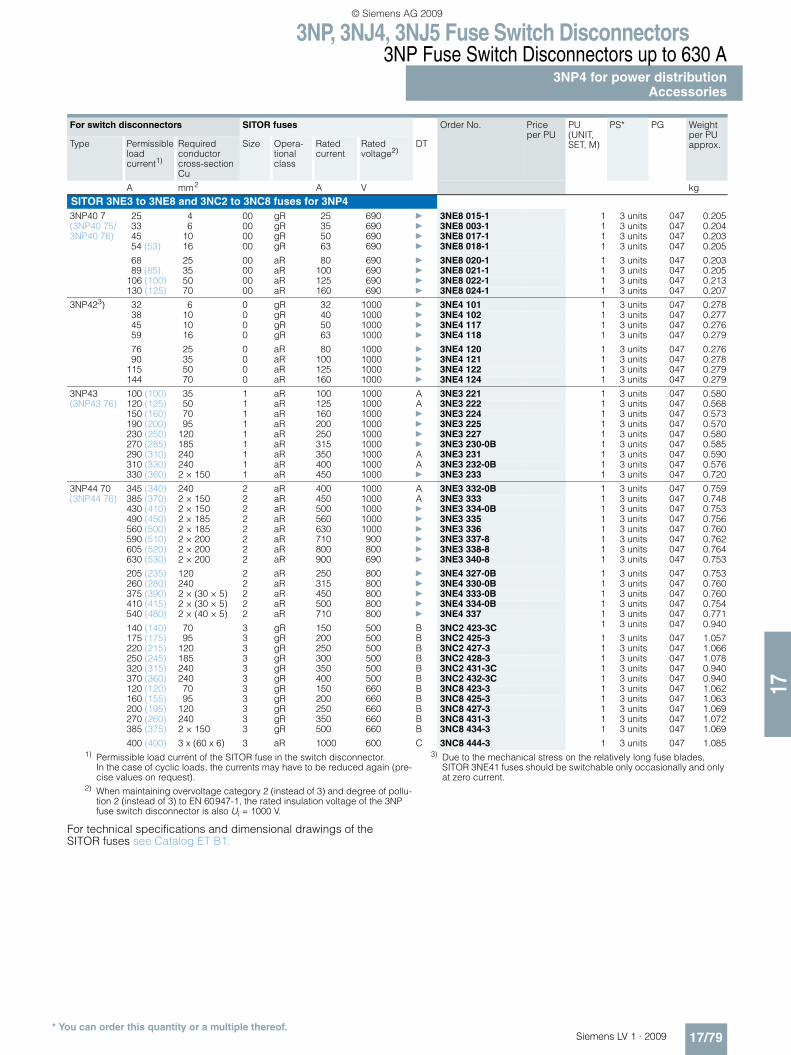
3NP54 360 240 2 aR 400 1000 A 3NE3 332-0B 1 3 units 047 0.759400 2 x 150 2 aR 450 1000 A 3NE3 333 1 3 units 047 0.748450 2 x 150 2 aR 500 1000 } 3NE3 334-0B 1 3 units 047 0.753510 2 x 185 2 aR 560 1000 } 3NE3 335 1 3 units 047 0.756580 2 x 185 2 aR 630 1000 } 3NE3 336 1 3 units 047 0.760630 2 × 200 2 aR 710 900 } 3NE3 337-8 1 3 units 047 0.762630 2 × 200 2 aR 800 800 } 3NE3 338-8 1 3 units 047 0.764630 2 × 200 2 aR 900 690 } 3NE3 340-8 1 3 units 047 0.753
450 2 x (30 x 5) 2 aR 500 800 } 3NE4 334-0B 1 3 units 047 0.754600 2 x (40 x 5) 2 aR 710 800 } 3NE4 337 1 3 units 047 0.771
145 70 3 gR 150 500 B 3NC2 423-3C 1 3 units 047 0.940180 95 3 gR 200 500 B 3NC2 425-3 1 3 units 047 1.057225 120 3 gR 250 500 B 3NC2 427-3 1 3 units 047 1.066255 185 3 gR 300 500 B 3NC2 428-3 1 3 units 047 1.078330 240 3 gR 350 500 B 3NC2 431-3C 1 3 units 047 0.940400 240 3 gR 400 500 B 3NC2 432-3C 1 3 units 047 0.940
135 70 3 gR 150 660 B 3NC8 423-3 1 3 units 047 1.062180 95 3 gR 200 660 B 3NC8 425-3 1 3 units 047 1.063225 120 3 gR 250 660 B 3NC8 427-3 1 3 units 047 1.069300 240 3 gR 350 660 B 3NC8 431-3 1 3 units 047 1.072425 2 x 150 3 gR 500 660 B 3NC8 434-3 1 3 units 047 1.069800 3 x (60 x 6) 3 aR 1000 600 C 3NC8 444-3 1 3 units 047 1.085
1) In the case of cyclic loads, the currents may have to be reduced again (pre-cise values on request).
2) When maintaining overvoltage category 2 (instead of 3) and degree of pol-lution 2 (instead of 3) to EN 60947-1, the rated insulation voltage of the 3NP fuse switch disconnector is also Ui = 1000 V.
3) Due to the mechanical stress on the relatively long fuse blades, SITOR 3NE41 fuses should be switchable only occasionally and only at zero current.
LV1_09_Gesamt_EN.book Seite 91 Mittwoch, 11. Februar 2009 3:54 15
© Siemens AG 2009

3NP, 3NJ4, 3NJ5 Fuse Switch Disconnectors3NP Fuse Switch Disconnectors up to 630 A3NP5 for extended technical requirementsAssembly kits for distribution boards
17/92 Siemens LV 1 · 2009* You can order this quantity or a multiple thereof.
17
■ Selection and ordering data
1) Also available in 2-wire version: 1 × 2.5 mm2 ... 50 mm2 and 1 × 2.5 mm2 ... 35 mm2.
2) Disconnector is wider than adapter. The adapter can, however, be expanded to 276 mm with two 8US19 98-2BM00 side modules.
For fuse switch disconnectors
Dimensions DT Order No. Price per PU
PU (UNIT, SET, M)
PS* PG Weight per PU approx.
mm kg
For installation in any distribution boardMolded-plastic masking frames Height × Width
For installation in the cabinet 3NP50 with and without auxil-iary switch
215 × 135 A 3NY1 105 1 1 unit 103 0.045
With auxiliary switch
215 × 135 A 3NY1 115 1 1 unit 103 0.044
For installation in metal front plates
With and with-out auxiliary switch
220 × 160 A 3NY1 125 1 1 unit 103 0.062
3NY1 107
For covering the connection terminals
3NP50 with and without auxil-iary switch
265 × 135 A 3NY1 107 1 1 unit 103 0.073
3NY1 106
For covering the cable lug connections
3NP50 with and without auxil-iary switch
290 × 135 A 3NY1 106 1 1 unit 103 0.071
For separate covering of the upper and lower cable lug connections
With auxiliary switch
290 × 135 A 3NY1 116 1 1 unit 103 0.071
3NP50 with and without auxil-iary switch
290 × 135 A 3NY1 108 1 1 unit 103 0.048
3NY1 212
Assembly kits for flush mounting
With molded-plastic mask-ing frame, fixing brackets and small parts. For discon-nectors with and without aux-iliary switches
3NP50 60 250 × 149 B 3NY1 208 1 1 unit 103 0.531
3NP52 60 300 × 220 B 3NY1 210 1 1 unit 103 0.287
3NP53 60 300 × 245 B 3NY1 211 1 1 unit 103 0.298
3NP54 60 300 × 290 B 3NY1 212 1 1 unit 103 0.313
Covers for cable lug connections Cover length
3TX6 546-3B
(1 set = 6 units) can be screwed onto free screw end to protect against accidental touch
3NP52 99 A 3NY1 241 1 1 unit 103 0.205
3NP53/3NP54 95 B 3TX6 546-3B 1 1 unit 101 0.260
120 B 3NY1 245 1 1 unit 103 0.336
3NY1 907
Clamp terminals(1 set = 3 units)
Conductor cross-section
3NP50 2.5 ... 50 mm2 1) B 3NY1 903 1 1 unit 103 0.108
3NP52 35 ... 120 mm2 B 3NY1 907 1 1 unit 103 0.225
8US12 10-4AG00
Busbar adapters Busbar width
For 60 mm busbar system 3NP50 108 A 8US12 91-4SB00 1 1 unit 143 0.551
3NP52, 3NP53, 3NP542)
250 (length 320 mm, M10 terminal screws, connecting cables must be manufactured)
A 8US12 10-4AG00 1 1 unit 143 3.060
Sealing lugs 3NP50 B 3NY1 940 1 1 unit 103 0.010Retrofittable (1 pack = 10 units)
LV1_09_Gesamt_EN.book Seite 92 Mittwoch, 11. Februar 2009 3:54 15
© Siemens AG 2009

3NP, 3NJ4, 3NJ5 Fuse Switch Disconnectors3NJ4, 3NJ5 In-Line Fuse Switch Disconnectors up to 1250 A
General data
17/93Siemens LV 1 · 2009
17
■ Overview
3NJ4 fuse switch disconnector
All key product features at a glance• Compliant with IEC/EN 60439-1, IEC/EN 60947-3• Voltage levels up to 690 V AC• Rated operational current from 160 A to 1250 A• Fuse links according to DIN 43620 Part 1 can be used –
nickel-plated fuse blades are not permissible due to the high transfer resistance
• In open position safe from touch by the back of the hand (exception 3NJ56: IP00)
• Parking position for maintenance• 1-pole or 3-pole switchable• Vertical and horizontal mounting position• Climate-proof• Degree of protection IP30 with closed fuse carriers, IP10 with
open fuse carriers (exception 3NJ56: IP00)
Overview of all components and accessory parts: 3NJ4/3NJ5 in size 00
4
8
6
6
9
3
1
12
11
13
7
14
2
10
5
CoverTerminal stripBusbar terminal
Current transformerDistance compensationConnection moduleFlat connector
Saddle terminalPrism terminalBox terminalCover3NJ4/5 fuse switch disconnectorBasic device size 00
Auxiliary switch mounting kit
Adapter for screw fixing on busbar systems
1234
5678
910111213
14
LV1_09_Gesamt_EN.book Seite 93 Mittwoch, 11. Februar 2009 3:54 15
© Siemens AG 2009
3NP, 3NJ4, 3NJ5 Fuse Switch Disconnectors3NJ4, 3NJ5 In-Line Fuse Switch Disconnectors up to 1250 A
General data
17/94 Siemens LV 1 · 2009
17
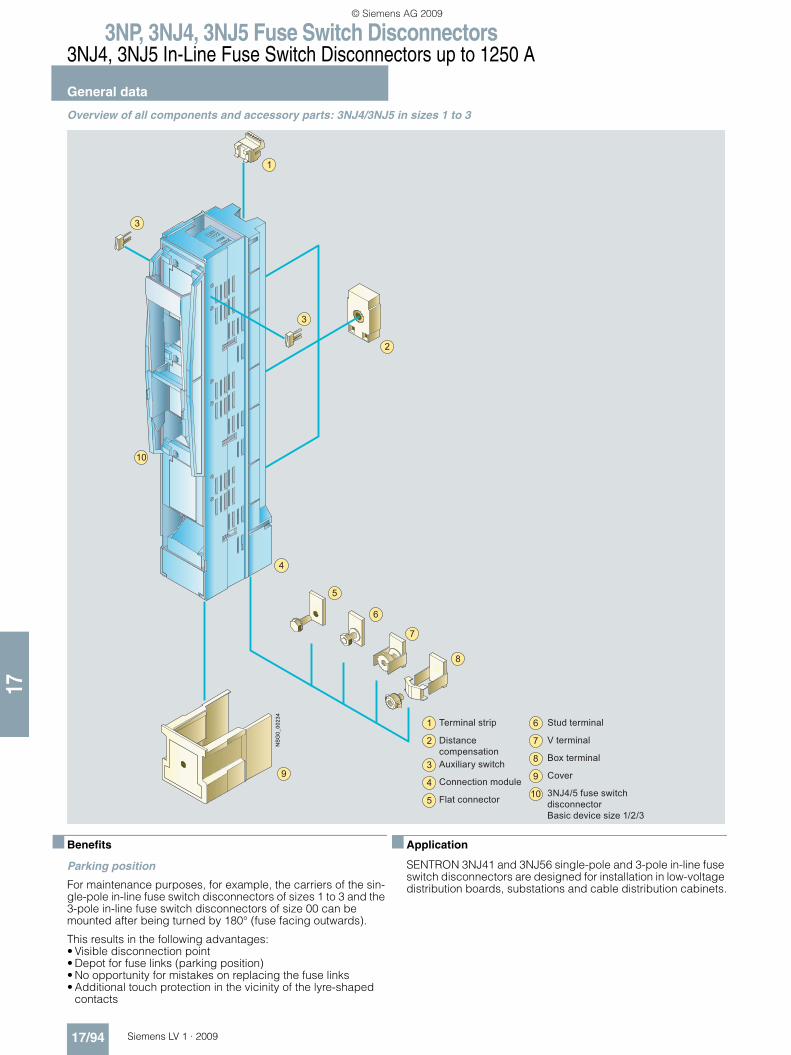
Overview of all components and accessory parts: 3NJ4/3NJ5 in sizes 1 to 3
■ Benefits
Parking position
For maintenance purposes, for example, the carriers of the sin-gle-pole in-line fuse switch disconnectors of sizes 1 to 3 and the 3-pole in-line fuse switch disconnectors of size 00 can be mounted after being turned by 180° (fuse facing outwards).
This results in the following advantages:• Visible disconnection point• Depot for fuse links (parking position)• No opportunity for mistakes on replacing the fuse links• Additional touch protection in the vicinity of the lyre-shaped
contacts
■ Application
SENTRON 3NJ41 and 3NJ56 single-pole and 3-pole in-line fuse switch disconnectors are designed for installation in low-voltage distribution boards, substations and cable distribution cabinets.
4
7
6
8
3
3
1
10
2
9
5
Terminal strip
Distance compensationAuxiliary switch
Connection module
Flat connector
Stud terminal
V terminal
Box terminal
Cover
3NJ4/5 fuse switch disconnectorBasic device size 1/2/3
1
2
3
4
5
6
7
8
9
10
LV1_09_Gesamt_EN.book Seite 94 Mittwoch, 11. Februar 2009 3:54 15
© Siemens AG 2009

3NP, 3NJ4, 3NJ5 Fuse Switch Disconnectors3NJ4, 3NJ5 In-Line Fuse Switch Disconnectors up to 1250 A
1-pole switchable
17/95Siemens LV 1 · 2009* You can order this quantity or a multiple thereof.
17
■ Selection and ordering data
1) Fixing screws for mounting on busbars must be ordered separately.
Rated operational current Ie
Center-to-center spacing
Connection type (terminal screws/ clamp-type terminals included in the scope of supply)1) optionally top or bottom (rotatable!)
DT Order No. Price per PU
PU (UNIT, SET, M)
PS* PG Weight per PUapprox.
kg
For fuse links according to DIN 43620
In-line fuse switch disconnectors, 1-pole switchable
3NJ41 21-3BF01
160 00 and 000
185 M8 flat connector D 3NJ50 13-0BD00 1 1 unit 143 2.561
250 1 185 M10 flat connector A 3NJ41 21-3BF01 1 1 unit 143 5.284
400 2 and 1 185 M12 flat connector A 3NJ41 31-3BF01 1 1 unit 143 5.363
630 3 and 2 185 M12 flat connector D 3NJ41 41-3BF01 1 1 unit 143 6.098
1250 4a 185 M16 × 60 stud terminal A 3NJ56 43-0BB00 1 1 unit 143 23.608
In-line fuse switch disconnectors, 1-pole switchable, for integratable current transformers
3NJ41 21-3BF11
250 1 185 M10 flat connector D 3NJ41 21-3BF11 1 1 unit 143 5.690
400 2 and 1 185 M12 flat connector D 3NJ41 31-3BF11 1 1 unit 143 5.720
630 3 and 2 185 M12 flat connector D 3NJ41 41-3BF11 1 1 unit 143 6.680
LV1_09_Gesamt_EN.book Seite 95 Mittwoch, 11. Februar 2009 3:54 15
© Siemens AG 2009

3NP, 3NJ4, 3NJ5 Fuse Switch Disconnectors3NJ4, 3NJ5 In-Line Fuse Switch Disconnectors up to 1250 A
3-pole switchable
17/96 Siemens LV 1 · 2009* You can order this quantity or a multiple thereof.
17
■ Selection and ordering data
1) Fixing screws for mounting on busbars must be ordered separately.2) Retrospective exchange with fuse links of size 3 is possible. Thereby
reduction of the rated current to 630 A.
Rated operational current Ie
Center-to-center spacing
Connection type (terminal screws/ clamp-type terminals included in the scope of supply)1) optionally top or bottom (rotatable!)
DT Order No. Price per PU
PU (UNIT, SET, M)
PS* PG Weight per PU approx.For fuse links acc. to
DIN 43620
A Size mm kg
In-line fuse switch disconnectors, 3-pole switchable
3NJ41 23-3BF01
160 00 and 000 100 M8 flat connector } 3NJ41 03-3BF02 1 1 unit 143 1.400
F70 box terminal A 3NJ41 03-3BR02 1 1 unit 143 1.479
160 00 and 000 185 M8 flat connector D 3NJ50 33-0BD00 1 1 unit 143 2.608
250 1 185 M10 flat connector } 3NJ41 23-3BF01 1 1 unit 143 5.481
M12 stud terminal A 3NJ41 23-3BJ01 1 1 unit 143 5.512
V terminal A 3NJ41 23-3BT01 1 1 unit 143 5.908
400 2 and 1 185 M12 flat connector } 3NJ41 33-3BF01 1 1 unit 143 5.540
M12 stud terminal A 3NJ41 33-3BJ01 1 1 unit 143 5.580
V terminal A 3NJ41 33-3BT01 1 1 unit 143 5.899
630 3 and 2 185 M12 flat connector } 3NJ41 43-3BF01 1 1 unit 143 6.426
M12 stud terminal A 3NJ41 43-3BJ01 1 1 unit 143 6.321
V terminal A 3NJ41 43-3BT01 1 1 unit 143 6.675
In-line fuse switch disconnectors, 3-pole switchable, for integratable current transformers
3NJ41 23-3BF11
160 00 and 000 100 M8 flat connector } 3NJ41 03-3BF12 1 1 unit 143 1.140
250 1 185 M10 flat connector } 3NJ41 23-3BF11 1 1 unit 143 5.890
400 2 and 1 185 M12 flat connector } 3NJ41 33-3BF11 1 1 unit 143 5.910
630 3 and 2 185 M12 flat connector } 3NJ41 43-3BF11 1 1 unit 143 6.870
In-line infeed blocks, 3-pole switchable, flat connectors 2 × M121000 3 185 For infeed from cable
directly to busbars, with built-in isolating links2), corre-sponds to block size 3
D 3NJ41 53-5BD01 1 1 unit 143 11.030
910 3 185 For infeed from 630 kVA transformer to busbar system; For special fuses, for transformer protection (see "Accessories")
D 3NJ41 83-3BF01 1 1 unit 143 12.943
LV1_09_Gesamt_EN.book Seite 96 Mittwoch, 11. Februar 2009 3:54 15
© Siemens AG 2009

3NP, 3NJ4, 3NJ5 Fuse Switch Disconnectors3NJ4, 3NJ5 In-Line Fuse Switch Disconnectors up to 1250 A
Accessories
17/97Siemens LV 1 · 2009* You can order this quantity or a multiple thereof.
17
■ Selection and ordering data
1) With cable lugs and connection from above, the terminal cover can be extended by connecting two units together.
2) Can be shortened (in exchange for short cover, included in the scope of supply of the in-line disconnector).
For fuse switch disconnectors or dimensions
DT Order No. Price per PU
PU (UNIT, SET, M)
PS* PG Weight per PU approx.
kg
Covers
Size 00 Additional touch protection with use of cable lugs
3NJ50 33 A 3NJ49 12-1FA02 1 1 unit 143 0.090
33NJ49 12-1AA01
Covers1) Size 1 to 3 Additional touch protection with use of cable lugs or connection from above
3NJ41 2 to3NJ41 4,3NJ41 5,3NJ41 8
} 3NJ49 12-1AA01 1 1 unit 143 0.103
3NJ49 12-1EA00
Covers size 3 For double blocks
3NJ41 4 A 3NJ49 12-1EA00 1 1 unit 143 0.200
3NJ49 12-1DA02
Covers size 00 (can also be used as masking frame)
Top and bottom (1 set = 2 units: short and long2))for covering of extended cable lugs and for combining 3NJ41 03 with 3NJ41 2 to 3NJ41 4 in-line disconnectors
3NJ41 03 A 3NJ49 12-1DA02 1 1 unit 143 0.005
3NJ49 12-2AA01
Blanking covers For panel cutout
50 mm wide A 3NJ49 12-2AA00 1 1 unit 143 0.189
3NJ49 12-2BA00
According to the size of the switch disconnectors: sizes 1 to 3 (for fitting in the cutout of the control panels)
100 mm wide A 3NJ49 12-2BA00 1 1 unit 143 0.215
3NJ49 12-2CA01
For 3NJ41 03 50 mm wide A 3NJ49 12-2CA00 1 1 unit 143 0.090
3NJ49 18-0AAA00
Fixing clips (1 set = 4 units, including fixing accessories) 2 units per side, for fixing the cover of the control panel front
3NJ41 A 3NJ49 18-0AA00 1 1 unit 143 0.130
LV1_09_Gesamt_EN.book Seite 97 Mittwoch, 11. Februar 2009 3:54 15
© Siemens AG 2009
3NP, 3NJ4, 3NJ5 Fuse Switch Disconnectors3NJ4, 3NJ5 In-Line Fuse Switch Disconnectors up to 1250 A
Accessories
17/98 Siemens LV 1 · 2009* You can order this quantity or a multiple thereof.
17
For fuse switch disconnectors
DT Order No. Price per PU
PU (UNIT, SET, M)
PS* PG Weight per PU approx.
kg
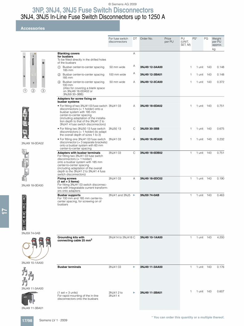
Blanking covers for busbars To be fitted directly in the drilled holes of the busbars
A
$ Busbar center-to-center spacing 185 mm
50 mm wide A 3NJ49 12-3AA00 1 1 unit 143 0.148
% Busbar center-to-center spacing 185 mm
100 mm wide A 3NJ49 12-3BA01 1 1 unit 143 0.148
& Busbar center-to-center spacing 100 mm(Also for covering a blank space on 3NJ49 18-0DA02 or 3NJ59 30–3BB)
50 mm wide A 3NJ49 12-3CA00 1 1 unit 143 0.372
Adapters for screw fixing on busbar systems
3NJ49 18-0DA02
3NJ49 18-0EA00
• For fitting of two 3NJ41 03 fuse switch disconnectors (= 1 holder) onto a busbar system with 185 mm center-to-center spacing (including adaptation of the installa-tion depth to that of the 3NJ41 2 to 3NJ41 4 fuse switch disconnectors)
3NJ41 03 A 3NJ49 18-0DA02 1 1 unit 143 0.751
• For fitting two 3NJ50 13 fuse switch disconnectors (= 1 holder) (to adapt the overall depth of sizes 1 to 3)
3NJ50 13 C 3NJ59 30-3BB 1 1 unit 143 0.675
• For fitting one 3NJ41 03 fuse switch disconnector (= 3 separate brackets) onto a busbar system with 60 mm center-to-center spacing
3NJ41 03 A 3NJ49 18-0EA00 1 1 unit 143 0.232
Adapters with busbar terminalsFor fitting two 3NJ41 03 fuse switch disconnectors (= 1 holder) onto a busbar system with 185 mm center-to-center spacing (including adaptation of the overall depth to the 3NJ41 2 to 3NJ41 4 fuse switch disconnectors)
3NJ41 03 C 3NJ49 18-0DB02 1 1 unit 143 0.751
Fixing screws (1 set = 3 items)For fitting 3NJ41 03 switch disconnec-tors with integratable current transform-ers onto adapters
3NJ41 03 A 3NJ49 18-0DC02 1 1 unit 143 0.190
3NJ59 74-0AB
Busbar supports For 100 mm and 185 mm center-to-center spacing, for screwing on of busbars
3NJ41 and 3NJ5 } 3NJ59 74-0AB 1 1 unit 143 0.463
3NJ49 10-1AA00
Grounding kits with connecting cable 25 mm2
3NJ414 to 3NJ418 C 3NJ49 10-1AA00 1 1 unit 143 4.200
3NJ49 11-3AA00
Busbar terminals 3NJ41 03 } 3NJ49 11-3AA00 1 1 unit 143 0.176
3NJ49 11-3BA01
(1 set = 3 units) For rapid mounting of the in-line disconnectors onto the busbars
3NJ41 2 to 3NJ41 4
} 3NJ49 11-3BA01 1 1 unit 143 0.607
LV1_09_Gesamt_EN.book Seite 98 Mittwoch, 11. Februar 2009 3:54 15
© Siemens AG 2009

3NP, 3NJ4, 3NJ5 Fuse Switch Disconnectors3NJ4, 3NJ5 In-Line Fuse Switch Disconnectors up to 1250 A
Accessories
17/99Siemens LV 1 · 2009* You can order this quantity or a multiple thereof.
17
For fuse switch disconnectors
DT Order No. Price per PU
PU (UNIT, SET, M)
PS* PG Weight per PU approx.
kg
3NJ49 11-4AA00
Saddle terminals(1 set = 3 units) Copper terminal 1.5 mm2 to 70 mm2
3NJ41 03 A 3NJ49 11-4AA00 1 1 unit 143 0.041
3NJ49 11-1AA00
Prism terminal assembly kits (1 set = 3 units) Aluminum/copper terminal 10 mm2 to 70 mm2
3NJ41 03 D 3NJ49 11-1AA00 1 1 unit 143 0.098
3NJ4911-2BQ00
Box terminal assembly kits (1 set = 3 units) Aluminum/copper terminal 95 mm2 to 240 mm2 (for connection to version with flat connector)
3NJ41 2 to 3NJ41 4
D 3NJ49 11-2BQ00 1 1 unit 143 0.949
Connection assembly kits for LV HRC 1, 2, 3with flat connector
3NJ49 11-5AA00
2 x 240 mm2 3NJ41 2 to 3NJ41 4
A 3NJ49 11-5AA00 1 1 unit 143 0.500
3NJ49 11-5BA00
2 x 300 mm2/3x 120 mm2 3NJ41 2 to 3NJ41 4
A 3NJ49 11-5BA00 1 1 unit 143 1.700
3NJ49 11-5CA00
1 x 400 mm2 3NJ41 2 to 3NJ41 4
A 3NJ49 11-5CA00 1 1 unit 143 1.800
Connection assembly kits for LV HRC 3 as double in-line blocks
3NJ49 11-6AA00
3 x 300 mm2/4 x 185 mm2 3NJ41 4 A 3NJ49 11-6AA00 1 1 unit 143 2.800
3NJ49 11-6BA00
4 x 240 mm2 3NJ41 4 A 3NJ49 11-6BA00 1 1 unit 143 3.800
LV1_09_Gesamt_EN.book Seite 99 Mittwoch, 11. Februar 2009 3:54 15
© Siemens AG 2009

3NP, 3NJ4, 3NJ5 Fuse Switch Disconnectors3NJ4, 3NJ5 In-Line Fuse Switch Disconnectors up to 1250 A
Accessories
17/100 Siemens LV 1 · 2009* You can order this quantity or a multiple thereof.
17
For fuse switch disconnectors
DT Order No. Price per PU
PU (UNIT, SET, M)
PS* PG Weight per PU approx.
kg
3NJ49 11-6BA00
Mechanical couplings of operating handles
3NJ41 4 A 3NJ49 11-6CA00 1 1 unit 143 0.150
3NJ49 13-6AA02
Auxiliary switch mounting kits 3NJ41 03 D 3NJ49 13-0AA02 1 1 unit 143 0.005
For sizes 1 to 3 with connecting cables, for 3-pole switchable switch discon-nectors only
3NJ41 2 to 3NJ41 4
A 3NJ49 13-1AA01 1 1 unit 143 0.029
Fuses 630 kVA 909 A Size LV HRC 3Specially for the protection of transformers (minimum order quantity 3 units)
3NJ41 8 D 3NJ49 14-8AA00 1 1 unit 143 1.341
3NJ49 14-8BA00
Isolating links
Size LV HRC 3, 1250 A
A 3NJ49 14-8BA00 1 1 unit 143 0.800
3NJ49 18-1AA00
Mounting hooks (one per in-line disconnector required)
A 3NJ49 18-1AA00 1 1 unit 143 0.120
3NJ49 15-1BA00
3NJ49 15-2BA00
Distance compensation 3NJ41 03 } 3NJ49 15-1BA00 1 1 unit 143 0.020
For fuse switch disconnectors, with integratable current transformers if no current transformer is built in.
3NJ4103,3NJ412 to 3NJ414
} 3NJ49 15-2BA00 1 1 unit 143 0.095
3NJ49 15-1CA00
3NJ49 15-2CA00
Terminal strips 3NJ41 03 } 3NJ49 15-1CA00 1 1 unit 143 0.030
3NJ41 2 to 3NJ41 4
} 3NJ49 15-2CA00 1 1 unit 143 0.110
LV1_09_Gesamt_EN.book Seite 100 Mittwoch, 11. Februar 2009 3:54 15
© Siemens AG 2009

3NP, 3NJ4, 3NJ5 Fuse Switch Disconnectors3NJ4, 3NJ5 In-Line Fuse Switch Disconnectors up to 1250 A
Accessories
17/101Siemens LV 1 · 2009* You can order this quantity or a multiple thereof.
17
For fuse switch disconnectors
DT Order No. Price per PU
PU (UNIT, SET, M)
PS* PG Weight per PU approx.
kg
Current transformers .../1 A
3NJ49 15-1FB20
100/1 A, Cl. 0.5, 1.5 VA 3NJ41 03 D 3NJ49 15-1EA10 1 1 unit 143 0.250100/1 A, Cl. 1, 2.0 VA 3NJ41 03 C 3NJ49 15-1EA20 1 1 unit 143 0.250150/1 A, Cl. 0.5, 2.5 VA 3NJ41 03 D 3NJ49 15-1FA10 1 1 unit 143 0.250150/1 A, Cl. 0.5 calibrated, 2.5 VA 3NJ41 03 D 3NJ49 15-1FA11 1 1 unit 143 0.250150/1 A, Cl. 1, 3.0 VA 3NJ41 03
}3NJ49 15-1FA20 1 1 unit 143 0.250
75/1 A, Cl. 1, 1.5 VA 3NJ41 2 to 3NJ41 4
D 3NJ49 15-2DA20 1 1 unit 143 0.190
100/1 A, Cl. 0.5, 1.5 VA 3NJ41 2 to 3NJ41 4
D 3NJ49 15-2EA10 1 1 unit 143 0.190
100/1 A, Cl. 1, 2.0 VA 3NJ41 2 to 3NJ41 4
D 3NJ49 15-2EA20 1 1 unit 143 0.190
150/1 A, Cl. 0.5, 2.5 VA 3NJ41 2 to 3NJ41 4
C 3NJ49 15-2FA10 1 1 unit 143 0.190
150/1 A, Cl. 1, 2.5 VA 3NJ41 2 to 3NJ41 4
D 3NJ49 15-2FA20 1 1 unit 143 0.190
250/1 A, Cl. 0.5, 2.5 VA 3NJ41 2 to 3NJ41 4
D 3NJ49 15-2GA10 1 1 unit 143 0.190
250/1 A, Cl. 0.5 calibrated, 2.5 VA 3NJ41 2 to 3NJ41 4
D 3NJ49 15-2GA11 1 1 unit 143 0.190
250/1 A, Cl. 1, 5.0 VA 3NJ41 2 to 3NJ41 4
} 3NJ49 15-2GA20 1 1 unit 143 0.190
3NJ49 15-2HA20
400/1 A, Cl. 0.5, 2.5 VA 3NJ41 2 to 3NJ41 4
D 3NJ49 15-2HA10 1 1 unit 143 0.190
400/1 A, Cl. 0.5 calibrated, 2.5 VA 3NJ41 2 to 3NJ41 4
D 3NJ49 15-2HA11 1 1 unit 143 0.190
400/1 A, Cl. 1, 5.0 VA 3NJ41 2 to 3NJ41 4
} 3NJ49 15-2HA20 1 1 unit 143 0.190
500/1 A, Cl. 0.5, 2.5 VA 3NJ41 2 to 3NJ41 4
D 3NJ49 15-2JA10 1 1 unit 143 0.190
500/1 A, Cl. 1, 5.0 VA 3NJ41 2 to 3NJ41 4
D 3NJ49 15-2JA20 1 1 unit 143 0.190
600/1 A, Cl. 0.5, 2.5 VA 3NJ41 2 to 3NJ41 4
D 3NJ49 15-2KA10 1 1 unit 143 0.190
600/1 A, Cl. 0.5 calibrated, 2.5 VA 3NJ41 2 to 3NJ41 4
D 3NJ49 15-2KA11 1 1 unit 143 0.190
600/1 A, Cl. 1, 5.0 VA 3NJ41 2 to 3NJ41 4
} 3NJ49 15-2KA20 1 1 unit 143 0.190
Current transformers .../5 A
100/5 A, Cl. 0.5, 1.0 VA 3NJ41 03 D 3NJ49 15-1EB10 1 1 unit 143 0.250
3NJ49 15-1FB20
100/5 A, Cl. 1, 1.5 VA 3NJ41 03 D 3NJ49 15-1EB20 1 1 unit 143 0.250150/5 A, Cl. 0.5, 1.5 VA 3NJ41 03 D 3NJ49 15-1FB10 1 1 unit 143 0.250150/5 A, Cl. 0.5 calibrated, 1.5 VA 3NJ41 03 D 3NJ49 15-1FB11 1 1 unit 143 0.250150/5 A, Cl. 1, 2.5 VA 3NJ41 03 } 3NJ49 15-1FB20 1 1 unit 143 0.25075/5 A, Cl. 1, 1.5 VA 3NJ41 2 to
3NJ41 4D 3NJ49 15-2DB20 1 1 unit 143 0.190
100/5 A, Cl. 0.5, 1.0 VA 3NJ41 2 to 3NJ41 4
D 3NJ49 15-2EB10 1 1 unit 143 0.190
100/5 A, Cl. 1, 2.0 VA 3NJ41 2 to 3NJ41 4
D 3NJ49 15-2EB20 1 1 unit 143 0.190
150/5 A, Cl. 0.5, 1.5 VA 3NJ41 2 to 3NJ41 4
D 3NJ49 15-2FB10 1 1 unit 143 0.190
150/5 A, Cl. 1, 2.5 VA 3NJ41 2 to 3NJ41 4
D 3NJ49 15-2FB20 1 1 unit 143 0.190
250/5 A, Cl. 0.5, 2.5 VA 3NJ41 2 to 3NJ41 4
D 3NJ49 15-2GB10 1 1 unit 143 0.190
250/5 A, Cl. 0.5 calibrated, 2.5 VA 3NJ41 2 to 3NJ41 4
D 3NJ49 15-2GB11 1 1 unit 143 0.190
250/5 A, Cl. 1, 3.75 VA 3NJ41 2 to 3NJ41 4
} 3NJ49 15-2GB20 1 1 unit 143 0.190
400/5 A, Cl. 0.5, 2.5 VA 3NJ41 2 to 3NJ41 4
D 3NJ49 15-2HB10 1 1 unit 143 0.190
3NJ49 15-2HB20
400/5 A, Cl. 0.5 calibrated, 2.5 VA 3NJ41 2 to 3NJ41 4
D 3NJ49 15-2HB11 1 1 unit 143 0.190
400/5 A, Cl. 1, 5.0 VA 3NJ41 2 to 3NJ41 4
} 3NJ49 15-2HB20 1 1 unit 143 0.190
500/5 A, Cl. 0.5, 2.5 VA 3NJ41 2 to 3NJ41 4
D 3NJ49 15-2JB10 1 1 unit 143 0.190
500/5 A, Cl. 1, 5.0 VA 3NJ41 2 to 3NJ41 4
D 3NJ49 15-2JB20 1 1 unit 143 0.190
600/5 A, Cl. 0.5, 2.5 VA 3NJ41 2 to 3NJ41 4
D 3NJ49 15-2KB10 1 1 unit 143 0.190
600/5 A, Cl. 0.5 calibrated, 2.5 VA 3NJ41 2 to 3NJ41 4
D 3NJ49 15-2KB11 1 1 unit 143 0.190
600/5 A, Cl. 1, 5.0 VA 3NJ41 2 to 3NJ41 4
} 3NJ49 15-2KB20 1 1 unit 143 0.190
LV1_09_Gesamt_EN.book Seite 101 Mittwoch, 11. Februar 2009 3:54 15
© Siemens AG 2009