Side STOWAWAY Loader - Thieman Tailgates · PARTS ORDERING PROCEDURE . . . . . . . . . . . . . . ....
20
S ide L oader Tailgates By THIEMAN SL15/20-6 AND SL15/20-10 OWNERS MANUAL/PARTS LIST IMPORTANT! KEEP IN VEHICLE! ! PLEASE READ AND UNDERSTAND THE CONTENTS OF THIS MANUAL BEFORE OPERATING THE EQUIPMENT. 600 East Wayne Street Celina, Ohio 45822 Phone: 419-586-7727 Fax: 419-586-9724 HIEMAN NATIONAL TRUCK EQUIPMENT ASSOCIATION Member STOWAWAY® TAILGATES, INC.
-
Upload
truongdieu -
Category
Documents
-
view
224 -
download
0
Transcript of Side STOWAWAY Loader - Thieman Tailgates · PARTS ORDERING PROCEDURE . . . . . . . . . . . . . . ....
SideLoaderTailgates By THIEMAN
SL15/20-6 AND SL15/20-10OWNERS MANUAL/PARTS LIST
IMPORTANT! KEEP IN VEHICLE!!PLEASE READ AND UNDERSTAND THE CONTENTS OF THIS
MANUAL BEFORE OPERATING THE EQUIPMENT.
600 East Wayne StreetCelina, Ohio 45822
Phone: 419-586-7727 Fax: 419-586-9724
HIEMANNATIONAL TRUCK EQUIPMENT ASSOCIATION
Member
STOWAWAY®
TAILGATES, INC.
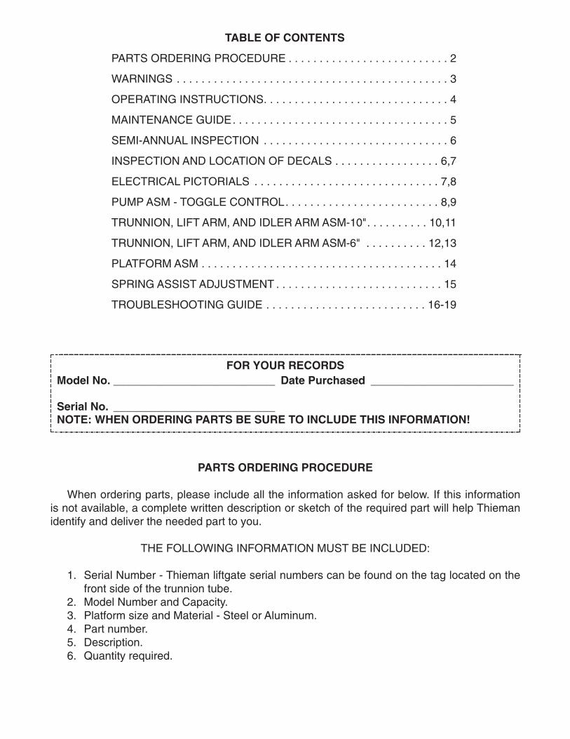
TABLE OF CONTENTS
PARTS ORDERING PROCEDURE . . . . . . . . . . . . . . . . . . . . . . . . . . 2
WARNINGS . . . . . . . . . . . . . . . . . . . . . . . . . . . . . . . . . . . . . . . . . . . . 3
OPERATING INSTRUCTIONS. . . . . . . . . . . . . . . . . . . . . . . . . . . . . . 4
MAINTENANCE GUIDE. . . . . . . . . . . . . . . . . . . . . . . . . . . . . . . . . . . 5
SEMI-ANNUAL INSPECTION . . . . . . . . . . . . . . . . . . . . . . . . . . . . . . 6
INSPECTION AND LOCATION OF DECALS . . . . . . . . . . . . . . . . . 6,7
ELECTRICAL PICTORIALS . . . . . . . . . . . . . . . . . . . . . . . . . . . . . . 7,8
PUMP ASM - TOGGLE CONTROL. . . . . . . . . . . . . . . . . . . . . . . . . 8,9
TRUNNION, LIFT ARM, AND IDLER ARM ASM-10". . . . . . . . . . 10,11
TRUNNION, LIFT ARM, AND IDLER ARM ASM-6" . . . . . . . . . . 12,13
PLATFORM ASM . . . . . . . . . . . . . . . . . . . . . . . . . . . . . . . . . . . . . . . 14
SPRING ASSIST ADJUSTMENT . . . . . . . . . . . . . . . . . . . . . . . . . . . 15
TROUBLESHOOTING GUIDE . . . . . . . . . . . . . . . . . . . . . . . . . . 16-19
FOR YOUR RECORDSModel No. __________________________ Date Purchased _______________________
Serial No. __________________________NOTE: WHEN ORDERING PARTS BE SURE TO INCLUDE THIS INFORMATION!
PARTS ORDERING PROCEDURE
When ordering parts, please include all the information asked for below. If this informationis not available, a complete written description or sketch of the required part will help Thiemanidentify and deliver the needed part to you.
THE FOLLOWING INFORMATION MUST BE INCLUDED:
1. Serial Number - Thieman liftgate serial numbers can be found on the tag located on thefront side of the trunnion tube.
2. Model Number and Capacity.3. Platform size and Material - Steel or Aluminum. 4. Part number.5. Description.6. Quantity required.
3.
WARNING!
The following list of warnings are to be read before operating the SL series liftgate.
+ Read this Owner’s Manual and all of the decals on the liftgate BEFORE operating the liftgate.+ All protective covers and guards must be in place before operating the liftgate.+ DO NOT operate the liftgate if you do not have a thorough knowledge and understanding of
the operation of the liftgate. + NEVER OVERLOAD THE LIFTGATE. The maximum rated capacity of the SL series liftgate
differs with each model as follows:SL15 - 1500lbs.SL 20 - 2000lbs.
+ Never use the liftgate if it makes any unusual noises, has vibrations, or fails to operatefreely.
+ Make certain that the area below the platform is clear before and at all times during theoperation of the liftgate.
+ Keep hands and feet clear of all pinch points.
WATER LEVEL LOADING
When a maximum load is to be raised or lowered, this load must be centered on theload bearing platform, both front to back and side to side.

4.
+ The platform must be in the closed position and the transit chains attached properly beforetransit.
+ Always load as close to the center of the platform and as close to the vehicle as possible.See Figure 1.
+ Never operate lift trucks on or over any part of the platform.+ Load and unload the platform from the rear and not from the side of the platform.+ Only operate liftgate when vehicle is on level ground and the parking brake is set.+ Follow the maintenance guide as outlined in this manual.+ DO NOT attempt any repairs unless you are a qualified and authorized THIEMAN distributor.+ If any repairs, adjustments, or maintenance not covered in this manual are required, contact
your nearest Thieman distributor or the factory.+ DO NOT ride the liftgate, it is not intended as a personnel lift.+ This liftgate is intended for the use of loading and unloading cargo only, and is not to be
used for anything other than this.+ DO NOT modify this liftgate. Altering this liftgate may cause serious personal injury or damage
the liftgate and will void all warranties.
OPERATING INSTRUCTIONS
CautionBe sure to operate liftgate at a safe distance and never improperly load platform as this maycause personal injury or damage to the liftgate.
UNFOLDING OF PLATFORM1. Raise platform by pushing the raise switch up until tension is removed from stow chains.2. Unhook stow chains from lift arms.3. Lower platform by pushing the lower switch until the platform is approximately 3/4 of the
way to the ground.4. Using platform handles, manually lift and pull platform until lift arms are fully extended.5. Manually unfold platform extension and ramp.
RAISING OF PLATFORM1. Push raise switch to raise platform to bed height.
LOWERING OF PLATFORM1. Push lower switch to lower platform to the ground.
CLOSING OF PLATFORM1. Raise platform approximately 6” from the ground.2. Manually fold platform extension and ramp.3. Using platform handles, manually lift and push platform into the folded position.4. Raise gate into the stowed position.5. Attach stow chains to lift arms.
THERMAL DATA: To avoid overheating the motor do not operate this unit for more than 14cycles/10 minutes with the maximum load. The motor then must be allowed to completely cooldown to ambient temperature before cycling the lift again. This unit also has a 12% duty cycle,which means the liftgate can be cycled no more than 5 cycles/10 minutes constantly with amaximum load.

5.
MAINTENANCE GUIDE
The following inspection and maintenance operations should be performed at therecommended intervals or anytime the liftgate shows signs of abuse, and improper orabnormal operation.
MONTHLY INSPECTION AND MAINTENANCE
Operate the liftgate throughout its entire operational cycle and check the following:1. Check that there are no unusual noises or vibrations.2. Check platform height relative to bed height. If platform is lower, adjust cylinder with a
13/16 wrench to obtain the necessary height.3. Check for apparent damage to the liftgate such as bent or distorted members, any cracked
welds that may have resulted from overloading or abuse.4. Check for excessive wear in the following areas:
A. Platform hinge pins and bushingsB. All cylinder pins, bolts, and bushings
5. Check that the platform pivot pins are in place and retained by their proper retainers.6. Check that all protective covers and guards are properly in place and secured.7. Check for oil leaks in these areas:
A. Lift cylinderB. Hydraulic hose – replace if it shows signs of wear or cracking.C. Hydraulic fittings – tighten or replace as may be required to stop leakage. D. Hydraulic dampers – replace leaking damper with new hydraulic damper.
8. Check the oil level in the pump reservoir. With the liftgate in the stowed position the oilshould be within 1/2” from the top of the reservoir. See chart below for oil applications.
9. Check that all wiring and battery cable connections are tight and free of corrosion.10.Lubrication of the SL series liftgate should be as follows for all user conditions:
Area of Tailgate Type of Lubrication FrequencyPivot pins w/ zerk Grease+ 50 cyclesPump oil change see chart below yearly
*Most of the pivot points on the SL have special bushings that do not require lubrication.+See the parts list for the location of the grease zerks.For -40 to 120 F use #0 Grade grease.For -20 to 200 F use #1 Grade grease.
Temperature Range-20 to 130 F
-50 to 80 F
-75 to 165 F
Acceptable FluidsDexron IIIExxon Superflo ATFShell Donax TG
Shell Aero Fluid 4Mobil Aero HFAExxon Univis J-13MIL H-5606
Exxon Univis J-26
HYDRAULIC FLUID CHART
6.
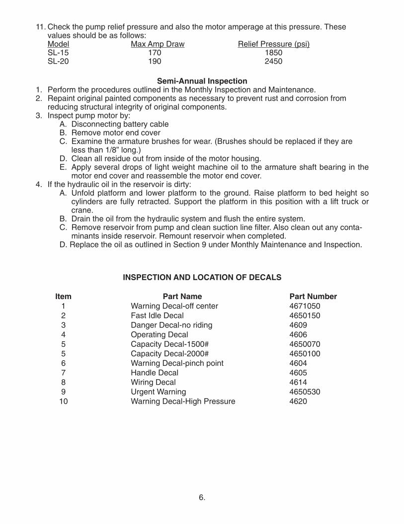
Semi-Annual Inspection1. Perform the procedures outlined in the Monthly Inspection and Maintenance.2. Repaint original painted components as necessary to prevent rust and corrosion from
reducing structural integrity of original components.3. Inspect pump motor by:
A. Disconnecting battery cableB. Remove motor end coverC. Examine the armature brushes for wear. (Brushes should be replaced if they are
less than 1/8” long.)D. Clean all residue out from inside of the motor housing.E. Apply several drops of light weight machine oil to the armature shaft bearing in the
motor end cover and reassemble the motor end cover.4. If the hydraulic oil in the reservoir is dirty:
A. Unfold platform and lower platform to the ground. Raise platform to bed height socylinders are fully retracted. Support the platform in this position with a lift truck orcrane.
B. Drain the oil from the hydraulic system and flush the entire system.C. Remove reservoir from pump and clean suction line filter. Also clean out any conta-
minants inside reservoir. Remount reservoir when completed.D. Replace the oil as outlined in Section 9 under Monthly Maintenance and Inspection.
11. Check the pump relief pressure and also the motor amperage at this pressure. Thesevalues should be as follows:Model Max Amp Draw Relief Pressure (psi)SL-15 170 1850SL-20 190 2450
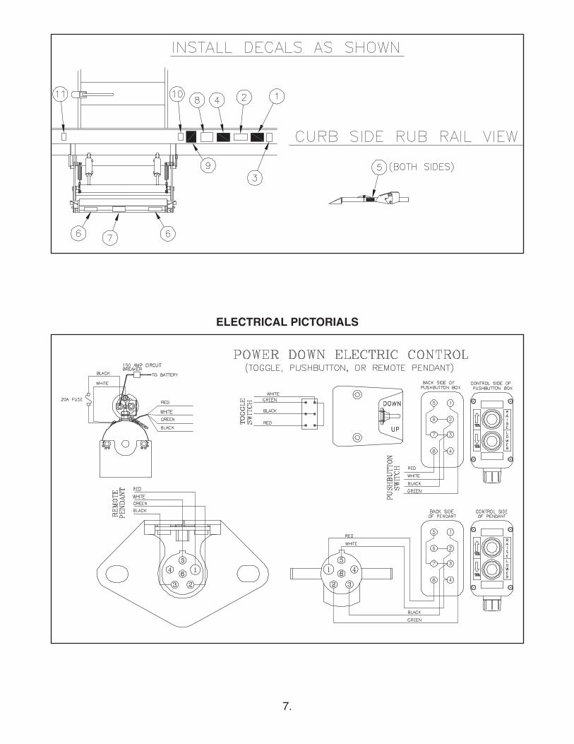
INSPECTION AND LOCATION OF DECALS
Item Part Name Part Number1 Warning Decal-off center 46710502 Fast Idle Decal 46501503 Danger Decal-no riding 46094 Operating Decal 46065 Capacity Decal-1500# 46500705 Capacity Decal-2000# 46501006 Warning Decal-pinch point 46047 Handle Decal 46058 Wiring Decal 46149 Urgent Warning 4650530
10 Warning Decal-High Pressure 4620
7.
ELECTRICAL PICTORIALS

8.
9.
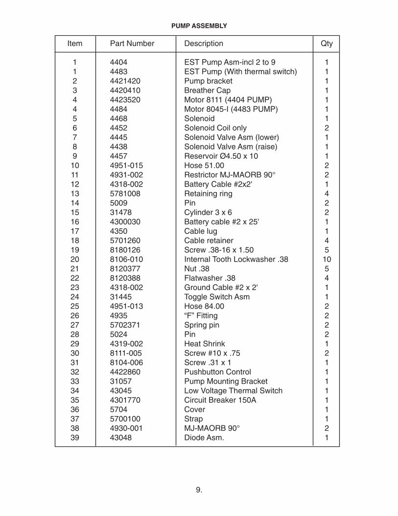
PUMP ASSEMBLY
Item Part Number Description Qty
1 4404 EST Pump Asm-incl 2 to 9 11 4483 EST Pump (With thermal switch) 12 4421420 Pump bracket 13 4420410 Breather Cap 14 4423520 Motor 8111 (4404 PUMP) 14 4484 Motor 8045-I (4483 PUMP) 15 4468 Solenoid 16 4452 Solenoid Coil only 27 4445 Solenoid Valve Asm (lower) 18 4438 Solenoid Valve Asm (raise) 19 4457 Reservoir Ø4.50 x 10 110 4951-015 Hose 51.00 211 4931-002 Restrictor MJ-MAORB 90° 212 4318-002 Battery Cable #2x2' 113 5781008 Retaining ring 414 5009 Pin 215 31478 Cylinder 3 x 6 216 4300030 Battery cable #2 x 25' 117 4350 Cable lug 118 5701260 Cable retainer 419 8180126 Screw .38-16 x 1.50 520 8106-010 Internal Tooth Lockwasher .38 1021 8120377 Nut .38 522 8120388 Flatwasher .38 423 4318-002 Ground Cable #2 x 2' 124 31445 Toggle Switch Asm 125 4951-013 Hose 84.00 226 4935 “F” Fitting 227 5702371 Spring pin 228 5024 Pin 229 4319-002 Heat Shrink 130 8111-005 Screw #10 x .75 231 8104-006 Screw .31 x 1 132 4422860 Pushbutton Control 133 31057 Pump Mounting Bracket 134 43045 Low Voltage Thermal Switch 135 4301770 Circuit Breaker 150A 136 5704 Cover 137 5700100 Strap 138 4930-001 MJ-MAORB 90° 239 43048 Diode Asm. 1

10.

11.
Item Part Number Description Qty
1 31046 Trunnion asm (48 wide) 11 31610 Trunnion asm (60 wide) 12 31603 Lift arm asm (48 wide) 12 31605 Lift arm asm (60 wide) 13 5770 Hydraulic Damper 24 8104-012 SS Screw .31-18x1.00 45 8103-013 SS Locknut .31 (nylon ins) 46 8107-004 SS Flatwasher .31 47 31059 Idler arm 28 3110-002 Strap weld RH 19 3110-001 Strap weld LH 110 5019 Adjustment rod 211 31374 Clevis LH thread 212 31373 Clevis RH thread 213 5101120 Spring 214 5507-001 Bronze Bushing 215 31606 Chain Asm 216 5708-001 Spring pin 417 5781008 Retaining ring 1618 4103 Chain Link 219 4109-019 Chain-Four Links 220 31595 Spring Link Weld 221 9413534 Locknut .38 222 5793002 Screw .38 x 1.25 223 8107-008 Flatwasher 1.00 424 8271291 Zerk 625 31284-001 Leveling strap LH 126 31284-002 Leveling strap RH 127 5009 Pin 228 5024 Pin 229 8121222 Cotter Pin 430 5018 Pin 231 5504-001 Bushing 832 5504-005 Bushing 1233 8107-010 Flatwasher 1.00 234 5702371 Spring pin 235 5017 Pin 236 8120396 Flatwasher .50 437 4220240 Insert 438 8181635 Screw .38-24 x .75 439 2037000 4 x 6 x .38 angle 2
TRUNNION, LIFT ARM, & IDLER ARM ASM-10”
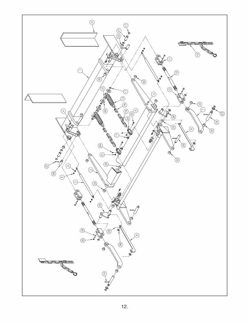
12.
13.
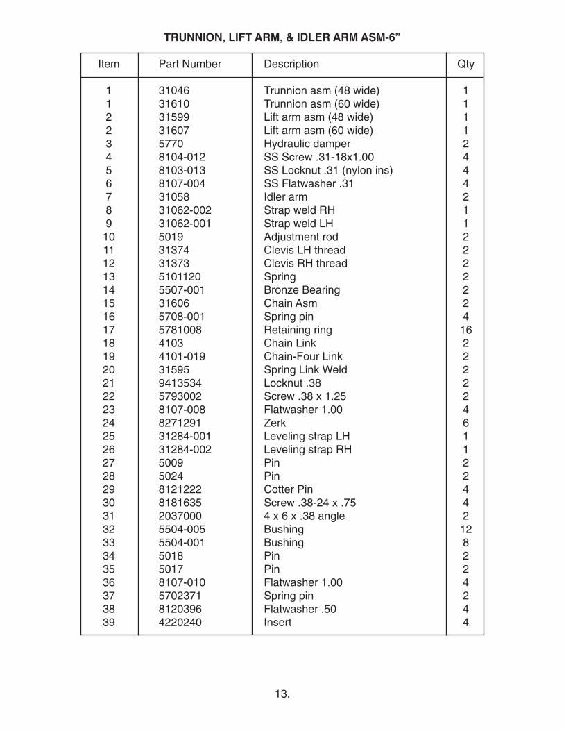
Item Part Number Description Qty
1 31046 Trunnion asm (48 wide) 11 31610 Trunnion asm (60 wide) 12 31599 Lift arm asm (48 wide) 12 31607 Lift arm asm (60 wide) 13 5770 Hydraulic damper 24 8104-012 SS Screw .31-18x1.00 45 8103-013 SS Locknut .31 (nylon ins) 46 8107-004 SS Flatwasher .31 47 31058 Idler arm 28 31062-002 Strap weld RH 19 31062-001 Strap weld LH 110 5019 Adjustment rod 211 31374 Clevis LH thread 212 31373 Clevis RH thread 213 5101120 Spring 214 5507-001 Bronze Bearing 215 31606 Chain Asm 216 5708-001 Spring pin 417 5781008 Retaining ring 1618 4103 Chain Link 219 4101-019 Chain-Four Link 220 31595 Spring Link Weld 221 9413534 Locknut .38 222 5793002 Screw .38 x 1.25 223 8107-008 Flatwasher 1.00 424 8271291 Zerk 625 31284-001 Leveling strap LH 126 31284-002 Leveling strap RH 127 5009 Pin 228 5024 Pin 229 8121222 Cotter Pin 430 8181635 Screw .38-24 x .75 431 2037000 4 x 6 x .38 angle 232 5504-005 Bushing 1233 5504-001 Bushing 834 5018 Pin 235 5017 Pin 236 8107-010 Flatwasher 1.00 437 5702371 Spring pin 238 8120396 Flatwasher .50 439 4220240 Insert 4
TRUNNION, LIFT ARM, & IDLER ARM ASM-6”

14.
PLATFORM ASSEMBLY
Item Part Number Description Qty
1 3406 Platform Asm-incl 2 to 6 48 11 3453 Platform Asm-incl 2 to 6 60 12 31023 Plat. main (48 wide) 1 2 31609 Plat. main (60 wide) 13 31024 Platform extension (48 wide) 13 31608 Platform extension (60 wide) 14 5056 Pin 25 5781001 Retaining ring 46 31020-002 Platform hinge RH 17 31020-001 Platform hinge LH 18 8120382 Lockwasher .38 12 9 8108-001 Screw .38-16 x 1.75 SS 1210 8107-011 Washer .62 2

15.
SPRING ASSIST ADJUSTMENT
Notes: 1. The platform manual fold/unfold assist spring adjustment is preset at the factory to bestcover the entire bed height range of the SL liftgate. However, the spring assist isadjustable to suit the personal tastes of the operator and their particular installed bedheight.
2. Adjusting the spring assist so the platform is easier to fold, may make the liftgate harderto unfold because the spring will start stretching earlier. Also, when the platform isfolded back into the stored position the spring may start to pull the operator toward thetruck more than they would like. The spring should be adjusted to give the best balancebetween ease of folding and ease of unfolding.
3. The liftgate should be folded and unfolded as close to the ground as is comfortablebecause this is where the spring assist is the greatest and is where it takes the leastamount to fold. It is also easier to unfold in this position with the liftarm fully lowered,because the mechanism brings the platform closer to falling over center.
4. After spring adjustments have been made, make sure that when the liftgate is unfoldedand on the ground, the spring’s extended length does not exceed the 21.00 inchmaximum when measured from the inside of one looped end to the other on the springitself as shown below.
5. The SL liftgate ships with what is labeled below as the standard setup. The standardsetup uses 4 chain links between the quick link and the spring link weld and the chainlinks are bolted to hole 1 on the spring link weld. This is the second strongest setting forthe spring assist, which makes it easier to fold. The only way to add more assist is touse three chain links (let one link dangle as shown) and bolt the chain links to hole 4 onthe springlink weld. To lessen the spring assist, which will make the liftgate easier tounfold but harder to fold, simply use all four chain links from the standard setup and boltthe chain links to hole 2, 3 or 4 on the spring link weld. Use steps below for makingspring adjustments.
Step 1 With the liftgates safety stow chains connected but as loose as possible, lower the liftgateout of the stored position just enough so that the retaining rings can be removed from the1.00 dia. pins on the liftarm, which the spring link welds are slid over. Do not power theliftgate down once the stow chains are tight. Make sure that there is no tension on the foldassist springs before proceeding.
Step 2 Slide the spring link welds off of the 1.00 dia. pins on the liftarms.
Step 3 Select one of the five spring assist settings shown below by selecting which hole of thespring link weld the chain links are bolted to and whether 3 or 4 chain links are used. Makesure all fasteners are secured tightly once the desired setting is selected.
Step 4 Slide the spring link welds back on to the 1.00 dia. pins on the liftarms and re-installretaining rings.
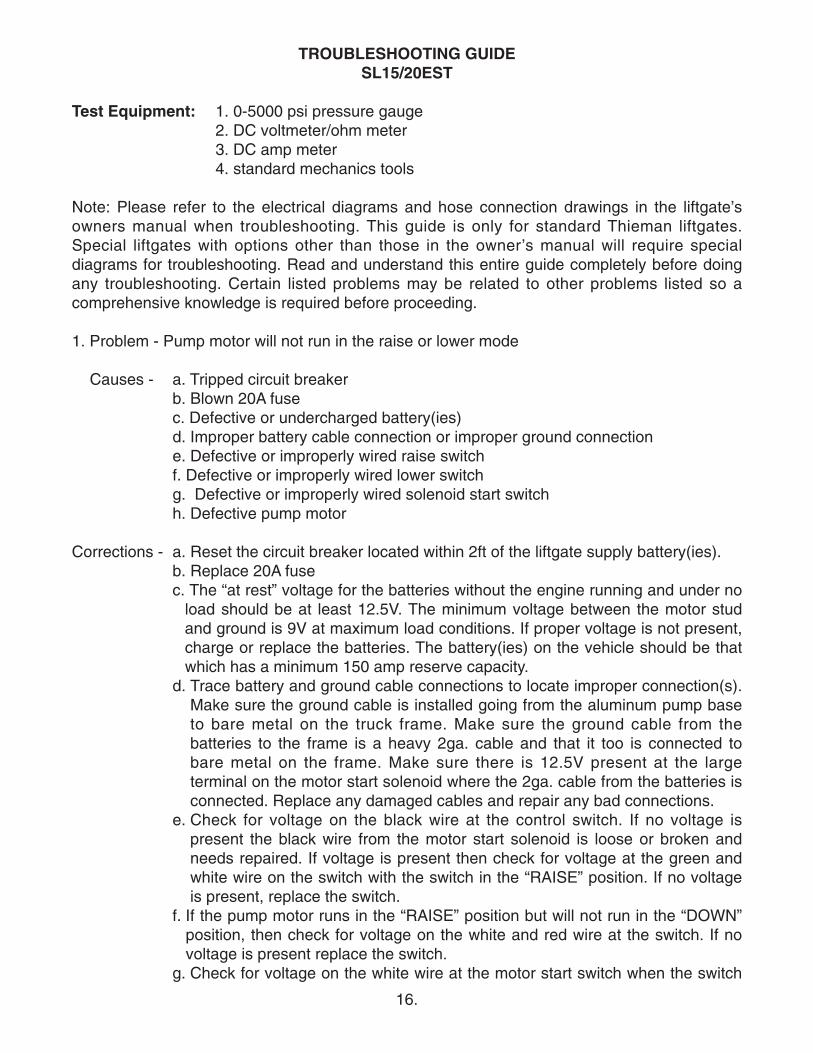
TROUBLESHOOTING GUIDE SL15/20EST
Test Equipment: 1. 0-5000 psi pressure gauge2. DC voltmeter/ohm meter3. DC amp meter4. standard mechanics tools
Note: Please refer to the electrical diagrams and hose connection drawings in the liftgate’sowners manual when troubleshooting. This guide is only for standard Thieman liftgates.Special liftgates with options other than those in the owner’s manual will require specialdiagrams for troubleshooting. Read and understand this entire guide completely before doingany troubleshooting. Certain listed problems may be related to other problems listed so acomprehensive knowledge is required before proceeding.
1. Problem - Pump motor will not run in the raise or lower mode
Causes - a. Tripped circuit breakerb. Blown 20A fusec. Defective or undercharged battery(ies)d. Improper battery cable connection or improper ground connectione. Defective or improperly wired raise switchf. Defective or improperly wired lower switchg. Defective or improperly wired solenoid start switchh. Defective pump motor
Corrections - a. Reset the circuit breaker located within 2ft of the liftgate supply battery(ies).b. Replace 20A fusec. The “at rest” voltage for the batteries without the engine running and under no
load should be at least 12.5V. The minimum voltage between the motor studand ground is 9V at maximum load conditions. If proper voltage is not present,charge or replace the batteries. The battery(ies) on the vehicle should be thatwhich has a minimum 150 amp reserve capacity.
d. Trace battery and ground cable connections to locate improper connection(s).Make sure the ground cable is installed going from the aluminum pump baseto bare metal on the truck frame. Make sure the ground cable from thebatteries to the frame is a heavy 2ga. cable and that it too is connected tobare metal on the frame. Make sure there is 12.5V present at the largeterminal on the motor start solenoid where the 2ga. cable from the batteries isconnected. Replace any damaged cables and repair any bad connections.
e. Check for voltage on the black wire at the control switch. If no voltage ispresent the black wire from the motor start solenoid is loose or broken andneeds repaired. If voltage is present then check for voltage at the green andwhite wire on the switch with the switch in the “RAISE” position. If no voltageis present, replace the switch.
f. If the pump motor runs in the “RAISE” position but will not run in the “DOWN”position, then check for voltage on the white and red wire at the switch. If novoltage is present replace the switch.
g. Check for voltage on the white wire at the motor start switch when the switch
16.
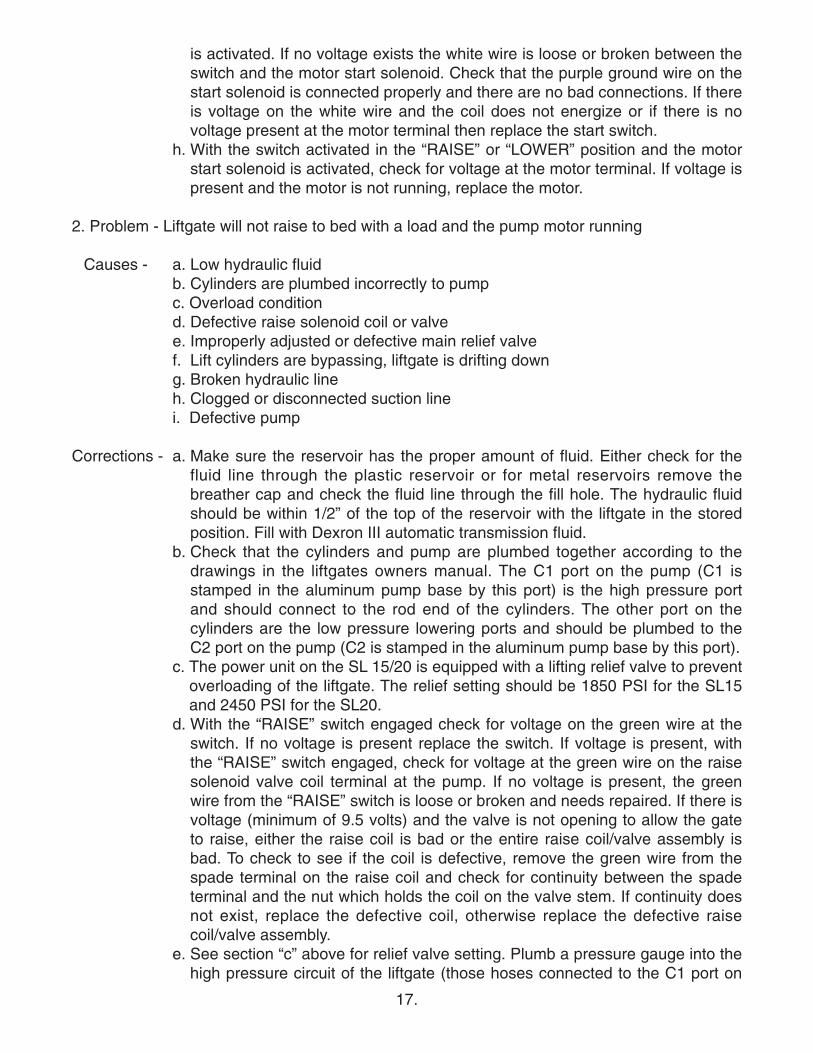
is activated. If no voltage exists the white wire is loose or broken between theswitch and the motor start solenoid. Check that the purple ground wire on thestart solenoid is connected properly and there are no bad connections. If thereis voltage on the white wire and the coil does not energize or if there is novoltage present at the motor terminal then replace the start switch.
h. With the switch activated in the “RAISE” or “LOWER” position and the motorstart solenoid is activated, check for voltage at the motor terminal. If voltage ispresent and the motor is not running, replace the motor.
2. Problem - Liftgate will not raise to bed with a load and the pump motor running
Causes - a. Low hydraulic fluidb. Cylinders are plumbed incorrectly to pumpc. Overload conditiond. Defective raise solenoid coil or valvee. Improperly adjusted or defective main relief valvef. Lift cylinders are bypassing, liftgate is drifting downg. Broken hydraulic lineh. Clogged or disconnected suction linei. Defective pump
Corrections - a. Make sure the reservoir has the proper amount of fluid. Either check for thefluid line through the plastic reservoir or for metal reservoirs remove thebreather cap and check the fluid line through the fill hole. The hydraulic fluidshould be within 1/2” of the top of the reservoir with the liftgate in the storedposition. Fill with Dexron III automatic transmission fluid.
b. Check that the cylinders and pump are plumbed together according to thedrawings in the liftgates owners manual. The C1 port on the pump (C1 isstamped in the aluminum pump base by this port) is the high pressure portand should connect to the rod end of the cylinders. The other port on thecylinders are the low pressure lowering ports and should be plumbed to theC2 port on the pump (C2 is stamped in the aluminum pump base by this port).
c. The power unit on the SL 15/20 is equipped with a lifting relief valve to preventoverloading of the liftgate. The relief setting should be 1850 PSI for the SL15and 2450 PSI for the SL20.
d. With the “RAISE” switch engaged check for voltage on the green wire at theswitch. If no voltage is present replace the switch. If voltage is present, withthe “RAISE” switch engaged, check for voltage at the green wire on the raisesolenoid valve coil terminal at the pump. If no voltage is present, the greenwire from the “RAISE” switch is loose or broken and needs repaired. If there isvoltage (minimum of 9.5 volts) and the valve is not opening to allow the gateto raise, either the raise coil is bad or the entire raise coil/valve assembly isbad. To check to see if the coil is defective, remove the green wire from thespade terminal on the raise coil and check for continuity between the spadeterminal and the nut which holds the coil on the valve stem. If continuity doesnot exist, replace the defective coil, otherwise replace the defective raisecoil/valve assembly.
e. See section “c” above for relief valve setting. Plumb a pressure gauge into thehigh pressure circuit of the liftgate (those hoses connected to the C1 port on
17.
the pump). Remove all loads from the liftgate’s platform. Engage the “RAISE”switch until the liftgate is fully raised. Keep the “RAISE” switch engaged untilthe pump bypasses through the relief valve and note the pressure on thegauge at this time. If the rated relief pressure is not present during relief,adjust the high pressure relief valve setting as necessary. There are two reliefvalves on this pump so make sure to adjust only the high pressure reliefsetting at this time. The high pressure relief is the higher one on the aluminumpump base. If the relief pressure is not attainable the relief valve must becleaned and/or replaced or the pump is defective. See part i below.
f. If the liftgate will not raise with a load on the platform but empty is raisingslowly or only partially, one or both of the cylinders may be bypassing. Tocheck for bypassing cylinders do the following. Lower the gate to the groundto relieve all pressure from the cylinders. Disconnect both cylinders from theliftarm. Press the “RAISE” switch until both cylinders are fully retracted.Disconnect the low pressure hoses from the power unit at the swivel fitting atthe C2 port at the pump. Plug the newly opened end(s) of the swivel fitting.Put the loose ends of the disconnected hoses in a container to catch any oil,which comes out during this test. Press the “RAISE” switch for 15 to 20seconds and watch for a steady stream of fluid coming out of one of thedisconnected hose ends into the container. If no steady stream of oil ispresent reconnect all hoses and press the “LOWER” switch until bothcylinders are fully extended. Disconnect the high pressure hoses from thepower unit at the swivel fitting at the C1 port at the pump. Plug the newlyopened end(s) of the swivel fitting. Put the loose ends of the disconnectedhoses in a container to catch any oil, which comes out during this test. Pressthe “LOWER” switch for 15 to 20 seconds and watch for a steady stream offluid coming out of one of the disconnected hose ends into the container.Replace or rebuild any cylinder with fluid coming out of its disconnected hoseend, as this indicates fluid is bypassing the piston seals on the cylinder.Reconnect rebuilt or replaced cylinders and hoses as before.
g. Broken or punctured hydraulic lines and fittings must be replaced with care toavoid injury from high pressure oil streams.
h. With the liftgate at the ground, disconnect the power unit and remove thereservoir. Check to see if the suction tube is clogged or has fallen out of thepump base. Clean the screen or reattach the suction tube as required.
i. If all else fails replace the power unit, it is probably worn out.
3. Problem - Liftgate will not lower with the pump motor running
Causes - a. Defective lowering solenoid coil or valveb. Clogged or defective hydraulic lines, fittings or flow controls
Corrections - a. With the “LOWER” switch engaged check for voltage on the red wire at theswitch. If no voltage is present replace the switch. If voltage is present, withthe “LOWER” switch engaged, check for voltage at the red wire on the lowersolenoid valve coil terminal. If no voltage is present, the red wire from the“LOWER” switch is loose or broken and needs replaced. If there is voltage(minimum of 9.5 volts) and the valve is not opening to allow the gate to lower,either the lower coil is bad or the entire lower coil/valve assembly is bad. To
18.
19.
check to see if the coil is defective, remove the red wire from the spadeterminal on the lower coil and check for continuity between the spade terminaland the nut, which holds the coil on the valve stem. If continuity does notexist, replace the defective coil, otherwise replace the defective lowercoil/valve assembly.
b. Remove any obstruction in the hoses, fittings or flow controls or replace anyhose, fitting or flow control, which does not allow fluid to flow through freely.
4. Problem - Liftgate raises slowly - The raise speed of the SL15/20 on a 54” bed height whileempty at 70° F is approximately 6-8 seconds. The raise speed loaded for thesame conditions is approximately 13-16 seconds.
Causes - a. Overload condition b. Cold weatherc. Partially blocked suction screen d. Lift cylinders are bypassinge. Improperly adjusted or defective raise relief valvef. Low voltage and/or bad groundg. Worn out pump
Corrections - a. See section 2cb. Refer to Owner’s Manual for alternative oils to use for cold weather
conditions.c. Remove reservoir and clean or replace suction screen as necessary.d. See section 2fe. See section 2ef. The minimum voltage between the motor stud and ground is 9.5 volts at
maximum load conditions. See section 1b and 1c. g. After all other corrections are performed it will be necessary to replace the
pump.
5. Problem - Foamy oil flowing from reservoir breather
Causes - a. Air is present in the system
Corrections - a. This can occur if the motor is not running as the liftgate is lowered. Seeproblem 1, part e and f. Also air can enter the system if the fluid level is low,see problem 2, part a, or if the suction tube is disconnected, see problem 2,part h. Also air may enter through fittings, which are not tightened properly, socheck for any leaks around fittings or hoses. Once the source of the air isdetermined, the cylinders must be bled of all air. Most air can be removedfrom the system by lowering the gate to the ground to relieve all pressure fromthe cylinders, unpinning the cylinders and cycling them back and forth severaltimes from fully extended to fully retracted and allowing the pump to bypassthrough the relief valves for a few seconds in each direction.
If you have any questions or problems that are not covered in this guide please call Thieman’sEngineering Department at 1-800-524-5210.

Rev. 7/10 • 2.5C • MP70380


![Introduccion a La Biotecnologia [Thieman Palladino]](https://static.fdocuments.us/doc/165x107/563db9c3550346aa9a9fafa7/introduccion-a-la-biotecnologia-thieman-palladino.jpg)