Plastic folding rule Wooden folding rule Aluminium folding ...

Tailgates By THIEMAN
SL15/20-6 AND SL15/20-10OWNERS MANUAL/PARTS LIST
IMPORTANT! KEEP IN VEHICLE!!PLEASE READ AND UNDERSTAND THE CONTENTS OF THIS
MANUAL BEFORE OPERATING THE EQUIPMENT.
TAILGATES, INC.600 East Wayne Street
Celina, Ohio 45822Phone: 419-586-7727 Fax: 419-586-9724
HIEMANNATIONAL TRUCK EQUIPMENT ASSOCIATION
Member
STOWAWAY®SIDELLOOAADDEERR

TABLE OF CONTENTS
PARTS ORDERING PROCEDURE . . . . . . . . . . . . . . . . . . . . . . . . . . 2
WARNINGS . . . . . . . . . . . . . . . . . . . . . . . . . . . . . . . . . . . . . . . . . . . . 3
OPERATING INSTRUCTIONS. . . . . . . . . . . . . . . . . . . . . . . . . . . . . . 4
MAINTENANCE GUIDE. . . . . . . . . . . . . . . . . . . . . . . . . . . . . . . . . . . 5
SEMI-ANNUAL INSPECTION . . . . . . . . . . . . . . . . . . . . . . . . . . . . . . 6
ELECTRICAL PICTORIALS . . . . . . . . . . . . . . . . . . . . . . . . . . . . . . . . 6
INSPECTION AND LOCATION OF DECALS. . . . . . . . . . . . . . . . . . . 7
PLATFORM ASM . . . . . . . . . . . . . . . . . . . . . . . . . . . . . . . . . . . . . . . . 8
PUMP ASM -TOGGLE CONTROL. . . . . . . . . . . . . . . . . . . . . . . . . . . 9
TRUNNION, LIFT ARM, AND IDLER ARM ASM-10”. . . . . . . . . . 10,11
TRUNNION, LIFT ARM, AND IDLER ARM ASM-6”. . . . . . . . . . . 12,13
FOR YOUR RECORDSModel No. __________________________ Date Purchased _______________________
Serial No. __________________________NOTE: WHEN ORDERING PARTS BE SURE TO INCLUDE THIS INFORMATION!
PARTS ORDERING PROCEDURE
When ordering parts, please include all the information asked for below. If this informationis not available, a complete written description or sketch of the required part will help Thiemanidentify and deliver the needed part to you.
THE FOLLOWING INFORMATION MUST BE INCLUDED:
1. Serial Number - Thieman liftgate serial numbers can be found on the tag located on thefront side of the trunnion tube.
2. Model Number and Capacity.3. Platform size and Material - Steel or Aluminum. 4. Part number.5. Description.6. Quantity required.
3.
WARNING!
The following list of warnings are to be read before operating the SL series liftgate.
+ Read this Owner’s Manual and all of the decals on the liftgate BEFORE operating the liftgate.+ All protective covers and guards must be in place before operating the liftgate.+ DO NOT operate the liftgate if you do not have a thorough knowledge and understanding of
the operation of the liftgate. + NEVER OVERLOAD THE LIFTGATE. The maximum rated capacity of the SL series liftgate
differs with each model as follows:SL15 - 1500lbs.SL 20 - 2000lbs.
+ Never use the liftgate if it makes any unusual noises, has vibrations, or fails to operatefreely.
+ Make certain that the area below the platform is clear before and at all times during theoperation of the liftgate.
+ Keep hands and feet clear of all pinch points.
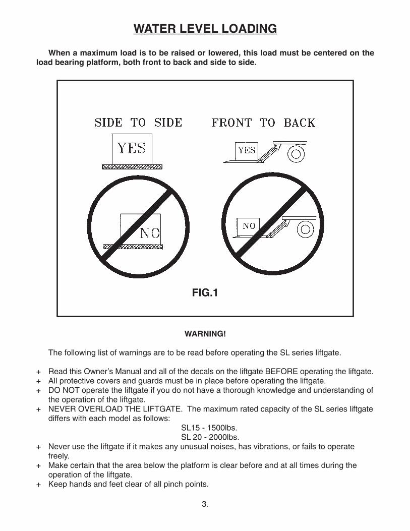
WATER LEVEL LOADING
When a maximum load is to be raised or lowered, this load must be centered on theload bearing platform, both front to back and side to side.
FIG.1

4.
+ The platform must be in the closed position and the transit chains attached properly beforetransit.
+ Always load as close to the center of the platform and as close to the vehicle as possible.See Figure 1.
+ Never operate lift trucks on or over any part of the platform.+ Load and unload the platform from the rear and not from the side of the platform.+ Only operate liftgate when vehicle is on level ground and the parking brake is set.+ Follow the maintenance guide as outlined in this manual.+ DO NOT attempt any repairs unless you are a qualified and authorized THIEMAN distributor.+ If any repairs, adjustments, or maintenance not covered in this manual are required, contact
your nearest Thieman distributor or the factory.+ DO NOT modify this liftgate. Altering this liftgate may cause serious personal injury or damage
the liftgate and will void all warranties.
OPERATING INSTRUCTIONS
CautionBe sure to operate liftgate at a safe distance and never improperly load platform as this maycause personal injury or damage to the liftgate.
UNFOLDING OF PLATFORM1. Raise platform by pushing the raise switch up until tension is removed from stow chains.2. Unhook stow chains from lift arms.3. Lower platform by pushing the lower switch until the platform is approximately 3/4 of the
way to the ground.4. Using platform handles, manually lift and pull platform until lift arms are fully extended.5. Manually unfold platform extension and ramp.
RAISING OF PLATFORM1. Push raise switch to raise platform to bed height.
LOWERING OF PLATFORM1. Push lower switch to lower platform to the ground.
CLOSING OF PLATFORM1. Raise platform approximately 6” from the ground.2. Manually fold platform extension and ramp.3. Using platform handles, manually lift and push platform into the folded position.4. Raise gate into the stowed position.5. Attach stow chains to lift arms.
5.
MAINTENANCE GUIDE
The following inspection and maintenance operations should be performed at therecommended intervals or anytime the liftgate shows signs of abuse, and improper orabnormal operation.
MONTHLY INSPECTION AND MAINTENANCE
Operate the liftgate throughout its entire operational cycle and check the following:1. Check that there are no unusual noises or vibrations.2. Check platform height relative to bed height. If platform is lower, adjust cylinder with a
13/16 wrench to obtain the necessary height.3. Check for apparent damage to the liftgate such as bent or distorted members, any cracked
welds that may have resulted from overloading or abuse.4. Check for excessive wear in the following areas:
A. Platform hinge pins and bushingsB. All cylinder pins, bolts, and bushings
5. Check that the platform pivot pins are in place and retained by their proper retainers.6. Check that all protective covers and guards are properly in place and secured.7. Check for oil leaks in these areas:
A. Lift cylinderB. Hydraulic hose – replace if it shows signs of wear or cracking.C. Hydraulic fittings – tighten or replace as may be required to stop leakage.
8. Check the oil level in the pump reservoir. With the liftgate in the stowed position the oilshould be within 1/2” from the top of the reservoir. See chart below for oil applications.
9. Check that all wiring and battery cable connections are tight and free of corrosion.10.Lubrication of the SL series liftgate should be as follows for all user conditions:
Area of Tailgate Type of Lubrication FrequencyPivot pins w/ zerk Grease+ 50 cyclesPump oil change see chart below yearly
*Most of the pivot points on the SL have special bushings that do not require lubrication.+See the parts list for the location of the grease zerks.For -40 to 120 F use #0 Grade grease.For -20 to 200 F use #1 Grade grease.
Temperature Range-20 to 130 F
-50 to 80 F
-75 to 165 F
Acceptable FluidsDexron IIIExxon Superflo ATFShell Donax TG
Shell Aero Fluid 4Mobil Aero HFAExxon Univis J-13MIL H-5606
Exxon Univis J-26
HYDRAULIC FLUID CHART

6.
Semi-Annual Inspection1. Perform the procedures outlined in the Monthly Inspection and Maintenance.2. Inspect pump motor by:
A. Disconnecting battery cableB. Remove motor end coverC. Examine the armature brushes for wear. (Brushes should be replaced if they are
less than 1/8” long.)D. Clean all residue out from inside of the motor housing.E. Apply several drops of light weight machine oil to the armature shaft bearing in the
motor end cover and reassemble the motor end cover.3. If the hydraulic oil in the reservoir is dirty:
A. Unfold platform and lower platform to the ground. Raise platform to bed height socylinders are fully retracted. Support the platform in this position with a lift truck orcrane.
B. Drain the oil from the hydraulic system and flush the entire system.C. Remove reservoir from pump and clean suction line filter. Also clean out any conta-
minants inside reservoir. Remount reservoir when completed.D. Replace the oil as outlined in Section 9 under Monthly Maintenance and Inspection.
11. Check the pump relief pressure and also the motor amperage at this pressure. Thesevalues should be as follows:Model Max Amp Draw Relief Pressure (psi)SL-15 170 1850SL-20 190 2450
ELECTRICAL PICTORIAL

7.
INSPECTION AND LOCATION OF DECALS
Item Part Name Part Number1 Warning Decal-off center 46710502 Fast Idle Decal 46501503 Danger Decal-no riding 46094 Operating Decal 46085 Capacity Decal-1500# 46500705 Capacity Decal-2000# 46501006 Warning Decal-pinch point 46047 Handle decal 46058 Wiring Decal 46149 Urgent Warning 465053010 Warning Decal-High Pressure 462011 Caution Decal 4650770
8.
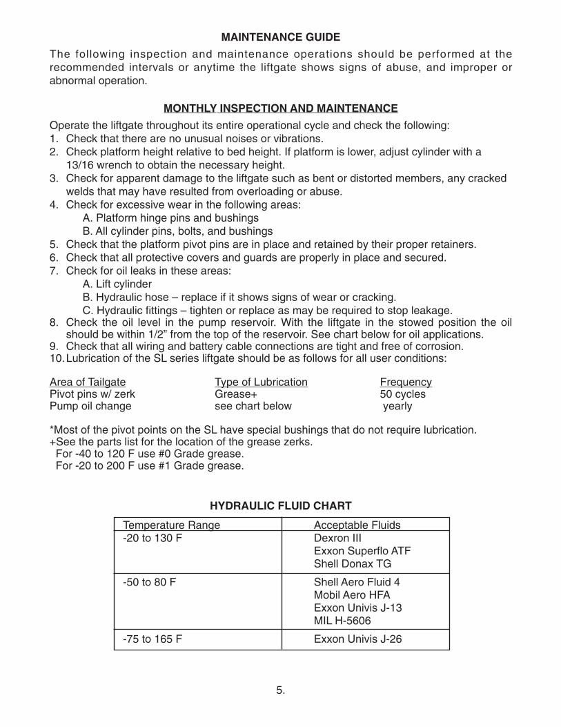
PLATFORM ASSEMBLY
Item Part Number Description Qty
1 3406 Platform Asm-incl 2 to 5 12 31023 Platform main section 1 3 31024 Platform extension 14 5056 Pin 25 5781001 Retaining ring 46 31020-002 Platform hinge RH 17 31020-001 Platform hinge LH 18 8120382 Lockwasher .38 12 9 8108-001 Screw .38-16 x 1.75 S.S. 1210 8107-011 Washer .62 2

9.
Item Part Number Description Qty
1 4404 EST Pump Asm-incl 2 to 5 12 4421420 Pump bracket 13 4420409 Breather Cap 14 4423520 Motor 8111 15 4447 Solenoid 16 4301770 Circuit Breaker-150A 17 5765 Cover 18 5700100 Strap 19 4900000 .25 Swivel elbow 410 4965020 Hose 51.00 211 4900540 Restrictor elbow 212 4318-002 Battery Cable #2x2’ 113 5781008 Retaining ring 414 5009 Pin 215 31061 Cylinder 3 x 6 216 4300030 Battery cable #2 x 25’ 117 4350 Cable lug 118 5701260 Cable retainer 419 8180126 Screw .38-16 x 1.50 520 8106-010 Internal Tooth Lockwasher .38 1021 8120377 Nut .38 522 8120388 Flatwasher .38 423 5702360 Toggle cup 124 4301740 Toggle switch 125 4965015 Hose 84.00 226 4900290 Dual Swivel Elbow 227 5702371 Spring pin 228 5024 Pin 229 4319-001 Heat Shrink 130 4301750 Toggle Seal 131 5793010 Self Tap Screw .25 x .75 332 4422860 Pushbutton control 133 31057 Pump Mtg. Bracket 134 4318-002 Ground Cable #2 x 2' 135 8104-006 Screw .31 x 1 1
PUMP ASSEMBLY

10.

11.
Item Part Number Description Qty
1 31046 Trunnion asm 12 31028 Lift arm asm 13 5781015 Retaining ring 44 8107-010 Flatwasher 1.00 45 2125 Lower folding link 26 31022 Folding link 27 31059 Idler arm 28 3110-002 Strap weld RH 19 3110-001 Strap weld LH 110 5019 Adjustment rod 211 31374 Clevis LH thread 212 31373 Clevis RH thread 213 5101120 Spring 214 5507-001 Bronze Bushing 215 3103751 Chain Asm 216 5708-001 Spring pin 417 5781008 Retaining ring 1618 4100340 Chain Link 219 4100354 Chain-One Links 220 31211 Link Weld 221 9413534 Locknut .38 222 5793002 Screw .38 x 1.25 223 8107-008 Flatwasher 1.00 424 8271291 Zerk 825 31284-001 Leveling strap LH 126 31284-002 Leveling strap RH 127 5009 Pin 228 5024 Pin 229 8121222 Cotter Pin 430 5018 Pin 231 5504-001 Bushing 832 5504-005 Bushing 1233 9429664 Flatwasher .75 234 5702371 Spring pin 435 5017 Pin 236 8120396 Flatwasher .50 437 4220240 Insert 438 8181635 Screw .38-24 x .75 439 2037000 4 x 6 x .38 angle 2
TRUNNION, LIFT ARM, & IDLER ARM ASM-10”
12.
13.
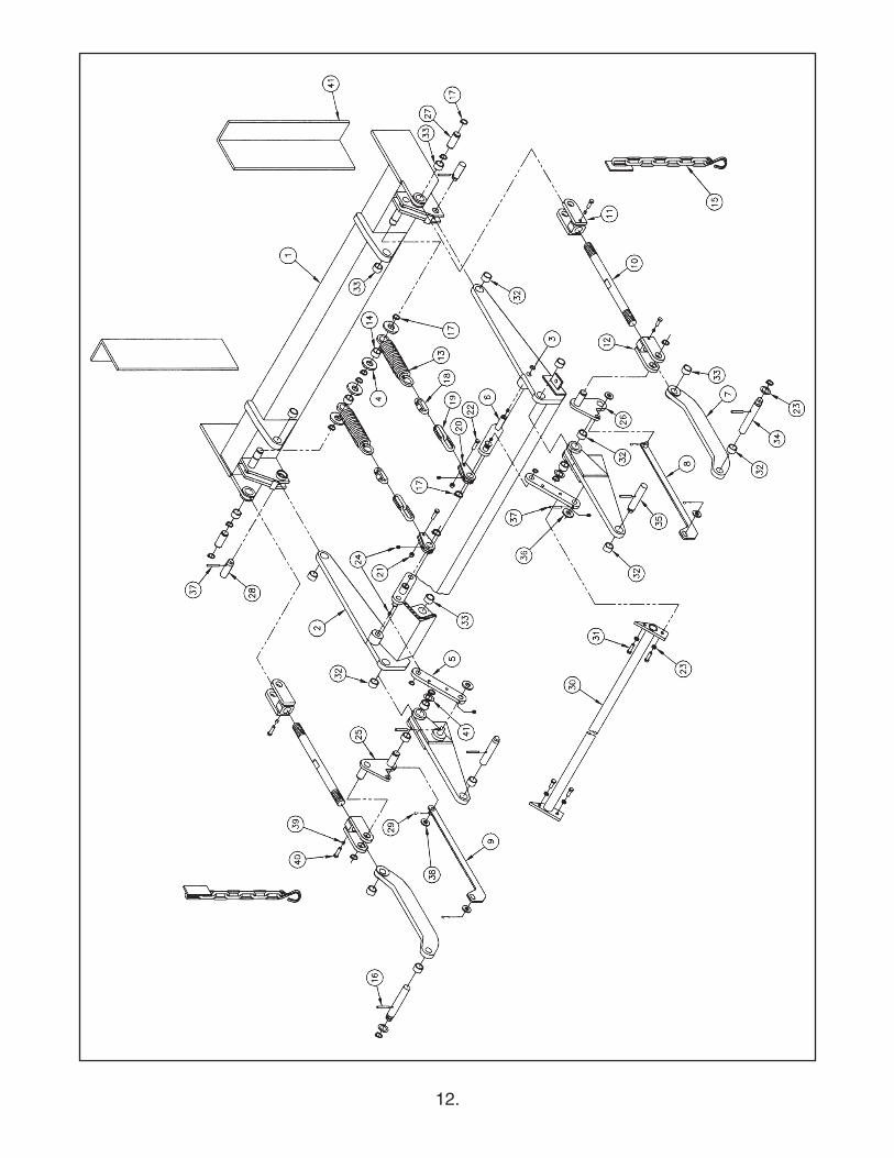
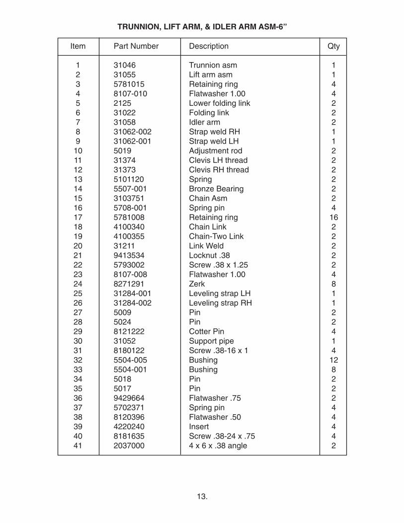
Item Part Number Description Qty
1 31046 Trunnion asm 12 31055 Lift arm asm 13 5781015 Retaining ring 44 8107-010 Flatwasher 1.00 45 2125 Lower folding link 26 31022 Folding link 27 31058 Idler arm 28 31062-002 Strap weld RH 19 31062-001 Strap weld LH 110 5019 Adjustment rod 211 31374 Clevis LH thread 212 31373 Clevis RH thread 213 5101120 Spring 214 5507-001 Bronze Bearing 215 3103751 Chain Asm 216 5708-001 Spring pin 417 5781008 Retaining ring 1618 4100340 Chain Link 219 4100355 Chain-Two Link 220 31211 Link Weld 221 9413534 Locknut .38 222 5793002 Screw .38 x 1.25 223 8107-008 Flatwasher 1.00 424 8271291 Zerk 825 31284-001 Leveling strap LH 126 31284-002 Leveling strap RH 127 5009 Pin 228 5024 Pin 229 8121222 Cotter Pin 430 31052 Support pipe 131 8180122 Screw .38-16 x 1 432 5504-005 Bushing 1233 5504-001 Bushing 834 5018 Pin 235 5017 Pin 236 9429664 Flatwasher .75 237 5702371 Spring pin 438 8120396 Flatwasher .50 439 4220240 Insert 4 40 8181635 Screw .38-24 x .75 441 2037000 4 x 6 x .38 angle 2
TRUNNION, LIFT ARM, & IDLER ARM ASM-6”


10/03 • 2.5C • MP53374