SI unit for EtherNet/IP - SMC ETechcontent2.smcetech.com/pdf/si/si_manuals/EX250-SEN1_e.pdf · SI...
37
No.EX##-OMK0004 SI unit for EtherNet/IP PRODUCT NAME EX250-SEN1 Model / Series
Transcript of SI unit for EtherNet/IP - SMC ETechcontent2.smcetech.com/pdf/si/si_manuals/EX250-SEN1_e.pdf · SI...

No.EX##-OMK0004
SI unit for EtherNet/IP
PRODUCT NAME
EX250-SEN1 Model / Series

No.EX##-OMK0004
Table of Contents
Safety Instruction 2 Product Summary 6 SI Unit Model Indication Method 7 Part Names 7 Dimensions 8
Mounting/Installation 8 Specifications 11 Wiring 12 Display/Setting 14 EtherNet/IP CONFIGURATION WITH RSLogix5000TM 16
Input Block Model Indication Method 17 Part Names 17 Dimensions 18
Mounting/Installation 18 Specifications 18 Wiring 19 Display/Setting 20
EX9 Series Output Block/Power Block Model Indication Method 21 Part Names 21 Dimensions 22
Mounting/Installation 22 Specifications 23 Wiring 23 Display 26
Option 27 Maintenance procedure 29 Troubleshooting 30
-1-

No.EX##-OMK0004
Safety Instructions This SI unit and this manual contains essential information to prevent possible injury and damage to (users and other people, and property) and to ensure correct handling. Please confirm understanding the meaning of the following messages (signs) before reading the remaining the text, and always follow the instructions. Also carefully read the instruction manual for any relevant equipment or apparatus before use. Indications
IMPORTANT MESSAGES Read this manual and follow the instructions. Signal words such as WARNING, CAUTION and NOTE, will be followed by important safety information that must be carefully reviewed.
Indicates a potentially hazardous situation which could result in death or serious injury if you do not follow instructions.
Indicates a potentially hazardous situation which if not avoided, may result in minor injury or moderate injury.
NOTE Gives you helpful information.
Operator ♦This manual has been written for those who have knowledge of machinery and apparatuses
that use pneumatic equipment and have full knowledge of assembly, operation and maintenance of such equipment.
♦Please carefully read and understand this manual before assembling, operating or performing maintenance on the SI Unit.
Usage Restrictions ♦This product is designed to be used in general equipment for factory automation. Never use this
product with equipment or apparatus that directly concerns human lives*1, or in which a malfunction or failure can cause a great loss. *1:Equipment or apparatus that directly concerns human lives refers to the following: •Medical equipment such as life support systems or equipment used in operating rooms •Compulsory equipment required by law such as the Fire Prevention Law, Construction Law and etc. •Equipment or apparatus that conforms with those mentioned above.
♦Contact our sales department when plans are made for the product to be used for the system*2 including equipment that concerns itself with the safety of persons or that seriously affects the public. Such usage requires special consideration*3. *2:A system or equipment that concerns itself with the safety of persons or that seriously affects
the public refers to the following: •Nuclear reactor control systems in a nuclear power plants, safety protection systems or other systems important for safety in nuclear power facility •Driving control system for a mass transportation system, and flight control systems •Equipment or apparatuses that comes in contact with foods or beverages
*3:Special consideration refer to discussing usage with our engineers to establish a safe system designed as fool-proof, fail-safe, redundant and etc.
♦Special consideration*4 should be taken regarding safety or maintainability to prevent a failure or malfunction which can cause a hazard or less. That is likely to occur under certain environmental stress (deterioration). *4:Special consideration means to fully review the equipment or apparatus in design stage and
to establish a back up system in advance, such as a redundant system or fail-safe system.
-2-
No.EX##-OMK0004
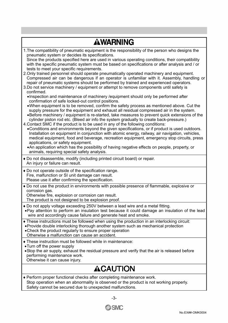
1.The compatibility of pneumatic equipment is the responsibility of the person who designs the
pneumatic system or decides its specifications. Since the products specified here are used in various operating conditions, their compatibility with the specific pneumatic system must be based on specifications or after analysis and / or tests to meet your specific requirements.
2.Only trained personnel should operate pneumatically operated machinery and equipment. Compressed air can be dangerous if an operator is unfamiliar with it. Assembly, handling or repair of pneumatic systems should be performed by trained and experienced operators.
3.Do not service machinery / equipment or attempt to remove components until safety is confirmed. •Inspection and maintenance of machinery /equipment should only be performed after confirmation of safe locked-out control positions. •When equipment is to be removed, confirm the safety process as mentioned above. Cut the supply pressure for the equipment and exhaust all residual compressed air in the system. •Before machinery / equipment is re-started, take measures to prevent quick extensions of the cylinder piston rod etc. (Bleed air info the system gradually to create back-pressure.)
4.Contact SMC if the product is to be used in any of the following conditions: •Conditions and environments beyond the given specifications, or if product is used outdoors. Installation on equipment in conjunction with atomic energy, railway, air navigation, vehicles, medical equipment, food and beverage, recreation equipment, emergency stop circuits, press applications, or safety equipment. •An application which has the possibility of having negative effects on people, property, or animals, requiring special safety analysis.
♦Do not disassemble, modify (including printed circuit board) or repair. An injury or failure can result.
♦Do not operate outside of the specification range. Fire, malfunction or SI unit damage can result. Please use it after confirming the specification.
♦Do not use the product in environments with possible presence of flammable, explosive or corrosion gas. Otherwise fire, explosion or corrosion can result. The product is not designed to be explosion proof.
♦Do not apply voltage exceeding 250V between a lead wire and a metal fitting. •Pay attention to perform an insulation test because it could damage an insulation of the lead
wire and accordingly cause failure and generate heat and smoke. ♦These instructions must be followed when using the production in an interlocking circuit: •Provide double interlocking thorough another system such as mechanical protection •Check the product regularly to ensure proper operation Otherwise a malfunction can cause an accident.
♦These instruction must be followed while in maintenance: •Turn off the power supply •Stop the air supply, exhaust the residual pressure and verify that the air is released before performing maintenance work. Otherwise it can cause injury.
♦Perform proper functional checks after completing maintenance work.
Stop operation when an abnormality is observed or the product is not working properly. Safety cannot be secured due to unexpected malfunctions.
-3-

No.EX##-OMK0004
NOTE ♦Follow the instructions given below when handling reduced-wiring system:
Or it will have a risk of being damaged and operating failure. ♦The instructions on selection (installation, wiring, environment of use, adjustment, operation and
maintenance) described below must also be followed. ∗Product specifications •The direct-current power supply to combine should be UL authorization power supply. (1)Limited voltage current circuit in accordance with UL508
A circuit which power is supplied by secondary coil of a transformer that meets the following conditions
. Maximum voltage (with no load) : less than 30Vrms (42.4V peak)
. Maximum current : (1) less than 8A(including when short circuited) (2) limited by circuit protector (such as fuse) with the following ratings
No load voltage (V peak) Max. current rating (A) 0 to 20 [V] 5.0
Above 20 to 30 [V] 100 / peak voltage (2)A circuit using max. 30Vrms or less (42.4V peak), which power is supplied by Class-2 power
supply unit in accordance with UL1310 or UL1585 •Operate reduced-wiring system with the specified voltage. Operation with a voltage beyond specifications could cause malfunction or damage of the unit. •Reserve a space for maintenance Be sure to keep a space for maintenance when designing layout of the unit. •Do not remove nameplate. Otherwise maintenance error and misreading of an operation manual could cause damage or malfunction. It may also result in nonconformity to safety standards.
♦Precautions on handling ∗Installation •Do not drop, hit or apply excessive shock to the unit. Otherwise the unit could be damaged so much as to result in. •Follow the specified tightening torque. Excessive tightening torque can break screws. The screw should be tighten with the specified torque, otherwise IP40 protection can not be guaranteed.
∗Wiring (including plugging in/out of connector) •Do not bend the cables or apply excessive force to them by pulling or placing heavy load. Wiring subject to bending or tensile stress could cause the cables to break. •Connect wires and cables correctly. Incorrect could wiring break the reduced-wiring system to its extent. •Do not connect wires while the power is supplied. Otherwise it can break the reduced-wiring system or I/O devices could be damaged or malfunction. •Do not connect power cable or high-voltage cable in the same wiring route as the unit. Otherwise the wires to the reduced-wiring system can be interrupted with noise or induced surge voltage from power lines or high-voltage lines and malfunction could be caused. Separate wiring of the unit and each I/O device from that of power line and high voltage line.
-4-

No.EX##-OMK0004
•Verify the insulation of wiring. Insulation failure (interference with other circuit, poor insulation between terminals and etc.) could introduce excessive voltage or current to the reduced-wiring system or each I/O device and damage them. •Separate power line for solenoid valves from power line for input and control unit. Otherwise wires can be interrupted with noise or induced surge voltage causing malfunction. •Take proper measurements such as noise filter against noise when the reduced-wiring system is incorporated in equipment or devices. Otherwise contamination with noise can cause malfunction.
∗Environment •Select an operation environment according to enclosure. (IP40) •Take sufficient shielding measures when the unit is installed. Insufficient measures could cause malfunction or failure. Verify the effect of the measures after incorporation of the unit in equipment or devices: (1) A place where noise due to static electricity is generated (2) A place where electric field strength is high (3) A place where there is radioactive irradiation (4) A place near power line •Do not use the unit near by a place where electric surge is generated. Internal circuit elements of the reduced-wiring system can deteriorate or break when equipment generating a large surge (electromagnetic lifter, high frequency induction furnace, motor, etc.) is located near the reduced-wiring system. Provide surge preventives, and avoid interference with line for the equipment. •Use the reduced-wiring system equipped with surge absorber when a surge-generating load such as solenoid valve is driven directly. Direct drive of a load generating surge voltage can damage reduced wiring system. •Prevent foreign matter such as remnant of wires from entering the unit. Take proper measures for the remnant not to enter the reduced-wiring system in order to prevent failure or malfunction. •Do not expose the reduced-wiring system to vibration and impact. Otherwise failure or malfunction could be caused. •Keep the specified ambient temperature range. Otherwise malfunction could be caused. Do not use reduced-wiring system in a place where temperature suddenly changes even within the specified range. •Do not expose the reduced-wiring system to heat radiation from a heat source located nearby. Malfunction could be caused.
∗Adjustment and Operation •Use precision screwdriver with for small flat blade for setting Dip switch. ∗Maintenance •Perform maintenance and check regularly. Otherwise an unexpected malfunction of components could of the unit occur due to a malfunction of the whole unit. •Perform a proper functional check. Stop operation when an abnormality is observed such that the device doesn't work properly. Otherwise an unexpected malfunction of the unit component can occur. •Do not use solvents such as benzene, thinner or other to clean the reduced-wiring system. They could damage the surface of the body and erase the indication on the body. Use a soft cloth to remove stains. For heavy stains, use a cloth soaked with diluted neutral detergent and fully squeezed, then wipe up the stains again with a dry cloth.
-5-

No.EX##-OMK0004
Product summary System configuration general
This system realizes reduced wiring between the input and output equipment by connecting to EtherNet/IP. EtherNet/IP and the input and output equipment communicates through the SI Unit. Up to 32 Inputs can be connected to the SI Unit using Input Blocks. Up to 32 Outputs Note) from combined EX9 Output Blocks and Valve manifolds can be connected to the SI Unit. Note) The maximum output point is 24 when the Power Block is connected. Terms definition
Terms Definition DHCP A protocol to automatically set the information to be registered in individual
equipment connected with a TCP/IP network in order to use the network. This includes the IP address.
EtherNet/IP Open fieldbus for factory automation. This is a protocol that integrates the DeviceNet communication protocol (CIP: Common Industrial Protocol) into EtherNet or TCP/IP. Currently, it is popular in the US and is spreading to Europe.
IP address A 32 bit sequence of numbers assigned to identify individual devices connected to a network. All devices connected to the network are given individual IP addresses.
MAC address A number unique to each device connected to EtherNet. MS Abbreviation of “module status”. It shows whether the power supply of SI unit is
turned on and the normal operation is available. NS Abbreviation of “network status”. It shows the status of EtherNet/IP
communication. SI unit An abbreviation of serial interface. It sends and receives data by bit through a
couple of signal lines, convert it to parallel and correspondingly control connected load. (A serial-to parallel converting unit.)
Half duplex Communication method by sending and receiving alternately for bilateral communication.
Full duplex Communication method by sending and receiving simultaneously for bilateral communication.
100BASE-TX Standard of LAN transmission route with a transmission speed of 100Mbps.
-6-

No.EX##-OMK0004
SI Unit Model Indication Method
Part Names
No. Part names Application 1 Communication connector Connect with EtherNet/IP line. Note1) 2 Power supply connector Supplies power to the solenoid valve, the Output Block, SI Unit and the
Input Block. Note1) 3 Input Block connector Connects the Input Block. 4 Output Block connector Connects the solenoid valve, Output Block and etc. 5 Display LED display shows the SI Unit status. Note2) 6 Switch protective cover Display the power supply status and communication status with PLC.
Note2) 7 Ground terminal Used for grounding. 8 MAC address A unique MAC address of 12 hexadecimal number digits to each SI
Unit. Note1 : For wiring method, refer to subsection "Wiring" (page 12) in this Technical Specification. Note2 : For display and setting method, refer to subsection "Display/Setting" (page 14) in this Technical
Specification.
-7-
No.EX##-OMK0004
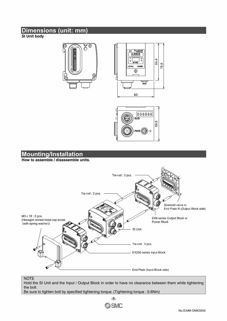
Dimensions (unit: mm) SI Unit body
Mounting/Installation How to assemble / disassemble units.
NOTE Hold the SI Unit and the Input / Output Block in order to have no clearance between them while tightening the bolt. Be sure to tighten bolt by specified tightening torque. (Tightening torque : 0.6Nm)
-8-
No.EX##-OMK0004
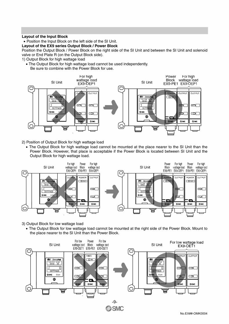
Layout of the Input Block • Position the Input Block on the left side of the SI Unit. Layout of the EX9 series Output Block / Power Block Position the Output Block / Power Block on the right side of the SI Unit and between the SI Unit and solenoid valve or End Plate R (on the Output Block side). 1) Output Block for high wattage load • The Output Block for high wattage load cannot be used independently.
Be sure to combine with the Power Block for use.
2) Position of Output Block for high wattage load • The Output Block for high wattage load cannot be mounted at the place nearer to the SI Unit than the
Power Block. However, that place is acceptable if the Power Block is located between SI Unit and the Output Block for high wattage load.
3) Output Block for low wattage load • The Output Block for low wattage load cannot be mounted at the right side of the Power Block. Mount to
the place nearer to the SI Unit than the Power Block.
-9-

No.EX##-OMK0004
Position of End Plate • Be sure to connect the End Plate (on the Input Block side) at the left end of the manifold. • When the valve is not connected, be sure to connect the End Plate R (on the Output Block side) at the right
end of the manifold. Installation example Dimensions with solenoid valves unconnected [Unit: mm]
1 2 3 4 5 6 7 8 9 10 L 114 135 156 177 198 219 240 261 282 303
[mm] * Each dimension shows the unit without solenoid valves connected and with an End Plate R (on the Output Block side) connected. Standard settings of L dimensions are with 10 or less m blocks. Ask SMC sales for the setting with over 10 blocks mounted. Refer to the individual specifications for the dimensions when the solenoid valves are connected.
-10-
L m

No.EX##-OMK0004
Specifications Basic specifications Rated voltage 24VDC Range of power supply voltage
Power supply for input and control : 24VDC±10% Power supply for output : 24VDC+10%/-5%
Rated current Power supply for input and control : Max. 1.1A Inside SI Unit : 0.1A
Input device :1A Power supply for output : Max. 2A
Number of input/output points
Input point : Max. 32/Output point : Max. 32 *
Output type PNP output (-COM.) * The maximum output point is 24 when the Power Block is connected.
Higher-level bus Protocol Ethernet (IEEE802.3)
Media 100BASE-TX Communication speed 10M/100Mbps (Automatic selection or manual setting) Max. segment length 100m (328ft) Max. transceiver number
2 (per segment)
Communication method
Full duplex/Half duplex (automatic selection or manual setting)
Fieldbus protocol EtherNet/IPTM I/O message Input : Data length 6 byte, Instance 100.
Output : Data length 4 byte, Instance 150. IP address setting range 192.168.0.1 to 192.168.0.14 (Setting by an internal switch)
Or optional setting by the DHCP server Device information Vendor ID : 7 (SMC Corp.)
Product type : 12 (communication adapter) Product code : 107
I/O mapping Input area mapping
Input data MSB LSB MSB LSB
Offset (word)
15 8 7 0 0 15 14 13 12 11 10 9 8 7 6 5 4 3 2 1 0 1 31 30 29 28 27 26 25 24 23 22 21 20 19 18 17 16 2 L L L L SP DI L L L L L L L L L L
L : Fixed to Low Diagnostic (Status input area)
Item Status Condition 0 No supply voltage SP Solenoid power supply status 1 Supply voltage OK 0 Short circuit DI Status of sensor power supply 1 Normal
Output area mapping
Output data MSB LSB MSB LSB
Offset (word)
15 8 7 0 0 15 14 13 12 11 10 9 8 7 6 5 4 3 2 1 0 1 31 30 29 28 27 26 25 24 23 22 21 20 19 18 17 16
-11-
Status input area
Sensor input area

No.EX##-OMK0004
Wiring 1. Communication wiring
Connect the Ethernet Communication Cable to the communication connector of SI Unit. Cable connection 1) Aligning the key groove with the communication connector (4-pin, socket) of SI Unit, plug the Ethernet
Communication Cable (plug). 2) Tighten the lock nut on cable side by turning it clockwise by hand. 3) Confirm that the connector portion does not move.
Pin layout and connection diagram of Ethernet Communication Cable
Cable specifications Core wire AWG 26
Sheath color Blue green Refer to “Media Planning and Installation Manual” of ODVA for detail of Wiring.
-12-

No.EX##-OMK0004
2. Power supply wiring
Connect the Power Supply Cable to the power supply connector of SI Unit. When selecting the power supply, refer to "Precautions on handling" (page 4) in this Technical Specification.
Cable connection 1) Aligning the key groove with the power
supply connector (plug) of SI Unit, plug the Power Supply Cable (socket).
2) Tighten the lock nut on cable side by turning it clockwise by hand.
3) Confirm that the connector portion does not move.
Pin layout and connection diagram of power supply connector cable for (unit : mm)
Pin No. Cable color: Signal name 1 Brown : 24VDC +10%/-5% (for solenoid valves/output) 2 White : 0V (for solenoid valves/output) 3 Blue : 24VDC ±10% (for input and control) 4 Black : 0V (for input and control) 5 Grey : Earth
NOTE Ground the Earth terminal with the ground resistance at 100 ohm or less. Make the pin No.5 of the power supply connector ungrounded, and ground at one point.
-13-

No.EX##-OMK0004
Connecting one or two power supplies to SI Unit. Both single power supply and two power supply systems can be adopted, however, the wiring shall be made separately (for solenoid valves/output and for input and control) for either system. A. Two power supplies
B. Single power supply
Display/Setting Settings for display
Display Contents OFF The power supply for solenoids is insufficient SOL Green light ON The power supply for solenoids is normal OFF The power supply for input and control is insufficient PWR Green light ON The power supply for input and control is normal OFF The power supply for control is OFF Green light ON Operating normally Green flashing Setting error (Device has not been configured) Red flashing Recoverable internal error
MS
Red light ON Unrecoverable internal error OFF The power supply for control is OFF or IP address not set Green flashing EtherNet/IP-level communication not established Green light ON Multiple EtherNet/IP-level communications established Red flashing Multiple EtherNet/IP-level communications time out
NS
Red light ON IP address duplicated
-14-

No.EX##-OMK0004
Switch setting Open the switch protective cover and set the switches with a sharp-pointed watchmakers screwdriver etc. NOTE 1. Be sure to turn off the power before setting the switches. 2. Be sure to set these switches before use. 3. After setting the switch, close the switch protective cover and tighten the screws with the proper
tightening torque. (Tightening torque : 0.6Nm)
-15-

No.EX##-OMK0004
*1 : Remote control (SW1 Dip switches 1-4 off)
SMC's EX250 SI Unit will respond to the following Rockwell Automation BOOTP/DHCP Server commands. Enable DHCP Selecting this function will enable the EX250 SI Unit to retrieve its boot information from the BOOTP/DHCP Server. If DHCP is enabled the EX250 SI Unit will retrieve its boot information during the next power up. Disable BOOTP/DHCP Selecting this function will disable the EX250 to retrieve its boot information from the BOOTP/DHCP Server, and causes the EX250 to retain its current configuration during the next power up.
*2 : DHCP Mode (SW1 Dip switches 1-4 on) The IP address is acquired via DHCP Server. The IP address is not saved and lost if the power to the EX250 unit is cycled.
*3 : Hardware Addressing The IP address range is 192.168.0.1-192.168.0.14.
Default settings At the time of factory shipment, the product is in "Remote Control Mode" and set to "Enable DHCP".
NOTE If the stored IP address of an EX250 is not known, please go to the "DHCP Mode" section.
EtherNet/IP CONFIGURATION WITH RSLogix5000TM
When setting up the node with RSLogix5000TM, specific values must be entered for the assembly instance with regards to Input, Output and Configuration.
Please see the diagram below for a Rockwell Automation’s RSLogix5000 TM programming software example.
*PLC software RSLogix5000TM manufactured by Rockwell Automation is shown above. RSLogix5000 TM is a registered trademark of Rockwell Automation.
Connection Parameter Assembly Instance values:
Description Decimal Comm Format “Data-INT” “Data-SINT” Input 100 100 Output 150 150 Configuration 1 1
Size: Description Size
Comm Format “Data-INT” “Data-SINT” Input 3words 6bytes Output 2words 4bytes Configuration 0word 0byte
-16-
No.EX##-OMK0004
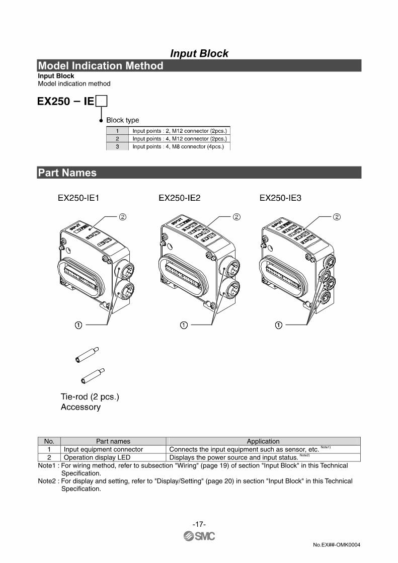
Input Block Model Indication Method Input Block Model indication method
Part Names
No. Part names Application 1 Input equipment connector Connects the input equipment such as sensor, etc. Note1) 2 Operation display LED Displays the power source and input status. Note2)
Note1 : For wiring method, refer to subsection "Wiring" (page 19) of section "Input Block" in this Technical Specification.
Note2 : For display and setting, refer to "Display/Setting" (page 20) in section "Input Block" in this Technical Specification.
-17-

No.EX##-OMK0004
Dimensions (unit: mm)
Mounting/Installation Refer to subsection "Mounting/Installation" (page 8) in this Technical Specification. Specifications Applicable sensor Current source type(PNP input)
Current sink type(NPN input) *Selected with a switch. Rated voltage 24VDC (It can have a voltage drop for 1V at max. to the power source
voltage of the SI Unit.) Logical "1" input voltage VH 11 to 30V Logical "0" input voltage VL -3 to +5V Logical "1" input current IH 8mA Typ. Connection of 2-wire sensor Possible Logical "0" input current IL Max.2.5mA Input delay time 3msec. Typ. Supply current to sensor Max. 120mA / Input Block
IE1/2 M12 connector (4 pin, plug or 5 pin, plug) Connector type of the input equipment IE3 M8 connector (3 pin, plug)
-18-

No.EX##-OMK0004
Wiring 1. Input wiring Cable wiring EX250-IE1/2/3 1) Aligning the key groove with the input
connector (socket) of Input Block, plug in the cable (plug).
2) Tighten the lock nut on cable side by turning it clockwise by hand.
3) Confirm that the connector does not move.
Input connector pin layout
EX250-IE1 (M12 connector, 5 pin, Socket)
*1) Input No.1 is connected to the pin No.2 of the input connector "0", 2 input signals can be directly input from the input connector "0".
*2) NC : Not connected
EX250-IE2 (M12 connector, 5 pin, Socket)
EX250-IE3 (M8 connector, 3 pin, Socket)
Be sure to check the specifications of the input signal when wiring the sensor. It may cause the malfunction. Mind the position of the mounting key when selecting the sensor. NOTE Mount a Waterproof Cap on each unused connector of Input Block. The proper use of Waterproof Cap can achieve IP67 Enclosure. (Tightening torque : 0.1Nm for M12) For Waterproof Cap, refer to "Option" (page 27) in this Technical Specification.
-19-

No.EX##-OMK0004
Correlation between input number and Input Block The total number of input and output blocks can not exceed 10. The maximum input point is 32.
The input number is 1, 2 ...32 from the SI Unit side. Display/Setting Display
EX250-IE1 EX250-IE2/IE3
Display Description
Lights up Power supply for sensor is ON. PWR Off Power supply for sensor is OFF. Lights up Sensor signal input corresponding to the number is ON. (Logic "1") 0, 1, 2, 3 Off Sensor signal input corresponding to the number is OFF. (Logic "0")
Switch setting • Applicable sensor to the Input Block can be switched to
NPN/PNP. • Remove the Input Block according to the
"Mounting/Installation" (page 8) in this Technical Specification, then set up the switch with a sharp-pointed watchmakers screw driver etc.
• Install the Input Block after the setting according to "Mounting/Installation" (page 8) in this Technical Specification.
-20-

No.EX##-OMK0004
EX9 Series Output Block/Power Block Model Indication Method The EX9 series General Purpose Output Block is the unit to operate various outputs (solenoid valve, relay, etc.) in combination with valve and SI Unit. There are two types ---- one type is for low wattage load (EX9-OET1) receiving power supply from SI Unit, and the other type is for high wattage load (EX9-OEP1) receiving power supply from an external source. NOTE) The type for high wattage load is used in combination with the Power Block (EX9-PE1) connected with external power supply. As the low wattage load type is powered from SI Unit, the wattage of load is limited to 1.5W NOTE) . For a load up to 12W, use the Power Block and the high wattage load type. NOTE +COM. type EX9-OET/P2 cannot be connected to EX250-SEN1.
Output Block
Power Block
Part Names Output Block
No. Part names Application 1 Output equipment connector Connects with output device. Note1) 2 Operation display LED Indicates the output status. Note2)
Note1 : For wiring method, refer to subsection "Wiring" (page 23) of section "EX9 Series Output Block/Power Block" in this Technical Specification.
Note2 : For display, refer to subsection "Display" (page 26) of section "EX9 Series Output Block/Power Block" in this Technical Specification.
-21-

No.EX##-OMK0004
Power Block
No. Part names Application
1 Power supply connector Power can be supplied to SI Unit when connecting SI Unit next to Power Block. Note1)
2 Power input connector Supplies power for output devices. Note1) 3 Operation display LED Indicates the power supply status. Note2)
Note1 : For wiring method, refer to subsection "Wiring" (page 23) of section "EX9 Series Output Block/Power Block" in this Technical Specification.
Note2 : For display, refer to subsection "Display" (page 26) of section "EX9 Series Output Block/Power Block" in this Technical Specification.
Dimensions (unit: mm) Output Block Power Block
Mounting/Installation Refer to subsection "Mounting/Installation" (page 8) in this Technical Specification.
-22-

No.EX##-OMK0004
Specifications Output Block
Model No. EX9-OET1 EX9-OEP1
Power supply type Internal power supply type External power supply type
(Supplied from the Power Block,EX9-PE1.)
Rated voltage 24VDC Output method PNP output (-COM.)
Rated load current Max. 62mA/point Max. 0.5A/point *
* It is limited to the max. Power Block supply current 3.1A. NOTE When connecting an inductive load such as a solenoid valve or relay without build-in surge suppressor, the use of an external surge suppressor is recommended.
Power Block
Power supply voltage range 24VDC+10%/-5% Output method PNP output (-COM.)
Supply current Max. 3.1A
(When it is operated with the current between 3.0A and 3.1A, the ambient temperature should be 40 deg. C or lower and the cables should not be bundled.)
Wiring 1. Output wiring Cable wiring 1) Aligning the key groove with the output connector
(socket) of Output Block, plug in the cable with connector (plug).
2) Tighten the lock nut on cable side by turning it clockwise by hand.
3) Confirm that the connector does not move. Output connector pin layout
EX9-OET1, EX9-OEP1 (M12 connector, 5 pin, Socket)
*1) Output No.1 is connected to the pin No.2 of the output connector "0", and 2 output signals can be directly output from the output connector "0".
*2) NC : Not connected
-23-

No.EX##-OMK0004
Pin layout and connection drawing of the Output Cable
Pin No Cable color: Signal name 1 Brown : NC 2 White : Output No.1/NC 3 Blue : GND 4 Black : Output No.0/Output No.1 5 Grey : NC
NOTE Mount a Waterproof Cap on each unused connector of Output Block.The proper use of Waterproof Cap can achieve IP67 Enclosure. (Tightening torque : 0.1Nm for M12) For Waterproof Cap, refer to "Option" (page 27) in this Technical Specification.
Correlation between output number and Output Block The total number of input and output blocks can not exceed 10.
The output number is 1, 2 ... from the SI Unit side.
-24-

No.EX##-OMK0004
2. Power supply wiring (Power Block)
When operating EX9-OEP1, combine it with EX9-PE1, and connect the power supply to the power input connector of EX9-PE1.
Cable wiring 1) Aligning the key groove with the connector of Power
Block, plug in the cable. 2) Tighten the lock nut on cable side by turning it clockwise
by hand. 3) Confirm that the connector does not move. EX9-PE1 pin layout
M12 connector, 5 pin, Reverse key
* It is used when power is supplied to SI Unit, using an exclusive cable from the power supply connector. When power is not supplied to the SI Unit from the Power Block, it is not required to connect the power to the pins No.3 and 4 of the power input connector.
Pin layout and connection drawing of the Power Supply Cable Power Cable (Power Block)
Pin No Cable color: Signal name 1 Brown : Power supply for output (24VDC) 2 White : Power supply for output (0V) 3 Blue : (Power supply to sensor (24VDC)) 4 Black :(Power supply to sensor (0V)) 5 Grey : Earth
-25-

No.EX##-OMK0004
Power Cable Jumper (Power Block to EX250-SEN1)
The Power Supply Cable (for Power Supply Connector of Power Block) is a bypass cable which can be used when the Power Block is positioned next to the SI Unit. NOTE Mount a Waterproof Cap on unused Power Supply Connector. The proper use of Waterproof Cap can achieve IP67 Enclosure. (Tightening torque : 0.1N⋅m for M12) For Waterproof Cap, refer to "Option" (page 27) in this Technical Specification.
Display Output Block
Display Description Lights up Output corresponding to the number is ON. 0,1
Off Output corresponding to the number is OFF.
-26-
No.EX##-OMK0004
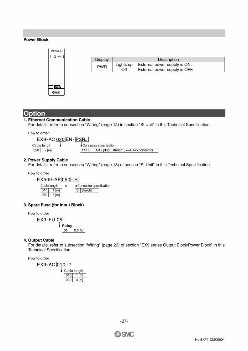
Power Block
Display Description Lights up External power supply is ON. PWR
Off External power supply is OFF.
Option 1. Ethernet Communication Cable
For details, refer to subsection "Wiring" (page 12) in section "SI Unit" in this Technical Specification.
2. Power Supply Cable
For details, refer to subsection "Wiring" (page 13) of section "SI Unit" in this Technical Specification.
3. Spare Fuse (for Input Block)
4. Output Cable
For details, refer to subsection "Wiring" (page 23) of section "EX9 series Output Block/Power Block" in this Technical Specification.
-27-

No.EX##-OMK0004
5. Power Supply Cable (for power input connector of Power Block)
For details, refer to subsection "Wiring" (page 25) of section "EX9 series Output Block/Power Block" in this Technical Specification.
6. Power Supply Cable (for power supply connector of Power Block) For details, refer to subsection "Wiring" (page 25) of section "EX9 series Output Block/Power Block" in this Technical Specification.
7. End Plate (Input Block side)
8. End Plate R (Output Block side)
-28-

No.EX##-OMK0004
9. Waterproof Cap
Mounted on the unused ports of the Input Block, Output Block and Power Block. The proper use of this Waterproof Cap can achieve IP67 Enclosure. (The Waterproof Caps are delivered together with the Power Block as accessories.)
NOTE Tighten the Waterproof Cap by the specified tightening torque. (0.05N⋅m for M8, 0.1N⋅m for M12)
Maintenance procedure
How to replace SI unit • Remove screws mounted on the endplate, and separate it from the valve unit. • Replace the SI unit (Tie rods should not be removed).
Mount the removed endplate, and tighten it with the same screws with a specified tightening torque. (0.6N⋅m)
Precautions on maintenance (1) Be sure to check that all the power supply is turned off. (2) Foreign substances shall not be intruded in the unit. (3) Foreign substances or scratches shall not be present on the gasket. (4) Screws shall be tightened with a specified tightening torque.
If they are not set properly, it will lead to board failure, or liquid and or dust might be intruded in the unit.
How to assemble and disassemble SI unit
-29-

No.EX##-OMK0004
Troubleshooting
Troubleshooting flow chart If a SI unit malfunctions, select the specific trouble with the flow chart stated below.
-30-
A reduced wiring system doesn’t
operate normally
A solenoids valve don’t operate
normally
Only the solenoid valve LED
lights on
The SI unit PWR_LED goes off
The inputs that are beyond the maximum
point number don’t operate
Refer to trouble No.1
Refer to trouble No.2
Refer to trouble No.5
Refer to trouble No.8
Refer to trouble No.9
Refer to trouble No.3
The outputs that are beyond the
maximum point number don’t operate
The input block don’t operate
normally
The Input block PWR_LED goes off.
Refer to trouble No.4
Refer to trouble No.7
The SI unit MS_LED goes off
The SI unit SOL_LED goes off
Only the solenoid valve/output block LEDs
don’t light on
Only the input signal LED of the input
block lights on Refer to
trouble No.6
Refer to trouble No.10
Refer to trouble No.11
Refer to trouble No.12
The red SI unit MS_LED lights on
The red SI unit MS_LED flashes
The green SI unit MS_LED
flashes
Refer to trouble No.13
The SI unit NS_LED goes off
Refer to trouble No.14
Refer to trouble No.15
Refer to trouble No.16
Please ask to SMC
The red SI unit NS_LED lights on
The red SI unit NS_LED flashes
The green SI unit NS_LED flashes
Yes
No

No.EX##-OMK0004
Trouble Trouble No.1
Trouble Possible cause Investigation method of cause Remedy
Only the solenoid valve LED lights on.
Solenoid valve failure. Check the troubleshooting for the solenoid valve.
Same as left.
Trouble No.2 Trouble Possible cause Investigation method of cause Remedy
The outputs that are beyond the maximum point number do not operate.
Inadequate total number of outputs from the solenoid valves and output block connected with the SI unit.
Check if the total number of outputs is 32 or less (24 for the solenoid valve VQC series).
Eliminate extra unused outputs from the manifold to ensure the number of outputs is 32 or less.
Trouble No.3 Trouble Possible cause Investigation method of cause Remedy
Check that the power supply cable for the solenoid valve and output is not broken, and that the connection between the power supply cable and connector has not loosened.
Review the connection condition of the power supply cable. (If the cable is broken, replace it with a new one.)
Incorrect wiring for the power supply for solenoid valve and the power supply for output. Check that there is no incorrect wiring of
the power supply cable.
Review the wiring condition of the power supply cable.
Failure of the power supply for the solenoid valve and output.
Check the supply voltage to the power supply for the solenoid valve and output.
Supply 24VDC +10%/-5% to the power supply for the solenoid valve and output.
Check that the bolt joining the SI unit with the solenoid valve and output block has not loosened.
Tighten the bolts by hand so that there is no gap between the SI unit and the solenoid valve and/or output block. Tighten to the specified torque. (Tightening torque: 0.6Nm)
Incorrect connection between the SI unit and the solenoid valve and/or output block.
Check if the output block (for high wattage and load and low wattage and load) and power block are mounted in the right position.
Review the position of the output block and power block.
Only the solenoid valve/output block LEDs do not light on.
Intrusion of liquids such as water.
Check that unused connectors of the output block and power block are plugged with waterproof caps.
If liquid such as water has got into the output block and/or power block, replace the output block and power block with new ones.
-31-

No.EX##-OMK0004
Trouble No.3
Trouble Possible cause Investigation method of cause Remedy
Check that the output load cable is not broken, and that the connection between the output load and connector has not loosened.
Review the connecting condition of the output load. (If the cable is broken, replace it with a new one.)
Incorrect connection of the load with the output block.
Check if the specifications of the SI unit match those of the output load (+ common, - common).
Use - common with the output load for the PNP output.
Inconsistent polarity between the solenoid valve (VQC1000/2000) and output block.
Check if the specifications of the SI unit match those of the solenoid valve and output block (+ common, - common).
Use - common with the solenoid valve and output block suitable for the PNP output of the SI unit.
Check the troubleshooting for the solenoid valve.
Same as left.
Only the solenoid valve/output block LEDs do not light on.
Failure of the solenoid valve and/or output block.
Replace the SI unit with a new one and operate to check the normal operation recovers.
Replace the SI unit with a new one.
Trouble No.4 Trouble Possible cause Investigation method of cause Remedy
The inputs that are beyond the maximum point number do not operate.
Inadequate total number of inputs from the input block connected with the SI unit.
Check if the total number of inputs is 32 or less.
Eliminate extra unused inputs from the manifold to ensure the number of inputs is 32 or less.
Trouble No.5 Trouble Possible cause Investigation method of cause Remedy
Failure of the power supply for the input and control of the SI unit.
Check the supply voltage to the power supply for the input and control of the SI unit.
Supply 24VDC ±10% to the power supply for the input and control.
Incorrect connection between the SI unit and input block.
Check that the bolt joining the SI unit and input block has not loosened.
Tighten the bolts by hand so that there is no gap between the SI unit and input block. Tighten to the specified torque. (Tightening torque: 0.6Nm)
The input block fuse has melted.
Check if the fuse of the input block has melted.
Remove the cause of the short-circuit and replace the fuse with a new one.
Intrusion of liquids such as water.
Check that unused connectors of the input block are plugged with waterproof caps.
If liquid such as water has got into the input, replace the input block with a new one.
The Input block PWR_LED goes off.
Input block failure. Replace the input block with a new one and operate to check the normal operation recovers.
Replace the input block with a new one.
-32-
No.EX##-OMK0004
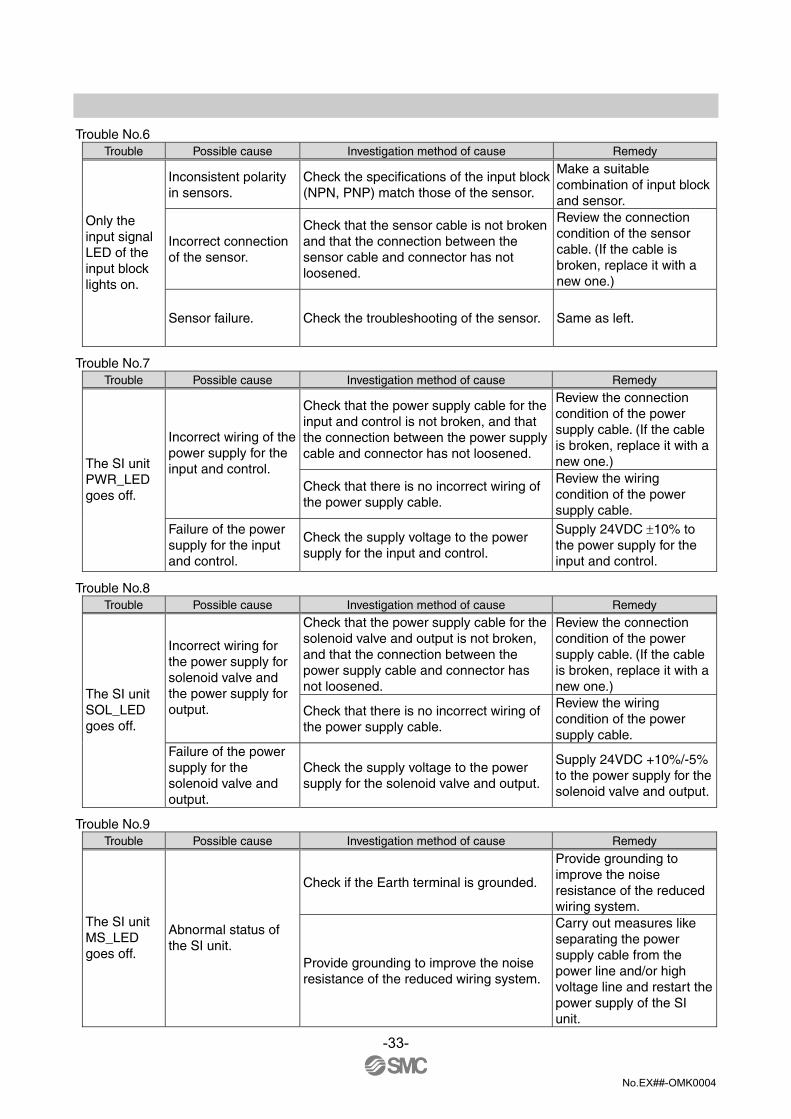
Trouble No.6
Trouble Possible cause Investigation method of cause Remedy
Inconsistent polarity in sensors.
Check the specifications of the input block (NPN, PNP) match those of the sensor.
Make a suitable combination of input block and sensor.
Incorrect connection of the sensor.
Check that the sensor cable is not broken and that the connection between the sensor cable and connector has not loosened.
Review the connection condition of the sensor cable. (If the cable is broken, replace it with a new one.)
Only the input signal LED of the input block lights on.
Sensor failure. Check the troubleshooting of the sensor. Same as left.
Trouble No.7 Trouble Possible cause Investigation method of cause Remedy
Check that the power supply cable for the input and control is not broken, and that the connection between the power supply cable and connector has not loosened.
Review the connection condition of the power supply cable. (If the cable is broken, replace it with a new one.)
Incorrect wiring of the power supply for the input and control.
Check that there is no incorrect wiring of the power supply cable.
Review the wiring condition of the power supply cable.
The SI unit PWR_LED goes off.
Failure of the power supply for the input and control.
Check the supply voltage to the power supply for the input and control.
Supply 24VDC ±10% to the power supply for the input and control.
Trouble No.8 Trouble Possible cause Investigation method of cause Remedy
Check that the power supply cable for the solenoid valve and output is not broken, and that the connection between the power supply cable and connector has not loosened.
Review the connection condition of the power supply cable. (If the cable is broken, replace it with a new one.)
Incorrect wiring for the power supply for solenoid valve and the power supply for output. Check that there is no incorrect wiring of
the power supply cable.
Review the wiring condition of the power supply cable.
The SI unit SOL_LED goes off.
Failure of the power supply for the solenoid valve and output.
Check the supply voltage to the power supply for the solenoid valve and output.
Supply 24VDC +10%/-5% to the power supply for the solenoid valve and output.
Trouble No.9 Trouble Possible cause Investigation method of cause Remedy
Check if the Earth terminal is grounded.
Provide grounding to improve the noise resistance of the reduced wiring system.
The SI unit MS_LED goes off.
Abnormal status of the SI unit.
Provide grounding to improve the noise resistance of the reduced wiring system.
Carry out measures like separating the power supply cable from the power line and/or high voltage line and restart the power supply of the SI unit.
-33-

No.EX##-OMK0004
Trouble No.10
Trouble Possible cause Investigation method of cause Remedy
Check if the Earth terminal is grounded.
Provide grounding to improve the noise resistance of the reduced wiring system.
Abnormal status of the SI unit.
Check if the power supply line is in the same route as the power line and/or high voltage line.
Separate the power supply cable from the power line and/or high voltage line.
The red SI unit MS_LED lights on.
SI unit failure. Replace the SI unit with a new one and operate to check the normal operation recovers.
Replace the SI unit with a new one.
Trouble No.11 Trouble Possible cause Investigation method of cause Remedy
Check if the Earth terminal is grounded.
Provide grounding to improve the noise resistance of the reduced wiring system.
The red SI unit MS_LED flashes.
Abnormal status of the SI unit.
Check if the power supply line is in the same route as the power line and/or high voltage line.
Separate the power supply cable from the power line and/or high voltage line.
Trouble No.12 Trouble Possible cause Investigation method of cause Remedy
The green SI unit MS_LED flashes.
Setting error. Check the setting of the SI unit. Review the setting of the SI unit.
Trouble No.13 Trouble Possible cause Investigation method of cause Remedy
The SI unit NS_LED goes off.
IP address not set. Check the setting of IP addresses. Review the setting of IP addresses.
Trouble No.14 Trouble Possible cause Investigation method of cause Remedy
The red SI unit NS_LED lights on.
Duplicated IP address.
Check that there is no duplicated IP address.
Review the setting of IP addresses.
Trouble No.15 Trouble Possible cause Investigation method of cause Remedy
Check that there is no broken communication line or loosened connector.
Review the connection condition of the communication line. (If the cable is broken, replace it with a new one.)
The red SI unit NS_LED flashes.
Broken communication line.
Check if the PLC is operating normally. Review the setting of PLC.
-34-

No.EX##-OMK0004
Trouble No.16
Trouble Possible cause Investigation method of cause Remedy
Check the address and communication setting.
Review the setting of the switch and address.
Check that there is no broken communication line or loosened connector.
Review the connection condition of the communication line. (If the cable is broken, replace it with a new one.)
The green SI unit NS_LED flashes.
Waiting for connection to be established.
Check if the PLC is operating normally. Review the setting of PLC.
-35-

No.EX##-OMK0004
Revision history
URL http://www.smcworld.com Note: Specifications are subject to change without prior notice and any obligation on the part of the manufacturer. The descriptions of products shown in this document may be used by the other companies as their trademarks. © 2006 SMC Corporation All Rights Reserved