Shure T Series Wireless User Guide English
14
Pat. Des 6,296,565 Model T Series User Guide 27C8715 (BA) 2002, Shure Incorporated Printed in U.S.A. T Series Wireless System User Guide
Transcript of Shure T Series Wireless User Guide English

Pat. Des 6,296,565
Model T Series User Guide
27C8715 (BA) 2002, Shure Incorporated
Printed in U.S.A.
T Series Wireless System User Guide
T Series Quick Set Up Guide
12
3 3
4
ÑÑÑÑ
ÑÑ
Ñ
ÑÑÑÑÑÑÑÑÑÑÑ
ÑÑÑÑÑÑÑÑÑÑ
ÑÑÑÑÑÑÑÑÑÑÑÑÑÑÑÑÑÑ
ÑÑÑÑÑ
ÑÑÑÑÑÑ
ÑÑÑÑÑÑÑ
ÑÑÑÑÑÑÑÑÑÑÑÑÑÑÑÑÑÑÑ
ÑÑÑÑÑÑÑ
ÑÑÑÑ
ÑÑÑ
ÑÑÑÑ
ÑÑÑÑ
ÑÑÑÑ
ÑÑÑÑÑ
ÑÑÑÑÑÑ ÑÑÑÑÑÑÑÑÑÑ
ÑÑÑÑ
ÑÑÑÑÑÑÑÑÑÑÑÑÑÑÑÑÑÑÑÑÑÑÑÑÑÑÑÑÑÑÑÑÑÑÑÑÑÑÑÑÑÑÑ
ÑÑÑ
5
ÑÑÑÑÑÑÑÑÑÑÑÑ
ÑÑÑÑÑÑÑÑÑÑÑÑ
ÑÑÑÑÑÑÑÑÑÑÑÑÑÑÑÑÑ
ÑÑÑÑÑÑÑÑÑÑÑÑÑÑÑÑÑÑÑÑÑ
ÑÑÑÑÑÑÑÑÑSHURE45° 45°ÑÑÑÑÑÑÑÑÑÑÑÑÑÑÑÑÑÑÑÑÑÑÑÑÑÑ
ÑÑÑÑÑÑÑÑÑÑÑÑÑÑÑÑÑÑÑÑÑÑÑÑÑÑÑÑÑÑÑÑÑÑÑÑÑ
ÑÑÑÑÑÑÑÑÑSHURE45° 45°
3
4 4
4
4 4
3ÑÑÑÑÑÑÑÑÑÑÑÑÑÑÑÑÑÑÑÑÑÑÑÑÑÑÑÑÑÑÑÑÑÑÑÑÑÑÑÑÑÑÑÑÑÑÑÑÑÑÑÑÑÑÑÑÑÑÑÑÑÑÑÑÑÑÑÑÑÑÑÑÑÑÑÑÑÑÑÑÑÑÑÑÑÑÑ
ÑÑÑÑÑÑÑÑÑÑÑÑÑÑÑÑÑ
ÑÑÑÑÑ
ÑÑÑ
ÑÑÑÑÑÑÑÑÑÑÑÑÑÑ
ÑÑÑÑÑÑÑÑÑÑÑÑÑ ÑÑÑÑÑÑÑÑÑÑÑÑÑÑÑÑÑÑÑÑÑÑÑÑÑÑÑÑÑÑÑÑÑÑÑÑÑÑÑÑÑÑÑÑÑÑÑÑÑÑÑÑÑÑÑÑÑÑÑÑÑÑÑÑÑÑÑÑÑÑÑÑÑÑÑÑÑÑÑÑÑÑÑÑÑÑÑÑÑÑÑÑÑÑÑÑÑÑ
ÑÑÑÑÑ
ÑÑÑ
ÑÑÑÑÑÑÑÑÑÑÑÑÑÑ
ÑÑÑÑÑÑÑÑÑÑÑÑÑ
ÑÑÑÑÑÑÑÑÑÑÑÑÑÑÑ
ÑÑÑÑÑÑÑÑÑÑÑÑÑÑÑÑÑÑÑÑÑÑÑÑÑÑÑÑÑÑÑÑÑÑÑÑÑÑÑÑÑÑÑÑÑÑÑÑÑÑÑÑÑÑÑÑÑÑÑÑÑÑÑÑÑÑÑ
ÑÑÑÑÑÑÑÑ ÑÑ
ÑÑÑÑÑÑÑ
1
2
T3 T4N
T3 T3T4N T4N
ÑÑÑ
ÑÑÑÑÑÑÑÑÑ
ÑÑÑÑ
ÑÑÑÑÑ
ÑÑÑÑ
ÑÑÑÑÑÑÑÑÑÑÑÑÑÑÑÑÑÑÑÑÑÑÑÑÑÑÑÑÑÑÑÑÑÑÑÑ
ÑÑ
ÑÑ
ÑÑÑÑÑÑÑÑÑÑÑÑÑÑÑÑÑÑÑÑÑÑÑÑÑÑÑ
ÑÑÑÑÑÑÑÑÑÑÑÑÑÑÑÑÑÑÑÑÑÑÑÑÑÑÑÑÑÑÑ
ÑÑÑÑÑÑÑÑÑÑÑÑ
ÑÑÑÑÑÑÑÑÑÑÑÑÑÑÑÑ
ÑÑÑÑ
ÑÑ
ÑÑÑÑÑÑÑÑÑÑÑÑÑÑÑ
ÑÑÑÑÑÑÑÑÑÑÑÑÑÑÑ
ÑÑÑÑÑÑÑÑÑÑÑÑÑÑÑ
ÑÑÑÑÑÑÑÑÑÑ
ÑÑÑÑÑÑÑÑÑÑÑÑÑÑÑÑÑÑÑÑÑÑÑÑ
ÑÑÑÑÑÑÑÑÑÑÑÑÑÑÑ
ÑÑÑÑÑÑÑÑÑÑÑÑÑÑÑ
ÑÑÑÑÑÑÑÑÑÑÑÑÑÑÑÑÑÑÑÑÑÑÑÑ
ÑÑÑÑÑÑÑÑÑÑÑÑ
ÑÑÑÑÑÑÑÑÑÑÑÑÑÑÑÑÑÑÑÑÑÑÑÑÑÑÑÑÑÑÑÑ
ÑÑÑÑÑÑÑÑÑÑÑÑÑÑÑ
ÑÑÑÑÑÑÑÑÑÑÑÑÑÑÑ
ÑÑÑÑ ÑÑÑÑÑÑÑÑÑÑÑÑÑÑÑÑÑÑÑÑÑ
ÏÏÏÏÏÏ
ÑÑÑ
ÑÑÑÑÑÑÑÑÑ
ÑÑÑÑÑ
ÑÑÑÑ
ÑÑÑÑ
ÑÑÑÑ
ÑÑÑÑÑÑÑÑÑÑÑÑÑÑÑÑÑÑÑÑÑÑÑÑÑÑÑÑÑ
Ñ
ÑÑ
ÑÑÑÑÑÑÑÑÑÑÑÑÑÑÑÑÑÑÑÑÑÑÑÑÑÑ
ÑÑÑÑÑÑÑÑÑÑÑÑÑÑÑÑÑ
ÑÑÑÑÑÑÑÑÑÑÑÑ
ÑÑÑÑÑÑÑÑÑÑÑÑÑ
ÑÑÑÑÑÑÑÑÑÑÑÑÑÑÑ
ÑÑÑÑ
ÑÑ
ÑÑÑÑÑÑÑÑÑÑÑÑÑÑÑ
ÑÑÑÑÑÑÑÑÑÑÑÑÑÑÑ
ÑÑÑÑÑÑÑÑÑÑÑÑÑÑÑÑÑÑÑÑ
ÑÑÑÑÑÑÑÑÑ
ÑÑÑÑÑÑÑÑÑÑÑÑÑÑÑÑÑÑÑÑÑÑÑÑÑÑÑ
ÑÑÑ
ÑÑÑÑÑÑÑÑÑÑÑÑÑÑÑÑÑÑÑÑÑ
ÑÑÑÑÑÑÑÑÑÑÑÑ
ÑÑÑÑÑÑÑÑÑÑÑÑ
ÑÑÑÑÑÑÑÑÑÑÑÑ
ÑÑÑÑÑÑ
ÑÑÑÑÑÑÑÑ
ÑÑÑÑÑÑÑÑÑÑÑÑ
ÑÑÑÑÑÑÑÑÑÑÑÑ
ÑÑÑÑÑÑÑÑÑÑÑÑ
ÑÑÑÑÑÑÑÑÑÑÑÑ
ÑÑÑÑÑÑÑÑÑÑÑÑÑÑÑ
ÑÑÑÑ
ÑÑÑÑ
ÏÏÏ
ÏÏÏÏÏÏÏÏÏÏÏÏ
ÏÏÏÏÏÏÏÏÏÏÏÏ
T1G
T1
1
2
3
4
5
6

SHURE Incorporated Web Address: http://www.shure.com222 Hartrey Avenue, Evanston, IL 60202–3696, U.S.A.Phone: 847-866–2200 Fax: 847-866-2279In Europe, Phone: 49-7131-72140 Fax: 49-7131-721414In Asia, Phone: 852-2893-4290 Fax: 852-2893-4055Elsewhere, Phone: 847-866–2200 Fax: 847-866-2585
8
ÈÈÈ
Í
Ñ
SH
UR
E
Ñ
SH
UR
E
ÑÑÑÑÑÑÑÑÑÑÑÑÑÑÑÑÑÑÑÑÑÑÑÑÑÑÑÑÑÑÑÑÑÑÑÑÑÑÑÑÑÑÑÑÑÑÑÑÑÑÑÑÑÑÑÑÑÑÑÑ ÑÑÑÑÑÑÑÑÑÑÑÑÑÑÑÑÑÑÑ
ÑÑÑÑÑÑÑÑÑÑÑÑÑÑÑ
8
T11
ÑÑÑÑÑÑÑÑ
ÑÑÑÑÑÑÑÑÑÑÑÑÑÑÑ
ÑÑÑÑÑ
ÑÑÑÑÑÑÑÑÑÑÑÑÑÑÑ
ÑÑÑÑÑÑÑÑÑÑ
ÑÑÑÑÑÑÑÑÑÑÑÑÑÑÑÑÑÑ
T2ÑÑÑÑÑÑÑ
ÑÑÑÑÑÑÑÑÑÑÑ
ÑÑ
ÑÑÑÑÑ
ÑÑÑÑÑÑÑ
T1/T1G
GAIN
GAIN
ÑÑÑÑÑÑÑÑÑÑÑÑÑÑ
ÑÑÑÑÑÑÑÑÑÑÑ
ÑÑÑÑÑÑÑÑÑÑÑÑÑÑÑÑÑ
ÑÑÑÑÑÑÑÑÑÑÑÑÑÑÑÑÑÑÑÑÑÑ
ÑÑÑÑÑÑÑÑSHURE
ÑÑÑÑÑÑÑÑÑÑÑÑÑÑÑÑÑÑÑÑÑÑÑÑÑÑÑÑÑÑÑÑÑÑÑÑÑÑÑÑÑÑÑÑÑÑÑÑÑÑÑÑÑÑÑÑÑÑÑÑÑÑÑÑÑÑÑÑÑÑÑÑÑÑÑÑÑÑÑÑÑÑÑÑÑÑÑÑÑ
ÑÑÑÑÑ
ÑÑÑ
ÑÑÑÑÑÑÑÑÑÑÑÑÑÑ
ÑÑÑÑÑÑÑÑÑÑÑÑÑ
9
9
ÑÑÑÑÑÑÑÑÑÑÑÑÑ
ÑÑ
ÑÑÑÑÑ
ÑÑÑÑÑÑÑÑ
ÑÑ
Ñ
ÑÑ ÑÑ
ÑÑÑ
ÑÑÑÑ
ÑÑ
Ñ
SH
UR
E
200mm – 300mmÏÏÏÏÏÏ
ÏÏÏÏÏÏ
Ñ
SH
UR
E
7
9
8
10

English
1
SHURE T SERIES USER GUIDEThis user guide provides detailed instructions for your T series wireless system. To get your system up and running inminutes, see the T Series Quick Set Up Guide.
Your new T Series system is designed to give you both the freedom of a wireless system and world-famous Shure soundquality. This manual covers both Standard and Diversity versions of each of the T Series systems: The Guitarist , TheVocal Artist , The Presenter , The Headset , and The Bodypack Wireless systems.
WirelessSystem
Components
The Vocal Artist
Hand-held systemfor singers.
The Guitarist
Bodypack system forelectric and bass gui-tarists. Can also beused with other elec-
tric instruments
The Headset
Bodypack system forapplications requiringhands-free operation,such as aerobics or
percussion
The Presenter
Bodypack system forpublic speaking, the-ater, or business pre-
sentations.
The BodypackWireless
Configurable systemsfor use with various
microphones.
Transmitter T2 HandheldTransmitter
T1G BodypackTransmitter (T11 Europe)
T1 BodypackTransmitter (T11 Europe)
Microphone SM58 or PG58 –– WH20 HeadsetMicrophone
WL93 omnidirectionallavalier, WL185 cardioidor WL184 super cardioid
––
Receiver T3 single antenna or T4N Diversity
Power Supply PS20 (105–125 VAC, 60 Hz) or PS20E (230 VAC, 50 Hz) or PS20UK (230 VAC, 50 Hz)
Battery 9–volt alkaline (Duracell MN 1604)
Supplied Carrying and storage case; Receiver feet; Hook and loop fastening strips; gain adjustment screwdriverAccessories
microphone standadapter
1/4” to 1/4” cables (2);(Europe: 1/4” to Mini Con-
nector and 1/4” to 1/4”)
RECEIVER FEATURES
12
34
5
.... .
.
. ...
T3 T4N
7
9
SHURE BOTHERS INC. EVANSTON IL 60202 USA
ÁÁÁÁÁÁÁÁÁÁÁÁÁÁÁÁÁÁÁÁÁÁÁÁÁÁÁÁÁÁÁÁÁÁÁÁÁÁÁÁÁÁÁÁÁÁÁ
12–18 VDC
ÁÁÁÁ
ÁÁÁÁÁÁÁÁÁÁÁÁÁÁ
UNBALANCED
HIGH Z
BALANCED
SQUELCH
MIN MAX
ÁÁÁÁ
ÁÁÁÁÁ
ÁÁÁÁÁÁÁ
ÁÁÁÁÁÁÁÁÁÁÁÁÁÁÁÁÁÁÁÁÁÁÁÁÁÁÁÁÁÁÁÁÁÁÁ
ÁÁÁÁÁÁÁÁÁÁÁÁÁÁÁÁÁÁÁÁ
ÁÁ
ÁÁÁÁÁ ÁÁÁ
ÁÁÁÁÁÁÁÁÁÁÁÁÁÁÁ
ÁÁÁÁÁÁÁÁÁÁÁÁÁÁÁÁÁÁ
ÁÁÁÁÁÁÁÁÁÁÁÁ
ÁÁÁÁÁÁÁÁÁÁÁÁ
ÁÁÁÁ
ÁÁÁÁÁÁÁÁÁÁÁÁÁÁÁÁÁ
ÁÁÁÁÁÁÁÁÁÁÁÁÁÁÁÁÁÁÁÁÁÁÁÁÁÁÁÁÁÁÁÁÁÁÁÁÁÁÁÁÁÁÁÁÁÁÁÁÁÁÁÁÁÁÁÁÁÁÁÁÁÁÁÁÁÁÁÁÁÁÁÁÁÁÁÁÁÁÁÁÁÁÁÁÁÁÁÁÁÁÁÁÁÁÁÁÁÁÁÁÁÁÁÁÁÁÁÁÁÁÁÁÁÁÁÁÁÁÁÁÁÁÁÁÁÁÁÁÁÁÁÁÁÁÁÁÁÁÁÁÁÁÁÁÁÁÁÁÁÁÁÁÁÁÁÁÁÁÁÁÁÁÁÁÁÁÁÁÁÁÁÁÁÁÁÁÁÁÁÁÁÁÁÁÁÁÁÁÁÁÁÁÁÁÁÁÁÁÁÁÁÁÁÁÁÁÁÁÁÁÁÁÁÁÁÁÁÁÁÁÁÁÁÁÁÁÁÁÁÁÁÁÁÁÁÁÁÁÁÁÁÁÁÁÁÁÁÁÁÁÁÁÁÁÁÁ
ÁÁÁÁÁÁÁÁÁÁÁÁÁÁÁÁÁÁÁÁÁÁÁÁÁÁÁÁÁÁÁÁÁÁÁÁÁÁÁÁÁÁÁÁÁÁÁÁÁÁÁÁÁ
ÁÁÁÁÁÁÁÁÁÁÁÁÁÁÁ
ÁÁÁÁÁÁÁÁÁÁÁÁÁÁÁ
ÁÁÁÁÁÁÁÁÁÁÁÁÁÁÁ
ÁÁÁÁÁÁÁÁÁÁÁÁÁÁÁ
ÁÁÁÁÁÁÁÁÁÁÁÁÁÁÁÁÁÁÁÁÁÁ
ÁÁÁÁÁÁÁÁÁÁÁÁÁÁÁÁÁÁÁÁ
ÁÁÁÁÁÁÁÁÁÁÁÁÁÁÁÁÁÁÁÁ
ÁÁÁÁÁÁÁÁÁÁÁÁÁÁÁÁÁÁÁÁ
ÁÁÁÁÁÁÁÁÁÁÁÁÁÁÁ
ÁÁÁÁÁÁÁÁÁÁÁÁÁÁÁ
ÁÁÁÁÁÁÁÁÁÁ
ÁÁÁÁÁÁÁÁÁÁÁÁÁÁÁÁÁÁÁÁÁÁÁÁÁÁÁ
ÁÁÁÁÁÁÁÁÁÁÁÁÁÁÁ
ÁÁÁÁÁÁÁÁÁÁÁÁÁÁÁÁÁÁÁÁÁÁÁÁ
ÁÁÁÁÁÁÁÁÁÁ
ÁÁÁÁÁÁÁÁ
ÁÁÁÁÁÁÁÁÁÁÁÁÁ
ÁÁÁÁÁÁÁÁÁÁÁÁ
ÁÁÁÁÁÁÁÁÁÁÁÁÁÁÁÁÁÁÁÁÁ
ÁÁÁÁÁÁÁÁÁÁÁÁÁÁÁ
Á
Á
ÁÁÁÁÁÁÁ
ÁÁ
ÁÁÁÁÁÁÁÁÁÁÁÁÁÁÁÁÁÁÁÁÁÁÁÁÁÁÁÁÁÁÁÁÁÁÁÁÁÁÁÁÁÁÁÁÁÁÁ
ÁÁÁÁÁÁÁÁÁÁÁÁÁÁÁÁÁÁÁÁÁ ÁÁ
ÁÁÁÁÁÁÁ
ÁÁÁÁÁÁÁÁÁÁÁÁÁÁÁÁÁÁÁÁÁÁÁÁÁÁÁÁÁÁÁÁÁÁÁÁÁÁÁÁÁÁÁÁÁÁÁÁ
8
3
12
4
5
6
68
7
FIGURE 1. T3 AND T4N RECEIVER FEATURES
1. Power On Indicator: Glows green when the receiver ispowered on.
2. RF Signal Indicator: T3: Glows yellow when RF (radio fre-quency) signals are received. T4N: One of two indicatorlights glows when RF is received by antenna A or B.
3. Transmitter Audio Peak Indicator: Flashes red when theaudio signal received approaches overload clipping level.
4. Volume Control: Adjusts the output volume of the receiver.Does not affect Transmitter Audio Peak indicator.
5. Telescoping Antenna(s): Receives signals from the trans-mitter.
6. Audio Output: Provides mic level signal for connection toamplifiers or mixing consoles. T3: 1/4 inch phone jack. T4N:1/4 inch phone jack and male XLR connector.
7. Squelch Control: This control is factory pre-set and nor-mally requires no adjustment. See “Wireless System Ad-justments.”
8. Power Input: Accepts power from supplied AC adapter.
9. Power Cable Retainer: T4N only. Secures the AC adaptercable to the receiver.

English
2
TRANSMITTER FEATURES
1
10
3ÁÁÁÁ
ÁÁÁÁ
ÁÁÁÁÁÁÁÁÁÁÁÁ
ÁÁÁÁÁ
ÁÁÁÁÁ
ÁÁÁÁÁ
ÁÁÁÁ
ÁÁÁÁÁÁÁÁÁÁ
ÁÁÁÁÁÁÁÁÁÁÁÁÁÁÁÁ
ÁÁ
ÁÁ
ÁÁÁÁÁÁÁÁÁÁ
ÁÁÁÁÁÁÁÁÁ
ÁÁÁÁÁÁÁÁ
ÁÁÁÁÁÁÁÁÁÁ
ÁÁÁÁÁÁÁÁÁÁÁÁÁÁÁÁÁÁÁÁÁÁÁ
ÁÁÁÁÁÁÁÁÁÁÁÁÁÁÁ
ÁÁÁÁÁÁÁÁÁÁÁÁÁÁÁÁ
ÁÁÁÁÁÁÁÁÁÁÁÁÁÁÁÁÁÁÁÁ
ÁÁÁÁÁ
ÁÁ
ÁÁÁÁÁÁÁÁÁÁÁÁÁÁÁÁÁÁÁÁ
ÁÁÁÁÁÁÁÁÁÁÁÁÁÁÁÁÁÁÁÁ
ÁÁÁÁÁÁÁÁÁÁÁÁÁÁÁÁÁÁÁÁÁÁÁÁÁÁÁÁÁÁÁÁÁÁÁ
ÁÁÁÁÁÁÁÁÁÁÁÁ
ÁÁÁÁÁÁÁÁÁÁÁÁÁÁÁÁÁÁÁÁÁÁÁÁÁÁÁÁÁÁÁÁÁÁÁÁ
ÁÁÁ
ÁÁÁÁÁÁÁÁÁÁÁÁÁÁÁÁ
ÁÁÁÁÁÁÁÁÁÁÁÁÁÁÁ
ÁÁÁÁÁÁÁÁÁÁÁÁÁÁÁ
ÁÁÁÁÁÁÁÁÁÁÁÁÁÁÁ
ÁÁÁÁÁÁÁÁÁÁÁÁÁÁÁ
ÁÁÁÁÁÁÁÁÁÁÁÁ
ÁÁÁÁÁÁÁÁÁÁÁÁÁÁÁ
ÁÁÁÁÁÁÁÁÁÁÁÁÁÁÁ
ÁÁÁÁÁÁÁÁÁÁÁÁÁÁÁ
ÁÁÁÁÁÁÁÁÁÁÁÁÁÁÁ
ÁÁÁÁÁÁÁÁÁÁÁÁÁÁÁ
ÁÁÁÁÁÁÁÁÁÁÁÁÁÁÁÁÁÁÁÁ
ÁÁÁÁÁÁ
2
76
4 5ÁÁÁÁÁÁÁÁÁÁÁÁÁÁÁ
9
11
8
ÁÁÁÁÁÁÁÁÁÁÁÁÁÁÁ
ÁÁÁÁ
ÁÁÁÁ
ÁÁÁÁ
T1/T1G Bodypack
ÁÁÁÁ2
ÁÁÁ
ÁÁÁÁÁÁÁÁÁÁÁÁÁÁÁÁÁÁÁÁÁÁÁÁÁ
Á
ÁÁÁÁÁÁÁÁÁÁÁÁÁÁÁÁ
ÁÁÁÁÁÁÁÁÁÁÁÁÁÁÁÁÁ
ÁÁÁÁÁÁÁÁÁÁÁÁÁÁÁÁ
ÁÁÁÁÁÁÁÁÁÁÁÁÁÁÁÁ
ÁÁÁÁÁÁÁÁÁÁÁÁÁÁÁÁ
ÁÁÁÁÁÁÁÁÁÁÁÁ
ÁÁÁÁÁÁÁÁÁÁÁÁÁÁÁÁ
ÁÁÁÁÁÁÁÁÁÁÁÁ
ÁÁÁÁÁÁÁ
ÁÁÁÁÁÁÁÁÁÁÁÁÁÁÁÁÁÁÁÁÁÁ
ÁÁÁÁÁÁÁÁÁÁÁÁÁÁÁÁÁÁÁÁ
ÁÁÁÁÁÁÁÁÁÁÁÁÁÁÁÁÁÁ
ÁÁÁÁÁÁÁÁÁÁÁÁÁÁ
ÁÁÁÁÁÁÁÁÁÁ
ÁÁÁ
ÁÁÁÁÁÁÁÁÁÁÁÁÁÁÁÁÁÁÁÁÁÁÁÁÁÁÁÁÁÁÁÁÁÁ
ÁÁÁÁÁÁÁÁÁÁÁÁÁÁÁÁÁÁÁÁÁÁÁÁÁÁÁÁÁÁÁÁÁ
ÁÁÁÁÁÁÁÁ
ÁÁÁ
ÁÁÁÁÁÁÁÁÁÁÁÁÁÁÁÁÁÁÁÁÁÁÁÁÁÁÁÁÁÁÁÁÁÁÁÁÁÁ
ÁÁÁÁÁÁÁÁÁÁÁÁÁÁÁÁÁÁÁÁÁÁÁÁÁÁÁÁÁÁÁÁÁÁÁÁÁÁÁÁ
ÁÁÁÁÁÁÁÁÁ
3
1
ÁÁ
ÁÁÁÁÁÁÁÁ
ÁÁÁÁÁÁ
96
45
8
7
T11 BodypackT1G
9
1011
FIGURE 2. T1, T1G, AND T11 BODYPACK TRANSMITTER FEATURES
1. Battery Compartment. Holds one 9V alkaline battery.2. Antenna. For best operation, the antenna must hang verti-
cally, and should not be coiled or bundled.3. Belt Clip. Secures the transmitter to a belt, waistband or gui-
tar strap.4. Power On Indicator. Glows green when transmitter is pow-
ered on.5. Power Switch. Recessed to prevent accidental turn-off.6. Mute Switch. Slide to ON for normal operation. Slide to
MUTE to prevent sounds from being transmitted to the re-ceiver. Muting the transmitter does not turn off transmitterpower.
7. Low Battery Indicator. Glows red when one hour or less ofoperating time remains and transmitter battery should bechanged.
8. Audio Gain Control. Provides audio level adjustment to ac-commodate different sound sources (e.g., speaking or play-
ing an instrument). Affects Transmitter Audio Peak indicatoron receiver. A small screwdriver is supplied to make adjust-ments.
9. Input Connector. T1, T11:
10.Mini Connector provides connection to a variety of lavalierand headset microphone cables and to the Shure WA302instrument adapter cable. T1G: Accepts a standard 1/4 inchor guitar cable plug.
11. Lavalier Microphone (Presenter System only). WL93omnidirectional condenser microphone, WL185 cardioidcondenser microphone, or WL184 super cardioid condens-er supplied with a mount that clips onto a tie, lapel, or acous-tic instrument.
12. Cables. T1G: Guitar cable for electric guitar or other electricinstruments. T11: WA302 Instrument adapter cable for con-necting electric instruments to the T11’s Mini connector.
4
1
ÁÁÁÁÁÁÁÁÁÁÁÁÁÁÁÁÁÁÁÁ
ÁÁ
ÁÁ
ÁÁÁÁ
ÁÁÁÁ
ÁÁÁÁÁÁÁÁÁÁÁÁÁÁÁÁÁÁÁÁ
ÁÁÁÁÁÁÁÁÁÁ
Á
Á
ÁÁÁÁÁÁÁÁ
ÁÁÁÁÁÁÁÁÁ
ÁÁÁÁÁÁÁÁÁÁÁÁÁÁÁÁ
ÁÁÁÁÁÁÁÁÁÁÁÁÁÁÁÁÁÁÁÁÁÁÁÁÁÁÁÁÁÁ
ÁÁÁÁÁÁÁÁÁ
ÁÁÁÁÁÁÁÁÁÁÁÁÁ
ÁÁÁÁÁÁÁÁÁ
ÁÁÁÁÁÁÁÁÁÁÁÁ
ÁÁÁÁÁÁÁ
ÁÁÁÁÁÁÁÁÁÁÁÁ
Á ÁÁÁÁÁÁÁ
Á
Á
23
7
5
6
FIGURE 3. T2 HANDHELD TRANSMITTER FEATURES
1. Power Switch. Recessed to prevent accidental turn-off.2. Power On Indicator. Glows green when power is on.3. Low Battery Indicator. Glows red when one hour or less of
operating time remains. Replace battery when illuminated.4. Mute Switch. Slide to ON for normal operation. Slide to
MUTE to prevent sounds from being transmitted to the re-ceiver. Muting the transmitter does not turn off power.
5. Audio Gain Control. Allows you to adjust the transmitterlevel with the supplied screwdriver. (See “Wireless SystemAdjustments”.)
6. 9V Alkaline Battery (shown installed). Provides power tothe microphone-transmitter.
7. Battery Cover. Unscrews for access to the 9V alkaline bat-tery and gain control.
English
3
SYSTEM SETUP
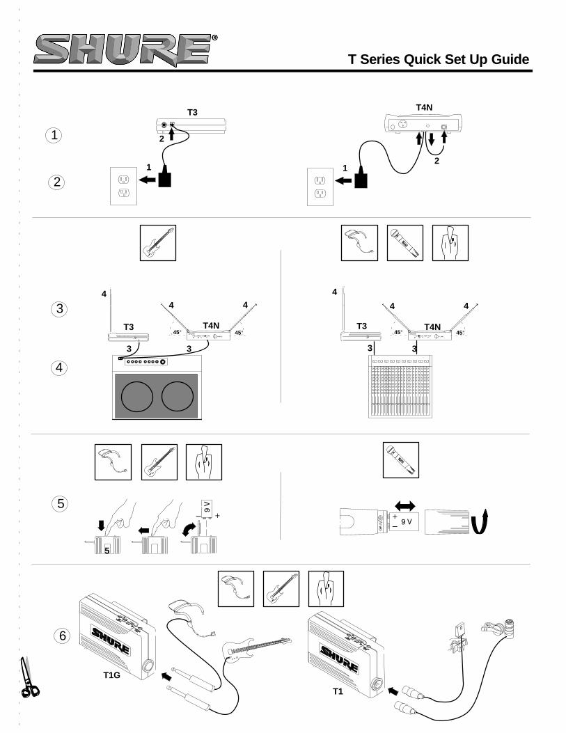
BATTERY INSTALLATION1. Slide the transmitter POWER switch to the OFF position.
2. T1, T1G, T11: Press down on the OPEN side of the batterycompartment cover, slide it back and flip it open, as shownin Figure 4.T2: Unscrew the transmitter battery cover to expose the bat-tery terminals, as shown in Figure 3.
FIGURE 4. BATTERY INSTALLATION
ÁÁÁÁ
ÁÁ
Á
ÁÁÁÁÁÁÁÁÁÁÁ
ÁÁÁÁÁ
ÁÁÁÁÁÁÁÁ
ÁÁÁÁÁ
ÁÁ
ÁÁÁÁÁÁÁÁÁÁÁÁ
ÁÁÁÁÁÁÁÁÁÁÁÁ
ÁÁÁÁÁÁ
ÁÁÁÁÁÁÁÁÁÁÁÁÁÁ
ÁÁÁÁÁÁÁÁÁÁ
ÁÁÁÁÁÁ
3. Insert a fresh 9V alkaline battery into the battery compart-ment (A Duracell MN1604 is recommended and included withthe system). A fresh 9V alkaline battery will typically provide18 hours of performance time. A fully charged 8.4V NiCadbattery will provide about 2 hours of performance time.
IMPORTANT: Carbon-zinc and zinc-chloride batteries willnot provide adequate power and are not recommended.
4. Replace the battery cover.
HEADSET ASSEMBLY1. Refer to the tag attached to the headset for assembly in-
structions. After assembling the WH20, adjust the head-band and place it on your head.
2. Position the microphone over the corner of your mouth,about 1/2 inch away. See Figure 5.
3. To reduce pops and breath noise, place the supplied foamwindscreen over the microphone.
FIGURE 5. HEADSET MICROPHONE POSITION
BODYPACK TRANSMITTER SETUP(T1, T1G, T11)
1. Attach the transmitter to your belt, guitar strap, or waistbandas shown in Figure 6. Depress the tab marked PRESS andslip the belt or strap between the transmitter body and thebelt clip. For added stability, draw the strap or belt toward theclip’s top wire, especially when using thin guitar straps.
ÁÁÁÁÁ
ÁÁÁÁÁÁÁÁÁ
ÁÁÁÁÁ
ÁÁÁÁÁÁÁÁ
ÁÁ
Á
ÁÁÁÁ ÁÁ
ÁÁÁÁ
ÁÁÁÁ
ÁÁ
T1/T1G T11
FIGURE 6. TRANSMITTER SETUP
ÁÁÁ
2. Plug your guitar, headset microphone, or lavalier micro-phone into the transmitter.
RECEIVER SETUP1. Connect the receiver to the power supply. Plug one end of the
AC power adapter into the DC INPUT connector on the backof the receiver. Plug the other end into an AC power source.The green POWER light on the receiver will glow.
T4N: Loop the power cable around the cable retainer on thebottom of the receiver. See Figure 7.
FIGURE 7. T4N POWER CABLE RETAINER
ÁÁÁÁÁÁ ÁÁÁÁÁÁÁÁÁÁÁÁÁÁÁÁÁÁÁÁÁÁÁÁÁÁÁÁÁÁÁÁÁÁÁÁÁÁÁÁÁÁÁÁÁÁÁÁÁÁÁÁÁ ÁÁÁÁÁÁÁÁÁÁÁÁÁÁÁÁÁÁÁÁÁÁÁÁÁÁÁÁÁÁÁÁÁÁÁÁÁÁÁÁÁÁÁÁÁÁÁÁÁÁÁÁÁÁÁÁÁÁÁÁÁÁÁÁÁÁ1 2
2. Connect the receiver output. The Guitarist: plug a standardguitar cable into the receiver’s output connector. Plug theother end into a guitar amplifier, as shown in Figure 8. TheHeadset, Vocalist, Presenter, or Bodypack: Use a cablewith a 1/4 inch phone plug (T3, T4N) or a female XLR con-nector (T4N). Connect the receiver to a mic level input of amixer or PA system (Figure 8).
3. Extend antenna(s). T3: The antenna should be fully ex-tended and vertical, as shown in Figure 8. T4N: The anten-nas should be fully extended and angled away from eachother, at an angle of 45 degrees from vertical, as shown inFigure 8.

English
4
WIRELESS SYSTEM OPERATION
ÁÁÁÁÁÁÁÁÁÁÁÁÁÁÁÁÁÁÁÁÁÁÁÁÁÁÁÁÁÁÁÁÁÁÁÁÁÁÁÁÁÁÁÁÁÁÁÁÁÁÁÁÁ
ÁÁÁÁÁÁÁÁÁÁÁÁÁÁÁÁÁÁÁÁÁÁÁÁ
ÁÁÁÁÁÁÁÁÁÁÁÁÁÁÁÁÁ
ÁÁÁÁÁÁÁÁÁÁÁÁÁÁÁÁÁÁÁÁ
ÁÁÁÁÁÁÁÁÁT4NT3
T1G T11
ÁÁÁÁÁÁÁÁÁÁÁÁÁÁÁÁÁÁÁÁÁÁÁÁÁÁÁÁÁÁÁÁÁÁÁÁÁÁÁÁÁÁÁÁÁÁÁÁÁÁÁÁÁÁÁÁÁÁ
SHURE
45° 45°
ÁÁÁÁÁÁÁÁÁÁÁÁÁÁÁÁÁÁÁÁÁÁÁÁÁÁ
ÁÁÁÁÁÁÁÁÁÁÁÁÁÁÁÁÁ
ÁÁÁÁÁÁÁÁÁÁÁÁÁÁÁÁÁÁÁÁ
ÁÁÁÁÁÁÁÁÁSHURE 45°45°T3 T4N
ÁÁÁÁÁÁÁÁÁÁÁÁÁÁÁÁÁÁÁÁÁÁÁÁÁÁÁÁÁÁÁÁ
ÁÁÁÁÁÁÁÁÁÁÁÁÁÁÁÁÁÁÁÁÁÁÁÁÁÁÁÁÁÁÁÁÁÁÁÁÁÁÁÁÁÁÁÁÁÁÁÁÁÁÁÁÁÁÁÁÁÁÁÁÁÁÁÁÁÁÁÁÁÁÁÁÁÁÁÁÁÁÁÁÁÁÁÁÁÁÁÁÁÁÁÁÁÁÁÁÁÁÁÁÁÁÁÁÁÁÁÁÁÁÁÁÁÁÁÁÁÁÁÁÁÁÁÁÁÁÁÁÁÁÁÁÁÁÁÁÁÁÁÁÁÁÁÁÁÁÁÁÁÁÁÁÁÁÁÁÁÁÁÁÁÁÁÁÁÁÁÁÁÁÁÁÁÁÁÁÁÁÁÁÁÁÁÁÁ
ÈÈÍ
Á SH
UR
E
ÁÁÁÁÁÁÁÁÁÁÁÁÁÁÁÁÁÁÁÁÁÁÁÁÁÁÁÁÁÁÁÁÁÁÁÁÁ
ÁÁÁÁÁÁÁÁÁÁÁÁÁÁÁÁÁÁÁÁÁÁÁÁÁÁÁÁÁÁÁÁÁÁÁÁÁÁÁÁÁÁÁÁÁÁÁÁÁÁÁÁÁÁÁÁÁÁÁÁÁÁÁÁÁÁÁÁÁÁÁÁÁÁÁÁÁÁÁÁÁÁÁÁÁÁÁÁÁÁÁÁÁÁÁÁÁÁÁÁ
ÁÁÁÁÁ
ÁÁÁÁÁÁÁÁÁÁÁÁÁÁ
ÁÁÁÁÁÁÁÁÁÁÁÁÁÁÁÁÁÁÁÁÁÁÁÁÁÁÁÁÁÁÁÁÁÁÁÁÁÁÁÁÁÁÁÁÁÁÁÁÁÁÁÁÁÁÁÁÁÁÁÁÁÁÁÁÁÁÁÁÁÁÁÁÁÁÁÁÁÁÁÁÁÁÁÁÁÁÁÁÁÁÁÁÁÁÁÁÁÁÁÁÁÁÁÁÁÁÁÁÁ
ÁÁÁÁÁ
ÁÁÁ
ÁÁÁÁÁÁÁÁÁÁÁÁÁÁÁÁ
ÁÁÁÁÁÁÁÁÁÁÁÁÁ
FIGURE 8. WIRELESS SYSTEM OPERATION
ESTABLISHING A WIRELESS LINKWhen powered on, your transmitter broadcasts an RF carriersignal. When picked up by your receiver, this signal links yourwireless system and allows wireless transfer of audio signalsfrom your microphone or instrument. The RF signal is broad-cast steadily, even when your transmitter is muted. The yellowRF light (T3) and ANTENNA A/B lights (T4N) indicate when thislink is established.To test your wireless link, setup your transmitter and receiver asdescribed in “System Setup”. Turn on your transmitter whilewatching the yellow RF or ANTENNA lights. The RF light (T3)or one of the ANTENNA lights (T4N) should illuminate.
• If the RF or ANTENNA lights do not illuminate, see theTroubleshooting section in this guide.
Turn your transmitter off. The RF or ANTENNA light should goout.
• If the RF or ANTENNA lights do not go out after you turn offyour transmitter, your receiver is picking up an RF signalfrom some other source. If you cannot identify and removethis source (usually other digital or wireless electronicequipment nearby), place your receiver in another loca-tion. If external RF sources cannot be avoided, you mayneed a wireless system that operates on a different carrierfrequency. Contact your Shure dealer.
OPERATING YOUR WIRELESS SYSTEM
1. Once you have established a wireless link, slide the trans-mitter MUTE switch to the ON position.
2. Sing, speak, or play your instrument at typical volume lev-els. (The Guitarist: turn the volume control on your guitar orbass all the way up.) Normal operation is indicated by:
• Steady glow of yellow RF light (T3) or ANTENNA light A orB (T4N).
• Flickering of the red PEAK light (T3) or TRANSMITTERAUDIO PEAK light (T4N) when loud sounds are trans-mitted.
NOTE: If the red TRANSMITTER AUDIO PEAK light on thereceiver does not flicker occasionally, refer to the WirelessSystem Adjustments Section below.
3. When finished, slide the MUTE switch to MUTE. Then slidethe transmitter POWER switch to OFF. (Muting the transmit-ter first will help prevent audio thumps that may occur whenpowering off the transmitter.)

English
5
WIRELESS SYSTEM ADJUSTMENTS
TRANSMITTER AUDIO GAIN ADJUSTMENTThe Guitarist: The audio gain control on the transmitter in TheGuitarist system is factory-preset at the minimum setting (fullcounterclockwise) to reduce the risk of overload and distortion.If the red TRANSMITTER AUDIO PEAK light on the receiverdoes not flicker when the guitar is played loudly and its volumecontrols are turned all the way up, increase the transmitter gainlevel. This will ensure the best signal-to-noise ratio for perfor-mance. See Figure 9.The Headset: The audio gain control on the transmitter in TheHeadset system is factory preset at the maximum setting (fullclockwise). This is because the microphone in the WH20 is alow output, dynamic microphone. It may be necessary to re-duce the transmitter gain until the red TRANSMITTER AUDIOPEAK light flickers only when you speak or sing loudly. This willensure the best signal to noise ratio for performance. See Fig-ure 9.The Vocal Artist, Presenter and Bodypack: The audio gain con-trols on the transmitters in The Vocal Artist, Presenter, and Body-pack systems have been factory preset at the mid-range position.This will provide the best results in most applications. However, forsingers or presenters with quiet voices, the audio gain may needto be increased for better signal-to-noise ratio. Increase the gainuntil the receiver’s TRANSMITTER AUDIO PEAK light flickerswhen you speak in a loud voice. For those with loud voices, thepreset gain level may be too high, causing unwanted distortion.In this case, the PEAK indicator will glow continuously whenyou sing or speak in a loud voice and the gain level should bereduced. See Figure 9.
FIGURE 9. GAIN ADJUSTMENT
T1/T1G
T2
T11ÁÁÁÁÁ
ÁÁÁÁÁÁÁÁÁÁÁ
ÁÁÁÁÁÁÁ
ÁÁÁÁÁÁÁÁÁÁÁÁÁÁ
ÁÁÁÁ
ÁÁÁ
ÁÁÁ
ÁÁÁ
ÁÁÁÁ
ÁÁÁÁÁ
ÁÁÁÁÁÁ
ÁÁÁÁÁÁ
ÁÁÁÁÁÁÁÁÁÁÁÁÁÁÁÁ
ÁÁÁÁÁÁÁÁÁÁÁÁÁÁÁÁÁÁÁÁÁÁÁÁ
ÁÁÁÁÁÁÁÁÁÁÁÁÁÁÁ
ÁÁÁ
ÁÁÁÁ
• To Increase Gain: Rotate the transmitter gain control clock-wise with the supplied screwdriver until the red TRANS-MITTER AUDIO PEAK light on the receiver flickers whenthe guitar is played loudly, or when you sing or speak in aloud voice.
• To Reduce Gain: Rotate the transmitter gain control counter-clockwise until the red TRANSMITTER AUDIO PEAK lighton the receiver flickers only when the guitar is playedloudly, or when you speak or sing in a loud voice.
• To Return Audio Gain to the Factory Setting: Rotate thetransmitter audio gain control counterclockwise as far as itwill go (The Guitarist), clockwise as far as it will go (TheHeadset), or to mid position (The Vocal Artist, Presenter,and Bodypack systems).
RECEIVER VOLUME ADJUSTMENTThe volume control on the front panel of the T3 and T4N receiv-ers can be adjusted to make the wireless system output levelidentical to that of a cabled guitar or bass or wired microphone.After making any necessary transmitter gain adjustments, ad-
just the receiver volume control until the output reaches the de-sired level. Rotate the volume control clockwise to increase out-put. Rotate it counterclockwise to decrease output.
RECEIVER SQUELCH ADJUSTMENTThe squelch control on the T3 and T4N receivers is factorypreset for optimum performance. No further adjustment isnormally required. It is possible to adjust the squelch controlsetting to emphasize either signal quality or system range:
• Turning the squelch control clockwise causes the receiverto demand a higher quality signal (less noise before mut-ing), but decreases operating range.
• Turning the squelch control counterclockwise allows a low-er quality signal through (more noise before muting), but in-creases operating range.
To return the receiver squelch control to the factory setting, ro-tate it to the mid-range position (so the slot is vertical).
ABOUT THE SHURE NOISE SQUELCH SYSTEMConventional squelch circuits analyze RF signal strength. Conse-quently, they cannot discriminate between noise and desired sig-nals. When a wireless system is used in a noisy RF environment,conventional circuits may “open” unexpectedly, sending loudbursts of noise through the receiver when the transmitter’s signal isweak or turned off. Unlike conventional wireless systems, ShureT-Series systems use a noise squelch circuit that analyzes signalquality instead of signal strength. A special detector monitors thelevel of high frequency noise. When the transmitter signal isstrong, the system’s noise level is low and the receiver sends au-dio through. When the transmitter signal is weak or absent, thesystem’s noise level is high and the squelch circuit will mute thereceiver. This virtually eliminates the possibility of annoying burstsof noise coming through your receiver.
TIPS FOR ACHIEVING MAXIMUM PERFORMANCE• Make sure you can always see a receiver antenna from the
transmitter position.• Keep the distance between the transmitter and the receiv-
er antennas short.• Avoid placing the receiver antennas near metal surfaces
and obstructions. They will reduce system performance.• To mount the receiver on a flat surface, attach the four
adhesive rubber feet or secure the receiver to the surfacewith the supplied cloth fastening strips.

English
6
TROUBLESHOOTING
PROBLEM
INDICATOR STATUS
TRANS-MITTER
T3 RECEIVER
T4N RECEIVER
= on = flickers on loud peaksSOLUTIONS
POWER ANTENNA AUDIO
PEAKPOWER RF
PEAKA BON
POWER
LOW BATT
TRANSMITTER• Slide transmitter POWER switch to ON.• Make sure battery is inserted properly (+/– battery terminals must
match transmitter terminals).• Insert fresh battery.
POWER ANTENNA AUDIO
PEAKPOWER RF
PEAKA BON
POWER
LOW BATT
TRANSMITTER• Make sure AC adapter is securely plugged into electrical outlet
and into DC input connector on rear panel of receiver.• Make sure AC electrical outlet works and supplies proper volt-
age.
No sound. POWER ANTENNA AUDIO
PEAKPOWER RF
PEAKA BON
POWER
LOW BATT
TRANSMITTER
• Slide transmitter MUTE switch to ON.
POWER ANTENNA AUDIO
PEAKPOWER RF
PEAKA BON
POWER
LOW BATT
TRANSMITTER • Extend antenna(s). T4N receiver antennas should point awayfrom each other at a 45° angle from vertical; T3 receiver antennashould remain vertical. See Figure 8.
• Move receiver away from nearby metal objects.• Remove obstructions and maintain line of sight between transmit-
ter and receiver.• Move transmitter closer to receiver.
No sound or faint
POWER ANTENNA AUDIO
PEAKPOWER RF
PEAKA BON
POWER
LOW BATT
TRANSMITTER
• Increase transmitter gain until Transmitter Audio Peak light flasheson loud peaks.
• Turn up receiver volume control as necessary.No sound or faintsound.
POWER ANTENNA AUDIO
PEAKPOWER RF
PEAKA BON
POWER
LOW BATT
TRANSMITTER
• Turn up receiver volume control.• Check cable connection between receiver and amplifier or mixer.
Sound level from thereceiver is differentfrom that of a cabledguitar or microphone.
• Adjust transmitter gain as necessary.• Adjust receiver volume as necessary.
Sound level is differentwhen you changeguitars.
• Adjust transmitter gain to compensate for differences between gui-tar output levels.
Distortion increasesgradually.
POWER
LOW BATT
• Replace transmitter battery.
Bursts of noise,distortion, or other radiosignals interruptperformance.
ANTENNA
RF
A B
POWER
LOW BATT
• If noise occurs when transmitter is turned off, remove or turn offnearby sources of RF (such as other wireless systems, CB radios,etc.).
• Use a wireless system that operates on a different frequency.
Momentary loss ofsound as transmitter ismoved aroundperforming area(dropouts).
ANTENNA
RF
A B
POWER
LOW BATT
• Reposition receiver and perform walk-through test. If audio drop-outs persist, mark “dead” spots and avoid them during perfor-mance.
English
7
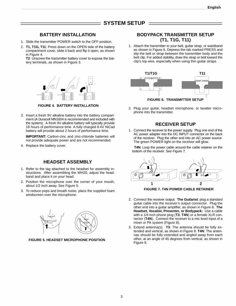
SYSTEM AND COMPONENT SPECIFICATIONS
RF Carrier Frequency Range169.445 to 240.000 MHz (Available frequencies depend on
applicable regulations in country where system is used).Operating Range:100 m (328 ft.) under typical conditionsAudio Frequency Response: 50 to 15,000 Hz, 3 dBImage Rejection: 60 dB typicalSpurious Rejection: > 60 dB typicalSystem Distortion (ref. 15 kHz deviation, 1 kHz modula-tion): 0.1% THD typicalSignal/Noise Ratio: 101 dBSensitivity: –109 dBm for 12 dB SINAD typicalOperating Temperature Range:
–18° to 57° C (0° to 135° F) NOTE: Battery characteristicsmay limit this range.
Battery Life: 18 hours with 9 V alkaline battery (DuracellMN1604 recommended).
T1, T1G AND T11 BODYPACK TRANSMITTERSPECIFICATIONS
RF Output 50 mW typical (T1, T1G); 20 mW typical (T11)
InputConfiguration
Unbalanced
Connector Type 1/4 Inch (T1G); 4-pin Miniature Connector (male)(T1)
ActualImpedance
1 MΩ
MaximumRecommendedInput Level*
+3 dBV
MinimumRecommendedInput Level**
–80 dBV
Connector PinAssignments(T1, T11)
Pin 1:Tied to GroundPin 2:Tied to +5 VPin 3:Tied to AudioPin 4:Tied to 20kΩ Resistor and Audio Ground
Connector PinAssignments(T1G)
Sleeve: Tied to GroundTip: Tied to Audio
Dimensions (T1, T1G)
64 mm H x 106 mm W x 24 mm D (2.52” H x 4.17” W x 0.95” D)
Dimensions (T11) 83 mm H x 64 mm W x 26 mm D (3.27” H x 2.50” W x 1.03” D)
Net Weight(T1,T1G)
96.4g (3.4 oz.)
Net Weight (T11) 79.4g (2.8 oz.)
PowerRequirements
9 V alkaline battery (Duracell MN1604recommended); 8.4 V NiCd battery optional.
Nominal CurrentDrain
30 mA
* Gain Control at minimum** Gain Control at maximum
T2 HAND-HELD TRANSMITTER SPECIFICATIONS
T2/58(SM58 ) T2/(PG58 )
RF Output 50 mW Typical (FCC); 20 mW Typical (ETSI)
Dimensions 236 mm H x 51 mm D (9.29” H x 2.01” D)
222 mm H x 51 mm D (8.74” H x 2.01” D)
Net Weight 295 g (10.4 oz.) 266 g (9.4 oz.)
Power Requirement 9 V alkaline battery (Duracell MN1604 recom-mended); 8.4 V NiCd battery optional.
Nominal CurrentDrain
30 mA 30 mA
T3 AND T4N RECEIVER SPECIFICATIONS
T4N T3
Connector 3-Pin XLR (Male) and1/4” Phone Jack
1/4” Phone Jack
Maximum OutputLevels
1/4”: +5 dBVXLR: –10 dBV
–6.8 dBV
Nominal OutputLevels
1/4”: –8 dBVXLR: –30 dBV
–32 dBV
OutputConfiguration
Active Balanced Unbalanced
Actual Impedance 3.3 KΩ 1 KΩConnector PinAssignments
XLR: Pin 1: ground;Pin 2: hot; Pin 3: cold1/4”: Tip: hot; Sleeve:ground.
Tip: hot; Sleeve:ground
Dimensions (T4N) 41 mm H x 197 mm W x 138 mm D(1.625” H x 7.77” W x 5.42” D)
Dimensions (T3) 35mm H x 152 mm W x 98 mm D(1.38”H x 5.98” W x 3.85” D)
Net Weight (T4N) 435 g (15.4 oz.)
Net Weight (T3) 192 g (6.8 oz.)
PowerRequirements
12–18 VDC nominal, 200mA
Power Supply 120 V or 230V AC adaptor with 2.1 mm femaleplug
Voltage/Current/Phantom PowerProtection
Yes Yes
Certification
T1G, T1:Accepted under FCC Parts 74 and 90. Certified by ICin Canada under TRC-78.
T11: Conforms to European Union directives, eligible to bear CEmarking; meets European Union Requirements. Type Ap-proval: pr I–ETS 300 422, BZT 17 TR 2019, and BAPT 122R 1. Meets Requirements of EMC Standard 301-489-1and –9
T2/PG58, T2/58: Type Accepted under FCC Parts 74 and 90.Certified by IC in Canada under TRC-78. Conforms toEuropean Union directives, eligible to bear CE marking;meets European Union Requirements. Type Approval: prI–ETS 300 422, BZT 17 TR 2019, and BAPT 122 R 1. MeetsRequirements of EMC Standard 301-489-1 and –9
T3: Approved under the Notification provision of FCC Part 15.Certified by IC in Canada under TRC–78.
T4N: Approved under the Declaration of Conformity (DoC)provision of FCC part 15. Certified by IC in Canada underRSS-210. Conforms to European Union directives, eleg-ible to bear the CE marking. Meets Requirements of EMCStandard 301-489-1 and –9
T11 and T2 Transmitters meet the essential requirements ofthe European R&TTE Directive 99/5/EC and are eligible tocarry the CE marking. O682
T3 and T4 Receivers meet the essential requirements of theEuropean R&TTE Directive 99/5/EC and are eligible tocarry the CE marking.
Power supply meets the following safety standard:
PS20 Power Supply: UL 1310, CAN/CSA 22.2 No. 223.
PS20E Power Supply: EN 60065/09.93.
PS20UK Power Supply: EN 60065 5th, 1985.

English
8
THIS RADIO EQUIPMENT IS INTENDED FOR USE IN MUSICAL PROFESSIONAL ENTERTAINMENT AND SIMILAR APPLICATIONS.
NOTE: THIS RADIO APPARATUS MAY BE CAPABLE OF OPERATING ON SOME FREQUENCIES NOT AUTHORIZED IN YOUR REGION. PLEASECONTACT YOUR NATIONAL AUTHORITY TO OBTAIN INFORMATION ON AUTHORIZED FREQUENCIES FOR WIRELESS MICROPHONE PRODUCTSIN YOUR REGION
Frequency Range of Apparatus: 169 MHz–250 MHzLicensing: A ministerial license to operate this equipment may be required in certain areas. Consult your national authority for possiblerequirements.
Shure Transmitters Models T11 and T2 may be used in the countries and frequency ranges listed in Table 1.
ACCESSORIES, LICENSING AND WARRANTY
FURNISHED ACCESSORIESGain Adjustment Screwdriver 65A1659. . . . . . . . . . . . . . . . . Sew–in Mounting Block
(WL93; Presenter Systems Only) 65B1733*. . . . . . . . . . Receiver AC Adapter
PS20 (120V), PS20E (220V), PS20UK. . . . . . . . . . . . . . Guitar Cables (Guitarist systems only)
1/4” to 1/4” WA303. . . . . . . . . . . . . . . . . . . . . . . . . . . . . . . . 1/4” to Mini Connector WA302. . . . . . . . . . . . . . . . . . . . . .
Swivel Adapter (Vocal Artist Systems Only) WA371. . . . . . Plastic Carrying Case (Diversity Systems) WA605. . . . . . . Plastic Carrying Case (Non-diversity Systems) WA600. . . .
∗ Replacements furnished in multiples of 4.
OPTIONAL ACCESSORIES AND REPLACEMENTPARTS
Anti–Roll Device for Handheld Transmitters A1K. . . . . . . . . Neoprene Bodypack Belt Pouch WA570. . . . . . . . . . . . . . . . Line Matching Output Transformer (T3 Receiver) A95U. . . . 1.8 Meter (6 ft.) Receiver-Mixer Cable WA410. . . . . . . . . . . Rack-Mount Kit (T4N Diversity Systems Only) URT. . . . . . . Amp/Powered Mixer stand for Receivers WA595. . . . . . . . .
Presenter Systems OnlyTan version of WL93 WL93T. . . . . . . . . . . . . . . . . . . . . . . . . . Single-Mount Tie Clip (2)
(WL93) RK354SB. . . . . . . . . . . . . . . . . . . . . . . . . . . . . . . . . Dual-Mount Tie Clip
(WL93) RK307DB. . . . . . . . . . . . . . . . . . . . . . . . . . . . . . . . . Black Windscreen (4)
(WL93) RK355WS. . . . . . . . . . . . . . . . . . . . . . . . . . . . . . . . . Tan Windscreen and Tie Clip (2 each)
(WL93) RK304T. . . . . . . . . . . . . . . . . . . . . . . . . . . . . . . . . . . Replacement Cartridges (compatible
with WL184, WL185) R183B, R184B, R185B. . . . . . . . . . Tie Clip Single Microphone Holder (2)
(WL184, WL185) RK183T1. . . . . . . . . . . . . . . . . . . . . . . . Tie Clip Dual Microphone Holder (1)
(WL184, WL185) RK183T2. . . . . . . . . . . . . . . . . . . . . . . . Black Snap–fit Windscreens (4)
(WL184, WL185) RK183WS. . . . . . . . . . . . . . . . . . . . . . . . Black Foam Windscreen (4)
(WL 184, WL185) RK261BWS. . . . . . . . . . . . . . . . . . . . . .
Headset Systems Only
Foam Windscreens (2) and Clothing Clip (WH20)RK318WSCroakies Headband (WH20) RK319. . . . . . . . . . . . . . . . . . . Croakies Headband and Wire Frame (WH20) RPM600. . Microphone and Boom Assembly (WH20)
1/4” plug RPM100. . . . . . . . . . . . . . . . . . . . . . . . . . . . . . . . Miniature Connector plug RPM102. . . . . . . . . . . . . . . . . .
For additional microphone service or parts information, pleasecontact Shure’s Service department at 1–800–516–2525 orShure’s website at www.shure.com. Outside the United States,please contact your Authorized Shure Service Center.
WARRANTY INFORMATIONShure Incorporated (“Shure”) hereby warrants that these prod-ucts will be free from defects in material and workmanship for aperiod of two years from the date of purchase for all microphonecartridge and housing assembly parts and, for a period of oneyear from the date of purchase, all transmitter and receiverparts. At its option, Shure will repair or replace the defectiveproduct and promptly return it to you. You should retain proof ofpurchase to validate the purchase date and return it with anywarranty claim. If you believe this product is defective within thewarranty period, carefully repack the unit, insure it, and return itpostpaid to:
Shure IncorporatedAttention: Service Department222 Hartrey AvenueEvanston, IL 60202-5730 U.S.A.
Customers outside the U.S.A. should ship the product to the au-thorized Shure Distribution Center in their region.
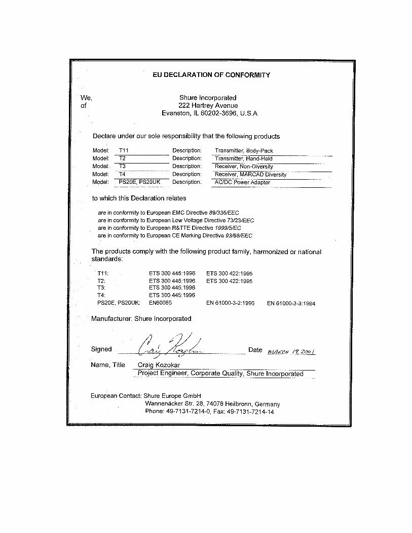
DECLARATION OF CONFORMITYWe of
Shure Incorporated222 Hartrey Ave.Evanston IL 60202–3696 U.S.A.847–866–2200
declare under our sole responsibility that the following products,Model: T3 Name: T3 ReceiverModel: T4N Name: T4N Diversity Receiver
were tested and found to comply with Part 15 of the FCC rules.Operation is subject to the following two conditions: (1) this device may notcause harmful interference, and (2) this device must accept any interferencereceived, including interference that may cause undesired operation.Testing was completed by the following NVLAP or A2LA accredited labora-tory:
BZT privat CETECOM GmbH66117 SarbrukenUnterturkheimer StrBe 6–10Deutschland telephone +49 681 598 – 9000fax +49 681 598 – 9075
Shure Inc., Manufacturer.
Signed: Date: June 15, 1999
Name, Title: Craig Kozokar, Senior Quality EngineerADDITIONAL INFORMATION FOR THIS SHURE WIRELESS SYSTEMThis Shure wireless transmitter is accepted under FCC Part 74 and/or Part 90.IMPORTANT: Licensing of Shure wireless microphone equipment isthe user’s responsibility, and licensability depends on the user’s clas-sification and application, and on the selected frequency. Shure urgesthe user to consult the appropriate telecommunications authority beforechoosing and ordering frequencies.
Changes or modifications not expressly approved by Shure Inc. couldvoid your authority to operate this equipment.

65
TABLE 1 TABLEAU 1 TABELLE 1 TABLA 1 TABELLA 1
Country CodeCode de PaysLander–KurzelCodigo de Pais
Codice del Paese
T11, T2(169 – 250 MHZ)
A 230 – 250 MHZ *
B 174 – 223 MHZ *
CH 174 – 223 MHZ *
D 174 – 223 MHZ *
E 174 – 223 MHZ *
F 174 – 223 MHZ *
GB 174 – 223 MHZ *
GR *
I 174 – 223 MHZ *
IRL *
L *
NL 174 – 223 MHZ *
P 174 – 223 MHZ *
DK *
FIN 174 – 223 MHZ *
N 174 – 223 MHZ *
S 174 – 223 MHZ *
All Other CountriesTous les autres paysAlle anderen Länder
Demás paísesTutti gli altri Paesi
*
*Please contact your national authority for information on available legal frequencies for your area and legal use of the equipment.
*Se mettre en rapport avec les autorités compétentes pour obtenir les informations sur les fréquences autorisées disponibles localement etsur l’utilisation autorisée du matériel.
*Für Informationen bezüglich der für Ihr Gebiet verfügbaren gesetzlich zugelassenen Frequenzen und der gesetzlichen Bestimmungenfür den Einsatz der Geräte setzen Sie sich bitte mit der zuständigen örtlichen Behörde in Verbindung.
* Comuníquese con la autoridad nacional para obtener información en cuanto a las frecuencias legales disponibles y usos legales delequipo en su área.
*Rivolgersi alle autorità competenti per ottenere informazioni relative alle frequenze autorizzate nella propria regione e alle norme cheregolano l’uso di questo apparecchio.

SHURE Incorporated Web Address: http://www.shure.com222 Hartrey Avenue, Evanston, IL 60202–3696, U.S.A.Phone: 847-866–2200 Fax: 847-866-2279In Europe, Phone: 49-7131-72140 Fax: 49-7131-721414In Asia, Phone: 852-2893-4290 Fax: 852-2893-4055Elsewhere, Phone: 847-866–2200 Fax: 847-866-2585