
SHREVEPORT/BOSSIER CITY ITS DEPLOYMENT IMMEDIATE · to be deployed. This process will give the...
97
SHREVEPORT/BOSSIER CITY ITS DEPLOYMENT IMMEDIATE TERM PHASE 2 Systems Engineering Analysis July 2006 Presented to: The Louisiana Department of Transportation And Development And The Federal Highway Administration FOR INFORMATIONAL PURPOSES ONLY
Transcript of SHREVEPORT/BOSSIER CITY ITS DEPLOYMENT IMMEDIATE · to be deployed. This process will give the...
SHREVEPORT/BOSSIER CITY
ITS DEPLOYMENT IMMEDIATE
TERM PHASE 2
Systems Engineering Analysis
July 2006
Presented to: The
Louisiana Department of Transportation And Development
And The Federal Highway Administration
FOR INFORMATIO
NAL PURPOSES O
NLY

July 2006 1
Chapter 1.0 Introduction.............................................................................................. 3 1.1 Purpose................................................................................................................ 3 1.2 Systems Engineering Approach.......................................................................... 3
Chapter 2.0 Existing Conditions and Needs Analysis ...................................................... 5 2.1 Project Limits..................................................................................................... 5 2.2 Description of the Travel Corridor ..................................................................... 6 2.3 Local Environment.............................................................................................. 7 2.4 Existing ITS Elements and Infrastructure........................................................... 7 2.5 Needs Analysis.................................................................................................... 9
Chapter 3.0 Implementation of Project Architecture...................................................... 10 3.1 National ITS Architecture................................................................................. 10
3.1.1 User Services ............................................................................................ 11 3.1.2 Logical Architecture ................................................................................. 12 3.1.3 Physical Architecture ................................................................................ 13 3.1.4 Implementation of Strategy....................................................................... 14 3.1.5 Standards Requirements............................................................................ 14
3.2 Review of Shreveport/Bossier City Regional ITS Strategic Deployment Plan 14 3.2.1 User Services and Market Packages .............................................................. 16 3.2.2 Subsystems and Equipment Packages ...................................................... 16 3.2.3 Shreveport/Bossier City Regional ITS Physical Architecture .................. 19 3.2.4 Recommended Standards for Shreveport/Bossier City Region ................ 21
3.3 Shreveport/Bossier City ITS Deployment Immediate Term Phase 2 Project... 23 3.3.1 User Services ............................................................................................ 24 3.3.2 Project Logical Architecture ..................................................................... 24 3.3.3 Project Physical Architecture.................................................................... 25 3.3.4 Project Market Packages........................................................................... 26 3.3.5 Relevant Project ITS Standards ................................................................ 27 3.3.6 Integrating Project Architectures with Existing Regional Architectures.. 29
Chapter 4.0 Concept of Operations................................................................................. 29 4.1 Purpose............................................................................................................. 29 4.2 Stakeholders...................................................................................................... 30 4.3 Functions and Processes ................................................................................... 30
Chapter 5.0 System Requirements Definitions.......................................................... 38 5.1 Functions the System Will Perform.................................................................. 38 5.2 Identify System Components............................................................................ 39 5.3 System Interfaces .............................................................................................. 39 5.4 Project Architecture ............................................................................................. 40
5.4.1 Subsystems................................................................................................ 50 5.5 Stakeholder Requirements ................................................................................ 53
5.5.1 Motorist Advisory Elements .......................................................................... 53 5.5.2 Traffic Signal Control ...................................................................................... 53 5.5.3 Traffic Flow Verification.......................................................................... 54 5.5.4 Video Surveillance.................................................................................... 54 5.5.5 LADOTD District 04 TMC Central System............................................. 55 5.5.6 LADOTD Maintenance Management System.......................................... 55 5.5.7 Data Archival Systems.............................................................................. 55
FOR INFORMATIO
NAL PURPOSES O
NLY
July 2006 2
5.5.8 Caddo Communications District / SPD Dispatch / CSO Dispatch / LSP Dispatch 56
5.6 Project Functional Requirements...................................................................... 56 Chapter 6.0 Alternative System Configurations Analysis ............................................. 58
6.1 Component Technologies ................................................................................. 58 6.1.1 Traffic Signal Control ............................................................................... 58 6.1.2 Traffic Flow Measurement ............................................................................ 59 6.1.3 Video Surveillance.................................................................................... 60 6.1.4 Traffic Management Systems ................................................................... 60 6.1.5 Archived Data Management Systems............................................................ 61
6.2 Communications Technologies............................................................................... 61 6.2.1 Center-to-Field Interfaces .............................................................................. 61 6.2.2 Center-to-Center Interfaces............................................................................ 62 6.2.3 Field Responder to Center Interfaces............................................................. 62 6.2.4 Field Responder to Field Responder.............................................................. 63 6.3 Summary ............................................................................................................. 63
Chapter 7.0 Procurement Options................................................................................... 64 7.1 Procurement Options of ITS Technologies...................................................... 64
7.1.1 Non-Exempt Commodities ....................................................................... 64 7.1.2 Exempt Commodities................................................................................ 65
7.2 ITS Hardware Technologies ............................................................................. 65 7.3 Software ............................................................................................................ 66 7.4 Communications .............................................................................................. 66 7.5 Project Procurement Methods Available for Use by LADOTD....................... 67
7.5.1 Sealed Bid ................................................................................................. 68 7.5.2 Design-Build ............................................................................................. 69 7.5.3 Request for Quotations ............................................................................ 69 7.5.4 Leasing..................................................................................................... 70
7.6 Procurement Method for Project...................................................................... 70 Chapter 8.0 Standards ..................................................................................................... 71
8.1 Project Standards .............................................................................................. 71 8.1.1 Center-to-Field Standards ......................................................................... 72
8.2 Standards Applicable to the Project................................................................. 73 8.3 Testing.............................................................................................................. 76
8.3.1 Unit Testing .............................................................................................. 76 8.3.2 Integration Testing .................................................................................... 76 8.3.3 System Testing.......................................................................................... 77
Chapter 9.0 Documenting Resources and Procedures to Manage the System ............... 77 9.1 Operational Procedures.................................................................................... 78
9.1.1 Traffic Incident Management System (TIMS) ......................................... 78 9.1.2 Alternative Route Plan (ARP) .................................................................. 79
9.2 Maintenance Procedures ................................................................................... 80 9.3 Staff Requirements............................................................................................ 80
9.3.1 Staffing Costs............................................................................................ 81 9.4 Life-Cycle Funding........................................................................................... 81
FOR INFORMATIO
NAL PURPOSES O
NLY

July 2006 3
Chapter 1.0 Introduction To assure interoperability of physical systems and a coherent traffic management program, the implementation of Intelligent Transportation System (ITS) projects requires consideration as to how the project will fit into the national and regional ITS Architectures. The Federal Highway Administration (FHWA) has developed and mandated that a “Systems Engineering” process be used whenever ITS technologies are to be deployed. This process will give the implementing agency confidence that resources are being used optimally, returning the maximum value for transportation dollars spent. 1.1 Purpose The Louisiana Department of Transportation and Development (LADOTD) is developing the Shreveport/Bossier City ITS Deployment Immediate Term Phase 2 project for LA 526 (Bert Kouns Industrial Loop Expressway) between I-20 and LA 3132 (Inner Loop Expressway). The purpose of the project is to improve traffic operations and safety along this major arterial through the deployment of information technologies that will help coordinate the operation of traffic signal systems, improve emergency response to traffic incidents, collect data to measure performance and assist other business processes addressed in the system analysis. Project benefits for motorists include improved travel times and facilitate operational reliability. The LADOTD District 04 is working closely with the City of Shreveport and other local transportation and emergency response agencies in the implementation and subsequent operation of this project. A critical component of this project is the evaluation, design and implementation of various ITS technologies. ITS technologies will be used for traffic monitoring, traffic signal operations, incident evaluation and management, and motorist communications. These technologies may include fiber optic cable, wireless communications, traffic signal upgrades, dynamic message signs, video cameras, and vehicle traffic flow detection. In compliance with the federal mandate, LADOTD is conducting this systems engineering analysis for the Shreveport/Bossier City ITS Deployment Immediate Term Phase 2 project. The analysis will focus on identifying and addressing user (Customer/Stakeholders) needs that are consistent with the National ITS architecture and the Shreveport / Bossier City Regional ITS Strategic Development Plan dated May 2002. 1.2 Systems Engineering Approach The Systems Engineering approach offers a structured way of thinking to achieve project goals and objectives. This approach combines skills associated with engineering, project management and soft sciences (economic, social and legal). This approach helps to address all issues and provide completeness to the system. Systems Engineering also provides for “traceability”, important when considering future changes to the system design and operation. Traceability is the ability to track every requirement in the system to the system component that satisfies it. Figure 1-1, the “V” Diagram or Model, is a
FOR INFORMATIO
NAL PURPOSES O
NLY

July 2006 4
visual illustration of the Systems Engineering process used for ITS, with each step involved as the project progresses through development.
Figure 1-1: “V” Diagram Illustrating Systems Engineering Process
The left side of the “V” Diagram provides a ‘top-down’ approach for system planning and design development while the right side provides ‘bottom-up’ implementation approach for systems testing and verification. The left side of the “V” must take into account the corresponding processes across on the right side of the “V”. The “V” diagram is a composition of three different perspectives, namely user’s perspective, engineer’s perspective and contractor’s perspective. The Customer/Stakeholder’s (user’s) perspective helps to present the list of requirements. The engineer’s perspective deals with detailed subsystem components design to achieve stated requirements. The contractor’s perspective deals with the actual deployment of the system components ensuring compliance with the design specifications.
FOR INFORMATIO
NAL PURPOSES O
NLY

July 2006 5
Chapter 2.0 Existing Conditions and Needs Analysis This chapter describes the exiting conditions and needs of the study area. The objective of this chapter is to provide a general understanding of the physical characteristics of the study area and the operational responsibilities of LADOTD District 04, City of Shreveport Traffic Engineering Department, and local emergency response agencies. Also, this chapter will identify the need to improve traffic operations management in the study area. 2.1 Project Limits The greater portion of the project consists of LA 526 from I-20 located in the southwestern quadrant of Shreveport extending east/southeast intersecting I-49 and terminating at LA 3132, a distance of approximately 13 miles. Another roadway component of the study area is I-49 between the interchanges of I-49/LA 526 and I-49/LA 3132, a distance of approximately 1.5 miles. The final contiguous roadway component is LA 3132 between I-49 East to LA 526, a distance of approximately 1.5 miles. There are five additional locations included in the study area that are not necessarily contiguous to the LA 526 and I-49 portions of the project. These locations include the intersections of LA 1/LA 511 and LA 1/LA 526 and the three existing dynamic message signs located near the following interchanges: I-20/LA 526, I-20/I-220, and I-49/LA 526. Figure 2-1 shows project limits.
Figure 2-1: Project Limits
FOR INFORMATIO
NAL PURPOSES O
NLY

July 2006 6
2.2 Description of the Travel Corridor The principle roadway in the study area is LA 526. This segment of roadway is a major east/west mostly undivided arterial (divided at Linwood Ave. and Ellerbe Rd.) with left turn lanes at the major intersections. The facility has four twelve-foot travel lanes. The route has a combination of outside shoulders and curb and gutters throughout the project limits. Average daily traffic for this segment ranges for 15,000 to 32,000 vehicles. There are sixteen (16) signalized intersections with in the segment. These signals are a combination of actuated and fixed time, with some having communications links. The signal locations are as follows.
• LA 526 at West 70th St.; • LA 526 at Julie Frances Dr & Floumoy Lucas Rd.; • LA 526 at General Motors Blvd.; • LA 526 at Woolworth Rd.; • LA 526 at Buncombe Rd.; • LA 526 at Flournoy Lucas Rd.; • LA 526 at Dean Rd.; • LA 526 at Walker Rd.; • LA 526 at Mansfield Rd.; • LA 526 at Baird Rd.; • LA 526 at Blom Blvd.; • LA 526 at Kingston Rd.; • LA 526 at Linwood Ave.; • LA 526 at I-49; • LA 526 at Metroplex Dr.; and • LA 526 at St.Vincent Ave.
LA 526 is a major arterial with intersecting major and minor streets. Access control includes traffic signals and stop signs as required by State traffic operational standards. Additionally, uncontrolled access points such as curb cuts for businesses and residential, are also regulated by State standards and permitting. LA 526 has three railroad crossings within the study area. An at-grade railroad crossing (Union Pacific RR) is located just east of Mansfield Rd. and the elevated railroad crossings are located approximately 1350 feet south of Flournoy Lucas Road (Union Pacific RR) and approximately 100 feet west of LA 523 (Ellerbe Rd.) (Kansas City Southern RR). The at-grade crossing has been identified in the Shreveport/Bossier City Regional ITS Strategic Deployment Plan, 2002 as a rail crossing safety concern. I-49 is a north/south limited access facility, with six twelve-foot travel lanes. The facility has inside and outside shoulders. Average daily traffic within the study area is approximately 31,400 vehicles.
FOR INFORMATIO
NAL PURPOSES O
NLY

July 2006 7
LA 3132 is an east/west divided major arterial facility with four travel lanes and outside shoulder. Average daily traffic within the study is approximately 31,000. LA 3132 is currently being extended south across LA 526 and will connect with LA 523, Flournoy Lucas Rd. The completion of this project will transform the LA 526 / LA 3132 intersection into a major interchange. 2.3 Local Environment The roadway facilities and isolated intersections within the study boundaries are located in the southwest quadrant of the Shreveport metropolitan area. Maintenance of the roadways within the study area is the responsibility of LADOTD District 04 (with City of Shreveport under contract to District 04 for mowing and litter services). Their headquarters is located in Bossier City. LADOTD and the City of Shreveport have implemented a Signal Maintenance Agreement. By this agreement, traffic engineering, timing operations, and maintenance of the traffic signals located within the project limits are predominately the responsibility of the City of Shreveport Traffic Engineering Department. LADOTD District 04 is responsible for timing operations and maintenance of LA 526 at General Motors Blvd and LA 526 at Julie Francis Road. The project is located primarily within the city limits of Shreveport. However there is a small segment of LA 526 that is solely under the jurisdiction of Caddo Parish. Public safety services (i.e. police) for the study area are provided by the City of Shreveport police department and the Caddo Parish Sheriff’s Office. The roadways within the project boundaries have been identified in the Shreveport/Bossier City Regional ITS Strategic Deployment Plan, 2002 as being heavily congested and/or potentially will be heavily congested. The areas within the project limits that have been identified as congested are LA 526 from Flournoy Lucas Rd. to Baird Rd. and from Linwood Ave. to LA 3132. The areas within the project limits that have been identified for probable future congestion include LA 526 from Walker Rd. to I-20, and I-49 from I-20 to LA 526. 2.4 Existing ITS Elements and Infrastructure Currently the 16 traffic signals located at various intersections within the project limits can be considered “deployed ITS field devices”. Individual traffic signals operate either on a fixed-time basis or are actuated by traffic conditions. The communications plant that may be available to interconnect ITS field devices is currently limited within the study area. LADOTD shares four strands of fiber optic cable located along I-49 with Sun America, a private telecommunications company. This fiber plant extends from I-20 south to Alexandria and Lafayette. Figure 2-3 shows existing LADOTD communication infrastructure within the study area.
FOR INFORMATIO
NAL PURPOSES O
NLY

July 2006 8
FOR INFORMATIO
NAL PURPOSES O
NLY

July 2006 9
Other communication plants that should be mentioned are that of the Shreveport/Bossier City ITS Deployment Immediate Term Phase 1 (S.P. No. 737-04-0055) “Golden Triangle”, the Shreveport/Bossier City ITS Near Term Phase 1 (S.P. No. 737-94-0028) and Phase 3A (S.P. No. 737-94-0030) projects. Immediate Term Phase 1 has been completed. Near Term Phase 1 is currently being constructed and includes a 48 count single mode fiber backbone extending approximately 10 miles along I-20 from the I-20/I220 interchange east to the I-20/Industrial Ave. interchange. Design of Phase 3A is complete but has not yet been contracted. As part of the Phase 3A project, the 48 count fiber backbone installed in Phase 1 will be extended west to the I-20/LA 526 interchange. 2.5 Needs Analysis The need for the ITS applications within the project limits was identified in the Shreveport/Bossier City Regional ITS Strategic Deployment Plan. From a series of local stakeholder interviews, 17 primary transportation issues were identified for the Shreveport/Bossier City metropolitan area. They are:
• Interstate Congestion / Capacity Deficiencies; • Arterial Capacity Deficiencies; • Outdated / Antiquated Surface Street Control System; • Delay and Safety at Highway / Rail Grade Crossings; • Bridge Capacity and System Linkage; • Lack of Real-Time Traveler Information; • Effects of Incidents /Non-Recurring Congestion / Incident Management; • Ability to Quickly Detect, Locate and Verify Incidents, Incident Management
Training; • Inter-Agency Coordination and Operation of Surface Street Control System; • Construction Zone Safety and Congestion; • Communications Among Emergency Management Agencies; • Security on Transit Buses; • Lack of Real-Time Information / Status to Transit Users; • Centralized Control and Management of Transportation System; • Lack of Funding for Capacity Improvements and Maintenance; • Fleet management /AVL; and • Bicyclist and Pedestrians
Of these, there are four primary and six secondary issues that can be directly associated with this project and addressed with various ITS applications. The four primary issues include: an outdated/antiquated traffic signal system, arterial capacity deficiencies (exacerbated by a deficient traffic signal system), traffic delays and vehicle safety at highway/rail grade crossing, and interstate congestion. The six secondary issues include: real-time traveler information, effects of non-recurring congestion and incident management, detection and verification of incidents, interagency operation of street control systems, emergency management coordination, and centralized management of the transportation system.
FOR INFORMATIO
NAL PURPOSES O
NLY
July 2006 10
Additionally, it is LADOTD’s objective to use ITS technologies to actively manage traffic incidents by providing alternative routing and motorist information during major freeway traffic incidents. LA 526 may be used as a diversion route for traffic incidents occurring on I-20 and I-49. Chapter 3.0 Implementation of Project Architecture The development and deployment of ITS strategies and technologies is influenced by three levels of interconnected architectures: national, state, and regional. A goal for deploying local ITS projects is that they be planned and designed consistently with these architectures. By doing so assures the interoperability of project ITS technology with other regional and statewide ITS deployments, and maximizes operational and maintenance efficiency. The ITS project architecture for the Shreveport/Bossier City ITS Deployment Intermediate Term Phase 2 project must be consistent with the National ITS architecture as well as the Shreveport/Bossier City Regional ITS Strategic Development Plan, which is focused within the metropolitan area. This chapter is organized to assist the reader in recognizing the relationship of the project architecture with that of the National ITS architecture and the Shreveport/Bossier City Regional ITS architectures. This chapter presents:
1. An overview of the National ITS architecture; 2. Summary of the Shreveport/Bossier city regional ITS architecture; and 3. A description of the Shreveport ITS Intermediate Phase 2 project elements and
architecture. The description of the Shreveport/Bossier City ITS Deployment Immediate Term Phase 2 project architecture is presented in this chapter for comparative purposes with the relevant national and regional architectures. However, it should be noted at this time that Chapters 4 through 9 of this document will develop and present in detail the system engineering components, architecture, and processes of the project as required for federally funded ITS projects. 3.1 National ITS Architecture The National ITS Architecture describes the collection, processing, and distribution of information as it relates to the management and operation of transportation systems. Timely, accurate information allows travelers to make better decisions, improves efficiency and increases the safety of the surface transportation system. The National ITS Architecture provides a strategy for the process of information management and provides a consistent plan for the deployment of ITS technologies. The necessity of a National ITS Architecture was identified in the Intermodal Surface Transportation Efficiency Act of
FOR INFORMATIO
NAL PURPOSES O
NLY

July 2006 11
1991 (ISTEA), which formalized the federal ITS program. The National ITS Architecture provides a common framework for planning, defining, and integrating ITS. The National ITS Architecture is a framework around which states can develop a design and an approach. The architecture defines:
• The functions that are required for ITS to implement a user service; • The physical entities or subsystems where these functions reside; and • The information flows that connect these functions and physical subsystems
within an integrated system. The National ITS Architecture is composed of five elements: User Services, Logical Architecture, Physical Architecture, Implementation Strategy/Market Packages, and Standards Requirements. Figure 3-1 presents the five elements of the National ITS Architecture.
Figure 3-1: National ITS Architecture
3.1.1 User Services
A User Service is the description of an ITS function from the users perspective. User Services define what ITS should do to address the needs of the users. It allows for system or project definition to begin by establishing the high level services that will be provided to address identified problems and needs. Each User Service has an attached set of requirements and identifies components of the architecture to satisfy these requirements. Table 3-1 depicts the User Services bundled into seven categories. FOR IN
FORMATIONAL P
URPOSES ONLY

July 2006 12
Table 3-1: ITS User Services
User Services Bundle User Services Travel and Transportation Management En-Route Driver Information
Route Guidance Traveler Services Information Traffic Control Incident Management Emissions Testing and Mitigation Demand Management and Operations Pre-Trip Travel Information Ride Matching and Reservations
Public Transportation Operations Public Transportation Management En-Route Transit Information Personalized Public Transit Public Travel Security
Electronic Payment Electronic Payment Services Commercial Vehicle Operations Commercial Vehicle Electronic Clearance
Automated Roadside Safety Inspection On-board Safety Monitoring Commercial Vehicle Adm. Processes Freight Mobility
Emergency Management Emergency Notification and Personal Security Emergency Vehicle Management
Advanced Vehicle Control and Safety Systems
Longitudinal Collision Avoidance Later Collision Avoidance Intersection Collision Avoidance Vision Enhancement for Crash Avoidance Safety Readiness Pre-Crash Restraint Deployment Automated Highway System
Information Management Archived Data 3.1.2 Logical Architecture
The Logical Architecture identifies and defines the processes required to accomplish the user services and the information transfers between functions. The Logical Architecture can be presented as a high level Computer Aided Systems Engineering (CASE) model for data flow. The Logical Architecture is a framework free from likely implementation and interface requirements and therefore should be independent of technologies and institutional requirements.
FOR INFORMATIO
NAL PURPOSES O
NLY

July 2006 13
3.1.3 Physical Architecture
The Physical Architecture assigns the functions and processes described in the Logical Architecture to systems and sub-systems. The Physical Architecture is divided into three layers: Transportation, Communications and Institutional. The Transportation Layer shows the relationships among the transportation management subsystems. The Communications Layer shows the flow of data and information for the Transportation Layer elements. The Institutional Layer clearly defines the jurisdictional structure and relationships that will provide the foundation for ITS implementation. The Transportation and Communication Layers are represented in the high-level physical architecture. The Physical Architecture defines four primary systems: Center, Roadside, Vehicle and Traveler. Each system contains several subsystems. Center subsystems include functions that are normally performed by public/private operating agencies. Roadside subsystems include functions that are typically deployed on or near the roadway such as sensors and traffic signals. Vehicle subsystems consist of functions that reside in the vehicle, such as: navigation systems, location devices and en-route guidance displays. Traveler subsystems represent ITS functions that may be of interest to travelers and may include fixed devices such as kiosks and personal computers. Subsystems may be deployed individually or in aggregate, and are typically composed of equipment packages. Equipment packages are the smallest component within the physical architecture. Figure 3-2 illustrates the four systems and nineteen subsystems of the Physical Architecture.
Figure 3-2: ITS Physical Architecture
FOR INFORMATIO
NAL PURPOSES O
NLY

July 2006 14
3.1.4 Implementation of Strategy
The Implementation Strategy provides a general vision of how an efficient deployment of systems compatible with the National ITS Architecture can take place over time. The Implementation Strategy also bridges the gap between the ITS Architecture and ITS implementation through the application of Market Packages. A Market Package is a breakdown of an ITS service that is tailored to meet real world transportation issues. There are currently 85 Market Packages defined in the National ITS Architecture designed for implementation separately or in combination to provide an integrated system. They are grouped into the following eight major categories:
• ATMS – Advanced Transportation Management Systems (21); • APTS – Advanced Public Transportation Systems (8); • ATIS – Advanced Traveler Information Systems (9); • AVSS – Advanced Vehicle Safety Systems (11); • CVO – Commercial Vehicle Operations (13); • EM – Emergency Management (10); • ADM – Archived Data Management (3); and, • MCO – Maintenance and Construction Management (10).
Market Packages can further be defined into Equipment Packages. An Equipment Package is the physical piece of equipment deployed to provide a specific function. For example in a CVO market package, an “in truck” transponder for tracking is an equipment package. 3.1.5 Standards Requirements
The National ITS Architecture has created a forum for the development of 13 key standards areas. A number of technical standards must be considered in the development of this project. There are over 80 ITS standards now being developed by different standards development organizations (SDOs). ITS designers are encouraged by United States Department of Transportation (U.S. DOT) to use SDO approved standards when developing ITS projects. The standards promote the consistent deployment of compatible systems and encourage the participation of product developers, communications providers and service providers. Effective standards development will produce many compatible market packages and possibly reduce the cost and integration of systems by assuring that the equipment of different supplies can be integrated into a single, interoperable and compatible system.
3.2 Review of Shreveport/Bossier City Regional ITS Strategic Deployment Plan The Shreveport/Bossier City ITS Regional Architecture is a component of the Shreveport/Bossier City Regional ITS Strategic Deployment Plan. The Plan focuses on the development of a regional traffic management system. The ITS Deployment Plan was developed through an open dialogue with regional stakeholders that included:
FOR INFORMATIO
NAL PURPOSES O
NLY

July 2006 15
• LADOTD District 04 and Headquarters; • City of Shreveport; • Bossier City; • Northwest Louisiana Council of Governments; • Louisiana State Police; • SPORTRAN; and • Transportation Incident Management Committee (TIMS).
The proposed deployment is generally consistent with the area’s current and proposed future Congestion Management System (CMS) corridors and is intended to address transportation system deficiencies within the region. The deployment is grouped into timeframes (Immediate, Near, Mid, and Long-Term) and phases to reflect the stakeholders’ implementation priorities with consideration of potential funding constraints (i.e. the deployment is fiscally constrained). Objectives of the proposed ITS deployment as identified in the Plan are:
1. Improve traffic flow on the arterial street system within the region and address the outdated/antiquated traffic signal control system in the City of Shreveport, while integrating the Bossier City traffic signal control system.
2. Reduce existing and projected interstate congestion, with specific emphasis on reducing non-recurring congestion impact on the interstate.
3. Improving Incident Management through more effectively detecting, verifying, responding and clearing incidents.
4. Improving safety on the transportation system within the region. 5. Provide real time information to travelers regarding congestion, incidents, work
zones, and roadway conditions. 6. Improve transit bus operations by providing real time bus status information to
transit users, and improving security on buses. The ITS strategies to be deployed included:
• Advanced Surface Street Control with regional traffic control (including upgrade of all traffic signal systems within the City of Shreveport and integration of the Bossier City system);
• Advanced Freeway and Incident Management Systems including network surveillance;
• Advanced Traveler Information Dissemination Systems; • Roadway Weather Information Systems; • Emergency Management Systems; and • Advanced Public Transportation Systems.
FOR INFORMATIO
NAL PURPOSES O
NLY

July 2006 16
3.2.1 User Services and Market Packages Mapping of user needs to user services was an initial step in development of the regional ITS architecture. Local needs were identified and converted into user services and then to market packages that support the locally applicable user services. Table 3-2 presents list of user services as presented in the Shreveport/Bossier City Regional ITS Strategic Deployment Plan.
Table 3-2: Shreveport/Bossier City Region Primary Market Packages Market Package Category Market Packages Advanced Public Transportation Systems (APTS)
Transit Vehicle Tracking Transit Fixed-Route Operations Demand Response Transit Operations Transit Security Transit Traveler Information
Advanced Traveler Information Systems (ATIS)
Broadcast Traveler Information
Advanced Traffic Management Systems (ATMS)
Network Surveillance Surface Street Control Freeway Control Traffic Information Dissemination Regional Traffic Control Incident Management System Emissions Monitoring and management Standard Railroad Grade Crossing Advanced Railroad Grade Crossing Railroad Operations Coordination Road Weather Information System
Emergency Management (EM) Emergency Response Emergency Routing Mayday Support
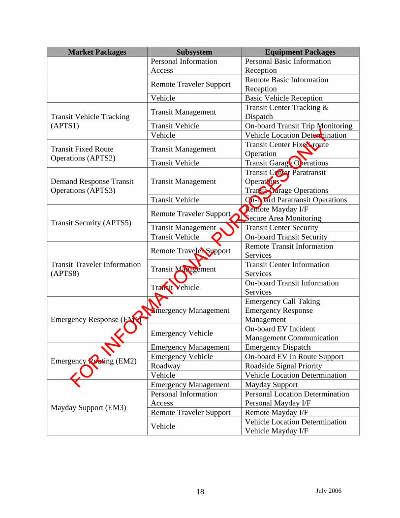
Archived Data (AD) ITS Data Mart 3.2.2 Subsystems and Equipment Packages This section summarizes the system functional requirements in terms of market packages, subsystems and equipment packages. A market package is implemented with interrelated equipment that often resides in different subsystems within the architecture frame work. To analyze the potential deployment variations, the identified market packages were “decomposed” to constituent levels. The portions of the market package capabilities that were allocated to each subsystem were defined as equipment packages. The list of primary market packages selected for the Shreveport/Bossier City region was used to identify the subsystems that were critical in developing the regional ITS architecture and to identify the equipment packages that made up the market packages. Table 3-3 shows
FOR INFORMATIO
NAL PURPOSES O
NLY

July 2006 17
the selected Shreveport/Bossier City regional market packages, the systems that are a part of the market packages and the equipment packages that make up the market packages.
Table 3-3: Shreveport/Bossier City Regional Market Packages
Market Packages Subsystem Equipment Packages Roadway Roadway Basic Surveillance Network Surveillance
(ATMS1) Traffic Management Collect Traffic Surveillance Traffic Maintenance
Roadway Roadway Signal Controls Surface Street Control (ATMS3) Traffic Management TMC Signal Controls
Traffic Maintenance Roadway Roadway Freeway Control
Freeway Control (ATMS4) Traffic Management TMC Freeway Control Traffic Maintenance
Roadway Roadway Traffic Information Dissemination Traffic Information
Dissemination (ATMS6) Traffic Management TMC Traffic Information Dissemination
Regional Traffic Control (ATMS7) Traffic Management TMC Regional Traffic Control
Emergency Management Emergency Response Management
Roadway Roadway Incident Detection Incident Management System (ATMS8)
Traffic Management TMC Incident Detection TMC Incident Dispatch Coordination/Communications
Emission Management Emergency Response Management
Roadway Roadway Incident Detection Emissions Monitoring and Management (ATMS 13)
Traffic Management TMC Incident Detection TMC Incident Dispatch Coordination/Communication
Roadway Standard Rail Crossing Standard Railroad Grade Crossing (ATMS13) Traffic Management HRI Traffic Management
Roadway Advanced Rail Crossing Advance Railroad Grade Crossing (ATMS 14) Traffic Management HRI Traffic Management Railroad Operations Coordination (ATMS 15) Traffic Management Railroad Operations Coordination
Roadway Roadway Environment MonitoringRoad Weather Information System (ATM 18) Traffic Management TMC Roadway Weather
Monitoring Broadcast Traveler Information (ATIS1)
Information Service Provider
Basic Information Broadcast
FOR INFORMATIO
NAL PURPOSES O
NLY
July 2006 18
Market Packages Subsystem Equipment Packages Personal Information Access
Personal Basic Information Reception
Remote Traveler Support Remote Basic Information Reception
Vehicle Basic Vehicle Reception
Transit Management Transit Center Tracking & Dispatch
Transit Vehicle On-board Transit Trip Monitoring Transit Vehicle Tracking (APTS1)
Vehicle Vehicle Location Determination
Transit Management Transit Center Fixed-route Operation Transit Fixed Route
Operations (APTS2) Transit Vehicle Transit Garage Operations
Transit Management Transit Center Paratransit Operations Transit Garage Operations
Demand Response Transit Operations (APTS3)
Transit Vehicle On-board Paratransit Operations
Remote Traveler Support Remote Mayday I/F Secure Area Monitoring
Transit Management Transit Center Security Transit Security (APTS5)
Transit Vehicle On-board Transit Security
Remote Traveler Support Remote Transit Information Services
Transit Management Transit Center Information Services
Transit Traveler Information (APTS8)
Transit Vehicle On-board Transit Information Services
Emergency Management Emergency Call Taking Emergency Response Management Emergency Response (EM1)
Emergency Vehicle On-board EV Incident Management Communication
Emergency Management Emergency Dispatch Emergency Vehicle On-board EV In Route Support Roadway Roadside Signal Priority Emergency Routing (EM2)
Vehicle Vehicle Location Determination Emergency Management Mayday Support Personal Information Access
Personal Location Determination Personal Mayday I/F
Remote Traveler Support Remote Mayday I/F Mayday Support (EM3)
Vehicle Vehicle Location Determination Vehicle Mayday I/F
FOR INFORMATIO
NAL PURPOSES O
NLY

July 2006 19
Market Packages Subsystem Equipment Packages
Archived Data Management
Government Reporting Systems ITS Data Repository Traffic and Roadside Data Archival
Emergency Management Emergency Data Collection Information Service Provider
ISP Data Collection
Roadway Roadside Data Collection Traffic Management Traffic Data Collection
ITS Data Mart (AD1)
Transit Management Transit Data Collection 3.2.3 Shreveport/Bossier City Regional ITS Physical Architecture
A physical architecture is a graphical representation of the ITS “system.” The physical architecture provides agencies with a physical representation (though not a detailed design) of the important ITS interfaces and major system components. A physical architecture takes the processes identified in the logical architecture and assigns them to subsystems. Physical architecture further identifies the system terminator inputs (sources) and system terminator outputs (destinations) for architecture flows into and out of the system. In addition, the data flows (from the logical architecture) are grouped together into architecture flows. The physical architecture includes the various transportation-related processing centers, roadside equipment, vehicle equipment, and other equipment used by the traveler to access the multitude of ITS services. The physical architecture coordinates overall system operations by defining interfaces between equipment and systems, which may be deployed by different organizational or operating agencies in the Shreveport/Bossier City region. Furthermore, the physical architecture framework defines what major transportation system elements do and how they interact to provide the user needs for the Shreveport/Bossier City region. Figure 3-3 presents the Shreveport/Bossier City regional ITS architecture.
FOR INFORMATIO
NAL PURPOSES O
NLY

July 2006 20
Figure 3-3: Shreveport/Bossier City Regional Physical Architecture
FOR INFORMATIO
NAL PURPOSES O
NLY

July 2006 21
This architecture represents the regional view of the ITS implementation. It does not take into account who/what organization would be responsible for implementing all the ITS systems. This architecture presents the “big picture” for the Shreveport/Bossier City region with regards to implementation. Detail descriptions of the subsystems can be found in the Shreveport/Bossier City Regional ITS Strategic Deployment Plan. 3.2.4 Recommended Standards for Shreveport/Bossier City Region More than ninety standards were identified as part of the National ITS architecture standard development activities. The task of working with public and private sector ITS community to develop these standards fell to seven different standards development organizations (SDOs). These SDOs include:
• American Association of State Highway and Transportation Officials (AASHTO); • American National Standards Institute (ANSI); • American Society for Testing and Materials (ASTM); • Institute of Electrical and Electronics Engineers (IEEE); • Institute of Transportation Engineers (ITE); • National Electrical Manufactures Association (NEMA); and • Society of Automotive Engineers (SAE).
Not all ITS standards will be applicable to the proposed ITS projects. Table 3-4 identifies the ITS standards that were considered relevant to the Shreveport/Bossier City region at the time the deployment plan was developed.
Table 3-4: Shreveport/Bossier City Regional ITS Standards Lead SDO Standard Name Document
ID Status*
AASHTO Simple transportation Management Framework (STMF) NTCIP 1101 P AASHTO Base Standard: Octet Encoding Rules (OER) NTCIP 1102 B AASHTO Simple Transportation Management Protocol (STMP) NTCIP 1103 U AASHTO Global Object Definitions NTCIP 1201 P AASHTO Object Definitions for Actuated Traffic Signal
Controller Units NTCIP 1202 P
AASHTO Object Definitions for Dynamic Message Signs NTCIP 1203 P AASHTO Object Definitions for Environmental Sensor Stations &
Roadside Weather Information System NTCIP 1204 P
AASHTO Data Dictionary for Closed Circuit Television (CCTV) NTCIP 1205 A AASHTO Object Definitions for DATA Collections NTCIP 1206 B AASHTO Ramp Meter Controller Objects NTCIP 1207 A AASHTO Objects Definitions for Video Switches NTCIP 1208 U AASHTO Object Definitions for Transportation Sensor System NTCIP 1209 B AASHTO Objects for Signal Systems Master NTCIP 1210 U AASHTO Objects for Signal Control Priority NTCIP 1211 U AASHTO Weather Report Message Set for ESS NTCIP 1301 U AASHTO Class B Profile NTCIP 2001 P
FOR INFORMATIO
NAL PURPOSES O
NLY

July 2006 22
Lead SDO Standard Name Document ID
Status*
AASHTO Point to Multi-Point Using RS-232 Subnetwork Profile NTCIP 2101 A AASHTO Subnetwork Profile for PMPP using FSK Modems NTCIP 2102 B AASHTO Subnet Profile for Point-to-Point Protocol Using RS232 NTCIP 2103 B AASHTO Subnetwork Profile for Ethernet NTCIP 2104 B AASHTO Transportation Transport Profile NTCIP 2201 B AASHTO Internet (TCP-IP and UDP/IP) Transport Profile NTCIP 2202 A AASHTO Application Profile for Simple Transportation
Management Framework (STMF) NTCIP 2301 A
AASHTO Application Profile for Trivial File Transfer Protocol NTCIP 2302 A AASHTO Application Profile for File Transfer Protocol (FTP) NTCIP 2303 A AASHTO Application Profile for Data Exchange ASN.1 (DATEX) NTCIP 2304 B AASHTO Application Profile for Common Object Request Broker
Architecture (CORBA) NTCIP 2305 U
AASHTO Information Profile for DATEX NTCIP 2501 U AASHTO Information Profile for CORBA NTCIP 2502 U ASTM ADMS Standard Guidelines ASTM AG U ASTM ADMS Data Dictionary Specifications ASTM DD U ASTM Standard Specification for 5.9 GHz Data Link Layer ASTM N/A U ASTM Standard Specification r 5.9 GHz Physical Layer ASTM N/A U ASTM Specification for Dedicated Short Range
Communication (DSRC) Data Link Layer: Medium Access and Logical Link Control
ASTM PS 105-99
P
ASTM Specification for Short Range Communication (DSRC) Physical Layer using Microwave in the 902-928 MHz
ASTM PS 111-98
P
EIA/CEA Data Radio Channel (DARC) System CEA/EIA-794
P
EIA/CEA Subcarrier Traffic Information Channel (STIC) System CEA/EIA-795
P
IEEE Standard for Traffic Incident Management Message Sets for Use by EMCs
IEEE P1512.1
U
IEEE Standard for Public Safety IMMS for Use by EMCs IEEE P1512.2
U
IEEE Standard for Emergency Management Data Dictionary IEEE P1512.a
U
IEEE Standard for Common Incident Management Message Sets (IMMS) for Use by EMCs
IEEE P1512-2000
P
IEEE Security/Privacy of Vehicle/RS Communications including Smart Card Communications
IEEE P1556 U
ITE Standard for Functional Level Traffic management Data Dictionary (TMDD)
ITE TM 1.03 B
ITE Message Sets for External TMC Communication (MS/ETMCC)
ITE TM 2.01 B
ITE TCIP – Common Public Transportation (CPT) Business Area Standard
NTCIP 1401 P
ITE TCIP – Incident Management (IM) Business Area Standard
NTCIP 1402 P
FOR INFORMATIO
NAL PURPOSES O
NLY

July 2006 23
Lead SDO Standard Name Document ID
Status*
ITE TCIP – Passenger Information (PI) Business Area Standard
NTCIP 1403 P
ITE TCIP – Scheduling/Run-cutting (SCH) Business Area Standard
NTCIP 1404 P
ITE TCIP – Spatial Representation (SP) Business Area Standard
NTCIP 1405 P
ITE TCIP – Onboard (OB) Business Area Standard NTCIP 1406 P ITE TCIP – Control Center (CC) Business Area Standard NTCIP 1407 P SAE ISP – Vehicle Location Referencing Standard SAE J1746 P SAE On-Board Land Vehicle Mayday Reporting Interface SAE J2313 P SAE Data Dictionary for Advanced Traveler Information
System (ATIS) SAE J2353 P
SAE Message Set for Advanced Traveler Information (ATIS) SAE J2354 P SAE Standard for navigation and Route Guidance Function
Accessibility While Driving SAE J2364 B
SAE Standard for ATIS Message Sets Delivered Over Bandwidth Restricted Media
SAE J2369 P
SAE ITS In-Vehicle Message Priority SAE J2395 A SAE Measurement for Driver Visual Behavior Using Video
Based Methods (Def. & Meas.) SAE J2396 P
SAE Adaptive Cruise Control: Operating Characteristics and User Interface
SAE J2399 B
SAE Forward Collision Warning: Operating Characteristics and User Interface
SAE J2400 U
SAE Rules for Standardizing Street Names and Route IDs SAE J2529 B SAE Messages for Handling Strings and Look-Up Tables in
ATIS Standards SAE J2540 A
*Status (as of December 31, 2001): P-Published, B-In. Ballot, A-Approved, and U-Under Development 3.3 Shreveport/Bossier City ITS Deployment Immediate Term Phase 2 Project As described in Chapter 1 of this document, the purpose of this project is to improve traffic operations and safety along this major arterial by monitoring vehicular traffic movement and traffic signal operations. Traffic monitoring and traffic signal management will be accomplished with the cooperation of LADOTD District 04 and the City of Shreveport. New ITS technologies will enhance the existing traffic signal system and traffic management capabilities of the participating agencies. These new ITS technologies will be deployed and integrated with existing ITS technologies and the ITS technologies currently designed and undergoing deployment (Shreveport/Bossier City ITS Near Term Phases 1&3A). These ITS technologies will provide: traffic monitoring, traffic signal upgrades, and video image monitoring.
FOR INFORMATIO
NAL PURPOSES O
NLY
July 2006 24
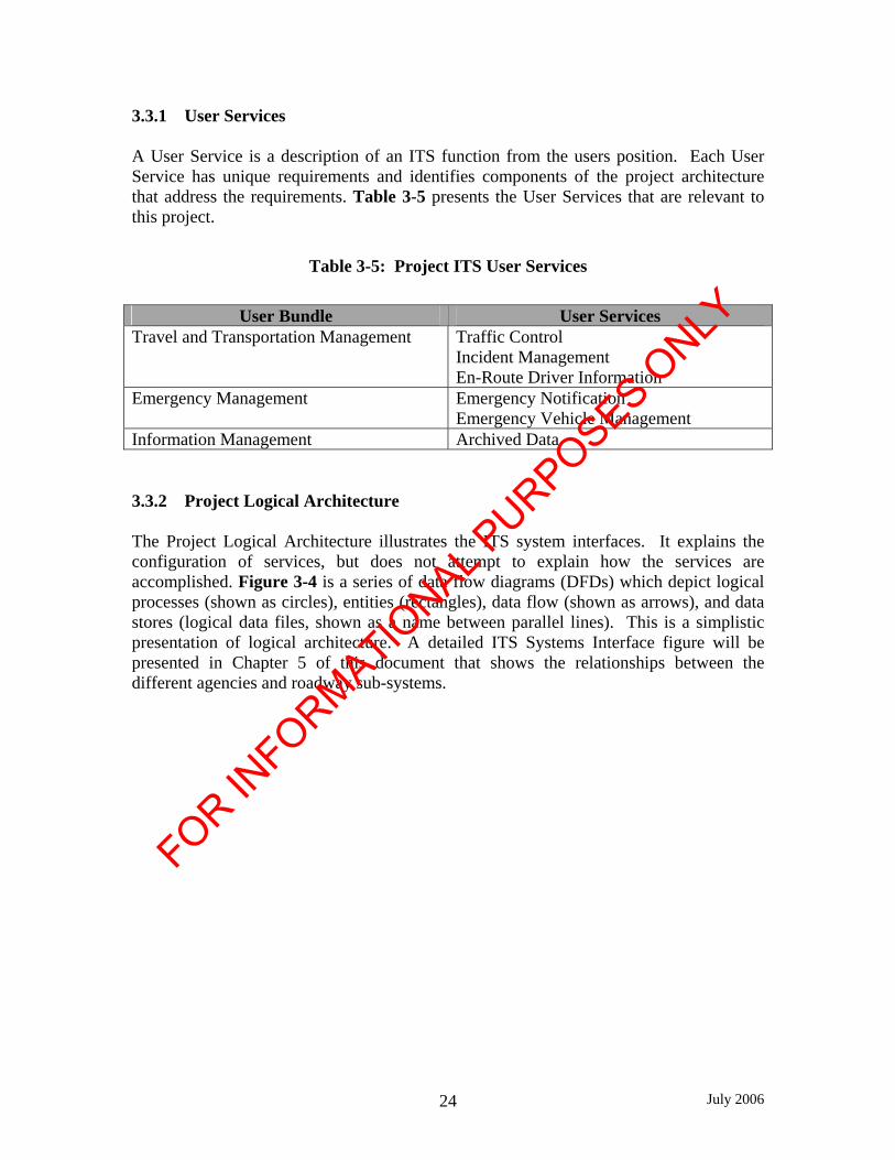
3.3.1 User Services A User Service is a description of an ITS function from the users position. Each User Service has unique requirements and identifies components of the project architecture that address the requirements. Table 3-5 presents the User Services that are relevant to this project.
Table 3-5: Project ITS User Services
User Bundle User Services Travel and Transportation Management Traffic Control
Incident Management En-Route Driver Information
Emergency Management Emergency Notification Emergency Vehicle Management
Information Management Archived Data 3.3.2 Project Logical Architecture
The Project Logical Architecture illustrates the ITS system interfaces. It explains the configuration of services, but does not attempt to explain how the services are accomplished. Figure 3-4 is a series of data flow diagrams (DFDs) which depict logical processes (shown as circles), entities (rectangles), data flow (shown as arrows), and data stores (logical data files, shown as a name between parallel lines). This is a simplistic presentation of logical architecture. A detailed ITS Systems Interface figure will be presented in Chapter 5 of this document that shows the relationships between the different agencies and roadway sub-systems.
FOR INFORMATIO
NAL PURPOSES O
NLY

July 2006 25
Figure 3-4: Project Logical Architecture
3.3.3 Project Physical Architecture
The Project Physical Architecture illustrates the important ITS interfaces and the major system components. The physical architecture assigns processes from the logical architecture to subsystems, and group’s data flows from the logical architecture into architecture flows. These flows and corresponding communication requirements define the interfaces which are a main focus of the project ITS standards. Figure 3-5 illustrates the project physical architecture under consideration. It depicts the overall understanding of the physical architecture components associated with the project. The physical architecture for this project will be further developed and detailed with required information flows in Chapter 5 of this document.
FOR INFORMATIO
NAL PURPOSES O
NLY

July 2006 26
Figure 3-5: Project Physical Architecture
3.3.4 Project Market Packages
A Market Package is a breakdown of an ITS service that is specifically tailored to meet real world transportation needs and address associated issues. There are currently over 60 Market Packages defined in the National ITS Architecture designed for implementation separately or in combination to provide an integrated system. For this project there are three categories of Market Packages that are applicable: Advanced Traffic Management Systems (ATMS), Advanced Traffic Information Systems (ATIS) and Emergency Management (EM). The need and application for these market packages will be further developed and presented in the subsequent Chapters 4
FOR INFORMATIO
NAL PURPOSES O
NLY

July 2006 27
and 5 of this document. Table 3-6 presents the recommended Market Packages for deployment.
Table 3-6: Project Market Packages
ATMS EM AD
Network Surveillance Emergency Response ITS Data Mart Surface Street Control Emergency Routing Freeway Control Traffic Information Dissemination
Incident Management System
Standard Railroad Grade Crossing
Advanced Railroad Grade Crossing
Railroad Operations Coordination
3.3.5 Relevant Project ITS Standards
The development of system standards is essential for the interoperability and integration of any ITS project. These standards provide for a continuity of understanding in the design and implementation of ITS projects. Standards are critical if statewide ITS system integration and sharing of information between different transportation agencies is to be achieved. Table 3-7 presents general ITS standards applicable to this project.
FOR INFORMATIO
NAL PURPOSES O
NLY

July 2006 28
Table 3-7: ITS Standards
Standard Development
Organization Applicable Architecture
Interfaces Key ITS Standards for Project
Architecture Traffic Management Center to Field Devices.
National Transportation Communications for ITS Protocol (NTCIP). AASHTO
ITE NEMA Traffic Signal Controllers. Advanced Transportation
Controllers (ATC).
ITE Traffic Management Center to Center.
Traffic Management Data Dictionary (TMDD). Message Sets for External Traffic Management Center Communications (MS/ETMCC).
Emergency Management Center to Center.
Standard for Incident Management Sets (IMSS) for Use by Emergency Management Centers. IEEE
General. Standard for Data Dictionaries for ITS.
ASTM Interfaces - Archived Data Management Center.
Standard Guide for Archiving and Retrieving ITS Data.
Traveler Information (Information Services Provider (ISP) Interfaces).
Advanced Traveler Information System (ATIS) Data Dictionary. Advanced Traveler Information Systems (ATIS) Core Message List and Data Dictionary. SAE
Location Referencing. Location Referencing Standards.
Because of its significance in contributing to the interoperability of ITS systems and equipment, it is appropriate to elaborate on NTCIP standards. NTCIP is the national transportation communications standard which defines a family of general-purpose protocols that support all types of computer systems and field devices used in transportation management. Applications for NTCIP is divided into two categories– center-to-field and center-to-center. Center-to-field involves devices at the roadside or on agency-owned vehicles, communicating with management software on a central computer. Center-to-center applications usually involve computer-to-computer communications where the computers can be in the same room, in management centers operated by adjacent agencies, or across the country. Detailed information regarding standards applicable to this project is presented in Chapter 8 of this document.
FOR INFORMATIO
NAL PURPOSES O
NLY

July 2006 29
3.3.6 Integrating Project Architectures with Existing Regional Architectures
The Project Architecture (and the project design and operations that comes from it) must be integrated with the existing ITS Shreveport/Bossier City ITS Deployment Immediate Term Phase 1 and the ITS system operations that will be deployed as part of Shreveport/Bossier City ITS Phases 1 & 3A. The Project Logical Architecture depicts the data flows between the different elements that comprise the transportation and traffic universe operating within the project limits. The relationships and interaction identified for this project recognizes similar data flows identified in the Shreveport/Bossier City ITS regional architecture. The interactions and participant commitments associated with these relationships will be developed and presented in detail in Chapters 4-6 of this System Engineering analysis document. The individual elements that comprise the Project Physical Architecture are reflective of similar elements shown for both regional physical architectures. This is particularly true for the communications element where it is anticipated that existing communication infrastructure will support the communication needs associated with the Project Architecture. Chapter 4.0 Concept of Operations
The Concept of Operations (ConOps) describes how the proposed system will work once it is built. Therefore, ConOps relates directly to the Operations and Maintenance phase of the project life-cycle, and the system must be designed to satisfy it. ConOps describes the roles and responsibilities for operations and maintenance of the various system users, and must be consistent with the Shreveport/Bossier City Regional ITS Architecture. The ConOps may describe more than the actual elements that will be deployed as part of this phase of the project, as it attempts to be comprehensive addressing all anticipated future needs. Where appropriate, the elements that are proposed to be implemented as part of this project will be marked in a manner to clearly note such inclusion in the project design. For example, the Bert Kouns project is planned for deployment along with other project phases which will deploy ITS tools for adjacent freeway segments. While the Bert Kouns project is not a full deployment of freeway management tools (e.g., no dynamic message signs proposed on LA 526), all the ITS tools in the region must work together with data sharing in a coordinated fashion. Therefore, for completeness sake, the broader regional view is presented in the ConOps. 4.1 Purpose The Concept of Operations must support the Needs Analysis from Chapter 2 and the User Services identified in Chapter 3. The general purpose is to improve traffic operations and safety in the project area, and support regional traffic incident management efforts.
FOR INFORMATIO
NAL PURPOSES O
NLY

July 2006 30
4.2 Stakeholders
The key agencies or stakeholders responsible for Traffic Operations and Incident Management in the project limits are:
1. The Louisiana Department of Transportation and Development – District 04, (District 04);
2. City of Shreveport – Department of Operational Services, Office of Public Works (Shreveport PW);
3. City of Shreveport – Police Department (SPD); 4. Louisiana State Police – Troop G (LSP Troop G); 5. Caddo Parish Sheriff’s Office (CSO); 6. Caddo Parish Communications District (911); 7. Parish of Caddo Public Works (Caddo PW); and 8. LADOTD Motorist Assistance Patrol (MAP).
Other potential stakeholders include local fire departments and other emergency responders (ambulance, medical services, towers, hazmat), and the statewide emergency management stakeholders located at the LADOTD Headquarters’ Annex in Baton Rouge. The roles and responsibilities of each stakeholder will conform to the jurisdictions of each stakeholder and the Traffic Incident Management Plan for Shreveport/Bossier City. The jurisdictions are described in Section 2.3. 4.3 Functions and Processes This project is a phase of ITS deployment elements within the region. This project will improve traffic operations along the LA 526 corridor and expand the network to improve incident management in the region. As part of the Traffic Incident Management Plan, sections of Bert Kouns have already been designated as an alternate route for I-20, I-49, and LA 3132 per the Alternate Route Plan ARP Field Guide by Traffic Incident Management System Committee, 2003. This project will build upon the existing systems and processes. The Concept of Operations will describe the various functions required to meet the objective, and the corresponding processes to perform each function. For this project, each function consists of the steps to operate the traffic signals and other traffic management systems and ITS components during incidents. Figures 4.1a-4.1c sequentially present the traffic incident management response, as well as for “normal” conditions when there is no ongoing incident conditions, followed by descriptions of the processes required for each function.
FOR INFORMATIO
NAL PURPOSES O
NLY

July 2006 31
Figure 4-1a: Concept of Operations Functions – Incident Management
D. Notify to activate route diversion.
E. Provide motorists information on freeway approaches
F. Provide motorists information on alternate
G. Adjust signal timing on alternate.
H. Assess conditions and adjust controls.
I. Notify to stop route diversion.
A. Detect Traffic Incident
B. Verify/ Respond to Traffic Incident
C. Assess Traffic Incident Type and Duration
FOR INFORMATIO
NAL PURPOSES O
NLY

July 2006 32
Figure 4-1b: Concept of Operations Functions – Signal System Operations
Figure 4-1c: Concept of Operations Functions – Maintenance and Archived Data A. Detect Incident
Process Unexpected traffic incidents are detected by either public phone calls, ITS surveillance equipment (during verification of another incident), or upon routine patrol by a local law enforcement agency, LSP or LADOTD personnel. Whichever source of detection, the traffic incident is reported to the Caddo Parish Communications District, 911 (houses and dispatches both CSO and SPD), who will enter data into their desk log.
J. Collect traffic data
K. Develop signal timing plans for various situations (peaks/events)
L. Schedule timing operations
M. Adjust schedule timing operations as needed
N. Monitor for incidents and system faults
O. Adjust signal timings as needed
P. Repair system faults
Q. Return to normal scheduled operations
R. Log and archive all communications and system activities
S. Generate maintenance reports for each field element during system faults.
FOR INFORMATIO
NAL PURPOSES O
NLY

July 2006 33
B. Verify/Respond to Incident Scene Process
An incident may be verified by remote controlled visual surveillance, the field location source if reported by a local law enforcement agency, LSP or LADOTD personnel, or upon the arrival of a responding stakeholder to the traffic incident site. C. Assess Incident Type and Severity
Process The SPD Officer or CSO Deputy arriving at the scene will assess and classify the traffic incident type to identify additional response needs to the Shreveport PD or Sheriff’s Department Dispatcher, and assesses the severity of the traffic incident (minor, intermediate, or major) to estimate the duration of the incident. The responding agency dispatcher will make the notification to LADOTD via a phone call to the LADOTD District 04 Interim Traffic Management Center (District 04 TMC)* during hours of operations for major incidents that will result in a long-term roadway closure. * Note: District 04 TMC and/or the statewide LADOTD TMC in the LADOTD Headquarters Annex Baton Rouge (LADOTD HQ TMC) will have staff available to display messages on information dissemination devices and/or provide guidance if the District 04 TMC is not in operation. Hereafter, District 04 TMC shall refer to the District 04 TMC, the LADOTD HQ TMC or the on-call staff depending on time of day operations and TMCs’ staffing unless specified otherwise.
D. Notification to activate route diversions. Process The senior SPD Officer or senior CSO Deputy, acting as the Incident Commander on the scene in charge of the incident management process, will determine the need for a traffic detour based on the estimated traffic incident duration. The Incident Commander will contact all affected agencies through his or her dispatcher, advising that traffic is being diverted. It is again noted that segments of LA 526 (Bert Kouns) have been designated as pre-approved alternative routes for LA 3132, I-20 and I-49 as part of the regional Traffic Incident Management Plan. The Incident Commander’s dispatcher will make the notification to the District 04 TMC via a phone call. The Incident Commander will advise implementation of the alternate route (Bert Kouns) and any resources required (i.e. personnel, courtesy patrol services, ITS equipment, barricades, barrels, and detour signs, if available). The police can divert traffic without requesting assistance from LADOTD.
FOR INFORMATIO
NAL PURPOSES O
NLY
July 2006 34
Note: Functions E-G may occur simultaneously.
E. Provide information dissemination for motorists upstream of full directional closure incident on freeway, to identify incident impact and alternate route(s).
Process The dissemination devices on the freeways (e.g., DMS) will support the ability to direct motorists to the designated alternate route, and are integrated into the LADOTD TMCs. The LADOTD is responsible for the operations and maintenance of these information dissemination devices. The District 04 TMC shall disseminate non-specific traffic incident messages to available DMS as soon as traffic incidents are detected, and disseminate a revised message once the incident is verified and assessed. The District 04 TMC will have the ability to display customized messages on the DMS. The message shall warn motorists of a highway closure and directional information for the diversion if conditions so require. In the case of a traffic incident diversion, the dissemination devices in advance of the exit for the alternate route will direct motorists to use the alternate route. District 04 TMC is responsible for entering advisory data in to the 511 CARS system for motorist advisory information when accident or traffic incident notification is provided by CSO dispatch or SPD dispatch. However, if LSP dispatch receives initial notification, LSP dispatch shall enter advisory data in the 511 CARS system. All traffic control response information will be shared and coordinated between Districts 04, SPD, Shreveport PW, and CSO through CAD (SPD & CSO only), radio communications (all except District 04), otherwise via telephone. F. Provide route guidance information along alternate route.
Process District 04, City of Shreveport PW, SPD and/or CSO in coordination provide route guidance along the alternate route. The LADOTD is responsible for the operations and maintenance of all route guidance signing along the alternate route. All traffic control response information will be shared and coordinated between Districts 04, SPD, Shreveport PW, and CSO through CAD (SPD & CSO only), radio communications (all except District 04), otherwise via telephone.
FOR INFORMATIO
NAL PURPOSES O
NLY

July 2006 35
G. Adjust signalized intersection operations on alternate route based on conditions created by diverting traffic.
Process Traffic signal equipment along the alternate routes provide real-time control capability to the District TMC and City of Shreveport Traffic Operations Centers (TOC), including vehicle sensors, to permit actuated operations and controllers integrated with signal systems at the City of Shreveport TOC and District TMC. The responsibility for the operations and maintenance of the traffic signals within the project limits is identified in Section 2.3. The responsible agency for the City of Shreveport, the City of Shreveport PW, shall adjust signal timings based on real-time conditions. All signal timing information will be shared and coordinated between District 04 and the City of Shreveport via correspondence (email or mailed letter), otherwise via telephone. H. Monitor traffic conditions along project limits corridor to assess effectiveness and
adjust traffic controls. Process Traffic monitoring equipment will provide real-time monitoring capability from the City of Shreveport TOC and District 04 TMC, including vehicle sensors and video surveillance, along LA 526, with all sensors and cameras integrated into District 04 TMC and the City of Shreveport TOC. The LADOTD is responsible for the operations and maintenance of all monitoring equipment within the project limits (Note: City of Shreveport is responsible for maintaining traffic signals). District 04 is responsible for the operations and maintenance of the traffic monitoring equipment in the district. The agency that entered the initial advisory data into 511 CARS system, whether LSP or District 04 TMC, will adjust advisory information as needed based on real time data. District 04 TMC will adjust DMS messages as required based on real time data. All vehicle sensor information and surveillance video will be shared between LADOTD Districts 04 and City of Shreveport. City of Shreveport TOC will adjust traffic control based on real-time conditions during the traffic incident response and clearance stages. Since conditions can vary during the incident, an arrow from Block “H” back to Block “D” in Figure 4-13 indicates the iterative nature of these processes.
FOR INFORMATIO
NAL PURPOSES O
NLY

July 2006 36
I. Notification of when to de-activate route diversions. Process The Incident Commander in charge of the traffic incident scene shall determine when to de-activate the traffic detour, and contact all affected agencies through his or her dispatcher to request that the route diversion be discontinued. The Incident Commander’s dispatcher will make the call to the District 04 TMC. District 04 TMC will remove messages for the information dissemination devices advising of closures and detour routes. Also, the Incident Commander’s dispatcher will contact other police departments with jurisdictions along the alternate routes to remove any deployed traffic control at respective intersections. The Incident Commander’s dispatcher will call or radio the City of Shreveport TOC to restore timing at the affected traffic signals. J. Collect traffic data
Process Signal system operating agencies are to collect traffic volumes, turning count data, and travel time runs along with required geometric information for various timeframes to be used as input for signal timing analysis.
K. Develop signal timing plans for various situations (peaks/events). Process Signal system operating agencies are to develop signal timing plans to cover various situations that bring unique traffic conditions, including peak periods (i.e. AM / PM commuter peaks, other weekday / weekend peaks) throughout each day, and both planned or unplanned events (i.e. roadwork, incidents). Depending upon situations and roadway geometrics, signal timing plans may need to be coordinated over adjacent intersection traffic signals. L. Schedule timing operations Process Signal system operating agencies are to develop time-of-day schedules for various timing plans to be implemented at each of the traffic signals that correspond to expected traffic conditions, promoting safe and efficient traffic flow.
FOR INFORMATIO
NAL PURPOSES O
NLY

July 2006 37
M. Adjust schedule timing operations as needed. Process Signal system operating agencies should adjust signal timing plans and time-of-day schedules based on any inefficiencies discovered during operations. This may require revising previous functional steps L-N, depending on the complexities. N. Monitor for incidents and system faults. Process Signal system operating agencies (during established operation hours) should monitor traffic flow conditions in real-time for possible incidents that may disrupt traffic flow, or system faults that require corrective action. O. Adjust signal timings as needed. Process Signal system operating agencies should adjust signal timing operations in real-time during incident situations to mitigate impacts to traffic flow. P. Repair system faults. Process Signal system operating agencies should troubleshoot and repair system faults discovered in the operations of the signal systems. Q. Return to normal scheduled operations. Process Signal system operating agencies should return systems to normal operations upon completion of incident or system fault situation. R. Log and archive all communications, data collection and system activities.
Process All SPD and CSO activities and correspondence will be logged in the police CAD system, with the information archived to be used to measure incident clearance times for future references. All LADOTD radio communications shall be logged and archived. All LADOTD and Shreveport PW system activities will be logged by the specific system. The District 04 TMC operator and field technicians responding to incident events will
FOR INFORMATIO
NAL PURPOSES O
NLY

July 2006 38
maintain a log of their activities. All traffic data collected by the LADOTD and City of Shreveport traffic management systems shall be archived. S. Generate maintenance reports for each field element during system faults. Process Each ITS field element will have capability of fault monitoring with maintenance reports generated that detail the fault. These will be generated by the respective system at the District 04 TMC, with copies distributed to each responsible maintenance unit in the district. Traffic signal system fault monitoring maintenance reports will be generated detailing the fault to both the District 04 TMC and the City of Shreveport TOC. Chapter 5.0 System Requirements Definitions
This stage of the Systems Engineering process focuses on ensuring that the requirements defined for the system state what needs to be done, rather than how it should be done. Systems Engineering also works at ensuring that the requirements defined are clear, complete, and correct. 5.1 Functions the System Will Perform The Concept of Operations identified the following functions to be performed from the project:
A. Detect traffic incident. B. Verify/respond to traffic accident scene. C. Assess traffic incident type and duration. D. Notification to activate route diversions. E. Provide information dissemination for motorists upstream of full directional
closure incident on corridor route, to identify incident impact and alternate route(s).
F. Adjust signalized intersection operations on alternate route based on conditions created by diverting traffic.
G. Monitor traffic conditions along the corridor diversion to assess effectiveness and adjust traffic controls.
H. Notification of when to de-activate route diversions. I. Collect traffic data. J. Develop signal timing plans for various situations (peaks/events). K. Schedule timing operations. L. Adjust schedule timing operations as needed. M. Monitor for incidents and system faults. N. Adjust signal timings as needed. O. Repair system faults. P. Return to normal scheduled operations.
FOR INFORMATIO
NAL PURPOSES O
NLY
July 2006 39
5.2 Identify System Components The system components required for this project based upon the functions identified above are as follows:
• Ability to modify signalized intersection control along arterial routes from remote locations.
• Real-time traffic flow information for various segments along project corridor routes to identify congestion.
• Data archival of traffic flow and traffic incident information for planning and safety management applications.
• Video surveillance at key locations along the project corridor to verify traffic incidents and improve traffic incident responses.
• Ability to provide motorist advisory via roadside dissemination devices. • Integrate field elements to appropriate TMC and TOC. • Ability to communicate and share information with other traffic management
centers and emergency responders. 5.3 System Interfaces Each system component above is presented below with the system interfaces required for information exchange. Basically, the system interfaces are consistent with the national and regional ITS architectures described in Chapter 3, and as reflected in the Concept of Operations in Chapter 4. All roadway subsystem elements must interface with the LADOTD District 04 Interim Traffic Management Center (District 04 TMC), as it is done with existing ITS elements. The District 04 TMC is linked with the City of Shreveport Interim Traffic Operations Center (TOC) for information sharing as required in the statewide and regional ITS architecture, as well as linked to the SPD, CSO and LSP Troop G Headquarters. Figure 5-1 illustrates system interfaces.
FOR INFORMATIO
NAL PURPOSES O
NLY

July 2006 40
Figure 5-1: System Interfaces
5.4 Project Architecture Fig. 5-2 presents the proposed project architecture, which is based on the associated portions of the regional architectures, and is customized to serve this project. Components and information flows that are to be deployed in this project phase are highlighted in yellow. Table 5-1 presents and details the information flows in the project architecture with the associated components and information flows to be deployed highlighted in yellow.
Motorist Advisory Elements
Traffic Signal Control
Traffic Flow
Detection
Traffic Flow
Detection
Video Surveillance
Video Surveillance
LADOTD District 04
Traffic Management
Center
City of Shreveport
Traffic Operations
Center
LSP Troop GHeadquarters
Dispatch
Shreveport Police
Headquarters Dispatch
Data Archival System
ITS Maintenance
Traveler Information
ITS Maintenance
Traveler Information
Traffic Signal Control
Data Archival System
Other Local Traffic Management and Emergency Response (including Caddo Sheriff)
Statewide ATM/EOC
FOR INFORMATIO
NAL PURPOSES O
NLY

July 2006 41
Figure 5-2: Project Architecture
FOR INFORMATIO
NAL PURPOSES O
NLY

July 2006 42
Table 5-1: Project Architecture Information Flows
Subsystem IdentifierNumber Information Flow Arrow Subsystem/Terminator
Other Emergency Management in Shreveport/Bossier City Region
1
Incident Report Notification & Resource Requests
Dispatcher
Other Emergency Management in Shreveport/Bossier City Region
2 Incident Report Notification and Resource Responses
Dispatcher
Other Emergency Management in Shreveport/Bossier City Region
3 Incident Status Other Emergency Management Vehicle
Other Emergency Management in Shreveport/Bossier City Region
4 Incident Command Information Other Emergency
Management Vehicle
Other Emergency Management Vehicle 5
Incident Report Notification, Status and Requests
Field Agent
Other Emergency Management Vehicle 6
Incident Report Response, Status and Resource Requests
Field Agent
Emergency Management Caddo Communications District
7 Incident Report
Other Emergency Management in Shreveport/Bossier City Region
Emergency Management Caddo Communications District
8 Incident Response Coordination
Other Emergency Management in Shreveport/Bossier City Region
Emergency Management Caddo Communications District
9
Incident Report, Status, Command Information, and Response Coordination
Emergency Management Shreveport Police
Emergency Management Caddo Communications District
10
Incident Report, Status, Command Information, and Response Coordination
Emergency Management Caddo Sheriff
FOR INFORMATIO
NAL PURPOSES O
NLY

July 2006 43
Subsystem IdentifierNumber Information Flow Arrow Subsystem/Terminator
Emergency Management Caddo Sheriff 11 Incident Status Emergency Vehicle
Caddo Sheriff Emergency Management Caddo Sheriff 12 Incident Command
Information Emergency Vehicle Caddo Sheriff
Emergency Vehicle Caddo Sheriff 13
Incident Report Notification, Status and Requests
Caddo Sheriff Deputy
Emergency Vehicle Caddo Sheriff 14
Incident Report Response, Status and Resource Requests
Caddo Sheriff Deputy
Emergency Vehicle Caddo Sheriff 15
Incident Report Notification, Status and Requests
Caddo Sheriff Dispatch
Emergency Vehicle Caddo Sheriff 16
Incident Report Response, Status and Resource Requests
Caddo Sheriff Dispatch
Emergency Management Shreveport Police 17 Incident Status Emergency Vehicle
Shreveport Police Emergency Management Shreveport Police 18 Incident Command
Information Emergency Vehicle Shreveport Police
Emergency Vehicle Shreveport Police 19
Incident Report Notification, Status and Requests
Shreveport Police Officer
Emergency Vehicle Shreveport Police 20
Incident Report Response, Status and Resource Requests
Shreveport Police Officer
Emergency Vehicle Shreveport Police 21
Incident Report Notification, Status and Requests
Shreveport Police Dispatch
Emergency Vehicle Shreveport Police 22
Incident Report Response, Status and Resource Requests
Shreveport Police Dispatch
Emergency Management LSP Troop G 21 Incident Status Emergency Vehicle LSP
Troop I Emergency Management LSP Troop G 22 Incident Command
Information Emergency Vehicle LSP Troop I
Emergency Management Caddo Communications District
23 Incident Report Response, Status and Resource Requests
Communications Officer
Emergency Management Caddo Communications District
24 Incident Report Response, Status and Resource Requests
Communications Officer
FOR INFORMATIO
NAL PURPOSES O
NLY

July 2006 44
Subsystem IdentifierNumber Information Flow Arrow Subsystem/Terminator
Emergency Management Caddo Communications District
25
Incident Report, Status, Command Information, and Response Coordination
Emergency Management LSP Troop G
Emergency Management LSP Troop G 26 Incident Command
Information Emergency Vehicle LSP Troop G
Emergency Management LSP Troop G 27 Incident Command
Information Emergency Vehicle LSP Troop G
Emergency Vehicle LSP Troop G 28
Incident Report Notification, Status and Requests
LSP Field Trooper
Emergency Vehicle LSP Troop G 29
Incident Report Response, Status and Resource Requests
LSP Field Trooper
Emergency Vehicle LSP Troop G 30
Incident Report Notification, Status and Requests
LSP Desk Sergeant
Emergency Vehicle LSP Troop G 31
Incident Report Response, Status and Resource Requests
LSP Desk Sergeant
Traffic Management City of Shreveport 32 Incident Information Emergency Management
Shreveport Police Traffic Management City of Shreveport 33 Resource Request Emergency Management
Shreveport Police Traffic Management City of Shreveport 34 Current Network
Conditions Emergency Management Shreveport Police
Traffic Management City of Shreveport 35 Resource
Deployment Emergency Management Shreveport Police
Traffic Management LADOTD Dist. 04 36 Incident Information Emergency Management
Shreveport Police Traffic Management LADOTD Dist. 04 37 Resource Request Emergency Management
Shreveport Police Traffic Management LADOTD Dist. 04 38 Current Network
Conditions Emergency Management Shreveport Police
Traffic Management LADOTD Dist. 04 39 Resource
Deployment Emergency Management Shreveport Police
Traffic Management LADOTD Dist. 04 40 Incident Information Emergency Vehicle Caddo
Sheriff Traffic Management LADOTD Dist. 04 41 Resource Request Emergency Vehicle Caddo
Sheriff Traffic Management LADOTD Dist. 04 42 Current Network
Conditions Emergency Vehicle Caddo Sheriff
FOR INFORMATIO
NAL PURPOSES O
NLY

July 2006 45
Subsystem IdentifierNumber Information Flow Arrow Subsystem/Terminator
Traffic Management LADOTD Dist. 04 43 Resource
Deployment Emergency Vehicle Caddo Sheriff
Traffic Management LADOTD Dist. 04 44 Incident Information Emergency Management
LSP Troop G Traffic Management LADOTD Dist. 04 45 Resource Request Emergency Management
LSP Troop G Traffic Management LADOTD Dist. 04 46 Current Network
Conditions Emergency Management LSP Troop G
Traffic Management LADOTD Dist. 04 47 Resource
Deployment Emergency Management LSP Troop G
Traffic Management LADOTD Dist. 04 48 Traffic Information
Coordination Other Traffic Management
Traffic Management LADOTD Dist. 04 49 Traffic Control
Coordination Other Traffic Management
Other Traffic Management 50
Traffic Information and Control Requests
Operator
Other Traffic Management 51 Traffic Control
Responses Operator
Traffic Management LADOTD Dist. 04 52 Traffic Information
Coordination LADOTD HQ Traffic Management
Traffic Management LADOTD Dist. 04 53 Traffic Control
Coordination LADOTD HQ Traffic Management
LADOTD HQ Traffic Management 54
Traffic Information and Control Requests
Operator
LADOTD HQ Traffic Management 55 Traffic Control
Responses Operator
Traffic Management LADOTD Dist. 04 56
Equipment Package Status Information and Resource Requests
TMC Operator
Traffic Management LADOTD Dist. 04 57
Information Monitoring and Control Requests of all Equipment Packages
TMC Operator
Traffic Management LADOTD Dist. 04 58 Surveillance
Equipment Status Roadway LADOTD Dist. 04
Traffic Management LADOTD Dist. 04 59 Traffic Flow Data Roadway LADOTD Dist.
04 Traffic Management LADOTD Dist. 04 60 CCTV Images Roadway LADOTD Dist.
04
FOR INFORMATIO
NAL PURPOSES O
NLY

July 2006 46
Subsystem IdentifierNumber Information Flow Arrow Subsystem/Terminator
Traffic Management LADOTD Dist. 04 61 DMS Status Roadway LADOTD Dist.
04 Traffic Management LADOTD Dist. 04 62 CCTV Control Roadway LADOTD Dist.
04 Traffic Management LADOTD Dist. 04 63 Signal Control Roadway LADOTD Dist.
04 Traffic Management LADOTD Dist. 04 64 DMS Control Roadway LADOTD Dist.
04 Traffic Management LADOTD Dist. 04 65 Signal Control Status Roadway LADOTD Dist.
04 Traffic Management LADOTD Dist. 04 66 Request for Signal
Right-of-Way Roadway LADOTD Dist. 04
Roadway LADOTD Dist. 04 67 Status Requests and
Control Commands Dynamic Message Signs
Roadway LADOTD Dist. 04 68 Status Dynamic Message Signs
Roadway LADOTD Dist. 04 69 Status Requests and
Control Commands Vehicle Sensors
Roadway LADOTD Dist. 04 70 Status Vehicle Sensors
Roadway LADOTD Dist. 04 71 Status Requests and
Control Commands CCTV Cameras
Roadway LADOTD Dist. 04 72 Status CCTV Cameras
Roadway LADOTD Dist. 04 73 Status Requests and
Control Commands Traffic Signal Controllers
Roadway LADOTD Dist. 04 74 Status Traffic Signal Controllers
Traffic Management LADOTD Dist. 04 75
Traffic Management Information Status and Activity Requests of all Equipment Packages
Traffic Management City of Shreveport
Traffic Management City of Shreveport 76
Equipment Package Status Information and Resource Requests
TOC Operator
Traffic Management City of Shreveport 77
Information Monitoring and Control Requests of all Equipment Packages
TOC Operator
Traffic Management City of Shreveport 78 Surveillance
Equipment Status Roadway City of Shreveport
FOR INFORMATIO
NAL PURPOSES O
NLY

July 2006 47
Subsystem IdentifierNumber Information Flow Arrow Subsystem/Terminator
Traffic Management City of Shreveport 79 Traffic Flow Data Roadway
City of Shreveport Traffic Management City of Shreveport 80 CCTV Control Roadway
City of Shreveport Traffic Management City of Shreveport 81 Signal Control Roadway
City of Shreveport Traffic Management City of Shreveport 82 CCTV Images Roadway
City of Shreveport Traffic Management City of Shreveport 83 Signal Control Status Roadway
City of Shreveport Traffic Management City of Shreveport 84 Request for Signal
Right-of-Way Roadway City of Shreveport
Traffic Management City of Shreveport 85 DMS Status Roadway
City of Shreveport Roadway City of Shreveport 86 Status Requests Dynamic Message Signs
Roadway City of Shreveport 87 Status Dynamic Message Signs
Roadway City of Shreveport 88 Status Requests and
Control Commands Vehicle Sensors
Roadway City of Shreveport 89 Status Vehicle Sensors
Roadway City of Shreveport 90 Status Requests CCTV Cameras
Roadway City of Shreveport 91 Status CCTV Cameras
Roadway City of Shreveport 92 Status Requests and
Control Commands Traffic Signal Controllers
Roadway City of Shreveport 93 Status Traffic Signal Controllers
Traffic Management LADOTD Dist. 04 94 Field Device Status Maintenance Management
LADOTD Dist. 04 Traffic Management LADOTD Dist. 04 95 System Fault
Reports Maintenance Management LADOTD Dist. 04
Traffic Management LADOTD Dist. 04 96 Request for Device
Status and Reports Maintenance Management LADOTD Dist. 04
Maintenance Management LADOTD Dist. 04
97 Central System Status Reports Central System
Maintenance Technician
Maintenance Management LADOTD Dist. 04
98 Requests for Central System Status Reports
Central System Maintenance Technician
FOR INFORMATIO
NAL PURPOSES O
NLY
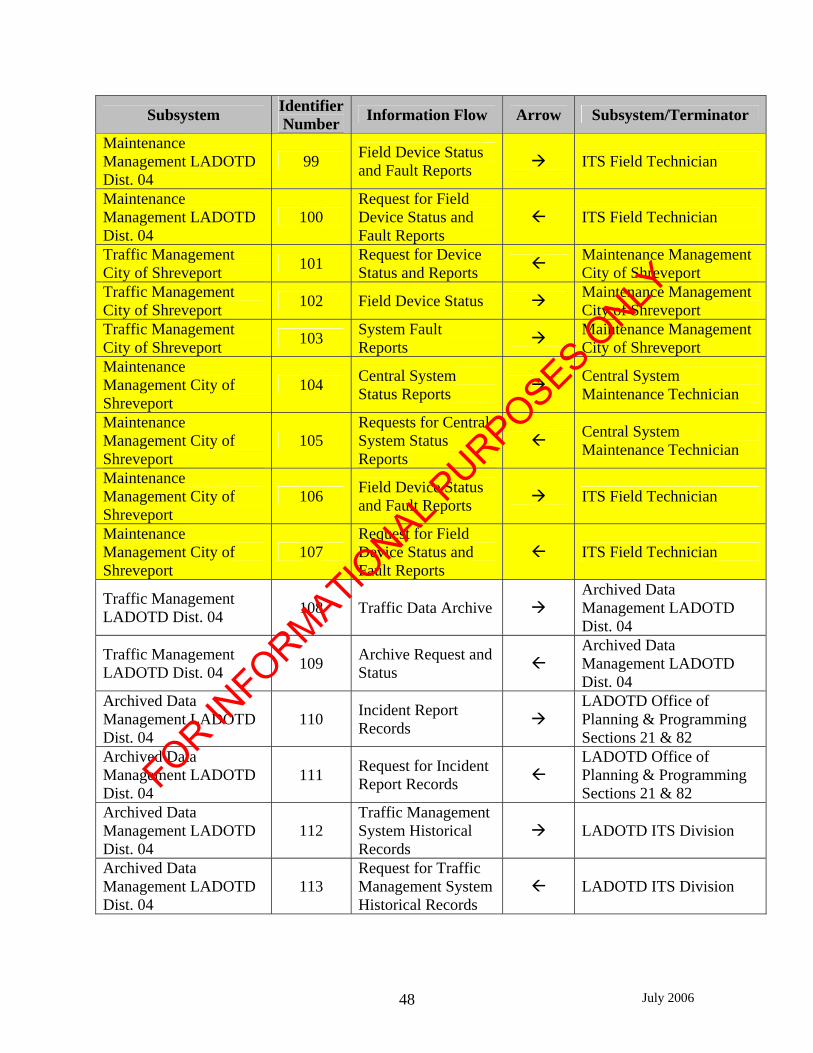
July 2006 48
Subsystem IdentifierNumber Information Flow Arrow Subsystem/Terminator
Maintenance Management LADOTD Dist. 04
99 Field Device Status and Fault Reports ITS Field Technician
Maintenance Management LADOTD Dist. 04
100 Request for Field Device Status and Fault Reports
ITS Field Technician
Traffic Management City of Shreveport 101 Request for Device
Status and Reports Maintenance Management City of Shreveport
Traffic Management City of Shreveport 102 Field Device Status Maintenance Management
City of Shreveport Traffic Management City of Shreveport 103 System Fault
Reports Maintenance Management City of Shreveport
Maintenance Management City of Shreveport
104 Central System Status Reports Central System
Maintenance Technician
Maintenance Management City of Shreveport
105 Requests for Central System Status Reports
Central System Maintenance Technician
Maintenance Management City of Shreveport
106 Field Device Status and Fault Reports ITS Field Technician
Maintenance Management City of Shreveport
107 Request for Field Device Status and Fault Reports
ITS Field Technician
Traffic Management LADOTD Dist. 04 108 Traffic Data Archive
Archived Data Management LADOTD Dist. 04
Traffic Management LADOTD Dist. 04 109 Archive Request and
Status Archived Data Management LADOTD Dist. 04
Archived Data Management LADOTD Dist. 04
110 Incident Report Records
LADOTD Office of Planning & Programming Sections 21 & 82
Archived Data Management LADOTD Dist. 04
111 Request for Incident Report Records
LADOTD Office of Planning & Programming Sections 21 & 82
Archived Data Management LADOTD Dist. 04
112 Traffic Management System Historical Records
LADOTD ITS Division
Archived Data Management LADOTD Dist. 04
113 Request for Traffic Management System Historical Records
LADOTD ITS Division
FOR INFORMATIO
NAL PURPOSES O
NLY

July 2006 49
Subsystem IdentifierNumber Information Flow Arrow Subsystem/Terminator
Archived Data Management LADOTD Dist. 04
114 Traffic Management System Historical Records
LADOTD District 04 Operations
Archived Data Management LADOTD Dist. 04
115 Request for Traffic Management System Historical Records
LADOTD District 04 Operations
Maintenance Management LADOTD Dist. 04
116 Archive Request and Archive Status
Archived Data Management LADOTD Dist. 04
Maintenance Management LADOTD Dist. 04
117 Maintenance Data Records
Archived Data Management LADOTD Dist. 04
Traffic Management City of Shreveport 118 Traffic Data Archive
Archived Data Management City of Shreveport
Traffic Management City of Shreveport 119 Archive Request and
Status Archived Data Management City of Shreveport
Archived Data Management City of Shreveport
120 Traffic Management System Historical Records
City of Shreveport Traffic Engineering
Archived Data Management City of Shreveport
121 Request for Traffic Management System Historical Records
City of Shreveport Traffic Engineering
Archived Data Management City of Shreveport
122 Traffic Management System Historical Records
City of Shreveport Planning & Programming
Archived Data Management City of Shreveport
123 Request for Traffic Management System Historical Records
City of Shreveport Planning & Programming
Maintenance Management City of Shreveport
124 Archive Request and Archive Status
Archived Data Management City of Shreveport
Maintenance Management City of Shreveport
125 Maintenance Data Records
Archived Data Management City of Shreveport
Traffic Management LADOTD Dist. 04 126 Traffic Information Information Service
Provider Traffic Management LADOTD Dist. 04 127 Request for Traffic
Information Information Service Provider
Information Service Provider 128 Traffic Information
Status ISP Operator
Information Service Provider 129 Traffic Information
Requests ISP Operator
FOR INFORMATIO
NAL PURPOSES O
NLY
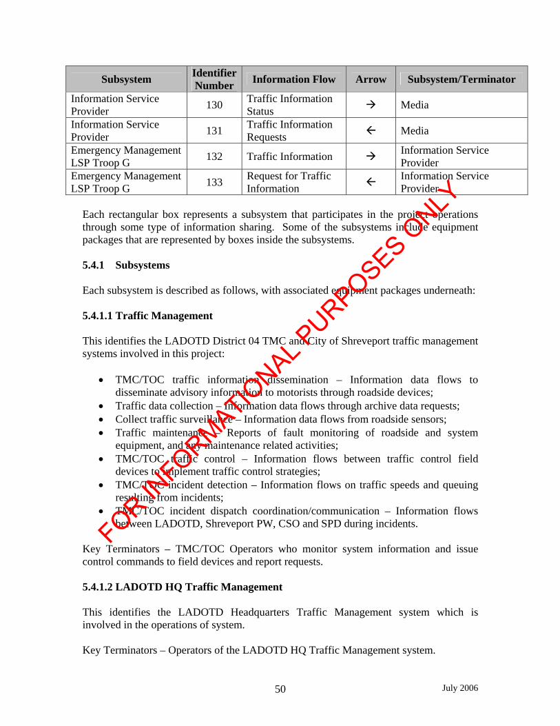
July 2006 50
Subsystem IdentifierNumber Information Flow Arrow Subsystem/Terminator
Information Service Provider 130 Traffic Information
Status Media
Information Service Provider 131 Traffic Information
Requests Media
Emergency Management LSP Troop G 132 Traffic Information Information Service
Provider Emergency Management LSP Troop G 133 Request for Traffic
Information Information Service Provider
Each rectangular box represents a subsystem that participates in the project operations through some type of information sharing. Some of the subsystems include equipment packages that are represented by boxes inside the subsystems. 5.4.1 Subsystems Each subsystem is described as follows, with associated equipment packages underneath: 5.4.1.1 Traffic Management This identifies the LADOTD District 04 TMC and City of Shreveport traffic management systems involved in this project:
• TMC/TOC traffic information dissemination – Information data flows to disseminate advisory information to motorists through roadside devices;
• Traffic data collection – Information data flows through archive data requests; • Collect traffic surveillance – Information data flows from roadside sensors; • Traffic maintenance – Reports of fault monitoring of roadside and system
equipment, and any maintenance related activities; • TMC/TOC traffic control – Information flows between traffic control field
devices to implement traffic control strategies; • TMC/TOC incident detection – Information flows on traffic speeds and queuing
resulting from incidents; • TMC/TOC incident dispatch coordination/communication – Information flows
between LADOTD, Shreveport PW, CSO and SPD during incidents.
Key Terminators – TMC/TOC Operators who monitor system information and issue control commands to field devices and report requests.
5.4.1.2 LADOTD HQ Traffic Management This identifies the LADOTD Headquarters Traffic Management system which is involved in the operations of system. Key Terminators – Operators of the LADOTD HQ Traffic Management system.
FOR INFORMATIO
NAL PURPOSES O
NLY
July 2006 51
5.4.1.3 Other Traffic Management This identifies the other local and LADOTD District TMC’s traffic management systems which are involved with sharing traffic and incident information. Key Terminators – Operators of other local and LADOTD District Traffic Management Systems.
5.4.1.4 Roadway This identifies the physical highway environment for both the LADOTD District 04 and City of Shreveport.
• Roadway traffic info dissemination – devices that disseminate traffic info to drivers;
• Roadway basic surveillance – devices that collect real time traffic flow information;
• Roadway signal control – devices that regulate right-of-way at signalized intersections.
Key Terminators – Field Devices which are interconnected to Traffic Management System (i.e., DMS, Vehicle Detectors, CCTV, and Traffic Signals).
5.4.1.5 Maintenance Management This identifies the LADOTD District 04 and City of Shreveport maintenance management system for the ITS central and field components. The City of Shreveport maintenance of ITS equipment is limited to traffic signal controllers. LADOTD District 04 maintenance management system is the local provider of maintenance information to the LADOTD ITS Maintenance Section at LADOTD Headquarters that coordinates ITS maintenance activities.
• Maintenance data collection – monitors the operational status of field equipment and detects and reports failures;
• ITS field maintenance – tracks the repair or replacement of the failed field equipment;
• Central system maintenance - tracks the repair or replacement of the failed central system equipment.
Key Terminators – Field and Central System Maintenance Technicians (for LADOTD, this is the Telecommunications Technician; for the City of Shreveport, this is the City Traffic Engineer or designee) who respond to report failures.
FOR INFORMATIO
NAL PURPOSES O
NLY

July 2006 52
5.4.1.6 Emergency Management This identifies the LSP Troop G, Caddo Parish Communications District, SPD and CSO emergency management systems involved in this project.
• Emergency response management – systems used to receive incident information, locate field personnel units, dispatch and communicate with emergency responders.
Key Terminators – Police Dispatchers who receive and send information with other partner agencies and Field Troopers.
5.4.1.7 Other Emergency Management This identifies the other Local Agency Dispatch Centers and any other agency emergency management systems. Key Terminators – Other Local Agency Emergency Management Dispatchers.
5.4.1.8 Emergency Management Vehicle Vehicle systems used by Police field personnel.
• On board emergency vehicle incident management communication – equipment to communicate with Police dispatch center.
Key Terminators – Police Field Officers, Deputies, Troopers who communicate to Dispatchers and other partnering agencies. 5.4.1.8 Information Service Provider Information Service Providers including the LADOTD, that collects traffic information, processes the data, and broadcast traveler information over various forms of media.
• 511 system – system that is providing traveler information via telephone and other forms of media throughout Louisiana
Key Terminators – Information Service Providers (ISP) and Media who collect traveler-related information from the Traffic Management Systems and disseminate to the traveling public through various mediums.
5.4.1.10 Archived Data Management This is the system that archives data from traffic and emergency management systems.
FOR INFORMATIO
NAL PURPOSES O
NLY

July 2006 53
• ITS data repository – system that collects and stores traffic and emergency related information; and
• Traffic and roadside data archival – System that processes collected data and provides information upon requests.
Key Terminators – LADOTD and City of Shreveport Units that can make use of data collected from the Traffic Management System. 5.5 Stakeholder Requirements The following list each system component and the corresponding system interfaces with a concise description of the high-level functional requirements for the LADOTD and City of Shreveport region needs. Note that not all of these system components will be deployed in this specific project, but rather, are to be deployed in other ongoing or future projects within the region. See Section 5.6 herein in regards to the system components to be deployed per this project. 5.5.1 Motorist Advisory Elements Elements must be able to provide pertinent advisory and route guidance information to motorists about incidents. Motorists must be able to receive information that can be understood in advance of exit locations which use this project corridor as a planned alternate route in order for motorists to react in a safe manner, yet not too far from these exit points so that information may be retained. Dissemination elements must be permanently situated and dynamic in nature to accommodate traffic incidents in various locations and adjustments to traffic control plans. The motorist advisory elements must be integrated with the TMC/TOC central system. District 04 TMC operators should be able to receive operating status of the elements, and ability to provide pre-programmed and customized information through the elements. City of Shreveport TOC operators should be able to receive operating status of the elements (e.g., message currently posted on DMS). The elements must also be programmable from laptop computers used by LADOTD technicians. The elements must be easily maintainable by available resources of the LADOTD. 5.5.2 Traffic Signal Control These elements allow TMC/TOC operators to monitor traffic signal operations, and ability to adjust signal timing operations to accommodate traffic incident response plans along the alternate routes. The traffic signal control must be integrated with the TMC/TOC central system. TMC/TOC operators should be able to receive operating status of the elements and be
FOR INFORMATIO
NAL PURPOSES O
NLY

July 2006 54
able to provide pre-programmed and customized signal timings through the elements. The elements must be easily maintainable by available responsible agency resources. 5.5.3 Traffic Flow Verification These elements shall collect real-time traffic flow information deployed in a manner that TMC/TOC operators can monitor and verify traffic flow conditions during a traffic incident throughout the project corridor, supplementing video surveillance. Data from these elements can support traffic incident verification applications, and be used to monitor conditions for potential queuing during traffic incidents (i.e. the use of thresholds based on certain drops in vehicle speeds). The traffic flow verification elements must be integrated with the respective TMC/TOC central system. TMC/TOC operators should be able to receive operating status of the elements and be able to quantify real-time traffic conditions through the elements. These systems shall support vehicle counting and data archiving of historical data along the entire project limits. The elements must be easily maintainable by available responsible agency resources. 5.5.4 Video Surveillance Video surveillance is to be used for traffic incident verification and assessment of traffic incident type and duration. Video coverage from each camera shall cover identified “hot spots” along LA 526 and 100% of elevated portions of I-49/LA 526, I-49/LA 3132 interchanges and future LA 3132/LA 526 interchange. Real-time color video transmission with remote pan/tilt/zoom capabilities is required. Located at potential bottleneck locations (i.e. interchanges, intersections), these elements support traffic incident verification needs. The video surveillance elements in the project limits must be integrated with the TMC/TOC central system. District 04 TMC operators should be able to receive real-time video of the elements, and ability to control the camera pan/tilt/zoom. The District 04 TMC will have primary pan/tilt/zoom control. Access to video shall be provided to the approved local agencies (including City of Shreveport TOC) if requested. No video is to be recorded or archived. The elements must be easily maintainable by available resources of the LADOTD and/or responsible local agency. The locations identified as part of this project requiring full motion video surveillance (i.e, pan-tilt-zoom, PTZ) are as follows:
• I-49/LA 3132 interchange • I-49/LA 526 interchange • LA 3132/LA 526 interchange (currently under construction) • LA 526/Walker Rd. intersection • LA 526/Mansfield Rd. intersection
FOR INFORMATIO
NAL PURPOSES O
NLY

July 2006 55
• LA 526/Kingston Rd. intersection • LA 526/Linwood Ave. intersection • LA 526/LA 1 intersection • LA 1/LA 511 intersection
5.5.5 LADOTD District 04 TMC Central System Provides monitor and control capabilities to District 04 TMC operators of all integrated field elements and permits information sharing with other centers including but not limited to City of Shreveport TOC, LADOTD HQ TMC, and other District TMC’s. An operator friendly interface with a Geographical User Interface (GUI) map to relate all field elements is required to perform all functions. The central system element must be integrated with all project field elements. TMC operators should be able to receive operating status of the elements and be able to provide pre-programmed and customized information through the elements. The central system must be easily maintainable by available resources of the LADOTD. The District 04 TMC Central System shall be integrated to the proposed Louisiana Advanced Transportation System (LaTIS) network with the ability to transmit and exchange video and data with other District TMC’s and LSP centers on the network. 5.5.6 LADOTD Maintenance Management System Presents field equipment status to Maintenance and Central System Personnel and reports failures to each. It also tracks the repair or replacement of the failed equipment. 5.5.7 Data Archival Systems A data archival system shall be integrated with the TMC/TOC Central System. The data archival system shall be capable of storing traffic counts, speeds and other historical data. The data archival system shall be capable of storing information such as raw data files and processed data in summarized information form based on programmable interval times (i.e. 5 minutes, 15 minutes, hourly, daily). Data format shall meet the needs of planning and safety stakeholders from the LADOTD and City of Shreveport. Additionally, the data archival system shall store maintenance and operations data. Maintenance includes service records noting work performed with time stamps. Operations data includes operations control changes through the central system or via portable laptops integrated with the system, packaged in a log format noting dates and times of operations activities. Data shall be stored for up to 21 days, with ability to backup the information on separate disks.
FOR INFORMATIO
NAL PURPOSES O
NLY

July 2006 56
5.5.8 Caddo Communications District / SPD Dispatch / CSO Dispatch / LSP Dispatch City Police Dispatch and Caddo Sheriff Dispatch shall receive real-time traffic control information from District 04 TMC and City TOC as it is available when requested by a phone call which includes traffic flow, information messages being disseminated, and video. They shall not have control of traffic signals, DMS or pan/tilt/zoom control of CCTV. The system elements provided to the LSP, CSO, and SPD must be easily maintainable by available resources of the LADOTD, LSP and/or City. 5.6 Project Functional Requirements Using the Project Architecture, the Concept of Operations, and the stakeholder requirements, this section details the high-level Functional Requirements for this project. During the detailed design phase, these functional requirements will serve as the basis for the detailed requirements and specifications that will be part of the procurement package for implementation. The Functional Requirements are presented below: 5.6.1 The LADOTD traffic management systems for the Shreveport/Bossier City region
shall be deployed in the interim at the District 04 TMC until a permanent TMC is constructed in the future near the I-49/I-20 interchange.
5.6.1.1 The traffic management system shall receive and process data from traffic sensors
and provide an interface for transfer of data to the District 04 TMC. 5.6.1.2 The traffic management system shall receive video images and allow selective
distribution and user control of full motion video images to the District 04 TMC. 5.6.1.3 The traffic management system shall control City of Shreveport TOC ability to
use PTZ of the CCTV. 5.6.1.4 Devices deployed on the roadway (signal controllers, sensors, dynamic message
signs, and CCTV) shall interface with the traffic management system to provide traffic data, device status, and device control.
5.6.1.5 The traffic management system shall calculate travel times through sensor data
and automatically display travel time messages on dynamic message signs. 5.6.1.6 The traffic management systems shall interface with traffic control signals along
state routes for changing time of day plans, preemptions, and coordination.
FOR INFORMATIO
NAL PURPOSES O
NLY

July 2006 57
5.6.1.7 The traffic management system shall have back-up redundancy to allow complete control and access to all traffic management system functions, data, CCTV images, and device control.
5.6.1.8 The traffic management system shall provide an interface for users to optimize the
traffic control strategy based on near-real time information. 5.6.1.9 The traffic management system shall support incident response coordination with
the emergency management systems and be capable of implementing traffic control strategies in response to incidents.
5.6.1.10 All traffic and emergency management systems shall provide an interface
to allow the collection and warehousing/storage of ITS data. 5.6.1.11 The maintenance management systems shall collect real-time equipment
information regarding the operational status and will track and report failures. Equipment status reports shall log all failures.
5.6.1.12 The traffic management system shall be able to be expanded for future
interfaces including sharing of equipment collected data, equipment status, equipment control, and video transfer with other centers deemed appropriate, information service providers, and data archives.
5.6.2 The City of Shreveport traffic management systems shall be deployed at the City
TOC in the interim or identified location to house the system. 5.6.2.1 The traffic management system shall receive and process data from traffic sensors
and provide an interface for transfer of data to the City of Shreveport TOC. 5.6.2.2 The traffic management system shall allow selective distribution of full motion
video images to the City of Shreveport TOC. 5.6.2.3 Devices deployed on the roadway (sensors, dynamic message signs, and CCTV)
shall interface with the traffic management system to provide traffic data and device status.
5.6.2.4 The traffic management systems shall interface with traffic control signals along
state routes under the city - state maintenance agreement for changing time of day plans, preemptions, and coordination.
5.6.2.5 The traffic management system shall provide an interface for users to optimize the
traffic control strategy based on near-real time information. 5.6.2.6 The traffic management system shall support incident response coordination with
the emergency management systems and be capable of implementing traffic control strategies in response to incidents.
FOR INFORMATIO
NAL PURPOSES O
NLY

July 2006 58
5.6.2.7 All traffic and emergency management systems shall provide an interface to allow
the collection and warehousing/storage of ITS data. 5.6.2.8 The maintenance management systems shall collect real-time equipment
information regarding the operational status and shall track and report failures. Equipment status reports shall log all failures.
5.6.2.9 The traffic management system shall be able to be expanded for future interfaces
including sharing of equipment collected data, equipment status, equipment control, and video transfer with other centers deemed appropriate, information service providers, and data archives.
Chapter 6.0 Alternative System Configurations Analysis
This stage of the Systems Engineering process evaluates different ways to build the system and a framework to compare the alternatives. By evaluating a set of “system design trade-offs”, an analysis will be used in determining which one gives us the best chance of successfully building the most desirable system. This will be done by assessing three factors: technical, cost, and schedule feasibility. Alternative configurations identify not only components relative to the project deployment but the regional system configuration as well. However, items per the regional configuration are identified as requiring further investigation outside the scope of this project and do not necessarily assess the technical, cost, and schedule feasibility. The following sections provide background of the alternatives for consideration. 6.1 Component Technologies Based upon the system requirements identified in Chapter 5, configuration alternatives are presented below for various system components. 6.1.1 Traffic Signal Control The regional alternative configurations to consider with regards to Traffic Signal Control elements are: • ITS equipment and signal controllers operate under one control software; • All signals integrated into one signal system, not integrated with ITS equipment
elements; and • City and LADOTD to operate separate signal systems.
The Shreveport/Bossier City region is operating ITS equipment and traffic signal controllers via separate software packages. Traffic signals, both city and state, are operating via Naztec’s Streetwise software whereas the ITS equipment (RVD’s, CCTV’s, and DMS) are operating via 360 Surveillance’s ITS Cameleon v4 software.
FOR INFORMATIO
NAL PURPOSES O
NLY
July 2006 59
The desire for having one software package for both ITS equipment and signal controllers has not been addressed by the stakeholders in the region. The existing configuration of having two software packages is consistent with other regions throughout the state. A single software package benefits operations because it allows for direct configuration between signals and ITS equipment whereas separate software does not. For example, alarms can be set to prompt the operator to adjust signal timing for signal on the alternate route when detection on the interstate identifies a traffic incident. Unless the desire is addressed for this regional change, the project components of this project will integrate into two legacy software packages, one for the signals and the second for ITS equipment. If desired, investigation for a single software should be provided outside this project scope. Associated cost would include integration of the legacy systems and development/procurement of the single software package. Consideration of this option is not feasible per this project. The operational jurisdiction of the intersections within the project limits have been set, as described in Chapter 2. If this form is followed for deployment, the city intersections would see the intersection controllers integrated with the city’s legacy system (this includes the state signals under the maintenance agreement) and the State intersections integrated with the State’s system. It is planned that each agency will operate their own signals on their systems. Each agency has staff resources identified to be able to operate and manage the system as needed during traffic incidents. 6.1.2 Traffic Flow Measurement The alternative configurations to consider with regards to Traffic Flow Measurement elements are: • Use of signal system detectors; and • Separate detectors from the signal system.
Radar detection is currently used by the LADOTD on freeways with successful experience. It requires support structures for deployment. On the arterials, detection is primarily used to serve as input for actuated operations of the traffic signal controllers, and the detectors are directly connected to the controllers. Currently, video imaging detection is planned to be implemented at the signalized intersections on this project. Video imaging detection has been highly successfully throughout the state for intersection detection. Since it will be highly desirable to have real-time traffic flow measurements of the arterial during incidents for traffic management response strategies, the ability of the traffic signal detection to provide this information must be adequate. Cost associated with using the detection provided at the signalized intersections is minimum since communications with the signal controller is being provided as part of this project. The cost would include only the integration of the detection into the ITS
FOR INFORMATIO
NAL PURPOSES O
NLY

July 2006 60
equipment software. Cost for integrating the video imaging detection equipment is approximately $800 per intersection whereas the cost for installing additional radar detection solely for traffic incident management is approximately $10,000 each with utilization of existing structures. 6.1.3 Video Surveillance The alternative configurations to consider in regards to Video Surveillance elements are: • Integrated with city traffic management systems only; • Integrated with state traffic management systems only; • Integrated with city and state traffic management systems.
It is desired that CCTV cameras to be installed at key intersection locations on LA 526 per this project. There is mutual desire to share video and camera control between both the City and State agencies under an agreeable operational protocol. The key issue is the integration configuration of video images to the various centers. Existing CCTV cameras in the region are being operated using 360 Cameleon ITS v4 at both the City of Shreveport TOC (view only) and District 04 TMC. The cost associated with integrating the additional CCTV cameras from this project to either of these centers is minimal. However, if additional centers are to be provided with video images and are not currently on the LaTIS network, cost will have to be evaluated based on level of operability, resolution of images, and image rate desired for each center. This regional investigation would be required outside the scope of this project. It is highly feasible to provide local and state law enforcement agencies with the ability to view live video images for traffic incident management and emergency management. 6.1.4 Traffic Management Systems The alternative configurations to consider with regards to Traffic Management Systems are: • Legacy versus new system; • Separate component management systems; • Integrated traffic management systems; and • Integration amongst other stakeholders.
Generally it is easier for an agency to maintain, or upgrade if necessary, their legacy system when adding new field elements. This is done to minimize risks and maintain familiarity amongst personnel; however, this may prohibit abilities to share information and provide a back-up option when an agency’s system malfunctions. Installation of a new system provides a means to better share information and coordinate activities; however, the added functionality will add to the project costs. The ability to integrate systems between LADOTD and the City and with LSP and local police is strongly
FOR INFORMATIO
NAL PURPOSES O
NLY

July 2006 61
recommended for efficient incident management operations but should be done in a thrifty manner. Providing the capability for other stakeholders to access system functions through internet protocols on their own personal workstations is expected to present the most cost efficient integration. This project is one of the multiple phased ITS equipment deployments for the region. Cost for integrating new ITS equipment into the system is minimal compared to that of purchasing a new system. It is the intent of the scope for this project to integrate with the legacy system based on both associated cost and feasibility. If further investigation is required for a new system, it will be conducted outside the scope of this project. 6.1.5 Archived Data Management Systems The alternative configurations to consider with regards to Archived Data Management System elements are: • Integrated within traffic management and emergency management systems; and • Separate systems with information flows to traffic and emergency management
systems. The ability to archive data presents agencies with ability to measure system benefits and track the performance of various activities. This capability is strongly recommended for inclusion in the project. However, archived data management systems can be very complex with high costs and potential long schedules for delivery since they are not common to the ITS practice at this time. While a separate data management system that can serve traffic and emergency management systems, as well as other regional ITS deployed systems, are ultimately a goal, this option would seem to be prohibitive in cost, and not affordable for this effort. Therefore, at a minimum, archived data management features should be included in any traffic and emergency management system deployed for this project, including data logging and storage capabilities. 6.2 Communications Technologies For each system interface identified in Chapter 5 and the component technology identified in the previous section, communications technology alternatives are compared in a matrix for each interface. 6.2.1 Center-to-Field Interfaces The technology options will depend upon the location and the specific transmission requirements of the field elements. Video surveillance will require far larger bandwidth than the data transmissions required for all other elements. Fiber wireline technology will be most practical for elements on the interstate routes, as the interstate has a controlled environment with many possible elements, including video cameras. Elements
FOR INFORMATIO
NAL PURPOSES O
NLY

July 2006 62
on arterial highway segments, dedicated alternate routes, may find the other alternatives more practical and each should be individually analyzed. Capital costs associated with Fiber wireline is greater than that of wireless. The general rule of thumb for determining fiber wireline cost is $50/foot installed. Wireless cost depends on the topography, available frequencies, available towers/structures, bandwidth requirements and number of devices to be installed. Wireless tends to have higher operational costs, and may not be reliable on a 24 hour–a-day basis. Since the Shreveport/Bossier City has deployed fiber wireline at the extents of the project limits and this project requires deployment of video cameras, it is feasible and recommended to install fiber wireline to create a loop for redundancy and accommodate required bandwidth. 6.2.2 Center-to-Center Interfaces The scope of this project includes the interface between the LADOTD District 04 and the City of Shreveport TOC traffic management system. At a regional level, operations of this system includes interfaces with the LSP Troop G, local police dispatch centers, and possibly remote centers (i.e. LADOTD HQ TMC and adjacent LADOTD Districts). Center-to-center interface exist between District 04 and City of Shreveport TOC via a fiber wireline as part of the LaTIS network. Use of existing communications or the proposed LaTIS is the most practical alternative for center-to-center for other agencies in the region or remote centers, as this has been analyzed in the Statewide ITS Plan. The scope of services for this project does not include providing center-to-center with regional or remote agencies; however, this is highly desired and recommended. Comparative analysis and implementation for these interfaces should be considered priority for the region. 6.2.3 Field Responder to Center Interfaces Verbal communication capability is critical for LADOTD and city field resources to communicate with their respective TMC/TOCs. Caddo Parish Communication District provides 800 MHz radio for the parish agencies and allows all agencies within the region to interface with the system via workgroup configuration. Also, Caddo Parish Communication District is currently investigating making available a mobile data interface for field responders; however, access will be restricted and prioritized due to bandwidth availability. Cost associated with interfacing with the existing system is the cost of the field responder units. LADOTD and city field personnel should be equipped with remote access to their traffic management system in order to monitor real time conditions and be able to display messages on DMS in the event the TMC/TOC is not staffed, or has lost communications with the field elements.
FOR INFORMATIO
NAL PURPOSES O
NLY

July 2006 63
LADOTD and LSP are currently not interfaced with this system, and it is recommended to allow for direct interface amongst the agencies. 6.2.4 Field Responder to Field Responder In addition to communications within respective agencies, each emergency responder to an incident should have the compatibility to communicate with each other, presumably through compatible radio systems. The existing Caddo Parish Communications District 800 MHz radio system mentioned above allows for field-to-field communications. The recommendations indicated for the field-to-center also pertains to the field-to-field. 6.3 Summary It is too difficult to draw conclusions on these system configuration options at a regional level since the scope of this project is for field deployment of ITS equipment and traffic signal upgrades. On a project level, design requirements, operations and maintenance have been provided at a level to ensure a complete and functional system. However, this analysis provides a better understanding of the issues that are being faced in the region and some of the desirable outcomes of the ultimate system configuration that will best serve the region’s stakeholders. In general, a traffic management system that is integrated with monitoring and control capabilities of all field components utilizing ITS standards is recommended for the LADOTD District 04. Furthermore, ability for the District to have the capability to monitor and control local agency field elements is strongly recommended to ensure greater coordination and provide a system back-up. During any period when the traffic management system is not being actively monitored, control would revert to the statewide LADOTD HQ TMC in Baton Rouge once remote communications with required bandwidth becomes available. Until this point is established, local on-call operations will be provided for after hours services. Also, recommendation for the future is to expand the system with the LSP Troops ‘G,’ City of Shreveport Police Department and the Caddo Parish Sheriff’s Office at their dispatch center with limited monitoring capabilities. Consideration may be given to allow police departments the ability to display pre-programmed messages under agreeable conditions with the LADOTD during periods when LADOTD personnel cannot immediately perform the display functions when needed to respond to an incident scenario, and ability for pan/tilt/zoom control of CCTV cameras. The LSP and Local Police dispatch centers can be provided with the ability to monitor all field elements, through a local workstation that is remotely integrated with the LADOTD District 04 traffic management system. Due to the strong reliance of the management decisions by field personnel within the LADOTD, SPD, CSO, and LSP as well as local agency emergency responders, integrated
FOR INFORMATIO
NAL PURPOSES O
NLY

July 2006 64
communications devices are recommended to facilitate the sharing of information and coordination of activities during incident management operations. Chapter 7.0 Procurement Options The implementation of the Shreveport/Bossier City ITS Deployment Immediate Term Phase 2 will include the deployment of numerous ITS technologies. These technologies will be used by LADOTD to monitor traffic operations within the project limits (Figure 2-1), detect and evaluate incidents to determine the need for traffic diversion, and communicate roadway conditions to the motoring public. Once the traffic incident is resolved, the roadway facility can return to its normal operating conditions. This chapter identifies the procurement options for the ITS hardware, software, and communication technologies that may be deployed by LADOTD to satisfy previously identified functional requirements as a part of the Shreveport/Bossier City ITS Deployment Immediate Term Phase 2 project. 7.1 Procurement Options of ITS Technologies Based on review of the Louisiana DOTD procurement regulations, ITS technologies are procured under the Louisiana Administrative Code Title 70: XXIII Chapter 3. Commodities purchased by the DOTD Procurement Section fall into two categories, either non-exempt commodities or exempt commodities. 7.1.1 Non-Exempt Commodities
Non-exempt commodities are defined as materials and supplies that will not become a component part of any road, highway, bridge, or appurtenance thereto. These commodities are subject to the requirements of the Louisiana Procurement Code and such regulations promulgated by the Commissioner of Administration and are governed by the rules and regulations adopted by the Director of State Purchasing.
Purchases of less than $500.00 (or the amount set in the latest Governor's Executive Order, whichever is higher) do not require competitive bids.
All Request for Quotations covering non-exempt commodities that exceed the non-competitive dollar limit but do not exceed $5,000.00 (or the dollar limits listed in the latest Governor's Executive Order, whichever is higher) are awarded on the basis of the lowest responsive price quotation solicited from at least three bona fide, qualified bidders. All Request for Quotations covering non-exempt commodities having an estimated cost which exceeds $5,000.00 but which do not exceed $20,000.00, (or the dollar limits listed in the latest Governor's Executive Order, whichever is higher) are awarded on the basis of the lowest responsive price quotation solicited from at least five bona fide, qualified bidders.
FOR INFORMATIO
NAL PURPOSES O
NLY

July 2006 65
Purchases of non-exempt commodities having an estimated cost which exceeds $20,000.00 (or the latest delegated purchasing authority, whichever is higher) are prepared and forwarded to the Office of State Purchasing for bid solicitation.
7.1.2 Exempt Commodities Exempt commodities are defined in R.S.39:1572 as materials and supplies that will become a component part of any road, highway, bridge, or appurtenance as defined in R.S. 39:1572.
Purchases of exempt commodities having an estimated cost which exceeds the non-competitive dollar limit of $500 (or the amount set in the latest Governor's Executive Order, whichever is higher) but which do not exceed $25,000.00 (or the latest revision to R.S. 48:205, whichever is higher) are also referred to as Request for Quotations.
All Request for Quotations covering exempt commodities which exceed the non-competitive dollar limit but which do not exceed $5,000.00 (or the dollar limits listed in the latest Governor's Executive Order, whichever is higher) are awarded on the basis of the lowest responsive price quotation from at least three bona fide, qualified bidders.
All Request for Quotations covering exempt commodities having an estimated cost which exceeds $5,000.00 (or the dollar limit listed in the latest Governor's Executive Order, whichever is higher) but which do not exceed $25,000.00 (or the latest revision to R.S. 48:205, whichever is higher) are awarded on the basis of the lowest responsive price quotation solicited from at least five bona fide, qualified bidders. .
Purchase of exempt commodities having an estimated cost which exceeds $25,000.00 (or the latest revision to R.S. 48:205, whichever is higher) will be processed as Sealed Bids and shall be advertised in accordance with R.S. 48:205.
7.2 ITS Hardware Technologies ITS hardware technologies can be segmented into three categories: traffic monitoring, incident evaluation, and communications with the traveling public. ITS technologies use by transportation agencies for monitoring traffic operations is primarily achieved with remote sensory devices. These devices employ radar, video imaging, and magnetic inductance to “sense” the presence and movement of vehicles traveling along the roadway facility. These devices are located at strategic points and at specific distances along the roadway. They can be non-intrusively mounted on existing light and sign structures (radar and video) or placed inside the roadway service (wire loops). Although the non-intrusive technologies are generally preferred due to operational considerations, there are a very limited number of experienced vendors of these products and the products are continually improving through frequent revised model versions.
FOR INFORMATIO
NAL PURPOSES O
NLY

July 2006 66
CCTV technologies are primarily used for incident evaluation and traffic monitoring. This technology, supported with voice communication, allows traffic and law enforcement agencies to effectively evaluate a traffic incident, assigning the appropriate resources to address the situation. This technology allows traffic management personnel to visually observe traffic operations on a roadway facility and determine how traffic is moving. There are many more product options with CCTV, as there are many other applications than highway transportation. Dynamic message signs (DMS) are an effective way of disseminating real-time traffic conditions to the traveling public. A DMS is an electronically controlled message board located at a strategic location near or over the travel lanes of the roadway. For freeway operations the typical DMS has three (3) lines of fifteen (15) eighteen (18) inch characters capable of displaying a word message that can be read by motorists. This message can be predetermined or an operator can create and display (thus the term dynamic) a new a message to fit any situation. The DMS industry has achieved great successes in standardizing products to meet NTCIP standards; however, just a few select vendor products are available. 7.3 Software All of these ITS technology system components typically come with software as part of the hardware purchase. This software allows operators to control and manage the hardware components located along the roadway. Typically these component systems can be integrated with existing traffic management system operating software. This integration is usually performed by in-house software technicians or by the vendor from whom the system integration software was purchased. Since the component software is considered a component of the hardware system, it would be typically purchased as an exempt commodity. However, the system integration software could be considered a non-exempt commodity since it is not part of the roadway. It is recognized that the LADOTD will be seeking integrated traffic management system software as a part of a change order to the implementation of Shreveport/Bossier City ITS Near Term Phase 1. At the time of this writing, it is understood that integration software purchased for this project is a product developed and distributed by the 360 Surveillance Company. The implementation of this software for Shreveport/Bossier City ITS Near Term Phase 1 will have a direct bearing on the integration software specified for the Shreveport/Bossier City ITS Deployment Immediate Term Phase 2. 7.4 Communications The communications network (or plant) used to integrate the ITS technology hardware, manage data flows and receive video images is comprised of land-lines (fiber optic, cable, and twisted wire pairs), spread spectrum radio, and microwave or wireless technology. The communications plant connects the TOC to the various ITS components
FOR INFORMATIO
NAL PURPOSES O
NLY

July 2006 67
located along the roadway facility. This allows operators to receive information from the field and display it numerically, graphically, and visually. The information can be used by operators to determine roadway congestion, vehicle travel speeds, lane capacity, and to evaluate incidents. Additionally, operators can use the communication network to send information and communicate with motorists about driving conditions, lane closures and roadway detours. The communication network, built as a component of the ITS network for traffic management is typically purchased as an exempt commodity. The physical communication plant is placed in conduits and equipment cabinets in the roadway right-of-way. However this may not be the case for microwave towers and equipment that are constructed outside of roadway right-of-way, but on other LADOTD properties. Another method used by LADOTD to procure communications is that of leasing communications services from private communications companies. The procurement of communication services would be done in the same manner as the purchase of telephone services for LADOTD. Prices for these services are typically negotiated on a per connection per month basis. 7.5 Project Procurement Methods Available for Use by LADOTD The procurement of ITS technologies and services associated with this project can be acquired by LADOTD using one of or a combination of four different procurement methods. They are:
• Sealed Bid (or Design-Bid-Build) – LADOTD prepares a detailed project design and advertises for interested parties to submit a sealed bid to build the project. The lowest bidder offering a fixed price (all else being equal) is awarded the project. Any changes to the project made by LADOTD that result in additional work is subject to a negotiated change order.
• Design–Build – LADOTD advertises a Notice of Intent and short list teams
(maximum of 5) based on their interest and qualifications. LADOTD prepares a Scope of Services Package which includes a functional specification for the short listed teams to submit proposals for the detail design and implementation of the project. The team with the lowest calculated adjusted score based on their bid price plus time value divided by the technical score is awarded the project. Time value may are may not be considered in the project. Any changes to the project made by LADOTD that result in additional work is subject to a negotiated change order.
• Request for Quotation – This is used primarily in the procurement of different
types of ITS hardware. The LADOTD prepares a specification and solicits bids form three or five bona fide bidders (depending on the purchase amount). The bidder with the lowest price (all else being equal) is the successful bidder.
FOR INFORMATIO
NAL PURPOSES O
NLY

July 2006 68
• Lease – Leasing is used by LADOTD for ITS projects primarily to secure communication services such as a dedicated telephone line to monitor and control a traffic signal. Where there is only one provider, sole sourcing is used.
The selection of a contracting method(s) for use in this project is influenced by a number of factors including: legal and administrative constraints, quality control, liability and responsibility of the contractor, procurement schedule, familiarity of the LADOTD project manager, and past experience. An evaluation of the positive and negative attributes for each method previously identified provides a basis for determining which method(s) should be used for this project. 7.5.1 Sealed Bid Sealed Bid also known as Design-Bid-Build is used primarily in the procurement and construction of ITS projects. Detailed specifications and plans are developed by LADOTD (or their consultant). Individual components of the project are listed as a separate bid item. These specifications and plans are included in a bidder’s package that is advertised for a specific number of days. Individual contractors shall prepare their best price for the project (per bid item) as it is described in the bid package and submit a sealed bid to LADOTD. On a predetermine date all bids are opened and the lowest bidder (this assumes all requirements have been met by the contractor) wins the project. The strengths of this type of procurement are numerous. Sealed bid contracting has been used extensively by the LADOTD for large construction projects. This method is considered the most competitive process to ensure that the project will be procured at the lowest possible cost. The responsibility for procuring components, construction, and installation is the responsibility of the contractor, providing a clear differentiation between the contractor’s responsibility and that of LADOTD. This method of procurement is well understood by senior LADOTD construction engineers and contractors and has been refined over many years of use. Because each item of the project is broken out separately in the bid package, LADOTD project engineers can evaluate how the contractor estimated each component of the project. This can provide insight as to how a contractor intends to build the project and alert LADOTD to possible areas of difficulty the contractor may have. Additionally, competitors who were unsuccessful can examine the successful bid to determine the competitive advantage of the successful bidder. This information theoretically helps improve the bidding efficiency for the next project. The negative associated with this method of procurement is two fold. The first is that the best qualified (i.e. on-time performance, dedication to quality, cooperation with the LADOTD engineers, etc.) contractor has no guarantee of winning the job. A contractor with minimum skills and experience will be awarded the project if they offer the lowest bid. Secondly, this method encourages the contractor to attempt to “re-engineer” the project and to claim additional compensation for work that is outside of the originally bid project. Particularly, this may be the case when the contractor has underestimated project costs to assure they have the lowest bid for award of the project.
FOR INFORMATIO
NAL PURPOSES O
NLY

July 2006 69
7.5.2 Design-Build Design-Build is a method of project development and implementation in which LADOTD executes a single contract with one entity (the design-builder) for design and construction services to provide a finished product. The Department’s role in the project procurement process focuses on describing performance (i.e. functional specification) rather than on how to get that performance. This includes physical components, operational requirements, and performance expectations. The design-builder develops a conceptual design with a project cost. The proposal that fulfills the functional specifications and offers the “best value” to LADOTD based on the technical, time, and price evaluations is awarded the project. Advantages of the design-build procurement include quicker project implementation, reduced contractor claims, possible lower costs, and more innovation. The disadvantage of this type of contracting is the extensive experience curve necessary for LADOTD staff to effectively use this procurement technique. Unfamiliarity with the process increases the opportunity for the project to be insufficiently defined. It is necessary to describe the project in such a way that the design-builder has enough information to deliver the intended project. Additionally, it requires greater technical awareness on the part of evaluators to evaluate and select the “best value” proposal. 7.5.3 Request for Quotations This procurement method can be used to acquire ITS components directly for a supplier. The process requires LADOTD to develop detail specifications for the needed components. State purchasing representatives contact a minimum number of suppliers and ask for quotes based upon equipment specifications. The equipment is then delivered to LADOTD for installation. This installation can be accomplished with in-house staff or contracted labor. The primary advantage of this method is that it allows LADOTD to acquire ITS components more quickly than the sealed bid process. LADOTD purchasing personnel can directly contact a minimum number of suppliers and ask for their best price based on the specification. Once a price is accepted, a purchase order can be issued and the item sent directly to LADOTD. It may also result in components costing less because the purchase is from a supplier directly, eliminating the potential for handling costs being added to the item from a contractor. The negatives associated with this procurement process for the project includes the limitation of how much can be purchased at one time. If ITS components are classified as “exempted” this would limit the purchase amount to $25,000. If the ITS components are classified as “non-exempted” this would limit the purchase amount to $20,000. Additionally, this procurement method increases the administrative involvement of LADOTD and the potential for responsibility conflict if non LADOTD personnel are
FOR INFORMATIO
NAL PURPOSES O
NLY
July 2006 70
employed to install and integrate the components. An example for the above would be LADOTD purchasing a particular ITS component for the project and then selecting a contractor to install the component. The contractor attempts to install the component but fails to get the component to function properly. The contractor may insist that the component provided is defective. This would require LADOTD personnel to become involved in a potential dispute between the contractor and supplier. This could cause considerable slow down in project implementation while the issue is being resolved. 7.5.4 Leasing Where applicable, this procurement method is best suited for the communication component of the project. In situations where ITS components are isolated from LADOTD’s fiber-optic cable trunk-line plant it may be more cost effective to lease communications from a local area provider. This could be in the form of a land-line connection (fiber, coaxial, twisted-wire, etc.) or by wireless connection (license frequency). The advantage of leasing communications services is the reduction in capital costs for ITS equipment located such that LADOTD conventionally provided communication plant is not feasible. The terms of flexibility leasing allow LADOTD to specify the time period and location. The negative to leasing communications services is that service performance and maintainability may not be optimal for ITS and would require LADOTD to sacrifice some system performance for the convenience of accessibility and cost. 7.6 Procurement Method for Project For this project LADOTD should consider two procurement methods. The first is Sealed Bid. LADOTD is anticipated to develop a detailed design and specifications for the project and let for construction. The contractor that offers the most economical price, complying with the all contractual requirements, will be awarded the project. The second procurement method that may be considered is the leasing of communications lines from private communication companies in those locations where leasing is more cost effective than building new communication infrastructure. Currently Southwestern Bell (SBC) and Time Warner Communications would be the primary (and possibly only) entities that may provide leasing services for this project.
FOR INFORMATIO
NAL PURPOSES O
NLY

July 2006 71
Chapter 8.0 Standards Standards are specifications that define how the different ITS sub-components interconnect and interact within the established parameters of the National ITS Architecture. Specifically, they stipulate how the different technologies interoperate to automatically share information. LADOTD benefits from ITS standards for this project in several ways including:
• Reducing the risk of equipment obsolescence; • Reducing the risk of a single point of supply and proprietary products; • Lowering prices for equipment; • Minimizing design and implementation confusion; and • Assuring quality.
Additionally, federal regulations require that ITS projects must conform to the National ITS Architecture and the standards if they are financed using funds from the Highway Trust Fund. The architecture currently identifies 13 key standards areas that can be found in the ITS Standards Requirements Document (SRD). As previously stated in this report, (Chapter 3) standards applicable to the development and deployment of ITS have been identified in the Shreveport/Bossier City Regional ITS Strategic Deployment Plan (Table 3-4). ITS projects that are currently deployed by LADOTD incorporate standards developed by a number of standards developing bodies. The American Association of State Highway and Transportation Officials (AASHTO), Institute of Transportation Engineers (ITE), and National Electrical Manufactures Association (NEMA) have taken the lead in developing standards for traffic management devices and their interoperability. These devices include DMS, traffic signals, traffic sensors, etc. The Institute of Electrical and Electronic Engineers (IEEE) and the International Standards Organization (ISO) primarily provide the standards for communication infrastructure. This includes communication cables, switches, nodes, etc. Finally, the National Electric Code (NEC) provides standards to all related electrical and power requirements associated with ITS projects. It should be noted that the development of standards is an ongoing and evolving process. Therefore standards will need to be continually reviewed as LADOTD implements future projects. The purpose of this chapter is to identify the standards that will be used in developing design concepts, detail design, and operational procedures associated with this project. 8.1 Project Standards The most significant set of standards for ITS projects is the National Transportation Communications for ITS Protocol (NTCIP). This family of standards will establish the parameters for the development, design, and implementation of the ITS component of the
FOR INFORMATIO
NAL PURPOSES O
NLY

July 2006 72
Shreveport/Bossier City ITS Deployment Immediate Term Phase 2. AASHTO, ITE and NEMA have taken the lead in developing NTCIP standards. NTCIP is a family of communication protocols (protocol is a system of rules and procedures governing communications between two devices) and data definition standards that serve and address the diverse needs of the various subsystems and user services presented in the national, state, and regional ITS architectures. NTCIP consists of a whole family of protocols covering the spectrum from point-to-point command/response to sophisticated object oriented techniques. NTCIP provides standards for two different ITS applications: center-to-field (C2F) and center-to-center (C2C), both of which are applicable to this project. 8.1.1 Center-to-Field Standards There are two existing application protocols (and one protocol under development) for C2F communications: the Internet’s Simple Network Management Protocol (SNMP) and the Simple Transportation Management Protocol (STMP). These protocols use the get/set-messaging model. Each protocol has its advantages. SNMP is the simplest to implement. The STMP is the most flexible and band width efficient. Table 8-1 presents the comparison of the two protocols.
Table 8-1: SNMP and STMP Comparisons
Characteristic SNMP STMP
Can send any base date element Yes Yes Bandwidth Efficiency Worse Better (uses dynamic
objects) Supports routing and dial-up Options Options Message Set Supported Limited to 13 Ease of Implementation Easy Hard Devices with either of the two protocols can use the same communications line with other devices using the same protocols. The manufacturer or type of device (traffic signals, DMS, etc.) is not important. Each device is assigned an address that is unique on that line or channel which allows the management system to communicate with that device. The communication link for C2F can be any type of medium; fiber optics, cable, spread spectrum, radio, etc. It does not matter whether the communications medium is owned or leased by LADOTD. The only requirement assumes that communication is a half-duplex poll and response, and the time for transmission and the response time for the end device are within the tolerances the devices need to communicate. Although STMP is designed to use communication channels with slow transmission rates, it is not as bandwidth efficient as proprietary protocols used in the past.
FOR INFORMATIO
NAL PURPOSES O
NLY

July 2006 73
8.2 Standards Applicable to the Project
A number of technical standards must be considered in the development of this project. There are over 80 ITS standards now being developed by different standards development organizations (SDOs). ITS designers are encouraged by United States Department of Transportation (U.S. DOT) to use SDO approved standards when developing ITS projects.
Mapping the applicable ITS standards to the project architecture provides a clearer understanding as to how each standard should be considered in design of the project. There are three architectural components to which the standards must be applied for this project: Center to Field, Center-to-Center and Center-to-Vehicle/Traveler. Adhering to these standards will assure interoperability and interchangeability of the project’s components and its overall integration with current ITS operations. Table 8-2 presents the relevant standards for each architectural component that may be used in the implementation of this project.
Table 8-2: ITS Standards Applicable to Project
Standard Number
Standard Name C2F C2C Center to Veh/Traveler
NTCIP 1101
Simple Transportation Management Framework (STMF)
•
NTCIP 1102
Octet Encoding Rules (OER) •
•
NTCIP 1103
Transportation Management Protocols (TMP)
• •
NTCIP 1104
Center-to-Center Having Convention Specification
•
NTCIP 1201
Global Object Definitions •
NTCIP 1202
Object Definitions for Actuated Traffic Signal Controller
•
NTCIP 1203
Object Definitions for Dynamic Message Signs
•
NTCIP 1205
Object Definitions for CCTV Camera Control
•
NTCIP 1206
Object Definitions for Data Collection and Monitoring (DCM) Devices
•
NTCIP 1208
Object Definitions for CCTV Switching •
NTCIP 1209
Object Definitions for Transportation Sensor Systems (TSS)
•
NTCIP 1210
Field Management Stations - Part 1: Object Definitions for Signal System
•
FOR INFORMATIO
NAL PURPOSES O
NLY

July 2006 74
Standard Number
Standard Name C2F C2C Center to Veh/Traveler
Masters NTCIP 1211
Object Definitions for Signal Control and Prioritization (SCP)
•
NTCIP 1400
TCIP Framework Standard • •
NTCIP 1402
TCIP Incident Management Objects • •
NTCIP 2101
Point to Point Using RS-232 Subnetwork Profile
•
NTCIP 2102
Point to Multi-Point Protocol Using FSK Modem Subnetwork Profile
•
NTCIP 2103
Subnet Profile for Point-to-Point Over RS-232
•
NTCIP 2104
Ethernet Subnetwork Profile •
NTCIP 2202
Internet (TCP/IP and UDP/IP) Transport Profile
• •
NTCIP 2301
Application Profile for Simple Transportation Management Framework (STMF)
•
NTCIP 2302
Application Profile for Trivial File Transfer Protocol
•
NTCIP 2303
Application Profile for File Transfer Protocol
• •
NTCIP 2304
Application Profile for Data Exchange ASN.1 (DATEX-ASN)
•
NTCIP 8003
Profile Frame Work • •
NTCIP 9001
NTCIP Guide • • •
EIA-794 Data Radio Channel (DARC) System • EIA-795 Sub carrier Traffic Information Channel
(STIC) System •
IEEE Std 1404
• •
IEEE Std 1488, 2000
Trail-Use Standard for Message Set Template for ITS
• • •
IEEE Std 1489, 1999
Data Dictionaries for ITS • • •
IEEE Std 1512, 2000
Common Incident Management Sets for Use by Emergency Management Centers
• •
FOR INFORMATIO
NAL PURPOSES O
NLY

July 2006 75
Standard Number
Standard Name C2F C2C Center to Veh/Traveler
IEEE SH 94633-94638
Analysis of Existing Standards and Those Under Development Applicable to the needs of ITS Short Range and Wide Area Wireless Communications
• • •
ITE-AASHTO TM 1.03
Traffic Management Data Dictionary • •
ITE-AASHTO TM 2.01
Message Sets for External Traffic Management Center Communications
• •
ITE 9603-2 Advanced Transportation Controller (ATC) Cabinet
•
ITE ATC Type 270
Advanced Transportation Controller Standard Specification Type 270
•
SAE J1763 General Reference Model • • • SAE J2353 Advance Traveler Information Systems
(ATIS) Data Dictionary • •
SAE J2354 Advanced Traveler Information Systems (ATIS) Message Sets
• •
SAE J2369 ATIS Message Sets Delivered Over Bandwidth Restricted Media
•
Appendix A provides a brief description and application of each standard.
FOR INFORMATIO
NAL PURPOSES O
NLY

July 2006 76
8.3 Testing Achieving system interoperability increases adherence to standardization of concepts. An important step in the adherence to NTCIP standards is to develop the appropriate conformance tests for judging adherence of ITS technologies to the standards. This requires that LADOTD develop and implement testing procedures for the installation, operation, and integration of ITS technologies as it applies to this project. 8.3.1 Unit Testing Unit testing focuses on comparing an implementation against the standards and specified options. This may be performed by inspecting the code to use “proven” software to send test messages to the device. This should be formalized process with the documenting of specific test procedures to be followed. The result of each step of the procedure is to be recorded during the test. Unit testing should simulate field conditions as much as possible. Unit testing provides a basic level of validation and verification that ITS technology or product is conformant to an established standard. The test plan may be designed so that the failure of one procedure provides a clear indication of what problem resides within the implementation. This will minimize the cost of finding and fixing the error or “bug.” A device that passes such a test has a reasonable probability of interoperating and interchanging with others. Manufacturers of ITS equipment typically develop detailed unit testing requirements and procedures for their equipment and also certify their equipment to operate within the established parameters. It is not necessary for LADOTD to conduct their own testing regiment for individual ITS components. However, LADOTD shall develop equipment specifications that clearly call out the operational requirements (temperature operating limits, mean time between failures, etc.) for ITS equipment. LADOTD shall review the test procedures and protocols manufacturers have developed for their equipment to determine that they are consistent with industry practices or accept validation from an independent testing and certification body. 8.3.2 Integration Testing Integration testing consists of connecting two or more devices together and exchanging data. Assuming that the individual devices and subsystem components have previously passed a sufficiently designed unit test plan and the devices or subsystem components support the same ITS operational and/or functional features, the devices should integrate together fairly easily. In theory, the unit test should be thorough enough to prevent any problems in integration testing. However, the integration testing phase provides a higher level of confidence that the system devices and subsystem components will interoperate and that nothing has been overlooked.
FOR INFORMATIO
NAL PURPOSES O
NLY

July 2006 77
LADOTD will require a burn-in test for new equipment installation and system implementation. For burn-in testing, the criteria typically are that all devices or subsystem components must survive the first 90 days of testing and/or operational use. If any ITS component fails the burn-in test, it will be the responsibility of the installation company to correct the problem and retest. 8.3.3 System Testing A final level of testing is system testing. At this level, each device on the system is integrated together to form the final complete and operational system. The focus of this testing is to identify any global problems with the new systems as well as any issues with legacy systems, site infrastructure, power, and signal. Systems testing are to be done in the actual site operational environment. This introduces elements of the location’s quality of service for power and signal telecommunications, which can have a significant negative affect on the system. Systems testing are an opportunity for the operations staff to have hands-on time with the system and for them to uncover any system anomalies or training issues. The same would be true for maintenance staff as they may experience system problems relating to diagnosis and troubleshooting tools. Typically, integration testing begins in the factory, then continues and concludes on site. The in-factory phase of the system testing minimizes the introduction of site-specific issues as the system components are integrated for the first time. LADOTD will require final integration testing be completed on site prior to the start of system testing. LADOTD will consider requiring a stress test as part of system testing. A stress test attempts to operate the ITS devices and/or component subsystems at their maximum capacities to determine if there are any remaining hidden interactions that affect operational performance or functionality. Not all components of the system can be operated at capacity (i.e. traffic volumes). However, an alternative may be available through system stimulations, for example, insertion of maximum traffic counts from the field. A well-designed simulation for stress testing can reduce risks and provide assurances that there are no remaining performance “bugs” in the system.
Chapter 9.0 Documenting Resources and Procedures to Manage the System ITS technology applications and design for this project must consider more than just the installation of the field equipment (DMS, CCTV, RVD, etc.). Operation and maintenance requirements are important components in implementing an ITS project. Additionally, a firm commitment is critical from all participating public agencies to provide all the necessary personnel and equipment resources to manage traffic operations. In addition, procedures must be developed that clearly state how personnel and
FOR INFORMATIO
NAL PURPOSES O
NLY

July 2006 78
equipment resources will respond and be used respectively in response to a traffic incident. This chapter will examine the areas of operational and maintenance procedures, staff requirements, and life-cycle funding as it pertains to the system engineering analysis being conducted for this project. This overview is general in nature, describing what LADOTD should consider in identifying resources and procedures associated with the project. 9.1 Operational Procedures The procedures for traffic and incident management within the project limits are defined in the “Memorandum of Understanding” (MOU) presented in the Shreveport/Bossier City Regional ITS Strategic Deployment Plan. Participants in the MOU include the Cities of Shreveport and Bossier, LADOTD and the Federal Highway Administration (FHWA). The MOU defines the roles, responsibilities, and levels of participation each agency has pertaining to the regional ITS traffic management as it relates to the Traffic Management Center. The MOU does not define “how” regional traffic operations are to be managed, but the participation of the MOU signatories. Additionally, the MOU states that a Regional ITS Policy Committee will be formed whose members are drawn from the:
• LADOTD District 04; • Louisiana State Police (LSP); • Metropolitan Planning Organization (MPO); • Federal Highway Administration (FHWA); • City of Shreveport;
o Traffic Engineering; o Police;
• Bossier City; o Traffic Engineering; and o Police.
9.1.1 Traffic Incident Management System (TIMS) Under the auspices of the Northwest Louisiana Council of Governments Traffic Incident Management System (TIMS) Committee was formed. Its goal was to establish procedures for coordinating traffic management during critical traffic incidents involving multiple jurisdictions. A Critical Incident Traffic Management Interagency Agreement was developed. The scope of the agreement established policies of coordination and cooperation between emergency response agencies Signatories to the agreement include the:
• Bossier Parish Sheriff’s Office; • Caddo Parish Sheriff’s Office; • Bossier City Police Department; • Shreveport Police Department;
FOR INFORMATIO
NAL PURPOSES O
NLY
July 2006 79
• Louisiana State Police, Troop G; • Bossier City Fire Department; • Shreveport Fire Department; • LADOTD District 04; • Caddo Communications District 1; and • Bossier Parish Emergency 911.
Under the TIMs Interagency agreement agency responsibilities include the following:
1. Signatory agencies will establish a common radio frequency to be used during critical traffic incidents.
2. The communications personnel will be directed by the on-scene supervisor to notify listed agencies when a critical traffic incident has occurred.
3. The responding agency with jurisdiction will maintain operational control and all decisions and dissemination of information will be coordinated through that agency.
4. Upon establishing a command post, responding agencies will be notified of the location and the on-scene commander.
5. Each responding agency will have a representative (preferably a supervisor) contact the on-scene commander.
6. The Public Information Officers from responding agencies will coordinate with the agency having operational control and all information released to the media and the public will be approved by the on-scene commander.
9.1.1.2 Incident Response Plan (IRP) The TIMS Interagency Agreement resulted in the development of an Incident Response Plan and subsequently adopted by the TIMS committee in 2001. The goal of IRP is to maximize safety and roadway efficiency by establishing a communications protocol between incident responding agencies. The IRP does not replace any policies or practices of any agency. It is only a tool that assists in standardizing steps when multiple agencies respond to an incident. This protocol is intended to keep communications open and information flowing to ensure that resources can be effectively utilized. If an incident is determined by the Lead Agency to have a regional impact, the communications protocol would be activated. As presented in the TIMS Interagency Agreement, the dispatcher of the Lead Agency takes control of the communications arm of responding to the incident and dealing with multiple agencies. 9.1.2 Alternative Route Plan (ARP) The TIMS Committee developed the Alternate Route Plan (ARP) for the Shreveport/Bossier City metropolitan area. The ARP focuses on traffic management strategies along limited access interstate freeway corridors. The APR serves as a guide to effectively reroute traffic around an incident in an effort to restore roadway operations. Additionally, the ARP provides a reference point for those agencies responsible for
FOR INFORMATIO
NAL PURPOSES O
NLY

July 2006 80
traffic management duties. The ARP identifies five (5) traffic incident scenarios where traffic would be diverted on to the roadway within the limits of this project (Bert Kouns – Industrial Loop). They include:
• Incident on I-49 between Exit 199 (Industrial Loop) and Exit 201 (LA 3132); • Incident on LA 3132 between Exit 3 (Walker Road) and Exit 4 (Jewella); • Incident on LA 3132 between Exit 5 (Mansfield Road) and Exit 6 (Linwood
Ave); • Incident on LA 3132 between Exit 6 (Linwood) and Exit 8 (Ellebre Road); and • Incident on LA 3132 between Exit 8 (Ellerbe Road) and Exit 9 (Bert Kouns and
Industrial Loop). 9.2 Maintenance Procedures Maintenance procedures are currently being developed by LADOTD for ITS technologies including: field elements, component software, central system software, computer hardware, and communications. Provisions will be made by LADOTD with private companies and vendors to provide for preventive maintenance, required maintenance, emergency maintenance, and spare parts when required. As part of the project deployment, the contractor is required by the technical specification to develop a maintenance procedure. The contractor is required to submit a maintenance plan to LADOTD for review and acceptance. Initially, ITS equipment will be covered under a warranty provided by the manufacturer/contractor. As with previous implemented ITS projects, LADOTD can require the contractor to provide four (4) years of extended maintenance service as part of the awarded contract. The contractor follows the approved maintenance procedure during the maintenance period. After the extended maintenance period, LADOTD ITS Maintenance Section at LADOTD Headquarters will coordinate or provide maintenance under the maintenance procedure currently being developed. When deemed necessary by the ITS Maintenance Section based on complexity and feasibility, entire districts or certain components of the deployed system may be placed under a maintenance contract for services. 9.3 Staff Requirements Staffing requirements for this project are being addressed by LADOTD with the implementation of Shreveport/Bossier City ITS Deployment Near Term Phase 1 Project. Operations of the equipment from that deployment will require the establishment of an ITS operations staff to be located in LADOTD District 04 Interim Traffic Management Center (TMC). This staff will initially consist of three operators and a supervisor. Operation hours will be approximately 14 hours per day (encompassing A.M. and P.M. peak traffic periods) Monday through Friday. Operations for Saturday and Sunday will be determined based on traffic demand/volumes. An operator will be on-call for after hour emergencies.
FOR INFORMATIO
NAL PURPOSES O
NLY

July 2006 81
9.3.1 Staffing Costs Operation of Shreveport/Bossier City ITS Deployment Immediate Term Phase 2 will be integrated into the planned operations from the Phase 1 project. As stated previously, LADOTD plans to monitor traffic operations from their TMC approximately 15 hours per day, Monday through Friday. This will require two operators supported by a supervisor (shared duties). The staff costs associated with the incremental addition of Phase 2 operations should not increase the overall staff operational costs that LADOTD will be occurring as a result of Phase 1 operations. However, for the purposes of this Phase 2 systems engineering analysis, staff costs are identified as stand alone costs presented in Table 9.1.
Table 9.1: Annual Staffing Costs Staff Base Salary Benefits
(40 percent of Base Salary)
Extend Costs.
Supervisor* $15,000 $6,000 $21,000 A.M. Operator $30,000 $12,000 $42,000 P.M. Operator $30,000 $12,000 $42,000 Total $105,000 *Additional increase (25%) for existing Supervisor 9.4 Life-Cycle Funding Life-cycle funding from the systems engineering prospective is a total project process. In other words, the total costs (i.e., need for funding in constant of inflated dollars) associated with the successful development, implementation, operation, and maintenance for the “life” of an ITS project must be determined. Life-cycle analysis provides LADOTD with a realistic perspective of funding needs for their ITS projects and programs. This information is used to develop future funding requests and in developing benefit/cost analysis for their ITS program and individual projects. A life-cycle funding analysis of Shreveport/Bossier City ITS Immediate Term Phase 2 is comprised of three components: equipment installation, operations, and maintenance. Equipment installation refers to the actual procurement and installation of ITS equipments. For example, the purchase and installation for a DMS is approximately $170,000 per sign. Additionally, estimating the life-cycle funding for ITS equipment must take into account the useful life expectancy of each component. For example, the useful life-expectancy of a DMS is 5 to 8 years. The useful life of fiber optic cable is 15 years, and the life expectancy for conduit and structures is 20 years plus. One way to estimate equipment cost is to use the component that has the longest life expectancy as a base line. Then estimate the replacement cycle of other components with shorter life expectancies. An example would be if the conduit system lasts 20 years and the DMS
FOR INFORMATIO
NAL PURPOSES O
NLY

July 2006 82
only last 5 years, then DMS replacement costs will occur 4 times during the project life cycle. Estimating cost of operations is straight forward. If the project is estimated to last 20 years (before replacement or decommissioning), then LADOTD will need to determine how many staff persons (or contracted maintenance) will be required over that period of time. Presented in Table 9.2 are annualized costs for individual ITS field equipment that may be deployed for this project. Table 9.2: Estimated Annualized Capital and Maintenance Costs per Device
ITS Field Component
Life Cycle (years)
Annualized Capital Costs
Annualized Maintenance Costs
Annualized Power Costs
DMS (fixed structure)
20 $9,000 $5400 $360
CCTV 10 $4,500 $1300 $360
Traffic Signal 7 $10,000 $2100 $360
RVD 7 $1,700 $600 $0* Annualized maintenance cost is estimated at 3% of total capital cost. All costs are expressed in 2005 dollars. * Solar power. Maintenance funding for an ITS project is determined by the complexity (i.e. the type and quantity of devices) and the operational life of the project. The longer the system operations, the greater the maintenance costs. Additionally, maintenance costs will be skewed as the equipment ages. The older the equipment, the more maintenance (staff time and replacement parts) will be required to keep it functioning with in specified limits. For planning purposes a general rule-of-thumb for estimating overall annual maintenance costs for an ITS system is 5 percent of the total capital costs.
FOR INFORMATIO
NAL PURPOSES O
NLY

July 2006 83
Appendix A
FOR INFORMATIO
NAL PURPOSES O
NLY

July 2006 84
National Transportation Communications for ITS Protocols (NTCIP)
NTCIP 1101, NTCIP - Simple Transportation Management Framework (STMF) plus its Amendment from 1998 (Amendment 1) - This standard specifies a set of rules for processing, organizing, and exchanging information between transportation centers (management applications) and transportation equipment (traffic signal controllers, message signs, etc.) so they can communicate with each other. The STMF integrates the Internet-standard Simple Network Management Protocol (SNMP) and its derivative Simple Transportation Management Protocol (STMP), which has been designed to be compatible with SNMP. STMP is a newly developed base standard designed to address limited bandwidth communications links that requires SNMP for its configuration. In the annexes of this standard, there are sets of definitions that specify the setup of the data as well as the parameters needed to enable the bandwidth-saving STMP. STMF does not address lower layer communications protocols such as TCP/UDP/IP or PPP. The specification for these protocols can be found in either “base protocols” that explain their setup or in “profiles” that assembles different base protocols into a "communications stack" that addresses the existing or desired communications infrastructure. SNMP has been designed to and should be used in conjunction with UDP/IP, while STMP may be used over either UDP/IP or with a null transport profile. NTCIP 1102 – Octet Encoding Rules (OER) - This standard is a presentation layer standard that defines how NTCIP objects are encoded (i.e., the exact digital representation of the value of an object that is to be transmitted over a communications path). It is used in conjunction with application layer protocols defined in other standards. This standard is applicable to both center-to-roadside and center-to-center communications. Unlike the other types of encoding rules used in standards-based implementations, such as ASN.1 basic encoding rules (BER) and packed encoding rules (PER), OER addresses the specific needs of certain application layer protocols used by the transportation community. Originally, a subset of the encoding rules defined in this standard was specified in the NTCIP 1101 – Simple Transportation Management Framework (STMF) standard. However, in order to address extended ASN.1 functionality needed for center-to-center communications, the necessity to develop a stand-alone document became apparent. The result is this standard, which replaces section 5.1.2.2 of the NTCIP 1101 standard (along with its Amendment 1 of 1998). However, this document defines many additional features. NTCIP 1201, NTCIP - Global Object Definitions - This standard provides the vocabulary—commands, responses, and information—necessary for general device management, including those objects required for device identification, time-based schedule configuration, and event log configuration. As a minimum, all roadside devices that are required to communicate with a central system should support the device identification objects. The NTCIP-Global Object Definitions defines the vocabulary for those features that are supported by a variety of devices. Simple devices may only support the device identification objects. More complex devices, such as controllers, may be required to support additional features such as time base schedules and event logs.
FOR INFORMATIO
NAL PURPOSES O
NLY

July 2006 85
This standard includes conformance group requirements and conformance statements to aid in the preparation of procurement specifications. NTCIP 1202, NTCIP - Object Definitions for Actuated Traffic Signal Controller Units - This standard provides the vocabulary—commands, responses and information—necessary for traffic management and operations personnel to control, manage, and monitor Actuated Traffic Signal Controller Units. It contains object definitions to support the functionality of actuated traffic signal controller units used for transportation and traffic control applications. The standard includes conformance group requirements and conformance statements to support compliance with the standard. NTCIP 1203, NTCIP - Object Definitions for Dynamic Message Signs - This standard provides the vocabulary—commands, responses, and information—necessary for traffic management and operations personnel to advise and inform the vehicle operators of current highway conditions by using dynamic message signs. Since dynamic message signs require multiple objects to operate (information object, paging object, flashing object, etc.), this standard also includes a message syntax, called MULTI (Mark-Up Language for Transportation Information), which allows objects to be grouped into a message object. The message object is analogous to a sentence in that both the message object and a sentence require syntax, or ordering of the information objects (words), to be understood. This standard contains object definitions to support the functionality of DMSs used for transportation and traffic control applications. A dynamic message sign is any sign that can change the message presented to the viewer. The standard includes conformance group requirements and conformance statements to support compliance with the standard. The objects include commands to the signs, messages for display, and responses from the signs to the transportation management center, as well as “free text” objects that allow an operator to have stored or newly created messages displayed by the sign.
NTCIP 1205 - Object Definitions for Closed Circuit Television (CCTV) Camera Control – This standard provides the vocabulary - commands, responses and information - necessary for traffic management and operations personnel to control, manage, and monitor cameras, lenses and pan/tilt units. This standard contains object definitions to support the functionality of these devices as used for transportation and traffic monitoring applications. The standard includes conformance group requirements and conformance statements to support compliance with the standard. It used by transportation and traffic engineers involved with the design, specification, selection, procurement and installation, operation, and maintenance of closed circuit television systems and components. ITS product hardware and software designers and application developers, particularly those involved in the development of traffic management systems, should find this standard especially relevant to their efforts. It defines a vocabulary of "objects" used to assure that the transportation management center computer-based devices, and closed circuit television systems "speak" a common language. A message must be understood by the device it was intended for, and equally important, it must not be misunderstood or misinterpreted by another device on the same network. Object definitions unambiguously
FOR INFORMATIO
NAL PURPOSES O
NLY

July 2006 86
define the content, terminology, units and format of commands, responses and information affecting communications with closed circuit television systems.
NTCIP 1206 - Object Definitions for Data Collection and Monitoring (DCM) Devices, This standard provides the vocabulary - commands, responses and information - necessary for traffic management and operations personnel to control, manage, and monitor data collection and monitoring devices such as loop detectors, radar detectors and other sensors. This standard contains object definitions to support the functionality of these devices as used for transportation and traffic monitoring applications. The standard includes conformance group requirements and conformance statements to support compliance with the standard, as well as configuration and operations examples demonstrating different communications profiles. IT should be used by transportation and traffic engineers involved with the design, specification, selection, procurement and installation, operation, and maintenance of traffic data collection and monitoring systems. ITS product hardware and software designers and application (computer program) developers should find this standard especially relevant to their efforts. Developers and database designers implementing and managing archived data management systems may also find this standard applicable to their efforts. It defines a vocabulary of "objects" used to assure that the transportation management center computer-based devices, and data collection and monitoring devices "speak" a common language. A message must be understood by the device it was intended for, and equally important, it must not be misunderstood or misinterpreted by another device on the same network. Object definitions unambiguously define the content, terminology, units and format of commands, responses and information affecting communications with data collection and monitoring devices.
NTCIP 1208 - Object Definitions for Closed Circuit Television (CCTV) Switching – This standard provides the vocabulary - commands, responses and information - necessary for traffic management and operations personnel to control, manage, and monitor CCTV switches. This standard includes an overview of CCTV switching architecture and operations, and contains object definitions to support the functionality of these devices as used for transportation and traffic monitoring applications. The standard includes conformance group requirements and conformance statements to support compliance with the standard, as well as configuration and operations examples demonstrating different communications profiles. It should be used by transportation and traffic engineers involved with the design, specification, selection, procurement and installation, operation, and maintenance of CCTV switching systems. ITS product hardware and software designers and application (computer program) developers should find this standard especially relevant to their efforts. It defines a vocabulary of "objects" used to assure that the transportation management center computer-based devices, and CCTV switches "speak" a common language. A message must be understood by the device it was intended for, and equally important, it must not be misunderstood or misinterpreted by another device on the same network. Object definitions unambiguously define the content, terminology, units and format of commands, responses and information affecting communications with CCTV switching units.
FOR INFORMATIO
NAL PURPOSES O
NLY
July 2006 87
NTCIP 1209 - Object Definitions for Transportation Sensor Systems (TSS) - This standard provides the vocabulary - commands, responses and information - necessary for traffic management and operations personnel to control, manage, and monitor transportation sensor system devices. These devices include smart inductive loop amplifiers, machine vision video detection, and microwave radar monitoring systems. They provide various methods of sensing the presence and other characteristics of vehicle traffic. This standard includes an overview of TSS architecture and operations, and contains object definitions to support the functionality of these devices as used for transportation and traffic monitoring applications. The standard includes conformance group requirements and conformance statements to support compliance with the standard, as well as configuration and operations examples demonstrating different communications profiles. It should be used by transportation and traffic engineers involved with the design, specification, selection, procurement and installation, operation, and maintenance of transportation sensor systems. ITS product hardware and software designers and application (computer program) developers should find this standard especially relevant to their efforts. This standard defines a vocabulary of "objects" used to assure that the transportation management center computer-based devices, and transportation sensor systems "speak" a common language. A message must be understood by the device it was intended for, and equally important, it must not be misunderstood or misinterpreted by another device on the same network. Object definitions unambiguously define the content, terminology, units and format of commands, responses and information affecting communications with transportation sensor systems.
NTCIP 1210 - Field Management Stations - Part 1: Object Definitions for Signal System Masters - This standard provides the vocabulary - commands, responses and information - necessary for traffic management and operations personnel to control, manage, and monitor signal system masters (SSMs) and signal system locals (SSLs) through the SSM. SSMs are commonly used when it is inconvenient or infeasible to provide reliable, full-time communications from the SSLs all the way to the transportation management center. The signal system master device acts as a surrogate for the traffic management system. The SSM provides various methods of managing a set of SSLs, which, in turn, are controlling the traffic signal lights. This standard includes a concept of operations, functional requirements, dialogs and interface specifications and contains object definitions to support the functionality of the SSM as used for coordinating sections of multiple intersections. The standard also includes a Protocol Requirements List (PRL) and a Requirements Traceability Matrix providing object conformity information. It should be used by transportation and traffic engineers involved with the design, specification, selection, procurement and installation, operation, and maintenance of signal system masters. SSM hardware and software designers and application (computer program) developers should find this standard especially relevant to their efforts. This standard defines a vocabulary of "objects" used to assure that the transportation management center computer-based devices, and signal system masters "speak" a common language. A message must be understood by the device it was intended for, and equally important, it must not be misunderstood or misinterpreted by another device on the same network. Object definitions unambiguously define the
FOR INFORMATIO
NAL PURPOSES O
NLY

July 2006 88
content, terminology, units and format of commands, responses and information affecting communications with signal system masters.
NTCIP 1211 - Object Definitions for Signal Control and Prioritization (SCP) – This standard provides the vocabulary - commands, responses and information - necessary for traffic management centers, including traffic management, emergency management, transit management, and other fleet management centers and their respective vehicles to interact with, control, manage, and monitor transportation signal controllers implementing vehicle prioritization schemes. This standard includes a description of signal control and prioritization scenarios and possible configurations. This standard also contains object definitions to support the functionality of each scenario, conformance group requirements and conformance statements to support compliance with the standard. It should be used by transportation professionals including transit and traffic engineers involved with the design, specification, selection, procurement and installation, operation, and maintenance of signal control and prioritization systems. ITS product hardware and software designers and application (computer program) developers should find this standard especially relevant to their efforts.
NCTIP 1400 – TCIP Framework Standard - Data objects for standard data types, data elements and messages shared by, and common to other transit business areas. Includes general data concepts related to vehicle, equipment and facility. NTCIP 1402 – TCIP Incident Management Objects - Data objects for detecting, verifying, prioritizing, responding to and clearing unplanned events (accidents, weather conditions, crime, etc.), as well as information for travelers. (Formerly TS 3.TCIP-IM) NTCIP 2101 – Point to Multi-Point Protocol Using RS-232 Sub-network Profile - This standard specifies a set of requirements for implementation of a communications network typically found in traffic signal controller systems. It permits other devices, such as dynamic message signs and ramp meter, to be integrated with controllers and to share a common communications media. It also defines a subset of base standards and protocols used to provide specific functions and services at layers 1 (physical) and 2 (data link) of the Open Systems Interconnection (OSI) Reference Model (ISO/IEC 7498). This seven-layered model describes the basic functions and services of communication protocols. This standard specifically addresses the requirements for an NTCIP implementation based upon a mode of operation defined in the high-level data link control standard HDLC – ISO/IEC 3309 and a physical interface defined by the RS-232 interface standard. The specific clauses of the HDLC standard provide the definition of the layer 2 services and functions. The RS-232 interface (now referred to as EIA/TIA-232) standard provides the definition of the layer 1 services and functions. This sub-network profile also provides the interface requirements between it and higher layer protocols (layers 3-7) or network profiles. NTCIP 2102 – Point to Multipoint Protocol Using FSK Modem Subnetwork Profile – This standard defines how to communicate over twisted wire using FSK modems. It
FOR INFORMATIO
NAL PURPOSES O
NLY

July 2006 89
may be used with any Transport Profile. Ito provides the information necessary to establish a connection using the Point-to-Multipoint Protocol (PMPP) via a 1200 bps frequency shift keying (FSK) modem interface. It is used to manage connected devices that coexist on a common channel. NTCIP 2103 – Subnet Profile for Point-to-Point Protocol over RS-232 - This standard specifies a set of requirements for the implementation of a communication protocol typically associated with isolated traffic signal controllers and closed-loop masters. It permits other isolated devices, such as dynamic message signs and ramp meters, to share a common communications access method. This standard specifies the requirements for an implementation based upon functions and operation as defined in the Internet. Advisory Board (IAB) standard for the point-to-point protocol (PPP) and a physical interface based upon the RS-232 interface. PPP provides the definition of layer 2 of the Open Systems Interconnection (OSI) Basic Reference Model services and functions. The RS-232 interface standard (now referred to as EIA/TIA-232) provides the definition of layer 1 services and functions. This sub-network profile also provides the interface requirements between it and higher layer protocols (layers 3-7) or network profiles. NTCIP 2104 – Ethernet Sub-network Profile - This standard specifies base standards and protocols that are used to provide specific communications functions and services and requirements for specific types of coaxial cable, twisted wire pairs, and fiber-optic media operating at communication rates of 10 megabits per second. It addresses layers 1 (physical layer) and 2 (data link layer) of the Open Systems Interconnection (OSI) Reference Model (ISO/IEC 7498), a seven-layered model that describes the basic functions and services of communication protocols. It specifies the requirements for an implementation based on the functions and operation defined in the “Ethernet” family of standards. Ethernet is a type of networking technology that is used to allow a number of computers in a network to communicate with each other. This standard references ISO/IEC standard 8802-2 (IEEE 802.2), which provides the interface requirements between layer 2 and higher layer protocols (layers 3-7) or network profiles, and ISO/IEC standard 8802-2 and portions of ISO/IEC standard 8802-3 (IEEE 802.3), which provide the definition of layer 2 services and functions. It also references ISO/IEC 8802-3, which provides the definition of layer 1 services and functions. NTCIP 2202 – Internet (TCP/IP and UDP/IP) Transport Profile, This standard defines a combination of base standards and protocols used to provide specific functions and services for layers 3 (network or routing of packets) and 4 (transport or message handling) of the Open Systems Interconnection (OSI) Reference Model (ISO/IEC 7498-1). The seven-layered model describes the basic functions and services of communication protocols. This standard specifies the requirements for an implementation based upon the functions defined in Internet TCP/IP and UDP/IP standards. Request for comment (RFC) 793-transmission control protocol (TCP) provides the definition of layer 4 services when using a connection-oriented approach. RFC 769-user datagram protocol (UDP) provides the definition of layer 4 services when using a connectionless-oriented approach. Both layer 4 protocols use RFC 791-internet protocol (IP) as the definition of layer 3 services and functions for connectionless end-to-end delivery in a networked environment.
FOR INFORMATIO
NAL PURPOSES O
NLY

July 2006 90
NTCIP 2301 – Application Profile for Simple Transportation Management Framework (STMF) - This standard specifies base standards and protocols that are to be used to provide specific communications functions and services. It addresses layers 5 (session layer), 6 (presentation layer), and 7 (application layer) of the Open Systems Interconnection (OSI) Reference Model (ISO/IEC 7498), a seven-layered model that describes the basic functions and services of communication protocols. This standard specifies three different aspects of standardization. The first aspect is in specifying the requirements for identifying, organizing, and describing information to be transferred. The second specifies the methods for exchanging that information between an end-application and the communication protocol. The third defines the procedures for encoding the information for transmission by a transport profile. NTCIP 2302 – Application Profile for Trivial File Transfer Protocol - This standard defines the rules and procedures for simple file exchange between two entities. It is intended for applications that do not require complex interactions between the entities involved in the transfer. It specifies the requirements for the implementation of a simple file transfer mechanism in a roadside device or traffic management center and adapts an Internet standard (IAB STD 33 – RFC 1350:1992, TFTP Protocol) to transportation. It restricts operations only to transfers and does not provide authentication, thus imposing only minimal implementation requirements. This standard defines a combination of base standards and protocols used to provide specific functions and services at layers 5, 6, and 7 of the Open Systems Interconnection (OSI) Reference Model. The seven-layered model describes the basic functions and services of a communication protocol. NTCIP 2303 – Application Profile for File Transfer Protocol -This standard combines various base standards and protocols into a coordinated set of functions and procedures related to large file transfers. It specifies a subset of features that must be supported by all implementations of the profile. It also specifies the requirements for the implementation of a full-featured file transfer mechanism in transportation-related devices and traffic management centers and it describes requirements for interactive access, formatting data, and authentication control. It adapts an Internet standard (IAB STD 9 –RFC 959:1985, File Transfer Protocol) to transportation. This standard specifically addresses functions and services at layers 5 (session), 6 (presentation), and 7 (application) of the Open Systems Interconnection (OSI) Reference Model (ISO/IEC 7498-1). The OSI seven-layered model describes the basic functions and services of a communication protocol. NTCIP 2304 – Application Profile for Data Exchange ASN.1 (DATEX-ASN) This standard, is one of two center-to center protocols defined by the NTCIP, the other being NTCIP 2305, Common Object Request Broker Architecture (CORBA). This standard specifies how DATEX-ASN is to be used within the United States. DATEX-ASN is also an international standard (ISO 14827 Parts 1 and 2) developed by the NTCIP Center-to-Center Working Group in cooperation with the International Organization for Standardization (ISO). The main DATEX-ASN specification permits various options; this standard ensures all implementations of DATEX-ASN within the United States use the same base options and therefore can be made to interoperate. If different traffic or
FOR INFORMATIO
NAL PURPOSES O
NLY

July 2006 91
transit management centers were to select different options, it could lead to a failure to interoperate, even though both use DATEX-ASN. NTCIP 8003 – Profile Framework - This standard provides the principles and classification schemes for NTCIP profiles. It also specifies aspects of the formatting and the technical content of NTCIP profiles. In effect, it represents information management policy of the NTCIP Joint Committee. Its ultimate goal is to provide a basis for the development of uniform, nationally recognized communication profiles and conformance and compliance requirements for the profiles. Profiles prescribe subsets or combinations of base standards and protocols for specific communications functions or services. Profiles also prescribe specific options in base standards for particular communications functions and services. This document is based on the International Organization for Standardization (ISO) concept of a profile. NTCIP 9001, NTCIP Guide – These standards provide an introduction to the NTCIP family of standards and an overview as to how the various protocols and object definitions are used. Much of this introductory material was first published in 1996 as NEMA TS 3.1 (NTCIP Overview). The Guide is a newer and more complete document than the NTCIP Overview and contains additional information about the NTCIP family of standards. Using the Guide, one may select the communications protocol best suited to meet the needs of either an existing traffic control network or a network developed to handle the specific traffic control needs for a municipality or region. Historically, there have been no information transfer standards used by the various manufacturers of traffic control and signaling equipment. When equipment, especially microprocessor-controlled equipment, and systems from different manufacturers are integrated into a centrally controlled system, the communications protocol, commands and responses, and sensor data may be different for each item and may be manufacturer-specific. The lack of standardization made it difficult for users to combine equipment from different manufacturers into a system, resulting in higher costs. However, because NTCIP establishes national standards for communications protocols and information objects, it allows traffic control equipment from multiple vendors to interoperate. It meets existing traffic control functional requirements, supports traffic management communications, and lends itself to future, not-yet-defined traffic applications for ITS. NTCIP embraces features of existing worldwide and U.S. national interconnectivity standards on how information is passed in open systems. The NTCIP standards provide the mechanisms to exchange information between traffic control and ITS devices. FOR IN
FORMATIONAL P
URPOSES ONLY

July 2006 92
Electronic Industry Alliance (EIA)
EIA-794, Data Radio Channel (DARC) System - This standard specifies the technical details for a system for the delivery of data services to mobile, portable, and fixed receivers using sub-carrier signals within the standard FM broadcast band. It specifies the modulation and coding schemes and content of the transmitted signal and describes the organization of the multiplex for the DARC system. The DARC system is intended for one-way transmission of ITS and other information to mobile and fixed users using sub-carriers on broadcast FM signals. It is designed to be flexible, allow for trade-offs among data rate, robustness, receiver battery life, and transmission delay. DARC is designed so that a transmitter can employ multiple sub-carriers and explicitly supports the following:
• ATIS message sets defined by SAE J2369; • Differential global positioning system (DGPS) message sets defined by the Radio
Technical Commission for Maritime Services (RTCM), Special Committee No. 104;
• Paging; • Emergency alert system messages defined by the Code of Federal Regulations
(CFR ) Title 47, Part 11; and • Retransmission of radio broadcast data system (RBDS) data.
This system supports the original mobile high-rate encoding methods as tested by the National Radio Systems Committee (NRSC) High Speed Sub-carrier (HSSC) Subcommittee. The STIC system is intended for one-way transmission of ITS and other related information to mobile and fixed users using sub-carriers on broadcast FM signals. It is designed to be flexible, allow for trade-offs among data rate, robustness, receiver battery life and transmission delay. The waveform explicitly supports:
• ATIS message sets defined by SAE J2369; • Differential global positioning system (DGPS) message sets defined by the Radio
Technical Commission for Maritime Services (RTCM), Special Committee No. 104;
• Emergency alert system messages defined by the Code of Federal Regulations (CFR ) Title 47, Part 11; and
• Retransmission of radio broadcast data system (RBDS) data.
The standardized STIC system supports the original mobile high rate STIC encoding methods as tested by the National Radio Systems Committee (NRSC) High Speed Sub-carrier (HSSC) Subcommittee. EIA-795 – Sub carrier Traffic Information Channel (STIC) System – This standard is a flexible waveform defined for the physical and data link layers for delivery of data to mobile and fixed users using a sub-carrier on a broadcast FM station. It supports: ATIS message sets (SAE J2369); differential GPS message sets defined by Radio Technical Commission for Maritime Services Special Committee No. 104; emergency alert system messages defined by CFR Title 47, Part 11; and Retransmission of Radio Broadcast Data System data.
FOR INFORMATIO
NAL PURPOSES O
NLY

July 2006 93
Institute of Electrical and Electronic Engineers
IEEE Std. 1404 – 1998 Guide for Microwave Communications System Development - This standard provides guidance on developing a terrestrial microwave system. It includes guidance on design, procurement, construction, maintenance, and operation of such systems. This guide is intended for use by traffic managers, traffic engineers, and communications engineers involved in the specification, selection, procurement, installation, operation, or maintenance of microwave communication systems. This document is used as a step-by-step guide and checklist for the life cycle of a microwave communications system for the non-technical manager and purchasing agent, as well as the experienced communications engineer and technical manager. The guide was developed in accordance with traditional microwave development methods. It addresses the requirements specific to the design, procurement, construction, maintenance, and operation of a microwave communications system. The systematic approach presented is generic and basic, covering project elements instead of detailed specifications and procedures. It is not intended to be used as the only source of guidance. Reference is made to documents that are essential to the proper engineering of microwave communications systems. IEEE Std. 1488 - 2000, Trial-Use Standard for Message Set Template for ITS - This standard specifies the format and common terms and attributes for ITS message sets. Through the implementation of this standard, and other related standards, data can be unambiguously exchanged and reused by ITS systems. This message set template standard provides the basic structure, or framework, and syntax for specifying message sets. Different message sets are associated with different ITS subsystems. Other standards define the actual message sets. The contents of the message set are data concepts and data elements that are contained in separate ITS data dictionary standards. Message sets define the mandatory components of messages as well as their grouping, sequence and other requirements for creating messages. Actual messages that are exchanged by ITS applications contain specific values of the data elements within the messages. IEEE Std. 1489 – 1999, Standard for Data Dictionaries for Intelligent Transportation Systems – This standard establishes a national standard for defining data concepts, it allows transportation systems to interoperate. This standard embraces features of existing worldwide and U.S. national interconnectivity standards on how information is defined in open systems. This standard is intended for use by systems, communications, and software analysts and engineers as both developers and users of ITS data dictionaries. This standard specifies a common set of data concepts and meta-attributes for ITS data dictionaries, as well as associated conventions and schemes, which enable the description, standardization, and management of all ITS data. Through consistent use of these common structures and associated conventions and schemes, data and information can be unambiguously.
FOR INFORMATIO
NAL PURPOSES O
NLY

July 2006 94
IEEE Std 1512 - 2000, Standard for Common Incident Management Message Sets for Use by Emergency Management Centers - This standard addresses the messages communicated among different agencies’ emergency management centers during and after the occurrence of an emergency incident. It has been carefully tailored to allow a wide range of local variation in implementation, consistent with the National Intelligent Transportation System (ITS) Architecture. In addition, this standard includes messages from prior standards, which are referenced. This standard (which includes the base standard and its companion volumes) provides a framework for the exchange of messages among emergency management centers. It does not limit the data contained in the messages; rather, it allows the transmission of any mutually agreed-upon messages among centers, as well as messages composed of standard ITS data elements. It remains the responsibility of the participating local jurisdictions to determine the level of interoperation that meets their needs. IEEE SH 94633-94638 - The Survey and Analysis of Existing Standards and Those Under Development Applicable to the Needs of the Intelligent Transportation System (ITS) Short-Range and Wide-Area Wireless Communications - This standard was written in response to a request by the Federal Highway Administration (U.S. Department of Transportation) for a survey of communications technologies, practices, and standards relevant to the ITS short-range and wide-area wire-line and wireless communications. These documents inventory existing international, national and regional standards for wire-line and wireless (radio) communications that may be used to support ITS operations.
Institute of Traffic Engineers (ITE)
ITE-AASHTO TM 1.03, Traffic Management Data Dictionary (TMDD) – This standard was developed for ITS systems that manage traffic. For the TMDD, the primary message set is the companion standard, ITE-AASHTO TM 2.01, Message Set for External Traffic Management Center Communications. The TMDD is a joint ITE-AASHTO standard consisting of four sections; it is being developed under the oversight of a national steering committee composed of formal representatives of both organizations. This standard provides a functional level data dictionary consisting of and defining a set of data elements necessary to support data flows within and among traffic management systems. Specifically, as a data dictionary standard, it provides meta attributes for each date element including definitions (semantics) and specific format (syntax) for individual DEs. The TMDD, as a national functional level data dictionary, provides a standardized national set of data elements that are intended to be the basis of individual application-level data dictionaries implemented at specific sites. ITE-AASHTO TM2.01, Message Sets for External Traffic Management Center Communications (MS/ETMCC) – This standard includes message sets that were developed specifically for ITS traffic management systems. It consists of nineteen message sets organized into six message groups. It was developed under the oversight of a national steering committee composed of representatives of both ITE and AASHTO
FOR INFORMATIO
NAL PURPOSES O
NLY
July 2006 95
and is being published as a joint standard. This standard provides formal message sets for six message groups necessary to convey key data within and between traffic management centers and other ITS centers. As a message set standard, it provides a list of specific data elements for each message plus other format information such as message name, message number, and certain other mandatory and optional message attributes. The MS/ETMCC is designed to be independent of any specific communications protocol. The MS/ETMCC, as a national ITS standard, provides a set of messages intended to be the core of individual messages implemented at specific sites. ITE 9603-2 – Advanced Transportation Controller Cabinet – This standard presents the functional physical design requirements for an advanced transportation controller (ATC) cabinet that supports the deployment of multiple ITS functions in a single cabinet. ITE ATC Type 2070 – Advanced Transportation Controller Standard Specification Type 270 – Information not found.
Society of Automotive Engineers (SAE)
SAE J1763 - This stand is a general reference model and is insufficient for the design of entire systems. It is, however, useful for identifying potential ATIS information flows to and from the traveler and the vehicle. This Information Report serves as a concise reference for those who are interested in the initial integration of ATIS to the traveler within the vehicle through the use of a separate ITS multiplex bus. More specific information on the ITS Data Bus standard, which evolved from this early reference model, is given in SAE J2366 and more general information about ATIS is given in SAE J2354. This report can be used as an introduction to the beginnings of ATIS technology. SAE J2353, Advanced Traveler Information Systems (ATIS) Data Dictionary, defines the data elements for advanced traveler information system (ATIS) messages. In addition, it may be used by other ITS systems that convey information about ATIS-related items. This standard is the repository of unambiguous definitions needed to convey information to travelers and is one of a group of basic standards that are often referred to as functional area data dictionaries. This standard provides the concise definition of data elements, including instructions on how to encode them at the bit level. It also describes the implied meaning of various phrases and points to other related data concepts on an element-by-element basis. This standard is intended for use by technical implementers who work with the structural format that is used to convey ATIS related information. The information provided in this standard can be converted into software structural representation in a wide variety of implementation languages. The specification itself is composed in Abstract Syntax Notation One (ASN.1), as are most message-related standards used in ITS. This standard is used by implementers to understand and create messages fitting various ATIS and ITS formats. For example, it could be used to establish a set of messages for suppliers of traveler- and traffic-related information. It also provides a definitive list of ATIS data elements.
FOR INFORMATIO
NAL PURPOSES O
NLY
July 2006 96
SAE J2354, Advanced Traveler Information Systems (ATIS) Message Sets – This standard provides the messages that are exchanged among information providers, traffic management centers, and other ITS centers. This standard defines message sets for advanced traveler information systems (ATIS) for general use independent of medium of transmission or bandwidth. The message sets themselves are made up of the data elements (DEs) defined in companion standard SAE J2353. This standard provides a variety of ATIS messages, both one-way and two-way in nature, as well as various profiles for requesting such messages. In addition, it contains a diverse array of supporting messages including traffic flow, navigation, transit, weather, parking, and other commercial uses of ATIS. This standard provides a catalog of ATIS messages that can be used for many ATIS applications. This standard is intended for use by ATIS message creators and application developers, both public- and private-sector. This standard is used to specify the precise format, element order, and transactional order of traveler information messages passing between information service providers (ISPs) and end-user applications. Used in conjunction with SAE J2353, which defines the DEs themselves, it provides a complete specification at the bit level for traveler information messages. The format of these messages (often reconstructed after some form of transmission) is similar to that used by end users in creating consumer applications. SAE J2369, Standard for ATIS Message Sets Delivered Over Bandwidth Restricted Media – This standard is intended primarily for systems designers who are building ATIS systems which require standardized message sets for interoperation with other message standards (such as SAEJ2354, TMD External Message Set). Additionally, those who need to support multiple end use devices with a common message set over a bandwidth-limited channel will also find this standard useful. Private and public data issuers who desire to reach the widest possible audience with “broadcast data” should use this format. It should be noted that broadcast data are data intended for the end user to sort and use rather than “point to point data” formatted and served to suit specific individual user requirements; such users should consult SAE J2354 for additional information. Used in conjunction with a local datum and the efficient LRMS GRID profile, SAE J2369 allows the correct exchange of messages among pieces of equipment with different manufactures and qualities of base maps. Automatic table generation and updating, which are part of the standard, makes it possible for travelers to enter a coverage area using this standard and to then download everything needed to begin operation in the local market from the transmitted data stream. As a media independent format, this standard is suitable for use over most packet format wireless methods as well as use over internet wire line connections where large bitmaps are prohibitive to deliver. SAE J2369 does not, however, address methods of access denial or encryption, allowing the data provider to employ whatever (if any) methods desired. It does provide methods for combining both pubic and private data to allow a blend of “free” and “paid” content. It provides a number of compatible “evolutionary” messages for deployment areas where flow modeling and predictive information does not yet exist.
FOR INFORMATIO
NAL PURPOSES O
NLY