Shredder FD 8904CC Cross-Cut - Formax 8904CC Op-Maint Manual.pdf · Shredder FD 8904CC Cross-Cut...
27
Shredder FD 8904CC Cross-Cut OPERATOR/ MAINTENANCE MANUAL 9/2013
Transcript of Shredder FD 8904CC Cross-Cut - Formax 8904CC Op-Maint Manual.pdf · Shredder FD 8904CC Cross-Cut...
ShredderFD 8904CC Cross-Cut
OPERATOR/MAINTENANCE MANUAL9/2013
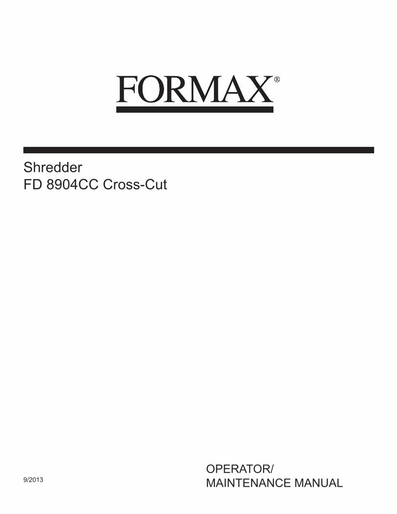
The machine number is specified on the nameplate on the shredder, shown above. Guarantee claims and inquiries cannot be processed if you do not quote the machine number.
Enter this number and the other data into the relevant fields of the nameplate shown here immediately after receipt of the shredder.
Machine Specs
Model: FD 8904CC Serial #: __________________
Motor 7.5KW (10HP)
Power 220V / 60Hz / 3-Phase
Sheet Capacity Up to 650 Sheets
Throat Width 21”
Weight 1,984 lbs.
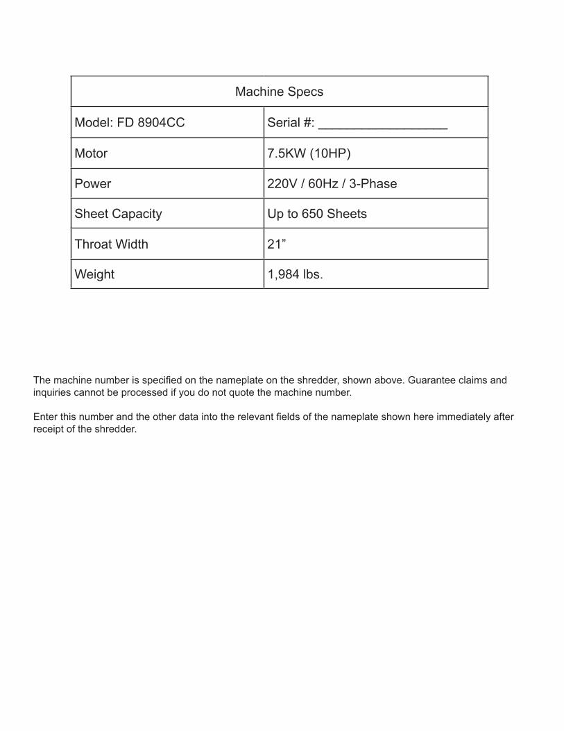
TABLE OF CONTENTS
TOPIC PAGE
Safety Precautions 1-2
Checking Safety Devices 3
Overview 4
Machine Characteristics 5
Cutting Data, Speed, Dimensions, Weight 5
Motor Specifications, Power Requirements 5
Installation 5
Installation: Space Requirements 6
Start-up: Main Switch and Control Panel 7
Operation, Oiling, Overloading 8
Emptying Waste Bin 9
Maintenance: Removing Side Covers 9
Maintenance: Conveyor Belt Maintenance 9-10
Maintenance: Lubricating Shredder Mechanisms 11
Maintenance: Exterior Cleaning 11
Parts Lists 12-19

“Work safety” symbol
This symbol marks all work safety notes in this manual which can endanger the health or life of operators. Please pay attention to this symbol and exercise particular care in such cases. Please also forward all work safety notes to other users. Apart from the instructions in this manual, you should also follow generally applicable safety and accident prevention guidelines.
Notes on work safety The FD 8904CC shredder has been inspected for safety. However, improper operation and misuse risk the following: • the health or life of the operator • the machine and other valuable equipment • the efficient operation of the shredder. The FD 8904CC employs state-of-the-art technology and is safe to operate. However, this machine can become hazardous if used incorrectly, by untrained staff or for purposes other than those for which it is designed.
• Material with a tendency to curl, e.g. tapes, cords, etc. should not be processed. • Keep long hair, loose clothes, ties, scarves, etc. away from paper feed opening. • Only one person should operate the shredder at a time. • Always follow local safety and accident prevention regulations when operating the shredder. • No pedestals or other raised surfaces may be placed in the vicinity of the machine if they alter the safety clearances. • All connecting cables must be laid in such a way that they cannot be tripped over. • Mechanical wearing parts must be inspected once a year.
“Attention” notes This icon marks information in this manual which requires particular attention including guidelines, regulations, instructions and correct working procedures intended to prevent damage to the machine and/or other equipment.
Safety Precautions
1

2
The FD 8904CC shredder is intended for shredding paper, cardboard, archive files, tapes, ribbons, CDs and magnetic disks. The hardened, solid-steel cutting rollers are unaffected by loose-leaf binders, paper clips and staples contained in these materials.
Any other use beyond the scope described here is regarded as not being in accordance with the instructions. The manufacturer will not be held liable for damage resulting from incorrect use; the user alone is responsible.
Users must also follow the assembly, dismantling, re-assembly, operation and maintenance procedures specified by the manufacturer. The operation, maintenance and repair of the machine must be performed only by trained personnel who are aware of the potential dangers. The relevant accident prevention regulations as well as other generally recognized rules concerning safety engineering and occupational safety must be observed.
• Each person responsible for assembling, dismantling and reassembling and maintenance (inspection, servicing, repair) of the shredder must have read and fully understood the entire operating manual, in particular the "Safety" section. • The shredder may only be operated, serviced and repaired by authorized, trained personnel. • The shut-down procedures specified in this manual must be followed during all assembly, dismantling and re-assembling, cleaning, and maintenance work. This type of work must be performed only when the machine is idle. • The drive of the FD 8904CC must be secured against unintentional switching-on before performing work on the machine. Set the main switch to "Off" and unplug machine from wall outlet. • After repair, check all protective devices to be sure they have been re-installed before operation. • Do not perform any work which may impair your safety while operating the machine. • Immediately report any changes which impair your safety to the person responsible. Shut the machine down until such damage has been resolved. • Before operating the shredder, ensure that it is in perfect working condition. • Ensure that the workplace around the FD 8904CC is always clean and safe. • The user must not make any conversions or changes on his own initiative which impair the safety of the FD 8904CC. Protective devices must not be removed or rendered inoperative.
• All work which is not directly connected to the normal operation of the machine must always be performed when the machine is idle. • Doors and flaps must not be opened until the machine is motionless. Observe safety labels! • Test the safety features after installing or repairing electrical components.
Checking the safety devices Check the safety devices: • at the start of each work shift (when operation is sporadic) • at least once a week in continuous operation • after each maintenance or repair Check the safety devices for:
• specified condition • specified location • safe attachment • specified function
Correct defects before you operate the shredder. 1. Immediately shut down the shredder if defects occur during operation and make sure the defects are corrected. 2. Do not modify or remove protective devices. Do not switch off protective devices. For safety reasons, modifications of the machine are not allowed.
Danger: Defective safety devices can cause serious accidents. If safety devices are not working properly, the shredder should immediately be put out of operation. Never reach into the cutting system while it is operating; you risk serious injury! Only when all safety devices are operating correctly can the shredder be used again.
Operate the shredder only when these devices have been checked and are in order.
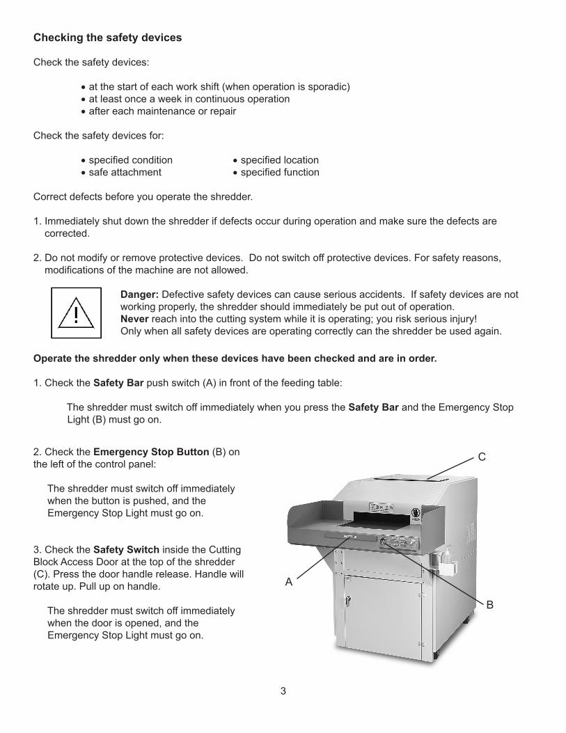
1. Check the Safety Bar push switch (A) in front of the feeding table:
The shredder must switch off immediately when you press the Safety Bar and the Emergency Stop Light (B) must go on.
2. Check the Emergency Stop Button (B) on the left of the control panel:
The shredder must switch off immediately when the button is pushed, and the Emergency Stop Light must go on.
3. Check the Safety Switch inside the Cutting Block Access Door at the top of the shredder (C). Press the door handle release. Handle will rotate up. Pull up on handle.
The shredder must switch off immediately when the door is opened, and the Emergency Stop Light must go on.
A
B
C
3
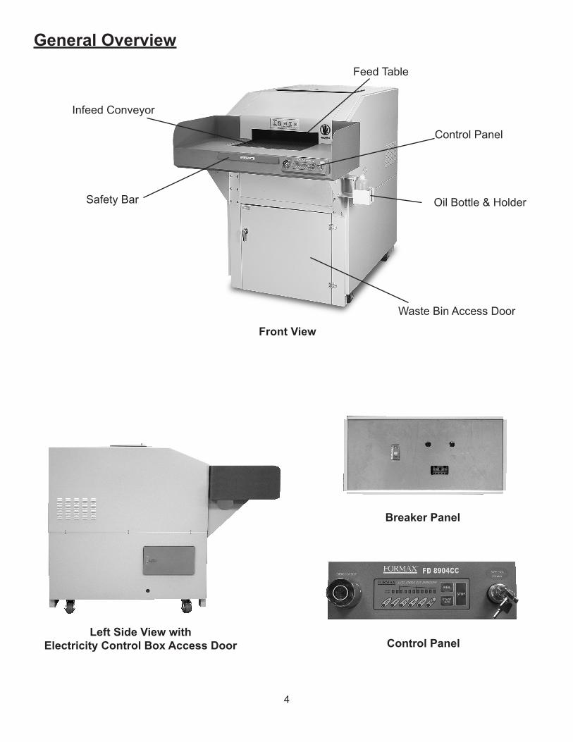
General Overview
Front View
Control Panel
Feed Table
Safety Bar
Left Side View withElectricity Control Box Access Door
4
Breaker Panel
Waste Bin Access Door
Control Panel
Infeed Conveyor
Oil Bottle & Holder
5
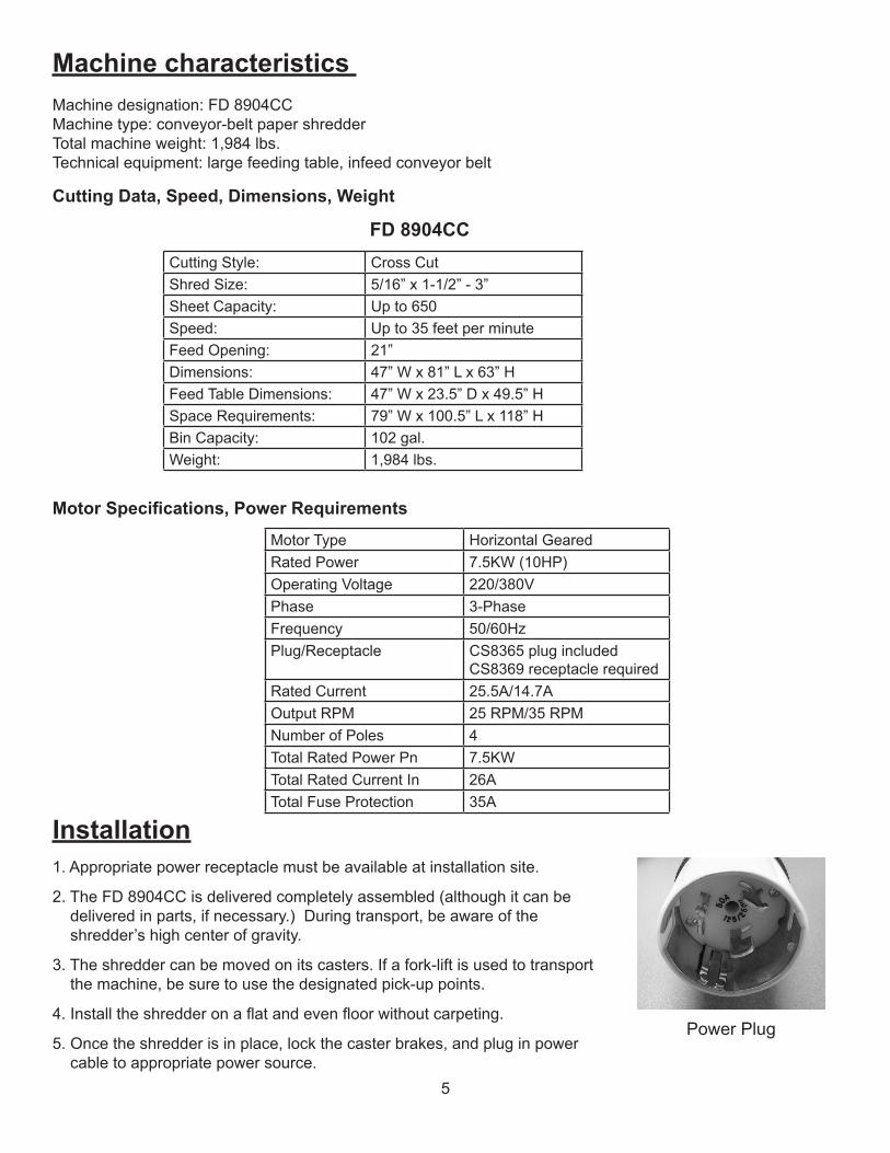
Machine characteristics Machine designation: FD 8904CCMachine type: conveyor-belt paper shredderTotal machine weight: 1,984 lbs. Technical equipment: large feeding table, infeed conveyor belt
Cutting Data, Speed, Dimensions, Weight
Cutting Style: Cross CutShred Size: 5/16” x 1-1/2” - 3”Sheet Capacity: Up to 650Speed: Up to 35 feet per minuteFeed Opening: 21”Dimensions: 47” W x 81” L x 63” HFeed Table Dimensions: 47” W x 23.5” D x 49.5” HSpace Requirements: 79” W x 100.5” L x 118” HBin Capacity: 102 gal.Weight: 1,984 lbs.
FD 8904CC
Motor Specifications, Power Requirements
Installation1. Appropriate power receptacle must be available at installation site.
2. The FD 8904CC is delivered completely assembled (although it can be delivered in parts, if necessary.) During transport, be aware of the shredder’s high center of gravity.
3. The shredder can be moved on its casters. If a fork-lift is used to transport the machine, be sure to use the designated pick-up points.
4. Install the shredder on a flat and even floor without carpeting.
5. Once the shredder is in place, lock the caster brakes, and plug in power cable to appropriate power source.
Motor Type Horizontal GearedRated Power 7.5KW (10HP)Operating Voltage 220/380VPhase 3-PhaseFrequency 50/60HzPlug/Receptacle CS8365 plug included
CS8369 receptacle requiredRated Current 25.5A/14.7AOutput RPM 25 RPM/35 RPMNumber of Poles 4Total Rated Power Pn 7.5KWTotal Rated Current In 26ATotal Fuse Protection 35A
Power Plug
6
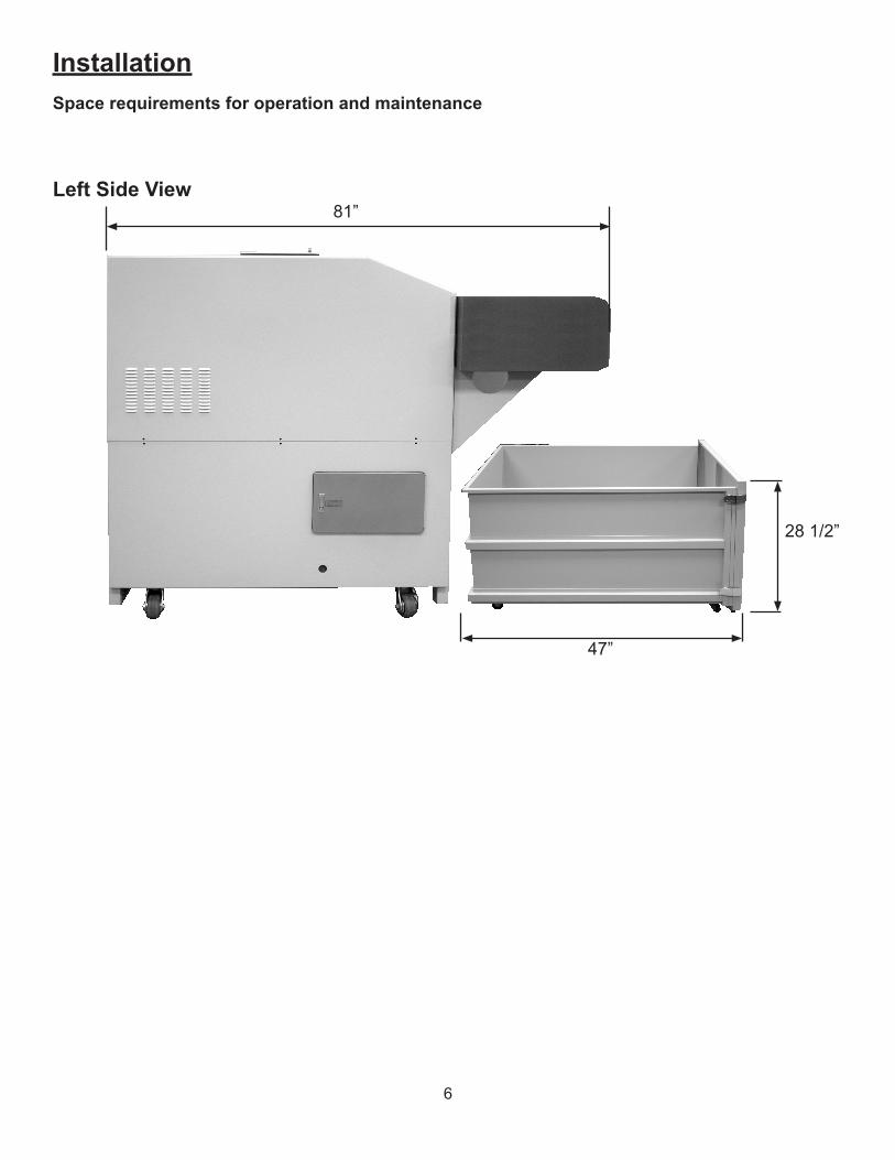
InstallationSpace requirements for operation and maintenance
Left Side View
28 1/2”
47”
81”
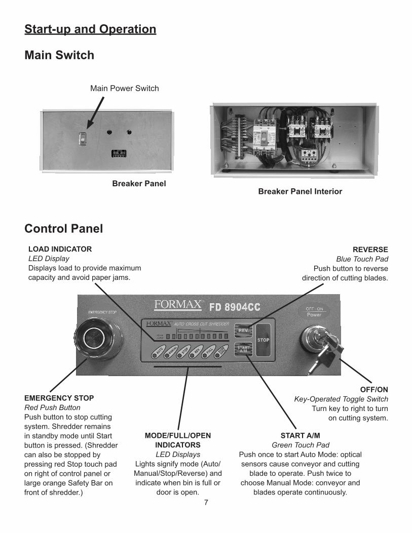
Control Panel
Start-up and Operation
Main Switch
MODE/FULL/OPEN INDICATORSLED Displays
Lights signify mode (Auto/Manual/Stop/Reverse) and indicate when bin is full or
door is open.
REVERSEBlue Touch Pad
Push button to reverse direction of cutting blades.
EMERGENCY STOPRed Push ButtonPush button to stop cutting system. Shredder remains in standby mode until Start button is pressed. (Shredder can also be stopped by pressing red Stop touch pad on right of control panel or large orange Safety Bar on front of shredder.)
START A/MGreen Touch Pad
Push once to start Auto Mode: optical sensors cause conveyor and cutting
blade to operate. Push twice to choose Manual Mode: conveyor and
blades operate continuously.
OFF/ONKey-Operated Toggle Switch
Turn key to right to turnon cutting system.
Main Power Switch
Breaker PanelBreaker Panel Interior
7
LOAD INDICATORLED DisplayDisplays load to provide maximum capacity and avoid paper jams.
8
Operation1. Set main switch to ON (page 7). Turn the Key OFF/ON toggle switch on the control panel to the ON position.
2. Press the START button. The conveyor will begin to move in the forward direction.
3. Place the material to be shredded on the feed table, then slide it onto the infeed conveyor belt, in appropriate stacks. (Up to 650 sheets.)
NOTE: If material is accidentally placed onto the conveyor belt, DO NOT REACH FOR IT. Instead, press the red STOP button (left side of control panel) or the Safety Stop Bar (front of feed table). When the shredder stops, press and hold the REVERSE button. The conveyor will operate in reverse, allowing safer access to the materials. The shredder will stop when the REVERSE button is released. To resume shredding, press STOP button, then the START button.
Turning off the shredder
1. To shut down the shredder, press the STOP button on the control panel.
2. Turn Key OFF/ON toggle switch on the control panel to the OFF position (to the left).
3. Open the electrical control panel door, and flip the main power switch DOWN to the off position.
Overloading the motor
If the shred capacity of the machine is exceeded (too large a stack of paper, etc), the shredder will stop automatically. To resume shredding:
1. Push and hold the REVERSE button until the paper or other material backs completely out of the shredder.
2. Press the red STOP button or the SAFETY BAR on the front of the machine, then divide the materials into smaller stacks.
3. Press the START button. The conveyor and cutting blades will begin to move.
4. Continue shredding, feeding less paper or fewer materials at a time.
Frequent Overloading
If the shredder is repeatedly overloaded, the motor can overheat, which will cause the shredder to switch off automatically. To resume shredding:
1. Allow the motor to cool down for approximately 20 - 30 minutes before using.
2. Once the motor has cooled sufficiently, resume shredding by following standard operating procedure.
NOTE:To maintain optimum performance and allow constant operation, avoid repeatedly overloading the shredder. This will prevent time-consuming reversing cycles, and will provide the highest possible throughput.
Oiling Cutting Blades with automatic EvenFlow Oiling System
The EvenFlow Oiler helps keep the cutting blades in peak operating condition by periodically applying oil to the blades.
1. To replace the oil bottle, unscrew and remove the cap from a new bottle of oil. Insert the hose and threaded screw cap. Tighten cap and place bottle in holding bracket on the right side of the shredder.
Emptying the Waste Bin
Shredded paper and particles accumulate in the shredder waste bin during normal operation. When the “Waste Bin Full” lamp lights, empty the waste bin.
1. Switch the shredder off by pressing the STOP button on the control panel, turn the Key OFF/ON toggle switch to the OFF position and flip the main power switch to the OFF position.
2. Grasp handle on waste bin and pull straight out. Gather sides of shredder bag using drawstring. Flip open two latches on front left of waste bin (see page 4), swing open door and slide bag out. Close and latch door. Empty and replace bag.
3. Push the waste bin in, turn power switches back on and resume shredding.
Maintenance and Inspection
9
Conveyor Belt Maintenance
• Checking Belt Tension When loaded with material, the conveyor belt must not slip, i.e. stand still when material is loaded. If the belt slips, it must be tightened. Contact the Formax Service Department for assistance.
• Checking Belt for Wear The upper surface of the conveyor belt can become worn over time. The belt must be replaced when the woven fabric inlay becomes visible. Contact the Formax Service Department for assistance.
• Cleaning the Conveyor Belt area The conveyor belt area must be cleaned once a month, or as needed to maintain optimal performance. 1. Switch off the shredder and unplug from wall outlet. 2. Remove the covers on both sides, revealing the cleaning openings in the conveyor belt area. 3. Use compressed air to blow out particles, or a vacuum to remove dirt and dust. 4. Re-install side covers.
NOTE: Paper clips in the shredded materials may increase the frequency of cleaning necessary, and may become caught in the sides of the belt.
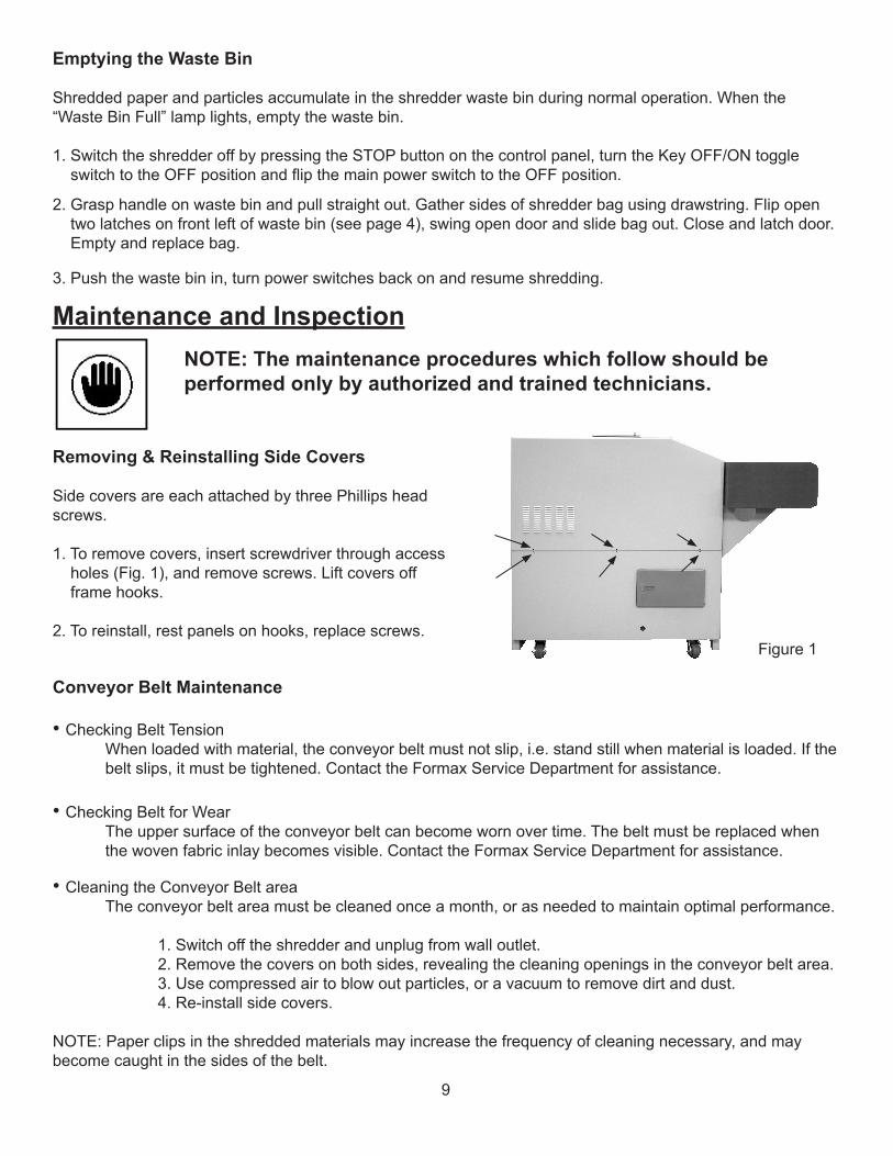
Removing & Reinstalling Side Covers
Side covers are each attached by three Phillips head screws. 1. To remove covers, insert screwdriver through access holes (Fig. 1), and remove screws. Lift covers off frame hooks.
2. To reinstall, rest panels on hooks, replace screws.
NOTE: The maintenance procedures which follow should be performed only by authorized and trained technicians.
Figure 1
10
• Cleaning the Conveyor Belt Tensioning Station The tensioning station must be cleaned once a month, or as needed to maintain optimal performance.
1. Switch off the shredder and unplug from wall outlet. 2. Remove the feed table and front panel of tensioning station (Fig. 2). 3. Remove particles and dirt. 4. Re-install the feed table and front panel of tensioning station.
Tensioning station adjuster
Fig. 2
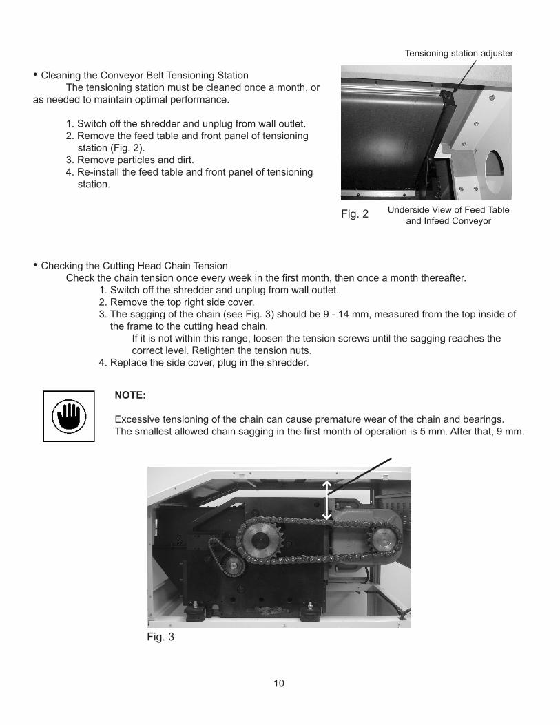
• Checking the Cutting Head Chain Tension Check the chain tension once every week in the first month, then once a month thereafter. 1. Switch off the shredder and unplug from wall outlet. 2. Remove the top right side cover. 3. The sagging of the chain (see Fig. 3) should be 9 - 14 mm, measured from the top inside of the frame to the cutting head chain. If it is not within this range, loosen the tension screws until the sagging reaches the correct level. Retighten the tension nuts. 4. Replace the side cover, plug in the shredder.
NOTE:
Excessive tensioning of the chain can cause premature wear of the chain and bearings. The smallest allowed chain sagging in the first month of operation is 5 mm. After that, 9 mm.
Fig. 3
Underside View of Feed Tableand Infeed Conveyor
11
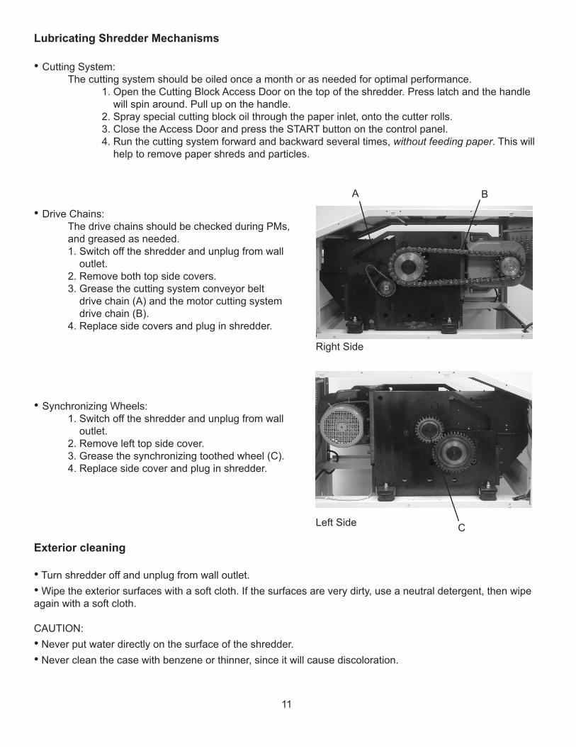
Exterior cleaning
• Turn shredder off and unplug from wall outlet.• Wipe the exterior surfaces with a soft cloth. If the surfaces are very dirty, use a neutral detergent, then wipe again with a soft cloth.
CAUTION:• Never put water directly on the surface of the shredder.• Never clean the case with benzene or thinner, since it will cause discoloration.
Lubricating Shredder Mechanisms
• Cutting System: The cutting system should be oiled once a month or as needed for optimal performance. 1. Open the Cutting Block Access Door on the top of the shredder. Press latch and the handle will spin around. Pull up on the handle. 2. Spray special cutting block oil through the paper inlet, onto the cutter rolls. 3. Close the Access Door and press the START button on the control panel. 4. Run the cutting system forward and backward several times, without feeding paper. This will help to remove paper shreds and particles.
A
• Drive Chains: The drive chains should be checked during PMs, and greased as needed. 1. Switch off the shredder and unplug from wall outlet. 2. Remove both top side covers. 3. Grease the cutting system conveyor belt drive chain (A) and the motor cutting system drive chain (B). 4. Replace side covers and plug in shredder.
B
• Synchronizing Wheels: 1. Switch off the shredder and unplug from wall outlet. 2. Remove left top side cover. 3. Grease the synchronizing toothed wheel (C). 4. Replace side cover and plug in shredder.
C
Right Side
Left Side
12
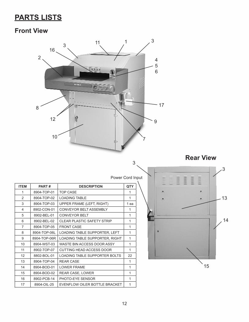
PARTS LISTS
ITEM PART # DESCRIPTION QTY1 8904-TOP-01 TOP CASE 1
2 8904-TOP-02 LOADING TABLE 1
3 8904-TOP-03 UPPER FRAME (LEFT, RIGHT) 1 ea
4 8902-CON-01 CONVEYOR BELT ASSEMBLY 1
5 8902-BEL-01 CONVEYOR BELT 1
6 8902-BEL-02 CLEAR PLASTIC SAFETY STRIP 1
7 8904-TOP-05 FRONT CASE 1
8 8904-TOP-06L LOADING TABLE SUPPORTER, LEFT 1
9 8904-TOP-06R LOADING TABLE SUPPORTER, RIGHT 1
10 8904-WST-03 WASTE BIN ACCESS DOOR ASSY 1
11 8902-TOP-07 CUTTING HEAD ACCESS DOOR 1
12 8802-BOL-01 LOADING TABLE SUPPORTER BOLTS 22
13 8904-TOP-04 REAR CASE 1
14 8904-BOD-01 LOWER FRAME 1
15 8904-BOD-02 REAR CASE, LOWER 1
16 8902-PCB-14 PHOTO-EYE SENSOR 1
17 8904-OIL-25 EVENFLOW OILER BOTTLE BRACKET 1
Rear View3
3
14
15
Power Cord Input
13
2
3
7
1
456
8
Front View
12
3
9
10
1116
17
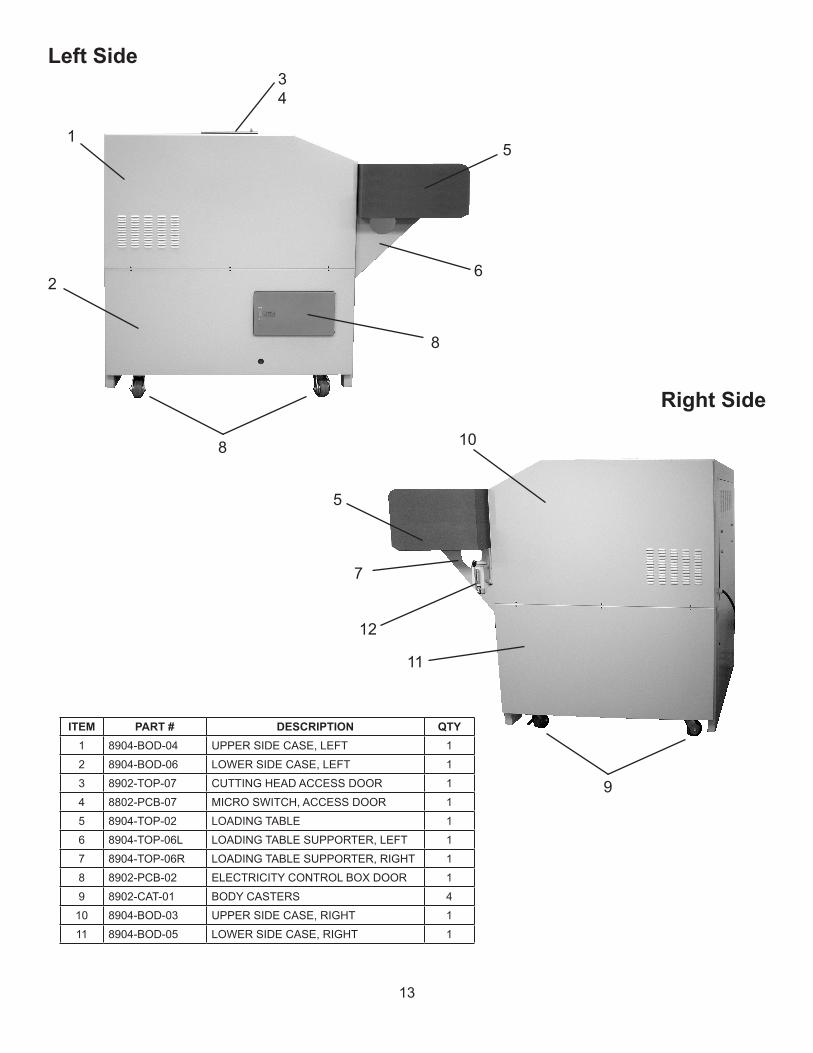
ITEM PART # DESCRIPTION QTY1 8904-BOD-04 UPPER SIDE CASE, LEFT 1
2 8904-BOD-06 LOWER SIDE CASE, LEFT 1
3 8902-TOP-07 CUTTING HEAD ACCESS DOOR 1
4 8802-PCB-07 MICRO SWITCH, ACCESS DOOR 1
5 8904-TOP-02 LOADING TABLE 1
6 8904-TOP-06L LOADING TABLE SUPPORTER, LEFT 1
7 8904-TOP-06R LOADING TABLE SUPPORTER, RIGHT 1
8 8902-PCB-02 ELECTRICITY CONTROL BOX DOOR 1
9 8902-CAT-01 BODY CASTERS 4
10 8904-BOD-03 UPPER SIDE CASE, RIGHT 1
11 8904-BOD-05 LOWER SIDE CASE, RIGHT 1
13
Left Side
1
2
34
5
8
6
8
Right Side
10
9
11
5
7
12
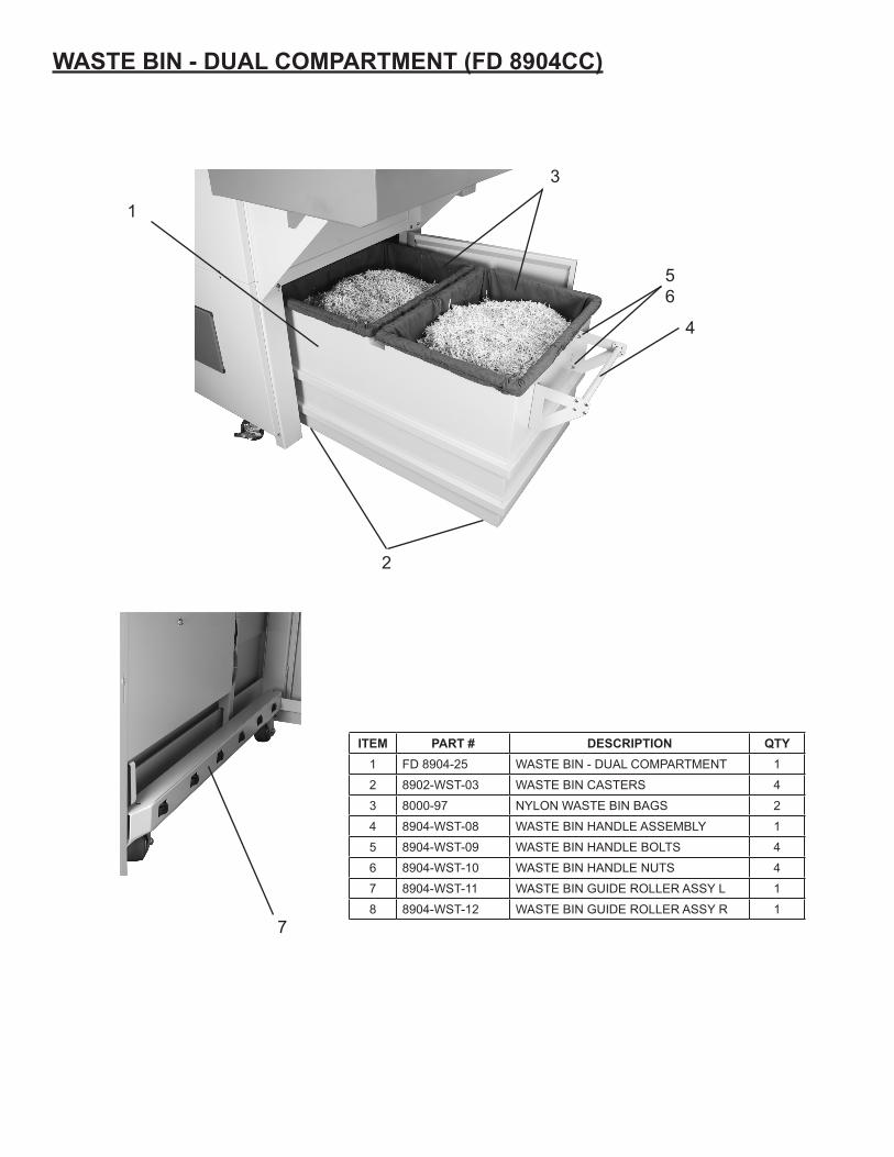
ITEM PART # DESCRIPTION QTY1 FD 8904-25 WASTE BIN - DUAL COMPARTMENT 1
2 8902-WST-03 WASTE BIN CASTERS 4
3 8000-97 NYLON WASTE BIN BAGS 2
4 8904-WST-08 WASTE BIN HANDLE ASSEMBLY 1
5 8904-WST-09 WASTE BIN HANDLE BOLTS 4
6 8904-WST-10 WASTE BIN HANDLE NUTS 4
7 8904-WST-11 WASTE BIN GUIDE ROLLER ASSY L 1
8 8904-WST-12 WASTE BIN GUIDE ROLLER ASSY R 1
WASTE BIN - DUAL COMPARTMENT (FD 8904CC)
3
2
1
4
56
7
14
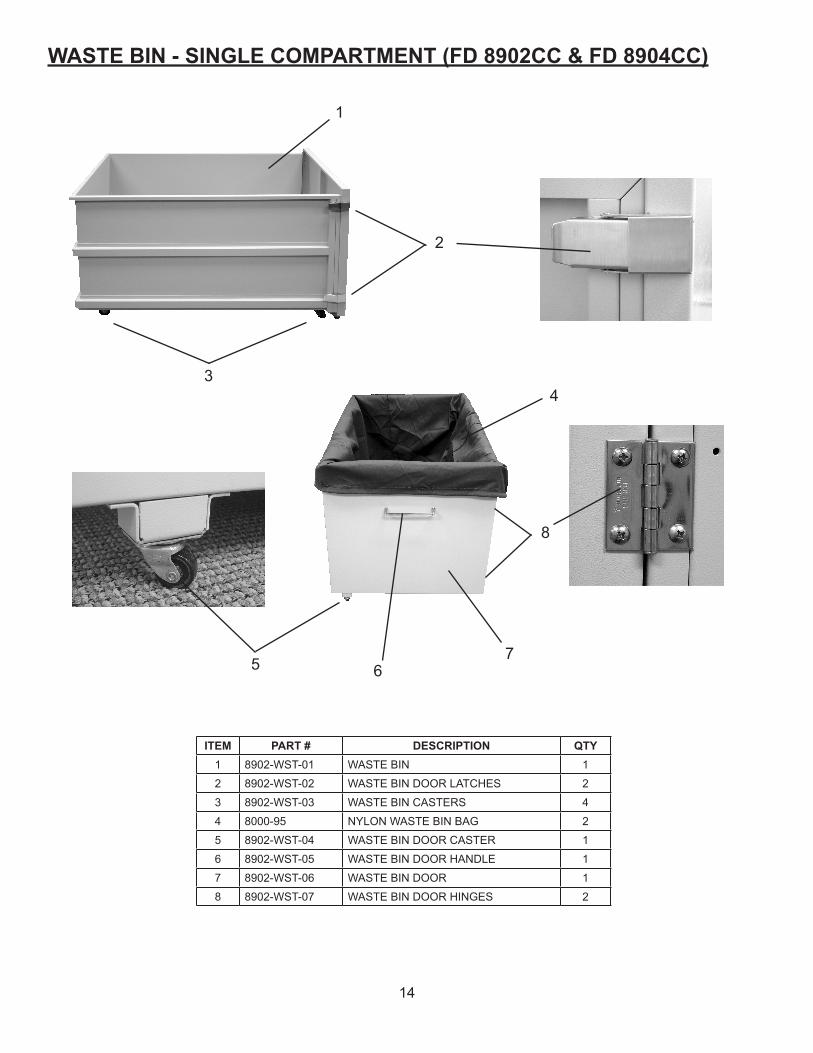
ITEM PART # DESCRIPTION QTY1 8902-WST-01 WASTE BIN 1
2 8902-WST-02 WASTE BIN DOOR LATCHES 2
3 8902-WST-03 WASTE BIN CASTERS 4
4 8000-95 NYLON WASTE BIN BAG 2
5 8902-WST-04 WASTE BIN DOOR CASTER 1
6 8902-WST-05 WASTE BIN DOOR HANDLE 1
7 8902-WST-06 WASTE BIN DOOR 1
8 8902-WST-07 WASTE BIN DOOR HINGES 2
WASTE BIN - SINGLE COMPARTMENT (FD 8902CC & FD 8904CC)
1
2
3
8
75 6
4
15
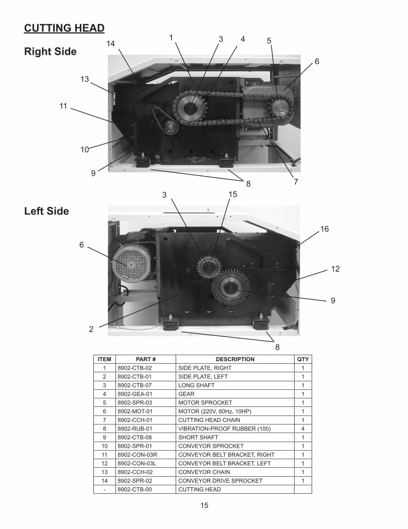
ITEM PART # DESCRIPTION QTY1 8902-CTB-02 SIDE PLATE, RIGHT 12 8902-CTB-01 SIDE PLATE, LEFT 13 8902-CTB-07 LONG SHAFT 14 8902-GEA-01 GEAR 15 8902-SPR-03 MOTOR SPROCKET 16 8902-MOT-01 MOTOR (220V, 60Hz, 10HP) 17 8902-CCH-01 CUTTING HEAD CHAIN 18 8902-RUB-01 VIBRATION-PROOF RUBBER (100) 49 8902-CTB-08 SHORT SHAFT 110 8902-SPR-01 CONVEYOR SPROCKET 111 8902-CON-03R CONVEYOR BELT BRACKET, RIGHT 112 8902-CON-03L CONVEYOR BELT BRACKET, LEFT 113 8902-CCH-02 CONVEYOR CHAIN 114 8902-SPR-02 CONVEYOR DRIVE SPROCKET 1- 8902-CTB-00 CUTTING HEAD
Left Side
Right Side
CUTTING HEAD1
6
16
10
78
53
11
13
9
2
15
6
14
3
12
4
8
9
16
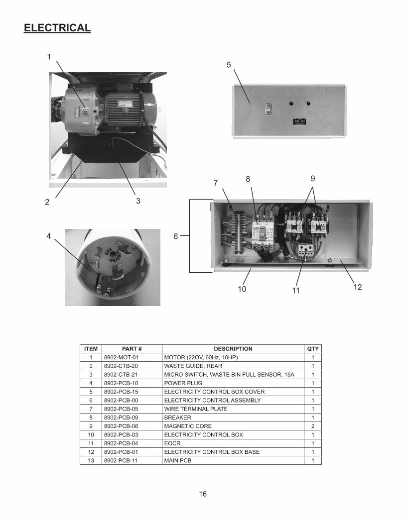
ITEM PART # DESCRIPTION QTY1 8902-MOT-01 MOTOR (22OV, 60Hz, 10HP) 12 8902-CTB-20 WASTE GUIDE, REAR 13 8902-CTB-21 MICRO SWITCH, WASTE BIN FULL SENSOR, 15A 14 8902-PCB-10 POWER PLUG 15 8902-PCB-15 ELECTRICITY CONTROL BOX COVER 16 8902-PCB-00 ELECTRICITY CONTROL ASSEMBLY 17 8902-PCB-05 WIRE TERMINAL PLATE 18 8902-PCB-09 BREAKER 19 8902-PCB-06 MAGNETIC CORE 2
10 8902-PCB-03 ELECTRICITY CONTROL BOX 111 8902-PCB-04 EOCR 112 8902-PCB-01 ELECTRICITY CONTROL BOX BASE 113 8902-PCB-11 MAIN PCB 1
1
10
2
9
5
6
3
ELECTRICAL
4
87
11 12
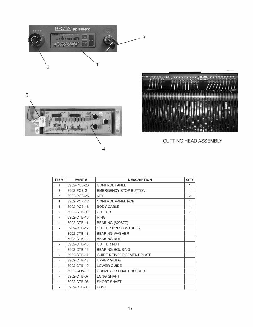
ITEM PART # DESCRIPTION QTY1 8902-PCB-23 CONTROL PANEL 12 8902-PCB-24 EMERGENCY STOP BUTTON 13 8902-PCB-25 KEY 24 8902-PCB-12 CONTROL PANEL PCB 15 8902-PCB-16 BODY CABLE 1- 8902-CTB-09 CUTTER -- 8902-CTB-10 RING- 8902-CTB-11 BEARING (6208ZZ)- 8902-CTB-12 CUTTER PRESS WASHER- 8902-CTB-13 BEARING WASHER- 8902-CTB-14 BEARING NUT- 8902-CTB-15 CUTTER NUT- 8902-CTB-16 BEARING HOUSING- 8902-CTB-17 GUIDE REINFORCEMENT PLATE- 8902-CTB-18 UPPER GUIDE- 8902-CTB-19 LOWER GUIDE- 8902-CON-02 CONVEYOR SHAFT HOLDER- 8902-CTB-07 LONG SHAFT- 8902-CTB-08 SHORT SHAFT- 8902-CTB-03 POST
17
1
4
2
3
5
CUTTING HEAD ASSEMBLY
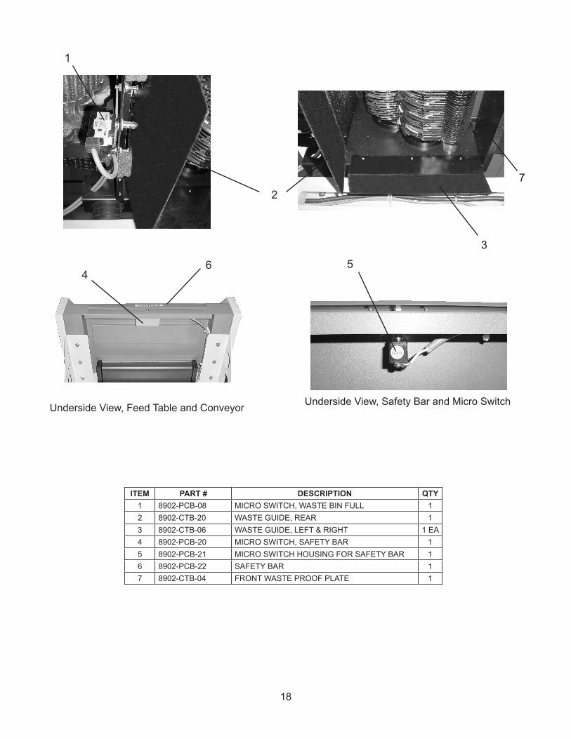
ITEM PART # DESCRIPTION QTY1 8902-PCB-08 MICRO SWITCH, WASTE BIN FULL 12 8902-CTB-20 WASTE GUIDE, REAR 13 8902-CTB-06 WASTE GUIDE, LEFT & RIGHT 1 EA4 8902-PCB-20 MICRO SWITCH, SAFETY BAR 15 8902-PCB-21 MICRO SWITCH HOUSING FOR SAFETY BAR 16 8902-PCB-22 SAFETY BAR 17 8902-CTB-04 FRONT WASTE PROOF PLATE 1
5
1
4
2
3
Underside View, Feed Table and Conveyor Underside View, Safety Bar and Micro Switch
18
7
6
19
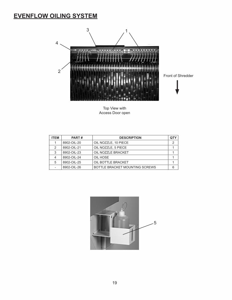
ITEM PART # DESCRIPTION QTY1 8902-OIL-20 OIL NOZZLE, 10 PIECE 22 8902-OIL-21 OIL NOZZLE, 5 PIECE 13 8902-OIL-23 OIL NOZZLE BRACKET 14 8902-OIL-24 OIL HOSE 15 8902-OIL-25 OIL BOTTLE BRACKET 1- 8902-OIL-26 BOTTLE BRACKET MOUNTING SCREWS 6
EVENFLOW OILING SYSTEM
1
2
4
3
Front of Shredder
Top View with Access Door open
5
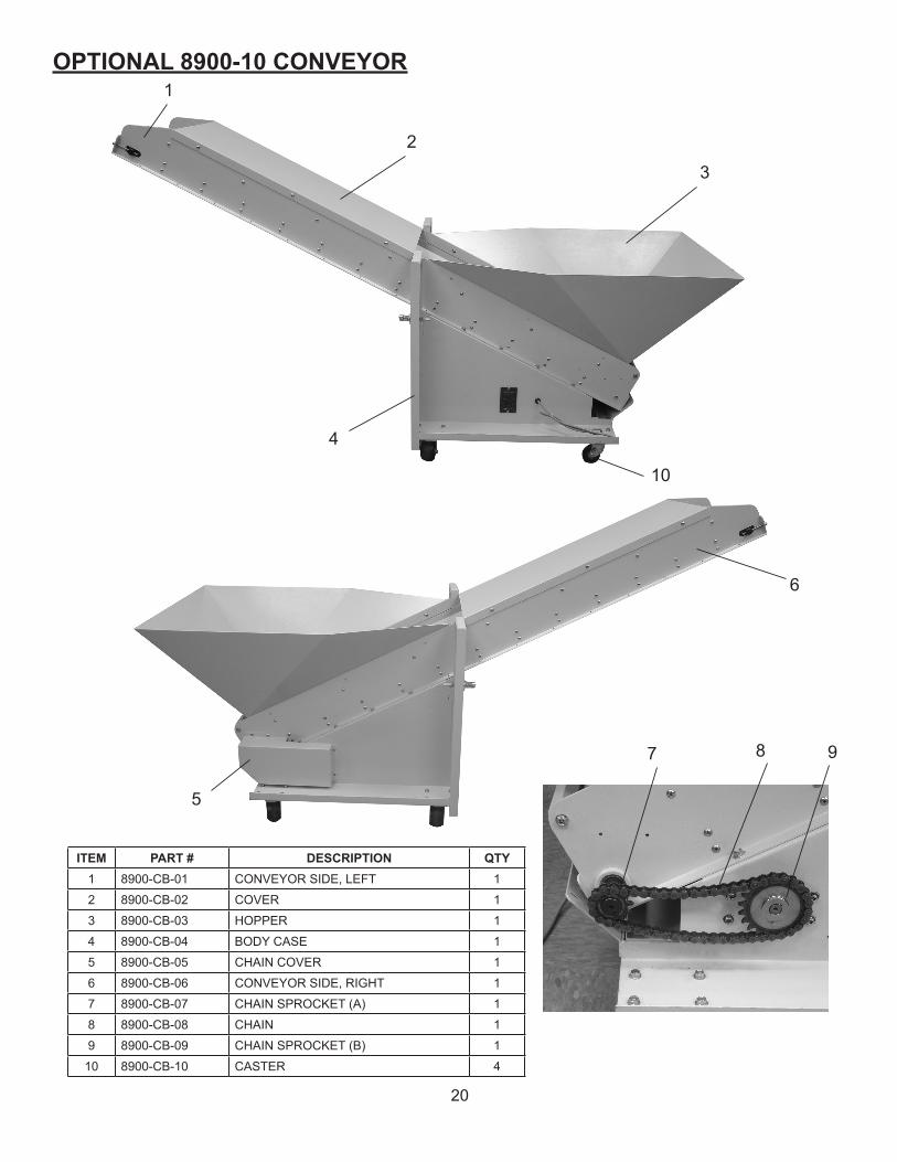
OPTIONAL 8900-10 CONVEYOR
ITEM PART # DESCRIPTION QTY1 8900-CB-01 CONVEYOR SIDE, LEFT 1
2 8900-CB-02 COVER 1
3 8900-CB-03 HOPPER 1
4 8900-CB-04 BODY CASE 1
5 8900-CB-05 CHAIN COVER 1
6 8900-CB-06 CONVEYOR SIDE, RIGHT 1
7 8900-CB-07 CHAIN SPROCKET (A) 1
8 8900-CB-08 CHAIN 1
9 8900-CB-09 CHAIN SPROCKET (B) 1
10 8900-CB-10 CASTER 4
987
5
6
1
2
3
4
10
20
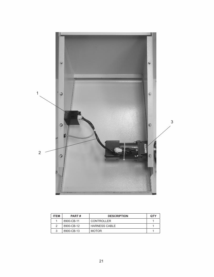
ITEM PART # DESCRIPTION QTY1 8900-CB-11 CONTROLLER 1
2 8900-CB-12 HARNESS CABLE 1
3 8900-CB-13 MOTOR 1
3
2
1
21
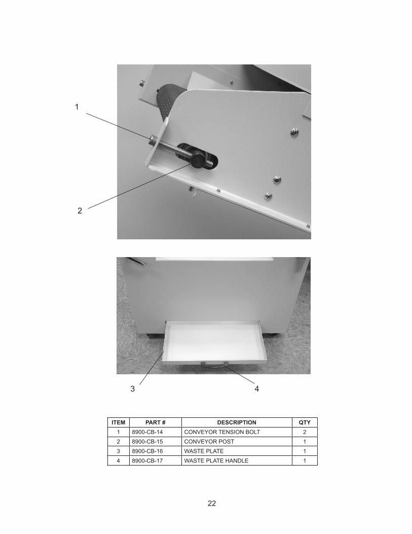
ITEM PART # DESCRIPTION QTY1 8900-CB-14 CONVEYOR TENSION BOLT 2
2 8900-CB-15 CONVEYOR POST 1
3 8900-CB-16 WASTE PLATE 1
4 8900-CB-17 WASTE PLATE HANDLE 1
1
2
3 4
22
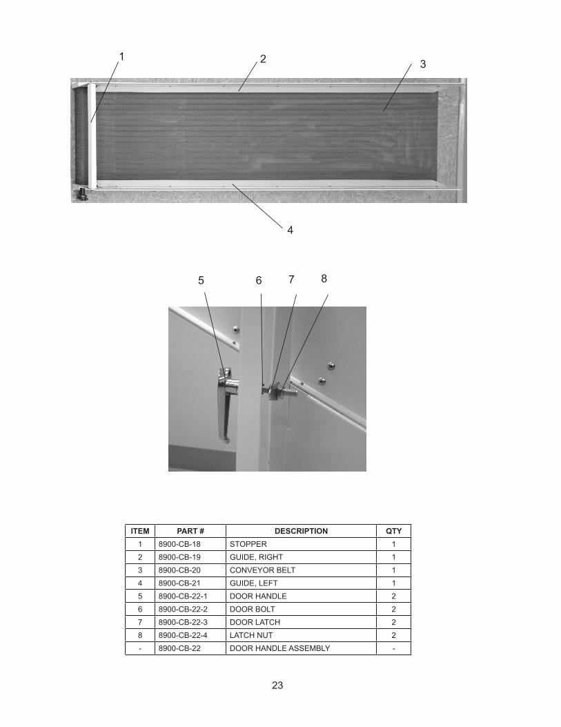
ITEM PART # DESCRIPTION QTY1 8900-CB-18 STOPPER 1
2 8900-CB-19 GUIDE, RIGHT 1
3 8900-CB-20 CONVEYOR BELT 1
4 8900-CB-21 GUIDE, LEFT 1
5 8900-CB-22-1 DOOR HANDLE 2
6 8900-CB-22-2 DOOR BOLT 2
7 8900-CB-22-3 DOOR LATCH 2
8 8900-CB-22-4 LATCH NUT 2
- 8900-CB-22 DOOR HANDLE ASSEMBLY -
1 2 3
4
8765
23