Short-term stability of an excavation in marine...
8
Short-term stability of an excavation in marine clay A. Fasano, A. Nikolic, J. Cook & P. Scott Buro Happold, London, UK ABSTRACT The paper focuses on the short term stability of a 17m deep (approaching 200 x 200m in plan) retained excavation in marine clay. The stability of the excavation is mainly affected by the undrained strength of this clay layer, which in turn is strongly related to its stress history and overconsolidation state. In the first section the site ground conditions are described and key laboratory and in situ testing experimental data are presented. The second section introduces the short term excavation stability conditions. A comparison between classic Limit Equilibrium methods and simple Finite Element solutions is undertaken. The significance of considering strength anisotropy is discussed. RÉSUMÉ Le document se concentre sur la stabilité à court terme d’une excavation soutenue de 17m de profondeur (200 x 200 m sur plan environ) en argile marine. La stabilité de l'excavation est principalement affectée par la force non drainée de cette argile, qui, à son tour, est fortement liée à ses contraintes et a son état de surconsolidation. Dans le Chapitre 1 sont décrites les conditions du terrain et des données expérimentales de laboratoires et d’essais in situ. Le Chapitre 2 présente les conditions à court terme de stabilité d’excavation. Une comparaison entre méthodes classiques de limite d’équilibre et solutions simples des éléments finis est effectuée. L'importance de l'examen de la force d'anisotropie est discutée. 1 INTRODUCTION Deep excavations in normally consolidated clay are notoriously challenging in terms of soil mechanics and engineering behaviour. The prime concerns relate to the stability assessment and the difficulty in evaluating excavation performance under serviceability conditions. This paper focuses on the stability aspects of a significant deep excavation in marine clay. Performance under serviceability conditions is not within the scope of this paper however, the authors wish to highlight the importance of appropriate selection of material constitutive models when undertaking any form of numerical modelling to this effect. The excavation concerned is up to 17m in depth and approaches 200m x 200m in plan. The retention system comprises a reinforced concrete diaphragm wall supported by five levels of grouted ground anchors. The excavation is set in an urban environment and is surrounded by existing buildings and infrastructure. The authors aim to emphasise the importance of characterising the marine clay which dominates the stability and behaviour of the excavation concerned. Various methods for assessing the base and global stability of the excavation were reviewed as part of this study. A selection of these Limit Equilibrium based methods are detailed and compared in this paper. The authors proceed to compare the results from the more traditional Limit Equilibrium analyses with simple plane strain Finite Element assessments. The significance of undrained shear strength anisotropy of the marine clay and understanding of stress paths in relation to in situ and laboratory testing is presented in view of the excavation stability mechanisms. 1.1 Ground Conditions Ground conditions at the site typically comprise 1m of Made Ground overlying a layer of dense sands and gravels to an approximate depth of 5m below ground level. The marine clay underlies the sands and gravels with an overall thickness ranging from 25m to 35m. The marine clay in turn is underlain by a thin layer of predominantly cohesionless Glacial Till with bedrock at depth. The groundwater monitoring indicated that a perched water table was typically located at 1.5m below ground level within the sands and gravels. The pore water pressure profile within the marine clay was established with a series of vibrating wire piezometers. A hydrostatic profile with depth was measured which was in continuity with the overlying perched water table and underlying groundwater in the Glacial Till aquifer. 1.2 Marine Clay Site Stress History In view of the ground conditions at the site, it is evident that deep excavation stability is critically dependent on the marine clay performance. For this reason, careful characterization of the material is essential in order to evaluate appropriate parameters for both ultimate and serviceability limit state analyses. The marine clay stratum is characterised at the top by a relatively stiff crust, overconsolidated due to historical fluctuations of the groundwater table. The overconsolidation ratio (OCR) reduces with depth (Figure 2) and the lower portion of the stratum is normally consolidated. Undisturbed samples of the overconsolidated crust and the underlying normally consolidated material are compared in Figure 1. The normally consolidated material exhibits well defined 149 GeoHalifax2009/GéoHalifax2009
Transcript of Short-term stability of an excavation in marine...

Short-term stability of an excavation in marine clay
A. Fasano, A. Nikolic, J. Cook & P. Scott Buro Happold, London, UK ABSTRACT The paper focuses on the short term stability of a 17m deep (approaching 200 x 200m in plan) retained excavation in marine clay. The stability of the excavation is mainly affected by the undrained strength of this clay layer, which in turn is strongly related to its stress history and overconsolidation state. In the first section the site ground conditions are described and key laboratory and in situ testing experimental data are presented. The second section introduces the short term excavation stability conditions. A comparison between classic Limit Equilibrium methods and simple Finite Element solutions is undertaken. The significance of considering strength anisotropy is discussed. RÉSUMÉ Le document se concentre sur la stabilité à court terme d’une excavation soutenue de 17m de profondeur (200 x 200 m sur plan environ) en argile marine. La stabilité de l'excavation est principalement affectée par la force non drainée de cette argile, qui, à son tour, est fortement liée à ses contraintes et a son état de surconsolidation. Dans le Chapitre 1 sont décrites les conditions du terrain et des données expérimentales de laboratoires et d’essais in situ. Le Chapitre 2 présente les conditions à court terme de stabilité d’excavation. Une comparaison entre méthodes classiques de limite d’équilibre et solutions simples des éléments finis est effectuée. L'importance de l'examen de la force d'anisotropie est discutée. 1 INTRODUCTION Deep excavations in normally consolidated clay are notoriously challenging in terms of soil mechanics and engineering behaviour. The prime concerns relate to the stability assessment and the difficulty in evaluating excavation performance under serviceability conditions. This paper focuses on the stability aspects of a significant deep excavation in marine clay. Performance under serviceability conditions is not within the scope of this paper however, the authors wish to highlight the importance of appropriate selection of material constitutive models when undertaking any form of numerical modelling to this effect.
The excavation concerned is up to 17m in depth and approaches 200m x 200m in plan. The retention system comprises a reinforced concrete diaphragm wall supported by five levels of grouted ground anchors. The excavation is set in an urban environment and is surrounded by existing buildings and infrastructure.
The authors aim to emphasise the importance of characterising the marine clay which dominates the stability and behaviour of the excavation concerned. Various methods for assessing the base and global stability of the excavation were reviewed as part of this study. A selection of these Limit Equilibrium based methods are detailed and compared in this paper. The authors proceed to compare the results from the more traditional Limit Equilibrium analyses with simple plane strain Finite Element assessments. The significance of undrained shear strength anisotropy of the marine clay and understanding of stress paths in relation to in situ and laboratory testing is presented in view of the excavation stability mechanisms.
1.1 Ground Conditions Ground conditions at the site typically comprise 1m of Made Ground overlying a layer of dense sands and gravels to an approximate depth of 5m below ground level. The marine clay underlies the sands and gravels with an overall thickness ranging from 25m to 35m. The marine clay in turn is underlain by a thin layer of predominantly cohesionless Glacial Till with bedrock at depth.
The groundwater monitoring indicated that a perched water table was typically located at 1.5m below ground level within the sands and gravels. The pore water pressure profile within the marine clay was established with a series of vibrating wire piezometers. A hydrostatic profile with depth was measured which was in continuity with the overlying perched water table and underlying groundwater in the Glacial Till aquifer.
1.2 Marine Clay Site Stress History In view of the ground conditions at the site, it is evident that deep excavation stability is critically dependent on the marine clay performance. For this reason, careful characterization of the material is essential in order to evaluate appropriate parameters for both ultimate and serviceability limit state analyses.
The marine clay stratum is characterised at the top by a relatively stiff crust, overconsolidated due to historical fluctuations of the groundwater table. The overconsolidation ratio (OCR) reduces with depth (Figure 2) and the lower portion of the stratum is normally consolidated. Undisturbed samples of the overconsolidated crust and the underlying normally consolidated material are compared in Figure 1. The normally consolidated material exhibits well defined
149
GeoHalifax2009/GéoHalifax2009
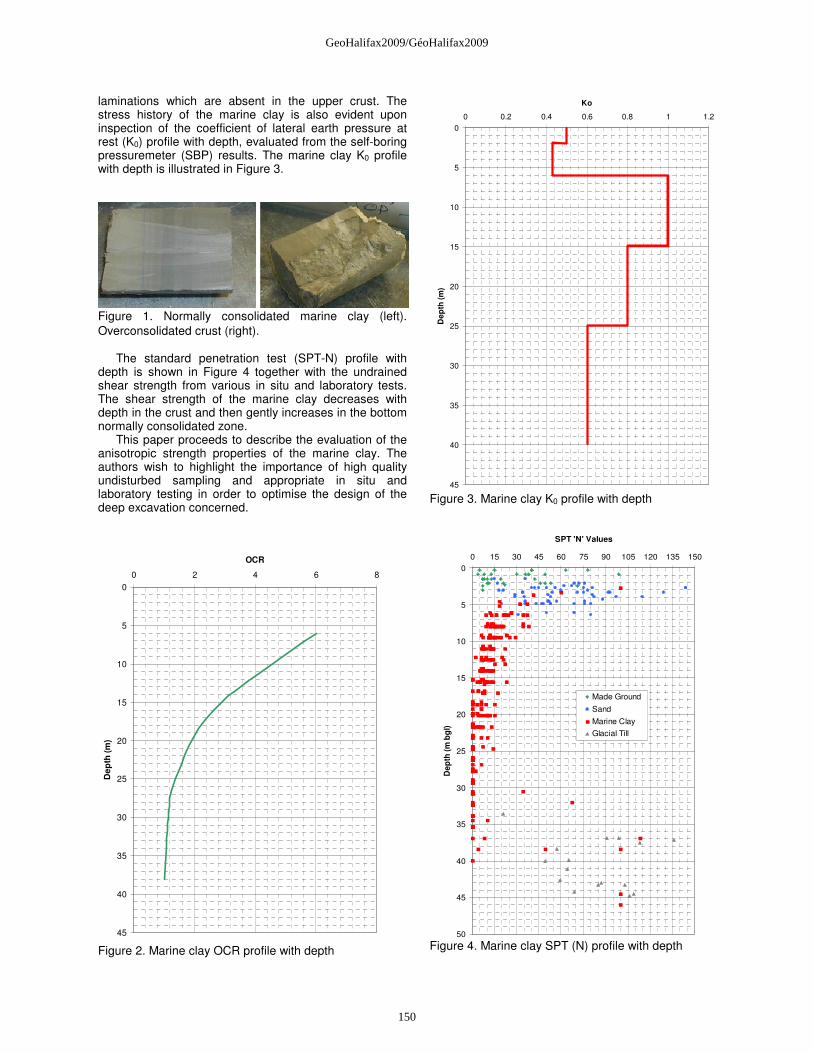
laminations which are absent in the upper crust. The stress history of the marine clay is also evident upon inspection of the coefficient of lateral earth pressure at rest (K0) profile with depth, evaluated from the self-boring pressuremeter (SBP) results. The marine clay K0 profile with depth is illustrated in Figure 3.
Figure 1. Normally consolidated marine clay (left). Overconsolidated crust (right).
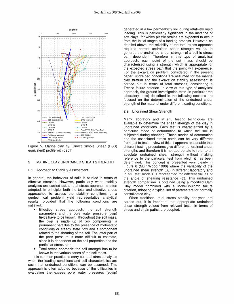
The standard penetration test (SPT-N) profile with depth is shown in Figure 4 together with the undrained shear strength from various in situ and laboratory tests. The shear strength of the marine clay decreases with depth in the crust and then gently increases in the bottom normally consolidated zone.
This paper proceeds to describe the evaluation of the anisotropic strength properties of the marine clay. The authors wish to highlight the importance of high quality undisturbed sampling and appropriate in situ and laboratory testing in order to optimise the design of the deep excavation concerned.
0
5
10
15
20
25
30
35
40
45
0 2 4 6 8
OCR
De
pth
(m
)
Figure 2. Marine clay OCR profile with depth
0
5
10
15
20
25
30
35
40
45
0 0.2 0.4 0.6 0.8 1 1.2
Ko
De
pth
(m
)
Figure 3. Marine clay K0 profile with depth
0
5
10
15
20
25
30
35
40
45
50
0 15 30 45 60 75 90 105 120 135 150
SPT 'N' Values
De
pth
(m
bg
l)
Made Ground
Sand
Marine Clay
Glacial Till
Figure 4. Marine clay SPT (N) profile with depth
150
GeoHalifax2009/GéoHalifax2009
0
5
10
15
20
25
30
35
40
45
50
0 50 100 150 200
Su (kPa)
Dep
th (
m b
gl)
DSS lower bound DSS Upper bound
DSS Best Estimate CPTU (average)
CPTU-1 CPTU-2
CPTU-3B CPTU-4
CPTU-5A CPTU-6
CPTU-7 Peak FVT-1 (Field Vane Test)
Peak FVT-2 (Field Vane Test) Peak FVT B103 (Field Vane Test)
Field Vane (average) DSS OCR=1
DSS Design Profile TC Design Profile
TE Design Profile
Figure 5. Marine clay Su (Direct Simple Shear (DSS) equivalent) profile with depth 2 MARINE CLAY UNDRAINED SHEAR STRENGTH 2.1 Approach to Stability Assessment In general, the behaviour of soils is studied in terms of effective stresses. However, particularly when stability analyses are carried out, a total stress approach is often adopted. In principle, both the total and effective stress approaches to assess the stability conditions of a geotechnical problem yield representative analytical results, provided that the following conditions are satisfied:
• Effective stress approach: the soil strength parameters and the pore water pressure (pwp) fields have to be known. Throughout the soil mass, the pwp is made up of two components, a permanent part due to the presence of hydrostatic conditions or steady state flow and a component related to the shearing of the soil. The latter part of the pore pressure is more difficult to estimate, since it is dependent on the soil properties and the particular stress path.
• Total stress approach: the soil strength has to be known in the various zones of the soil mass.
It is common practice to carry out total stress analyses when the loading conditions and soil characteristics are such that undrained conditions can be assumed. This approach is often adopted because of the difficulties in evaluating the excess pore water pressures (epwp)
generated in a low permeability soil during relatively rapid loading. This is particularly significant in the instance of soft clays, for which plastic strains are expected to occur from the initial stages of a loading process. However, as detailed above, the reliability of the total stress approach requires correct undrained shear strength values. In general, the undrained shear strength of a soil is stress path dependent. Therefore in this type of analytical approach, each point of the soil mass should be characterised using a strength which is appropriate for the expected stress path that the point will experience. For the excavation problem considered in the present paper, undrained conditions are assumed for the marine clay stratum and the excavation stability assessment is carried out in terms of total stresses, considering a Tresca failure criterion. In view of this type of analytical approach, the ground investigation tests (in particular the laboratory tests) described in the following sections are focused on the determination of the undrained shear strength of the material under different loading conditions. 2.2 Undrained Shear Strength Many laboratory and in situ testing techniques are available to determine the shear strength of the clay in undrained conditions. Each test is characterized by a particular mode of deformation to which the soil is subjected during shearing. These modes of deformation and the associated stress paths can be very different from test to test. In view of this, it appears reasonable that different testing procedures give different undrained shear strengths and therefore it is not appropriate to refer to an absolute undrained shear strength without making reference to the particular test from which it has been determined. This concept is presented very clearly in Figure 6 (Muir Wood 1990) where the variability of the undrained shear strength (Su) in different laboratory and in situ test models is represented for different values of the angle of shearing resistance (φ’). This undrained strength comparison is obtained using a modified Cam Clay model combined with a Mohr-Coulomb failure criterion, adopting a typical set of parameters for normally consolidated clay.
When traditional total stress stability analyses are carried out, it is important that appropriate undrained shear strength values from relevant tests, in terms of stress and strain paths, are adopted.
151
GeoHalifax2009/GéoHalifax2009
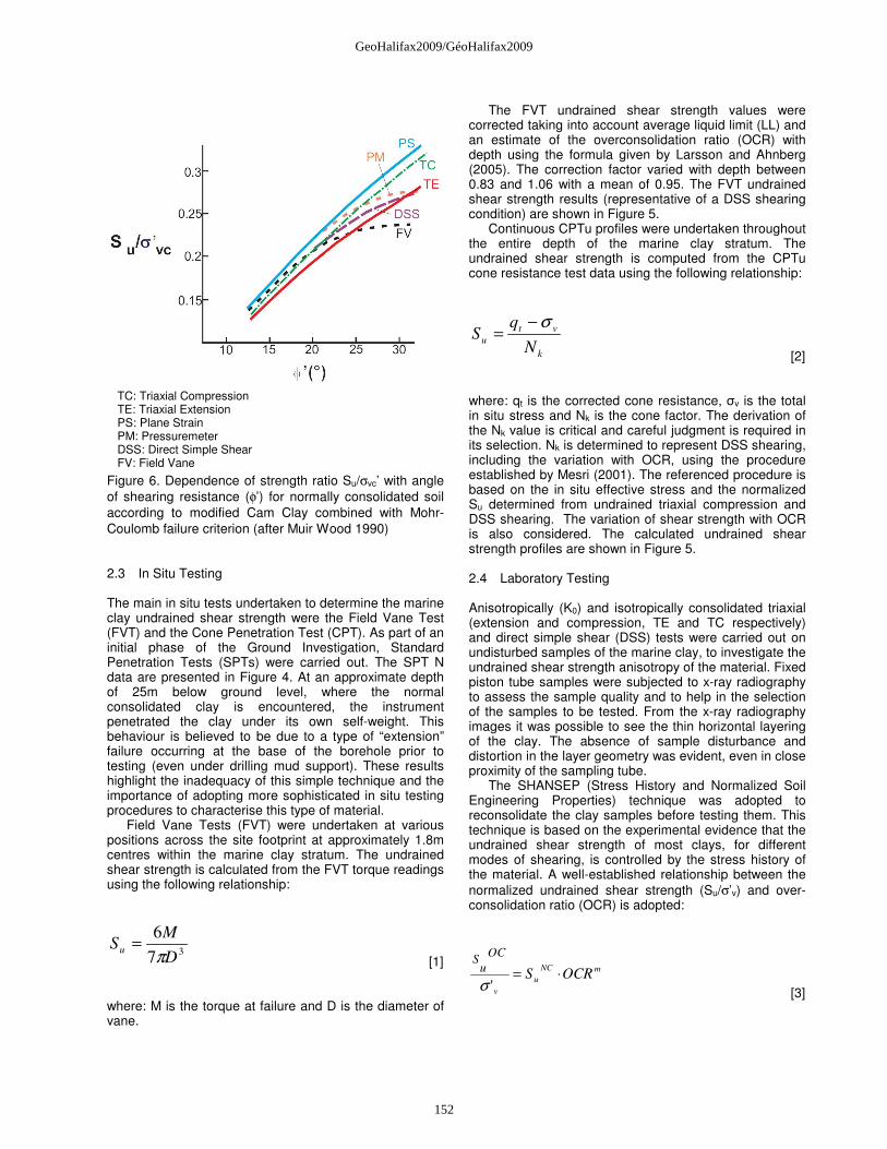
Figure 6. Dependence of strength ratio Su/σvc’ with angle of shearing resistance (φ’) for normally consolidated soil according to modified Cam Clay combined with Mohr-Coulomb failure criterion (after Muir Wood 1990) 2.3 In Situ Testing The main in situ tests undertaken to determine the marine clay undrained shear strength were the Field Vane Test (FVT) and the Cone Penetration Test (CPT). As part of an initial phase of the Ground Investigation, Standard Penetration Tests (SPTs) were carried out. The SPT N data are presented in Figure 4. At an approximate depth of 25m below ground level, where the normal consolidated clay is encountered, the instrument penetrated the clay under its own self-weight. This behaviour is believed to be due to a type of “extension” failure occurring at the base of the borehole prior to testing (even under drilling mud support). These results highlight the inadequacy of this simple technique and the importance of adopting more sophisticated in situ testing procedures to characterise this type of material.
Field Vane Tests (FVT) were undertaken at various positions across the site footprint at approximately 1.8m centres within the marine clay stratum. The undrained shear strength is calculated from the FVT torque readings using the following relationship:
37
6
D
MSu
π=
[1] where: M is the torque at failure and D is the diameter of vane.
The FVT undrained shear strength values were corrected taking into account average liquid limit (LL) and an estimate of the overconsolidation ratio (OCR) with depth using the formula given by Larsson and Ahnberg (2005). The correction factor varied with depth between 0.83 and 1.06 with a mean of 0.95. The FVT undrained shear strength results (representative of a DSS shearing condition) are shown in Figure 5.
Continuous CPTu profiles were undertaken throughout the entire depth of the marine clay stratum. The undrained shear strength is computed from the CPTu cone resistance test data using the following relationship:
k
vt
uN
qS
σ−=
[2] where: qt is the corrected cone resistance, σv is the total in situ stress and Nk is the cone factor. The derivation of the Nk value is critical and careful judgment is required in its selection. Nk is determined to represent DSS shearing, including the variation with OCR, using the procedure established by Mesri (2001). The referenced procedure is based on the in situ effective stress and the normalized Su determined from undrained triaxial compression and DSS shearing. The variation of shear strength with OCR is also considered. The calculated undrained shear strength profiles are shown in Figure 5.
2.4 Laboratory Testing Anisotropically (K0) and isotropically consolidated triaxial (extension and compression, TE and TC respectively) and direct simple shear (DSS) tests were carried out on undisturbed samples of the marine clay, to investigate the undrained shear strength anisotropy of the material. Fixed piston tube samples were subjected to x-ray radiography to assess the sample quality and to help in the selection of the samples to be tested. From the x-ray radiography images it was possible to see the thin horizontal layering of the clay. The absence of sample disturbance and distortion in the layer geometry was evident, even in close proximity of the sampling tube.
The SHANSEP (Stress History and Normalized Soil Engineering Properties) technique was adopted to reconsolidate the clay samples before testing them. This technique is based on the experimental evidence that the undrained shear strength of most clays, for different modes of shearing, is controlled by the stress history of the material. A well-established relationship between the normalized undrained shear strength (Su/σ’v) and over-consolidation ratio (OCR) is adopted:
mNC
u
v
OCRS
OC
uS
⋅='σ [3]
TC: Triaxial Compression TE: Triaxial Extension PS: Plane Strain PM: Pressuremeter DSS: Direct Simple Shear FV: Field Vane
152
GeoHalifax2009/GéoHalifax2009

where: SuOC is the undrained shear strength under
overconsolidated conditions, σ’v is the vertical effective stress, Su
NC is the undrained shear strength under normally consolidated conditions and m is a constant.
The application of the method to stability analyses relies on the accurate evaluation of the stress history (OCR profile) of the clay. The OCR profiling was undertaken by performing a suite of constant rate of strain consolidation (CRSC) tests on undisturbed samples of the marine clay.
The SHANSEP method is based on consolidating the sample to pressure levels well beyond its preconsolidation pressure. The sample is then unloaded to the required OCR and then subjected to shearing (TC, TE or DSS test). By imposing a range of applicable OCRs and subjecting the samples to the different tests it is possible to obtain the Su/σ’v vs. OCR relationship for each mode of shearing.
The initial consolidation stage of the test has the advantage of removing the effects of sample disturbance. The SHANSEP method is considered applicable to fairly uniform deposits of normally consolidated or slightly overconsolidated clays, and it is less appropriate for highly structured clays, weathered crusts, in which often the high OCR is not due to mechanical overconsolidation. For these materials the technique should give conservative strength estimates.
The SHANSEP method was adopted since the classic recompression technique can give unconservative strength estimates for normally consolidated deposits. This effect is due to the reduction in water content, and gain in strength, which is often observed when a clay sample is reconsolidated to the in situ stress. This condition is indicatively shown in Figure 7. Table 1 summarises the best estimate design undrained shear strength values evaluated from the SHANSEP laboratory tests, in terms of normalised undrained shear strength.
Effective Vertical Stress (kPa)
Voi
d R
atio
, e
0.80
10
0.70
0.60
0.50
0.40100 1000
SHANSEP OCR=3[SHEAR SAMPLE]
unloading
sampling
reconsolidation
in situ conditionσ'v=173kPa
in situ preconsolidationpressure = 400kPa
RECOMPRESSION[SHEAR SAMPLE]
Reduction in watercontent, with followinggain in strength
Figure 7. Indicative comparison between SHANSEP and recompression reconsolidation techniques
Table 1. Su/σ'v for range of OCR
Su/σ'v OCR
DSS TC TE
1 0.2 0.27 0.15
1.5 0.27 0.36 0.20
2 0.35 0.47 0.26
4 0.65 0.88 0.49
(DSS: direct simple shear; TC: triaxial compression; TE: triaxial extension) 3 EXCAVATION STABILITY Short term (total stress) excavation stability conditions often govern the design of multi-supported retaining systems for deep excavations in clay. The system stability is considered to be of prime concern with normally consolidated deposits. The assessment of both base and global stability is required for appropriate selection of factors of safety. The most commonly adopted techniques to assess excavation stability are based on the Limit Equilibrium approach and the Finite Element method.
The undrained shear strength anisotropy of clay can significantly affect the stability conditions of geotechnical systems such as embankments, slopes and excavations. In general, different shearing modes related to the principal stress orientation, can be assumed for the various zones surrounding a retaining wall, as shown in Figure 8. Consequently, an appropriate range of strengths should be adopted for each of these zones. In Figure 8 the symbols PSA (Plane Strain Active) and PSP (Plane Strain Passive) indicate that compression and extension plane strain tests are representative of the strength in zones where the shearing of the soil takes place at 45° to the horizontal. Undrained shear strength from DSS (Direct Simple Shear) tests are more representative of zones where the soil is sheared along the horizontal and vertical directions.
Part of the laboratory testing regime included a series of triaxial tests that were carried out on marine clay samples. An approximation is introduced when considering the equivalence between PSA and TC (compression) and PSP and TE (extension) strengths applicable to the zones shown in Figure 8. This assumption is considered appropriate for the marine clay concerned.
153
GeoHalifax2009/GéoHalifax2009
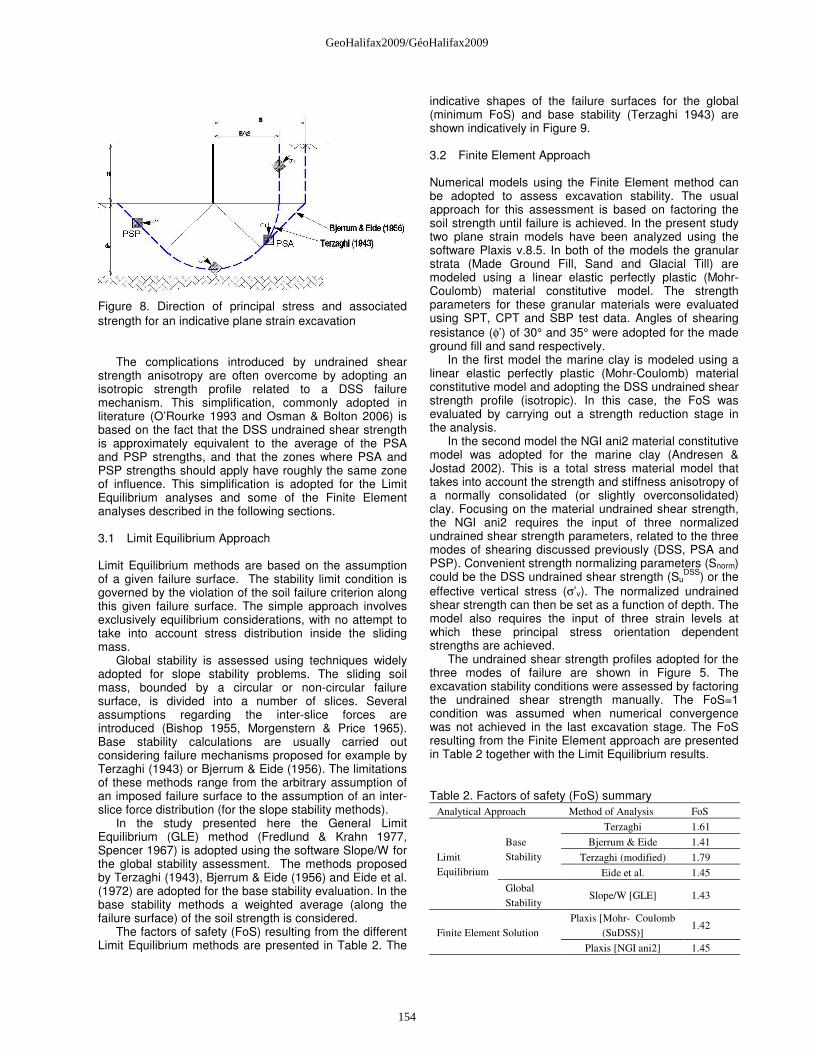
Figure 8. Direction of principal stress and associated strength for an indicative plane strain excavation
The complications introduced by undrained shear strength anisotropy are often overcome by adopting an isotropic strength profile related to a DSS failure mechanism. This simplification, commonly adopted in literature (O’Rourke 1993 and Osman & Bolton 2006) is based on the fact that the DSS undrained shear strength is approximately equivalent to the average of the PSA and PSP strengths, and that the zones where PSA and PSP strengths should apply have roughly the same zone of influence. This simplification is adopted for the Limit Equilibrium analyses and some of the Finite Element analyses described in the following sections.
3.1 Limit Equilibrium Approach Limit Equilibrium methods are based on the assumption of a given failure surface. The stability limit condition is governed by the violation of the soil failure criterion along this given failure surface. The simple approach involves exclusively equilibrium considerations, with no attempt to take into account stress distribution inside the sliding mass.
Global stability is assessed using techniques widely adopted for slope stability problems. The sliding soil mass, bounded by a circular or non-circular failure surface, is divided into a number of slices. Several assumptions regarding the inter-slice forces are introduced (Bishop 1955, Morgenstern & Price 1965). Base stability calculations are usually carried out considering failure mechanisms proposed for example by Terzaghi (1943) or Bjerrum & Eide (1956). The limitations of these methods range from the arbitrary assumption of an imposed failure surface to the assumption of an inter-slice force distribution (for the slope stability methods).
In the study presented here the General Limit Equilibrium (GLE) method (Fredlund & Krahn 1977, Spencer 1967) is adopted using the software Slope/W for the global stability assessment. The methods proposed by Terzaghi (1943), Bjerrum & Eide (1956) and Eide et al. (1972) are adopted for the base stability evaluation. In the base stability methods a weighted average (along the failure surface) of the soil strength is considered.
The factors of safety (FoS) resulting from the different Limit Equilibrium methods are presented in Table 2. The
indicative shapes of the failure surfaces for the global (minimum FoS) and base stability (Terzaghi 1943) are shown indicatively in Figure 9.
3.2 Finite Element Approach Numerical models using the Finite Element method can be adopted to assess excavation stability. The usual approach for this assessment is based on factoring the soil strength until failure is achieved. In the present study two plane strain models have been analyzed using the software Plaxis v.8.5. In both of the models the granular strata (Made Ground Fill, Sand and Glacial Till) are modeled using a linear elastic perfectly plastic (Mohr-Coulomb) material constitutive model. The strength parameters for these granular materials were evaluated using SPT, CPT and SBP test data. Angles of shearing resistance (φ’) of 30° and 35° were adopted for the made ground fill and sand respectively.
In the first model the marine clay is modeled using a linear elastic perfectly plastic (Mohr-Coulomb) material constitutive model and adopting the DSS undrained shear strength profile (isotropic). In this case, the FoS was evaluated by carrying out a strength reduction stage in the analysis.
In the second model the NGI ani2 material constitutive model was adopted for the marine clay (Andresen & Jostad 2002). This is a total stress material model that takes into account the strength and stiffness anisotropy of a normally consolidated (or slightly overconsolidated) clay. Focusing on the material undrained shear strength, the NGI ani2 requires the input of three normalized undrained shear strength parameters, related to the three modes of shearing discussed previously (DSS, PSA and PSP). Convenient strength normalizing parameters (Snorm) could be the DSS undrained shear strength (Su
DSS) or the effective vertical stress (σ’v). The normalized undrained shear strength can then be set as a function of depth. The model also requires the input of three strain levels at which these principal stress orientation dependent strengths are achieved.
The undrained shear strength profiles adopted for the three modes of failure are shown in Figure 5. The excavation stability conditions were assessed by factoring the undrained shear strength manually. The FoS=1 condition was assumed when numerical convergence was not achieved in the last excavation stage. The FoS resulting from the Finite Element approach are presented in Table 2 together with the Limit Equilibrium results.
Table 2. Factors of safety (FoS) summary Analytical Approach Method of Analysis FoS
Terzaghi 1.61
Bjerrum & Eide 1.41
Terzaghi (modified) 1.79
Base
Stability
Eide et al. 1.45
Limit
Equilibrium
Global
Stability Slope/W [GLE] 1.43
Plaxis [Mohr- Coulomb
(SuDSS)] 1.42
Finite Element Solution
Plaxis [NGI ani2] 1.45
154
GeoHalifax2009/GéoHalifax2009

Figure 9. Limit Equilibrium and Finite Element indicative failure mechanism comparison 4 CONCLUSIONS AND DISCUSSION The undrained stability of a 17m deep excavation in marine clay is analysed. The clay is characterized by an overconsolidated crust overlying normally consolidated material.
The authors highlight the need for more advanced in situ and laboratory testing. The SHANSEP technique was adopted for the reconsolidation of the undisturbed samples. A detailed assessment of the stress history of the marine clay was carried out by performing a series of CRSC tests.
The stability assessment is carried out by adopting selected classic Limit Equilibrium methods and by performing simple Finite Element analyses. The different Limit Equilibrium methods show some variability in FoS, ranging from 1.41 using Bjerrum & Eide (1956) to 1.79 using modified Terzaghi (1943) which takes into account the embedded wall length. It is interesting that the more conservative Limit Equilibrium methods (Bjerrum & Eide 1956 and Eide et al. 1972) give FoS in line with the global stability and Finite Element approaches for the excavation concerned. Both of the Terzaghi methods (with and without wall embedment) result in less safe estimates.
The failure surface indicated by the strength reduction procedure is very similar in both of the Finite Element models analysed (modelling the marine clay as a Mohr Coulomb material or using the NGI ani2 material model). An indicative shear strain contour plot at failure is shown in Figure 9 which indicates the failure mode. Indicative slip surfaces related to the base stability and global stability mechanisms are also presented for comparison. The Finite Element failure mode develops along a surface positioned between the base failure and a global failure surfaces.
The FoS obtained in the two Finite Element analyses are similar, 1.42 using Mohr-Coulomb and 1.45 using NGI ani2 material models for the clay. The results demonstrate that, for the case study concerned, a “DSS equivalent” undrained shear strength profile can be adopted for excavation stability assessments using Limit Equilibrium or Finite Element methods. This is due to a combination of two key factors. Firstly, the stress field in the soil mass surrounding the retention system, in terms of principal stress orientation, and secondly, the particular marine clay strength properties (Su/σ'v for different modes of shearing).
ACKNOWLEDGEMENTS The authors would like to extend their gratitude to the Buro Happold project team and would like to acknowledge the support from the wider Ground Engineering discipline. REFERENCES Andresen L. and Jostad H.P. 2002. A constitutive model
for anisotropic and strain-softening clay. Proc. Num. Mod. Geomech. NUMOG VIII, Rome, Italy 2002.
Bishop A.W. 1955. The use of the slip circle in the stability analysis of slopes. Geotechnique.
Bjerrum L. and Eide O. 1956. Stability of strutted excavations in clay. Geotechnique.
Eide O., Aas G. and Josang T. 1972. Special application of cast-in-place walls for tunnels in soft clays. Proc. 5th European Conference on Soil mechanics and foundation Engineering. Madrid, Spain.
Fredlund D.G. and Krahn J. 1977. Comparison of slope stability methods of analysis. Canadian Geotechnical Journal.
Hashash Y.M.A. and Whittle A.J. 1996. Ground movement prediction for deep excavation in soft clay. Journal of Geotechnical Engineering.
Ladd C.C. and De Groot D.J. 2004. Recommended practice for soft ground site characterization. Arthur Casagrande Lecture. Cambridge, MA USA 2003.
R Larsson and H Ahnberg 2005. On the evaluation of undrained shear strength and preconsolidation pressure from common field tests in clay. Canadian Geotechnical Journal
Mesri G. 2001. Undrained shear strength of soft clays from push cone penetration test. Geotechnique.
Morgestern N.R. and Price V.E. 1965. The analysis of the stability of general slip surfaces. Geotechnique.
Muir Wood D. 1990. Soil behaviour and critical state soil mechanics. Cambridge: Cambridge University Press.
NGI-ANI2 Material Model 2005. User defined material model for PLAXIS Version 8.5 - User Manual.
Osman A.S. and Bolton M.D. 2006. Ground movement predictions for braced excavations in undrained clay. Journal of Geotechnical and Geoenvironmental Engineering.
O'Rourke T.D. 1993. Base stability and ground movement prediction for excavations in soft clay. Retaining Structures. London: Thomas Telford.
Santagata M. and Germaine J.T. 2005. Effect of OCR on sampling disturbance of cohesive soils and evaluation of laboratory reconsolidation procedures. Canadian Geotechnical Journal.
Seah T.H. and Lai K.C. 2003. Strength and deformation behavior of soft Bangkok clay. Geotechnical Testing Journal.
Spencer E. 1967. A method of analysis of the stability of embankments assuming parallel interslice forces. Geotechnique.
Su S.F., Liao H.J., Lin Y.H. 1998. Base stability of deep excavation in anisotropic soft clay. Journal of Geotechnical and Geoenvironmental Engineering.
155
GeoHalifax2009/GéoHalifax2009
Terzaghi K. 1943. Theoretical soil mechanics. New York: Wiley.
Ukritchon B., Whittle A.J., Sloan S.W. 2003. Undrained stability of braced excavation in clay. Journal of Geotechnical and Geoenvironmental Engineering.
156
GeoHalifax2009/GéoHalifax2009