Short communication Characteristics and performance of ...
5
Journal of Power Sources 162 (2006) 1416–1420 Short communication Characteristics and performance of 10 kW class all-vanadium redox-flow battery stack Ping Zhao ∗ , Huamin Zhang ∗∗ , Hantao Zhou, Jian Chen, Sujun Gao, Baolian Yi PEMFC Key Materials & Technology Laboratory, Dalian Institute of Chemical Physics (DICP), Chinese Academy of Sciences, Dalian, Liaoning 116023, PR China Received 25 July 2006; accepted 10 August 2006 Available online 20 September 2006 Abstract A kW class all-vanadium redox-flow battery (VRB) stack, which was composed of 14 cells each with an electrode geometric surface area of 875 cm 2 , with an average output power of 1.14 kW, at the charge–discharge current density of 70 mA cm −2 , was successfully assembled by filter press type. Then, a 10 kW class VRB stack was manufactured with a configuration of 4 × 2 (serial × parallel) of the improved aforementioned kW class stack modules, which produced a direct output of 10.05 kW (current density 85 mA cm −2 ). The energy efficiency of more than 80%, at an average output power of 10.05kW, for the 10kW class VRB stack was achieved, indicating VRB is a promising high efficiency technology for electric storage. © 2006 Elsevier B.V. All rights reserved. Keywords: Vanadium redox-flow battery; Energy storage; Cell stack 1. Introduction For a sustainable and clean future, considerations are increas- ingly given to the limitless renewable energy such as solar, wind, wave, etc. It can be anticipated that renewable power sources will make increasing contributions to electricity generation in the decades ahead [1]. Renewables, however, possess the vari- able and intermittent nature of their output, so there is often the problem of matching the supply to meet the demand [1]. To make better use of the electricity generated by renewables, research, development and application of economical and effi- cient energy-storage systems become indispensable and urgent [1]. Of all the new energy storage technologies currently under development around the world, the redox flow battery (RFB) appears to offer great promise as a low cost, high-efficiency large-scale energy storage system [2–8] and has been reviewed recently [9]. All-vanadium redox flow battery (VRB) proposed by Skyllas- Kazacos et al. [4–6] holds all the merits of other RFBs ∗ Corresponding author. Tel.: +86 411 84379535; fax: +86 411 84665057. ∗∗ Co-corresponding author. E-mail addresses: [email protected] (P. Zhao), [email protected] (H. Zhang). [2,3]. Moreover, because of using only vanadium species for both halves of the cell, the problem of electrolytes cross- contamination through battery separator was overcome [4–6]. Based on these attractive features, more and more attentions have been paid to VRB recently [7–18]. In 1991, a VRB cell stack was fabricated by Skyllas-Kazacos et al., which produced an average power output of 1.1 kW at the discharge current density of 60 mA cm −2 with an energy efficiency of 77.7% [5]. Different kinds of RFBs have been studied at our research group since 1989 [3,17–26]. In this work, we focused on the characteristics and performance of the VRB cell stack recently developed in our lab. 2. Principle of VRB As shown in Fig. 1, the VRB has two electrolyte loops both containing vanadium in sulfuric acid medium, but in different valence states which may be oxidized/reduced at the electrodes. The vanadium redox pairs are V 2+ /V 3+ and V 4+ /V 5+ for neg- ative and positive halves of the cell, respectively. The electri- cal balance is achieved by the transport of hydrogen ions in the electrolytes across the membrane during operation of the cell. 0378-7753/$ – see front matter © 2006 Elsevier B.V. All rights reserved. doi:10.1016/j.jpowsour.2006.08.016
Transcript of Short communication Characteristics and performance of ...

A
8pcae©
K
1
iwwtatTrc[dalr
K
(
0d
Journal of Power Sources 162 (2006) 1416–1420
Short communication
Characteristics and performance of 10 kW classall-vanadium redox-flow battery stack
Ping Zhao ∗, Huamin Zhang ∗∗, Hantao Zhou, Jian Chen, Sujun Gao, Baolian YiPEMFC Key Materials & Technology Laboratory, Dalian Institute of Chemical Physics (DICP),
Chinese Academy of Sciences, Dalian, Liaoning 116023, PR China
Received 25 July 2006; accepted 10 August 2006Available online 20 September 2006
bstract
A kW class all-vanadium redox-flow battery (VRB) stack, which was composed of 14 cells each with an electrode geometric surface area of75 cm2, with an average output power of 1.14 kW, at the charge–discharge current density of 70 mA cm−2, was successfully assembled by filter
ress type. Then, a 10 kW class VRB stack was manufactured with a configuration of 4 × 2 (serial × parallel) of the improved aforementioned kWlass stack modules, which produced a direct output of 10.05 kW (current density 85 mA cm−2). The energy efficiency of more than 80%, at anverage output power of 10.05 kW, for the 10 kW class VRB stack was achieved, indicating VRB is a promising high efficiency technology forlectric storage.2006 Elsevier B.V. All rights reserved.
[bcBh
ete
gcd
2
eywords: Vanadium redox-flow battery; Energy storage; Cell stack
. Introduction
For a sustainable and clean future, considerations are increas-ngly given to the limitless renewable energy such as solar, wind,ave, etc. It can be anticipated that renewable power sourcesill make increasing contributions to electricity generation in
he decades ahead [1]. Renewables, however, possess the vari-ble and intermittent nature of their output, so there is oftenhe problem of matching the supply to meet the demand [1].o make better use of the electricity generated by renewables,esearch, development and application of economical and effi-ient energy-storage systems become indispensable and urgent1]. Of all the new energy storage technologies currently underevelopment around the world, the redox flow battery (RFB)ppears to offer great promise as a low cost, high-efficiencyarge-scale energy storage system [2–8] and has been reviewed
ecently [9].All-vanadium redox flow battery (VRB) proposed by Skyllas-azacos et al. [4–6] holds all the merits of other RFBs
∗ Corresponding author. Tel.: +86 411 84379535; fax: +86 411 84665057.∗∗ Co-corresponding author.
E-mail addresses: [email protected] (P. Zhao), [email protected]. Zhang).
cvTactc
378-7753/$ – see front matter © 2006 Elsevier B.V. All rights reserved.oi:10.1016/j.jpowsour.2006.08.016
2,3]. Moreover, because of using only vanadium species foroth halves of the cell, the problem of electrolytes cross-ontamination through battery separator was overcome [4–6].ased on these attractive features, more and more attentionsave been paid to VRB recently [7–18].
In 1991, a VRB cell stack was fabricated by Skyllas-Kazacost al., which produced an average power output of 1.1 kW athe discharge current density of 60 mA cm−2 with an energyfficiency of 77.7% [5].
Different kinds of RFBs have been studied at our researchroup since 1989 [3,17–26]. In this work, we focused on theharacteristics and performance of the VRB cell stack recentlyeveloped in our lab.
. Principle of VRB
As shown in Fig. 1, the VRB has two electrolyte loops bothontaining vanadium in sulfuric acid medium, but in differentalence states which may be oxidized/reduced at the electrodes.
he vanadium redox pairs are V2+/V3+ and V4+/V5+ for neg-tive and positive halves of the cell, respectively. The electri-al balance is achieved by the transport of hydrogen ions inhe electrolytes across the membrane during operation of theell.
P. Zhao et al. / Journal of Power Sources 162 (2006) 1416–1420 1417
Fig. 1. Operation principle of the VRB flow single cell. Positive electrode side:
V4+ − echarge�
dischargeV5+; negative electrode side: V3+ + e
charge�
dischargeV2+. Photo cour-
tesy of Sumitomo Electric Industries Ltd. (SEI). Copyright 2001.
F
3
c
wp
IwTc
Table 1Specifications for 1 kW class VRB stack
Area of felt electrode 875 cm2
Number of cells 14Membrane material Nafion (Du Pont)Bipolar electrode material Graphite plateMaterial of electrode frame PVC (polyvinyl chloride)Material of end plate Aluminum alloyStack dimensions (L × W × H) 440 mm × 340 mm × 200 mmElectrolyte 1.5 M VOSO4 + 3 M H2SO4
Electrolyte volume per half-cell/l 7.4Operate temperature Ambient
Fo
(tAr
4
4
rbttthrough the membrane, and hence the rate of self-discharge of
TP
C
12581
ig. 2. Photo of 14-cell 1 kW class VRB cell stack. Single cell index: 1 → 14.
. Experimental
The 1 kW class VRB cell stack, as shown in Fig. 2, wasonstructed according to the specifications given in Table 1.
The carbon felt (Shanghai XinXing Carbon Co. Ltd., China)as chemically treated before being used as the negative andositive electrode materials for VRB.
The charge–discharge cycle test was conducted by Arbinnstrument (Model BT 2000, Arbin Instruments Corp., USA),
hich ran under the control of presetting schedules given by us.he stack coulombic efficiency (CE) is defined as the dischargeapacity (Ah) divided by the charge capacity, energy efficiencytbd
able 2erformance of 1 kW class VRB stack
ycle index Charge–dischargecurrent (A)
Current density(mA cm−2)
Average outpvoltage (V)
st 74.38 85 18.19–4th 34.97 40 19.10–7th 43.72 50 19.07–9th 52.46 60 18.880–11th 61.23 70 18.68
ig. 3. Charge–discharge curves for 1 kW class VRB cell stack at current densityf (a) 70 mA cm−2, (b) 60 mA cm−2, and (c) 50 mA cm−2.
EE) as discharge energy (Wh) divided by charge energy. Thenhe voltage efficiency (VE) can be calculated from VE = EE/CE.ll the data of the charge/discharge capacity and energy were
ecorded by Arbin instrument automatically.
. Results and discussion
.1. Performance of 14-cell 1 kW VRB stack
The CE of the stack increases with the increasing of the cur-ent density, as can be seen from Table 2. This phenomenon coulde attributed to that with the increasing of the current density,he charge and discharge cycle time become shorter (see Fig. 3),hus lowering the diffusion of the electrochemical active species
he cell. However, the overall polarization of the stack couldecome larger unavoidably, with the increasing of the currentensity, thus a decreasing of VE can be expected. The change
ut Average outputpower (kW)
CE (%) VE (%) EE (%)
1.353 – – –0.668 82.62 93.64 77.370.834 84.00 92.49 77.730.991 85.90 91.10 78.251.144 87.12 89.68 78.12

1418 P. Zhao et al. / Journal of Power Sources 162 (2006) 1416–1420
e in t
oFetaomhcatoo
4
peccwaotc
Taci
4s
1oc
mihersasp
Fig. 4. Distribution of voltag
f EE is subjected to that of CE and VE, since EE = CE × VE.rom Table 2, it can be seen that the coulombic, voltage andnergy efficiency was up to 85.9%, 91.1% and 78.3%, respec-ively, at a current density of 60 mA cm−2, and a maximumverage output power of 1.35 kW at a discharge current densityf 85 mA cm−2 was determined. Comparison with the perfor-ance data reported in Ref. [5], the stack in this work possesses
igher VE and EE, but a lower CE at the same charge–dischargeurrent density, indicating that the internal resistance (IR) dropnd electrochemical polarization of electrode reactions duringhe operation of the stack are lower. However, the lower CEf the stack implied that the stack at this stage needs furtherptimizing [27].
.2. Voltage distribution in the 14-cell 1 kW VRB stack
In a RFB cell stack assembled by filter press type, uniformerformance of each unit cell is of great importance. Fig. 4xhibits the voltage distribution of the stack at various state-of-harge (SOC), state-of-discharge (SOD) and charge–dischargeurrent densities, revealing that voltage distribution in the stackas extraordinarily uniform, especially at lower SOC or SOD
nd current density, which indicates fairly uniform distributionf the IR, the reactant electrolytes from the electrolyte inlet tohe outlet and activation polarization of the electrodes of unitells in the stack. The cell index was designated as in Fig. 2.
a
oo
Fig. 5. Photos of 10 kW class VRB cell stack composed of eight 1 kW
he 14-cell 1 kW VRB stack.
he standard deviation of the unit cell voltages was 2.14, 5.20,nd 6.84 mV at the SOC of 10%, 80% and SOD of 80% and aharge–discharge current density of 60 mA cm−2, as presentedn Fig. 4(b), respectively.
.3. Fabrication and performance of 10 kW class VRB celltack
Based on the results given by 14-cell 1 kW class VRB stack, a0 kW VRB stack system was constructed with a configurationf 4 × 2 (serial × parallel) of the improved aforementioned kWlass stack modules, as presented in Fig. 5.
Comparing the performance of 10 kW class VRB stack sum-arized in Table 3 with that of 1 kW class stack in Table 2,
t is clear that the CE of 10 kW class stack in Table 3 is muchigher than that of 1 kW stack in Table 2, indicating the measuresmployed to modify the 1 kW class VRB stack are effective toeduce the shunt current [26,27], hence, increase the CE of thetack. A maximum in the overall EE of up to 82.4% is observedt a current density of 50 mA cm−2. The CE, VE and EE of thetack is 92.9%, 86.5% and 80.4%, respectively, and the outputower is 10.05 kW at a discharge current density of 85 mA cm−2,
s shown in Table 3.In order to study the influence of module configuration onutput power, the stack power–discharge current density curvesf VRB stack with configurations of 4S × 2P (serial × parallel)
stack modules with a configuration of 4 × 2 (serial × parallel).

P. Zhao et al. / Journal of Power Sources 162 (2006) 1416–1420 1419
Table 3Performance of 10 kW class VRB cell stack
Charge–discharge current (A) Charge–discharge current density (mA cm−2) Average output power (kW) CE (%) VE (%) EE (%)
C105–D149 C60–D85 10.05 92.94 86.54 80.43C105–D140 C60–D80 9.53 92.03 87.19 80.24122.5 70 8.41 93.03 87.06 80.99105 60 7.23 91.77 88.20 80.9487.5 50 6.14 90.95 90.54 82.3570 40 4.95 89.02 92.03 81.93
Fw
aistocuoctsl
s
vtucuv8
ais
ig. 6. Power–current density curves for eight-module 10 kW class VRB stackith different configurations of kW class stack modules.
nd 8S (serial) were determined, respectively, and illustratedn Fig. 6. The little difference in output power of 10 kW VRBtack with various configurations, as shown in Fig. 6, tells ushat the module configuration has nearly no influence on theutput power of the stack, indicating the scale-up of VRB stackan be easily by serial and/or parallel connection of stack mod-les to increase the output voltage and/or current, hence theutput power. The output power of 11.3 kW (power density isa. 0.13 W cm−2) is achieved, as can be seen from Fig. 6, athe current density of 90 mA cm−2. The true peak power of this
tack has not yet been established, however, due to equipmentimitations.Fig. 7 shows the voltage distribution of the 10 kW class VRBtack at various SOC, SOD and current densities, revealing that
aisr
Fig. 7. Distribution of voltage in the eight-module 10
Fig. 8. Charge–discharge cyclic curves of VRB stack.
oltage distribution in the stack was fairly uniform, and a lit-le influence of scale-up from 1 kW stack to 10 kW one on theniform distribution of the internal resistance (IR), the electro-hemically active solutions and polarization of the electrodes ofnit cells in the stack. The standard deviation of the unit celloltages was 5.78, 8.94, and 8.12 mV at the SOC of 10% and0% and SOD of 80% in Fig. 7(a), respectively.
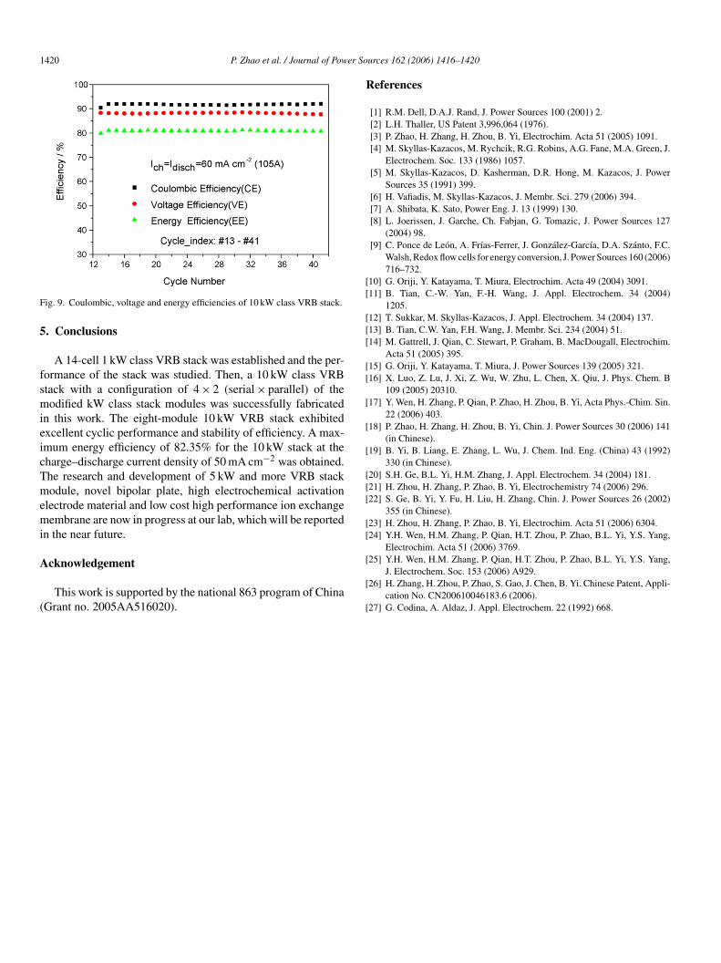
A series of uninterrupted charge–discharge curves obtainedt the current density of 60 mA cm−2 is given in Fig. 8, whichs fairly smooth, revealing that the cyclic performance of thetack is excellent. Fig. 9 shows a plot of coulombic, voltage
nd energy efficiency as a function of cycle number correspond-ng to Fig. 8. The average values of CE, VE and EE of thetack illustrated in Fig. 9 are about 91.8%, 88.2% and 80.9%,espectively.kW class VRB stack at various current density.
1420 P. Zhao et al. / Journal of Power So
F
5
fsmieicTmemi
A
(
R
[[
[[[
[[
[
[
[
[[[
[[
ig. 9. Coulombic, voltage and energy efficiencies of 10 kW class VRB stack.
. Conclusions
A 14-cell 1 kW class VRB stack was established and the per-ormance of the stack was studied. Then, a 10 kW class VRBtack with a configuration of 4 × 2 (serial × parallel) of theodified kW class stack modules was successfully fabricated
n this work. The eight-module 10 kW VRB stack exhibitedxcellent cyclic performance and stability of efficiency. A max-mum energy efficiency of 82.35% for the 10 kW stack at theharge–discharge current density of 50 mA cm−2 was obtained.he research and development of 5 kW and more VRB stackodule, novel bipolar plate, high electrochemical activation
lectrode material and low cost high performance ion exchangeembrane are now in progress at our lab, which will be reported
n the near future.
cknowledgement
This work is supported by the national 863 program of ChinaGrant no. 2005AA516020).
[
[
[
urces 162 (2006) 1416–1420
eferences
[1] R.M. Dell, D.A.J. Rand, J. Power Sources 100 (2001) 2.[2] L.H. Thaller, US Patent 3,996,064 (1976).[3] P. Zhao, H. Zhang, H. Zhou, B. Yi, Electrochim. Acta 51 (2005) 1091.[4] M. Skyllas-Kazacos, M. Rychcik, R.G. Robins, A.G. Fane, M.A. Green, J.
Electrochem. Soc. 133 (1986) 1057.[5] M. Skyllas-Kazacos, D. Kasherman, D.R. Hong, M. Kazacos, J. Power
Sources 35 (1991) 399.[6] H. Vafiadis, M. Skyllas-Kazacos, J. Membr. Sci. 279 (2006) 394.[7] A. Shibata, K. Sato, Power Eng. J. 13 (1999) 130.[8] L. Joerissen, J. Garche, Ch. Fabjan, G. Tomazic, J. Power Sources 127
(2004) 98.[9] C. Ponce de Leon, A. Frıas-Ferrer, J. Gonzalez-Garcıa, D.A. Szanto, F.C.
Walsh, Redox flow cells for energy conversion, J. Power Sources 160 (2006)716–732.
10] G. Oriji, Y. Katayama, T. Miura, Electrochim. Acta 49 (2004) 3091.11] B. Tian, C.-W. Yan, F.-H. Wang, J. Appl. Electrochem. 34 (2004)
1205.12] T. Sukkar, M. Skyllas-Kazacos, J. Appl. Electrochem. 34 (2004) 137.13] B. Tian, C.W. Yan, F.H. Wang, J. Membr. Sci. 234 (2004) 51.14] M. Gattrell, J. Qian, C. Stewart, P. Graham, B. MacDougall, Electrochim.
Acta 51 (2005) 395.15] G. Oriji, Y. Katayama, T. Miura, J. Power Sources 139 (2005) 321.16] X. Luo, Z. Lu, J. Xi, Z. Wu, W. Zhu, L. Chen, X. Qiu, J. Phys. Chem. B
109 (2005) 20310.17] Y. Wen, H. Zhang, P. Qian, P. Zhao, H. Zhou, B. Yi, Acta Phys.-Chim. Sin.
22 (2006) 403.18] P. Zhao, H. Zhang, H. Zhou, B. Yi, Chin. J. Power Sources 30 (2006) 141
(in Chinese).19] B. Yi, B. Liang, E. Zhang, L. Wu, J. Chem. Ind. Eng. (China) 43 (1992)
330 (in Chinese).20] S.H. Ge, B.L. Yi, H.M. Zhang, J. Appl. Electrochem. 34 (2004) 181.21] H. Zhou, H. Zhang, P. Zhao, B. Yi, Electrochemistry 74 (2006) 296.22] S. Ge, B. Yi, Y. Fu, H. Liu, H. Zhang, Chin. J. Power Sources 26 (2002)
355 (in Chinese).23] H. Zhou, H. Zhang, P. Zhao, B. Yi, Electrochim. Acta 51 (2006) 6304.24] Y.H. Wen, H.M. Zhang, P. Qian, H.T. Zhou, P. Zhao, B.L. Yi, Y.S. Yang,
Electrochim. Acta 51 (2006) 3769.
25] Y.H. Wen, H.M. Zhang, P. Qian, H.T. Zhou, P. Zhao, B.L. Yi, Y.S. Yang,J. Electrochem. Soc. 153 (2006) A929.26] H. Zhang, H. Zhou, P. Zhao, S. Gao, J. Chen, B. Yi. Chinese Patent, Appli-
cation No. CN200610046183.6 (2006).27] G. Codina, A. Aldaz, J. Appl. Electrochem. 22 (1992) 668.