SHOP MANUAL - Vintage Sno S ERIES SHOP MANUAL SPEC ... Ignition System ... timing mark on the...
20
SHOP MANUAL 292 cc. ENGINE KT-150 SERIES KAWASAKI MOTORS CORP. ENGINE DIVISION PRINTED JANUARY 1, 1970
Transcript of SHOP MANUAL - Vintage Sno S ERIES SHOP MANUAL SPEC ... Ignition System ... timing mark on the...

SHOP MANUAL
292 cc. ENGINE KT-150 SERIES
KAWASAKI MOTORS CORP.
ENGINE DIVISION
PRINTED JANUARY 1, 1970

KT- 150 S ERIES SHOP MANUAL
SPEC! FICATIONS
Section 1 - LUBRICATION .. . . .. . ... . .. . ..... ... page 5
Section 2 - COMPLETE ENGINE DISASSEMBLY . . . pag e 6
Section 3 - CRANKSHAFT REPAIR . . . . . . . . . . . . . . page 8
Section 4 - TOP END REPAIR . . . . .. . . .. . .. .. ... page 10
Section 5 - IGNITION TIMING .... . . . . . .... . .... page 13
Section 6 - RECOIL STARTER REPAIR ..... . .... . page 15
Section 7 - ISOMETRIC INFORMATION .. ... . . . . page 18
3

s E I 10 s
Kawasaki KT150-292
Typt!
Burt' x Stroke
Displacement
Compression Ratio
Veight
C. 1inder
J .ubrication
Spt.rk Plug
Starting S:- stem
Ignition System
Ignition Timing
Cylinder Head Bolts
Crankcase Bolls
Fl~·whecl Kuts
Single cvlinut•J·, l\\o-<:yclc , piston valve
2 .92 inches x 2. G8 inchel' (?-! mm x 68 mm)
17 .~ cu. in . (292 cc)
7.4:1
4b.5 lbs . without carburetor or muffle1
Aluminum Allo\ wilh cast iron slcc\'e
Oi I rr ixed with ga!'lolinc, 2U lu 1 t·atio
XGK AG or Ai or cqui\'alent
Recoil \\ith emergcnc\ rope pull!~}
Fl) wheel magneto
10° BTDC for slat•lin~ :Httomatlcally advancmg to 25• BTDC during upel'ation
l 6 ft. lbs.
13 ft. lb~.
fi6 ft. Jbs.
RN•oil Startc r Mounting Bolt» 1 :i ft. lbs .
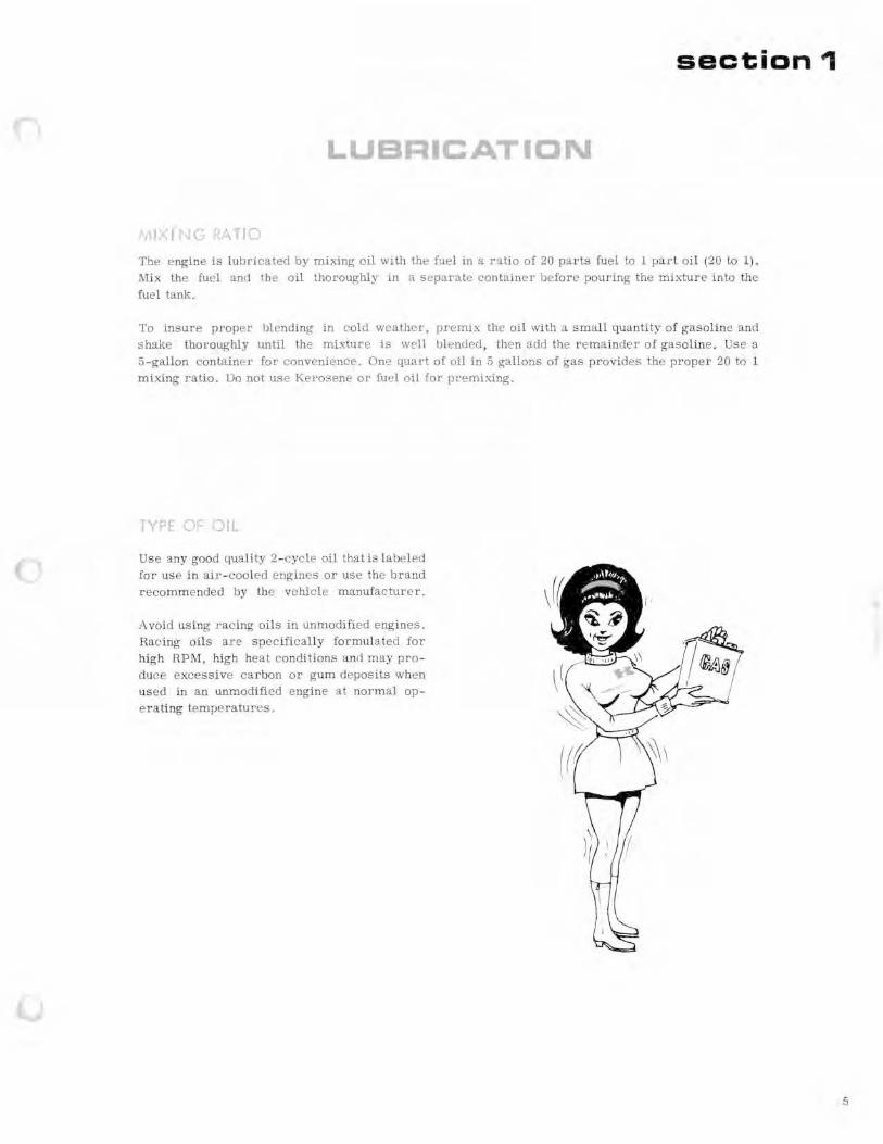
section 1
L B I
The en~ine is lubricated by mixing oil with the fue l in a ratio of 20 parts fuel to 1 part oil (20 to 1). Mix the fuel and the oil thoroughl.v in a separate conhtiner before pouring the mhi:ure into the fuel tank.
To insure proper blending in cold wenther, premix the oil with a. small quantity of gasoline and s hake thoroughly until the mixture is wc:>ll IJlended, then acid the eemainder o f gasoline . Use a 5 -gallon c:onW.int:r for convenience. One quart of oil in 5 gallons of gas provides the proper 20 to 1 mixing ratio. Do not use Kel'osene: or fuel oil for premixing.
E ll
Use any good quality 2- cycle oil that is labeled for use in air-c.:ooled engines or use the brand recomme nded by the vehic le manufacturer.
i\ void using racing oils in unmodified engines . Racing oils are specifically formulated for high RPM, high heat conditions and may produce excessive carbon or gum deposits when used in an unmodified engine at normal operating tempe ratures.
5
6
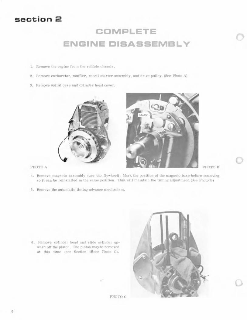
section 2
COMPLETE
ENGINE DISASSEMBL V
l. Remove the engine fr0m the vehicle chassis.
2. Remove carl>uretor , muffler, recoil starter assembly, and dri vt- pulley. (St•t• Photo A)
3. Remove spiral case and cylinder head cover .
P HOTO A PHOTO B
4. Remove magneto assembly (use the flywheel) . .:\lark the position of the magneto base before removing so i t can l>e reinstalled in the same position. This will maintain the timing adjustment. (See Photo B)
5. Remove the automatic timing advance mechanism.
6. He move cylinder head and slide cylinder upward off the piston. The piston maybe removed at this time (see Section -t)fsee Photo C).
PHOTO C

7. Remove the six crankcase l>olts and separate the cases. Hold one-half of the case while tapping the end of the crankshaft with a plastic hammer. ~ever use a steel hammer on the crankshaft. (See Photo D-E)
PHOTO D ENGINE REASSEMBLY
PHOTO E
The engine can be reassembled by reversmg the above procedure. Note the following items:
1. Pack the oil seal lips with bearing grease before reassembly.
2. Check the end play in the crankshaft and use shims to establish proper clearance. Refer to Section 3 of this manual (crankshaft repair).
3. Check the ignition timing and readjust if necessary.
4. Two of the crankcase bolts are 9 mm longer than the other four. Be sure the two are in their proper locations before tightening. Torque all 6 bolts to 13 ft. lbs. using a criss-cross tightening pattern. (Sec Photo F)
PHOTO F
7
8
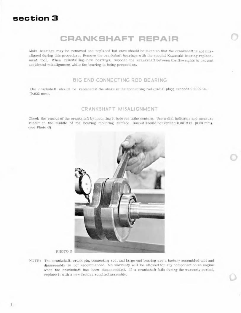
section 3
CRANKSHAFT REPAIR
:.\lain bearings may be r emoved and replaced but care should be taken so that the crankshaft is not misa ligned during this procedure . Remove the crankshaft bearings with the special Kawasaki bearing replacement tool. When reinstalling new bearings, support the crankshaft between the flyweights to prevent accidental misalignment while the bearing is being pressed on .
BIG END CONNECTING ROD BEARING
The crankshaft should be replaced if the shake in the connecting rod (radial play) exceeds 0 .0009 in . (0.023 mm).
CRANKSHAFT MISALIGNMENT
Check the runout of the crankshaft by mounting it between lathe centers. Use a dial indicator and measure runout in the middle of the bearing mounting surface. Runout should not exceed 0 .0012 in. (0 .03 mm). (See Photo G)
PHOTOG
NOTE: The crankshaft, crank pin, connecting rod, and large end bearing are a factory assembled unit and disassembly is not recommended . No warranty will be allowed for any component on an engine when the crankshaft has been disassembled. If a crankshaft fails during the warranty period, replace it with a new factory supplied assembly.

END PLAY
The proper crankshaft end play can be established by following these steps:
1. Install the output end of the crankshaft into the output side of the crankcase. See figure 1.
2. Measure distance B (the distance from the crankcase gasket surface with the gasket removed to the inside bearing mounting surface of the crankshaft flyweight).
3. :'>'Ieasure distance A (the distance from the inside mounting surface of the bearing to the crankcase gasket surface, gasket removed) .
4. Subtract distance B from A and refer to the chart for the proper s him .
SHIM CHART Difference B Subtracted from A Shim No. Shim No. Parts No.
-0 .0070- -0 . 0009 inch (-0. 2 - -0.01 mm) None 1 318401- 3231- 00
0 - 0 . 0038 ( 0 - 0 . 09 ) 4 2 318401-3232-00
0.0039- 0. 0078 ( 0. 10- 0.19 ) 1 3 318401-3233-00
0.0079- 0. 0118 ( 0. 20 - 0 . 29 ) 1 + 4 4 318401- 3234- 00
0. 0119- 0. 0158 ( 0.30- 0. 39) ) 2
0. 0159- 0. 0198 ( 0. 40 - 0.49 ) 2+4
0. 0199 - 0. 0238 ( 0. 50- 0. 59 ) 3
0.0239- 0. 0278 ( 0.60 - 0 . 69 ) 3 + 4
0 . 027!) - 0 . 0318 ( 0. 70- 0. 79 ) 1 + 3
Fig. 1
CRANKSHAFT
MAGNET SIDE
9

section 4
10
TOP END REPAIR
The cylinder and piston can normally be serviced without removing the engine from the vehicle chassis .
1. Remove the exhaust pipe.
2. Remove the cylinder head and cylinder. Stuff a shop cloth into the crankcase opening around the connecting rod· to prevent foreign objects from falling in the crankcase . (Sec Photo H)
PHOTO H
3. Remove the pis ton pin c irclip and use the Kawasaki Universal Pis ton Pin Puller to remove the pis ton pin. Remove the piston and small end needle bearing. (See Photo I)
PHOTO I
4. T he tension in the rings is high but they can easily be r emoved with a l ight cord as illustrated or with a ring removing tool. (See Photo J)
PHOTO J
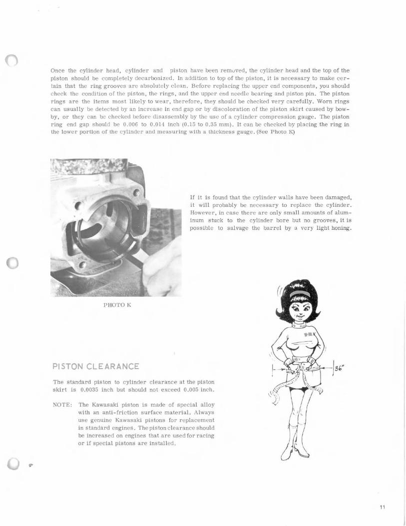
Once the cylinder head, cylinder and piston have been removed, the cylinder head and the top of the piston should be completely decarbonized. In addition to top of the piston, it is necessary to make certain that the ring grooves are absolutely clean. Before replacing the upper end components, you should eheck the condition of the piston, the rings, and the upper end needle bearing and piston pin. The piston rings are the items most likely to wear, therefore, they should be checked very carefully. Worn rings can usually be detected by an increase in end gap or by discoloration of the piston skirt caused by bowby, or they can be checked before disassembly by the use of a cylinder compression gauge. The piston ring end gap should be 0.006 to 0.014 inch (0.15 to 0.35 mm). It can be checked by placing the ring in the lower portion of the cylinder and measuring with a thickness gauge. (Sec Photo K)
PHOTO K
PISTON CLEARANCE
If it is found that the cylinder walls have been damaged, it will probably be necessary to replace the cylinder. However, in case there are only small amounts of aluminum stuck to the cylinder bore but no grooves, it is possible to salvage the barrel by a very light honing.
The standard piston to cylinder clearance at the piston skirt is 0.0035 inch but should not exceed 0.005 inch.
NOTE: The Kawasaki piston is made of special alloy with an anti-friction surface material. Always use genuine Kawasaki pistons for replacement in standard engines . The piston clearance should be increased on engines that are used for racing or if special pistons are installed.
11
12
REASSEMBLING THE TOP END
Reassemble the top end by r eversing the disassembly procedure . Observe the following notes when reassembling. :\lake sure the gasket surfaces are clean and lubricate all parts with 2-cycle oil as they are assembled to protect them when the engine is first started .
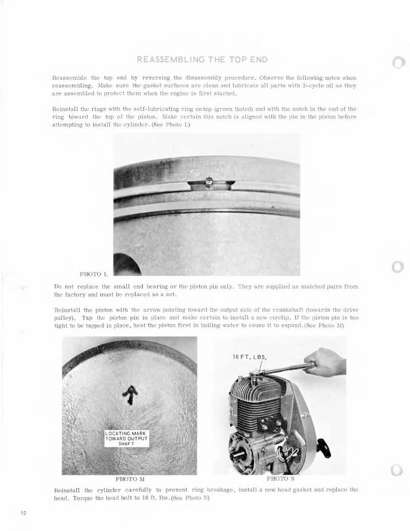
Re ins tall the r ings with the self- lubricating ring on top (green tinted) and with the notch in the end of the ring toward the top of the piston . :\lake certain this notch is aligned with the pin in the piston before attempting to install the cylinder . (Sec Photo L)
PHOTO L
Do not r eplace the small e nd bearing or the piston pin only. They are supplied as matched pairs from the facto ry and must be r eplaced as a set.
Reinstall the piston with the arrow pointing toward the output side of the crankshaft (towards the drive pulley). Tap the piston pin in place and make certain to install a new circlip . If the piston pin is too tight to be tapped in place , hea t the piston first in boiling water to cause it to expanci . (See Photo :\I)
P HOTO l\1 PHOTON
Reinstall the cylinder carefully to prevent ring breakage, install a new head gasket and replace the head. Torque the head bolt to 16 ft. lbs. (See Photo N)

section 5
IGNITION AND ELECTRICAL
IGNITION TIMING ADJUSTMENT To check or adjust the ignition timing, r emove the recoil starter assembly and connect a timing buzzer or continuity tester to the black wire coming out of the engine. If the black wire is connected to the ignition switch, turn the switch to the OJ.\ position. Connect the other test lead to any grounded metal part of the engine . (See Photo 0)
PHOTO 0
The timing should be set so that the breaker points separate when inspection hole "F" lines up with the timing mark on the c rankcase . The timing buzzer will change tone when the points separate. It may be necessary to illuminate the timing mark on the crankcase by shining a flash light on it from carburetor side of the engine , directing the light towards the back side of the cooling fan . Inspection hole "F" is the stationary timing mark (100 BTDC) and hole "T" indicates top dead center. The timing is automatically advanced to 250 BTDC at about 1800 RP.:\1. (See Photo P)
PHOTO P
13

14
The igni tion timing can usually be adjusted by a slight change in the point gap which can be adjusted by removing the recoil starter pulley and the inspection cove r . (See Photo Q)
The breaker point gap should be between 0.012 and 0.016 inch (0 .3 and 0.4 mm). If the timing adjustment cannot be made within these point adjustment limits , it will be necessary to remove the flywheel and either replace the breaker point assembly or change the position of the magneto base by loosening screws G and H. (See Photo R)
PHOTO Q
Inspect the breaker points for corros ion or pitting and replace the points if necessary. Replace the condenser if pitting is evident. Aerosol spray breaker point c leaner is very effective to remove grease and dust particles from the breaker points. Don' t overuse the spray howeve r , because it can remove the lubricant from the contact breaker cam .
PHOTO R
IGNITION TROUBLESHOOTING
If the engine fails to produce spark or if the engine misfires , check according to the following sequence:
1. Make sure the ignition switch is on and that the black wire leading from the engine is not grounded to the frame .
2. Check with a timing buzzer to determine that the t iming is correct and that the points are actually making contact when closed and are not grounded when open. Clean the breaker point surfaces or replace the breaker points if necessary.
3. Inspect for broken or grounded wires .
4. Replace the ignition coil and other components until the faulty component is found. Technicians experienced with electrical test equipment may prefer electronic testing, however, due to the s implicity of this system, the elimination process is often most efficient.

section 6
RECOIL STARTER REPAIR
PHOTOS
DISASSEMBLY
1. Release the preload on the recoil starter spring. This is done by positioning the rope in the notch located in the recoil reel and rotating the reel assembly counterclockwise. Rotate the recoil reel a sufficient number of turns so that slack remains in the rope when it is released.
2. Remove the center mounting nut and lift out the internal components. Carefully observe the location and relative position of each part, especially the positioning of the small return spring. (See Photo T)
Lift out the coupling reel carefully so that the main recoil spring is not pulled out with it. The main spring should not be removed from the outer coupling case unless it is necessary to clean or replace it.
3. If the main recoil spring must be removed, lift it out carefully so that injury does not occur from sudden uncoiling.
-!. Thoroughly wash all components and lubricate them with petroleum jelly or lightgrease. Free movement of the recoil mechanism depends upon generous lubrication between the coils of the main recoil spring.
This engine is equipped with a manual rewind rope spool to be used in emergency in case of recoil starter failure. Remove the recoil starter assembly from the engine and take out the waterproofing plate. (See PhotoS)
CENTER
MOUNTING~. _ ~
~·~I
PHOTO T
15
16
REASSEMBLY
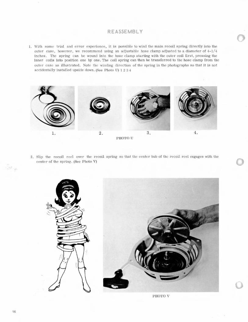
l. With some trial and error experience , it is possible to wind the main recoil spring directly into the outer case , however, we recommend using an adjustable hose clamp adjusted to a diameter of 4-1/4 inches . The spring can be wound into the hose clamp starting with the outer coil first, pressing the inne r coils into position one by one . The coil spr ing can then be transfer red to the hose clamp fro m the
outer case as illustrated . Note the winding direction of the spring in the photographs so that it is not accidentally installed upside down. (See Photo U) 1 2 3 4
1. 2 . 3. 4. P HOTO U
2. Slip the recoil r eel over the recoil spt'ing so that the center hub of the recoil reel engages wi th the center of the spring . (See Photo V)
P HOTO V
() PHOTO W r
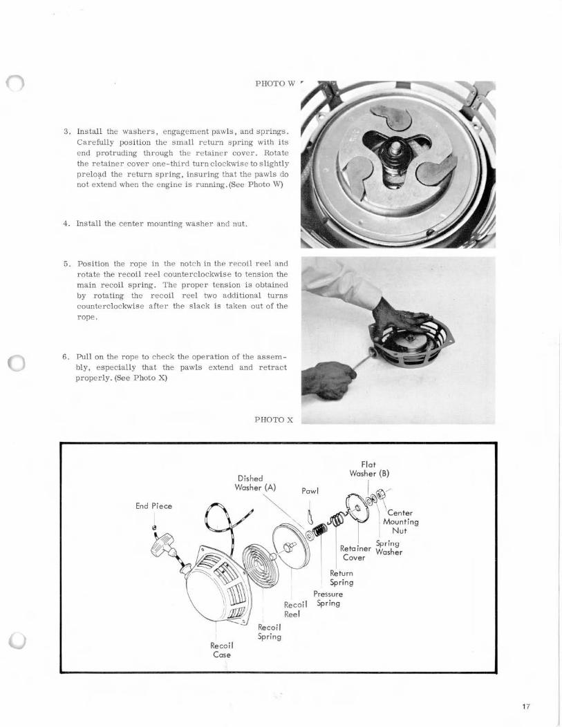
3. Install the washers, engagement pawls, and springs. Carefully position the small return spring with its end protruding through the retainer cover. Rotate the retainer cover one-third turn clockwise to slightly prelo~d the return spring, insuring that the pawls do not extend when the engine is running . (See Photo W)
4. Install the center mounting washer and nut.
5. Position the rope in the notch in the recoil reel and rotate th.e recoil reel counterclockwise to tension the main recoil spring. The proper tension is obtained by rotating the recoil reel two additional turns counterclockwise after the slack is taken out of the rope.
6. Pull on the rope to check the operation of the assembly, especially that the pawls extend and retract properly. (See Photo X)
End Piece
Re coil Case
PHOTO X
Recoi l Spring
Recoil Reel
Pressure Spring
17
18
section 7
I.S.O. METRIC INFORMATION
INFORMATION ON STANDARD HARDWARE ITEMS
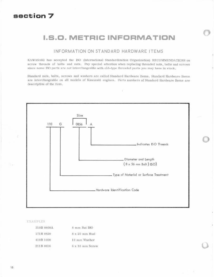
K.A WASAKI has accepted the ISO (International Standardization Organization) RECOMMEND:\ TIONS on screw threads of bolts and nuts. Pay special attention when replacing threaded nuts, bolts and screws since some ISO pllrts llre not intPr~hangPllble with old-type threaded parts you may have in stock.
Standard nuts, bolts, screws and washers are called Standard Hardware Items. Standard Hardware Items are interchangeable on all models of Kawasaki engines . Parts numbers of Standard Hardware Items are descriptive of the item.
Size
110 G 0856 I A
~T __ _ Indicates ISO Threads
L------------ Diameter and Length
( 8 x 56 mm Bolt ) ISO )
L-------------- Type of Material or Surface Treatment
.__-----------Hardware Identification Code
EXA:IIPI rs
310B 0800A
171H 0820
410B 1000
211B 0616
8 mm Nut ISO
8 x 20 mm Stud
10 mm Washer
6 x 16 mm Screw
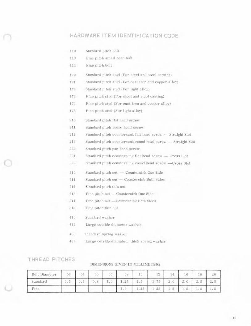
HARDWARE ITEM IDENTIFICATION CODE
1111 o:>tand:l!'d pitch !Jolt
ti:J Fine pitch small head bolt
11-± F ine pitd1 bnlt
170 Stancl:ll'll pitch stud (Fvr steel and stee l t·a~ting)
171 Standard pitch stud (Fut· cast irun and L'U)JJH'l' allu1)
1 7'.!. Standard pitch sturl (For light alloy)
17:3 Fine pitch stud (For steel and steel casting)
17.+ E'ine pitch simi (Fot cast iron and coppe r alloy)
175 Fine pitch -;tud (F111' light alloy)
210 Standal'd pitt'l1 flat head '3<' re\1
211 Standard pitch round head screw
212 Standanl pitch countersunk flat head screw - Straigh t Sl o t
213 Standard pitch C\Juntenal!1k I'OLmd ht.!ad screw - Stt·aight Sl ot
220 Standard pitch pan head sc-rew
'.!.21 Stanrl;.ll'd pitch cmantcrsunk flat. head screw - Cross Slot
222 Standard pitch cuunt<>rsunk round head sc1·ew -Cross '3lot
310 Standard pitch nut - Countersink One Side
:lll Standard pikh nut - Countersink Both Sides
:112 Standard pitch thin nut
~ll3 Fine pitch 11Ltl - Countersink One Side
:31·-1 Fine pitch nul -Countersink Doth Sides
315 Fine pil<.:h thin nllt
II 0 Standard \\:lsher
Ill Large outside diameter washct·
lliO Sbndard spring \\ashel'
l(il Large outside diameter, thicl< spring- washe•
THREAD PITCHES JJThl ENSIONS GIVEN I N 1\ITLLTl\IE TERS
Bolt Diamete r 03 04 05 06 OR 10 1~ 1-+ 111 ll:l 20
Standard 0.5 0. 7 0. 8 1.0 1. 25 1.5 1. 75 2 . 0 ~ . 0 '] r.. - . ;J 2 . :i
F ine 1.0 1. 2:) l . 25 l. S I . 5 l . .J 1 . 5
19

20
METRIC EQUIVALENTS
One inch is approximatcl) ~qual to '?5 mm, ::!:1 . 4 mm tu be mn1·c exact .
One millimeter is approximately equa l to O. tHU inch . 0 . 0:3fl4 inch t.o be more exact.
T o Change:
Inches to millimeters (111111), mu ltiply inches b~ :?5 . L
l\Iillimeters to inches, multipl) millimct\.;r::; b_y u. u:w.1.

Kawasaki Motors Corp. 5100 EDINA INDUSTRIAL BLVD. MINNfAPOLIS MINNESOTA 5.5 4 35
LITHO IN U .S A