Shock Response Spectrum (SRS) Vibration Control Software · to remove harmonics and out-of-band...
16
Features Easy Test Entry Frequency/amplitude breakpoints of the background random acceleration spectrum are entered in an easy to read tabular form using frequency and amplitude breakpoints. 200 separate frequency/amplitude breakpoints can be entered, allowing entry of virtually any test. SRS Analysis SRS Package adds Shock Response Spectrum (SRS) plots to shock and transient capture test modes. SRS Generation Supports many generation techniques including linear and exponential chirp, wavesyn, burst random, linear and exponential chirp on burst random, enveloped random, burst sine, or iterate from user waveform. Manual Wavelet Manipulation Manually adjust all the parameters of the underlying wavelets, or allow VibrationVIEW to automatically create and run without intervention. Data Plots SRS Pseudo Velocity and SRS Acceleration plots. Acceleration for primary (+), primary (-), or Maxi-Maxi. Graphs can be easily auto-scaled or zoomed, and cursors displayed. Data and text annotations can be easily placed on the graphs, with data values updated live as the data changes. Shock Response Spectrum (SRS) Vibration Control Software A variety of waveform synthesis generation techniques included. SRS is available as an optional test capability under ShockVIEW test module.
Transcript of Shock Response Spectrum (SRS) Vibration Control Software · to remove harmonics and out-of-band...

FeaturesEasy Test Entry Frequency/amplitude breakpoints of the background random acceleration spectrum are entered in an easy to read tabular form using frequency and amplitude breakpoints. 200 separate frequency/amplitude breakpoints can be entered, allowing entry of virtually any test.
SRS Analysis SRS Package adds Shock Response Spectrum (SRS) plots to shock and transient capture test modes.
SRS Generation Supports many generation techniques including linear and exponential chirp, wavesyn, burst random, linear and exponential chirp on burst random, enveloped random, burst sine, or iterate from user waveform.
Manual Wavelet Manipulation Manually adjust all the parameters of the underlying wavelets, or allow VibrationVIEW to automatically create and run without intervention.
Data Plots SRS Pseudo Velocity and SRS Acceleration plots. Acceleration for primary (+), primary (-), or Maxi-Maxi. Graphs can be easily auto-scaled or zoomed, and cursors displayed. Data and text annotations can be easily placed on the graphs, with data values updated live as the data changes.
Shock Response Spectrum (SRS)Vibration Control Software A variety of waveform synthesis generation techniques included. SRS is available as an optional test capability under ShockVIEW test module.
FeaturesEasy Test Entry Enter frequency/amplitude breakpoints in an easy to read table form. Operator can select to control constant or ramped acceleration, velocity, or displacement. Automatically calculate and enter the frequency of intersection between any combination of constant acceleration, velocity, or displacement lines. Over 1000 separate frequency/amplitude breakpoints can be entered, allowing entry of virtually any test spec.
Sweep Type Either linear (Hz/minute or minutes/sweep) or logarithmic (octave/minute, decade/minute, minutes/sweep) sweeps can be specified. Sweep rate can be changed in the test while running.
Test Duration Test duration can be entered in terms of length of time, number of sine wave cycles, or number of sweeps.
Tone Tests Sequences of fixed-frequency tones of a specified acceleration, velocity, or displacement can be run. Looping functions allow easy entry of repeating tone sequences.
Control Channels The control signal can be a single input channel, or configured from 2 to 32 input channels with either multi-channel averaging or (optional) multi-channel extremal control.
Frequency Range Standard frequency range is DC-4,990Hz. The frequency range can be extended up to 32,000Hz with the VR9103 High Frequency option.
Sine Resonance Phase Track & Dwell - SRTD (Optional) VR9105 Transmissibility peaks can be automatically detected from a sine sweep, and then dwell tests run at the detected resonance frequencies for a specified time duration or number of sine wave cycles. In a sine dwell test, the controller can automatically track the resonance frequency to keep the
output on resonance even when fatigue damage causes the resonance frequency to shift.
Configurable Safety Limits The controller can be configured to abort if the controlled acceleration goes above or below the desired level by an operator-configured number of dB. Abort limits can also be enabled for individual monitoring channels. Drive limits can be configured to protect from overdriving your shaker in case of failed accelerometers.
Tracking Filters Input channels have individually selectable tracking filters to remove harmonics and out-of-band noise from the measurements. The tracking filter bandwidth and signal averaging is user configurable.
Data Storage All of the test data can be stored to the disk for later retrieval. Data storage can be done manually, or programmed to automatically save at user-defined intervals.
Multi-Channel Extremal Allows more than one input channel for control in a control strategy where the highest, lowest or an average of accelerometer readings will be used for control of the test.
Manual Control The frequency sweep and amplitude level can be manually controlled through the mouse.
Reference Output-COLA The second output channel supplies a 1-volt constant amplitude reference signal. The phase of this signal relative to the main output can be fixed at any phase or set to shift at a configurable rate. This signal may be used to trigger a strobe light or other measurement device requiring triggering lock with the output signal.
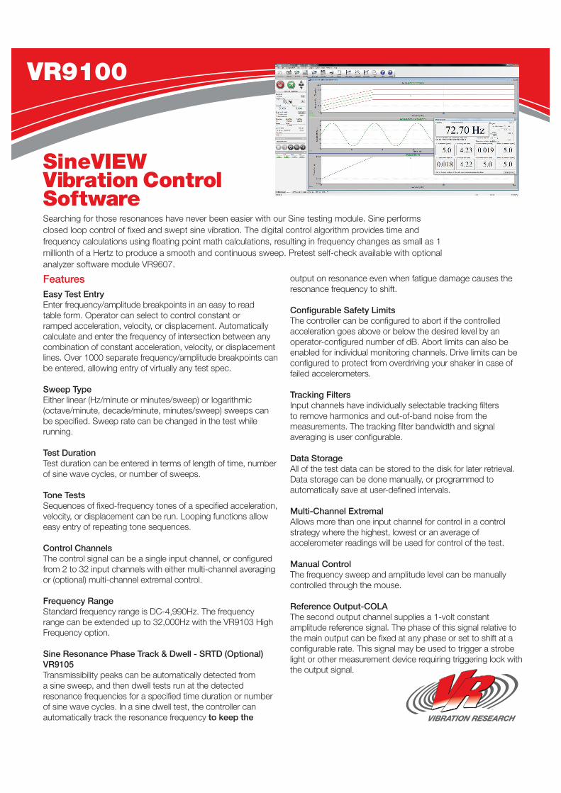
SineVIEW Vibration Control SoftwareSearching for those resonances have never been easier with our Sine testing module. Sine performs closed loop control of fixed and swept sine vibration. The digital control algorithm provides time and frequency calculations using floating point math calculations, resulting in frequency changes as small as 1 millionth of a Hertz to produce a smooth and continuous sweep. Pretest self-check available with optional analyzer software module VR9607.
VR9100

Technical Specifications Available Options
Test Duration Can be entered in terms of length of time, number of sine wave cycles or number of sweeps.
Sweep TypeLinear from 0 – 6,000 Hz/min or logarithmic from 0 – 100 octaves/min. Sweep rate can be changed while test is running.
Tone Tests
Sequences of fixed-frequency tones (dwells) of a specified acceleration, velocity or displacement can be run. Looping functions allow easy entry of repeating tone sequences.
Manual Control The frequency sweep and amplitude level can be manually controlled with the mouse.
BreakpointsUp to 1,024 amplitudes of A, V, or D, constant or slope changes at defined frequencies.
Large Numerical Readout
A configurable large numeric readout displays the current test frequency and channel amplitudes.
Multi-Channel Extremal
Allows more than one input channel for control in a control strategy where the maximum, minimum or an average of channels will be used for control.
Independent Channel Notching
Assigns maximum limiting breakpoint profiles to individual channels.
VR9100
SineVIEW Vibration Control Software
High Frequency For Sine – VR9103
Extends upper frequency for Sine control from 4,990 Hz to 50,000 Hz, (does not require an export license).
Sine Resonance Phase Track & Dwell Control (SRTD) – VR9105
Automatically generate a table of the top 10 resonance points on your product. The relationship between 2 channels is compared. Also, tracked dwell function is enabled, allowing the controller to automatically vary the frequency to track the resonance.
Constant Output Level Adapter (COLA) – VR9104
Turns on the auxiliary output on the rear of the VR9500 Revolution unit, and sends out a selectable voltage sine, square or pulsed reference signal at the frequency of the currently running sine wave. Also allows the frequency or phase to slip off the fundamental frequency, so bending action on a part can be observed with a stroboscope.
Accelerometer Calibration Verification Package – VR9106
Provides an easy interface to calculate accelerometer sensitivity. This will allow the user to perform a sine sweep, control a reference accelerometer and produce a calibration report suitable for record keeping. Automatically calculates the accelerometer sensitivity at the chosen reference frequency.
Step Test Mode – VR9107
Frequency Stepping Test: Cycle on/off for user-specified time at discrete frequencies. Linear or Logarithmic frequency step rates can be used. Stepped frequency sine tests such as those used in MIL-STD-167 are supported.
Data plots A multitude of graphical display options are available, including peak acceleration, peak velocity, peak-to-peak displacement, output drive, channel-to-channel transmissibility, and phase as a function of either frequency or time. Graphs can be easily auto-scaled or zoomed, and cursors displayed. Data and text annotations can be easily placed on the graphs, with data values updated live as the data changes.
Independent Channel Notching Profiles Assigns maximum limiting breakpoint profiles to individual channels. The drive output will be limited (or ´notched´) if necessary to keep the input amplitude for that channel below the defined profile.
Accelerometer Calibration Package (Optional) VR9106 Provides an easy interface to calculate accelerometer sensitivity. This will allow the user to perform a sine sweep, controlling on a reference accelerometer, and produce a calibration report suitable for calibration record keeping. Automatically calculates )the accelerometer sensitivity at the chosen frequency.
Technical Specifications
Available Options

FeaturesEasy Test Entry Frequency/amplitude breakpoints are entered in an easy-to-read tabular form using either frequency and amplitude breakpoints or by entering one endpoint and the desired dB/octave slope. Over 1,000 separate frequency/amplitude breakpoints can be entered, allowing entry of virtually any test spec.
Lines The controller comes standard with 50 to 26,000 user-selectable lines of control to provide the frequency resolution required for testing. You can analyze up to 32,000Hz with the VR9203 High Frequency option, without sacrificing resolution.
Frequency Range The standard frequency range is DC-4,990Hz. The frequency range can be extended up to 32,000Hz with the VR9203 High Frequency option (note- this option requires an export license for end users outside USA).
Control Channels The control signal can be a single input channel, or configured from 2 to 32 input channels with either multi-channel averaging or optional multi-channel notching.
Multiple Shakers One to 4 control loops can be run simultaneously to independently control up to 4 shakers with 4 individually configurable and statistically independent waveforms.
Multi-Channel Extremal Allows more than 1 input channel for control in a strategy where the highest accelerometer reading will be used for control of the test.
Data Storage All of the test data can be stored to the disk for later retrieval. Data storage can be done manually, or programmed to automatically save at user-defined intervals.
Test & Level Scheduling Tests can be scheduled to run a user-defined length of time, the spectrum level can be scaled by a specified dB level, percentage or scaled for a specified RMS acceleration. Level schedules can be entered to run various durations at different acceleration levels. Levels can be changed while the test is running.
Independent Channel Notching Profiles Assign maximum limiting breakpoint profiles to individual channels. The drive output will be limited (or notched) if necessary to keep the input spectrum for that channel below the defined profile. Up to 1,024 breakpoints can be entered for each channel, or the limit can be entered simply as a dB level relative to the demand profile. In addition, minimum limits may be defined to boost the drive output if a channel is below a defined profile. The notching profiles may also be used as spectrum abort limits, so that abort limit breakpoint profiles can be assigned to each individual channel, and if that channel reaches the defined limit the test will safely shut down.
Configurable Safety Limits To protect your test article and shaker system, configurable acceleration limits, line limits and drive limits can be set by the user. The control input is also verified against shaker acceleration and displacement limits.
Data Plots Many graphical display options are available, including acceleration spectral density, output voltage spectral density and channel-to-channel transmissibility. Graphs can be easily auto-scaled or zoomed, and cursors displayed. Data and text annotations can be easily placed on the graphs, with data values updated live as the data changes.
RandomVIEW Vibration Control SoftwareRandom vibration testing provides a more closely matched vibration to your end-use environment. With our Random vibration test module you get the highest possible control with ease of use. Random performs real-time closed-loop control of PSD profiles. All inputs are simultaneous, which means there is an A/D assigned to each input (not multiplexed). The inputs continuously take data, and there are no “unsampled” periods. Highly evolved control algorithms will control electrodynamic, and servo-hydraulic or servo-electric shakers. A pretest self-check is available with optional analyzer software module VR9607.
VR9200

Frequency RangeDC to 50,000Hz, user selectable. Up to 4,990 standard; High Frequency option extends to 50,000Hz (requires export license).
Loop Time Inner control loop: 10mS typical
Degrees of Freedom User adjustable from 2 to 1,000
Drive ClippingClipping modes include digital, analog and silent clipping. Can be set at any level between 1 sigma up.
Breakpoints
Up to 1,024 frequency/amplitude breakpoints with automatic slope (dB/octave) calculations, or manually set slope values between frequencies.
Units English, SI, Metric, mixed, user specified.
Level Types
Scale entered profile by % level, by dB level, or to an RMS acceleration level. Wait for operator intervention, wait for a timed interval, level looping, enter form, save report, record, view report, start, stop and many more.
Abort/Alarm
High and low profile limits specified either universally or independently at each breakpoint in dB or % with respect to reference. RMS high and low limits calculated automatically from profiles or specified by user.
Profile View
Profile graphics shown and updated as profile is created. Automatic listing of RMS Acceleration, Velocity and Displacement values for profile. Profile operating levels are compared to the shaker parameter table.
Spectrum Lines 50 to 26,000 lines
Sample Rate 100 to 200,000Hz
Frequency Resolution As fine as 0.1Hz
Closed Loop Dynamic Range 100dB typical
Number of Test Schedule Levels 2,000
Technical Specifications
VR9200
RandomVIEW Vibration Control Software
VR9207 Random-on-Random
Run controlled spectrum random tests with swept random “tones” superimposed on a random background.
VR9206 Sine-on-Random
Run mixed-mode tests with sine tones superimposed on a random background.
VR9205 Kurtosion® Kurtosis control.
VR9204 Random Import
Import analog or digital time data to automatically generate a profile. Also imports PSD data.
VR9203 High Frequency For Random
Extends upper frequency for Random control from 4,990Hz to 50,000Hz, requires an export license.
Available Options
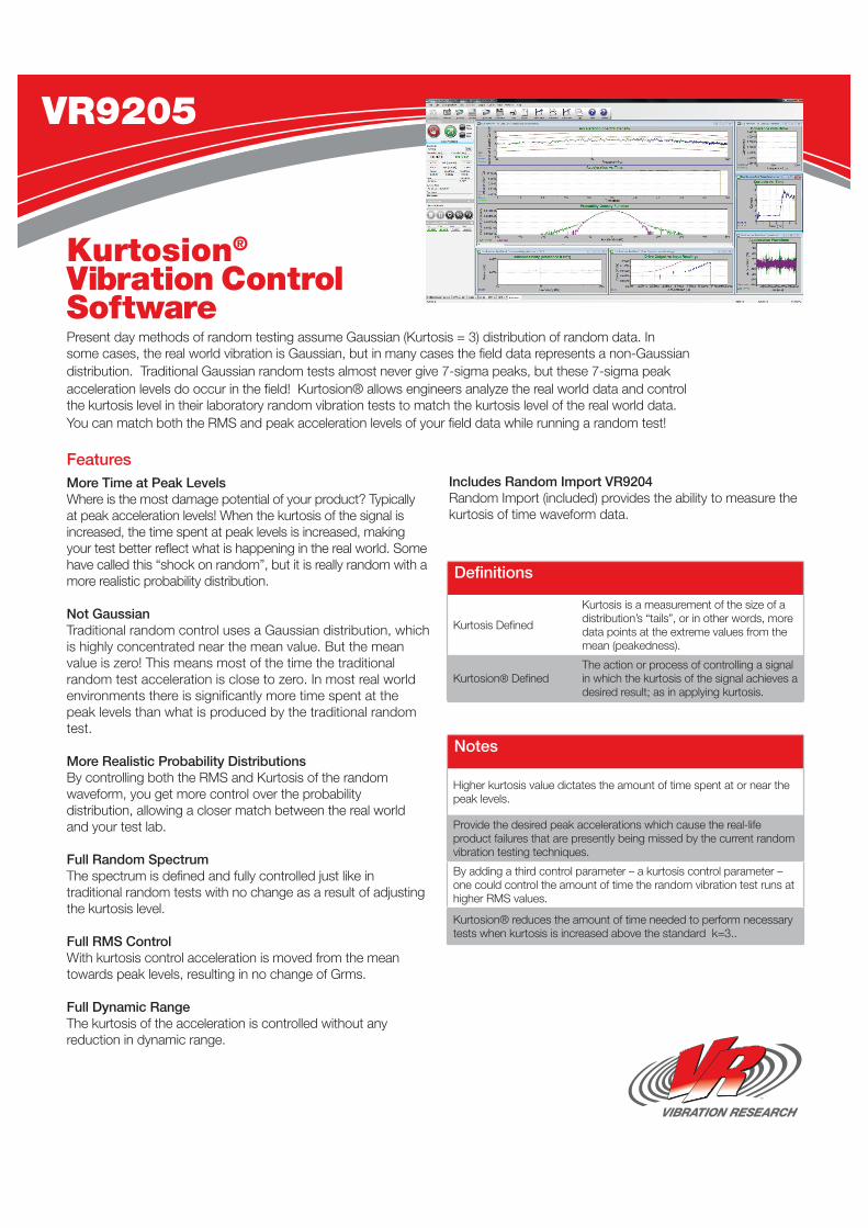
FeaturesMore Time at Peak Levels Where is the most damage potential of your product? Typically at peak acceleration levels! When the kurtosis of the signal is increased, the time spent at peak levels is increased, making your test better reflect what is happening in the real world. Some have called this “shock on random”, but it is really random with a more realistic probability distribution.
Not Gaussian Traditional random control uses a Gaussian distribution, which is highly concentrated near the mean value. But the mean value is zero! This means most of the time the traditional random test acceleration is close to zero. In most real world environments there is significantly more time spent at the peak levels than what is produced by the traditional random test.
More Realistic Probability Distributions By controlling both the RMS and Kurtosis of the random waveform, you get more control over the probability distribution, allowing a closer match between the real world and your test lab.
Full Random Spectrum The spectrum is defined and fully controlled just like in traditional random tests with no change as a result of adjusting the kurtosis level.
Full RMS Control With kurtosis control acceleration is moved from the mean towards peak levels, resulting in no change of Grms.
Full Dynamic Range The kurtosis of the acceleration is controlled without any reduction in dynamic range.
Includes Random Import VR9204 Random Import (included) provides the ability to measure the kurtosis of time waveform data.
Kurtosion® Vibration Control SoftwarePresent day methods of random testing assume Gaussian (Kurtosis = 3) distribution of random data. In some cases, the real world vibration is Gaussian, but in many cases the field data represents a non-Gaussian distribution. Traditional Gaussian random tests almost never give 7-sigma peaks, but these 7-sigma peak acceleration levels do occur in the field! Kurtosion® allows engineers analyze the real world data and control the kurtosis level in their laboratory random vibration tests to match the kurtosis level of the real world data. You can match both the RMS and peak acceleration levels of your field data while running a random test!
VR9205
Kurtosis Defined
Kurtosis is a measurement of the size of a distribution’s “tails”, or in other words, more data points at the extreme values from the mean (peakedness).
Kurtosion® DefinedThe action or process of controlling a signal in which the kurtosis of the signal achieves a desired result; as in applying kurtosis.
Definitions
Higher kurtosis value dictates the amount of time spent at or near the peak levels.
Provide the desired peak accelerations which cause the real-life product failures that are presently being missed by the current random vibration testing techniques.
By adding a third control parameter – a kurtosis control parameter – one could control the amount of time the random vibration test runs at higher RMS values.
Kurtosion® reduces the amount of time needed to perform necessary tests when kurtosis is increased above the standard k=3..
Notes

FeaturesEasy Test Entry Frequency/amplitude breakpoints of the background random acceleration spectrum are entered in an easy to read tabular form using either frequency and amplitude breakpoints, or by entering one endpoint and the desired dB/octave slope. Over 1000 separate frequency/amplitude breakpoints can be entered, allowing entry of virtually any test.
Sine Tones 1 to 32 true floating-point precision sine tones can be superimposed on the background random spectrum, and swept back-and-forth between frequencies at a user-programmable rate. The amplitude and frequency sweep parameters are all user programmable. Up to 200 separate frequency/amplitude breakpoints can be entered, allowing entry of virtually any test spec.
Lines The controller comes standard with 50 to 1600 lines of control to provide you with the frequency resolution required for your test.
Control Channels The control signal can be a single input channel, or configured from 2 to 32 input channels with either multi-channel averaging or optional multi-channel notching for the random signal.
Test & Level Scheduling Tests can be scheduled to run a user-defined length of time, the spectrum level can be scaled by a specified dB-level, percentage, or scaled for a specified RMS acceleration. Level schedules can be entered to run various durations at different acceleration levels.
Data Storage All of the test data can be stored to the disk for later retrieval. Data storage can be done manually, or programmed to automatically save at user-defined intervals.
Data Plots Many graphical display options are available, including acceleration spectral density, output voltage spectral density and channel-to-channel transmissibility. Graphs can be easily auto-scaled or zoomed, and cursors displayed. Data and text annotations can be easily placed on the graphs, with data values updated live as the data changes.
Configurable Safety Limits To protect your test article and shaker system, configurable acceleration limits, line limits and drive limits can be set by the user. The control input is also verified against shaker acceleration limits.
Reference Output (VR9104) The second output channel supplies a synchronization signal of the first sine tone .
Random Import (VR9204) Import analog or digital time data to automatically generate a profile. Imports PSD data, too.
Sine-on-RandomSine-on-SineVibration Control SoftwareRun mixed-mode tests with sine tones superimposed on a random background. Sine-on-RandomVIEW is available as an optional test capability under RandomVIEW test module. Also enables Sine-on-Sine testing by running multiple sine tones superimposed on a sine background.
VR9206
1 – 32 true floating-point precision sine tones can be superimposed on the background random spectrum.
Sweep back-and-forth between frequencies at a userprogrammable rate.
Amplitude, bandwidth and frequency sweep are all userprogrammable.
Up to 50 separate frequency/amplitude breakpoints per sine tone can be entered.
200 – 6,500 lines of control.
Technical Highlights
FeaturesEasy Test Entry Frequency/amplitude breakpoints of the background random acceleration spectrum are entered in an easy to read tabular form using either frequency and amplitude breakpoints, or by entering one endpoint and the desired dB/octave slope. Up to 1024 separate frequency/amplitude breakpoints can be entered, allowing entry of virtually any test.
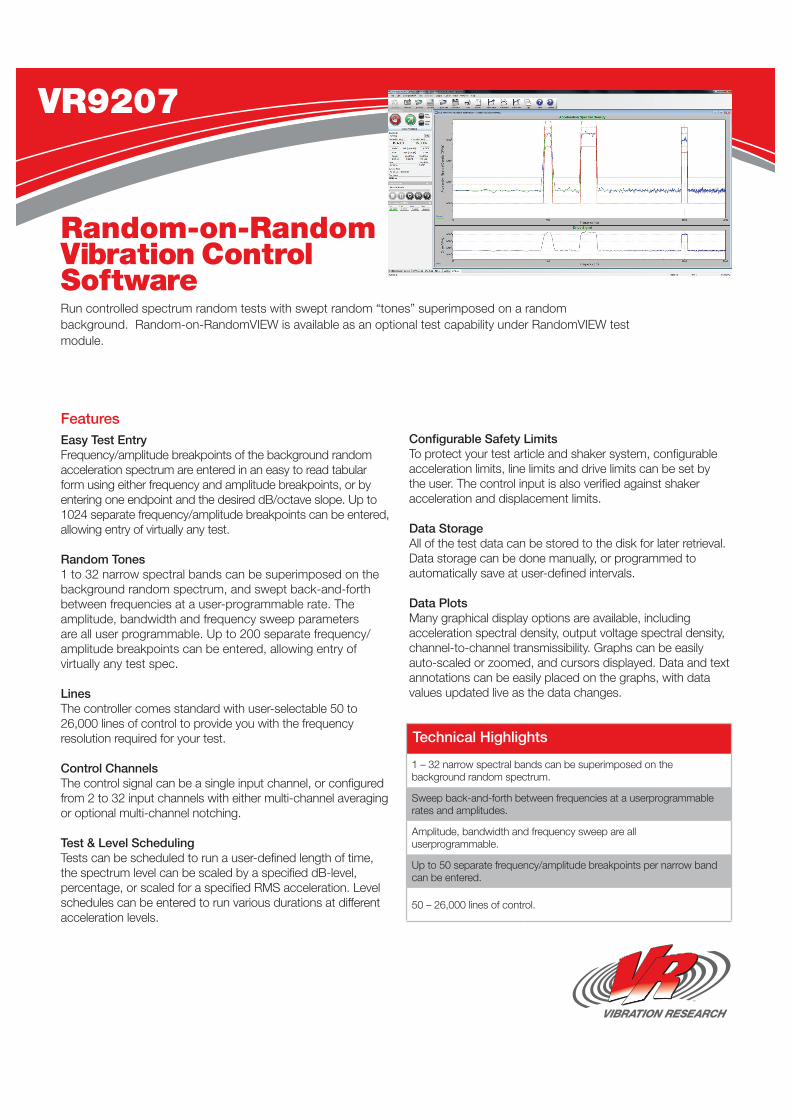
Random Tones 1 to 32 narrow spectral bands can be superimposed on the background random spectrum, and swept back-and-forth between frequencies at a user-programmable rate. The amplitude, bandwidth and frequency sweep parameters are all user programmable. Up to 200 separate frequency/amplitude breakpoints can be entered, allowing entry of virtually any test spec.
Lines The controller comes standard with user-selectable 50 to 26,000 lines of control to provide you with the frequency resolution required for your test.
Control Channels The control signal can be a single input channel, or configured from 2 to 32 input channels with either multi-channel averaging or optional multi-channel notching.
Test & Level Scheduling Tests can be scheduled to run a user-defined length of time, the spectrum level can be scaled by a specified dB-level, percentage, or scaled for a specified RMS acceleration. Level schedules can be entered to run various durations at different acceleration levels.
Configurable Safety Limits To protect your test article and shaker system, configurable acceleration limits, line limits and drive limits can be set by the user. The control input is also verified against shaker acceleration and displacement limits.
Data Storage All of the test data can be stored to the disk for later retrieval. Data storage can be done manually, or programmed to automatically save at user-defined intervals.
Data Plots Many graphical display options are available, including acceleration spectral density, output voltage spectral density, channel-to-channel transmissibility. Graphs can be easily auto-scaled or zoomed, and cursors displayed. Data and text annotations can be easily placed on the graphs, with data values updated live as the data changes.
Random-on-Random Vibration Control SoftwareRun controlled spectrum random tests with swept random “tones” superimposed on a random background. Random-on-RandomVIEW is available as an optional test capability under RandomVIEW test module.
VR9207
1 – 32 narrow spectral bands can be superimposed on the background random spectrum.
Sweep back-and-forth between frequencies at a userprogrammable rates and amplitudes.
Amplitude, bandwidth and frequency sweep are all userprogrammable.
Up to 50 separate frequency/amplitude breakpoints per narrow band can be entered.
50 – 26,000 lines of control.
Technical Highlights

FeaturesCustom Frequency Axis Normally, random import is calculated linearly based on number of lines. The FDS is calculated on a custom logarithmic frequency axis. You can set the frequency axis spacing and the start/end frequency on the user interface. User is in control of how many points and which points to calculate.
Time Domain Calculation Calculation through time domain, not frequency domain to account for kurtosis you will likely see in the real world. The Fatigue Damage Spectrum is based on the response of single degree of freedom systems rather than FFTs.
Display Imported File Statistics Displays peak acceleration, velocity, displacement as well as the kurtosis of the time history file. This provides a quick and easy way to determine the statistics of a waveform.
Configurable Process Parameters The user can define the slope of the s/n curve (beta) and quality factor (Q).
Reduce Test Time User sets test item target life based on product specifications, as well as test duration. The software automatically calculates ratios that will produce the same amount of fatigue damage in shorter test time.
Analysis to Control With one mouse click, bring your new random breakpoints into a control profile. Go from a time waveform to a breakpoint profile and start controlling on that profile all in one program.
Includes Random Import (VR9204) Compare multiple methods of generating a random profile.
Fatigue DamageSpectrum (FDS)Vibration Control SoftwareMeasure your products fatigue and calculate its lifespan. For years people have used methods to calculate the lifespan of a product based on the material s/n curve. Rain flow analysis techniques from your product are applied to the actual measured vibration, equivalent fatigue is quantified and time to failure is calculated. Commonly used life acceleration techniques are applied to shorten test time.
VR9209
FDS Calculation Method Henderson-Piersol
Supported File Extensions .txt, .csv, .log, .asc, .dat, .vrp, .vrd, .vrw
Frequency Range 0 up to 1/2 the sample rate of the file.
Frequency Axis Logarithmic
Technical Specifications
VR-OBSV Measure waveforms with the ObserVR and import into a random profile.
VR9600 RecorderVIEWMeasure waveforms with the VR9500 and RecorderVIEW and import into a random profile.
Available Options

FeaturesStandard Pulse Shapes Select from half-sine, haversine, initial-peak sawtooth, terminal-peak sawtooth, triangle, trapezoid and square pulse shapes.
Control Channels The control signal can be a single input channel, or an average of 2 to 4 different input channels.
Test & Level Scheduling Repeat a pulse from 1 to more than 2 billion times, with a configurable repetition rate. Tests can be configured to run pulses at different amplitude levels.
Configurable Safety Limits To protect your test article and shaker system, configurable acceleration and drive limits can be set by the user. The control input is also verified against shaker force, velocity, and displacement ratings.
Equalization The controller automatically equalizes the response of the shaker/fixture/product prior to running the test. This equalization can be memorized and stored with the test to quickly start a test at full equalized level.
Data Storage All of the test data can be stored to the disk for later retrieval. Data storage can be done manually, or programmed to automatically store at user-defined pulse intervals.
Reference Output (Optional) VR611 The second output channel supplies a reference signal to indicate when a pulse is running. This can be used to trigger external measurement devices.
Earthquake/Transient Waveforms Control (Optional) VR9301 Used to import a time domain user specified transient. Typical use is the Belcore earthquake test.
Data Plots Many graphical display options are available, including acceleration, velocity, displacement, output voltage, acceleration and drive spectra. Graphs can be easily auto-scaled or zoomed, and cursors displayed. Data and text annotations can be easily placed on the graphs, with data values updated live as the data changes.
Shock Response Spectra Control - SRS (Optional) VR9302 Runs a shock pulse defined by a frequency vs G peak table. Many different waveform synthesis generation techniques included.
ShockVIEW Vibration Control SoftwareClassical shock performs closed loop control of transient waveforms. Classical Shock performs closed loop control of transient waveforms. The entire transient period is sampled simultaneously and gap free.The needed drive is calculated between each pulse. All of the classical types are supported. There are several methods of optimizing the displacement requirements of a given pulse.
VR9300
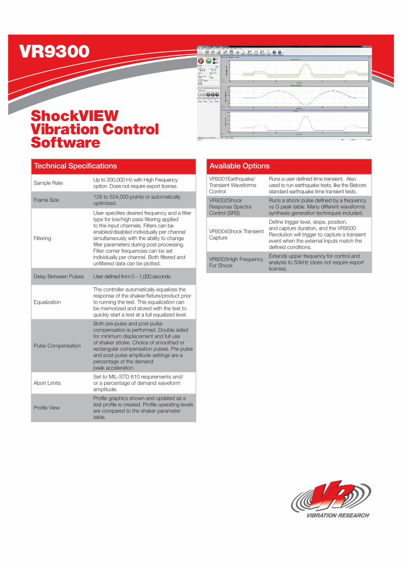
Sample Rate Up to 200,000 Hz with High Frequency option. Does not require export license.
Frame Size 128 to 524,000 points or automatically optimized.
Filtering
User specifies desired frequency and a filter type for low/high pass filtering applied to the input channels. Filters can be enabled/disabled individually per channel simultaneously with the ability to change filter parameters during post processing. Filter corner frequencies can be set individually per channel. Both filtered and unfiltered data can be plotted.
Delay Between Pulses User defined from 0 – 1,000 seconds.
Equalization
The controller automatically equalizes the response of the shaker/fixture/product prior to running the test. This equalization can be memorized and stored with the test to quickly start a test at a full equalized level.
Pulse Compensation
Both pre-pulse and post-pulse compensation is performed. Double sided for minimum displacement and full use of shaker stroke. Choice of smoothed or rectangular compensation pulses. Pre-pulse and post-pulse amplitude settings are a percentage of the demand peak acceleration.
Abort LimitsSet to MIL-STD 810 requirements and/or a percentage of demand waveform amplitude.
Profile View
Profile graphics shown and updated as a test profile is created. Profile operating levels are compared to the shaker parameter table.
ShockVIEW Vibration Control Software
VR9301Earthquake/Transient Waveforms Control
Runs a user defined time transient. Also used to run earthquake tests, like the Belcore standard earthquake time transient tests.
VR9302Shock Response Spectra Control (SRS)
Runs a shock pulse defined by a frequency vs G peak table. Many different waveforms synthesis generation techniques included.
VR9304Shock Transient Capture
Define trigger level, slope, position, and capture duration, and the VR9500 Revolution will trigger to capture a transient event when the external inputs match the defined conditions.
VR9303High Frequency For Shock
Extends upper frequency for control and analysis to 50kHz (does not require export license).
Technical Specifications Available Options
VR9300
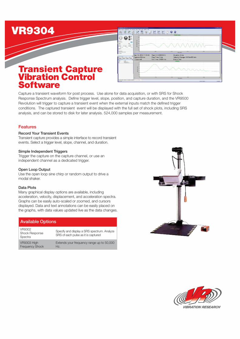
FeaturesRecord Your Transient EventsTransient capture provides a simple interface to record transient events. Select a trigger level, slope, channel, and duration.
Simple Independent TriggersTrigger the capture on the capture channel, or use an independent channel as a dedicated trigger.
Open Loop OutputUse the open loop sine chirp or random output to drive a modal shaker.
Data PlotsMany graphical display options are available, including acceleration, velocity, displacement, and acceleration spectra. Graphs can be easily auto-scaled or zoomed, and cursors displayed. Data and text annotations can be easily placed on the graphs, with data values updated live as the data changes.
Transient CaptureVibration Control SoftwareCapture a transient waveform for post process. Use alone for data acquisition, or with SRS for Shock Response Spectrum analysis. Defi ne trigger level, slope, position, and capture duration, and the VR9500 Revolution will trigger to capture a transient event when the external inputs match the defi ned trigger conditions. The captured transient event will be displayed with the full set of shock plots, including SRS analysis, and can be stored to disk for later analysis. 524,000 samples per measurement.
VR9304
VR9302Shock Response Spectra
Specify and display a SRS spectrum. Analyze SRS of each pulse as it is captured
VR9303 High Frequency Shock
Extends your frequency range up to 50,000 Hz.
Available Options

FeaturesField Data Replicator Reference (Output) VR9401 Play any uncompensated reference waveform fully synchro-nized with the control waveform. Useful for providing reference waveforms to a spectrum analyzer for external verification of results. Also useful for providing a pre-recorded trigger signal (e.g. tachometer, cylinder firing, etc.) synchronized to the vibra-tion. Can also be used for synchronizing additional environ-mental factors (e.g. motor RPM, temperature, etc.) with the recorded vibration.
Data Import Import waveforms from data recorders using an analog input, or import from digital wave or text files. Waveforms can be up to 45 hours long at a 26,000 Hz sampling rate (with VR9403 High Frequency option), or up to 1 year long at a 100 Hz sampling rate.
Test & Level Scheduling The test can be set to reproduce the waveform for a specified duration. The waveform can be scaled up or down by any factor to get the test intensity you desire. Tests can be programmed to run for various periods at different intensity levels. The amplitude can be changed while the test is running.
Multiple Shakers From 1 to 4 control loops can be run simultaneously to independently control up to 4 shakers with 4 separate waveforms.
Configurable Safety Limits To protect your test article and shaker system, configurable acceleration and drive limits can be set by the user. The control input is also verified against shaker force ratings.
Equalization The controller automatically equalizes the response of the shaker/fixture/product prior to running the test. This equalization can be memorized and stored with the test to
quickly start a test at full equalized level. The frequency range of the output signal is configurable, and a frequency band can even be notched out of the signal.
Data Storage All of the test data can be stored to the disk for later retrieval. Data storage can be done manually, or programmed to automatically save at user-defined pulse intervals.
Lines The controller comes standard with 50 to 6500 lines of control to provide you with the frequency resolution required for your test.
Data Plots Many graphical display options are available, including acceleration and drive voltage vs. time or frequency, and channel-to-channel transmissibility. Graphs can be easily auto-scaled or zoomed, and cursors displayed. Data and text annotations can be easily placed on the graphs, with data values updated live as the data changes.
Frequency Range Select the lower and upper frequency of operation while the test is running (up to 4,900Hz).
High Frequency (Optional) VR9403 Extends your operational frequency to 26,000Hz. (*Note - requires export license for end users outside of the USA)
Notch Filter Apply a notch filter while the test is running.
FDRVIEW Vibration Control SoftwareTake your field acceleration measurements, and reproduce them on your shaker in your test lab. There is no need to try to approximate your field environment through the approximations inherent in the standard random, sine, or shock tests. F.D.R.VIEW (or F.D.R.) provides the capability to replicate your field acceleration measurements and reproduce them on the shaker in the test lab. Utilizing real-time adaptive control, F.D.R. simulates the recorded time history measurements on your shaker.
VR9400
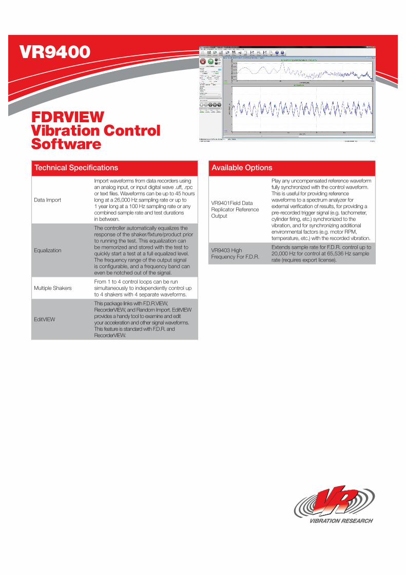
Data Import
Import waveforms from data recorders using an analog input, or input digital wave .uff, .rpc or text files. Waveforms can be up to 45 hours long at a 26,000 Hz sampling rate or up to 1 year long at a 100 Hz sampling rate or any combined sample rate and test durations in between.
Equalization
The controller automatically equalizes the response of the shaker/fixture/product prior to running the test. This equalization can be memorized and stored with the test to quickly start a test at a full equalized level. The frequency range of the output signal is configurable, and a frequency band can even be notched out of the signal.
Multiple ShakersFrom 1 to 4 control loops can be run simultaneously to independently control up to 4 shakers with 4 separate waveforms.
EditVIEW
This package links with F.D.R.VIEW, RecorderVIEW, and Random Import. EditVIEW provides a handy tool to examine and edit your acceleration and other signal waveforms. This feature is standard with F.D.R. and RecorderVIEW.
VR9401Field Data Replicator Reference Output
Play any uncompensated reference waveform fully synchronized with the control waveform. This is useful for providing reference waveforms to a spectrum analyzer for external verification of results, for providing a pre-recorded trigger signal (e.g. tachometer, cylinder firing, etc.) synchronized to the vibration, and for synchronizing additional environmental factors (e.g. motor RPM, temperature, etc.) with the recorded vibration.
VR9403 High Frequency For F.D.R.
Extends sample rate for F.D.R. control up to 20,000 Hz for control at 65,536 Hz sample rate (requires export license).
Technical Specifications
VR9400
FDRVIEW Vibration Control Software
Available Options
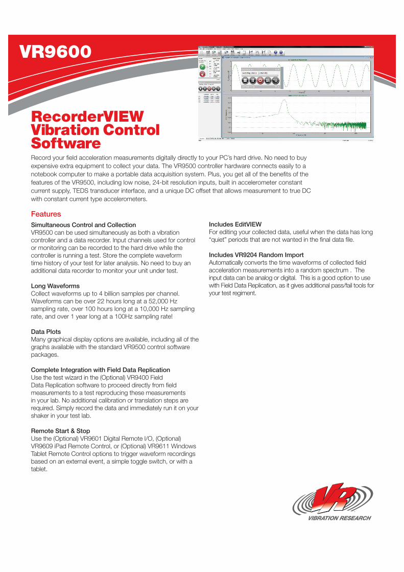
FeaturesSimultaneous Control and Collection VR9500 can be used simultaneously as both a vibration controller and a data recorder. Input channels used for control or monitoring can be recorded to the hard drive while the controller is running a test. Store the complete waveform time history of your test for later analysis. No need to buy an additional data recorder to monitor your unit under test.
Long Waveforms Collect waveforms up to 4 billion samples per channel. Waveforms can be over 22 hours long at a 52,000 Hz sampling rate, over 100 hours long at a 10,000 Hz sampling rate, and over 1 year long at a 100Hz sampling rate!
Data Plots Many graphical display options are available, including all of the graphs available with the standard VR9500 control software packages.
Complete Integration with Field Data Replication Use the test wizard in the (Optional) VR9400 Field Data Replication software to proceed directly from field measurements to a test reproducing these measurements in your lab. No additional calibration or translation steps are required. Simply record the data and immediately run it on your shaker in your test lab.
Remote Start & Stop Use the (Optional) VR9601 Digital Remote I/O, (Optional) VR9609 iPad Remote Control, or (Optional) VR9611 Windows Tablet Remote Control options to trigger waveform recordings based on an external event, a simple toggle switch, or with a tablet.
Includes EditVIEW For editing your collected data, useful when the data has long “quiet” periods that are not wanted in the final data file.
Includes VR9204 Random Import Automatically converts the time waveforms of collected field acceleration measurements into a random spectrum . The input data can be analog or digital. This is a good option to use with Field Data Replication, as it gives additional pass/fail tools for your test regiment.
RecorderVIEW Vibration Control SoftwareRecord your field acceleration measurements digitally directly to your PC’s hard drive. No need to buy expensive extra equipment to collect your data. The VR9500 controller hardware connects easily to a notebook computer to make a portable data acquisition system. Plus, you get all of the benefits of the features of the VR9500, including low noise, 24-bit resolution inputs, built in accelerometer constant current supply, TEDS transducer interface, and a unique DC offset that allows measurement to true DC with constant current type accelerometers.
VR9600
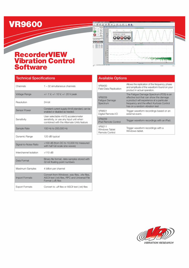
Channels 1 – 32 simultaneous channels
Voltage Range +/- 1 V, +/- 10 V, +/- 20 V peak
Resolution 24-bit
Sensor Power Constant current supply (4mA) standard, can be enabled or disabled as needed.
SensitivityUser selectable mV/G accelerometer sensitivity, or use any input unit when combined with the Alternate Units feature
Sample Rate 100 Hz to 200,000 Hz
Dynamic Range 120 dB typical
Signal-to-Noise Ratio >100 dB (from DC to 10,000 Hz measured with half-full-scale sine waves)
Interchannel Isolation >110 dB
Data Format Binary file format, data samples stored with 32-bit floating point numbers
Maximum Samples 4 billion per channel
Import FormatsConvert from Windows .wav files, .vfw files, ASCII text (.txt) files, RPC and Universal File Format (.uff) files
Export Formats Convert to .uff files or ASCII text (.txt) files
Technical Specifications
VR9600
RecorderVIEW Vibration Control Software
VR9400 Field Data Replication
Allows the replication of the frequency, phase and amplitude of the waveform found on your product in actual operation.
VR9209 Fatigue Damage Spectrum
The Fatigue Damage Spectrum (FDS) is an effective tool that can show the damage a product will experience at a particular frequency and the effect Kurtosis Control has on a random vibration test
VR9601 Digital Remote I/O
Trigger waveform recordings based on an external event.
VR9209 iPad Remote Control Trigger waveform recordings with an iPad.
VR9211 Windows Tablet Remote Control
Trigger waveform recordings with a Windows tablet.
Available Options


![arXiv:2001.05264v1 [eess.IV] 15 Jan 2020main such as Lee filter [1], Frost filter [2], Kuan filter [3], and Gamma-MAP filter [4]. Wavelet-based methods [5, 6] en-abled multi-resolution](https://static.fdocuments.us/doc/165x107/60b8d97699999d50431b52d6/arxiv200105264v1-eessiv-15-jan-2020-main-such-as-lee-ilter-1-frost-ilter.jpg)