Shivaji University, Kolhapur Department of Electrical ... Plan-SE Electrical.pdf · Describe1 the...
59
SE Electrical (Semester-IV) Page1 Shivaji University, Kolhapur Department of Electrical Engineering Course plans for S.E. (Semester-IV) Scheme of Teaching & Examination Sr. No Course Title Teaching Scheme per Week Examination (Marks) L T P Contact Hours Theory TW POE Total 1 DC Machines and Transformer 4 2 6 100 25 50 175 2 Power Electronics 3 2 5 100 25 50 175 3 Power Systems I 4 2 6 100 50 150 4 Network Analysis and Synthesis 3 3 100 100 5 Control System I 4 2 6 100 50 150 Total 18 8 26 500 150 100 750 INDEX Sr. No. Subject Code Page No. 1. DC Machines and Transformer CE 206 02 2. Power Electronics CE 207 12 3. Power Systems I CE 208 25 4. Network Analysis and Synthesis CE 209 35 5 Control System I CE 210 49
Transcript of Shivaji University, Kolhapur Department of Electrical ... Plan-SE Electrical.pdf · Describe1 the...

SE Electrical (Semester-IV) Page1
Shivaji University, Kolhapur
Department of Electrical Engineering
Course plans for S.E. (Semester-IV)
Scheme of Teaching & Examination
Sr.
No Course Title
Teaching Scheme per
Week Examination (Marks)
L T P Contact
Hours
Theory TW POE Total
1 DC Machines and
Transformer 4 2 6 100 25 50 175
2 Power Electronics 3 2 5 100 25 50 175
3 Power Systems I 4 2 6 100 50 150
4 Network Analysis
and Synthesis 3 3 100 100
5 Control System I 4 2 6 100 50 150
Total 18 8 26 500 150 100 750
INDEX
Sr. No. Subject Code Page No.
1. DC Machines and Transformer CE 206 02
2. Power Electronics CE 207 12
3. Power Systems I CE 208 25
4. Network Analysis and Synthesis CE 209 35
5 Control System I CE 210 49

SE Electrical (Semester-IV) Page2
Course plan for DC Machines and Transformers
Course Code EE 206 Course DC Machines and Transformers
Prepared by Mr.A.B.Kumbhar
Mr.S.R.Lokhande
Semester AY 2017-18, Sem II
Pre-requisites Basic knowledge in electric circuit analysis, constructional details and
operational principles of various dc machines and transformers
Course Outcomes
At the end of the course the students should be able to:
CO206.1
Describe1 the principle of electromechanical conversion. constructional details of
the DC machines and Transformers and also Extend the significance of different
connections of three phase transformers
CO206.2 Describe1 the constructional details and working of various types of the DC
machines
CO206.3 Estimate2 the performance of any DC machine (shunt, series or compound) and
analyse various speed control & braking techniques for DC motor
CO206.4 Demonstrate the performance of single phase transformer
CO206.5 Explain the construction & working of three phase transformer and extend
significance of different connections of three phase transformer
CO206.6 Explain2 special types of transformer like pulse transformer, isolation
transformers.
Mapping of COs with POs
POs
COs a b C d e f g h i J k
CO206.1 2 1 2 1
CO206.2 2 1 1
CO206.3 2 1 1 1
CO206.4 2 2 2 1
CO206.5 1 1 1 1
CO206.6 1 1 1
1
1 Mild correlation 2 Moderato correlation 3 Strong correlation
SE Electrical (Semester-IV) Page3
Course Contents
Unit
No. Title
No of
Hrs
01
ELECTROMECHANICAL ENERGY CONVERSION PRINCIPLE:
Singly Excited Magnetic System and Doubly Excited Magnetic system.
Physical concept of torque production; Electromagnetic torque and
Reluctance torque. Concept of General terms pertaining to Rotating
Machines: Electrical & Mechanical degree, Pole pitch, Coil, Generated
EMF in full pitched coil, Generated EMF in a short pitched coil, EMF
polygon, Distribution factor, Pitch factor. MMF produced by Distributed
Windings, MMF of a coil, MMF of single phase distributed Winding,
MMF waveform of Commutator machines.
06
02
DC.MACHINES :Construction of D.C. machines, commutator and brush
arrangement, EMF equation, torque equation, armature winding and its
types, armature reaction: Demagnetization and cross magnetization
ampere turns, principle of compensation, compensating winding, methods
to minimize the effect of armature reaction, Process of commutation,
Methods to improve commutation, concept of Motoring, types of motor,
Concept of back emf, characteristics of d.c. motors, Method of speed
controls, concept of braking of DC separately excited motors (Rheostatic,
Regenerative and plugging). Parallel and series operation of motor, starter
for shunt and series motor, Design of grading of resistance of starters,
testing: Losses and efficiency, Brake load test, Swinburne test,
Hopkinson’s test, Retardation test, field test. Application of Generator and
Motor.
14
03
TRANSFORMER – SINGLE PHASE: Review of EMF equation,
Equivalent Circuit and Phasor diagram of Transformer. Voltage
Regulation of Transformer: - Voltage Regulation, Condition for Zero
Voltage Regulation, Condition for Maximum Voltage Regulation.
Transformer Losses and Efficiency - Losses, Efficiency, Condition for
Maximum Efficiency, Energy Efficiency, All day Efficiency, Separation
of Hysteresis and Eddy current losses Testing of Transformer: - Polarity
Test, Load Test, Review of OC and SC test, Sumpner’s Test, Impulse test.
Autotransformer:- Autotransformer Working, Advantages of
Autotransformer over Two winding Transformer, Disadvantages Parallel
Operation: No load Operation, On load Operation:- Equal Voltage
10

SE Electrical (Semester-IV) Page4
Operation and Unequal Voltage Operation Introduction to High
Frequency Transformer, Pulse Transformer, Isolation Transformer and its
3-PHASE TRANSFORMER: Determination of polarity and connections
(star/star, star/delta, delta/star, star/zigzag, delta/zigzag, open delta),
Phasor group’s performance of transformers: heat run test, sumpners test,
Equivalent delta. Effect of unbalanced loading, Production of Harmonics
in Transformer and its suppression, 3 phase to 2 phase transformation,
Scott connection 3 phase to 6 phase connections, Double star and Double
delta, 3 winding transformer: Parameter estimation, application, Parallel
operation of Transformers, Introduction to Tap changing transformer and
its function.
08
04
SPECIAL TRANSFORMERS: Potential transformer, Current
transformer, Pulse transformer, Audio frequency transformer, Grounding
transformer, Pulse transformer.
02
Text Books/ Reference Books:
Sr. No. Title of Book Author Publication Topics
covered
01 Electric Machinery. , Bimbhra P.S Khanna
Publisher.
1
02 Generalized Machine Theory, Bimbhra P.S Khanna
Publisher.
2,3
03 Electric Machines Kothari D.P,
Nagrath I.J
TMH
Publishcations.
1,4
04 Electric Machinery A.E. Fitzgerald,
Kingsly, Stephen.
Tata McGraw
Hill
2,3
Evaluation scheme:
Examination
Scheme
Theory Term Work POE Total
Max. Marks 100 25 50 175
Contact
Hours/ week
4 --- 2 6

SE Electrical (Semester-IV) Page5
Scheme of Marks
Unit No. Title Marks
1 Electromechanical Energy Conversion Principle 18
2 DC. Machines
20
3 Transformer-
Single Phase Transformer
18
Three Phase Transformer
24
4 Special Transformer
20
Course Unitization
CO Evaluation Remark
CO206.1 CAT 1 1 question on unit 1 and 2 with 15 marks each
CO206.2
CO206.3 CAT 2
1 question on unit 3 with 15 marks each
CO206.4
CAT 3 CO206.5
1 question on unit 3 & 4 with 15 marks each CO206.6
Unit wise Lesson Plan
Unit
No
Unit Title Planned Hrs.
1 Electromechanical Energy Conversion Principle
07
Lesson schedule
Class Details to be covered

SE Electrical (Semester-IV) Page6
No.
1 Singly Excited Magnetic System and Doubly Excited Magnetic system MMF
2 Physical concept of torque production; Electromagnetic torque and Reluctance torque
3 Concept of General terms pertaining to Rotating Machines: Electrical & Mechanical
degree
4 Pole pitch, Coil, Generated EMF in full pitched coil, Generated EMF in a short pitched
coil
5 EMF polygon, Distribution factor, Pitch factor. MMF produced by Distributed
Windings
6 MMF of a coil, MMF of single phase distributed Winding,
7 Waveform of Commutator machines
Review Questions
Q1 Explain Physical concept of torque production. CO206.1
Q2 Explain Concept of General terms pertaining to Rotating Machines. CO206.1
Unit
No Unit Title
Planned Hrs.
2 DC Machines. 17
Lesson schedule
Class
No.
Details to be covered
1 Construction of D.C. machines, commutator and brush arrangement, , Process of
commutation,
2 EMF equation, torque equation, armature winding and its types.
3 Armature reaction: Demagnetization and cross magnetization ampere turns, principle
of compensation, compensating winding, methods to minimize the effect of armature
reaction,
4 Methods to improve commutation, concept of Motoring, types of motor, Concept of
back emf, characteristics of d.c. motors.
5 Method of speed controls, concept of braking of DC separately excited motors
(Rheostatic, Regenerative and plugging).
6 Parallel and series operation of motor, starter for shunt and series motor.

SE Electrical (Semester-IV) Page7
7 Design of grading of resistance of starters.
8 Parallel and series operation of motor, starter for shunt and series motor
9 Design of grading of resistance of starters, testing: Losses and efficiency, Brake load
test, Swinburne test.
10 Hopkinson’s test, Retardation test, field test. Application of Generator and Motor.
Review Questions
Q1 Explain constructional details of dc machines. CO206.2
Q2 Explain concept of back emf& its importance? CO206.2
Q3 Explain Armature reaction of dc machine & explain its types. CO206.2
Unit
No
Unit Title
Planned Hrs.
3A) Single Phase Transformers
13
Lesson schedule
Class
No.
Details to be covered
1 Review of EMF equation, Equivalent Circuit and Phasor diagram of Transformer.
2 Voltage Regulation of Transformer: - Voltage Regulation, Condition for Zero Voltage
Regulation, Condition for Maximum Voltage Regulation.
3 Transformer Losses and Efficiency - Losses, Efficiency, Condition for Maximum
Efficiency, Energy Efficiency, All day Efficiency, Separation of Hysteresis and Eddy
current losses.
4 Testing of Transformer: - Polarity Test, Load Test, Review of OC and SC test,
Sumpner’s Test, Impulse test. Autotransformer:- Autotransformer Working,
Advantages of Autotransformer over Two winding Transformer.
5 Parallel Operation: No load Operation, On load Operation of Transformer.
Review Questions
Q1 Explain in detail emf equation of Transformer. CO206.3
Q2 Explain Equivalent Circuit and Phasor diagram of Transformer. CO206.3
Unit
No Unit Title
Planned Hrs.
3B) 3-PHASE TRANSFORMER 10
Lesson schedule

SE Electrical (Semester-IV) Page8
Class
No.
Details to be covered
1 Determination of polarity and connections (star/star, star/delta, delta/star, star/zigzag,
delta/zigzag, open delta.
2 Phasor group’s performance of transformers.
3 Heat run test, sumpners test, Equivalent delta. Effect of unbalanced loading, Production
of Harmonics in Transformer and its suppression.
4 3 phase to 2 phase transformation, Scott connection 3 phase to 6 phase connections.
5 Double star and Double delta, 3 winding transformer: Parameter estimation,
application.
6 Parallel operation of Transformers.
Review Questions
1 Explain different groups of three phase transformer. CO206.4
2 Explain operation of three phase transformer on load condition. CO206.4
Unit
No Unit Title Planned Hrs.
4 SPECIAL TRANSFORMERS 02
Lesson schedule
Class
No.
Details to be covered
1 Potential transformer, Current transformer, Pulse transformer,
2 Audio frequency transformer, Grounding transformer, Pulse transformer.
Review Questions
Q1 Explain in detail Potential transformer &Current transformer with its
applications.
CO206.5
Q 2 Explain in details Audio frequency transformer, Grounding transformer. CO206.5
Q3 Explain in detail Pulse transformer. CO206.5

SE Electrical (Semester-IV) Page9
Model Question Paper
Course
Title
DC Machines & Transformers Marks:
100
Duration 3 Hours
Instructions:
1] Attempt any two sub questions from each main question.
2] Assume necessary data if required.
1
A Explain Physical concept of torque production 08
B Define the terms pertaining to Rotating Machines 08
C Explain singly and doubly excited system 8
2
A Explain lap winding & wave winding of dc machines armature
&hence explain
09
B A dc generator is connected to 220 volt dc mains. The current
delivered by the generator main is 100Amp. The armature resistance is
0.1Ω. The generator is driven at a speed of 400 rpm. Calculate
(i) The induced emf
(ii) The electromagnetic torque.
(iii) The mechanical power input to the armature. Neglect iron
friction & winding losses.
09
C What is an armature reaction? Explain demagnetizing & cross magnetizing effect in DC machine.
09
3
A Derive EMF equation of the transformer 08
B Explain Working of autotransformer and state advantages of
Autotransformer over Two winding Transformer.
08
C Explain Equivalent Circuit and Phasor diagram of Transformer. 08
4
Write a short note on (Any three)
[1] Scott connection
[2] Effect of unbalanced loading of transformer
[3] Production of Harmonics in Transformer and its suppression
[4] Tap changing transformer
18
5
A Double star and Double delta, 3 winding transformer 08
B Parallel operation of Transformers. 08
C Explain operation of three phase transformer on load condition 08
SE Electrical (Semester-IV) Page10
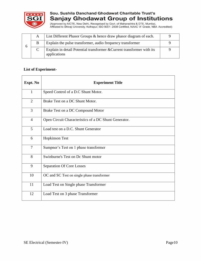
6
A List Different Phasor Groups & hence draw phasor diagram of each. 9
B Explain the pulse transformer, audio frequency transformer 9
C Explain in detail Potential transformer &Current transformer with its
applications
9
List of Experiment-
Expt. No
Experiment Title
1 Speed Control of a D.C Shunt Motor.
2 Brake Test on a DC Shunt Motor.
3 Brake Test on a DC Compound Motor
4 Open Circuit Characteristics of a DC Shunt Generator.
5 Load test on a D.C. Shunt Generator
6 Hopkinson Test
7 Sumpner’s Test on 1 phase transformer
8 Swinburne's Test on Dc Shunt motor
9 Separation Of Core Losses
10 OC and SC Test on single phase transformer
11 Load Test on Single phase Transformer
12 Load Test on 3 phase Transformer
SE Electrical (Semester-IV) Page11
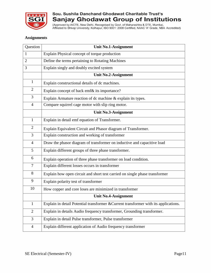
Assignments
Question Unit No.1-Assignment
1 Explain Physical concept of torque production
2 Define the terms pertaining to Rotating Machines
3 Explain singly and doubly excited system
Unit No.2-Assignment
1 Explain constructional details of dc machines.
2 Explain concept of back emf& its importance?
3 Explain Armature reaction of dc machine & explain its types.
4 Compare squirrel cage motor with slip ring motor.
Unit No.3-Assignment
1 Explain in detail emf equation of Transformer.
2 Explain Equivalent Circuit and Phasor diagram of Transformer.
3 Explain construction and working of transformer
4 Draw the phasor diagram of transformer on inductive and capacitive load
5 Explain different groups of three phase transformer.
6 Explain operation of three phase transformer on load condition.
7 Explain different losses occurs in transformer
8 Explain how open circuit and short test carried on single phase transformer
9 Explain polarity test of transformer
10 How copper and core loses are minimized in transformer
Unit No.4-Assignment
1 Explain in detail Potential transformer &Current transformer with its applications.
2 Explain in details Audio frequency transformer, Grounding transformer.
3 Explain in detail Pulse transformer, Pulse transformer
4 Explain different application of Audio frequency transformer
SE Electrical (Semester-IV) Page12
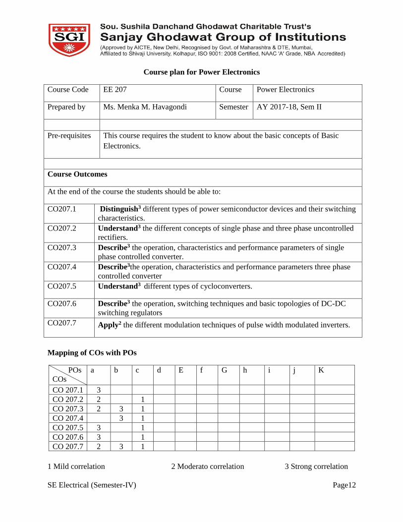
Course plan for Power Electronics
Course Code EE 207 Course Power Electronics
Prepared by Ms. Menka M. Havagondi Semester AY 2017-18, Sem II
Pre-requisites This course requires the student to know about the basic concepts of Basic
Electronics.
Course Outcomes
At the end of the course the students should be able to:
CO207.1 Distinguish3 different types of power semiconductor devices and their switching
characteristics.
CO207.2 Understand3 the different concepts of single phase and three phase uncontrolled
rectifiers.
CO207.3 Describe3 the operation, characteristics and performance parameters of single
phase controlled converter.
CO207.4 Describe3the operation, characteristics and performance parameters three phase
controlled converter
CO207.5 Understand3 different types of cycloconverters.
CO207.6 Describe3 the operation, switching techniques and basic topologies of DC-DC
switching regulators
CO207.7 Apply2 the different modulation techniques of pulse width modulated inverters.
Mapping of COs with POs
POs
COs
a b c d E f G h i j K
CO 207.1 3
CO 207.2 2 1
CO 207.3 2 3 1
CO 207.4 3 1
CO 207.5 3 1
CO 207.6 3 1
CO 207.7 2 3 1
1 Mild correlation 2 Moderato correlation 3 Strong correlation
SE Electrical (Semester-IV) Page13
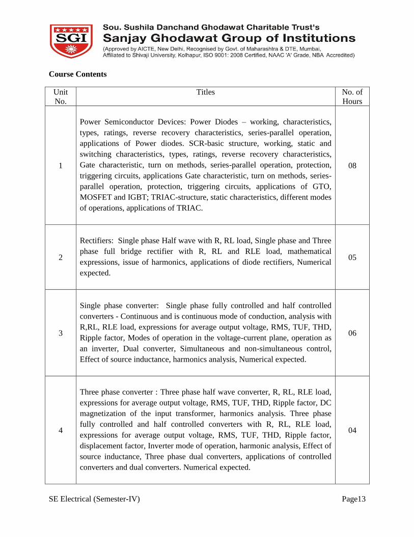
Course Contents
Unit
No.
Titles No. of
Hours
1
Power Semiconductor Devices: Power Diodes – working, characteristics,
types, ratings, reverse recovery characteristics, series-parallel operation,
applications of Power diodes. SCR-basic structure, working, static and
switching characteristics, types, ratings, reverse recovery characteristics,
Gate characteristic, turn on methods, series-parallel operation, protection,
triggering circuits, applications Gate characteristic, turn on methods, series-
parallel operation, protection, triggering circuits, applications of GTO,
MOSFET and IGBT; TRIAC-structure, static characteristics, different modes
of operations, applications of TRIAC.
08
2
Rectifiers: Single phase Half wave with R, RL load, Single phase and Three
phase full bridge rectifier with R, RL and RLE load, mathematical
expressions, issue of harmonics, applications of diode rectifiers, Numerical
expected.
05
3
Single phase converter: Single phase fully controlled and half controlled
converters - Continuous and is continuous mode of conduction, analysis with
R,RL, RLE load, expressions for average output voltage, RMS, TUF, THD,
Ripple factor, Modes of operation in the voltage-current plane, operation as
an inverter, Dual converter, Simultaneous and non-simultaneous control,
Effect of source inductance, harmonics analysis, Numerical expected.
06
4
Three phase converter : Three phase half wave converter, R, RL, RLE load,
expressions for average output voltage, RMS, TUF, THD, Ripple factor, DC
magnetization of the input transformer, harmonics analysis. Three phase
fully controlled and half controlled converters with R, RL, RLE load,
expressions for average output voltage, RMS, TUF, THD, Ripple factor,
displacement factor, Inverter mode of operation, harmonic analysis, Effect of
source inductance, Three phase dual converters, applications of controlled
converters and dual converters. Numerical expected.
04

SE Electrical (Semester-IV) Page14
5
Cyclo-converters: Single phase to single phase cycloconverter with R and
RL load, Three phase to Single phase cycloconverter, Three phase to three
phase 3 and 6 pulse converter, circulating and non-circulating mode,
applications of cycloconverters.
05
6
Chopper: Classification, Principle of working of Step-down Chopper, Step-
up Chopper, Analysis, and voltage control methods, Morgan Chopper, Jones
Chopper, multiphase choppers. Numericals expected.
05
7
Inverters: Voltage source inverters, Single phase and three-phase- six step
(120/180 degree mode of operation), thyristorised bridge circuits, output
waveforms for R and R-L loads, harmonic analysis, PWM techniques-
Single, Multiple and Sinusoidal PWM, applications of VSI, current Source
Inverter, ASCCSI, advantages, applications of CSI, Numericals expected.
05
Reference books:
Sr. No. Title of book Author Publisher/Edition Topics
1) Power electronics Dr. P.S. Bimbhara Khanna Publication 15th
edition, 2010. 1,2,3,4,5,6
2) Power Electronics
M.D. Singh K.B.
Khanchandani
Tata Mc-Graw-Hill New
Delhi,1998 4,5,6,7
3) Power Electronics M H Rashid Prentice hall of India 2nd
edition, New Delhi 1999. 3,4,5,6,7
4) Power electronics M.D. Singh and
K.B. Khanchandani
Tata Mc-Graw-Hill, New
Delhi, 1998. 5,6,7
Evaluation scheme:
Examination
Scheme
Theory Term Work POE Total
Max. Marks 100 25 50 175
Contact
Hours/ week
4 ------- 2 6

SE Electrical (Semester-IV) Page15
Scheme of marks
Unit No. Title Marks*
1 Power Semiconductor Devices 24
2 Rectifiers 8
3 Single phase converter 16
4 Three phase converter 24
5 Cyclo-converters 16
6 Chopper 24
7 Inverters 24
• Weightage may differ.
Course Unitization
CO Evaluation Remark
CO207.1 CAT 1 1 question on unit 1 and 2 with 15 marks each
CO207.2
CO207.3 CAT 2 1 question on unit 3 and 4 with 15 marks each
CO207.4
CO207.5
CAT 3 1 question on unit 5 ,6 & 7with 15 marks each CO207.6
CO 207.7
Unit wise Lesson Plan
Unit No Unit Title Planned Hrs.
01 Power Semiconductor Devices 08
Lesson schedule
Class
No.
Details to be covered
1 Importance of power electronics and Applications,
2 Power Diodes – working, characteristics, types, ratings, reverse recovery characteristics.
3 Series-parallel operation, applications of Power diodes.

SE Electrical (Semester-IV) Page16
4 Transistor, MOSFET, IGBT, Construction, working,
5 SCR-basic structure, working, static and switching characteristics,
6 Types, ratings, reverse recovery characteristics, Gate characteristic, turn on
methods.Numerical problems
7 Series-parallel operation, protection, triggering circuits, Applications of GTO, MOSFET
and IGBT
8 TRIAC-structure, static characteristics, different modes of operations, applications of
TRIAC
Review Questions
Q1 Draw V-I characteristics of triac. And explain working principle. CO 207.1
Q2 Draw V-I characteristics of SCR. And explain working principle CO 207.1
Q.3 Draw V-I characteristics of IGBT. And explain working principle.
CO 201.1
Q.4 Compare SCR, Power BJT, MOSFET and IGBT on the following basis,
i. Operating frequency
ii. Trigger circuit
iii. Drop
iv. Snubbers
v. V-I rating
CO 207.1
Unit No Unit Title Planned Hrs.
02 Rectifiers 5
Lesson schedule
Class
No.
Details to be covered
1 Single phase Half wave with R, RL load, RL and RLE load, mathematical expressions,
2 Single phase full bridge rectifier with R, RL and RLE load, mathematical expressions
tics
3 Three phase full bridge rectifier with R, RL and RLE load, Mathematical expressions
4 Issue of harmonics, applications of diode rectifiers
5 Numerical (1 phase, 3 phase Rectifier).
Review Questions
Q1 Describe a 3 phase full wave diode bridge rectifier with a circuit diagram
and relevant waveform for load R. Hence derive expression of average
CO 207.2

SE Electrical (Semester-IV) Page17
and RMS value of output voltage and obtain there from VRF, FF,
rectifier efficiency and TUF.
Q2 Explain the operation of 1 phase FWR with Bridge connection, and
waveforms. Hence derive expression of average and RMS value of
output voltage.
CO 207.2
Q3 Explain the operation of 1 phase half wave rectifier with R-L load. Draw
the relevant waveforms.
CO 207.2
Q4 Draw the circuit diagram for single phase, full bridge diode rectifier with
resistive load. Draw the input and output voltage and current waveforms.
Derive the expression for output DC voltage, output RMS voltage and
form factor.
CO 207.2
Unit No Unit Title Planned Hrs.
03 Single Phase Converter 06
Lesson schedule
Class
No.
Details to be covered
1 Single phase fully controlled and half controlled converters Single phase full bridge
rectifier with R, RL and RLE load, mathematical expressionstics,
2 Single phase fully controlled and half controlled converters,
3 Continuous and is continuous mode of conduction, analysis with R, RL, RLE load,
4 Expressions for average output voltage, RMS, TUF, THD, Ripple factor,
5 Modes of operation in the voltage-current plane, operation as an inverter, Dual
converter,
6 Simultaneous and Non-simultaneous control, Effect of source inductance, harmonics
analysis, Numerical.
Review Questions
Q1
Describe the working of 1-phase fully controlled bridge converter in the
following two modes:
a. Rectifying mode
b. Inversion mode.
Also sketch the following waveforms for α=45° and α=120°
i. Load voltage.
ii. Load current
iii. SCR current and voltage.
iv. Supply voltage and current.
CO 207.3
Q2 Single phase full converter bridge is connected to RLE load. The source
voltage is 230V, 50Hz. The average load current of 10A is continuous
CO 207.3
SE Electrical (Semester-IV) Page18
over the working range. For R=0.4Ω and L= 2mH. Compute
i. Firing angle delay for= 120V
ii. Firing angle delay for= -120V
iii. Indicate which source is delivering power to load in i) & ii)
iv. If output current is assumed constant. Find the input power factor
for both i) and ii).
Unit No. Unit Title Planned Hrs
04 Three Phase Converter 04
Lesson schedule
Class
No. Details to be covered
1 Three phase half wave converter, R, RL, RLE load, Numericals,
2 Expressions for average output voltage, RMS, TUF, THD, Ripple factor, DC
magnetization of the input transformer, harmonics analysis,
3 Three phase fully controlled and half controlled converters with R, RL, RLE load,
Numericals,
4 Expressions for average output voltage, RMS, TUF, THD, Ripple factor, displacement
factor.
Review Questions
1 Describe the working of 3 phase semi converter with feeding to R load.
Derive expression of average and RMS value of output voltage.
CO 207.4
2 Draw circuit diagram of single phase circulating current type Dual
converter. Explain operation with the help input ac voltage waveform,
output DC voltage waveform of the two converters and the waveform of
inductor voltage. Explain the need of the inductor
CO 207.4
3 Draw circuit diagram of 3 phase circulating current type Dual converter.
Explain operation with the help input ac voltage waveform, output DC
voltage waveform of the two converters and the waveform of inductor
voltage.
CO 207.4
Unit No. Unit Title
Planned Hrs.
05 Cycloconverters 05
Lesson schedule
Class
No. Details to be covered
1,2 Single phase to single phase cyclo-converter with R and RL load, circulating and non-
circulating mode, applications of cyclo-converters,
3,4 Three phase to Single phase cyclo-converter,

SE Electrical (Semester-IV) Page19
5 Three phase to three phase 3 and 6 pulse converter.
Review Questions
1 Explain the principle and operation of 1 phase Cycloconverter. CO 207.5
2 Explain the principle and operation of 3 phaseCycloconverter. CO 207.5
Unit No Unit Title Planned Hrs.
06 Choppers 05
Lesson schedule
Class
No. Details to be covered
1 Classification, Principle of working of Step-down Chopper.
2 Step-up Chopper, Analysis
3 Voltage control methods, Morgan Chopper
4 Jones Chopper, multiphase choppers,
5 Numericals
Review Questions
1 Differentiate between constant frequency and variable frequency control. CO 207.6
2 Discuss the principle of operation of DC-DC step down chopper with
suitable waveforms. Derive the expression for its average dc voltage.
CO 207.6
Unit No Unit Title Planned Hrs.
07 Inverters 05
Lesson schedule
Class
No. Details to be covered
1 Single phase Voltage source inverters,
2 Three-phase- six step (120/180 mode of operation),
3 Thyristorised bridge circuits, Output waveforms for R and R-L loads, Harmonic
analysis,
4 PWM techniques-Single, Multiple and Sinusoidal PWM,
5 Applications of VSI, current Source Inverter, ASCCSI, Advantages, Applications of
CSI. Numericals.

SE Electrical (Semester-IV) Page20
Review Questions
1 What is PWM? Explain the various techniques involved in it. CO 207.7
2 Explain in detail the 120 mode and 180 mode operation of inverter in
detail.
CO 207.7
3 What with neat diagram and waveform the series resonant inverter. CO 207.7
Model Question Paper
Course Title
Duration Marks
POWER ELECTRONICS
3 Hours 100
Instructions:
1] Attempt any two subquestions from each main question.
2] Figure to right indicates full marks.
3] Assume necessary data if required.
1
a Draw and explain in detail static V-I characteristic of SCR by
considering different mode of operation. 8
b
The voltage rating in particular circuit is 3.2kV. SCRs with voltage
rating of 60V are available. Calculate the number of SCRs required to
be connected in series. Also design the state equalizing circuit for the
above series connection if maximum blocking current of the SCRs at
the rated voltage is 6mA.
8
c
Single phase full converter bridge is connected to RLE load. The
source voltage is 230V, 50Hz. The average load current of 10A is
continuous over the working range. For R=0.4Ω and L= 2mH.
Compute
i. Firing angle delay for= 120V
ii. Firing angle delay for= -120V
iii. Indicate which source is delivering power to load in i) & ii)
iv. If output current is assumed constant. Find the input power
factor for both i) and ii).
8
2
a
Draw the circuit diagram of single phase half-wave diode rectifier
with freewheeling diode and R-L load. Explain the circuit operation.
Draw the waveforms of input and output voltage and current assuming
load current has no ripple. Derive the expressions for output DC
voltage.
8
b Draw and explain reverse recovery characteristics of power diodes.
Explain the terms: 8

SE Electrical (Semester-IV) Page21
1. Reverse recovery time trr
2. Peak reverse current Irr.
3. Reverse recovery charge Qrr.
c Discuss the principle of operation of DC-DC step down chopper with
suitable waveforms. Derive the expression for its average dc voltage 8
3
a
Describe the working of 1 phase fully controlled bridge converter in
the rectifier mode. And derive the rectification mode. derive
expression of average and RMS value of output voltage
9
b
Describe the working of 1 phase half wave controlled bridge converter
with feeding to R load. Derive expression of average and RMS value
of output voltage
9
c
Describe the working of 1-phase fully controlled bridge converter in
the following two modes:
a. Rectifying mode
b. Inversion mode.
9
4
a Describe the working of 3 phase semi converter with feeding to R
load. Derive expression of average and RMS value of output voltage 8
b
Draw circuit diagram of 3 phase circulating current type Dual
converter. Explain operation with the help input ac voltage waveform,
output DC voltage waveform of the two converters and the waveform
of inductor voltage.
8
c Explain with neat diagram and waveforms the series resonant inverter.
5
a
Explain the working of step-down chopper with neat diagram. Derive
an expression for average output voltage and rms output voltage. Draw
the graphs of average output voltage and rms output voltage as a
function of duty cycle.
9
b Explain Morgan’s chopper with neat circuit diagram and waveforms. 9
c Discuss the working of three phase 120° mode operation of voltage
source inverter with circuit diagram and waveforms. 9
6
a List various PWM techniques. Explain with neat waveforms
sinusoidal pulse width modulation. 8
b Explain single phase current source inverter with diagram and
waveforms. 8
c Explain with neat diagram and working of three auto sequential
current source inverter. 8

SE Electrical (Semester-IV) Page22
List of Experiment-
Expt. No Experiment Title
1 SCR/TRIC/ DIAC/ MOSFET/IGBT Characteristics.
2 Triggering circuits/phase control.
3 Single phase FW bridge converter feeding DC motor.
4 Three Phase Converter (HW and FW bridge).
5 Dual Converter.
6 Cycloconverters feeding Resistive load.
7 Jones/ Morgan Chopper.
8 Single phase / three phase Inverter with Resistive/Induction Motor load.
9 Simulation of Converter / Chopper using SPICE/MATLAB.
10 Simulation of PWM Inverter using SPICE/MATLAB.
Assignments
Question Unit No.1 Assignment
1 Explain the principle and operation of 1 phase Cycloconverter.
2 Explain the principle and operation of 3 phaseCycloconverter.
3 Describe the basic principle of 1phase to 1phase Cycloconverter for both continuous
and discontinuous conductions for a bridge type Cycloconverter.
4 Mark the conditions of various SCRs also Explain the operation of 4-quadrant
chopper
5 Discuss the principle of operation of DC-DC step down chopper with suitable
waveforms. Derive the expression for its average dc voltage.
Unit No.2 - Assignment
1 Explain the operation of 4-quadrant chopper.
2 Discuss the principle of operation of DC-DC step down chopper with suitable
waveforms
3 Explain the operation of Jone’s and Morgan’s chopper
4 Explain the operation of Jone’s and Morgan’s chopper

SE Electrical (Semester-IV) Page23
Unit No.3-Assignment
1 Explain in detail the 1200 mode and 1800 mode operation of inverter in detail.
2 What is PWM? Explain the various techniques involved in it.
3 Compare between VSI and CSI in detail.
Unit No.4-Assignment
1 Draw and explain in detail static V-I characteristic of SCR by considering different
mode of operation.
2 The voltage rating in particular circuit is 3.2kV. SCRs with voltage rating of 60V are
available. Calculate the number of SCRs required to be connected in series. Also
design the state equalizing circuit for the above series connection if maximum
blocking current of the SCRs at the rated voltage is 6mA.
3 Draw and explain reverse recovery characteristics of power diodes. Explain the
terms:
1. Reverse recovery time trr
2. Peak reverse current Irr.
3. Reverse recovery charge Qrr.
Unit No.5 -Assignment
1 Single phase full converter bridge is connected to RLE load. The source voltage is
230V, 50Hz. The average load current of 10A is continuous over the working range.
For R=0.4Ω and L= 2mH. Compute
i. Firing angle delay for= 120V
ii. Firing angle delay for= -120V
2 Describe a 3 phase full wave diode bridge rectifier with a circuit diagram and
relevant waveform for load R. Hence derive expression of average and RMS value
of output voltage and obtain there from VRF, FF, rectifier efficiency and TUF.
3 Explain cold rolling theories and hot rolling theories in brief.
Unit No.6 -Assignment
1 Explain principle of working of step down chopper with circuit diagram and
waveforms.
SE Electrical (Semester-IV) Page24
2 Explain Johnes chopper
Unit No.7 -Assignment
1 Explain 3 phase bridge inverter with 120 degree mode of operation.
2 Discuss the PWM techniques used in inverter circuits.

SE Electrical (Semester-IV) Page25
Course plan for Power System-I
Course Code EE 208 Course Power System-I
Prepared by Mr.Devendra Gowda Semester AY 2017-18, Sem IV
Pre-requisites Student should have good knowledge of electrical parameter and measuring
equipments.
Course Outcomes
At the end of the course the students should be able to:
CO208.1 Explain2 the generation of Electric Energy by different sources.
CO208.2 Describe1 the basic structure of power system and its components.
CO208.3 Explain2 Distribution system with classification.
CO208.4 Discuss2 and solve3 the problems of the overhead transmission line and
Underground cables.
CO208.5 Describe1 the importance and equipments used to improve the power factor.
CO208.6 Explain2 and solve3 the problems of Economic Aspects of Power Generation.
Mapping of COs with POs
Pos
COs a b c d e f g h i j k
CO208.1 3
CO208.2 3
CO208.3 3
CO208.4 3 2
CO208.5 3
CO208.6 2 3
1 Mild correlation 2 Moderato correlation 3 Strong correlation

SE Electrical (Semester-IV) Page26
Course Contents
Unit
No.
Title
No. of
Hrs.
1 Generation of Electric Energy and Power System Components
Schematic/ Block diagram of Hydro power plant, Thermal power plant, Nuclear
power plant and Diesel power plants and their working. Basic structure of an AC
power system, Distribution voltage level, Sub-transmission level, Single line
diagram. Brief Description of Power system elements such as Synchronous
Machine, Transformer, Bus bar, Circuit Breaker, isolator, CT, PT.
8
2 Distribution Systems
Classification of Distribution Systems, AC Distribution- Primary and Secondary
Distribution systems, Overhead and Underground systems, Connection scheme of
distribution system, Radial system, Ring main system, Interconnected systems,
feeders and distributors, AC distribution calculations.
10
3 Overhead Transmission Lines and Underground Cables
Types of conductors- Hard drawn copper, hard drawn aluminum, steel cored
aluminum, ACSR, SSC,AAC, Smooth Body ACSR, Expanded ACSR, ACAR,
bundled conductor, Resistance,inductance and capacitance for single and double
circuit lines, skin effect and proximity effect. Main components of over head
lines, conductor materials, line supports, Types of line supports, insulators, types
of insulators, potential distribution over suspension insulators, string efficiency,
methods of improving string efficiency. Corona, factors affecting corona,
important terms,advantages and disadvantages of corona, methods of reducing
corona effect, sag in over head lines and sag calculations. Construction and
classification of cables for single and three phase service, Methods of laying
underground cables.
6
4
Characteristics and Performance of Transmission Line:
Short, medium and long lines, Voltages and currents at sending and receiving end
of line, ABCD constants, Sending end and receiving power circle diagrams,
universal power circle diagram, voltage and current waves, surge impedance
loading of transmission line, Complex Power flow through transmission line,
Power transmission capability, Ferranti effect, tuned power lines, methods of
voltage control, voltage regulators, tap changing transformers, booster
transformers, synchronous phase modifiers,.
10
5 Power Factor Improvement:
Causes and disadvantages of Low power factor, power factor improvement
Equipments-using Static capacitors, synchronous condensers, phase advancers,
Calculation of Power factor correction; Importance of power factor improvement,
Most economical power factor derivation. .
8

SE Electrical (Semester-IV) Page27
6 Economic Aspects of Power Generation
Load curve, load duration and integrated load duration curves-load, demand,
diversity, capacity, Utilization and plant use factors- Numerical Problems. Costs
of Generation and their division into Fixed, Semi-fixed and Running Costs.
Desirable Characteristics of a Tariff Method.-Tariff Methods: Flat Rate, Block-
Rate, two-part, three –part, and power factor tariff methods
Note: Numericals are expected on units
6
Reference books:
Sr. No. Title of Book Author Publisher/Edition
1) Elements of power station design M.V. Deshpande Tata McGraw Hill
2) Electrical Power Systems. C.L.Wadhawa New age International
Limited
3) Power plant Engineering- steam &
nuclear
P. K. Nag, Tata McGraw Hill
4) Power plant Engineering Fredrick T. Morse East west press private
Ltd
5) Power plant Engineering Mahesh Varma Metrolitan book Co Pvt
Ltd
6) Direct Energy Conversion George W. Sutten Prentice Hall
International.
Evaluation scheme:
Examination
Scheme
Theory Term Work Practical Total
Max. Marks 100 50 150
Contact
Hours/ week
4 02 06
Scheme of Marks
Section Unit No. Title Marks
I 1 Generation of Electric Energy and Power System
Components
16

SE Electrical (Semester-IV) Page28
2 Distribution Systems
16
3 Overhead Transmission Lines and Underground Cables
18
II
4 Characteristics and Performance of Transmission Line:
16
5 Power Factor Improvement:
16
6 Economic Aspects of Power Generation
18
Course Unitization
CO Evaluation Remark
CO208.1 CAT 1 1 question on unit 1 and 2 with 15 marks each
CO208.2
CO208.3 CAT 2 1 question on unit 3 and 4 with 15 marks each
CO208.4
CO208.5 CAT 3 1 question on unit 5 and 6 with 15 marks each
C0208.6
Unit wise lesson plan
Unit No
Unit Title Planned Hrs.
01 Generation of Electric Energy and Power System
Components
08
Lesson schedule
Class
No.
Details to be covered
1 Schematic/ Block diagram of Hydro power plant
2 Schematic/ Block diagram Thermal power plant
3 Schematic/ Block diagram Nuclear power plant
SE Electrical (Semester-IV) Page29
4 Schematic/ Block diagram Diesel power plan.
5 Voltage level, Sub-transmission level, Single line diagram.
6 Brief Description of Power system elements such as Synchronous Machine
7 Transformer, Bus bar, Circuit Breaker.
8 Isolator, CT, PT.
Review Questions
Q1 Explain Schematic/ Block diagram Hydropower plant in detail. CO 208.1
Q2 Explain Schematic/ Block diagram Nuclear power plant. CO 208.1
Unit No
Unit Title Planned Hrs.
2 Distribution Systems 6
Lesson schedule
Class
No.
Details to be covered
1 Classification of Distribution Systems, AC Distribution- Primary and Secondary
Distribution systems.
2 Connection scheme of distribution system, Radial system.
3 Systems Ring main system, Interconnected systems.
4 Overhead and Underground.
5 Feeders and distributors.
6 AC distribution calculations.
Review Questions
Q1 Explain the differences between ring type and radial distribution system CO 208.2
Q2 Explain different types of Underground cables CO 208.2
Unit
No
3 Unit Title Overhead Transmission Lines and
Underground Cables
Planned
Hrs.
10
Lesson schedule
Class
No.
Details to be covered
1 Types of conductors- Hard drawn copper, hard drawn aluminum, steel cored
aluminum, ACSR, SSC,AAC.

SE Electrical (Semester-IV) Page30
2 Smooth Body ACSR, Expanded ACSR, ACAR, bundled conductor.
3 Resistance, inductance.
4 Capacitance for single and double circuit lines.
5 Skin effect and proximity effect. Main components of over head lines.
6 Conductor materials, line supports, Types of line supports.
7 And insulators, types of insulators, potential distribution over suspension insulators.
8 String efficiency, methods of improving string efficiency.
9 Corona, factors affecting corona, important terms, advantages and disadvantages of
corona, methods of reducing corona effect.
10 Sag in over head lines and sag calculations. Construction and classification of cables
for single and three phase service. Methods of laying underground cables.
Review Questions
Q1 Skin effect and proximity effect CO 208.3
Q2 Explain types of insulators CO 208.3
Unit
No Unit Title
Planned Hrs.
4 Characteristics and Performance of Transmission Line 10
Lesson schedule
Class
No.
Details to be covered
1 Short, medium and long lines, Voltages and currents at sending and receiving end of
line.
2 ABCD constants.
3 Sending end and receiving power circle diagrams.
4 Universal power circle diagram.
5 Voltage and current waves, surge impedance loading of transmission line.
6 Complex Power flow through transmission line.
7 Power transmission capability, Ferranti effect.
8 tuned power lines, methods of voltage control, voltage regulators.
9 tap changing transformers, booster transformers.
SE Electrical (Semester-IV) Page31
10 Synchronous phase modifiers
Review Questions
1 Derive ABCD Constants of transmission line. CO 208.4
2 Explain tap changing transformers, booster transformers.
CO 208.4
Unit
No
5 Unit Title Power Factor Improvement
Planned
Hrs.
8
Lesson schedule
Class
No.
Details to be covered
1 Causes and disadvantages of Low power factor.
2 Power factor improvement Equipments-using Static capacitors.
3 Synchronous condensers, phase advancers.
4 Calculation of Power factor correction.
5 Problems on power factor correction.
6 Importance of power factor improvement.
7 Most economical power factor derivation.
8 Problems on Most economical power factor derivation.
Review Questions
1 Causes and disadvantages of Low power factor. CO 208.5
2 Derive equation for Most economical power factor derivation. CO 208.5
Unit No
Unit Title Planned Hrs.
6 Economic Aspects of Power Generation 6
Lesson schedule
Class
No.
Details to be covered
1 Load curve, load duration and integrated load duration curves.
2 load, demand, diversity, capacity.
3 Utilization and plant use factors- Numerical Problems.
SE Electrical (Semester-IV) Page32
4 Costs of Generation and their division into Fixed, Semi-fixed and Running Costs.
5 Desirable Characteristics of a Tariff Method.-Tariff Methods: Flat Rate, Block-Rate,
two-part, three –part, and power factor tariff methods.
6 Numerical are expected on units
Review Questions
1 Explain Load curve, load duration and integrated load duration curves. CO 208.6
2 Explain load, demand, diversity, capacity. CO 208.6
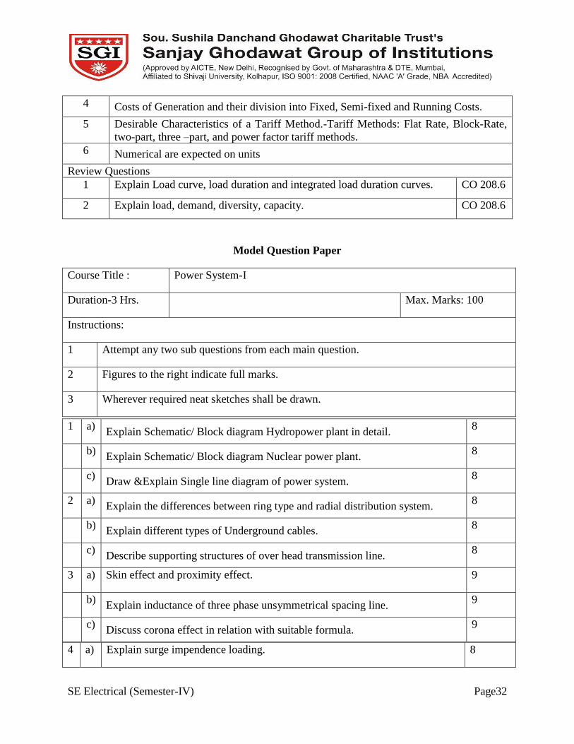
Model Question Paper
Course Title : Power System-I
Duration-3 Hrs. Max. Marks: 100
Instructions:
1 Attempt any two sub questions from each main question.
2 Figures to the right indicate full marks.
3 Wherever required neat sketches shall be drawn.
4 a) Explain surge impendence loading. 8
1 a) Explain Schematic/ Block diagram Hydropower plant in detail.
8
b) Explain Schematic/ Block diagram Nuclear power plant.
8
c) Draw &Explain Single line diagram of power system.
8
2 a) Explain the differences between ring type and radial distribution system.
8
b) Explain different types of Underground cables.
8
c) Describe supporting structures of over head transmission line.
8
3 a) Skin effect and proximity effect. 9
b) Explain inductance of three phase unsymmetrical spacing line.
9
c) Discuss corona effect in relation with suitable formula.
9

SE Electrical (Semester-IV) Page33
b) Explain in detail of Ferranti effect phenomenon. 8
c) Derive the expression for sending end and receiving power flow through
transmission line
8
5 a) Causes, Advantages & disadvantages of Low power factor. 8
b) Derive equation for Most economical power factor derivation. 8
c) Explain the methods of power factor improvement. 8
6 a) Explain Load curve, load duration and integrated load duration curves. 9
b) Explain any one two types of tariff methods. 9
c) Define: Load factor, Diversity factor, plant capacity factor. 9
Lab Plan
Expt. No Experiment Title
1 Design of thermal power plant
2 Design of Nuclear power plant
3 Design of Hydro power plant
4 One line diagram of power system using Matlab /Simulink
5 Transmission line parameter effects using Matlab /Simulink
6 Design power transmission line sag and swell phenomena
7 Draw the substation diagram using software
8 Design the underground cable using software
Assignments
Question
No.
Unit No.1 -Assignment
1 Draw &Explain Schematic/ Block diagram of Hydro power plant
2 Draw &Explain Schematic/ Block diagram Thermal power plant
3 Draw &Explain Schematic/ Block diagram Nuclear power plant
4 Draw &Explain Single line diagram of power system
Unit No.2-Assignment
1 Describe supporting structures of over head transmission line
SE Electrical (Semester-IV) Page34
2 Distinguish connection schemes of distribution system
3 Describe the construction of underground cables
Unit No.3-Assignment
1 Discuss corona effect in relation with suitable formula
2 Explain inductance of three phase unsymmetrical spacing line
3 Explain capacitance grading and inter sheath grading and also difference between
them.
Unit No.4-Assignment
1 Explain surge impendence loading
2 Derive the expression for sending end and receiving power flow through
transmission line
3 Explain in detail of Ferranti effect phenomenon.
Unit No.5-Assignment
1 Explain Causes and disadvantages & Disadvantages of Low power factor
2 Explain the methods of power factor improvement
3 Derive equation for Most economical power factor derivation
Unit No.6-Assignment
1 Define: Load factor ,Diversity factor, plant capacity factor
2 Explain different types of tariff methods
3 Explain Load curve, load duration and integrated load duration curves

SE Electrical (Semester-IV) Page35
Course plan for Network Analysis and Synthesis
Course Code ELE 209 Course Title Network Analysis and Synthesis
Prepared by Mr.PatilUday T. Semester AY 2017-18, Sem II
Prerequisites The student should know about the basic techniques of DC circuit analysis.
Course Outcomes
At the end of the course the students should able to:
CO209.1 Describe1 network elements, basic techniques to evaluate ac circuits.
CO209.2 Apply3 network theorems for analysis of ac circuits.
CO209.3 Understand2transform analysis techniques for ac circuits.
CO209.4 Define1 network functions and two port network.
CO209.5 Understand2network synthesis techniques.
CO209.6 Analyse4&synthesize5 various types of filters.
Mapping of COs with POs
POs
Cos
a b c d e f g h i j k
CO209.1 2 1
CO209.2 2 3
CO209.3 1 3
CO209.4 2 1
CO209.5 2 2
CO209.6 2 1
1 Mild correlation 2 Moderato correlation 3 Strong correlation
Course Contents
Unit No. Network Analysis and Synthesis
No. of
Hours
SE Electrical (Semester-IV) Page36
1. INTRODUCTION: Network elements, Initial and final conditions, Step,
Impulse and Ramp Functions, solution of differential equation, concept
of impedance and admittance, , Node and Mesh analysis for ac circuits,
8
2. NETWORK THEOREMS: Superposition Theorem, Norton’s Theorem,
Thevenin’s Theorem, Maximum Power Transfer Theorem, Reciprocity
Theorem, Millman’s Theorem
6
3. TRANSFORM ANALYSIS: Introduction, properties of Laplace
Transform, The inverse Laplace Transform, Application to
integrodifferntial equations, Circuit Element Model, Application of
Laplace Transform to Electric Circuits, Fourier Transform, Properties of
Fourier Transform, and Circuit Applications.
8
4. TWO PORT NETWORK & NETWORK FUNCTIONS:
Two port network: Open circuit impedance ( Z ) parameters, Short
circuit admittance (Y) parameters, Hybrid ( H ) parameter, Transmission
parameters(ABCD), Interrelation of different parameters,
Interconnections of two port network. Network Functions: Network
functions for one port & two port networks, Driving point impedance
and admittance of one port network, Driving point impedance,
admittance & different transfer function of two port network Concept of
complex frequency, significance of poles & zeros, pole zero diagram.
8
5. NETWORK SYNTHESIS: Introduction, Hurwitz Polynomials, Positive
Real Function, Synthesis of Driving point Immitance Function,
Synthesis of Driving point Impedance Function, LC Network, Two
Terminal R-L Network, Two Terminal R-C Network,
8
6. FILTER SYNTHESIS: Introduction, Image Parameters, Characteristics
Impedance, Basic Types of Filters,Filter Fundamentals, Passive Filters,
Composite Filters,
Limitation of Passive Filters, Design of Constant K and M derived
Filters
6

SE Electrical (Semester-IV) Page37
Reference Books:
Sr. No. Title of Book Author Publisher/Edition Topics
1) “Network Analysis and
Synthesis”
Franklin F Kuo John Wiely Sons 1,2,3,4
2) “Network Analysis”, M.E. Van
Valkenburg,
Prentice Hall of
India
3,4,5,6
3) “Electric Circuits”, TMH C. K. Alexander McGraw hill 1,2,3,4
4) “Networks and Systems” D. Roy Choudhary, New age, 4,5,6,
Examination Scheme
Examination
Scheme
Theory Term Work POE Total
Max. Marks 100 ---- ------ 100
Contact
Hours/ week
3 --- ------ 3
Scheme of Marks
Unit No. Title Marks
1 Introduction. 16
2 Network Theorems. 24
3 Transform Analysis. 26
4 Two Port Network & Network Functions. 24
5 Network Synthesis. 24
6 Filter Synthesis. 18
Course Unitization
CO Evaluation Remark
CO209.1 CAT 1 1 question on unit 1 and 2 with 15 marks each.
CO209.2

SE Electrical (Semester-IV) Page38
CO209.3 CAT 2 1 question on unit 3 and 4 with 15 marks each.
CO209.4
CO209.5 CAT 3 1 question on unit 5 and 6 with 15 marks each.
CO209.6
Unit wise Lesson Plan
Unit No Unit Title Planned Hrs.
1 INTRODUCTION. 8
Lesson schedule
Class
No.
Details to be covered
1 Network elements, Initial and final conditions,
2 Step, Impulse and Ramp Functions, solution of differential equation,
3 concept of impedance and admittance,
4 concept of impedance and admittance,
5 Node and Mesh analysis for ac circuits,
6 Node and Mesh analysis for ac circuits,
7 Node and Mesh analysis for ac circuits,
8 Node and Mesh analysis for ac circuits,
Review Questions:
1 Find mesh currents i1 and i 2
CO209.1
2 Calculate I0 shown in the figure
CO209.1

SE Electrical (Semester-IV) Page39
Unit No
Unit Title Planned Hrs.
2 NETWORK THEOREMS: 6
Lesson schedule
Class
No.
Details to be covered
1 Superposition Theorem.
2 Norton’s Theorem.
3 Thevenin’s Theorem.
4 Maximum Power Transfer Theorem.
5 Reciprocity Theorem.
6 Millman’s Theorem.
Review Questions:
1 Apply reciprocity theorem for the branches ab & cd.
CO209.2
2 Calculate I0 shown in the figure by superposition theorem.
CO209.2
3 Find thevenins equivalent ckt across terminal ab. CO209.2
SE Electrical (Semester-IV) Page40
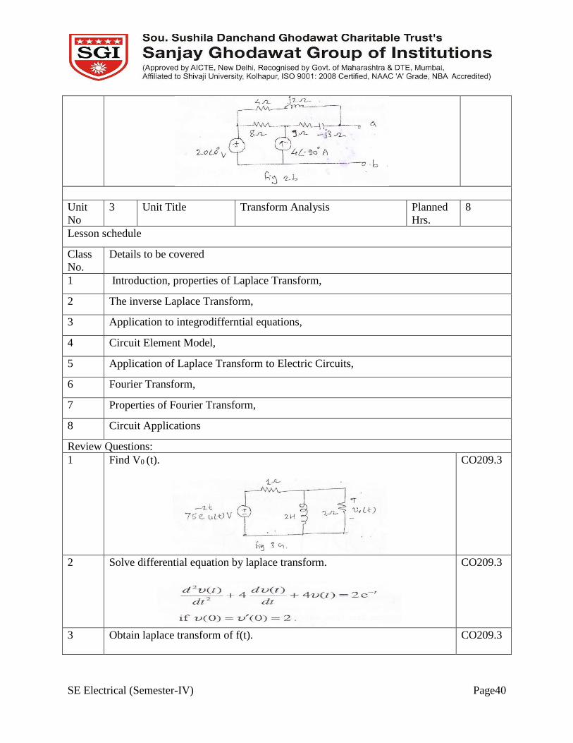
Unit
No
3 Unit Title Transform Analysis Planned
Hrs.
8
Lesson schedule
Class
No.
Details to be covered
1 Introduction, properties of Laplace Transform,
2 The inverse Laplace Transform,
3 Application to integrodifferntial equations,
4 Circuit Element Model,
5 Application of Laplace Transform to Electric Circuits,
6 Fourier Transform,
7 Properties of Fourier Transform,
8 Circuit Applications
Review Questions:
1 Find V0 (t).
CO209.3
2 Solve differential equation by laplace transform.
CO209.3
3 Obtain laplace transform of f(t).
CO209.3

SE Electrical (Semester-IV) Page41
4 Obtain fourier transform of f(t).
CO209.3
Unit
No
4 Unit Title Two Port Network & Network
Functions:
Planned
Hrs.
8
Lesson schedule
Class
No.
Details to be covered
1 Two port network: Open circuit impedance ( Z ) parameters, Short circuit admittance
(Y) parameters,
2 Hybrid ( H ) parameter, Transmission parameters(ABCD),
3 Interrelation of different parameters,
4 Interconnections of two port network
5 Network Functions: Network functions for one port & two port networks, Driving
point impedance and admittance of one port network,
6 Driving point impedance,
7 admittance & different transfer function of two port network
8 Concept of complex frequency, significance of poles & zeros, pole zero diagrams.
Review Questions
1 Find impedance parameters.
CO209.4
2 Find y parameters.
CO209.4

SE Electrical (Semester-IV) Page42
3 Find driving point impedance, transfer impedance function,voltage transfer
fuction.
CO209.4
Unit
No
5 Unit Title NETWORK SYNTHESIS Planned
Hrs.
8
Lesson schedule
Class
No.
Details to be covered
1 Introduction
2 Hurwitz Polynomials,
3 Positive Real Function,
4 Synthesis of Driving point Immitance Function,
5 Synthesis of Driving point Impedance Function,
6 LC Network,
7 Two Terminal R-L Network,
8 Two Terminal R-C Network,
Review Questions
1 State the conditions to find out positive real function. CO209.5
2 Check following polynomials are hurwitz or not.
CO209.5
Unit
No
6 Unit Title Filter Synthesis Planned
Hrs.
6
Lesson schedule
Class Details to be covered

SE Electrical (Semester-IV) Page43
No.
1 Introduction, Image Parameters, Characteristics Impedance,
2 Basic Types of Filters, Filter Fundamentals,
3 Passive Filters, Composite Filters,
4 Limitation of Passive Filters,
5 Design of Constant K and M derived Filters
Review Questions
1 Explain classification of filter in detail. CO209.6
2 Design a constant k low pass filter having fc=2 kHz and design impedance
R0 = 600 ohm also find value of attenuation at 4 kHz.
CO209.6
Model Question Paper
Course Title : Network Analysis and Synthesis
Duration 3 Hours Marks:
100
Instructions:
1] Attempt any two questions from each main question.
2] Figure to right indicates full marks.
3] Assume necessary data if required.
1 a Find mesh currents.
8
b Apply reciprocity theorem for the branches ab & cd.
8
c Check following polynomials are hurwitz or not. 8
SE Electrical (Semester-IV) Page44
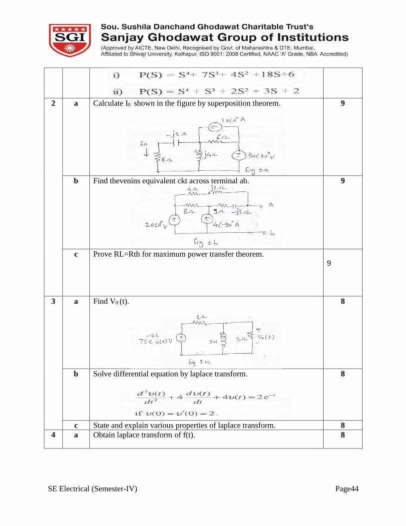
2 a Calculate I0 shown in the figure by superposition theorem.
9
b Find thevenins equivalent ckt across terminal ab.
9
c Prove RL=Rth for maximum power transfer theorem.
9
3 a Find V0 (t).
8
b Solve differential equation by laplace transform.
8
c State and explain various properties of laplace transform. 8
4 a Obtain laplace transform of f(t).
8

SE Electrical (Semester-IV) Page45
b
Obtain fourier transform of f(t).
8
c Find impedance parameters.
8
5 a State the conditions to find out positive real function. 8
b Find y parameters.
8
c Express Z parameters in terms of Y parameters. 8
6 a Find driving point impedance, transfer impedance function,voltage
transfer fuction.
9
b Explain classification of filter in detail. 9
c Design a constant k low pass filter having fc=2 kHz and design
impedance R0 = 600 ohm also find value of attenuation at 4 kHz.
9
SE Electrical (Semester-IV) Page46
Assignments
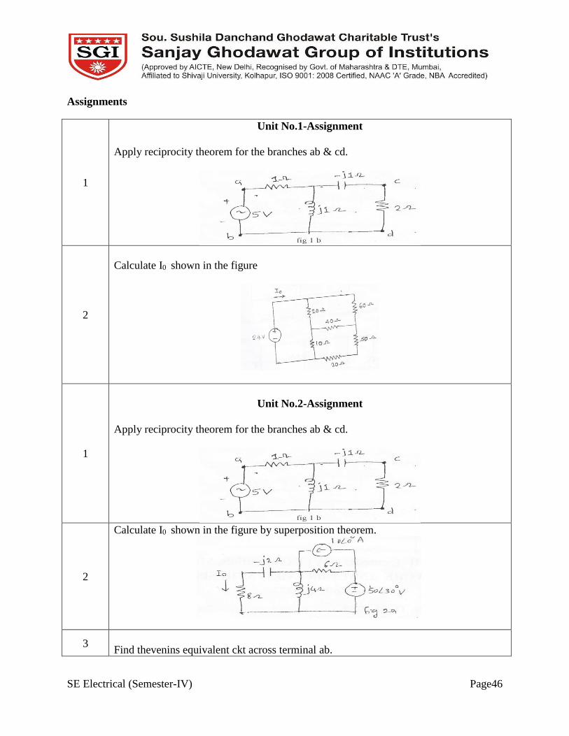
1
Unit No.1-Assignment
Apply reciprocity theorem for the branches ab & cd.
2
Calculate I0 shown in the figure
1
Unit No.2-Assignment
Apply reciprocity theorem for the branches ab & cd.
2
Calculate I0 shown in the figure by superposition theorem.
3
Find thevenins equivalent ckt across terminal ab.

SE Electrical (Semester-IV) Page47
1
Unit No.3-Assignment
Find V0 (t).
2
Solve differential equation by laplace transform.
3
Obtain laplace transform of f(t).
1
Unit No.4-Assignment
Obtain fourier transform of f(t).

SE Electrical (Semester-IV) Page48
2
Find impedance parameters.
3
Find y parameters.
Unit No.5-Assignment
1 What is mean by Hurwitz polynomials, explain its properties.
2 Explain PR function with example.
Unit No.6-Assignment
1 Explain classification of filter in detail.
2 Design a constant k low pass filter having fc=2 kHz and design impedance R0 = 600
ohm also find value of attenuation at 4 kHz.

SE Electrical (Semester-IV) Page49
Course plan for Control System-I
Course Code CE 210 Course Control System-I
Prepared by Mr. A.N.Shinde
Mr.Pankaj M. Maskar
Semester AY 2017-18, Sem II
Pre-requisites This course requires the student to know about the basic concepts of different
mathematical signals and their Laplace Transform.
Course Outcomes
At the end of the course the students should be able to:
CO210.1 Develop2themodel ofdifferent mechanical and electrical systems.
CO210.2 Analyze3response of first and second order systems.
CO210.3 Explain2the construction, working and applications of different servo
components.
CO210.4 Analyze3the system stability using Routh criterion and Root Locus
CO210.5 Analyze3the system stability using Bode Plot and Nyquist Plot
CO210.6 Develop2the state model of different transfer function
Mapping of COs with POs
POs
COs
a b c d e f g h i J k l
CO210.1 3 3 3
CO210.2 3 2 2 3
CO210.3 2 3
CO210.4 2 2 2
CO210.5 2 3 2 2
CO210.6 2 3 3
1 Mild correlation 2 Moderato correlation 3 Strong correlation

SE Electrical (Semester-IV) Page50
Course Contents
Unit No. Title No. of
Hours
1
Modelling and representation of control system and transfer
function:History of control system, Laplace transform review,
Transfer function of electrical, mechanical, thermal, hydraulic
system, Electrical circuits analogs, Block dia. Representation and
reduction, types of feedback systems, signal flow graph, Mason’s
gain rule, SFG.
09
2
Time domain analysis and stability concept:Response of first and
second order system, general second order system, response with
additional pole and zeros, steady state error for unity feedback
system , static error constants and systems type, steady state error
specifications, Routh criteria for stability.
10
3
Servo components: Error detectors ,Potentiometer, synchros,
optical rotary encoders, DC and AC Servomotors, stepper motor,
gear trains, A C and DC tacho-generators, Transfer function and
applications of these.
08
4
Root locus: Definition of root locus, Rules for plotting root loci,
Root contour, stability analysis using root locus, effect of addition
of pole and zero.
06
5
Frequency response technique:Bode plot, Nyquist criterion,
stability, gain margin, phase margin by Nyquist diagram and bode
plot, and Determination of transfer function from bode plot.
08
6
State space concept :State space representation, phase variable
form, converting transfer function to state space and vice versa,
Canonical form, companion form, Jordan Canonical form, Solution
of state equations. Concept of controllability and observability.
07
Reference Books:
Sr. No. Title of Book Author Publisher/Edition Topics
1)
Control System Engineering Norman S. Nise, John willey and
Sons, 4th
edition, 2004.
All
2)
Control System Engineering Nagrath and M.
Gopal
Anshan
publication, 5th
edition, 2008.
4,5,6
3) Modern Control
Engineering
K. Ogata Eastern Economy,
4th edition 2002.
All
4) Control System principles M.Gopal Tata McGraw 3,4,5
SE Electrical (Semester-IV) Page51
and design Hill, 3rd edition,
2008.
Evaluation scheme:
Examination
Scheme
Theory Term Work POE Total
Max. Marks 100 50 150
Contact
Hours/ week 4 02 06
Scheme of Marks
Section Unit No. Title Marks
I
1 Modelling and representation of control system and
transfer function.
18
2 Time domain analysis and stability concept. 16
3 Servo components. 16
II
4 Root locus 18
5 Frequency response technique. 16
6 State space concept. 16
Course Unitization
CO Evaluation Remark
CO210.1 CAT 1 1 question on unit 1 and 2 with 15 marks each
CO210.2
CO210.3 CAT 2 1 question on unit 3 and 4 with 15 marks each
CO210.4
CO210.5 CAT 3 1 question on unit 5 and 6 with 15 marks each

SE Electrical (Semester-IV) Page52
CO210.6
Unit wise Lesson Plan
Unit No
Unit Title Planned Hrs.
1 Modelling and representation of control system and
transfer function
9
Lesson schedule
Class
No.
Details to be covered
1 History of control system.
2 Laplace transforms review.
3 Transfer function of electrical, mechanical Systems.
4 Transfer function of thermal, hydraulic systems.
5 Electrical circuits analogs.
6 Block dia. Representation.
7 Block dia. Reduction, types of feedback systems.
8 Signal flow graph.
9 Mason’s gain rule.
Review Questions
Q1 Explain mechanical and electrical mathematical models? CO210.1
Q2 Find transfer function of hydraulic system? CO210.1
Q3 Explain effects of feedback? CO210.1
Unit No
Unit Title Planned Hrs.
2 Time domain analysis and stability concept 10
Lesson schedule
Class
No.
Details to be covered
1 Response of first order system,
2 Response second order system.
3 General second order system.

SE Electrical (Semester-IV) Page53
4 Numerical.
5 Response with additional pole and zeros.
6 Steady state error for unity feedback system.
7 Static error constants and systems type.
8 Steady state error specifications.
9 Routh criteria for stability.
10 Numerical.
Review Questions
Q1 Explain steady state response? CO210.2
Q2 Explain characteristic Equation of Feedback control systems? CO210.2
Q3 Give time domain analysis of transient response? CO210.2
Q4 ExplainRouth’s stability criterion? CO210.4
Unit
No
3 Unit Title Servo components:
Planned
Hrs.
8
Lesson schedule
Class
No.
Details to be covered
1 Introduction.
2 Error detectors, Potentiometer.
3 Synchros,
4 Optical rotary encoders.
5 DC and AC Servomotors.
6 Stepper motor, gear trains.
7 A C and DC tacho-generators.
8 Transfer function and applications of these.
Review Questions
Q1 Find transfer function of armature and field of DC servo motor? CO210.3
Q2 Find transfer function of A C and DC tacho-generators? CO210.3
Unit
No
4 Unit Title Root locus :
Planned
Hrs.
6
Lesson schedule
SE Electrical (Semester-IV) Page54
Class
No.
Details to be covered
1 Definition of root locus.
2 Rules for plotting root loci.
3 Root contour.
4 Stability analysis using root locus.
5 Numerical.
6 Effect of addition of pole and zero.
Review Questions
Q2 Explain Root Locus Technique CO210.4
Q3 Explain Effect of addition of pole and zero. CO210.4
Unit
No
5 Unit Title Frequency response technique:
Planned
Hrs.
8
Lesson schedule
Class
No.
Details to be covered
1 Introduction
2 Frequency domain specifications-Bode plots
3 Frequency domain specifications-Bode plots
4 Determination of Frequency domain specifications & transfer function from the Bode
Plot
5 Phase margin and Gain margin
6 Stability Analysis from Bode Plots, Polar Plots
7 Nyquist Stability Criterion
8 Nyquist plot & stability analysis
Review Questions
Q1 Explain Phase margin and Gain margin CO210.5
Q2 Explain Nyquist Stability Criterion CO210.5
Q3 Problems based on Bode plot CO210.5
Unit
No
6 Unit Title State space concept Planned
Hrs.
7
Lesson schedule
Class
No.
Details to be covered
SE Electrical (Semester-IV) Page55
1 State space representation, phase variable form.
2 Converting transfer function to state space and vice versa.
3 Canonical form, companion form, Jordan Canonical form.
4 Solution of state equations.
5 Concept of controllability.
6 Concept of observability.
7 Calculation of Eigen values and stability.
Review Questions
Q1 Write a note on state, state variable & state model. CO210.6
Q2 Check the controllability and observability of given system. CO210.6
Q3 Convert given transfer function into state space. CO210.6
Model Question Paper
Course Title : Control System-I
Duration-3 Hrs. Max. Marks: 100
Instructions:
1 Attempt any two questions from each main question
2 Solve any two questions from each questions
3 Wherever required neat sketches shall be drawn.
Q.1 a) Explain the derivation of analogous network using (8M)
1) Force voltage (Loop analysis) analogy
2) Force current (Node analysis) analogy
08

SE Electrical (Semester-IV) Page56
Q.4 a) Sketch the root locus and hence find the range K for unity feedback system 08
b) Obtain 𝐶(𝑠)
𝑅(𝑆) for following system using block diagram reduction rules
08
C) Explain the block diagram reduction rules 08
Q.2 a) Derive the transfer function of field controlled DC servo motor. 08
b) Explain torque displacement and torque current characteristics under stationary
and running condition of stepper motor
08
C) Write short note on Synchros 08
Q.3 a) Explain different transient response specifications of under damped second
order system with its output response
09
b) Evaluate static error constants for unity feedback system having a forward path
transfer function 𝐺(𝑆) =50
𝑆(𝑆+10).Estimate the steady state error of the system
for the input, 𝑟(𝑡) = 1 + 2𝑡 + 𝑡2(9M)
09
c) Find the range of K, and frequency of sustained oscillations for following
characteristics equation using Routh criterion (9M)
𝑠4 + 25𝑠3 + 15𝑠2 + 20𝑠 + 𝑘 = 0
09

SE Electrical (Semester-IV) Page57
having open loop transfer function
𝐺(𝑆)𝐻(𝑆) =𝐾
𝑆(𝑆 + 1)(𝑆 + 2)(𝑆 + 3)
b) ketch the root locus and hence find the range K for unity feedback system
having open loop transfer function
08
c) Define the root locus. Explain the use of angle and magnitude condition with
suitable example.
08
Q.5 a) For a given system sketch the Bode plot and hence find
i) Gain margin ii) Phase margin iii) Gain crossover frequency iv) Phase
crossover frequency
𝐺(𝑆) =80
𝑆(𝑆 + 2)(𝑆 + 20)
09
b) For a given system sketch the Bode plot and hence find (9M)
i) Gain margin ii) Phase margin iii) Gain crossover frequency iv) Phase
crossover frequency
𝐺(𝑆) =242(𝑆 + 5)
𝑆(𝑆 + 1)(𝑆2 + 5𝑆 + 121)
09
c) Explain the concept of gain margin and phase margin. Explain how these
values help in studying relative stability.
09
Q.6 a) Obtain state space model in Jordan canonical form for a system whose transfer
function is
𝐺(𝑆) =1
(𝑠 + 2)2(𝑆 + 1)
08
b) Obtain the transfer function of system having state model
=[ 0 1−2 − 3
] 𝑥+[ 1
0 ]u
Y=[1 0 ]𝑥
08

SE Electrical (Semester-IV) Page58
c) Define the following terms
i) State variable ii) output variable iii State equation iv) output equation.
Also write the advantages if state space analysis.
08
List of experiments-
Expt. No
Experiment Title
1 Creation of transfer function
2 Step response of first and second order systems
3 Transient response analysis of output response of system
4 Root locus analysis
5 Bode plot analysis
6 Conversion from transfer function to state space
7 Conversion from state space to transfer function
8 Checking of controllability
9 Checking of observability
List of Assignments
Question
No.
Unit No.1- Assignment
1 Explain mechanical and electrical mathematical models?
2 Find transfer function of hydraulic system?
3 Explain effects of feedback?
4 Explain steady state response?
Unit No.2- Assignment
1 Explain characteristic Equation of Feedback control systems?
2 Give time domain analysis of transient response?
SE Electrical (Semester-IV) Page59
3 ExplainRouth’s stability criterion?
4 Wxplain the meaning of TYPE of system
Unit No.3-Assignment
1 Explain steady state response?
2 Explain characteristic Equation of Feedback control systems?
3 Give time domain analysis of transient response?
4 ExplainRouth’s stability criterion?
Unit No.4- Assignment
1 Find transfer function of armature and field of DC servo motor?
2 Find transfer function of A C and DC tacho-generators?
3 Explain Root Locus Technique
4 Explain Effect of addition of pole and zero.
Unit No.5 -Assignment
1 Explain Phase margin and Gain margin
2 Explain Nyquist Stability Criterion
3 Problems based on Bode plot
4 Problems based on root locus
Unit No.6-Assignment
1 Write a note on state, state variable & state model.
2 Check the controllability and observability of given system.
3 Convert given transfer function into state space.
4 Numericals based on state space