SHIPYARD OUTSIDE MACHINIST - Part 3 - Installation, Maintenance, Repairs
65
Calendar: What to Visit: How to Visit: Membership About Us: 169 PART III OUTSIDE MACHINIST TRAINING INSTALLATIONS, MAINTENANCE, REPAIRS 170 This Page Blank. 171 PART III Running a Tight Line PURPOSE OF A TIGHT LINE A tight line is used to locate the center line of the line shaft. The line shaft is connected to the propeller at the stern and ends in the engine room, an overall distance of about 70 feet. This line shaft, see Fig. 218, is made up of four lengths, coupled together to form one continuous length and supported by bearings which are held securely on foundations placed at suitable intervals. The foundations for the bearings must be secured to the tank top of the double bottom. See Ship Terms and Locations, Part I. Fig. 218Line Shaft STERN FRAME The stern frame is a steel casting which has been welded to the stern plates of the hull, thus becoming a solid part of the ship. See Fig. 219. The opening "a" is cast in the stern frame, and it is through this opening or "eye" that the line shaft turns and thus turns the propeller. The eye must be bored out, and the center of the bored hole must be exactly in line with the center line of the keel and the correct height above the tank top, mentioned in the first paragraph of this instruction sheet. Check on this height with the leader. POSITION OF LINE SHAFT In the engine room, the center of the line may be 3' 11/4" above the engine bed. This varies according to the type of ship.
-
Upload
sivanantha-murthee -
Category
Documents
-
view
222 -
download
1
description
macnining
Transcript of SHIPYARD OUTSIDE MACHINIST - Part 3 - Installation, Maintenance, Repairs
Calendar: What to Visit: How to Visit: Membership About Us:
169
PART III
OUTSIDE MACHINIST TRAININGINSTALLATIONS, MAINTENANCE, REPAIRS
170
This Page Blank.
171
PART III
Running a Tight Line
PURPOSE OF A TIGHT LINE
A tight line is used to locate the center line of the line shaft. The line shaft is connected to thepropeller at the stern and ends in the engine room, an overall distance of about 70 feet. Thisline shaft, see Fig. 218, is made up of four lengths, coupled together to form one continuouslength and supported by bearings which are held securely on foundations placed at suitableintervals. The foundations for the bearings must be secured to the tank top of the doublebottom. See Ship Terms and Locations, Part I.
Fig. 218Line Shaft
STERN FRAME
The stern frame is a steel casting which has been welded to the stern plates of the hull, thusbecoming a solid part of the ship. See Fig. 219. The opening "a" is cast in the stern frame,and it is through this opening or "eye" that the line shaft turns and thus turns the propeller.
The eye must be bored out, and the center ofthe bored hole must be exactly in line with thecenter line of the keel and the correct heightabove the tank top, mentioned in the firstparagraph of this instruction sheet. Check onthis height with the leader.
POSITION OF LINE SHAFT
In the engine room, the center of the line maybe 3' 11/4" above the engine bed. This variesaccording to the type of ship.
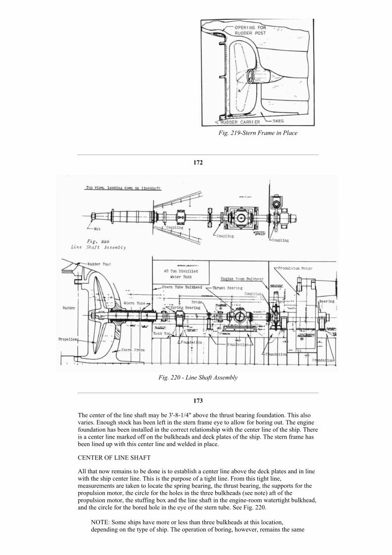
Fig. 219Stern Frame in Place
172
Fig. 220 Line Shaft Assembly
173
The center of the line shaft may be 3'81/4" above the thrust bearing foundation. This alsovaries. Enough stock has been left in the stern frame eye to allow for boring out. The enginefoundation has been installed in the correct relationship with the center line of the ship. Thereis a center line marked off on the bulkheads and deck plates of the ship. The stern frame hasbeen lined up with this center line and welded in place.
CENTER OF LINE SHAFT
All that now remains to be done is to establish a center line above the deck plates and in linewith the ship center line. This is the purpose of a tight line. From this tight line,measurements are taken to locate the spring bearing, the thrust bearing, the supports for thepropulsion motor, the circle for the holes in the three bulkheads (see note) aft of thepropulsion motor, the stuffing box and the line shaft in the engineroom watertight bulkhead,and the circle for the bored hole in the eye of the stern tube. See Fig. 220.
NOTE: Some ships have more or less than three bulkheads at this location,depending on the type of ship. The operation of boring, however, remains the same

Fig. 222Target Stand Assembly
in principle.
TIGHT LINE
The tight line used on this job is a piano wire, .018 of an inch in diameter. The same size ofwire and the same tension are employed each time a "tight line" is run. On oil tankers, thelength of the line is about 70 feet from one end support to the other. On other types of shipsthis distance will vary. Figure 221 shows these two supports: A "horse" on the outer face ofthe "eye" and a "line target" at the other end of the line, in the engine room. See "a" and "d".
Fig. 221Target Stands Set to Center Line of the Ship
SETTING THE TARGET STANDS OR SUPPORTS
The target is a centering device, or metal bar, which is bolted across the two columns of anangle iron support that may be bolted or tack welded to the deck plates or tank top. See Fig.222. In order to
174
set the target in the correct position, a chalk line is stretched from the engine room to theouter face of the eye at the stern, and by means of a plumb bob and line the chalk line islocated exactly above the center line of the ship. See Fig. 221.
NOTE: The center line of the ship was located by theshipfitters all along the tank top and on bulkheads withcenter punch marks as the ship was being built. The outsidemachinist follows all such center lines when laying out hiswork.
Figure 221 is a view looking down on the entire line shaftlocation as in the top view, Fig. 220. A "horse" 'a" is placedacross the sternframe eye. A target stand (See Fig. 222) isset in position as at "d". The chalk line "g" is adjusted untilits position is directly over the ship center line which wascenter punched on the deck by the shipfitters. A plumb boband line are used to determine the correct position of thechalk line.
The distance from "a" to "d" is about 70 feet, and a targetstand is set up, as at "e", every ten feet. The chalk line givesthe location for the center of the target stand and the heightof the target stand crossbar. When all the targets have beenplaced, the crossbars are adjusted so that they just abouttouch the chalk line on the under side. When doing this, make sure the chalk line is stretchedTIGHTLY.
NOTE: All target stands are not of exactly the same construction, but they all servethe same purpose. When the tight line has been run and the necessary pointslocated from the line, the target stands are stored away for the next job. Alwaysstore the target stands carefully, together with all bolts, nuts, and crossbars, so thatno time may be lost in looking for this equipment the next time it is to be used.
PLACING THE TIGHT LINE
The chalk line is now removed entirely. It has served its purpose. The support "a" is relocatedfor holding the tight line. See Fig. 223. Two brackets, "k", are tack welded in placetemporarily. These brackets support two stools "l". "a" is now supported by the stools. Thestools and the bar are bolted to the brackets and may be adjusted to bring the tight line into
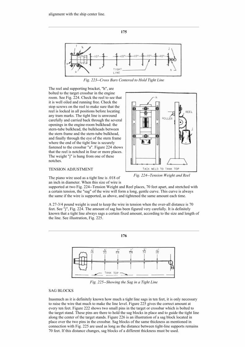
Fig. 224Tension Weight and Reel
alignment with the ship center line.
175
Fig. 223Cross Bars Centered to Hold Tight Line
The reel and supporting bracket, "h", arebolted to the target crossbar in the engineroom. See Fig. 224. Check the reel to see thatit is well oiled and running free. Check thestop screws on the reel to make sure that thereel is locked in all positions before locatingany tram marks. The tight line is unwoundcarefully and carried back through the severalopenings in the engineroom bulkhead: thesterntube bulkhead, the bulkheads betweenthe stern frame and the sterntube bulkhead,and finally through the eye of the stern framewhere the end of the tight line is securelyfastened to the crossbar "a". Figure 224 showsthat the reel is notched in four or more places.The weight "j" is hung from one of thesenotches.
TENSION ADJUSTMENT
The piano wire used as a tight line is .018 ofan inch in diameter. When this size of wire issupported at two Fig. 224Tension Weight and Reel places, 70 feet apart, and stretched witha certain tension, the "sag" of the wire will form a long, gentle curve. This curve is alwaysthe same if the wire is supported, as above, and tightened the same amount each time.
A 273/4 pound weight is used to keep the wire in tension when the overall distance is 70feet. See "j", Fig. 224. The amount of sag has been figured very carefully. It is definitelyknown that a tight line always sags a certain fixed amount, according to the size and length ofthe line. See illustration, Fig. 225.
176
Fig. 225Showing the Sag in a Tight Line
SAG BLOCKS
Inasmuch as it is definitely known how much a tight line sags in ten feet, it is only necessaryto raise the wire that much to make the line level. Figure 225 gives the correct amount atevery ten feet. Figure 222 shows two small pins in the target or crossbar which is bolted tothe target stand. These pins are there to hold the sag blocks in place and to guide the tight linealong the center of the target stands. Figure 226 is an illustration of a sag block located inplace over the two pins in the crossbar. Sag blocks of the same thickness as mentioned inconnection with Fig. 225 are used as long as the distance between tightline supports remains70 feet. If this distance changes, sag blocks of a different thickness must be used.
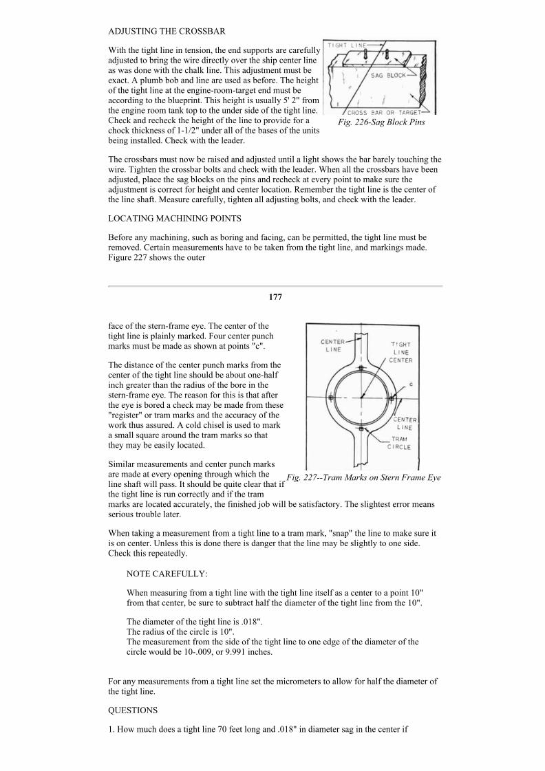
Fig. 226Sag Block Pins
Fig. 227Tram Marks on Stern Frame Eye
ADJUSTING THE CROSSBAR
With the tight line in tension, the end supports are carefullyadjusted to bring the wire directly over the ship center lineas was done with the chalk line. This adjustment must beexact. A plumb bob and line are used as before. The heightof the tight line at the engineroomtarget end must beaccording to the blueprint. This height is usually 5' 2" fromthe engine room tank top to the under side of the tight line.Check and recheck the height of the line to provide for achock thickness of 11/2" under all of the bases of the unitsbeing installed. Check with the leader.
The crossbars must now be raised and adjusted until a light shows the bar barely touching thewire. Tighten the crossbar bolts and check with the leader. When all the crossbars have beenadjusted, place the sag blocks on the pins and recheck at every point to make sure theadjustment is correct for height and center location. Remember the tight line is the center ofthe line shaft. Measure carefully, tighten all adjusting bolts, and check with the leader.
LOCATING MACHINING POINTS
Before any machining, such as boring and facing, can be permitted, the tight line must beremoved. Certain measurements have to be taken from the tight line, and markings made.Figure 227 shows the outer
177
face of the sternframe eye. The center of thetight line is plainly marked. Four center punchmarks must be made as shown at points "c".
The distance of the center punch marks from thecenter of the tight line should be about onehalfinch greater than the radius of the bore in thesternframe eye. The reason for this is that afterthe eye is bored a check may be made from these"register" or tram marks and the accuracy of thework thus assured. A cold chisel is used to marka small square around the tram marks so thatthey may be easily located.
Similar measurements and center punch marksare made at every opening through which theline shaft will pass. It should be quite clear that ifthe tight line is run correctly and if the trammarks are located accurately, the finished job will be satisfactory. The slightest error meansserious trouble later.
When taking a measurement from a tight line to a tram mark, "snap" the line to make sure itis on center. Unless this is done there is danger that the line may be slightly to one side.Check this repeatedly.
NOTE CAREFULLY:
When measuring from a tight line with the tight line itself as a center to a point 10"from that center, be sure to subtract half the diameter of the tight line from the 10".
The diameter of the tight line is .018".The radius of the circle is 10".The measurement from the side of the tight line to one edge of the diameter of thecircle would be 10.009, or 9.991 inches.
For any measurements from a tight line set the micrometers to allow for half the diameter ofthe tight line.
QUESTIONS
1. How much does a tight line 70 feet long and .018" in diameter sag in the center if

unsupported?
2. If the tight line is not located directly over the ship center line, how will this affect thealignment of the line shaft?
3. State the precaution which should be taken when locating tram marks with a center punch.
4. How does the mechanic make certain that the tight line is "on center" when takingmeasurements?
178
5. What device is used to hold the tight line at the proper tension?
6. What is the correct distance from one target support to the next?
7. Why is a chalk line run before setting the target supports?
8. Explain the reason for burning a hole larger than the stern tube in some bulkheads.
9. How does the diameter of the tight line affect a measurement taken from the center of thetight line to the circumference of any circle scribed about the tight line as the center?
* Removing A Tight Line
INFORMATION
The piano wire used for locating the shaft center line is comparatively expensive, and theslightest abuse can render it useless for further service. The time required to prepare anotherline would have to be added to its cost in case a second tight line had to be used. If a tightline is kinked, it is of no further use as a tight line.
MATERIALS
Tight line ready for removal
PROCEDURE
1. Unfasten the after end of the tight line from the adjustable bracket.
2. Have one helper hold loose end of line and carry it toward the reel which winds up the lineat the other end.
3. Have a second helper apply oil to the line with a rag.
4. Turn the reel crank, and wind the line on the reel neatly until all the wire is wound.
5. Secure the loose end by inserting it under two or three strands of line and then pulling it uptight.
6. Wrap an oiled rag around the line on the reel and place the reel of line in the reel box.
7. When you have finished with the line and the reel, see that they are returned to the toolroom.
QUESTIONS
1. Why must care be used in removing the tight line from the shaft center line location?
2. Three men are used in removing the line. What does each man do?
3. What precaution is taken before placing the reel of line in the box?
* Adapted from "Outside Machinist", Alabama State Department of Education.
179
Setting A Portable Boring Bar

Fig. 228Stern Frame
INFORMATION
The illustration at the right, Fig. 228, shows a heavy steel casting, the stern frame, which iswelded solid with the stern plates of a ship's hull. The hole in the hub is the sterntubehousing and is called the "eye" by shipyard mechanics.
The lower portion "a" is called the SKFG. The surface"b" is called the outer face of the eye and "c" is called theinner face of the eye. The sterntube housing must bebored out to a certain size to fit the stern tube. Seeappendix for definition of stern tube.
Figure 220 shows a longitudinal cross section of a ship'shull in the bottom view. Note carefully the locations ofthe bulkheads, bearings, stools, and couplings. The stoolswhich support the shaft bearings are welded to the tanktop before the tight line has been run. When theconstruction is complete, the center line of the line shaftmust occupy the same position as the tight line occupiedbefore it was removed.
While the tight line was in position, tram marks were accurately located on the outer face ofthe eye (Fig. 227) and around the rough hole in the sterntube bulkhead (Fib. 220). Trammarks were located on the engineroom watertight bulkhead and on the two bulkheadsimmediately forward of the stern frame.
The diameter of the portable boring bar is 5" to 14". A heavy bar is always used on largework. Always use as heavy a bar as possible to avoid spring. See Fig. 229. The diameter ofthe eye will easily accommodate the boring bar. Other holes in the bulkheads have beenburned out small enough for finishmachining and at the right location with the center line.
The eye in the stern frame is to be bored 30".
The hole in the first bulkhead forward of the eye is to be bored 31".
The hole in the second bulkhead forward of the eye is to be burned out 323/4" to allow thestern tube to pass freely, but it is not bored. If there are other bulkheads at this location, theblueprint will show which ones are to be bored and which are to be burned.
The hole in the engineroom bulkhead is bored 323/4" less about .003 of one inch. The .003of an inch is to allow for a press fit when pulling in the stern tube.
Study Fig. 229 carefully. The fittings on the main boring bar may all be removed, leaving abare bar. The entire assembly may be moved backward or forward and secured in any desiredlocation.
180

Fig. 229A Portable Boring Bar Assembly
Four stools, Fig. 229, swivel on the yokes and have several bolt holes to allow the yokes tobe secured to a support as conditions require.
The yoke on the end opposite to the handfeed wheel may be removed and the bar slippedinto the after end through the hole in the sternframe eye if the ship has twin propellers. Otherparts of the portable boring bar have to be removed while preparing to set the bar in a tightplace where one propeller is used. In this case it is lowered into the after peak and runthrough the eye from the inside.
The boring bar is slung in a chain fall and passed through the eye where a second chain fall isready to receive it. The bar is located by raising or lowering the chain fall; it is bracedsidewise as near to the center of the layout as possible by rough measuring. The yokes areadjusted to a convenient position, and supports to which the boringbar yokes may besecurely bolted are welded to the deck plates and bulkhead. See Fig. 230. These supports aresometimes called "spiders".
After the boring bar is secured to the spiders it may be adjusted to a location exactly centralwith the tram marks which were located from the tight line.
As the main bar of the boring bar assembly is straight and true, any measurements that maybe taken from the outside diameter of the bar will
181

Fig. 230Boring Bar Supports, Inside and Outside
be just as accurate as if taken from the actual center of the bar. Fig. 233 shows the boring barbody lined up in the center of the four tram marks which were put on the outside face of theeye while the tight line was still in place. Hermaphrodites may be used to check the distanceall around the boring bar until it is exactly in the center. The same procedure is followed atthe other end of the bar where it projects through the sterntube bulkhead. After the bar hasbeen securely bolted in position, the job is checked again to make sure of the alignment.
Figure 232 shows one of the bulkheads with a hole burned through. The four tram marks aremeasured from the tight line, and the boring bar is lined up with these tram marks.Measurements are taken from the tram marks as shown in Fig. 233, to the side of the boringbar as indicated by the reversed arrows. > DISTANCE X < The distance "x" betweenthe arrow points is the same all around the boring bar. This measuring must be done verycarefully.
Figure 231 shows a boring bar set vertically. The men are boring the top gudgeon on thestern post. Note the strong backs at the upper and lower sides of the gudgeon. Thestrongbacks are secured to the vertical channels welded to the rounding surface of thegudgeon.
182
Figure 230 shows a support welded to the "skeg" of the stern frame and bolted to thereductiongear housing. This is done to hold the boringbar assembly perfectly rigid while theboring is being done.
The job of setting up a portable boring barmay be summed up as follows:
PROCEDURE (Applicable in most cases)
1. Clear away all obstructions, tools, andloose materials which might interfere withthe handling of the boring bar.
2. Locate chain falls and planking atconvenient points for quick and safehandling of the boring bar.
3. Strip the boring bar of the yokes, toolholder, reductiongear drive, air motor, andhandfeed.
4. Lower the boring bar into the engineroom. Wrap with bagging to prevent injuryto the finished surface of the bar.

Fig. 231Portable Boring Bar Set Vertical
for Boring Rudder Gudgeon
Fig. 232
5. Secure the boring bar in the chain fallpreviously located in the after peak, andbalance the bar so that it may be swungforward. Planking is placed to help slidethe bar out through the eye in the sternframe. Protect the bar with bagging, ifnecessary.
6. Support the outer end of the boring barwith planking and chain fall.
7. Reassemble the yokes and otheraccessories, and get ready to raise the barinto boring position.
8. Estimate where additional spiders andsupports should be secured to supportboring bar.
9. Have flat or angle supports cut, andwelded into position.
183
10. Bolt boringbar spiders to supports, and line up the boring bar.
NOTE: Measure from outside diameter of boringbarmain body to the tram marks previously Placed on thesternframe eye and bulkheads. Use a steel scale andhermaphrodites. Keep the hermaphrodite scribing legto a sharp point. Re careful to hold the tool at rightangles to the center line of the boring bar. Themeasurements must be perfect if the stern tube is to bein correct alignment. Check with the leader.
11. install the tool holder, adjust the air motor,connect the air lines, and recheck all fastenings tomake sure the bar will remain in correct alignment.The boring bar should now be ready for boring the eyein the stern frame.
QUESTIONS
1. A heavy boring bar should always be used wherethere is sufficient room to set it up. Why is a heavy boring bar more desirable than a lightone?
2. What is the principal problem involved in setting a portable boring bar?
3. At what points are measurements taken to bring the boring bar central with the diameter tobe bored?
4. Explain the reason for removing the fittingsfrom the boring bar before setting through thesternframe eye.
5. Point out the principal precautions to be takenwhen getting ready to set the boring bar throughthe sternframe eye.

Fig. 233
6. What is the purpose of the swivels and yokes oneach end of a boring bar?
7. Explain the usual method of providing suitableplaces to which parts of the boring bar may be
184
bolted to hold the boring bar in position while the boring job is being done.
8. State at how many points supports for the boring bar are welded temporarily; explain thepurpose of each support.
9. What would be the probable result if a boring bar slipped a little during the boringoperation?
10. What is the correct procedure after the boring bar appears to be set central with the eyediameter?
Boring A Stern Frame
ACCURACY OF A BORING JOB
There must be no errors in the boring of a stern frame. The stern frame casting is "welded in"with the hull plates of the ship, after which operation all the pieces become one unit. To ruina stern frame means a loss of time and materials that is difficult to estimate. Boring a sternframe is a mansized job which the mechanic must approach with the fixed idea that everymove must be carefully and thoroughly planned. Mistakes are absolutely barred.
THE BORING JOB
Full instructions have been given for running a tight line. Full instructions have been givenfor setting a portable boring bar. The instructions given here are to be followed after theboring bar is in place, ready to bore the sternframe eye and the bulkheads, which wereshown in Fig. 220.
Fig. 234Portable Poring Par Set Horizontal for Boring a Stern Frame Eye
185
PROCEDURE
1. Adjust the tool holder and tool bit to the correct location. Turn the bar slowly to find wherethe high spots are on the inside of the eye. See Fig. 234.
2. Feed the tool into the full depth of the eye to make sure that there is plenty of clearanceand that there are no high spots to foul the tool and throw the "setup" out of line.
3. When everything seems to be clear, check with the leader.
4. Set the tool to take a 3/16" cut, and feed slowly to get the "feel" of the tool. A faster feedmay be used if it is evident that the tool will "hold up" and that there is no "spring" in the "setup." (A cutting speed of 30 to 60 feet per minute is safe in most cases. Check with the leaderon this point.)
5. Continue to take roughing cuts until the inside diameter of the eye "cleans up".
6. Check with the leader at this point. Check all spiders, yokes, and stools frequently to makesure there is nothing slipping.
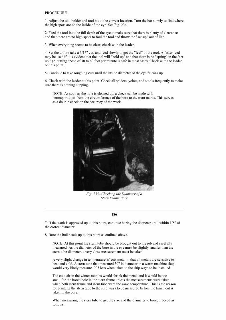
NOTE: As soon as the hole is cleaned up, a check can be made withhermaphrodites from the circumference of the bore to the tram marks. This servesas a double check on the accuracy of the work.
Fig. 235Checking the Diameter of a
Stern Frame Bore
186
7. If the work is approved up to this point, continue boring the diameter until within 1/8" ofthe correct diameter.
8. Bore the bulkheads up to this point as outlined above.
NOTE: At this point the stern tube should be brought out to the job and carefullymeasured. As the diameter of the bore in the eye must be slightly smaller than thestern tube diameter, a very close measurement must be taken.
A very slight change in temperature affects metal in that all metals are sensitive toheat and cold. A stern tube that measured 30" in diameter in a warm machine shopwould very likely measure .005 less when taken to the ship ways to be installed.
The cold air in the winter months would shrink the metal, and it would be toosmall for the bored hole in the stern frame unless the measurements were takenwhen both stern frame and stern tube were the same temperature. This is the reasonfor bringing the stern tube to the ship ways to be measured before the finish cut istaken in the bore.
When measuring the stern tube to get the size and the diameter to bore, proceed asfollows:

Fig. 236
(a) With a pair of outside calipers, carefully measure the diameter of the stern tube.
(b) Lay the outside calipers on a level surface and set inside micrometers to thepoints of the calipers.
NOTE:
Special inside micrometers are used for this job. Thereis an offset in the micrometer which will clear theboring bar. See Figs. 235 and 236.
MEASURING THE INSIDE DIAMETER OF THESTERNFRAME EYE.
187
(c) When the setting has been accurately determined, reduce the size .008 to allow for a pressfit. This must be done very carefully.
(d) Now proceed with the finish cut for about 1/8" and check with the micrometer. If the sizeis correct, proceed. If too large, back off and try again. DO NOT CUT IN LENGTHWISEFOR MORE THAN 1/8" BEFORE TRYING FOR SIZE. See Fig. 235.
Fig. 237Finish Cut in a Stern Frame
(e) When the bore checks correctly with the mikes, proceed with the finish cut. Watch thetool carefully as the boring proceeds. If the tool begins to burn, STOP. Check with the leaderif in doubt as to how to proceed. See Fig. 237.
If the finished hole is bored tapering, the stern tube will likely seize when being "pulled in";so every precaution must be used to have a straight hole.
NOTE: When finished with boring, do not move the boring bar until the diameter of the holehas been checked and approved by the leader or inspector.

188
QUESTIONS
1. When adjusting the tool holder to begin taking a cut, what precaution should be taken toprevent the tool's "fouling" the work?
2. How heavy should the tool be set in for the first cut in a sternframe eye?
3. At what speed is it considered safe to start a roughing cut?
4. What is understood by the phrase "clean up the inside diameter" of a boring job?
5. Explain the usual causes for the boring bar's getting out of line during a boring operation.
6. How is the rough bore checked for accuracy with the center location before proceedingwith the job?
7. How much stock is left for a finish cut in a roughbored "eye"?
8. State the usual allowance for a press fit between the "eye" and the sterntube diameter.
9. Explain how the measurement is taken for the finished diameter of the bore in the "eye".
"Pulling in" A Stern Tube
PURPOSE OF A STERN TUBE
The stern tube is the shell for the lignum vitae, tailshaft bearing. The stern tube varies from8 to 20 feet in length. The outside diameter is stepped, that is, the end that fits in the sternframe eye is smaller than the end that fits in the sterntube bulkhead.
CORRECT FIT FOR A STERN TUBE
When the sternframe eye and the sterntube bulkhead are bored to the finished size, the sterntube should "pull in" under pressure, because the stern tube is turned .008 of an inch largerthan the sternframe eye at the stern end (see point "a" Fig. 238), and .003 larger than thesterntube bulkhead at the bulkhead end (See point "b", Fig. 239). Figure 239 illustrates atube partially pulled into place.
USING THE CHAIN FALLS
When the bored holes in the sternframe eye, sternframe bulkhead, and the interveningbulkheads have been brought to size to allow for a pressed fit as outlined in the lastparagraph, the' stern tube is lowered into the engine room. Chain falls are placed in positionto take the stern tube off of the crane. Sometimes as many as 8 or 10 chain falls are used tocarry the stern tube as it is worked back to its place from one chain fall to another. The sterntube must be protected with bagging to prevent scoring the finished surface while the tube isbeing handled by the chain falls.
189

Fig. 240
Fig. 238Stern Tube in Place
PREPARING TO "PULL IN" THE STERN TUBE
Figure 239 shows the stern tube partly drawn in through the sternframe eye and the sterntube bulkhead at "a" and "b". A heavy bolt is shown at "c". The bolt extends from the outsideof the bulkhead end of the stern tube, through a strong back "d", and all the way through thestern tube and the strong back "e". A hydraulic ram "f" is secured to the outside of the strongback "e". The ram draws the stern tube into place.
Two cradles, Fig. 240, are used under the pull bolt to keep it exactly central in the sterntubebore. The cradles and made an easy fit for the sterntube bore and the pull bolt. One cradle isplaced at the sternframe end, and the other is placed at the sterntube, bulkhead end. See "x"and "y", Fig. 239.
"PULLING IN" THE STERN TUBE
The hydraulic ram works against the washer and nut at "g" and has an effective draw of about10 inches. When the ram has reached the 10" limit, another washer (10") "h" is placedbetween the strongback and the first washer under "g" and another 10" section of tube isdrawn in. This is repeated until the stern tube is completely drawn into place, making ametaltometal joint at the sterntube shoulder and forward end of eye. See Fig. 238.
Fig. 239"Pulling In" a Stern Tube
190
A pressure of not less than 3500 pounds registered on the gauge isstandard for a correct fit. This pressure may run as high as 6000pounds, but it must not be less than 3500 pounds. A pressure gaugeis connected to a hydraulic pump which acts on the ram. The gaugeshould be watched constantly for variations which will indicate toomuch or too little pressure.
The lock nut, Fig. 241, has in the circumference, several machinednotches into which the spanner wrench fits when the nut is beinginstalled or removed. When the lock nut has finally been "snugged home", a hole is drilled inthe face of the sternframe eye and tapped out for a lock stud. The location of this hole bringsthe lock stud at the bottom of one of the notches. After the lock stud has been secured inplace, tack weld it fast. See "a" Fig. 241.
When the stern tube comes to the job, it is packed withsawdust to keep the lignum vitae bearing blocks fromdrying out and cracking. Never remove the sawdust untilready to null the stern tube into place. While the operationof pulling in a stern tube is proceeding, the job isinspected and criticized by the American Bureau ofInsurance, or the Lloyd Insurance Company, and the agentof the shipowner. This is done to make certain that the jobwill conform to all underwriter requirements.

Fig. 241Lock Nut
The operation of pulling in a stern tube may be summedup as follows:
TOOLS ANDEQUIPMENT
1. Hydraulic pump2. Hydraulic ram3. Strongback assemblies4. Pull bolt5. Saddles for pull bolt6. Washers for pull bolt7. Sterntube nut wrench8. Drill for lock stud9. Air drill10. 30pound sledge11. Chain falls12. Melting ladle13. Pouring ladle14. Heating torch
MATERIAL
Planking for skids andplatformWhite lead and oilLock studTight metal
191
Fig. 242Inspecting the Progress of the Stern Tube Through the Eye
Fig. 243

192
PROCEDURE
1. Lower the stern tube into the engine room.
2. Receive the stern tube in one or more chain falls, and swing to the next chain fall, passingthe tube aft.
3. Enter the tube in the bulkhead hole, and pass it through to the sternframe eye.
4. Apply white lead and oil to the tube, bulkhead, and eye surfaces.
5. Install the pull bolt, and adjust strongbacks and hydraulic ram.
6. Pump pressure until the pull bolt takes hold.
7. Now examine all equipment and fastenings to make certain the tube is entering "fair".
8. Pull the tube in as outlined in the text of this instruction sheet.
9. When the tube is in place, check with the inspector for his approval.
10. If approved, remove strongbacks, hydraulic ram, and pullbolt; clear the platform forinstalling the lock nut.
11. Drill through the sterntube flange for studs, and tap holes to suit.
12. Install studs with grommets and nuts on the after side of sterntube bulkhead. See Part II,Making a Watertight Joint, Fig. 145 for application of stud and grommet.
13. Place a metal band around the flange of the stern tube in readiness for pouring tightmetal.
14. Build up a clay mud seal all around the ring to prevent the tight metal's escaping when itis poured into the joint.
15. Build up (on top of the metal band) a clay mud cup into which the tight metal may bepoured.
NOTE: While the metal band is being placed and the mud seal is being installed,the tight metal should be made ready. The tight metal is melted in a ladle over aheating torch. The metal is considered to be hot enough to pour if a pine stick takesfire when inserted in the melting metal. This test indicates approximately atemperature of 535° to 550° F.
16. Pour the tight metal into the cup previously prepared. Pour fairly fast to insure a goodjoint and avoid air pockets.
NOTE: In cold weather the bulkhead and the sterntube flange should be preheatedto prevent chilling the metal as it is poured.
17. Remove the band and calk the tight metal with a rough calking tool. This procedure willtighten up the joint and make certain there are no gas or air pockets.
193
NOTE: In the event that a gas pocket or an air pocket is discovered, the metal mayhave to be melted out and repoured. This is almost sure to be necessary if thepocket is found on the bottom side of the joint.

18. Install washers and nuts on the studs, and draw up tight. See Fig. 243.
19. Fill up the after peak with water from a shoreline hose to make the necessary test forleakage around the joints between the sterntube flange and bulkhead and the stern tube andsternframe eye.
QUESTIONS
1. Why is a forced fit necessary between a sterntube diameter and the sternframe eye?
2. How much difference in diameter should there be between the bore in the sternframe eyeand the after end of the stern tube?
3. Explain how a stern tube is carried back into position after 'it is lowered into the hull.
4. What protection should be given a stern tube during the operation mentioned in step 3?
5. What is the purpose of the two cradles which are placed under the pull bolt in the sterntube?
6. State the reason for pulling in the stern tube with a pressure of 3500 lbs. registering on thegauge.
7. When is the sawdust removed from the inside of the stern tube? Why is it not removedsooner?
8. When is the sterntube job inspected and by whom?
9. What is meant by the word "fair"?
10. Why is a small space left between the sterntube bulkhead and the sterntube forwardflange? ("c" Fig. 238)
11. Explain in as few words as possible how and why tight metal is poured at the forward endof the stern tube.
12. How are the sterntube joints tested for leakage after the installation is complete?
Installing A Propulsion Motor
PROPULSION MOTOR DRIVE
The propulsion motor is keyed to one end of the line shaft, and the propeller is keyed to theother. When the propulsion motor turns, the propeller turns at the same speed and so movesthe ship through the water. The propulsion motor (See Fig. 244) is electrically operated, verymuch like any other electric motor except that it is installed on the forward end of the lineshaft; the line shaft thus becomes the axle upon which the rotor turns. The foundation isinstalled according to the location given on the blueprint. Figure 244 shows the motor
194
housing and the line shaft housing. The motor is inside the large housing. Note handleswhich are used to grasp the housing sections when opening or closing the housing assembly.
Unless the installation of the propulsion motor iscorrect in the smallest detail it will not be passedby the inspector. The propulsion motor islowered into the ship by ship riggers, set hack asfar off on the foundation as possible to giveclearance for installing the rotor, and after therotor is installed the entire stator unit is shifted tothe correct position on the foundation.
PRECAUTION
Every precaution should be taken when installingthe stator to make sure that there is no damagecaused to either the rotor or the stator. It isadvisable to place shims around the inside of thestator to serve as guides when sliding the rotorinto place.

Fig. 244Propulsion Motor and Line Shaft
INSTALLING THE MOTOR
At the time the final installation is made, the lineshaft has already been installed. See Fig. 220.The propulsion motor must be set directly withthe line shaft for the line shaft cannot be moved.This calls for extremely careful measuring. Therotor shaft is set in line with the line shaft. As thepropulsion motor weighs sixteen tons or more,the entire job must be done carefully.
When the motor is set in position and approvedby the inspector or the leader, the job of fittingchocks is begun. When the chocks are fitted, thecorners are drilled and reamed for fitted bolts;the bolts are installed and drawn down tightly;and then the rotor shaft is revolved and"indicated" to make sure it is in perfectalignment with the line shaft.
A piece of insulation approximately .125" thickis placed between the top side of the chock andthe pedestals of the propulsion motor on theforward bearing. After the chocks are fitted andare found to be satisfactory, they are removedand an amount equal to the thickness of
195
the insulation is machined off of the top of each chock. This job must be done very carefullyor the alignment of the other chocks will be thrown off.
The fitted bolts through the forward bearing are insulated at the point where the bolts passthrough the pedestal and the upper side of the chock. These points are insulated to prevent aground on the forward bearing. See Fig. 245 and 246.
If an arcing condition should be set up, the shaft and the babbit bearing in the propulsionmotor would be scored and both would have to be replaced. Such an arcing condition mustbe made impossible by proper insulation.
TOOLS
1. Drills of the correct size2. Corner drilling machine3. Reamers for couplings (taper and straight)4. Reamers for holddown bolts5. Open wrench set6. Scrapers7. 6" scale8. Thickness gauge (.002".060")9. 24" inside calipers Or Special telescopic gauge
MATERIALS
Shim stock
10. Taper gauge (0".390")11. Center punch12. Machinist's hammer13. 10lb. maul14. 201b. maul15. Necessary taps16. Jacking screws17. Diesel side jacks
GENERAL PROCEDURE
1. Find the correct location of the rotor unit onthe foundation from the blueprint. Level theunit on chocks or wedges, or both, preparatoryto bolting down.
2. Align the couplings on the rotor shaft and theline shaft.

Fig. 245Line Shaft Bearing and Pedestal
3. Check with the leader.
4. Fit chocks as previously instructed (See PartI) under the bearing pedestal of the rotor.
5. When the chocks are correctly fitted, checkwith the leader.
6. If the work up to this point is approved,proceed to drill and ream the corner holes forfitted bolts.
196
Fig. 246Typical Insulated Stud Installation
7. Install fitted bolts and draw the nuts down tightly. Be sure to install the insulated boltscorrectly.
8. Check the alignment of the rotor shaft with the line shaft to make sure there has been noerror.
9. Using jacks or wedges, line the stator up with the rotor and check the spacing between therotor and the stator with a 12" tapered wedge gauge. See Fig. 247.
NOTE: The propulsion motor is set "up and down" to align with the line shaft .005of an inch above the center. This is to allow for wear as the motor "settles" in thebearings. The foreandaft location is found on the blueprint.
10. When the rotor and stator appear to be in perfect alignment all around, check with theleader. If the alignment is correct, fit the chocks under the stator base.
197

Fig. 247The Stator is Jacked Up True With the Rotor
11. Drill, ream, and install fitted bolts on the four corners. Pull the nuts up tightly. Use everyprecaution to insure the nuts being pulled up to the limit.
Fig. 248Typical TurboGenerator Unit
198
12. Recheck the spacing between the rotor and the stator.
13. Call the leader, and have the job inspected up to this point. Figure 248 shows a turbogenerator and exciter set. Several of these units are installed in the engine room or adjacent tothe engine room, and they generate power which is used to drive the propulsion motor andnumerous other electric motors throughout the ship. The ship lighting system also drawscurrent from the turbogenerators.
QUESTIONS
1. When a propulsion motor is being installed, why is the rotor aligned before the stator?
2. Explain the procedure of aligning the stator with the rotor.
3. How often is the spacing checked between the rotor and the stator?
4. Why is the stator aligned with the rotor in such a way that the center line of the rotor is.005 of an inch above the center of the stator?
5. Describe a diesel side jack.
Installing Fan And Motor For Air Cooler
FAN REDUCES TEMPERATURE
The temperature in the vicinity of the propulsion motor normally varies from 150 to 180
degrees Fahrenheit. As the propulsion motor is installed in the engine room, it is subject tohigh temperatures caused by heat radiated from the steam lines and absorbed by thesurrounding atmosphere. in winter these temperatures are reduced somewhat by coolerweather; but in summer, and in southern climates especially, the temperature around thepropulsion motor must be reduced or the motor will run so hot that it may burn the bearings.
An air cooler is installed in a convenient place; a fan and motor are connected to the aircooler by a "circulating duct"; and the air around the motor is drawn through the air coolercontinuously, bringing the temperature down to about 115° Fahrenheit. See Fig. 249.
CORRECT INSTALLATION
The importance of correct installation of the aircooler fan cannot be stressed too much.When the ship is in service, there is an extremely heavy load on the propulsion motor. If forany reason the fan and motor should stop working, the temperature would likely go so highthat the motor windings would be in danger of burning out. If this should happen while theship is at sea, the results may be easily imagined.
FAN AND MOTOR UNIT
The fanandmotor units are usually mounted on a base as one unit. Sometimes the fanandmotor units come separate. In either case the work involved in making the installation ismuch the same.
199
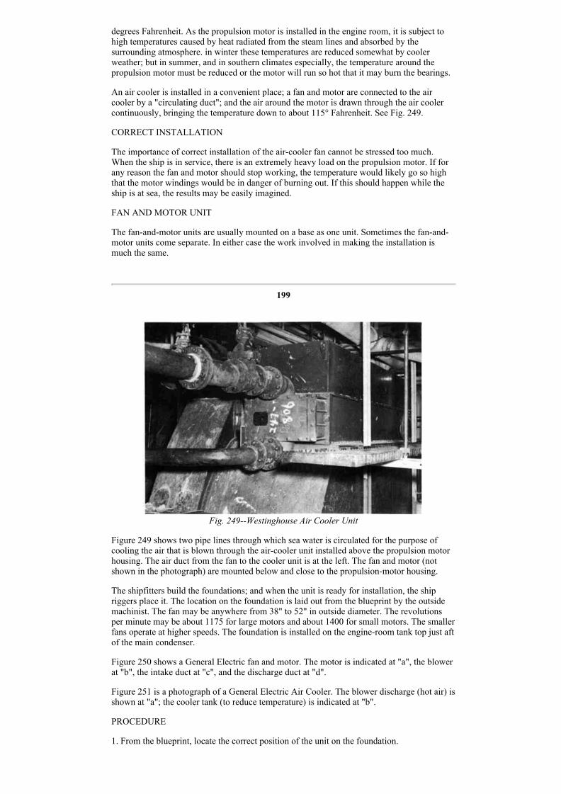
Fig. 249Westinghouse Air Cooler Unit
Figure 249 shows two pipe lines through which sea water is circulated for the purpose ofcooling the air that is blown through the aircooler unit installed above the propulsion motorhousing. The air duct from the fan to the cooler unit is at the left. The fan and motor (notshown in the photograph) are mounted below and close to the propulsionmotor housing.
The shipfitters build the foundations; and when the unit is ready for installation, the shipriggers place it. The location on the foundation is laid out from the blueprint by the outsidemachinist. The fan may be anywhere from 38" to 52" in outside diameter. The revolutionsper minute may be about 1175 for large motors and about 1400 for small motors. The smallerfans operate at higher speeds. The foundation is installed on the engineroom tank top just aftof the main condenser.
Figure 250 shows a General Electric fan and motor. The motor is indicated at "a", the blowerat "b", the intake duct at "c", and the discharge duct at "d".
Figure 251 is a photograph of a General Electric Air Cooler. The blower discharge (hot air) isshown at "a"; the cooler tank (to reduce temperature) is indicated at "b".
PROCEDURE
1. From the blueprint, locate the correct position of the unit on the foundation.

200
Fig. 250General Electric Motor and Fan
2. Level the unit on wedges preparatory to bolting down.
3. Drill the corner holes for fitting bolts through the foundation.
NOTE: Usually the unit is bolted down on metal chocks, but sometimes a woodcushion of suitable thickness is used to reduce vibration. (In this case metal chocksare not used.)
4. Fit corner chocks; drill, ream, and install fitted bolts; and draw down.
5. Fit the remainder of the chocks.
6. Have an inspector check the job for accuracy.
201

Fig. 251General Electric Discharge Duct and Cooler Tank
Installing A Steam Boiler
DESCRIPTION OF A STEAM BOILER
Tankers and certain types of cargo ships are usually equipped with the boiler which isdescribed here. The boiler is built in the shipyard by the boilermakers. When completelyfinished, the boiler is set on the ship by the riggers and bolted down by the outsidemachinists.
The boiler is known as a Babcock and Wilcox, oilfired, tubularheader type. This unitweighs approximately fortysix tons when completed. Fig. 252.
202
Fig. 252Babcock and Wilcox Oil Fired boiler
THE FOUNDATION
A foundation is constructed in the boiler room. The boiler room in a tanker is located in theafter end. The boiler room in a cargo ship is located amidships. The shipfitters build thefoundation, which is of heavy construction. It is finished off with two steel channels that

support the boiler, back and front. The foundation seat is a channel about 14" wide and 18"high. See Fig. 253.
The channel is welded securely to the foundation plate, and the boiler is bolted down to thechannels. The channels are called "stools".
Six 11/4" bolts are placed through each of the four bottom corners of the boiler frame andthe foundation stools.
LAYING OUT THE BOLT HOLES IN THE STOOLS
The locations of the bolt holes in the stools are taken from the blueprint. Before laying outthe holes in the stools, however, boilermakers check the base ofthe boiler to make sure theholes in the base match with the hole locations on the blueprint. If there is any discrepancy,the layout is corrected to agree with the boiler base. Figure 254 is a ton view of a foundationstool on the port side of the ship. A similar foundation is on the starboard side right next tothe port foundation. Two boilers are installed with about 3 feet between the adjacent walls.
When the machinist lays out the boiler locations, he takes all measurements from the shipcenter line, the boiler center line, and the foundation center line.
203
Fig. 253Boiler Foundation Setting
SETTING THE BOILER
The boiler is picked up by the shipriggers and set on the foundation under the supervision ofthe outside boilermaker leader. This is not done until after the holes are drilled in thefoundation stools A layer of seal tight cement about 1/8" thick is spread on the surface of thefoundation stools with a trowel. When the boiler is set on the stools, the cement forms acushion for the boiler and seals any uneven places on the surface. The cement hardensquickly, and thus a solid, durable joint is formed between the foundation and the boiler base.
Figure 252 shows various valves, gauges, and controls which are installed by mechanicsespecially trained for this purpose.
PRECAUTIONS
Certain precautions must be observed when installing any of the gauges, valves, and otherparts mentioned above.
(a) Examine the fittings closely to find if righthand or lefthand threads are cut on theconnections.

204
(b) Be very careful in handling brass fittings not to damage the fine threads.
(c) Use a wrench of the correct size on all fittings, and see that the wrench fits closely. (Somewrenches may be "sprung" although they are stamped the correct size.)
(c) Follow the directions given by the manufacturer or the shipbuilding company'sblueprints.
Fig. 254Plan View of Steam Boiler Foundation
Many of these accessories appear to be simple in form and do not seem to require any specialknowledge to install. This is far from true. Each particular piece of equipment requirescorrect handling and careful treatment.
As an example of the importance of working carefully and correctly, consider the work ofinstalling a Bailey feedwater regulator. The purpose of the regulator is to control the amountof water fed to the boiler so that it will not run dry and cause burning of the tubes. Theregulator also prevents an excess of feed water which causes "wet" steam and damagesturbine fins or cracks a cylinder head.
205
* Bailey Feed Water Regulator InstructionsPrincipal of Operation See Fig. 255
The Bailey ThermoHydraulic Feed Water Regulator depends for its operation upon the factthat the volume of a given weight of low pressure steam is far greater than the volume of thewater from which that steam was made. The water which operates the regulator is sealed in aclosed system formed by the annular space between the inner and outer generator tubes, theconnecting copper tubing, and the metal bellows of the regulating valve.
When the regulator is placed in operation, heat from steam in the upper portion of the innergenerator tube causes the surrounding water to flash into steam. This forces water out of theannular space in the generator through the connecting tubing into the metal bellows whichexpands and opens the regulating valve.
If the boiler water level tends to rise, cold water from water storage leg J rises up into theinner generator tube. This cold water plus radiation secured from the fin surface of the outertube causes steam in the annular space to condense, thereby reducing the pressure in theclosed system and allowing the spring to close the regulating valve.
In normal operation, the regulation valve adjusts its position to correspond with the rate ofsteaming as reflected by slight changes in water level and a continuous feed is delivered tothe boiler.
How to Fill Generator When Valve is Above Generator
1. Jack valve open by means of handjack K.
2. Disconnect tubing, R from metal bellows D.

3. Remove Guard H from bellows D, and place bellows in large bucket full of water.
4. Compress bellows many times with open end up until all the air is removed and bellows isfilled solid with water.
5. Insert end of tubing ft in bucket of water along with bellows.
6. Remove generator plug G, and draw on opening until water syphons from bucket outthrough generator.
7. Allow water to run until all air is carried out of line, and then insert plug G.
8. With bellows under water, place Guard H over bellows and connect end of tubing R tobellows. Make sure that end of tubing R and bellows are completely submerged during thisoperation so that no air gets into the system.
9. Replace guard H, and bellows on valve.
10. Release handjack K so that valve spring is free to close valve.
11. Remove generator plug G, and permit excess water to run out.
12. Replace plug G and make sure that connections at both ends of copper tubing, as well asplug G, are made up tight.
* Through the courtesy of Bailey Meter Company, Cleveland, Ohio.
206
Fig. 255Principle of Operation of Bailey Feed Water Regulator
13. Open valves F and F, and blow down generator by opening valve P.
14. After generator has had time to cool off, regulator is ready for service.
How to Fill Generator When Valve is Below Generator
15. if practical, remove bellows and tubing to an elevation higher than the generator, andfollow same procedure, as when valve is above the generator. If not, jack valve open, removetubing R, and proceed as follows:
16. Remove bellows from valve, and insert in bucket full of water.
17. Compress bellows many times with open end up until all the air is removed and bellows

is filled with water.
18. Place end of copper tubing Q in another bucket of water, and draw on end of coppertubing R until syphon is started.
19. Place end of tubing R in bucket with bellows, and allow water to flow until all air hasbeen washed out of tubing.
207
20. Stop flow of water by holding finger over end of tubing Q, and at the same time placeguard H over bellows and connect end of tubing R to bellows. Make sure that end of tubingand bellows are completely submerged during this operation so that no air gets into system.
21. Replace Guard H and bellows on valve.
22. Connect end of tubing Q to generator.
23. Remove plug G from generator, and fill generator with water until it overflows at plug.
24. Release handjack K, and allow excess water to run out.
25. Replace plug G and make sure that connections at both ends of tubing, as well as plug G,are made up tight.
Fig. 256
26. Open valves F and F, and blow down generator by opening valve P.
27. After generator has had time to cool off, regulator is ready for service.
28. Generator should be blown down periodically; once in 24 hours is good practice. Alsogenerator should be blown down whenever regulator is placed in service after the boiler hasbeen out of service.
29.Spring tension on regulating valve has been adjusted at factory so that valve begins toopen when a pressure of 35 pounds per square inch is applied to the metal bellows. Thisadjustment should not be changed.
30. Do riot make up packing nut tight enough to jam valve stem. Make up only fingertight.
31. Make sure there is no excessive friction or rubbing of regulating valve parts. A mixture ofgraphite and oil applied to guides and valve stem is helpful.
32. The water level carried by regulator is determined by location of generator. As will benoted from a curve, the relation between water level and valve travel varies with changes in

Fig. 257Section through BaileyFeed Water Regulator Valve
the
208
boiler pressure. It may be necessary, therefore, to lowerthe level of generator with respect to normal boilerwater level for higher pressure, and to raise it for lowerpresses. Under average conditions, generator filling plugis located 1 to 11/2 inches above normal water level.When deciding on a generator location, it is well toestimate the gauge glass level which will result whenthe valve is in a closed position. This may be done byfollowing boiler pressure line to the lefthand edge ofcurve, and by reading the distance in inches betweenthis intersection and the proposed line of normal gaugeglass level which will be somewhere below the level ofthe generator filling plug.
33. If regulating valve closes completely at too low awater level, this indicates that too little water is in thesystem and that the system should be refilled.
34. If regulating valve does not close completely untilwater level gets too high, there is too much water insystem and a small amount should be allowed to drainout.
35. Water level carried by regulator under normal loadconditions is determined largely by excess of feedwaterpressure. Increasing feedwater pressure raises waterlevel, and decreasing feedwater pressure lowers waterlevel. Best results will be obtained if the excess pressure shown on the valve data sheet ismaintained.
36. If regulator carries a gradually lower and lower water level, this indicates a leak insystem. If leak is not apparent, put a teaspoonful of borax in water and refill. After regulatorhas run for several hours, a grayish mark will appear at point of leakage.
37. Never paint generator or radiator J.
38. Regulator should operate indefinitely without adding water to generator.
39. When it is necessary to add water, close valves F and E and open valve P. After generatorhas cooled, remove plug G and
209

Fig. 258 Section through Bailey Feed Water Valve Body showing construction of Tight
Seating Inner Valve.
add water to overflowing. Make sure the valve is in closed position when this is done.
40. If there is air in system, completely refill in accordance with previous instructions.(Paragraphs 1 to 14 or Paragraphs 15 to 27.)
Installing Winches
DESCRIPTION OF WINCHES
A winch is a mechanically operated device which, by means of a special arrangement ofgearing and drums, pulls a rope, a cable, or a chain at various speeds. (Fig. 259.) These ropes,cables, or chains may be attached to the ship's cargo booms, docking hawsers, or anchors.
The winch mechanism is usually steamoperated.
The operator usually controls the winch by means of throttle and brake mechanisms. Thecontrols are shown clearly in subsequent illustrations.
The drums, or capstans, which are fastened to the driveshaft extensions are correctly slopedto fit the ropes, or cables, that may be wrapped around the drums. See Fig. 259. The smalldrum "t", Fig. 259, is grooved to receive a wire cable. This drum and the drum on the portside are sometimes used for emergency steering. When the power is applied to the winch, therope or cable winds up, and a pull will be exerted upon whatever is fastened to the other endof the rope. The object on the other end of the rope will have a tendency to move toward thewinch.
210
Fig. 259Starboard Side of After Deck Winch
CLASSIFICATION OF WINCHES
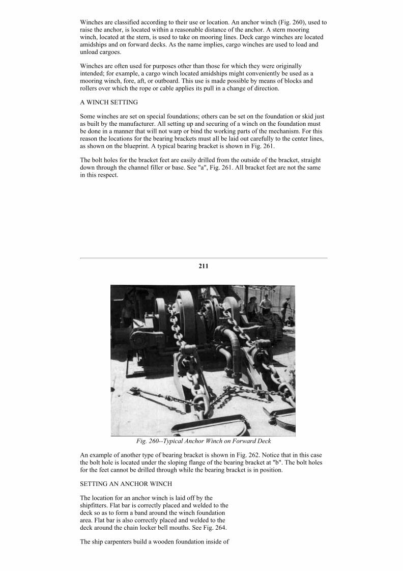
Winches are classified according to their use or location. An anchor winch (Fig. 260), used toraise the anchor, is located within a reasonable distance of the anchor. A stern mooringwinch, located at the stern, is used to take on mooring lines. Deck cargo winches are locatedamidships and on forward decks. As the name implies, cargo winches are used to load andunload cargoes.
Winches are often used for purposes other than those for which they were originallyintended; for example, a cargo winch located amidships might conveniently be used as amooring winch, fore, aft, or outboard. This use is made possible by means of blocks androllers over which the rope or cable applies its pull in a change of direction.
A WINCH SETTING
Some winches are set on special foundations; others can be set on the foundation or skid justas built by the manufacturer. All setting up and securing of a winch on the foundation mustbe done in a manner that will not warp or bind the working parts of the mechanism. For thisreason the locations for the bearing brackets must all be laid out carefully to the center lines,as shown on the blueprint. A typical bearing bracket is shown in Fig. 261.
The bolt holes for the bracket feet are easily drilled from the outside of the bracket, straightdown through the channel filler or base. See "a", Fig. 261. All bracket feet are not the samein this respect.
211
Fig. 260Typical Anchor Winch on Forward Deck
An example of another type of bearing bracket is shown in Fig. 262. Notice that in this casethe bolt hole is located under the sloping flange of the bearing bracket at "b". The bolt holesfor the feet cannot be drilled through while the bearing bracket is in position.
SETTING AN ANCHOR WINCH
The location for an anchor winch is laid off by theshipfitters. Flat bar is correctly placed and welded to thedeck so as to form a band around the winch foundationarea. Flat bar is also correctly placed and welded to thedeck around the chain locker bell mouths. See Fig. 264.
The ship carpenters build a wooden foundation inside of

Fig. 261Bearing Bracket
Fig. 262Bearing Bracketwith Inside Bolt Holes
Fig. 263Bolt Holes Laid Out
the band area upon which the winch is to be bolted down.
The setting of an afterdeck winch differs in some respectsfrom the setting of an anchor winch and will be explainedfully under the heading, "Setting a Deck Winch".
212
TOOLS AND EQUIPMENT
1. Number 4 corner airdrilling machine
2. Drillsa. 1 fulllengthb. 1 halflengthc. 1 12" extension (the sizes of the drills depend on theholes in the base of the winch)
3. Shipfitter's taper reamer (bolthole size)
4. Chalk line
5. Center punch
6. Full set of wrenches
7. 1 3/4lb. hammer
8. 6' tape
9. 50' tape
10. Pocket knife
MATERIALS
2 round steel bars 18" long (These bars mustfit the hole in the winch base easily, butsnugly.
Red leadTarred feltTack GrommetsStuds WashersNuts
Fig. 264Layout for Chainlocker Bell Mouths

213
The job of setting an anchor winch may be outlined as follows:
PROCEDURE
1. Find the center between the two chainlocker bellmouths in the deck.
2. Snap a chalk line "aa" fore and aft on the wood foundation, parallel with the center line ofthe ship, and passing through the center between the chainlocker bellmouths in the deck.See Fig. 264. Distance "WW" is the same length.
3. Snap a second center line "bb" at right angles to center line through port to starboardcenters of the chain locker openings.
4. Locate a foreandaft center line on the base of the winch. Measure from port to starboardon the base of the winch, find the center of the base, and center punch mark the, edge of thebase. Do this fore and aft.
NOTE: There are openings in the winch base, port and starboard, through whichthe anchor chains fall so that they may be stowed in the chain lockers below decks.These openings must line up with the chainlocker openings in the deck. Theoutboard edges of the winch base must he marked with a center punch so that thecenters of the openings in the base can be set exactly over the line which was snapped on the foundation in step 3.
5. Measure the distance from the forward edge of the winch base to the center of the chainopening in the base.
6. Lay off this distance on the outboard edges of the winch base and mark with center punch.
NOTE: These center line marks on the winch base must correspond with the chalkline which was snapped on the wood foundation.
7. Have the winch set by the riggers.
NOTE: The ship riggers set the winch on this foundation under the supervision ofthe outsidemachinist leader.
8. After the winch has been set by the riggers, go below into the chain locker and inspect thealignment of the winchchain holes with the chainlocker openings. The centers whenchecked are equal fore and aft and port and starboard. Adjust the winch if necessary.
9. When the winch has been adjusted to the proper location on the foundation, have thecarpenters inspect the wood foundation.
NOTE: At this point the ship carpenter checks the fit between the base of thewinch and the wood foundation for high spots.
10. Drill all bolt holes, using the holes in the base of the winch as a guide. The holes aredrilled through the wood foundation and through the steel deck. Check carefully whendrilling to make sure that there are no electric cables immediately beneath the holes. Consultthe leader if there are obstructions.
214
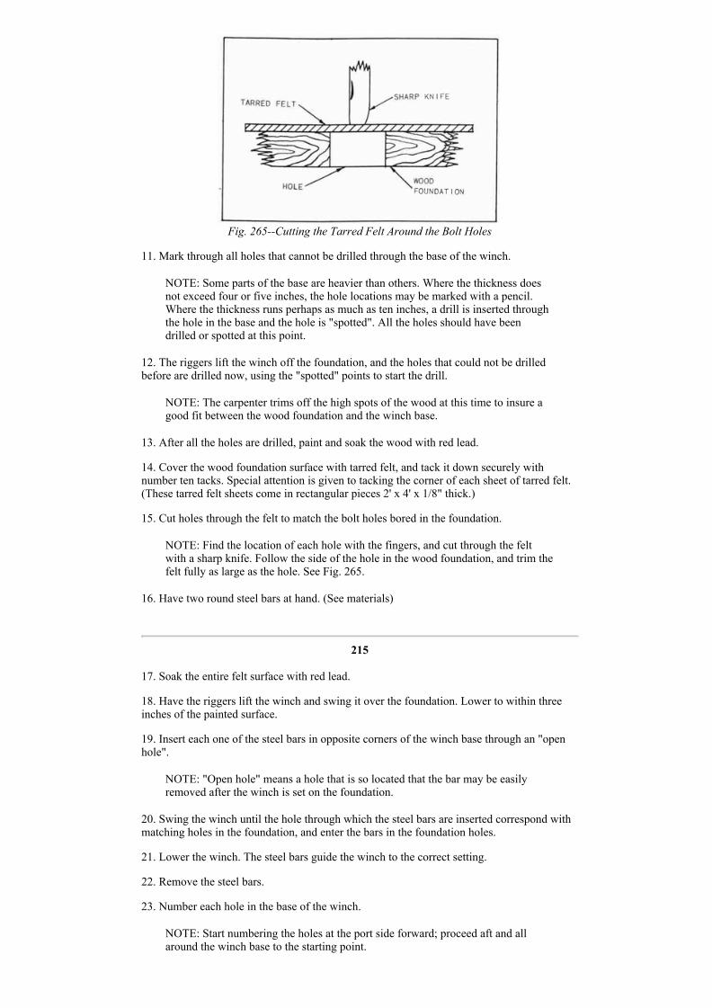
Fig. 265Cutting the Tarred Felt Around the Bolt Holes
11. Mark through all holes that cannot be drilled through the base of the winch.
NOTE: Some parts of the base are heavier than others. Where the thickness doesnot exceed four or five inches, the hole locations may be marked with a pencil.Where the thickness runs perhaps as much as ten inches, a drill is inserted throughthe hole in the base and the hole is "spotted". All the holes should have beendrilled or spotted at this point.
12. The riggers lift the winch off the foundation, and the holes that could not be drilledbefore are drilled now, using the "spotted" points to start the drill.
NOTE: The carpenter trims off the high spots of the wood at this time to insure agood fit between the wood foundation and the winch base.
13. After all the holes are drilled, paint and soak the wood with red lead.
14. Cover the wood foundation surface with tarred felt, and tack it down securely withnumber ten tacks. Special attention is given to tacking the corner of each sheet of tarred felt.(These tarred felt sheets come in rectangular pieces 2' x 4' x 1/8" thick.)
15. Cut holes through the felt to match the bolt holes bored in the foundation.
NOTE: Find the location of each hole with the fingers, and cut through the feltwith a sharp knife. Follow the side of the hole in the wood foundation, and trim thefelt fully as large as the hole. See Fig. 265.
16. Have two round steel bars at hand. (See materials)
215
17. Soak the entire felt surface with red lead.
18. Have the riggers lift the winch and swing it over the foundation. Lower to within threeinches of the painted surface.
19. Insert each one of the steel bars in opposite corners of the winch base through an "openhole".
NOTE: "Open hole" means a hole that is so located that the bar may be easilyremoved after the winch is set on the foundation.
20. Swing the winch until the hole through which the steel bars are inserted correspond withmatching holes in the foundation, and enter the bars in the foundation holes.
21. Lower the winch. The steel bars guide the winch to the correct setting.
22. Remove the steel bars.
23. Number each hole in the base of the winch.
NOTE: Start numbering the holes at the port side forward; proceed aft and allaround the winch base to the starting point.

24. Measure the length of the bolts required for each numbered hole, and list the sizes on aconvenient scratch pad.
NOTE: Measure each hole from the top of the base to the underside of the deck.To this dimension add sufficient length to allow for a nut and a halfnut on the topof the base; allow for a grommet, washer, and nut below deck. (For example: a bolt11/2" in diameter requires 21/2" on top and 13/4" below. If the "metal to metal"length measures 8", then the total length of the bolt will be 8" 21/2" 13/4" 121/4".) The leader, however, usually checks for the bolt length. There must be 1/2"more thread on the respective bolt ends than is required for the thickness of thenuts.
25. Order studs from the machine shop. These studs are made of special steel.
26. Go below deck, and with the corner airdrilling machine ream all the bolt holes in orderto take care of misalignment and clear the holes of slivers.
27. Install all the studs beginning at the inboard holes. Tighten each stud reasonably tight.Check with the leader.
28. Have the entire job inspected.
SETTING AN AFTERDECK WINCH
An afterdeck winch is located on the poop deck aft of the galley. The outside machinist boltsthe foundation angles to the base of the deck winch according to the blueprint. Shipfitters layout the location for the winch and then set it. The shipfitters tack weld to the deck and thenbrace the angles which the outside machinist bolted to the winch base. The winch is thenlifted from the angles, and the foundation is completed by the shipfitters; brackets and strutsare welded in place to stiffen and make the foundation solid.
216
When the shipfitters have completed the foundation, the outside machinist levels off thesurface of the winch base. The painters are then notified to apply a coat of suitable protectivepaint. The foundation is now ready for the setting of the winch.
CAPSTAN SHAFTS
This type of winch is equipped with capstan shafts that extend some distance beyond thewinch. Port and starboard couplings connect the capstan shaft to the main driving shaft.These shafts may extend for as much as 4 feet and are supported port and starboard by one ormore bearing pedestals. The bearing pedestals (called bearing brackets) are set to carry thecapstan shaft in correct alignment with the main driving shaft. Suitable foundations areplaced under the feet of the bearing pedestal, and they are welded to the deck. Bearingbrackets are bolted to these foundations with fitted chocks between foundations and pedestalfeet. See Figs. 252, 266 and 271.
Fig. 266After Deck Winch Showing Controls
Figure 266 shows the starboard side of an afterdeck winch. The foot pedal "a" controls thebrake. The hand lever "b" controls the motive power. The foundations are formed in theblacksmith shop. A flat plate approximately 1/2" thick, and of the correct size, is heated andbent to the channel shape shown in Fig. 263. The flat top of the foundation is then planed offlevel and true in the machine shop. It is on this machined surface that the locations for the

bracket feet are laid out. In Fig. 263 are shown center lines which indicate the center of thefoundation lengthwise and crosswise, and the centers of the bolt holes.
217
TOOLS AND EQUIPMENT
1. Portable grinder2. 8" outside calipers3. 8" inside calipers4. Full set of wrenches5. Drills (diameter of the drill depends on the diameter of the boltholes in the winch base and brackets)6. Shipfitter's taper reamer (bolthole size)7. Center punch8. 13/4 lb. hammer9. 6' tape10. 50' tape11. 14" secondcut flat file12. No. 4 corner airdrilling machine13. 14" square bastard file14. Thickness gauge15. Cclamps16. Scriber17. Dividers18. Oilstone19. Spoonbearing scraper20. Hermaphrodites
MATERIAL
Garlock packingChalkBoltsNutsWashersPiece of 11/16" roundstock 6" long
The job of setting an afterdeck winch may be outlined as follows:
PROCEDURE
1. Procure from the shipfitter the side angles upon which the winch is to be set.
2. Block up the winch about one foot high all around.
3. Chalk one leg of each side angle for the entire length and clamp the chalked side to thewinch base in a foreandaft position, one angle to port and one angle to starboard; place thelegs of the angles inboard with the edges of the angles extending beyond the winch baseabout 1/2". See Fig. 267. The ends of the angles project beyond the winch base about 11/2"fore and aft. Divide the distance so that the angles project the same amount fore and aft, evenif the distance is more or less than 11/2".
Fig. 267Winch Base Blocked Up for Placing Side Angles

Fig. 268Marking Bolt
Hole Centers
218
4. Scribe through the holes in the winch base, and mark the locations of these holes on theangles.
NOTE: Scribing the hole locations must be done very carefully because there is noroom to use a reamer to line up the holes after they are drilled.
5. Mark the angles on one end, and place a similar mark on the winch base above the angles(make the mark with the center punch). This will enable the mechanic to replace the angles inthe correct location.
6. Remove the angles, and make four similar punch marks, spaced equally around thecircumference of each bolt hold circle. See Fig. 268.
7. With the dividers, find the center of the scribed circle. SeeFig. 82 "Removing Broken Studs and Bolts", Part I, for methodof procedure.
8. Center punch the center at the intersection of the divider lines.
9. Drill a 3/8" pilot hole through all centers. See Part I,"Reaming Through Holes", Fig. 64, for pilothole procedure.
10. Select a drill of the same diameter as the hole in the winchbase, and drill through the pilot hole.
11. Measure for the bolt lengths, and allow for a nut, plus 1/2"beyond the actual thickness of winch base and angle.
12. Check for the proper angle location (See step 5), and bolt the angles to the winch base.
NOTE: The shipfitters have laid out the location of the winch on the poop deck.
13. Have the ship riggers lift and place the winch on the previously laid out location on thedeck.
14. Have the shipfitter level the winch and weld the angle edge to the deck. The outsidemachinist leader checks the job for correct installation at this point.
15. Remove the bolts, and lift the winch off the foundation so that the foundation may befinished by the shipfitters.
NOTE: The shipfitter welds gussets, angles, and cross plates in position to stiffenthe foundation.
16. Grind off the top of the foundation all welding burrs which might interfere with the levelfit between the Winch base and the foundation top.
17. Notify the painter, and have the foundation painted with antirust solution.
18. Set the winch back on the foundation. Bolt securely, and lock all bolts with halfinchnuts.
219
19. Remove the fitted bolts from the main drive shaft of the winch, and clean the bearingsurface. Check for and remove any rough spots with the oilstone.
NOTE: To avoid losing the fitted bolts, wire them together and wire the bundle tothe winch.
20. Check the number which is stamped on the main shaft coupling, and find the matchingnumber on the capstan shaft coupling.

Fig. 269Blocking of the Capstan
Fig. 270Spigot Coupling Support
21. Have the riggers block up the capstan. Whenthis operation is complete, line up the capstan asclose as possible with the main drive shaft. Thecapstan should be blocked with two wooden wedgesto prevent it from shifting.
NOTE: The inboard end of the capstan shaft is heldtemporarily by the spigot coupling. One bolt isplaced loosely through the coupling to preventslipping. See Fig. 270.
22. Layout center lines on the top of the channelfoundation as shown in Fig. 263.
23. Locate the center of the bearing bracket on theedge of the base, fore and aft, port and starboard.Center punch these centers. See "x" and "y". Fill.271.
24. Place the bearingbracket center on the channelfoundation center. Center the bracket on the channelfoundation fore and aft, port and starboard, to matchthe centerpunch mark and the center lines.
NOTE: Chalk the machined surface of the channelfoundation so that the "lay out" lines will stand outclearly.
25. Scribe through the holes in the bearing bracket.Mark the foundations and the base of the bearingbracket so that the locations will not be lost.
26. Center punch the circumferences of the holes asin step 6, and locate center as in step 7.
220
Fig. 271Marking the Rearing Bracket Centers
27. Center punch mark at the intersections of the divider lines.
28. Drill 3/8" pilot holes through the centers.
29. Select a drill of the same size as the diameter of the hole in the bearingbracket base, anddrill pilot holes through.
30. Clean up the machined bearing surface on the capstan shafts, and stone any rough spots.
31. Remove the cap from the bearing bracket, and clean any rough surfaces carefully.
32. Apply grease to the shaftbearing surfaces.
33. Slide the bottom half of the bearing bracket on the shaft, and block up temporarily.

Fig. 272Placing Garlock
Packing
Fig. 273Coupling Face Allowance
34. Place a piece of garlock packing at the top side of the shaft on the bearing surface. Thispacking should be the width of the bearing and about 1/3 of the shaft circumference inlength.
35. Replace the base cap on the bearing bracket over thegarlock packing.
36. Bump the bearing bracket out to the capstan hub toclear the shaft of the hub about .030 of an inch.
37. Tighten the bearing cap on the garlock packing so asto draw the bottom half of the bearing bracket tight to theshaft. See Fig. 272.
38. Check the coupling between the main drive shaft andthe capstan shaft. The bottom of the coupling should belined up at the bottom .003 "open", and about .015between the faces of the couplings. See Fig. 273.
221
39. Check the marks on the foundation with the marks on the bearing bracket, and slide thecorrect foundation under the bracket. If the foundation is too high to set, have it roughburned off until it will slide under easily.
40. Bolt the foundation to the bottom of the bracket with temporary bolts. Draw the bolts uptight.
41. Chalk the foundation about. 1" above the deck on both sides for the entire length.
42. Recheck the coupling for clearance as shownin Fig. 273.
43. Measure with the square, and level thefoundation with the deck fore and aft.
44. Set the "morphs" to 1", and scribe on thechalked surfaces parallel lines on both sides of thefoundation.
45. Remove the bolts, and remove the foundation.
46. Center punch mark the foundation along thescribed lines on both sides 11/2" apart.
47. Have the foundation burned off to these centerpunched lines.
48. Knock off the slag and rough sides of the burned edges with a hammer.
49. Slide the foundation back to the former position under the bracket, but on the deck,leaving a 1" space between the top of the foundation and the bottom of the bracket.
50. Insert two pieces of round stock, easy bolthole size, through the bolt holes in theopposite corners of the bracket base and the holes in the foundation. This operation will serveto line up the foundation holes with the bracket holes.
51. With fox wedges, raise one side of the foundation until it is 11/16" higher than the otherside, thus forming a wedgeshaped space between the foundation and the bracket base.
52. Recheck the coupling for clearance as in Fig. 273.
53. Have the welders tack all four corners of the foundation to the deck.
54. Recheck the wedgeshaped space as in step 51 to make sure that the foundation is 1/16"higher on one side than it is on the other side.
55. If correct, weld the foundation to the deck inside and outside for the entire length.
50. Place heel wedges between the foundation and the bearing bracket, two forward and twoaft. The bracket is now supported on the heel wedges.

57. Remove blocking from under the capstan.
222
58. Use a piece of scrap metal to make a strongback to lay across the bracket edge. Drillholes for the bolts. Place two bolts long enough to pass through the strongback and reach tothe deck. Weld the bottom end of the bolts to the deck. Place nuts and draw down tight. SeeFig. 271.
59. Weld a piece of flat bar to the deck aft of bearing bracket about 2". A hole is drilledthrough the plate bar for a bolt. The bolt is used as a backing screw to prevent the bracket'sdrifting aft. See Fig. 274.
Fig. 274Using a Flatbar Stop and an Adjusting Screw
60. Check all adjustments for alignment; readjust if necessary.
61. Take chock sizes and order chocks.
62. Fit chocks.
63. Scribe holes in chocks, and have them drilled.
64. Place chocks, install the bolts, and draw down tightly. Lock with the halfnuts.
65. Remove the heel wedges.
NOTE: Repeat on the opposite side of the winch all of the steps hereinenumerated. Both sides are worked together.
66. Recheck coupling. See Fig. 273. If the alignment is the same as it was before, have theinspector approve the job. If the coupling is out of alignment, the chocks will have to berefitted.
67. Drill and install 1/2" dowels on opposite corners of the bearing brackets. See Fig. 275.
NOTE: The dowels are turned .502 of an inch in diameter and threaded for 3/4 ofan inch on one end. The thread is for the purpose of removing the dowel ifnecessary. The dowel must be long enough below the thread to pass through thebracket and the foundation. The threaded end of the dowel must be undercut toform a shoulder, and the end must be slightly rounded as in Fig. 275 at "b".
223
Run a nut on the threaded end of the dowel flush with the shoulder before starting to drivethe dowel into place. This nut will prevent mushrooming the end of the dowel under thehammer when the dowel is driven into place.
Drill the dowel holes with a 31/64" drill. After drilling, ream through with a 1/2" handreamer. The dowel should drive in with medium force.
68. Remove the bearingbracket cap, and take out thegarlock packing.
69. Clean out the bearing cap. Clean up the shaft.
70. Grease the shaft, replace the bearing cap, andtighten down.

Fig. 275Drive Fit Dowel
71. Check with the feelers and allow .012 of an inchclearance between shaft and bearing. If more than.012, remove a shim. If less than .012, add a shim.
72. Clean up feed bolts and coupling.
73. Drive fitted bolts through coupling, and draw allnuts down snugly.
74. Drill and dowel the base of the deck winch on thefoundation.
75. Grease the entire mechanism, and prepare it foroperation.
Installing A Steering Gear and Telemotor ForPilot House Indication
GENERAL DESCRIPTION OF MAIN STEERING GEAR
The main steering gear controls the position of the ship's rudder. A ship's rudder weighs asmuch as 24 tons and steering the ship by hand as is done in a small pleasure boat is notpossible.
A mechanically operated device which is known as a steering gear is installed in the afterpeak on a deck called the steeringgear flat. Certain motors, pumps, and other mechanismsare installed on the steeringgear flat which control the operations of the steering gear.Control wheels are installed in the wheelhouse and on top of the wheelhouse. Thewheelhouse is located on the navigating bridge deck.
Other control wheels are located on the steeringgear flat forward of the main steering gear.The control wheels actuate the steering mechanisms by means of hydraulic power which istransmitted from control wheel to steering gear through a pipe line connecting thewheelhouse with the steeringgear room. Hence, the entire installation is known as the ship'ssteering gear. The port side of the forward end of the steeringgear engine is shown in Fig.276.
224
Fig. 276Port Side of Steering Gear in Steering Gear Room
ALIGNING STEERING GEAR MECHANISMS
The entire steeringgear mechanism is lined up with the center line of the rudder stock.Hence, the rudder must be placed and the rudder stock installed before the work of installingthe steering gear may begin.
Figure 277 shows the rudder (a), the rudder stock (b), the rudder trunk (c), the carrier bearing(d), the bearing disk (e), the carrier and brake drum (f), the tiller (g), and the keeper ring (h),installed in position. All of these parts must line up with the rudder stock center line fore and

aft, port and starboard.
The procedure for the installation of these parts up to the point where the installation of thesteering gear commences is as follows:
1. Weld the rudder trunk (c) in position as shown.
2. The rudder is placed and the gudgeon pins installed as shown in Fig. 277 at "z".
3. The rudder is raised and a steel block 2" thick is inserted between the upper gudgeon eyeand the rudder to hold the rudder in this raised Position. See Fig. 277 at "x".
4. Install the rudder stock (b).
5. Install the carrier bearing (d).
225
NOTE: The carrier bearing is bolted to the rudder trunk.
6. Install the bearing disk (e).
7. Install the carrier and brake drum (f), and have the brake hand in position on the brakedrum to be connected to the brake lever later.
NOTE: The two halves of the carrier and brake drum are not tightened snugly untilthe rudder is lowered into working position.
8. Install the tiller (g).
9. Install the keeper ring (h).
10. Lift the rudder enough to remove the 2" block which was placed to raise the rudder inStep 3.
11. Lower the rudder into position so that the rudder carrier takes the entire weight of therudder assembly.
12. Tighten the bolts through the two halves of the rudder carrier and brakedrum casting,securing the carrier to the rudder stock.
13. Swing the rudder to port and starboard and check it against the rudder stops for thecorrect angle with the ship center line. If the angle is not correct, add to or take away fromthe rudder stops.
14. Bring the rudder to amidship position and secure with chain falls from the tiller to theshell of the ship. 15. Install the packing and the split packing glands shown at "j", Fig. 277.
INSTALLING MAIN STEERINGGEAR RAMS AND CYLINDERS
The foundations for the main steeringgear ram and cylinders are "A" "A" "A", Fig. 279.Figure 281 shows this unit extending athwartships. Note the two heavy bolts, "B" "B" whichact as a support for the followup gear bearing and pinion. These bolts are shown at "B", Fig.280 and at "B", Fig. 282. The bolts tie the port and starboard rams and cylinders together andensure their correct alignment.
The foundation tops, Fig. 279, "A", "A", "A", are roughleveled off with a portable grinderand finishground with a portable surface grinder. The surfaces of the foundation tops areground level and smooth for a distance of approximately 10" from the edge, fore and aft.This 10" level plane surface slopes from nothing to the outside about 1/64 of an inch, but notmore than 1/32 of an inch. A long straight edge is used to check the amount of slope. See Fig.287.
This procedure is carried out on all the foundation tops shown in Fig. 279, "B""B", "C""C","D", "E", "F", and "G".
The shipriggers pick up the main unit and lower it to the foundation "A" "A". The unit is thenleveled and brought to the correct position fore and aft, port and starboard. The job is nowready to have the chocks fitted and the bolts installed through the base. This main ram andcylinder unit must be in place before proceeding to install any of the other parts of thesteering gear.
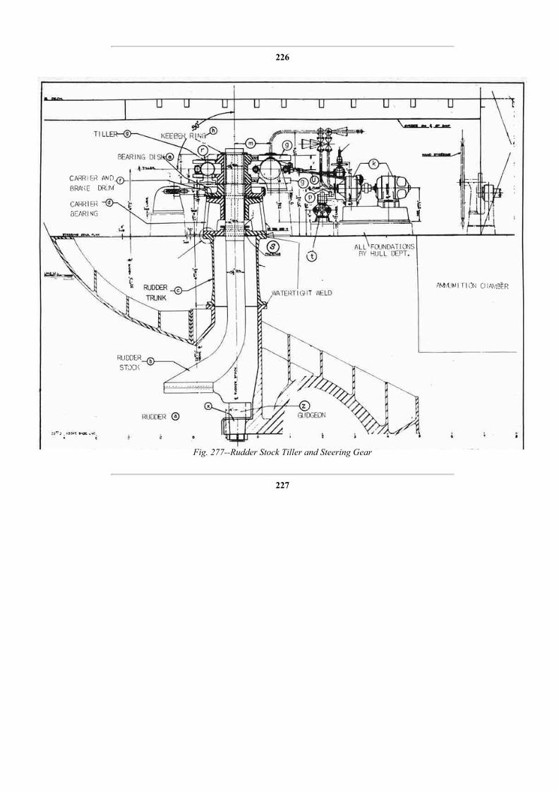
226
Fig. 277Rudder Stock Tiller and Steering Gear
227

Fig. 278Cast Steel Rudder Trunk
228

Fig. 279Foundation Plan for Main SteeringGear Rams and Cylinders
229

Fig. 280Plan View of Steering Gear Installed on Steering Gear Flat
230
Fig. 281Main steeringGear Ram and Telemotor
16. inspect the position of the ram in the cylinders, and make any necessary adjustment tobring the pivot hole in the ram to the foreandaft center line of the ship.
17. Weld angle clips at convenient places to clear the corner chock positions at points shownat "a", Fig. 286. Complete the welding of angle clips to both main ram foundations.
NOTE: Angle clips are welded to the foundations in this manner so that heavysetscrews may be used through the clips to adjust the unit fore and aft, port andstarboard. The clips must be drilled and tapped for 3/4" bolts.
18. Drill holes for 3/4" jacking screws through the base of the unit as shown in Fig. 289 at"b" according to the dimensions given. See Fig. 277.

19. By means of the jacking screws through the unit base and the set screws through theangle clips, adjust the position of the main ram and cylinder until the athwartship center lineof the ram is at right angles to the vertical center line of the rudder stock and at right anglesto the foreandaft ship center line. See Fig. 277, 90° angles. (See Fig. 280).
NOTE: Figure 290 at "g""g" tiller jaws, shows a dimension "n". The distancefrom the top side of these tiller jaws to the center is the same. The center of thesteeringgear main cylinder must be at a point 1/4" below this
231
Fig. 282Front View of SteeringGear Looking Aft
center, which is between the top and bottom of the tiller jaws. See Fig. 277 at "g", Fig. 282,and Fig. 290 at "g".
20. Begin at the inboard, forward corners of the port foundation ("d", Fig. 286, Chock #1),and measure for chock sizes. Fill out a chock sheet for each chock.
NOTE: The position of each chock is numbered 1, 2, 3, 4, etc. Number each chockand its position with white paint. Mark the position of the chock on the base of theunit. Chock #2 is the next one to port. Follow in this direction (to port), and gocompletely around the foundation' to the inboard and aft corner. Go across to theStarboard and aft corner of the starboard foundation, continue from the inboard,after corner, and go completely around the foundation to the inboard, forwardcorners. See Fig. 286 for location of the chocks. There is a chock for every bolthole. See Fig. 276.
21. Send the chock sheets to the shop, and order the chocks machined according todimensions given on the sheets.
22. When the chocks are returned to the job, begin fitting the correct chocks as follows:
232

Fig. 283HeleShaw HandSteering Pump
233

Fig. 284Plan and Elevation of Telemotor Copper Piping
See explanation of numbers on page 245
234

Fig. 285Differential FollowUp Control.
235
Fit #1 chock 1st. (See Step #5)Fit #7 chock 2nd.Fit #8 chock 3rd.Fit #14 chock 4th.
(These chocks are on the port foundation.)
Fit #15 chock 5th.Fit #21 chock 6th.Fit #22 chock 7th.Fit #28 chock 8th.
(These chocks are on the starboard foundation.)
Fig. 286Port Foundation for Main Steering Ram
NOTE: Corner chocks are fitted first as outlined above because they will thenserve as a reference when fitting intermediate chocks. Example: when numbers 2,3, 4, 5, and 6, are being fitted the base of the unit could easily he raised and the job

Fig. 289Adjusting Screw Through Base
thrown out of line. As each chock is fitted, the corner chocks are checked with athickness gauge to make sure they are tight. The corner chocks should be checkedfrequently while the other intermediate chocks are being fitted.
23. Fit the intermediate chocks.
Fig. 287Checking Foundation Top with a Straightedge
236
Fig. 288Jacking Screws Tack Welded to Foundation Top
24. Scribe through the holes in the unit base on all eight corners, and mark the position of theholes which are to be drilled in the corner chocks.
25. Remove the corner' chocks, and center punchmark the circumference of each hole. Find thecenter of the holes with the dividers; center punchmark the centers; and send the chocks to themachine shop for drilling. Give the machine shopthe size of holes required.
26. When the chocks are returned, place them inposition and drill the holes through the foundation,using the hole in the unit base for a guide. See Fig.61.
BILL OF MATERIALS
A partial bill of materials which goes into the fabrication and assembly of a steering engine isgiven below. To identify the type and grade of material; compare the keynumber on theFigures 284, 297, 299, with the bill of materials.
For example: The number 12 in the circle in Fig. 297 is found in the column at the left in thebill of materials. Reading across from
Fig. 290Tiller Jaw Center 1/4" Above Ram Center
237

Fig. 291Pump and Motor Unit Foundation
the number, we find 3/4" standard 900 Ell, brass. In the small circles on Fig. 297 will befound the number 12. Each number 12 on the Figure means that the materials given opposite12 in the bill of material are to be used at that point.
Follow this same procedure with all the other numbers in the circles in these three figures.
In Fig. 277 the letter "s" is found in one of the circles. This material is 1" square packing.
NOTE: When because of limited working spaceit is impossible to drill a fullsized hole in thefoundation, the workman places a bushing inthe hole in the unit base and drills a pilot holewith a small drill. It is then possible to getunder the foundation with a large drill and adrilling machine and drill the hole to the fullsize from below.
27. When the corner holes are drilled, reamthem to size as shown on the blueprint.
28. Order 28 fitted bolts to fit the reamed holes.Give the machine shop the sizes of the bolts.
29. When the fitted bolts are ready, install them on all eight corners first and draw up snugly.
NOTE: The corner bolts are fitted first to prevent any possible misalignment of theunit.
30. Scribe through the unit base holes, and mark the hole locations on all the intermediatechocks. Locate the centers as in step 10.
31. Send the chocks to the machine shop to be drilled. Give the shop the size of the hole.
32. When the chocks are returned, install them in the correct location and ream as in step 12.
Fig. 292Telemotor Foundation
238
33. Install the remainder of the fitted bolts, and pull them up snugly.
34. Install port and starboard motor and pump units "k" (See Fig. 280, Fig. 281, Fig 282)according to the blueprint.
NOTE: Followup gear "L" must be installed and lined up at the same time themotor and pump units are installed. This is done to insure the correct alignment onall three units. These units are lined up with jacking screws for height and positionas was done when lining up the main cylinder and ram units. See Fig. 289.
35. Fit, the chocks and install the fitted bolts as was done with the main cylinder and ramunits. See Fig. 291 for location of bolt holes.
INSTALLING THE TELEMOTOR
Figure 284 at "p", shows two small lugs connected by a pin. The pin must he a slip fitthrough both lugs, and it must slide easily. The forward lug is connected with the followupgear and the after lug is part of the telemeter leg which is connected o the telemotor.
The foundation for the telemotor is shown at "e", Fig. 279. The telemotor is shown at "t",Fig. 277, and at "t", Fig. 280. The telemotor must be installed on the foundation and alignedwith the followup gear. Figure 285 shows the followup gear and the pin at "c". See Fig. 292

Fig. 294Emergency HandSteeringCylinder and Ram Foundation
for location of bolt holes in the foundation.
Fig. 293Telemotor Rack Foundation
PROCEED
36. Install the telemeter rack and align with the followup gear. See fig 279 at "d" forlocation.
37. Chock the telemotor and bolt down. See Fig. 293 for location of bolt holes.
35. Install the telemeter and align it with the telemeter rack.
39. Chock the telemeter and bolt down.
239
NOTE: Check frequently to insure the sliding fit of pin "p". Figures 277 and 284.
40. Install the followup gear universal control rod "U", shown in Figs. 277 and 280.
NOTE: Figure 292 shows two chocks at "hh" which do not have bolts. Thesechocks act as a support under the telemotor, midway between the end chocks, andare tack welded as shown at "ww". Care must be taken to have the welders tackthese chocks to the foundation.
EMERGENCY, HANDSTEERING MECHANISM
Figures 277, 280, and 284 show the emergency, handsteering cylinder and ram. Figure 279"R" shows the foundation for these parts.
41. Install the emergency, handsteering cylinder and ram units, and align the center line ofthe unit in the same manner as was done in step 4 in aligning the main ram and cylinder. SeeFig. 294 for location of bolt holes.
42. Chock the unit, and bolt down.
BRAKELEVER UNIT
In step 7 the brake band was installed to be connectedto the brake lever later on. The brakelever unit isnow to be installed. Figure 279 at "f" shows thefoundation for the brakelever unit. Figure 280 at "v"shows the brakeband connection with the brakelever. Figure 280 also shows the brakeleveradjusting screw at "w". The adjustingscrew unitmust be installed at the same time as the brake leverin order to secure a correct alignment. Figure 303shows

Fig. 296
Screw Foundation
Fig. 297HandSteering Pump Foundation
Fig. 295Brake Foundation
240
the brake, the brake lever, and the brakeadjusting screw assembled on the foundations, inFigs. 295 and 296.
INSTALLING THE BRAKE LEVER AND SCREW
The brake lever and the brakelever adjustingscrew units are nowinstalled and aligned with the brake band which was previously placedin position on the brake drum. The brake edges must line up with theflanges on the brake drum and not "cross" the plane of the brakedrumflanges. When the alignment is correct, the bottom edge of the brakeshould clear the bottom flange of the Crake drum about 1/16 of an inch.The base of each of these units is adjusted to the correct height withjacking screws. When the alignment is correct, the chocks are fitted,drilled, reamed, and bolted down according to standard procedure.
HAND PUMP AND FILLING TANK
Figure 298 shows a hand pump and a filling tank both of which are parts of the telemotorsystem. The liquid for the hydraulic mechanism is poured into the tank, and the pump is usedto circulate the liquid and distribute it throughout the telemotor lines. The foundation for thepump is two 3" angles welded to the deck after the pump has been bolted to the angles. Anangle foundation for the tank is welded to the deck, and the tank is strapped down securely.
HELESHAW HANDSTEERING PUMP
Figure 280 at "y" shows a hand steering pumpwhich is used for emergency steering when theelectric power fails on the main unit. Turningthe hand wheel operates the pump which in turnoperates the emergency rams "RR", Fig. 280.
The unit is bolted to the foundation, withoutchocks. A shim may be used to compensateunevenness in the foundation.
The holes in the foundation are located from thebase of the unit which is already drilled whenreceived. See Fig. 297 for the locations of theholes in the foundation. The unit is lined up withthe bulkhead.
STEERINGGEAR CONTROL
Figure 299 shows the steeringgear control inthe wheelhouse and on the wheelhouse top. Figure 300 is a crosssection view of the base ofthe steeringgear column in the wheelhouse. Figure 301 is a crosssection view of the base ofthe steeringgear column on the wheelhouse top. Bosses are welded to the deck as at "a".Studs are screwed into the
241

Fig. 298Plan and Elevation of Telemotor System in Steering Gear Room
See explanation of numbers on Page 245
242
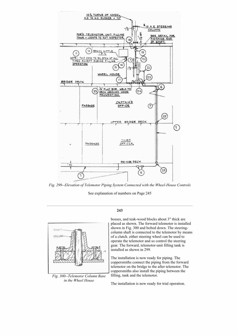
Fig. 300Telemotor Column Base
in the Wheel House
Fig. 299Elevation of Telemotor Piping System Connected with the WheelHouse Controls
See explanation of numbers on Page 245
243
bosses, and teakwood blocks about 3" thick areplaced as shown. The forward telemotor is installedshown in Fig. 300 and bolted down. The steeringcolumn shaft is connected to the telemotor by meansof a clutch. either steering wheel can be used tooperate the telemotor and so control the steeringgear. The forward, telemotorunit filling tank isinstalled as shown in 299.
The installation is now ready for piping. Thecoppersmiths connect the piping from the forwardtelemotor on the bridge to the after telemotor. Thecoppersmiths also install the piping between thefilling, tank and the telemotor.
The installation is now ready for trial operation.

Figure 302 is part of a steamoperated steering gearshowing telemotortothrottlevalve control andtrickwheel control.
Fig. 301Telemotor Column Baseon the Wheel House Top
Fig. 302Steam Operated SteeringGear
244

Fig. 303Brake Lever Unit
See explanation of numbers on Page 245
245
EXPLANATION OF NUMBERS ON FIGURE 284
No.1 1" Fig. (600#) F.S. Male End Slip on Type 24158552 17 Fig. (600#) F.S. Female End Slip on Type 21458553 1" Tubing Seamless Steel Ex. R.Y. IPS4 1" Welding Tee Seamless Steel Ex. H.Y. Pipe Thkss.5 1" By Pass Valve F.S. 2119585
EXPLANATION OF NUMBERS ON FIGURES 298 and 299
No.6 Coupling C.R.S.7 Telemotor Pipe S.D. Copper8 3/4" Std. Union Brass9 3/4" Std. Scr. Globe Valve Brass10 3/4" Pipe Brass11 3/4" x 3/4" x 3/4" Std. Tee Brass12 3/4" Std. 90° Ell Brass13 1/2" cock Brass

14 1/2" Nipple Brass15 Male Connector 5/8" tube size16 Union Nut 5/8" tube size17 5/8" O.D. Tubing S.D. Copper18 Bracket Comp. "G"19 Coupling Brass20 Shaft, 17/16" diam. Brass21 Union Elbow 5/8" tube size22 Stuffing Box Complete23 Flat Bar Steel24 Blocking Teakwood
EXPLANATION OF NUMBERS ON FIGURE 303
No.26 Brake Lever C.S. 175958 51/1 Annealed27 Bracket Steel Complete28 Bearing C.I. 5930 92/329 Nut Comp. "G" 3738355130 Spindle F.St. A.R.S. Grade 4231 BrakeBand EHD F.St. A.B.S. Grade ,4232 Brake Band Steel Flat bar7/8 x 13/4 x 14'0" long.33 Bracket St.Pl 5" x 4" x 1/2" each
246
Installing A Propeller And Tail Shaft
THE PROPELLER
The propeller, Fig. 304, is usually a bronze casting weighing approximately seventeen tons.The propeller casting is balanced, and the hole in the hub for the tail shaft is bored in themachine shop. A template is used when boring the propeller, the use of which should insure aperfect fit between the tail shaft and the propeller bore.
Fig. 304Typical Bronze Propeller
THE TAIL SHAFT IS PLACED FIRST
The tail shaft, Fig. 305, is lowered into the engine room by the ship riggers and passedthrough the stern until flush with the eye. The propeller hub and tail shaft must be free of dirtand grit when placed together.
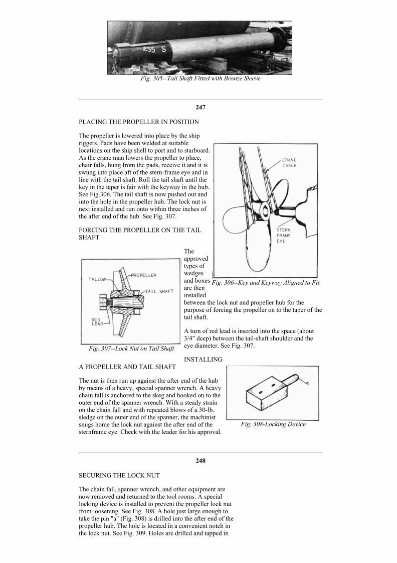
Fig. 306Key and Keyway Aligned to Fit.
Fig. 307Lock Nut on Tail Shaft
Fig. 308Locking Device
Fig. 305Tail Shaft Fitted with Bronze Sleeve
247
PLACING THE PROPELLER IN POSITION
The propeller is lowered into place by the shipriggers. Pads have been welded at suitablelocations on the ship shell to port and to starboard.As the crane man lowers the propeller to place,chair falls, hung from the pads, receive it and it isswung into place aft of the sternframe eye and inline with the tail shaft. Roll the tail shaft until thekey in the taper is fair with the keyway in the hub.See Fig.306. The tail shaft is now pushed out andinto the hole in the propeller hub. The lock nut isnext installed and run onto within three inches ofthe after end of the hub. See Fig. 307.
FORCING THE PROPELLER ON THE TAILSHAFT
Theapprovedtypes ofwedgesand boxesare theninstalledbetween the lock nut and propeller hub for thepurpose of forcing the propeller on to the taper of thetail shaft.
A turn of red lead is inserted into the space (about3/4" deep) between the tailshaft shoulder and theeye diameter. See Fig. 307.
INSTALLINGA PROPELLER AND TAIL SHAFT
The nut is then run up against the after end of the hubby means of a heavy, special spanner wrench. A heavychain fall is anchored to the skeg and hooked on to theouter end of the spanner wrench. With a steady strainon the chain fall and with repeated blows of a 30lb.sledge on the outer end of the spanner, the machinistsnugs home the lock nut against the after end of thesternframe eye. Check with the leader for his approval.
248
SECURING THE LOCK NUT
The chain fall, spanner wrench, and other equipment arenow removed and returned to the tool rooms. A speciallocking device is installed to prevent the propeller lock nutfrom loosening. See Fig. 308. A hole just large enough totake the pin "a" (Fig. 308) is drilled into the after end of thepropeller hub. The hole is located in a convenient notch inthe lock nut. See Fig. 309. Holes are drilled and tapped in
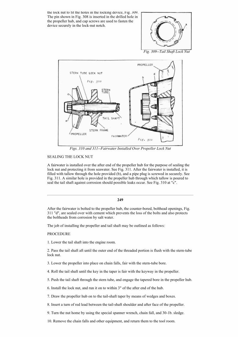
Fig. 309Tail Shaft Lock Nut
the lock nut to fit the holes in the locking device, Fig. 309.The pin shown in Fig. 308 is inserted in the drilled hole inthe propeller hub, and cap screws are used to fasten thedevice securely in the locknut notch.
Figs. 310 and 311Fairwater Installed Over Propeller Lock Nut
SEALING THE LOCK NUT
A fairwater is installed over the after end of the propeller hub for the purpose of sealing thelock nut and protecting it from seawater. See Fig. 311. After the fairwater is installed, it isfilled with tallow through the hole provided (b), and a pipe plug is screwed in securely. SeeFig. 311. A similar hole is provided in the propeller hub through which tallow is poured toseal the tail shaft against corrosion should possible leaks occur. See Fig. 310 at "c".
249
After the fairwater is bolted to the propeller hub, the counterbored, bolthead openings, Fig.311 "d", are sealed over with cement which prevents the loss of the bolts and also protectsthe boltheads from corrosion by salt water.
The job of installing the propeller and tail shaft may be outlined as follows:
PROCEDURE
1. Lower the tail shaft into the engine room.
2. Pass the tail shaft aft until the outer end of the threaded portion is flush with the sterntubelock nut.
3. Lower the propeller into place on chain falls, fair with the sterntube bore.
4. Roll the tail shaft until the key in the taper is fair with the keyway in the propeller.
5. Push the tail shaft through the stern tube, and engage the tapered bore in the propeller hub.
6. Install the lock nut, and run it on to within 3" of the after end of the hub.
7. Draw the propeller hub on to the tailshaft taper by means of wedges and boxes.
8. Insert a turn of red lead between the tailshaft shoulder and after face of the propeller.
9. Turn the nut home by using the special spanner wrench, chain fall, and 301b. sledge.
10. Remove the chain falls and other equipment, and return them to the tool room.

Fig. 312Docking Plug Assembly
11. Install the lock nut and lock key.
12. Install the fairwater.
13. Fill the fairwater recess and the propellerhub recess with tallow. Insert pipe plugs andmake tight.
14. Cement fairwater bolthead openings.
250
Launching a Tanker
GENERAL INFORMATION
The outside machinist has several important jobs to perform before a ship can be launched.Docking plugs must be screwed in place; the ship's rudder must be securely locked in acentral, foreandaft position and the propeller must be firmly held so that it cannot turn whenthe ship slides into the water. In the bottom of a tanker there are fortyseven docking plugs.See Fig. 312.
Metal flanges are threaded to fit the plugs shown inFig. 312. The flanges are welded in openings in theship's bottom.
PURPOSE OF DOCKING PLUGS
The openings are located in the bottom so thatevery tank in the ship may be drained through them.A docking plug is screwed into the threaded hole inthe flange before the ship is launched.
While the ship is on the ways and before thedocking plugs area finally screwed in place, lengthsof pipe equipped with valves, are temporarilyscrewed in place and the valves are closed. Thetanks are filled with water to test them for leaks.When the tanks have been tested and approved thevalves in the pipe lengths are opened and the wateris drained. The docking Plug is then screwed inplace by means of a wrench which fits the squarehole in the plug. See Fig. 312. When a ship isplaced in drydock the docking plugs are removed toallow all the water or other liquid in the tanks andbilge to drain. Oil tankers are washed out with livesteam and the accumulation of water and oil isdrained out through the docking plug openings.
LOCKING THE RUDDER
When the ship slides down the ways, See Fig. 313, there are several thousand tons of, deadweight to control after the ship is in the water. The rudder must be securely locked so that itcan not be slammed around by the water pressure as the ship leaves the ways. There are twoways by means of which this is accomplished:
251
1. SECURING RUDDER WHEN THE RUDDER STOCK IS INSTALLED
The riggers install cables at the stern of the ship. The cables are fastened from the rudder,port and starboard, to pads which are welded to the ship shell, port and starboard. The cablesare drawn up taut and made fast.

Fig. 314Chain Falls Attached
Tiller Jaws
Fig. 313The Ship Sliding Down the Ways
On the inside of the ship, Fig. 314, chain falls are fastened to the tiller jaws; one chain fall toport and one chain fall to starboard. The other end of each chain fall is fastened to the ship'sframe, port and starboard. The braces take the strain as the pull of the chain falls is exerted onthe tiller jaws. With the braces in place the chain falls are pulled up tight and locked, thusadding extra force inside the ship to assist the force of the cables installed outside of the shipby the riggers.
252
2. SECURING RUDDER WHEN THE RUDDERSTOCK IS NOT INSTALLED
Rudder stops are provided at the stern to prevent therudder from swinging more than 37 1/2 degrees toeither port or starboard. See Fig. 315.
When the rudder is in a central fore and aft positionthere is a space about 7 inches wide between therudder stops and the rudder bumpers. The riggersinstall cables at the stern of the ship as before. Withthe rudder held exactly fore and aft, R" to 1" thickplates about 7" wide are temporarily welded in thespace left between the rudder stops and the rudderbumpers. See Fig. 315. Whichever method is used,the work is supervised and Checked by the outsidemachinist.
HOLDING THE PROPELLER STATIONARY
The rush of water against the propeller as theship slides down the ways is sufficient to startthe propeller revolving. This must never beallowed to happen. Means must be provided tohold the propeller shaft and thus hold thepropeller. Fig. 316 shows a pair of heavy bars ofsteel which fit around the coupling flanges ofthe line shaft in the shaft alley. It will be notedthat the semicircular cutout in the center ofeach bar is for the purpose of allowing the barsto reach around the line shaft far enough for thebolts in the coupling flanges to pass through thebars.
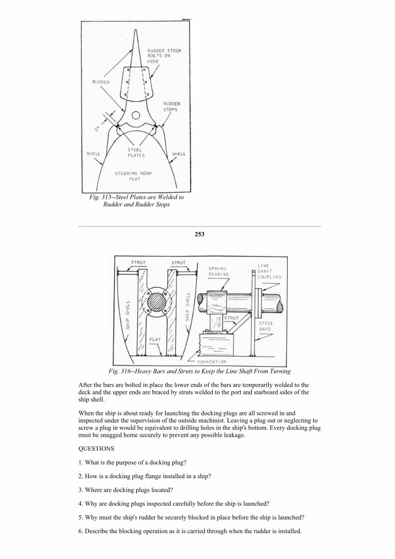
Fig. 315Steel Plates are Welded to
Rudder and Rudder Stops
253
Fig. 316Heavy Bars and Struts to Keep the Line Shaft From Turning
After the bars are bolted in place the lower ends of the bars are temporarily welded to thedeck and the upper ends are braced by struts welded to the port and starboard sides of theship shell.
When the ship is about ready for launching the docking plugs are all screwed in andinspected under the supervision of the outside machinist. Leaving a plug out or neglecting toscrew a plug in would be equivalent to drilling holes in the ship's bottom. Every docking plugmust be snugged home securely to prevent any possible leakage.
QUESTIONS
1. What is the purpose of a docking plug?
2. How is a docking plug flange installed in a ship?
3. Where are docking plugs located?
4. Why are docking plugs inspected carefully before the ship is launched?
5. Why must the ship's rudder be securely blocked in place before the ship is launched?
6. Describe the blocking operation as it is carried through when the rudder is installed.

7. Describe the blocking operation as it is carried through when the rudder stock is notinstalled.
8. Why must the ship's propeller be prevented from turning when the ship is launched?
9. Describe the method employed to lock the propeller in position while the ship is beinglaunched.
10. Make a list of the accidents and happenings that might take place if any of the duties ofthe outside machinist, as outlined in this lesson, were left undone.
254
This Page Blank.
Previous Part MachinistHome Page
Next Part
Copyright © 2013, Maritime Park Association. All Rights Reserved.
Legal Notices and Privacy Policy Version 3.00