
ShipConstructor - SSI · Select a ShipConstructor Database ... The Stocks Library 25 Overview ......
86
ShipConstructor By ARL - Albacore Research Ltd.
Transcript of ShipConstructor - SSI · Select a ShipConstructor Database ... The Stocks Library 25 Overview ......

ShipConstructor
By ARL - Albacore Research Ltd.

Albacore Research Ltd. License Agreement This is a legal agreement between the end-user and Albacore Research Ltd. By opening this package the user agrees to be bound by the terms of this agreement. If the user does not agree to the terms he should promptly return this package including all accompanying items to the place where it was obtained for a full refund.
1. Grant of License: The licensee receives a license for unlimited use on a single user system. 2. Copyright: The program remains the exclusive property of Albacore Research Ltd. and is protected by copyright laws. You may make copies of the software for back-up purposes or for transfer to hard disks, provided that one copy is only used at any time. You may not copy the written material accompanying the software. 3. Limited Warranty: Albacore Research Ltd. warrants that the software will perform substantially in accordance with the accompanying written materials for a period of 90 days from date of receipt. In some countries the warranty period may be different.
ALTHOUGH THE SOFTWARE HAS BEEN TESTED AND THE DOCUMENTATION HAS BEEN REVIEWED, ALBACORE RESEARCH LTD. MAKES NO WARRANTY EXPRESSED OR IMPLIED, WITH RESPECT TO THIS SOFTWARE, ITS QUALITY, PERFORMANCE, OR FITNESS FOR A PARTICULAR PURPOSE. THIS SOFTWARE IS SOLD “AS IS” AND YOU, THE PURCHASER, ARE ASSUMING THE ENTIRE RISK AS TO ITS QUALITY AND PERFORMANCE. IN NO EVENT WILL ALBACORE RESEARCH LTD. BE LIABLE FOR ANY DAMAGES WHATSOEVER (INCLUDING, WITHOUT LIMITATION, DAMAGES FOR LOSS OF BUSINESS PROFITS, BUSINESS INTERRUPTION, LOSS OF BUSINESS INFORMATION OR OTHER PECUNIARY LOSS, DAMAGES TO EQUIPMENT, MATERIAL AND PERSONS) ARISING OUT OF THE USE OR INABILITY TO USE THIS SOFTWARE PRODUCT. THE WARRANTY SET ABOVE IS IN LIEU OF ALL OTHERS, ORAL OR WRITTEN, EXPRESSED OR IMPLIED. October 01
ShipConstructor Team
Rolf Oetter Doug Dark Jason Paterson Chris Phillips Darren Larkins Walter Langer Eric Heemskerk Silke Sommerfeld Christian Zuger Adam Chernenkoff Terry Fiddler Lorne Trudeau Barinder Basi David Claus Lyndon Crossman James DeGreef Brian Oraas Shawn Stapleton Sue Stevens Kevin Van Donkersgoed Vlad Vukomanovic Mike Werner
4196 Kashtan Place Victoria, BC Canada V8X 4L7 Toll Free: Phone: Fax:
1-888-210-7420 1-250-479-3638 1-250-479-0868
[email protected] [email protected]
[email protected] www.ShipConstructor.com

ShipConstructor2001 Manager Contents •••• i
Contents
Manager 1 Overview....................................................................................................................................1
About Manager ............................................................................................................1
Opening a Project 3 Options .......................................................................................................................................3
Select a ShipConstructor Project..................................................................................3 Recent ShipConstructor Projects .................................................................................3 Select a ShipConstructor Database ..............................................................................4 Changing the Current Project.......................................................................................4
User Management 5 User Editing ...............................................................................................................................5
User Configurations .....................................................................................................6 Changing Password for the Current User...................................................................................6
Project Settings 9 Overview....................................................................................................................................9
The Units Tab ..............................................................................................................9 The Colors Tab ..........................................................................................................10 The Parts Tab.............................................................................................................11 The Symbols Tab .......................................................................................................12 The Flange Tab ..........................................................................................................13 The Nesting Tab.........................................................................................................14 The Reports Tab.........................................................................................................15 The Misc. Tab............................................................................................................15 The Pipe Colors Tab ..................................................................................................16
Project Database Management 17 Database Utilities .....................................................................................................................17
Database Manager......................................................................................................17 Copy...........................................................................................................................18 Delete.........................................................................................................................18 Backup .......................................................................................................................19 Restore .......................................................................................................................19 Import ........................................................................................................................20 Update........................................................................................................................21 Shrink.........................................................................................................................22 Schedule.....................................................................................................................22 Compare.....................................................................................................................23 Show Raw Data .........................................................................................................24

ii •••• Contents ShipConstructor2001 Manager
The Stocks Library 25 Overview..................................................................................................................................25
Creating a New Stock ................................................................................................26 Editing an Existing Stock...........................................................................................26 Deleting an Existing Stock.........................................................................................26 Defining Plate Sizes...................................................................................................26 Creating or Editing Outfit Types ...............................................................................27
The Endcuts Library 29 Overview..................................................................................................................................29
Editing an Existing Endcut ........................................................................................30 Deleting an Existing Endcut ......................................................................................30 Creating a New Endcut ..............................................................................................30 About Endcut Properties ............................................................................................30
The Flange Library 33 Overview..................................................................................................................................33
Editing an Existing Flange.........................................................................................34 Deleting an Existing Flange.......................................................................................34 Creating a New Flange ..............................................................................................34
The Materials Library 35 Overview..................................................................................................................................35
Editing an Existing Material ......................................................................................35 Delete an Existing Material .......................................................................................36 Creating a New Material ............................................................................................36
The Paints Library 37 Overview..................................................................................................................................37
Editing an Existing Paint ...........................................................................................37 Deleting an Existing Paint .........................................................................................38 Creating a New Paint .................................................................................................38
The NC Machines Library 39 Overview..................................................................................................................................39
Editing an Existing NC Machine ...............................................................................40 Deleting an Existing NC Machine .............................................................................40 Creating a New NC Machine .....................................................................................40
Bill of Materials 41 Overview..................................................................................................................................41
Creating a New BOM ................................................................................................41 Editing an Existing BOM...........................................................................................42 Available BOM Properties.........................................................................................43 Assembly BOM Examples.........................................................................................43 BOM Display.............................................................................................................45 Assigning BOMs and Template Drawings ................................................................46
Generating Reports 47 Overview..................................................................................................................................47

ShipConstructor2001 Manager Contents •••• iii
PWBS and SWBS Reports.........................................................................................47 Nesting.......................................................................................................................47
The Crystal Reports Interface ..................................................................................................47 The Toolbar ...............................................................................................................47 The TreeView ............................................................................................................48
PWBS.......................................................................................................................................49 PWBS Assembly Properties ......................................................................................50 PWBS Part Properties................................................................................................51 PWBS Report Options ...............................................................................................52
SWBS.......................................................................................................................................53 SWBS Report Options ...............................................................................................54
PWBS Parts Overview .............................................................................................................55 Nesting Reports........................................................................................................................56
Overview....................................................................................................................56 Nest Report Options...................................................................................................57 Stock Changed Parts Report ......................................................................................57
Common Tasks 59 Upgrading a ShipConstructor2000 Project...............................................................................59
Step 1 - Create a New Database.................................................................................59 Step 2 - Import the Data.............................................................................................59 Step 3 - Create the Project File ..................................................................................59
Transferring a Project to Another Server .................................................................................60 Step 1 – Backup the Database....................................................................................60 Step 2 – Package the project ......................................................................................60 Step 3 – Copy the Project to the Project Folder .........................................................60 Step 4 - Create a New Database.................................................................................60 Step 5 - Import the Data.............................................................................................60 Step 6 – Register to the Project in ShipConstructor...................................................60
Exporting a Report ...................................................................................................................61 Overview....................................................................................................................61 Exporting to Excel, Word or Similar Applications ....................................................61
Appendix 63 A. PWBS Example Reports .....................................................................................................63
A1. Build Strategy .....................................................................................................63 A2. Profile Report......................................................................................................65 A3. Standard Part Report ...........................................................................................67 A4. Pipe Stock ...........................................................................................................69 A5. Pipe Penetration ..................................................................................................71
B. SWBS Example Reports......................................................................................................72 B1. Pipe Stock ...........................................................................................................72 B2. Pipe Penetration ..................................................................................................74
C. Nesting Example Reports ....................................................................................................75 C1. Standard Nest Report ..........................................................................................75 C2. Stock Changed Parts Report Example.................................................................77
Index 79


ShipConstructor2001 Manager Contents •••• 1
Manager
Overview This manual outlines the project maintenance and reporting features included in ShipConstructor - Manager. This product was designed specifically to replace the outdated MS Access based ShipReport application which was included with previous versions of ShipConstructor. It affords all levels of ShipConstructor users with flexible project management and data-driven reporting capabilities. These capabilities are directly tied into the new SQL Server database management system (DBMS) that is at the heart of the ShipConstructor2001 suite of tools.
About Manager The About Manager dialog gives the user information about Manager and about the current project. To open the dialog, select the About Manager2001 option from the Help menu.


ShipConstructor2001 Manager Contents •••• 3
Opening a Project
Options The dialog below shows the various ways in which you can connect to a ShipConstructor2001 project when using Manager.
Select a ShipConstructor Project Selecting the “Select a ShipConstructor Project” option will open a standard Windows browse dialog that allows you to find the ShipConstructor project to which you would like to connect. By selecting the “.pro” file that can be found in the project folder you inform Manager that you want to open this project. You will then be asked to provide a username and password for the project that has been selected. Once a valid username and password have been provided, Manager will be connected to the project and work can continue.
Recent ShipConstructor Projects Selecting the “Recent ShipConstructor Projects” option allows you to select from the five most recent projects to which Manager has been successfully connected. By double clicking on one of the project files in the list, or alternatively by selecting an item and clicking OK, Manager will be connected to that project without you having to browse for a project file. You must still provide a valid username and password for the project that has been selected.
4 •••• Opening a Project ShipConstructor2001 Manager
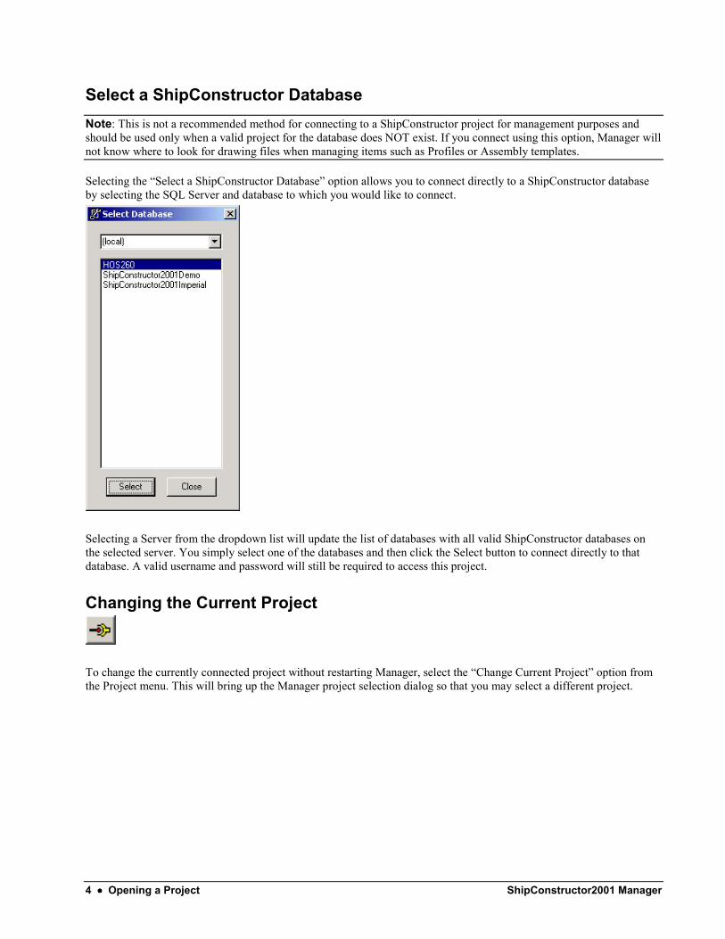
Select a ShipConstructor Database Note: This is not a recommended method for connecting to a ShipConstructor project for management purposes and should be used only when a valid project for the database does NOT exist. If you connect using this option, Manager will not know where to look for drawing files when managing items such as Profiles or Assembly templates.
Selecting the “Select a ShipConstructor Database” option allows you to connect directly to a ShipConstructor database by selecting the SQL Server and database to which you would like to connect.
Selecting a Server from the dropdown list will update the list of databases with all valid ShipConstructor databases on the selected server. You simply select one of the databases and then click the Select button to connect directly to that database. A valid username and password will still be required to access this project.
Changing the Current Project
To change the currently connected project without restarting Manager, select the “Change Current Project” option from the Project menu. This will bring up the Manager project selection dialog so that you may select a different project.

ShipConstructor2001 Manager Contents •••• 5
User Management
User Editing
New to ShipConstructor2001 is the ability to specify the actions that an individual user can perform. To begin managing users, select the “User Manager…” option from the Project menu.
This will open a dialog from which you can create a new user or select an individual user to edit or delete.
Selecting a user and then clicking the Delete button will remove the selected user from the project. Clicking the New or Edit buttons will start the User Management dialog shown below.

6 •••• User Management ShipConstructor2001 Manager
Select the permissions you would like the user to have in the tree on the right hand side of the dialog and then click OK to save the changes you have made to this user. If this is a new user the user will be created with the permissions that have been selected. For information on how to save this configuration of permissions for later user in creating and editing users see the next section on configurations.
User Configurations
Creating a User Configuration To create a user configuration, edit or create a user with the permissions you would like to save for later use. Once this has been completed enter a unique name for the configuration that you are creating in the Configuration Options dropdown list and then click the Save Configuration button. In this manner you can create configurations for the different departments and categories of designers who will be working on the project. This way you won’t have to manually set the options for each subsequent user you would like to create.
Loading a User Configuration To load a previously saved configuration into the user you are currently editing or creating, select the configuration from the dropdown list under Configuration Options. Click the Load Configuration button to load the selected configuration into the current user’s settings. The tree on the right will be updated to reflect the loaded configuration. Click OK to save the changes.
Changing Password for the Current User

ShipConstructor2001 Manager Contents •••• 7
Not all users will have permission to use the User Management functions in Manager. For this reason, the currently logged in user can change their password by selecting “Change Password…” from the Project menu.
Enter and confirm the new password and then click OK. This will change the password for the current user.

8 •••• User Management ShipConstructor2001 Manager

ShipConstructor2001 Manager Contents •••• 9
Project Settings
Overview
Project settings can be viewed and changed by selecting the “Project Settings” option on the Project menu.
The different settings have been organized into related groups and place on separate tabs for your convenience. It is not recommended that you change the project units or color settings for the project after any work has begun. The majority of these settings should be set before work has begun on the project.
If you change any of these settings while in a current ShipConstructor session, you will need to run Reload DB from the Navigator / 3D Unit tab.
The Units Tab The Units tab allows you to set the type of units for the project and the display units for the reports you will be generating in Manager.

10 •••• Project Settings ShipConstructor2001 Manager
Project Units – You should only change this at the very beginning of a project. This setting is determined by what units that the geometry will be drafted in AutoCAD. Report Units – These settings allow you to generate reports and BOMs in different units. ShipConstructor and Manager automatically convert the raw data to the desired units. These settings do not affect the raw data in anyway so changing them at anytime has no lasting effects. The checkbox beneath the settings for units determines whether or not to display imperial units in a standard feet and inches format.
The Colors Tab The Colors tab allows you to specify the different process colors used in ShipConstructor. The colors allow you to visually differentiate between things like inside cuts, outside cuts and marking lines on plate parts.
Example Part Colors:

ShipConstructor2001 Manager Contents •••• 11
The Parts Tab The Parts tab allows you to define conventions for the naming of parts and allows you to set which of the colors to use for piecemarks. It also allows you to set options for the text format of piecemarks.
Part Name Format The part name consists of 2 portions, the prefix and the autonumber. The prefix is determined by this setting. The autonumber is a 3 digit number that is the next available number to make the partname unique. Prefix Conventions From Drawing Name – Parts are named according to the group drawing that they are in. Last Created – Parts contain the same prefix as the last part entered. Custom – Parts are named according the assembly is belongs to. Clicking the “…” button allows you to specify a customized part naming convention as shown below.

12 •••• Project Settings ShipConstructor2001 Manager
As you change the options in the dialog a sample part name will be generated (only if assemblies at those levels actually exist). The part name can be constructed from a selection of characters from the assemblies and sub-assemblies to which it belongs. The included characters are determined by entering a valid range format in the range textbox below the dropdown for selecting the PWBS level at each stage. A valid range format consists of a series of numbers. The numbers correspond with the characters to include and the order in which to include them. For example, a 4 in the range box signifies that each part name should contain the fourth character (and only the fourth character) from the PWBS level selected in the dropdown above the range box. This is useful if your Units are named sequentially such as [Unit1……UnitX] and you wish the part name to only include the number from the unit. Any parts belonging in Unit3 would be named starting with a 3 and followed by the character specified in the next “Sep:” textbox. Part Side in Part Name – The part’s side is shown at the end of the part name: P for port, S for starboard, PS for port/starboard, C for center. Part Type in Part Name – Inserts a charater to identify the type of part in the partname: P for plate, S for stiffener, F for faceplate. The character appears before the autonumber. Base numbering – Some companies prefer to have a specific range of autonumbers that a parttype can have. The base numbering lets you select the first autonumber that the part of that type will have. For Example, if you want your stiffener part numbers to be ABC-500, ABC-501, … then set the stiffener base numbering to 500. Piecemark Color – This determines if you will be marking the piecemark on plate parts when they are cut. Std Part as no process – This lets you have a different process setting for standard parts. Check this box if you mark the piecemark on your regular plate parts but do not want to mark them on standard parts. Text Size – The default size of a piecemark. This setting can be changed when the part is created. Plate Bubble – The bubble is a rectangle with 2 semi-circles on the sizes to identify the text inside as being the piecemark and not just a note. Some users prefer not to have the bubble on plate parts because it can take up time to mark it. Extrusions Bubble – Check this if you want to have a bubble around the stiffener and faceplate parts. This is just for esthetics. Dup. Piecemark – A duplicate piecemark is a piecemark of a stiffener or faceplate attached to a plate part that you want to show on the plate part. This setting allows you to either mark that on the plate or not. This color change occurs when the part is exported to NC-Pyros.
The Symbols Tab The Symbols tab allows you to set certain options associated with the size and presentation of some of the symbols in ShipConstructor.

ShipConstructor2001 Manager Contents •••• 13
The color allows you to select whether you would like to use the Marking or No Processing color that you have selected on the Color Tab. The size options allow you to specify a scale factor for the group marking text and thickness throw symbol in ShipConstructor. Selecting 1 signifies no scaling, while settings of less than or greater than 1 signify a decrease or increase of the standard size respectively. The Linetype Scale textbox allows you to specify a scaling factor for the weight of the lines used to draw the symbols.
The Flange Tab The Flange tab allows you to specify several options for how flanges and the markings for flanges are displayed in ShipConstructor.
The Shorten Fold Line option allows you to set how many units the marking line is inset from the edge of the plate. This is desirable due to the potential for a plate to crack at the edges while bending along the fold line if the marking line extends to the edges. This is a default setting and the actual values for a specific flange can be changed

14 •••• Project Settings ShipConstructor2001 Manager
The text size and symbol size options allow you to set the size of the marking symbols for the flange.
The Nesting Tab The Nesting tab allows you to set how parts are displayed in a nest drawing before they have been assigned to a nest. Once the parts have been assigned to a nest they will take the colors set on the Colors Tab. This allows you to visually differentiate between the parts that have been assigned to a nest and those that are just in the nest drawing waiting to be nested.
This tab also allows you to determine how the name of a nest is determined. The custom option allows you to override the default options and set your own name prefix each time.

ShipConstructor2001 Manager Contents •••• 15
The Reports Tab The Reports tab allows you to set how the headers and title pages of the reports you generate in Manager will contain.
The Misc. Tab The Misc. tab allows you to set the tolerances and preferences for certain settings in ShipConstructor.
Snap Tolerance – Tolerance used by the toolpath command in ShipConstructor. Lines separated by any distance less than this number are joined. Minimum Interference Volume – Volume used to filter out very small interferences from an interference check. This value is in the report units on the units tab. Solid Creation Tolerance – This setting allows you to determine how accurate solids in ShipConstructor are. If this setting is 0 then the solids will exactly match the production geometry. This can sometimes generate AutoCAD ACIS errors due to complexity and will make the solids more complex than they need to be. The solids in ShipConstructor are only used for visual representation, weights and cg and interference checking and not actually production. Therefore their accuracy can be reduced to reduce file size and lessen the chance of ACIS errors.

16 •••• Project Settings ShipConstructor2001 Manager
Faceplate Bend Tolerance - This value determines the angle at which a curved faceplate is determined to have a bend. A curved faceplate in ShipConstructor is represented by a polyline will small straight line segments. When the polylines segments change direction by the tolerance degree or more than a bend is reported. The value is in degrees.
The Pipe Colors Tab The Pipe Colors tab allows you to specify how pipes are drawn in ShipConstructor.
Below is an example of how the color settings will affect the displayed piping entities in ShipConstructor.
ShipConstructor2001 Manager Contents •••• 17
Project Database Management
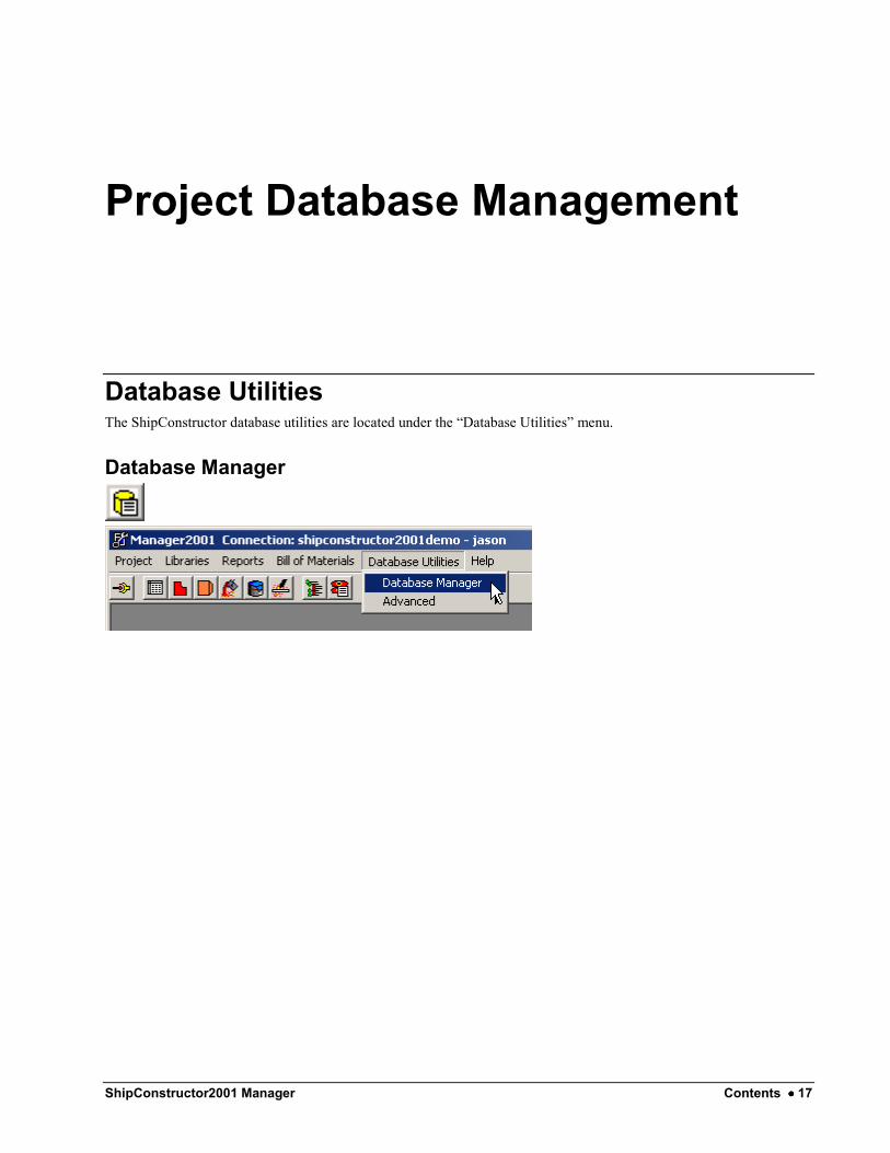
Database Utilities The ShipConstructor database utilities are located under the “Database Utilities” menu.
Database Manager

18 •••• Project Database Management ShipConstructor2001 Manager
Copy Selecting the Copy function will allow you to create a copy of a project database that is selected in the Database list. It can only copy a database to the same SQL server.
Type a name for the new database and click the Copy button to continue. An exact copy of the selected database will be created with the new name that was entered.
Delete Selecting the Delete function will allow you to delete a project database. The data in the database will be unrecoverable once the database is deleted. Select the database you wish to delete then click the Delete button to permanently delete the database.
ShipConstructor2001 Manager Contents •••• 19
Backup Selecting Backup function will make a backup file of a project database to ensure that you have a secure backup of your project data in the unlikely event of data corruption or hardware failure. The backup file will be place in a folder named “Backup” in the SQL Server installation directory. The default location for the backup files is: “C:\Program Files\Microsoft SQL Server\MSSQL\Backup”. The backup file will be named in the following manner:
<YOUR PROJECT NAME> + <Current Date/Time> + .bak
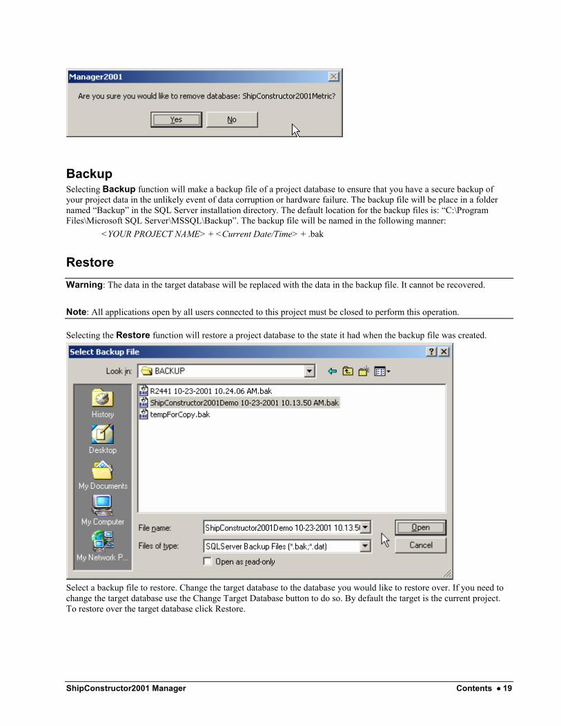
Restore Warning: The data in the target database will be replaced with the data in the backup file. It cannot be recovered.
Note: All applications open by all users connected to this project must be closed to perform this operation.
Selecting the Restore function will restore a project database to the state it had when the backup file was created.
Select a backup file to restore. Change the target database to the database you would like to restore over. If you need to change the target database use the Change Target Database button to do so. By default the target is the current project. To restore over the target database click Restore.

20 •••• Project Database Management ShipConstructor2001 Manager
Import Warning: The data in the selected database will be replaced with the data in the picked database file.
Selecting Import allows you to import the data from either an existing ShipConstructor2000 project or from an existing ShipConstructor2001 project. All importing is done into the currently connected project. Ensure that you are connected to the project you want to import INTO before beginning the process.
MS Access Import (ShipConstructor2000)
Selecting the MS Access option will change the dialog to look like the one above. Select an MS Access database (*.mdb) file using the Select Source Database button. Click the Import button to begin.

ShipConstructor2001 Manager Contents •••• 21
SQL Server Import (ShipConstructor2001)
Selecting the SQL Server option will change the import dialog to look like the one above. Selecting a SQL Server from the dropdown list will update the list of ShipConstructor databases on that server. Select a database from the list and then click the Import button to continue.
Update Note: All applications open by all users connected to this project must be closed to perform this operation.
Selecting the Update function will allow you to update the structure of the currently connected database to the structure contained in a selected SQL Server backup file. This option is generally only used when changes are made to the internal structure of the database and an existing project needs to be updated to this version. When you receive a database update from ARL this option will allow you to incorporate our latest changes into your ongoing project.
To perform an update, connect to the project you wish to update and then select Update Current Database from the Database Utilities menu. Locate the backup file containing the newer structure using the Select Backup File… button.
22 •••• Project Database Management ShipConstructor2001 Manager
Click the Update button to begin the update. If this update fails for any reason the current database could be left in an unknown and potentially unusable state. For this reason, the Update automatically creates a backup of the current database in the default location (see the Backup Database section above for more information). Restoring from this backup file will restore the project database to the state it was in before the Update operation was attempted.
Shrink Selecting the Shrink function will shrink the size of the database by removing any unused data pages and shrink the transaction log file. Consult your SQL Server documentation for further explanation.
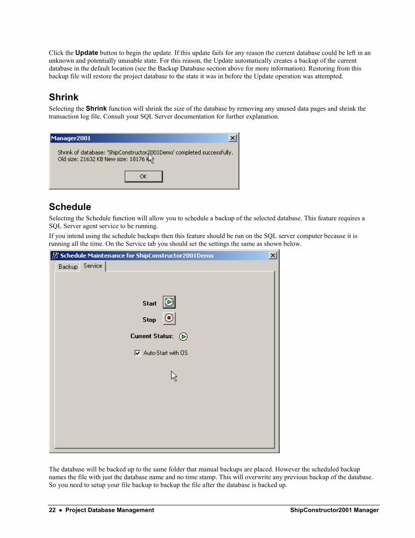
Schedule Selecting the Schedule function will allow you to schedule a backup of the selected database. This feature requires a SQL Server agent service to be running. If you intend using the schedule backups then this feature should be run on the SQL server computer because it is running all the time. On the Service tab you should set the settings the same as shown below.
The database will be backed up to the same folder that manual backups are placed. However the scheduled backup names the file with just the database name and no time stamp. This will overwrite any previous backup of the database. So you need to setup your file backup to backup the file after the database is backed up.

ShipConstructor2001 Manager Contents •••• 23
Compare Selecting the “Compare” option from the Database Utilities menu will allow you to perform a comparison of the structure and the data contained within 2 separate ShipConstructor databases. This utility is mainly used for diagnosing problems and will likely not be used by most users.
Select the server that contains the two databases you wish to compare. Select the both databases and then click the Compare Structure button to compare the two databases. Any differences will be listed for you.
24 •••• Project Database Management ShipConstructor2001 Manager
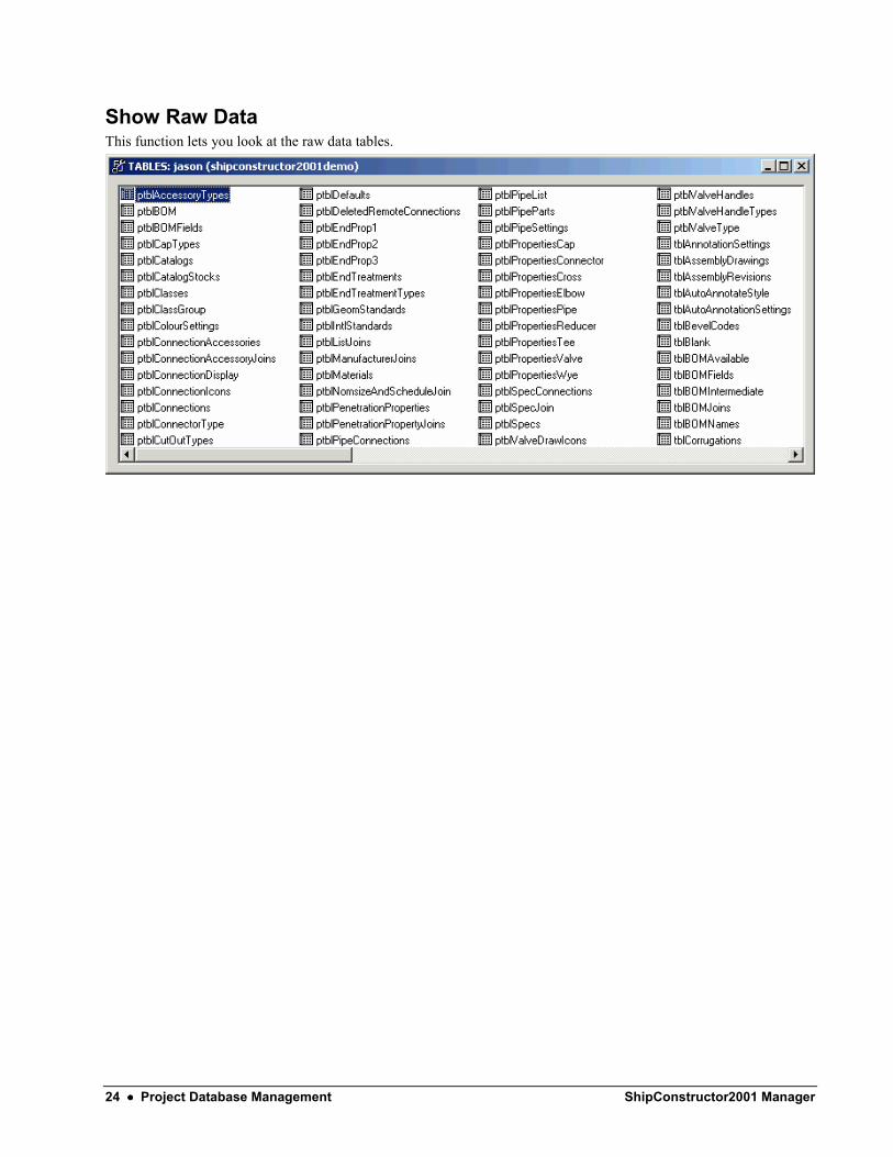
Show Raw Data This function lets you look at the raw data tables.
ShipConstructor2001 Manager Contents •••• 25
The Stocks Library
Overview
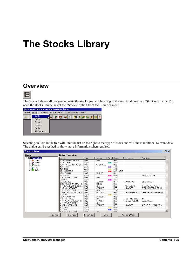
The Stocks Library allows you to create the stocks you will be using in the structural portion of ShipConstructor. To open the stocks library, select the “Stocks” option from the Libraries menu.
Selecting an item in the tree will limit the list on the right to that type of stock and will show additional relevant data. The dialog can be resized to show more information when required.

26 •••• The Stocks Library ShipConstructor2001 Manager
To obtain a listing of all structural parts currently using a given stock, select the stock and click the Parts Using Stock button on the lower right of the Stocks Library dialog.
Creating a New Stock To create a new stock in Manager, click the New Stock button on the Stocks Library dialog. Enter a name and then select a type for the new stock. Changing the stock type will alter the properties available to you. Fill in the data appropriate to the new stock and click OK to create the stock. Clicking the Cancel button will return you to the Stocks Library without creating the new stock.
Editing an Existing Stock To edit an existing stock in Manager, select the stock in the Stocks Library and then click the Edit Stock button. Change any of the stock properties you wish and then click OK to confirm the changes. Clicking the Cancel button will return you to the Stocks Library and no changes will be made to the selected stock.
Deleting an Existing Stock To delete an existing stock, select the stock in the Stocks Library and click the Delete Stock button. A stock can only be deleted if there are no parts currently using the stock. To delete a stock if it is in use, remove any parts that are using this stock and then attempt to delete the stock again.
Defining Plate Sizes After a plate stock is created you will most likely wish to define a set of available plate sizes for that stock. To accomplish this task, edit the plate stock for which you would like to define the new sizes. Towards the bottom of the edit dialog you will see a section that looks like the one shown here. This section allows you to define, edit and remove plate sizes for this stock.

ShipConstructor2001 Manager Contents •••• 27
Creating or Editing Outfit Types While you are editing an outfit stock you can change the type of the outfit. To change the type of the outfit select the new type from the dropdown list on the edit dialog.
If you wish to create a new outfit type or edit an existing type, click the Types… button below the dropdown list. In the Outfit Types dialog you can directly edit the types that are listed. Click the New button to create a new outfit type. To delete one of the types listed, select the type and then click the Delete button.

28 •••• The Stocks Library ShipConstructor2001 Manager

ShipConstructor2001 Manager Contents •••• 29
The Endcuts Library
Overview
The Endcuts Library will allow you to create, edit and delete endcuts that can later be applied to profile parts in ShipConstructor. Select “Endcuts” from the Libraries menu to open the endcuts library.
The Endcut Library appears as shown below.

30 •••• The Endcuts Library ShipConstructor2001 Manager
Editing an Existing Endcut To edit an existing endcut, select the endcut in the list on the left and then click the Edit On/Off button. This will enable the dialog for editing. Make any changes you wish to make to the endcut. To finish editing, select a different endcut, click the Edit On/Off button again, or close the Endcuts Library by clicking the Close button. For information about the available properties for an endcut see the Endcut Properties section below.
Deleting an Existing Endcut To delete an existing endcut, select the endcut in the list and then click the Delete button. If the endcut is in use by any parts in the project you will not be allowed to delete it. You must first delete the parts using the endcut and then attempt to delete the endcut again.
Creating a New Endcut To create a new endcut, click the New button. You will be prompted for a name for the new endcut.
Enter a name for the endcut and click OK. You can now edit the properties for the endcut. To finish the creation process, select another endcut in the list, click the Edit On/Off button, or close the endcuts library by clicking the Close button. For information about the available properties for an endcut see the Endcut Properties section below.
About Endcut Properties For an overview of the available endcut options click the Help button on the Endcut Library.
ShipConstructor2001 Manager Contents •••• 31
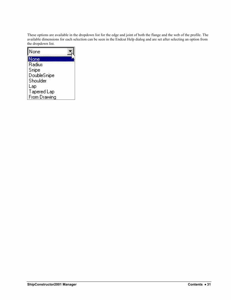
These options are available in the dropdown list for the edge and joint of both the flange and the web of the profile. The available dimensions for each selection can be seen in the Endcut Help dialog and are set after selecting an option from the dropdown list.

32 •••• The Endcuts Library ShipConstructor2001 Manager
ShipConstructor2001 Manager Contents •••• 33
The Flange Library
Overview
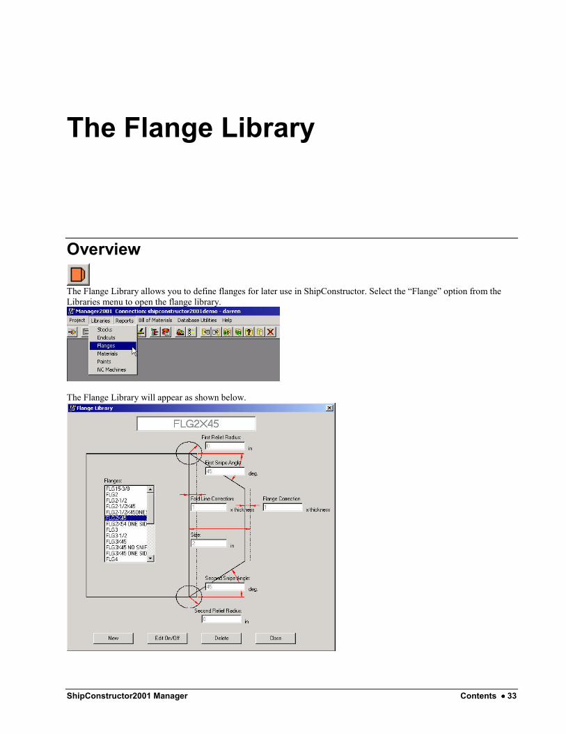
The Flange Library allows you to define flanges for later use in ShipConstructor. Select the “Flange” option from the Libraries menu to open the flange library.
The Flange Library will appear as shown below.

34 •••• The Flange Library ShipConstructor2001 Manager
Editing an Existing Flange To edit an existing flange select the flange from the list on the left of the dialog and click the Edit On/Off button. This will enable the dialog for editing and you can proceed to make changes to the flange. To finish editing the flange, click the Edit On/Off button, select another flange, or click the Close button to close the flange library.
Deleting an Existing Flange To delete an existing flange, select the flange in the list on the left and click the Delete button. You will be asked for confirmation before the flange will be deleted.
Click the Yes button to permanently delete the flange. Click No to cancel the delete operation.
Creating a New Flange To create a new flange, click the New button. You will be prompted for a name for the new flange.
Enter a name for the flange and then click OK. You can now edit the properties for the new flange. To finish editing the flange, click the Edit On/Off button, select another flange, or click the Close button to close the flange library.

ShipConstructor2001 Manager Contents •••• 35
The Materials Library
Overview
The Materials Library allows you to create, edit and delete materials to be later used when defining stocks in Manager. Selecting the “Materials” option from the Libraries will open the Materials Library.
The Materials Library will appear as shown below.
Editing an Existing Material To edit an existing material, select it from the list of materials and then click the Edit button. Change the properties for the material and then click OK to confirm the changes. Clicking the Cancel button will return you to the materials library without changing the material.

36 •••• The Materials Library ShipConstructor2001 Manager
Delete an Existing Material To delete an existing material, select it in the materials list and then click the delete button. You will not be allowed to delete a material if it is in use by any of the stocks and/or parts in this project. To remove the material, delete any parts using it and then try to delete it again.
Creating a New Material To create a new Material, click the New button on the materials library. Enter the properties for the new material and then click OK to create the material. Clicking Cancel will return you to the materials library without creating the new material.

ShipConstructor2001 Manager Contents •••• 37
The Paints Library
Overview
The Paints Library allows you to edit, create and delete the paints that are later assigned to parts and assemblies in ShipConstructor. To open the Paints Library, select the “Paints” option on the Libraries menu. These paints (or processes) are shown in reports and BOMs in ShipConstructor. The paint can also be used as a filter when nesting to be able to nest only parts with a certain paint.
The Paints Library will appear as shown below.
Editing an Existing Paint Existing paints can be edited directly by selecting the paint and changing the name in the Paints Library.

38 •••• The Paints Library ShipConstructor2001 Manager
Deleting an Existing Paint To delete an existing paint, select the paint in the list and click the Delete button. You will not be allowed to delete a paint that is in use by any parts or assemblies in the project. To delete a paint that is in use delete any parts or assemblies that are using the paint and then attempt to delete the paint again.
Creating a New Paint A new paint is created when you click the New button in the Paints Library. This will create a new paint with a generic name of the form “NewPaintX”. Change the name of the paint to something appropriate to finish the creation process.
ShipConstructor2001 Manager Contents •••• 39
The NC Machines Library
Overview
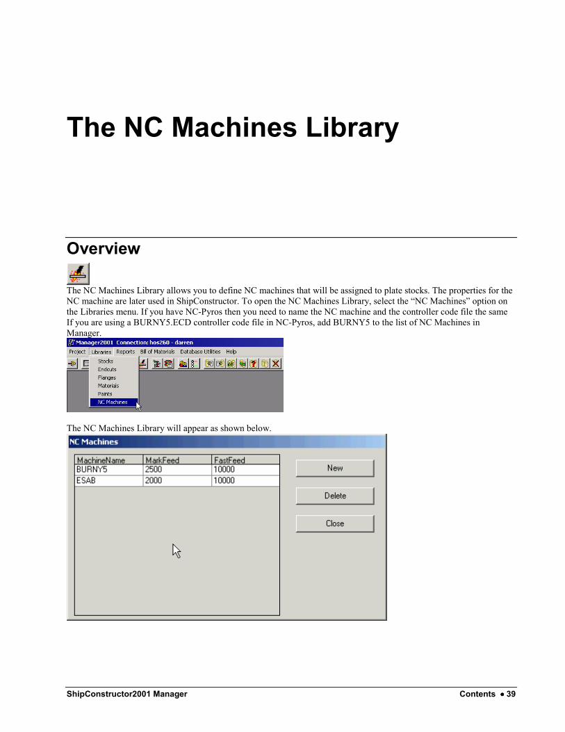
The NC Machines Library allows you to define NC machines that will be assigned to plate stocks. The properties for the NC machine are later used in ShipConstructor. To open the NC Machines Library, select the “NC Machines” option on the Libraries menu. If you have NC-Pyros then you need to name the NC machine and the controller code file the same If you are using a BURNY5.ECD controller code file in NC-Pyros, add BURNY5 to the list of NC Machines in Manager.
The NC Machines Library will appear as shown below.

40 •••• The NC Machines Library ShipConstructor2001 Manager
Editing an Existing NC Machine Existing machines can be edited directly by selecting the Machine and changing the properties in the NC machines library.
Deleting an Existing NC Machine To delete an existing NC machine, select it in the list and click the Delete button. You will not be allowed to delete a machine that has been assigned to a plate in the project. To delete a machine that is in use, delete any plates that are using the machine and then attempt to delete it again.
Creating a New NC Machine A new NC machine is created when you click the New button in the NC Machines Library. This will create a new machine with a generic name of the form “NewMachineX”. Change the name of the machine to something appropriate and set its properties accordingly to finish the creation process.

ShipConstructor2001 Manager Contents •••• 41
Bill of Materials
Overview In Manager, the Bill of Materials menu allows you to manage and configure the Assembly and Nest Drawing BOMs used in ShipConstructor. From this menu you can create, remove, and edit BOMs as well as assign BOMs and template drawings to PWBS assembly levels.
Creating a New BOM To create a new Bill of Materials, select the “Create BOM” option from the Bill of Materials menu.
The Create BOM dialog that appears will look like the one below.

42 •••• Bill of Materials ShipConstructor2001 Manager
Set the properties for the new BOM and add the fields you wish the BOM to contain. More information on the available properties can be found in the section below titled Available BOM Properties.
Editing an Existing BOM To edit an existing BOM select the “Edit BOM” option from the Bill of Materials menu.
In the following dialog select the BOM you wish to edit and click OK (or double-click).

ShipConstructor2001 Manager Contents •••• 43
The edit BOM dialog will be populated with the values from the BOM you are editing. Make any changes you wish and then click OK to save the changes or Cancel to discard the changes.
Available BOM Properties The available options for an Assembly BOM are: Name - The name of the new BOM. Rows Per Column - The number of rows displayed before moving to the next set of columns. AutoNumber Rows - Specifies whether or not the rows will be numbered sequentially. Include Sub-Assembly Parts - Specifies whether to include the parts in sub-assemblies of the selected assembly. Standard Parts by Quantity - Specifies whether or not standard parts are grouped and marked with the number of instances of the standard part. Standard Quantities by Assembly - Specifies whether or not the standard part groupings in the option above are sub-grouped by assembly. Chosen Fields - Only the fields in the Chosen Fields list will be included in the BOM. They will be included in the order they appear in the list.
Assembly BOM Examples Here are a few examples of Assembly BOMs generated in ShipConstructor and the options that were chosen.
Example 1 Selected Options - Rows per Column: 15, AutoNumber Rows: Yes, Standard Parts By Quantity: Yes Chosen Fields - Name, Stock, Throw, Length
44 •••• Bill of Materials ShipConstructor2001 Manager
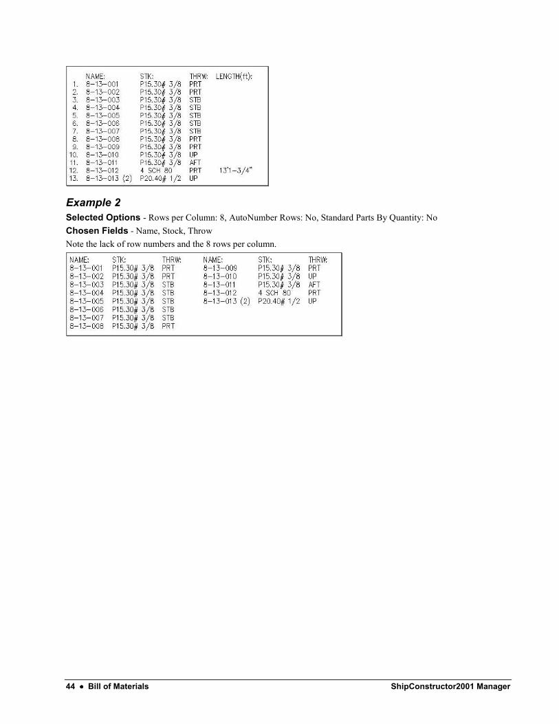
Example 2 Selected Options - Rows per Column: 8, AutoNumber Rows: No, Standard Parts By Quantity: No Chosen Fields - Name, Stock, Throw Note the lack of row numbers and the 8 rows per column.
ShipConstructor2001 Manager Contents •••• 45
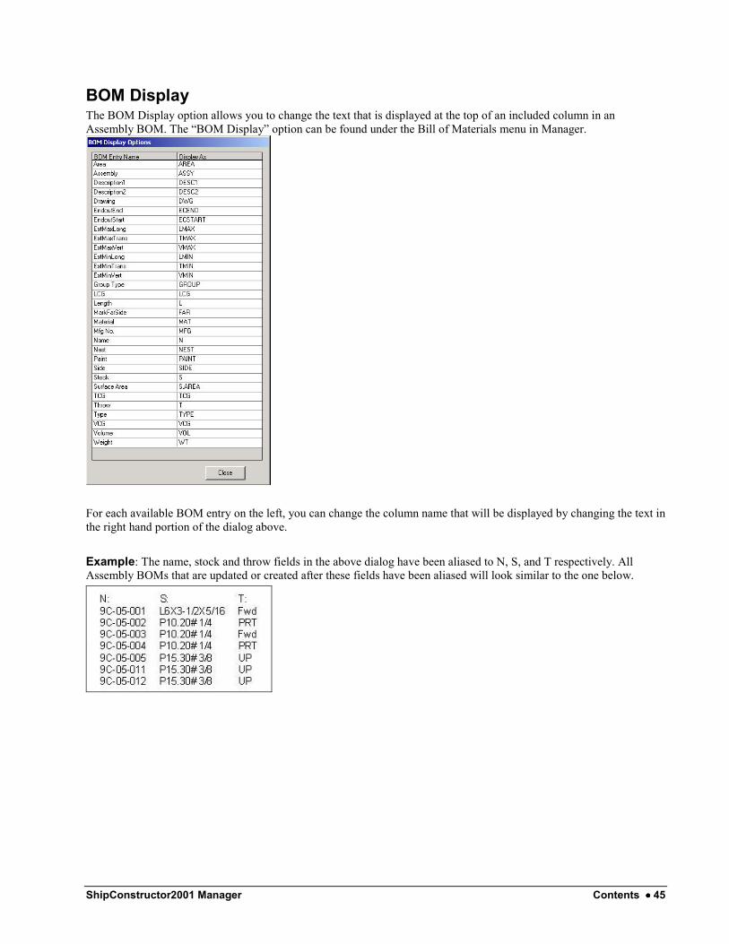
BOM Display The BOM Display option allows you to change the text that is displayed at the top of an included column in an Assembly BOM. The “BOM Display” option can be found under the Bill of Materials menu in Manager.
For each available BOM entry on the left, you can change the column name that will be displayed by changing the text in the right hand portion of the dialog above. Example: The name, stock and throw fields in the above dialog have been aliased to N, S, and T respectively. All Assembly BOMs that are updated or created after these fields have been aliased will look similar to the one below.

46 •••• Bill of Materials ShipConstructor2001 Manager
Assigning BOMs and Template Drawings For each PWBS level (i.e. Project, Unit etc.) you can assign a default BOM and template assembly drawing that will be used when generating assembly drawings in ShipConstructor.
Clicking on the Assigned BOM or Template Drawing field for a given PWBS Level in the above dialog will create a dropdown list from which you can select one of the available options. Close the dialog when you have finished making all required changes.

ShipConstructor2001 Manager Contents •••• 47
Generating Reports
Overview The reporting engine within Manager allows you to generate data centric reports based on the latest project information. Manager uses the Crystal Reports Engine from Seagate Software to provide you with flexible, functional, and fast reporting capabilities. Currently the reports are separated into two distinct categories: PWBS and SWBS and Nesting.
PWBS and SWBS Reports
Selecting the “PWBS and SWBS” option from the Reports menu allows you to generate reports based on the Product Work Breakdown Structure (PWBS) or System Work Breakdown Structure (SWBS) of the current project. This option also allows you to get a detailed listing of the properties of a PWBS assembly or structural part. The dialog also allows you to obtain a complete listing of all structural parts in the project.
Nesting
Selecting the “Nesting” option from the Reports menu allows you to generate reports based upon the nesting information in the current project. Nesting reports can be generated for the entire project, for a selected number of Units, or for a selected number of Nests. The reports contain information such as nest utilization, dimensions and the number of parts that have been nested on a particular plate.
The Crystal Reports Interface
The Toolbar

48 •••• Generating Reports ShipConstructor2001 Manager
1. Close Current View - If the user has opened one of the sub-reports internal to the current report this toolbar
button will be active. Clicking the button will close the current internal view. See the The TreeView section that follows this section for more information about sub-report views.
2. Print - Prints the current report. 3. Export - Allows the report to be exported to various other formats such as HTML, PDF etc…. 4. Toggle Group Tree - Turns the TreeView (see next section) on and off. 5. Zoom - Changes the viewable size of the report. 6. Page Selectors - Navigates the pages in the report or sub-report. 7. Find - Searches the report for text matching an entered value. 8. Busy - This image is animated when the report is busy formatting or processing data.
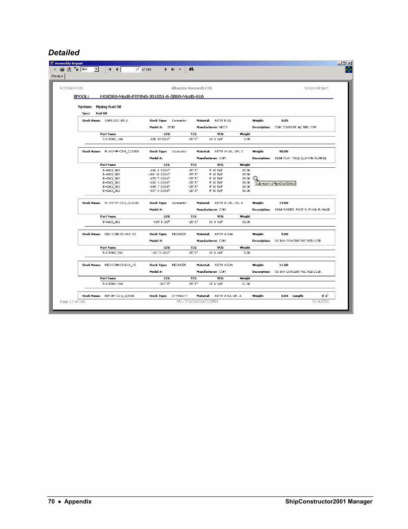
The TreeView The TreeView exists to the left of the report and can be toggled on and off by pressing the Toggle Group Tree toolbar button. The TreeView usually only contains useful information when you have entered a valid sub-report of the current report. To enter a sub-report (i.e. the detailed portion of a profile report) double-click anywhere on the main report when
the mouse pointer looks like this: . When the sub-report opens a new tab will appear in the TreeView. Navigating the TreeView and selecting one of the tree’s elements will automatically update your position in the report so that you are viewing the entry selected in the tree. To close the sub-report, click the Close Current View toolbar button.
ShipConstructor2001 Manager Contents •••• 49
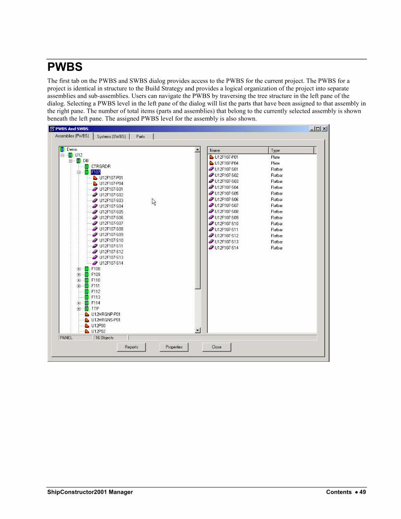
PWBS The first tab on the PWBS and SWBS dialog provides access to the PWBS for the current project. The PWBS for a project is identical in structure to the Build Strategy and provides a logical organization of the project into separate assemblies and sub-assemblies. Users can navigate the PWBS by traversing the tree structure in the left pane of the dialog. Selecting a PWBS level in the left pane of the dialog will list the parts that have been assigned to that assembly in the right pane. The number of total items (parts and assemblies) that belong to the currently selected assembly is shown beneath the left pane. The assigned PWBS level for the assembly is also shown.

50 •••• Generating Reports ShipConstructor2001 Manager
PWBS Assembly Properties Selecting a PWBS assembly ( ) in either pane of the PWBS dialog and then clicking the Properties button will show a listing of the totals for all parts assigned to that PWBS level. The properties include the weight, CG and part breakdown for the entire assembly. On this dialog you can change the paint that has been assigned to the assembly and can edit description fields that contain any additional information about the assembly that is required.

ShipConstructor2001 Manager Contents •••• 51
PWBS Part Properties Selecting a structural part ( ) in either pane of the PWBS dialog and then clicking the Properties button will display the properties for that part in a separate dialog.
From within this dialog you can change the assigned side for the part (limited by the transverse CG), the Stock used by the part, and the paint that has been assigned to the part. The bottom portion of the dialog shows a history of revisions that have been made to the part during its life cycle.

52 •••• Generating Reports ShipConstructor2001 Manager
PWBS Report Options Selecting an assembly in either pane of the PWBS dialog and then clicking the Reports button will allow you to generate one of the available reports based upon that PWBS assembly. Users may select the level of detail and output size for the report, as well as grouping options where applicable. The grouping options condense multiple rows that contain some identical data into a single entry. The total parts that the entry reflects are listed along with any data that may be important to the grouping as a whole.
The PWBS reports that are available in Manager are: • Build Strategy (Appendix A1) - Generates an expanded view of the Build Strategy for the project including
parts and/or assemblies. Parts totals and properties for each assembly are shown with the assembly. • Profile (Appendix A2) - Generates a report outlining all the profile parts and applicable production information
that have been assigned to the assembly. • Standard Part (Appendix A3) - Generates a report showing all the standard parts in the assembly, including the
location in the assembly hierarchy. • Pipe Stock (Appendix A4) - Generates a report outlining the pipe stocks that belong to spools that have been
assigned to the selected assembly. • Pipe Penetration (Appendix A5) - Generates a report showing detailed information for all pipe penetrations that
exist in part solids that belong to the selected assembly.

ShipConstructor2001 Manager Contents •••• 53
SWBS The second tab on the PWBS and SWBS dialog provides access to the SWBS for the current project. The SWBS for a project provides a logical organization of the project into separate systems and branches. Users can navigate the SWBS by traversing the tree structure in the left pane of the dialog. Selecting a SWBS level in the left pane of the dialog will list the components and branches that have been assigned to that system in the right pane. The number of total items (components and branches) that belong to the currently selected system is shown beneath the left pane. The name of the selected SWBS level or the name of the selected component is also shown.
54 •••• Generating Reports ShipConstructor2001 Manager
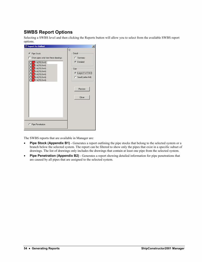
SWBS Report Options Selecting a SWBS level and then clicking the Reports button will allow you to select from the available SWBS report options.
The SWBS reports that are available in Manager are: • Pipe Stock (Appendix B1) - Generates a report outlining the pipe stocks that belong to the selected system or a
branch below the selected system. The report can be filtered to show only the pipes that exist in a specific subset of drawings. The list of drawings only includes the drawings that contain at least one pipe from the selected system.
• Pipe Penetration (Appendix B2) - Generates a report showing detailed information for pipe penetrations that are caused by all pipes that are assigned to the selected system.

ShipConstructor2001 Manager Contents •••• 55
PWBS Parts Overview The Parts tab in the PWBS and SWBS dialog allows you to get a listing of every part in the project. To get a more comprehensive view of one of the parts click the Detailed Properties button (or double-click) after selecting the desired part. The properties for the selected part will be shown in the same fashion as in the PWBS Part Properties section above.
56 •••• Generating Reports ShipConstructor2001 Manager
Nesting Reports
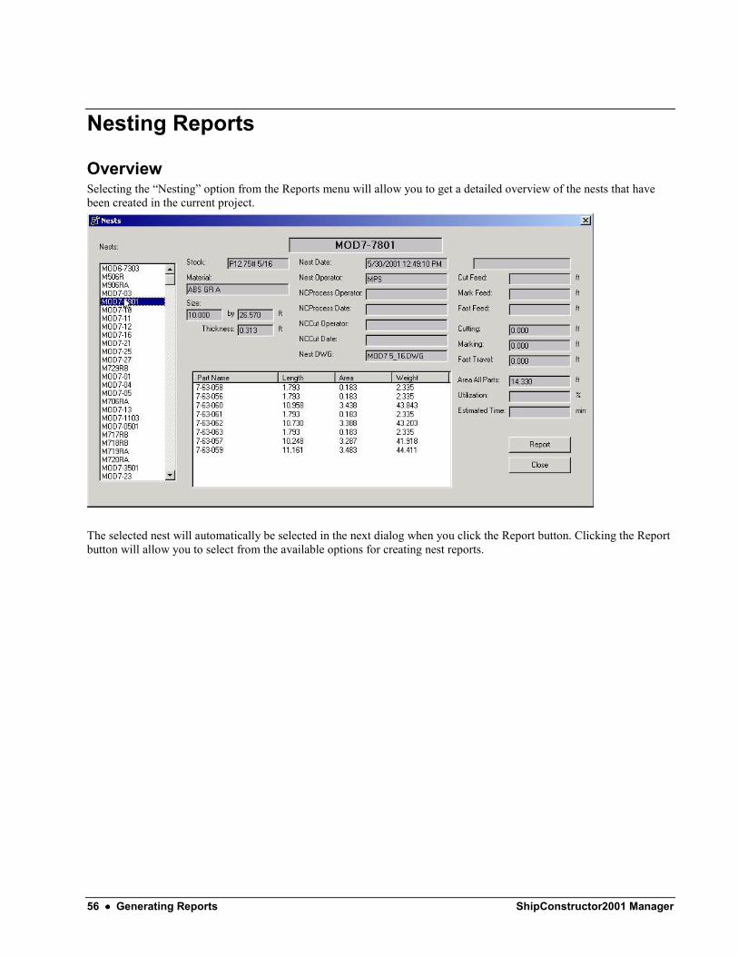
Overview Selecting the “Nesting” option from the Reports menu will allow you to get a detailed overview of the nests that have been created in the current project.
The selected nest will automatically be selected in the next dialog when you click the Report button. Clicking the Report button will allow you to select from the available options for creating nest reports.

ShipConstructor2001 Manager Contents •••• 57
Nest Report Options There are many options available when generating Nesting reports. The summary portion of a nesting report includes a breakdown of the plate stock, number of parts, and plate utilization for each nest that exists in the report. More information about the parts in the nest can be found in the detailed section of a nest report. When a detailed nest report is generated it includes the summary nest report before the detailed information (see Appendix C1).
The nests that are included a nesting report can be limited by selecting one of the first three options. • All Nests - The All Nests option simply includes all nests in the current project. • Units - The Selected Units option allows you to select one or more Units to include in the report. A nest will be
included if it includes at least one part from any one of the selected units. • Selected Nests - The Selected Nests option allows you to select one or more nests to include in the report.
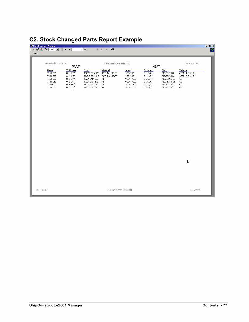
Stock Changed Parts Report This report will show information about any parts that have been nested on a plate and have then subsequently had their stock information changed. These parts are now essentially incorrectly nested and should be addressed. (See Appendix C2)

58 •••• Generating Reports ShipConstructor2001 Manager

ShipConstructor2001 Manager Contents •••• 59
Common Tasks
Upgrading a ShipConstructor2000 Project To upgrade a ShipConstructor2000 project so that it may be used with ShipConstructor2001 is a relatively simple task. See the appropriate sections in this manual for more information on the individual operations required.
Step 1 - Create a New Database The first step in the process is to create a SQL Server project database. To accomplish this task, open Manager and connect to any existing project. From the Database Manager, select the Copy function. The new database we are creating will exist on the same server as the project you select as the source for the copy. Enter the name of the project you would like to upgrade as the name for the new database. The copy will be created.
Step 2 - Import the Data Once the copy is created, open Manager (or simply change the current connection if you are still in Manager) and connect to the new database using the third connection option outlined in the Opening a Project section of this manual. Under Database Utilities select the Import Data option. Using the Access import option, select the original project MDB. Ensure that you are truly connected to the new database you created and then begin the import.
Step 3 - Create the Project File At this point it would be a good idea to create a copy of the entire folder that contains the project. You will be using the current project folder for the 2001 project and it may be in your best interest to have a completely intact 2000 project. The last step in the process is to create the Project File for the project. We will use an existing project file as a template. Copy the .PRO file from an existing project into the folder containing the project you are updating. The .PRO file should always be placed directly in the root of the project folder. Rename the .PRO file with the name of the project you are updating. (e.g. <YourProjectName>.pro). After renaming the .pro file open it with a text editor such as Notepad. The contents of the file will look similar to the first image below. Change the “Database” entry to the name of the new project. Ensure that the “Server” entry contains the name of the server the new project database was created on. If the .PRO file was copied from another of your own 2001 projects it may contain the correct ‘Server’ entry already. The second image below contains a .Pro file that has been changed appropriately.

60 •••• Common Tasks ShipConstructor2001 Manager
Transferring a Project to Another Server This procedure is necessary if you need to send or receive a ShipConstructor project with someone.
On the Server to Copy Project From:
Step 1 – Backup the Database To accomplish this task, open Manager and connect to any existing project. From the Database Manager, select the project database to backup then click the Backup button. The database backup file is located at:
“C:\Program Files\Microsoft SQL Server\MSSQL\Backup”. The backup file will be named in the following manner:
<YOUR PROJECT NAME> + <Current Date/Time> + .bak
Step 2 – Package the project Package the database backup file along with the project folder.
On the Server to Place the Project:
Step 3 – Copy the Project to the Project Folder Place the packaged project files to the new location.
Step 4 - Create a New Database Create a SQL Server project database for the project only if one does not exist already. To accomplish this task, open Manager and connect to any existing project. From the Database Manager, select the Copy function. Enter the name of the project (same name as the PRO file or the project folder). The copy will be created.
Step 5 - Import the Data Restore the data from the database backup file. Under Database Manager, select the Restore function. Select the database backup file that was created in step 1.
On a client computer:
Step 6 – Register to the Project in ShipConstructor On a client computer start ShipConstructor and register to the new project. When registering, ShipConstructor will attempt to connect to the server listed in the PRO file. On the first try ShipConstructor will timeout and show a similar message as shown below.
Click OK. Then select the server and database that you just created in step 4.

ShipConstructor2001 Manager Contents •••• 61
Note: Make sure that the project PRO file is not a read only file or else the new connection information cannot be saved.
Exporting a Report
Overview The button that is available when you are previewing a report in Manager allows you to export the current report to other formats.
You may select from several formats for the export in the first dropdown list. The second list sets the destination type for the export. The “Disk file” selection will be sufficient for most of your exporting needs. The options that you will see in the next dialog for the export depend on the format you have selected for the import. Experience will tell you what the best options are for each format. The best export option for display purposes is the PDF format.
Exporting to Excel, Word or Similar Applications When exporting to a format that is not a simple graphical format used for display purposes, such as Excel or Word, it may be necessary to export to an intermediate format first. Without this intermediate step, some of the calculated fields in the report may appear as blank fields in the final export. Often the best intermediate format is the “HTML 3.2” (not “DHTML 4.0”) selection in the Format dropdown list. When you select the “HTML 3.2” option and then click OK you will be prompted for a number of setting s for the export.

62 •••• Common Tasks ShipConstructor2001 Manager
The settings shown in the dialog are the best options for generating a single HTML document that can then be opened with the intended application. Once the export is complete, open Excel or Word and then open the HTML file. Alternatively you can right-click on the HTML file and select the “Open With…” option from the context sensitive menu that appears and then select the intended application. Once you have opened the HTML file with the target application, save it in the application’s standard format.

ShipConstructor2001 Manager Contents •••• 63
Appendix
A. PWBS Example Reports
A1. Build Strategy
Summary

64 •••• Appendix ShipConstructor2001 Manager
Detailed
ShipConstructor2001 Manager Contents •••• 65
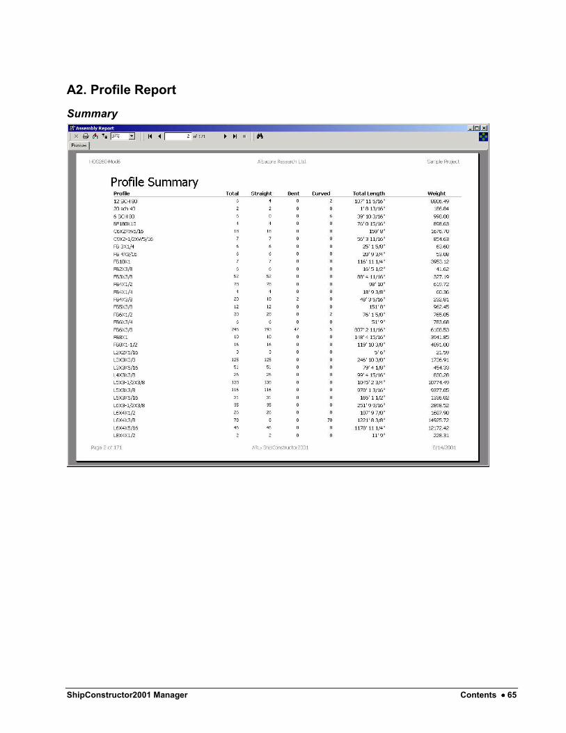
A2. Profile Report
Summary

66 •••• Appendix ShipConstructor2001 Manager
Detailed

ShipConstructor2001 Manager Contents •••• 67
A3. Standard Part Report
Summary

68 •••• Appendix ShipConstructor2001 Manager
Detailed
ShipConstructor2001 Manager Contents •••• 69
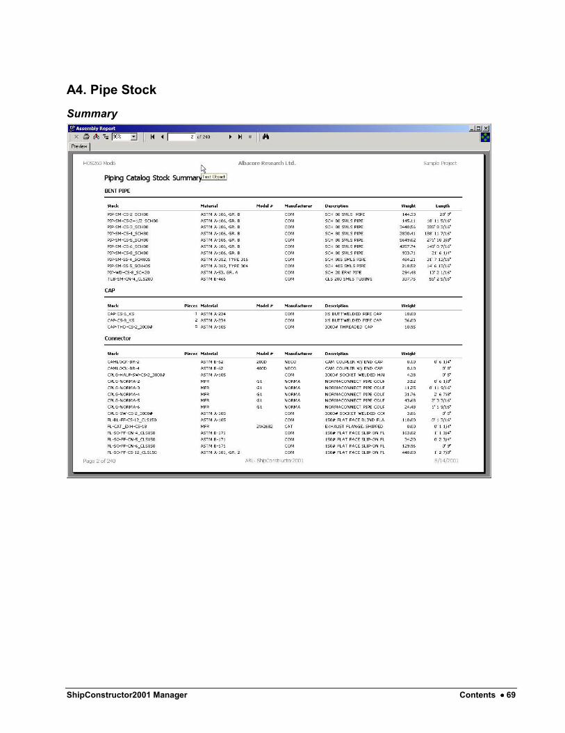
A4. Pipe Stock
Summary
70 •••• Appendix ShipConstructor2001 Manager
Detailed

ShipConstructor2001 Manager Contents •••• 71
A5. Pipe Penetration

72 •••• Appendix ShipConstructor2001 Manager
B. SWBS Example Reports
B1. Pipe Stock
Summary

ShipConstructor2001 Manager Contents •••• 73
Detailed

74 •••• Appendix ShipConstructor2001 Manager
B2. Pipe Penetration

ShipConstructor2001 Manager Contents •••• 75
C. Nesting Example Reports
C1. Standard Nest Report
Summary

76 •••• Appendix ShipConstructor2001 Manager
Detailed
ShipConstructor2001 Manager Contents •••• 77
C2. Stock Changed Parts Report Example

ShipConstructor2001 Manager Contents •••• 79
Index
A assembly drawing 41, 46 assigned 14, 37, 39–40, 46, 49–54
B Backup 17–21 Bill of Materials 41–42, 45 BOM 41–43, 45–46 BOM Display 45 Build Strategy 49, 52, 63
C Change Password 7 Colors 10, 14–16 Compare 23 configuration 6 Copy 18, 59, 60 Crystal Reports 47
D database utilities 17–24 DBMS 1 Delete 5, 18, 26–27, 29–30, 34–38, 40
E Endcuts 29–30 Endcuts Library 29–30 Excel 61–62 Export 48, 61–62
F Flange 13, 31 Flange Library 33–34
G Group Tree 48
H HTML 48, 61–62
I Import 20–21, 59–61, 59–61
L Linetype Scale 13
M Marking 10–13 Materials 35, 41–42, 45 Materials Library 35 Misc 15 MS Access 1, 20
N naming convention 11 NC Machines 39–40 NC Machines Library 39–40 Nesting 14, 47, 56–57 No Processing 13
O Outfit Types 27
P Paints 37–38 Paints Library 37 Parts 10–14, 26, 29–30, 36–38, 43–44, 47, 49–50, 52,
55, 57, 77 permissions 6 piecemarks 11 Pipe Colors 16 Pipe Penetration 52, 54, 71, 74 Pipe Stock 52, 54, 69, 72 Plate Sizes 26 Profile 29, 31, 48, 52, 65 Project File 3, 59 PWBS 12, 41, 46–47, 49–53, 55, 63 PWBS and SWBS 47, 49, 53, 55 PWBS assembly 47, 50, 52
R Recent ShipConstructor Projects 3

80 •••• Index ShipConstructor2001 Manager
reporting 1, 47 Reports 9, 15, 47–48, 52, 54, 56–57, 63, 72, 75 Restore 19–22
S Seagate Software 47 Select a ShipConstructor Database 4 Select a ShipConstructor Project 3 ShipConstructor2000 20, 59 ShipConstructor2001 1, 3, 5, 59 Shorten Fold 13 SQL Server 1, 4, 19, 21, 59, 60 Standard Part 43, 52, 67 Standard Parts 43–44, 52 Standard Quantities 43 Stocks 24–26, 35–36, 39, 52, 54 Stocks Library 24–26 Sub-Assembly 43 sub-report 48 SWBS 47, 49, 53–55, 72 Symbols 12–14
T template 41, 46, 59 TreeView 48
U Units 9, 12–13, 47, 57 Update 4, 21, 48 upgrade 59 user 1, 5–7, 48 users 1, 5–7, 19–23, 49, 52–53
W Word 61–62