shipbuilding and repair quality standard for hull structures - ABS
44
GUIDE FOR SHIPBUILDING AND REPAIR QUALITY STANDARD FOR HULL STRUCTURES DURING CONSTRUCTION MARCH 2007 American Bureau of Shipping Incorporated by Act of Legislature of the State of New York 1862 Copyright © 2007 American Bureau of Shipping ABS Plaza 16855 Northchase Drive Houston, TX 77060 USA
Transcript of shipbuilding and repair quality standard for hull structures - ABS

GUIDE FOR
SHIPBUILDING AND REPAIR QUALITY STANDARD FOR HULL STRUCTURES DURING CONSTRUCTION
MARCH 2007
American Bureau of Shipping Incorporated by Act of Legislature of the State of New York 1862
Copyright © 2007 American Bureau of Shipping ABS Plaza 16855 Northchase Drive Houston, TX 77060 USA

This Page Intentionally Left Blank

ABS GUIDE FOR SHIPBUILDING AND REPAIR QUALITY STANDARD FOR HULL STRUCTURES DURING CONSTRUCTION . 2007 iii
Foreword
This Guide contains information obtained from IACS Recommendation No. 47 “Shipbuilding and Repair Quality Standard”. In order to be consistent with ABS requirements, some specific standards have been modified from the original. The modified standards are indicated in the “Remarks” column of the tables, along with the Rule reference.
This second edition of the Guide, developed based on IACS Recommendation No. 47 (Rev. 3, Nov. 2006), supersedes the first edition published in July 1998.

This Page Intentionally Left Blank

ABS GUIDE FOR SHIPBUILDING AND REPAIR QUALITY STANDARD FOR HULL STRUCTURES DURING CONSTRUCTION . 2007 v
GUIDE FOR
SHIPBUILDING AND REPAIR QUALITY STANDARD FOR HULL STRUCTURES DURING CONSTRUCTION
CONTENTS 1 Applicability............................................................................1 2 Scope ......................................................................................1 3 General Requirements...........................................................2 4 Qualification of Personnel and Procedures ........................2
4.1 Qualification of Welders.........................................................2 4.2 Qualification of Welding Procedures......................................2 4.3 Qualifications of NDE Operators............................................2
5 Materials..................................................................................2 5.1 Materials for Structural Members...........................................2 5.2 Details, Standards and Tolerance Limits ...............................2 TABLE 1 Flanged Longitudinals and Flanged Brackets..............4 TABLE 2 Built-up Sections ..........................................................5 TABLE 3 Corrugated Bulkheads .................................................6 TABLE 4 Pillars, Brackets and Stiffeners....................................7 TABLE 5 Maximum Heating Temperature on Surface for Line
Heating.........................................................................8 TABLE 6 Block Assembly............................................................9 TABLE 7 Special Sub-Assembly ...............................................10 TABLE 8 Shape.........................................................................11 TABLE 9 Shape.........................................................................12 TABLE 10 Fairness of Plating Between Frames.........................13 TABLE 11 Fairness of Plating with Frames.................................14 TABLE 12 Alignment ...................................................................15 TABLE 13 Alignment ...................................................................16 TABLE 14 Alignment ...................................................................17 TABLE 15 Typical Butt Plate Edge Preparation
(Manual Welding).......................................................18 TABLE 16 Typical Butt Plate Edge Preparation
(Manual Welding).......................................................19

vi ABS GUIDE FOR SHIPBUILDING AND REPAIR QUALITY STANDARD FOR HULL STRUCTURES DURING CONSTRUCTION . 2007
TABLE 17 Typical Fillet Weld Plate Edge Preparation (Manual Welding).......................................................20
TABLE 18 Typical Fillet Weld Plate Edge Preparation (Manual Welding).......................................................21
TABLE 19 Typical Butt and Fillet Weld Profile (Manual Welding).......................................................22
TABLE 20 Distance Between Welds ...........................................23 TABLE 21 Automatic Welding .....................................................24 TABLE 22 Typical Misalignment Repair......................................25 TABLE 23 Typical Misalignment Repair......................................26 TABLE 24 Typical Misalignment Repair......................................27 TABLE 25 Typical Butt Weld Plate Edge Preparation Repair
(Manual Welding).......................................................28 TABLE 26 Typical Butt Weld Plate Edge Preparation Repair
(Manual Welding).......................................................29 TABLE 27 Typical Fillet Weld Plate Edge Preparation Repair
(Manual Welding).......................................................30 TABLE 28 Typical Fillet Weld Plate Edge Preparation Repair
(Manual Welding).......................................................31 TABLE 29 Typical Fillet Weld Plate Edge Preparation Repair
(Manual Welding).......................................................32 TABLE 30 Typical Fillet and Butt Weld Plate Edge Preparation
Repair (Manual Welding) ...........................................33 TABLE 31 Distance Between Welds Repair ...............................34 TABLE 32 Erroneous Hole Repair ..............................................35 TABLE 33 Repair by Insert Plate ................................................36 TABLE 34 Weld Surface Repair ..................................................37

ABS GUIDE FOR SHIPBUILDING AND REPAIR QUALITY STANDARD FOR HULL STRUCTURES DURING CONSTRUCTION . 2007 1
1 Applicability
This Guide provides guidance on shipbuilding quality standards for the hull structure during construction.
Whereas the standard generally applies to:
• Conventional ship types • Hull structures constructed from normal and higher strength hull structural steel, the applicability
of the standard is in each case to be agreed upon by the Bureau
The standard generally does not apply to the new construction of:
• Special types of ships as, e.g., gas tankers
• Structures fabricated from stainless steel or other, special types or grades of steel Details relevant to structures or fabrication procedures not covered by this standard are to be approved on a case-by-case basis of procedure qualifications and/or recognized national standards.
2 Scope
The standard covers typical construction methods and gives guidance on quality standards for the most important aspects of such construction. Unless explicitly stated elsewhere in the standard, the level of workmanship reflected herein will in principle be acceptable for primary and secondary structure of conventional designs. A more stringent standard may however be required for critical and highly stressed areas of the hull, and this is to be agreed with the Bureau in each case.
It is intended that these standards provide guidance where established shipbuilding or national standards accepted by the Bureau do not exist.
For use of this standard, fabrication fit-ups, deflections and similar quality attributes are intended to be uniformly distributed about the nominal values. The shipyard is to take corrective action to improve work processes that produce measurements where a skewed distribution is evident. Relying upon remedial steps that truncate a skewed distribution of the quality attribute is unacceptable.
In this standard, both a “Standard” range and a “Limit” range are listed. The “Standard” range represents the target range expected to be met in regular work under normal circumstances. The “Limit” range represents the maximum allowable deviation from the “Standard” range. Work beyond the “Standard” range but within the “Limit” range is acceptable.

2 ABS GUIDE FOR SHIPBUILDING AND REPAIR QUALITY STANDARD FOR HULL STRUCTURES DURING CONSTRUCTION . 2007
3 General Requirements
In general, the work is to be carried out in accordance with the Rules and to the satisfaction of attending Surveyor.
Provisions are to be made for proper accessibility, staging, lighting and ventilation. Welding operations are to be carried out under shelter from rain, snow and wind.
Welding of hull structures is to be carried out by qualified welders, according to approved and qualified welding procedures and with welding consumables approved by the Bureau. Welding operations are to be carried out under proper supervision by the shipbuilder.
4 Qualification of Personnel and Procedures
4.1 Qualification of Welders Welders are to be qualified in accordance with 2-4-3/11 of the ABS Rules for Materials and Welding (Part 2). Subcontractors are to keep records of welders’ qualification and, when required, furnish valid approval test certificates.
Welding operators using fully mechanized or fully automatic processes generally need not pass approval testing provided that the production welds made by the operators are of the required quality. However, operators are to receive adequate training in setting or programming and operating the equipment. Records of training and production test results shall be maintained on individual operator’s files and records, and be made available to the Bureau for inspection when requested.
4.2 Qualification of Welding Procedures Welding procedures are to be qualified in accordance with 2-4-1/1.7 of the ABS Rules for Materials and Welding (Part 2). The welding procedure should be supported by a welding procedure qualification record. The specification is to include the welding process, types of electrodes, weld shape, edge preparation, welding techniques and positions.
4.3 Qualifications of NDE Operators Personnel performing nondestructive examination for the purpose of assessing quality of welds in connection with new construction covered by this Guide are to be qualified in accordance with the applicable Bureau’s requirements or to a recognized national or international qualification scheme. Records of operators and their current certificates are to be kept and made available to the Surveyor for inspection.
5 Materials
5.1 Materials for Structural Members All materials, including weld consumables, to be used for the structural members are to be in accordance with Bureau approved construction plans and with the ABS Rules for Materials and Welding (Part 2).
5.2 Details, Standards and Tolerance Limits Details, standards and tolerance limits may be found in the following Tables:

ABS GUIDE FOR SHIPBUILDING AND REPAIR QUALITY STANDARD FOR HULL STRUCTURES DURING CONSTRUCTION . 2007 3
Detail Table # Fabrication and Fairness • Flanged Longitudinals and Flanged Brackets • Built-Up Sections • Corrugated Bulkheads • Pillars, Brackets And Stiffeners • Maximum Heating Temperature On Surface For Line Heating • Block Assembly • Special sub-assembly • Shape • Fairness of Plating Between Frames • Fairness of Plating with Frames
• 1 • 2 • 3 • 4 • 5 • 6 • 7 • 8 and 9 • 10 • 11
Alignment • Quality Standards of Hull Structural Components During New
Construction
• 12, 13 and 14
• The Bureau may require a closer construction
tolerance in areas requiring special attention, as follows: - Regions exposed to high stress
concentrations - Fatigue prone area - Detail design block erection joints - Higher tensile steel regions
Welding Details • Typical Butt Plate Edge Preparation (Manual Welding) • Typical Fillet Weld Plate Edge Preparation (Manual Welding) • Typical Butt and Fillet Weld Profile (Manual Welding) • Distance Between Welds • Automatic Welding
• 15 and 16 • 17 and 18 • 19 • 20 • 21
Repair • Typical Misalignment Repair • Typical Butt Weld Plate Edge Preparation Repair (Manual Welding) • Typical Fillet Weld Edge Preparation Repair (Manual Welding) • Typical Fillet and Butt Weld Profile Repair (Manual Welding) • Distance Between Welds Repair • Erroneous Hole Repair • Repair By Insert Plate • Weld Surface Repair
• 22 to 24 • 25 and 26 • 27 to 29 • 30 • 31 • 32 • 33 • 34

4 ABS GUIDE FOR SHIPBUILDING AND REPAIR QUALITY STANDARD FOR HULL STRUCTURES DURING CONSTRUCTION . 2007
TABLE 1 Flanged Longitudinals and Flanged Brackets
Detail Standard Limit Remarks Breadth of flange
a
b
Compared to correct size
± 3 mm ± 5 mm
Angle between flange and web
a
Compared to template
± 3 mm ± 5 mm per 100 mm of a
Straightness in plane of flange and web
± 10 mm ± 25 mm per 10 m

ABS GUIDE FOR SHIPBUILDING AND REPAIR QUALITY STANDARD FOR HULL STRUCTURES DURING CONSTRUCTION . 2007 5
TABLE 2 Built-up Sections
Detail Standard Limit Remarks Frames and longitudinal
a
± 1.5 mm ± 3 mm per 100 mm of a
Distortion of face plate
a
d
d ≤ 3 + a/100 mm d ≤ 5 + a/100 mm
Distortion of built-up longitudinal, girder, and transverse at upper edge and flange
± 10 mm ± 25 mm per 10 m in length

6 ABS GUIDE FOR SHIPBUILDING AND REPAIR QUALITY STANDARD FOR HULL STRUCTURES DURING CONSTRUCTION . 2007
TABLE 3 Corrugated Bulkheads
Detail Standard Limit Remarks Mechanical bending
t
R
R ≥ 3t mm 2t Material to be suitable for cold flanging (forming) and welding in way of radius
Depth of corrugation
± 3 mm ± 6 mm
Breadth of corrugation
± 3 mm ± 6 mm
Pitch and depth of swedged corrugated bulkhead compared with correct value
h
P P
h: ± 2.5 mm Where it is not aligned with other bulkheads
P: ± 6 mm Where it is aligned with
other bulkheads P: ± 2 mm
h: ± 5 mm Where it is not aligned with other bulkheads
P: ± 9 mm Where it is aligned with
other bulkheads P: ± 3 mm

ABS GUIDE FOR SHIPBUILDING AND REPAIR QUALITY STANDARD FOR HULL STRUCTURES DURING CONSTRUCTION . 2007 7
TABLE 4 Pillars, Brackets and Stiffeners
Detail Standard Limit Remarks Pillar (between decks)
4 mm 6 mm
Cylindrical structure diameter (pillars, masts, posts, etc.)
D
± D/200 mm max. + 5 mm
± D/150 mm max. 7.5 mm
Tripping bracket and small stiffener, distortion at the part of free edge
at
a ≤ t/2 mm t
Snipe end of secondary face plates and stiffeners
See 3-1-2/15.3 of the ABS Rules for Building and Classing Steel Vessels

8 ABS GUIDE FOR SHIPBUILDING AND REPAIR QUALITY STANDARD FOR HULL STRUCTURES DURING CONSTRUCTION . 2007
TABLE 5 Maximum Heating Temperature on Surface for Line Heating
Item Standard Limit Remarks Water cooling just after heating
Under 650°C
Air cooling after heating
Under 900°C
Conventional Process AH32-EH32 & AH36-EH36 TCMP type AH32-EH32 & AH36-EH36 (Ceq. > 0.38%)
Air cooling and subsequent water cooling after heating
Under 900°C (starting temperature of water cooling to be under 500°C)
TMCP type AH32-DH32 & AH36-DH36 (Ceq. ≤ 0.38%)
Water cooling just after heating or air cooling
Under 1000°C
TMCP type EH32 & EH36 (Ceq. ≤ 0.38%)
Water cooling just after heating or air cooling
Under 900°C
Note:
( )%15
CuNi5
VMoCr6
MnCCeq ++++++=

ABS GUIDE FOR SHIPBUILDING AND REPAIR QUALITY STANDARD FOR HULL STRUCTURES DURING CONSTRUCTION . 2007 9
TABLE 6 Block Assembly
Item Standard Limit Remarks Flat Plate Assembly Length and Breadth Distortion Squareness Deviation of interior members from plate
± 2.5 mm ± 10 mm ± 5 mm 5 mm
± 5 mm ± 20 mm ± 10 mm 10 mm
Curved Plate Assembly Length and Breadth Distortion Squareness Deviation of interior members from plate
± 2.5 mm ± 10 mm ± 10 mm
5 mm
± 5 mm ± 20 mm ± 15 mm 10 mm
Measured along the girth
Flat Cubic Assembly Length and Breadth Distortion Squareness Deviation of interior members from plate Twist Deviation between upper and lower plate
± 2.5 mm ± 10 mm ± 10 mm
5 mm
± 10 mm ± 5 mm
± 5 mm ± 20 mm ± 10 mm 10 mm
± 20 mm ± 10 mm
Curved cubic assembly Length and Breadth Distortion Squareness Deviation of interior members from plate Twist Deviation between upper and lower plate
2.5 mm ± 10 mm ± 10 mm
5 mm
± 15 mm ± 7 mm
± 5 mm ± 20 mm ± 15 mm 10 mm
± 25 mm ± 15 mm
Measured along the girth

10 ABS GUIDE FOR SHIPBUILDING AND REPAIR QUALITY STANDARD FOR HULL STRUCTURES DURING CONSTRUCTION . 2007
TABLE 7 Special Sub-Assembly
Item Standard Limit Remarks Distance between upper and lower gudgeon
± 5 mm ± 10 mm
Distance between aft edge of boss and aft peak bulkhead
± 5 mm ± 10 mm
Twist of sub-assembly of stern frame
5 mm 10 mm
Deviation of rudder from shaft center line
4 mm 8 mm
Twist of rudder plate
6 mm 10 mm
Flatness of top plate of main engine bed
5 mm 10 mm
Breadth and length of top plate of main engine bed
± 4 mm ± 6 mm

ABS GUIDE FOR SHIPBUILDING AND REPAIR QUALITY STANDARD FOR HULL STRUCTURES DURING CONSTRUCTION . 2007 11
TABLE 8 Shape
Detail Standard Limit Remarks Deformation for the whole length
± 50 mm per 100 m against the line of keel sighting
Deformation for the distance between two adjacent bulkheads
± 15 mm
Cocking -up of fore body
± 30 mm
Cocking-up of aft-body
± 20 mm
Rise of floor amidships
CL
± 15 mm

12 ABS GUIDE FOR SHIPBUILDING AND REPAIR QUALITY STANDARD FOR HULL STRUCTURES DURING CONSTRUCTION . 2007
TABLE 9 Shape
Item Standard Limit Remarks Length between perpendiculars
± 50 per 100 m Applied to ships of 100 m length and above. For the convenience of the measurement the point where the keel is connected to the curve of the stern may be substituted for the fore perpendicular in the measurement of the length.
Length between aft edge of boss and main engine
± 25 mm
Molded breadth at midship
± 15 mm Applied to ships of 15 m breadth and above. Measured on the upper deck
Molded depth at midship
± 10 mm Applied to ships of 10 meter depth and above

ABS GUIDE FOR SHIPBUILDING AND REPAIR QUALITY STANDARD FOR HULL STRUCTURES DURING CONSTRUCTION . 2007 13
TABLE 10 Fairness of Plating Between Frames
Item Standard Limit Remarks Shell plate Parallel part
(side & bottom shell)
4 mm
Fore and aft part
5 mm
Tank Top plate
4 mm
Bulkhead Longitudinal bulkhead Transverse bulkhead Swash bulkhead
6 mm 6 mm 6 mm
8 mm
s
Strength deck Parallel part
4 mm
Fore and aft part
6 mm 9 mm
Covered part
7 mm 9 mm
Second deck Bare part
6 mm 8 mm
Covered part
7 mm 9 mm
Forecastle deck poop deck
Bare part 4 mm 8 mm
Covered deck
6 mm 9 mm
Superstructure deck
Bare part
4 mm 6 mm
Covered part
7 mm 9 mm
House wall Outside wall
4 mm 6 mm
Inside wall
6 mm 8 mm
Covered part
7 mm 9 mm
Interior member (web of girder, etc)
5 mm 7 mm
Floor and girder in double bottom
5 mm 7 mm

14 ABS GUIDE FOR SHIPBUILDING AND REPAIR QUALITY STANDARD FOR HULL STRUCTURES DURING CONSTRUCTION . 2007
TABLE 11 Fairness of Plating with Frames
Item Standard Limit Remarks Shell Plate
Parallel part ± 2l/1000 mm ± 3l/1000 mm
Fore and aft part
± 3l/1000 mm ± 4l/1000 mm
Strength deck (excluding cross deck) and top plate of double bottom
± l/1000 mm ± 4l/1000 mm
Bulkhead
± 4l/1000 mm ± 5l/1000 mm
Others
± 5l/1000 mm ± 6l/1000 mm
l = span of frame To be measured between one trans. space (min. l = 3 m)
l m l = span of frame
(minimum l =3 m)
To be measured between one transverse space

ABS GUIDE FOR SHIPBUILDING AND REPAIR QUALITY STANDARD FOR HULL STRUCTURES DURING CONSTRUCTION . 2007 15
TABLE 12 Alignment
Detail Standard Limit Remarks Alignment of butt welds
a
t
a
t
a ≤ 0.15t strength a ≤ 0.2t other
a ≤ 3.0 mm
Alignment of fillet welds
a
a1t1
t3
t2
Strength and higher tensile:
a ≤ t1/4 measured on the median or a1 ≤ (3t1 – 2t2)/4 measured on the heel line
Other:
a ≤ t1/3 measured on the median or a1 ≤ (5t1 – 3t2)/6 measured on the heel line
Strength and higher tensile:
a ≤ t1/3 measured on the median or a1 ≤ t1/3 measured on the heel line
Other:
a ≤ t1/2 measured on the median or a1 ≤ t1/2 measured on the heel line
Where t3 is less than t1 then t3 should be substituted for t1 in the standard
Alignment of fillet welds
a
a1
t1
t3
t2
θ°
Strength and higher tensile:
a ≤ t1/4 measured on the median or a1 ≤ (3t1 – 2t2)/4 measured on the heel line
Other:
a ≤ t1/3 measured on the median or a1 ≤ (5t1 – 3t2)/6 measured on the heel line
Strength and higher tensile:
a ≤ t1/3 measured on the median or a1 ≤ t1/3 measured on the heel line
Other:
a ≤ t1/2 measured on the median or a1 ≤ t1/2 measured on the heel line
Where t3 is less than t1 then t3 should be substituted for t1 in the standard

16 ABS GUIDE FOR SHIPBUILDING AND REPAIR QUALITY STANDARD FOR HULL STRUCTURES DURING CONSTRUCTION . 2007
TABLE 13 Alignment
Detail Standard Limit Remarks Alignment of flange of T-longitudinal
a b
a ≤ 0.04b strength a = 8.0 mm
Alignment of height of T-bar, L-angle bar or bulb
a t
Primary members a ≤ 0.15t
Secondary members
a ≤ 0.20t
a = 3.0 mm
Alignment of panel stiffener
L
d
d ≤ L/50
Gap between bracket/intercostal and stiffener
a
a ≤ 2.0 mm a = 3 mm
Alignment of lap welds
a
a
a ≤ 2.0 mm a = 3 mm

ABS GUIDE FOR SHIPBUILDING AND REPAIR QUALITY STANDARD FOR HULL STRUCTURES DURING CONSTRUCTION . 2007 17
TABLE 14 Alignment
Detail Standard Limit Remarks Gap between beam and frame
a
a ≤ 2.0 mm a = 5.0 mm
Gap around stiffener cut-out
s ss
s ≤ 2.0 mm s = 3.0 mm
18 ABS GUIDE FOR SHIPBUILDING AND REPAIR QUALITY STANDARD FOR HULL STRUCTURES DURING CONSTRUCTION . 2007
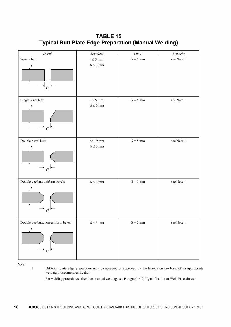
TABLE 15 Typical Butt Plate Edge Preparation (Manual Welding)
Detail Standard Limit Remarks Square butt
t
G
t ≤ 5 mm G ≤ 3 mm
G = 5 mm see Note 1
Single level butt
t
G
t > 5 mm G ≤ 3 mm
G = 5 mm see Note 1
Double bevel butt
t
G
t > 19 mm G ≤ 3 mm
G = 5 mm see Note 1
Double vee butt uniform bevels
t
G
G ≤ 3 mm G = 5 mm see Note 1
Double vee butt, non-uniform bevel
t
G
G ≤ 3 mm G = 5 mm see Note 1
Note: 1 Different plate edge preparation may be accepted or approved by the Bureau on the basis of an appropriate
welding procedure specification.
For welding procedures other than manual welding, see Paragraph 4.2, “Qualification of Weld Procedures”.

ABS GUIDE FOR SHIPBUILDING AND REPAIR QUALITY STANDARD FOR HULL STRUCTURES DURING CONSTRUCTION . 2007 19
TABLE 16 Typical Butt Plate Edge Preparation (Manual Welding)
Detail Standard Limit Remarks Single vee butt, one side welding with backing strip (temporary or permanent)
t
G
G = 3 - 9 mm G = 16 mm see Note 1
Single vee butt
t
G
G ≤ 3 mm G = 5 mm see Note 1
Note: 1 Different plate edge preparation may be accepted or approved by the Bureau on the basis of an appropriate
welding procedure specification. For welding procedures other than manual welding, see Paragraph 4.2, “Qualification of Weld Procedures”.

20 ABS GUIDE FOR SHIPBUILDING AND REPAIR QUALITY STANDARD FOR HULL STRUCTURES DURING CONSTRUCTION . 2007
TABLE 17 Typical Fillet Weld Plate Edge Preparation (Manual Welding)
Detail Standard Limit Remarks Tee Fillet
t
G
G ≤ 2 mm G = 3 mm see Note 1
Small angle fillet
G
G ≤ 2 mm G = 3 mm see Note 1
Single bevel tee with permanent backing
t
Gθ°
G ≤ 4 - 6 mm θ° = 30° - 45°
G = 16 mm Not normally for strength members
also see Note 1
Single bevel tee
t
G
G ≤ 3 mm see Note 1
Note: 1 Different plate edge preparation may be accepted or approved by the Bureau on the basis of an appropriate
welding procedure specification.
For welding procedures other than manual welding, see Paragraph 4.2, “Qualification of Weld Procedures”.

ABS GUIDE FOR SHIPBUILDING AND REPAIR QUALITY STANDARD FOR HULL STRUCTURES DURING CONSTRUCTION . 2007 21
TABLE 18 Typical Fillet Weld Plate Edge Preparation (Manual Welding)
Detail Standard Limit Remarks Single ‘J’ tee
t
G
G =2.5 - 4 mm see Note 1
Double bevel tee symmetrical t
G
t > 19 mm G ≤ 3 mm
see Note 1
Double bevel tee asymmetrical
t
G
t > 19 mm G ≤ 3 mm
see Note 1
Double J bevel symmetrical
t
G
G =2.5 - 4 mm see Note 1
Note: 1 Different plate edge preparation may be accepted or approved by the Bureau on the basis of an appropriate
welding procedure specification.
For welding procedures other than manual welding, see Paragraph 4.2, “Qualification of Weld Procedures”.

22 ABS GUIDE FOR SHIPBUILDING AND REPAIR QUALITY STANDARD FOR HULL STRUCTURES DURING CONSTRUCTION . 2007
TABLE 19 Typical Butt and Fillet Weld Profile (Manual Welding)
Detail Standard Limit Remarks Butt weld toe angle
t θ° h
θ ≤ 60° h ≤ 6 mm
θ ≤ 90°
Butt weld undercut
D
D = 0.5 mm
Fillet weld leg length
a45°
s
s = leg length a = throat depth
s ≥ 0.9sd a ≥ 0.9ad
over short weld lengths
sd = design s ad = design a
Fillet weld toe angle
θ°
θ ≤ 90° In areas of stress concentration and fatigue, the Bureau may require a lesser angle
Fillet weld undercut
D
D = 0.5 mm

ABS GUIDE FOR SHIPBUILDING AND REPAIR QUALITY STANDARD FOR HULL STRUCTURES DURING CONSTRUCTION . 2007 23
TABLE 20 Distance Between Welds
Detail Standard Limit Remarks Scallops over weld seams
d
For significant members d ≥ 5 mm
For other members
d ≥ 0 mm
The “d” is to be measured from the toe of the fillet weld to the toe of the butt weld.
Distance between two butt welds
d
d ≥ 0 mm
Distance between butt weld and fillet weld
d
For significant members d ≥ 10 mm
For other members
d ≥ 0 mm
Distance between butt welds
d
d
For cut-outs d ≥ 30 mm
For margin plates
d ≥ 300 mm
150 mm

24 ABS GUIDE FOR SHIPBUILDING AND REPAIR QUALITY STANDARD FOR HULL STRUCTURES DURING CONSTRUCTION . 2007
TABLE 21 Automatic Welding
Detail Standard Limit Remarks Submerged Arc Welding (SAW)
G
G
G
0 ≤ G ≤ 0.8 mm G = 2 mm Edge preparation as per Tables 15 and 16
SAW may follow WPS approved by the Bureau
See Note 1
Note: 1 Different plate edge preparation may be accepted or approved by the Bureau on the basis of an appropriate
welding procedure specification.
For welding procedures other than manual welding, see Paragraph 4.2, “Qualification of Weld Procedures”.

ABS GUIDE FOR SHIPBUILDING AND REPAIR QUALITY STANDARD FOR HULL STRUCTURES DURING CONSTRUCTION . 2007 25
TABLE 22 Typical Misalignment Repair
Detail Repair Standard Remarks Alignment of butt joints
a
t1
Strength members a > 0.15t1 or a > 3 mm – release and adjust Others a > 0.2t1 or a > 3 mm – release and adjust
t1 is lesser plate thickness
Alignment of fillet welds
a
t1
t3
t2
t1 < t2
Strength and Higher tensile steel t1/3 < a ≤ t1/2 – generally increase weld throat
by 10% a > t1/2 – release and adjust over a minimum
of 50a Other a > t1/2 – release and adjust over a minimum
of 30a
Where t3 is less than t1 then t3 should be substituted for t1 in standard
Alignment of flange of T-longitudinal
a b
L
When 0.04b < a ≤ 0.08b, max 8 mm Grind corners to smooth taper over a minimum distance L = 3a When a > 0.08b or 8 mm Grind corners to smooth taper over a minimum distance L = 50a
Alignment of height of T-bar, L-angle bar or bulb
a
When 3 mm < a ≤ 6 mm Building up by welding When a > 6 mm Release and adjust over minimum L = 50a for primary structure and L = 30a elsewhere
L
Alignment of lap welds
a
a
3 mm < a ≤ 5 mm Weld leg length to be increased by the same amount as increase in gap a > 5 mm Members to be re-aligned
26 ABS GUIDE FOR SHIPBUILDING AND REPAIR QUALITY STANDARD FOR HULL STRUCTURES DURING CONSTRUCTION . 2007
TABLE 23 Typical Misalignment Repair
Detail Repair Standard Remarks Gap between bracket/intercostal and stiffener
a
When 3 mm < a ≤ 5 mm Weld leg length to be increased by increase in gap When 5 mm < a ≤ 10 mm Chamfer 30° - 40° and build up with welding When a > 10 mm Increase gap to 50 mm and fit collar plate
b
t1
t1 ≥ t2
t
b = (2t + 25) mm, min. 50 mm
Gap between beam and frame
a
a > 3 mm – release and adjust

ABS GUIDE FOR SHIPBUILDING AND REPAIR QUALITY STANDARD FOR HULL STRUCTURES DURING CONSTRUCTION . 2007 27
TABLE 24 Typical Misalignment Repair
Detail Repair Standard Remarks Position of scallop
d
When d < 75 mm Web plate to be cut between scallop and slot, and collar plate to be fitted
b (min. 50 mm)
OR fit small collar over scallop
OR fit collar plate over scallop
Gap around stiffener cut-out
s ss
When 3 mm < s ≤ 5 mm Weld leg length to be increased as much as increase in gap opening over 2 mm
When 5 mm < s ≤ 10 mm Nib to be chamfered and built up by welding
When s > 10 mm Cut off nib and fit collar plate with same height as nib
b
20 mm ≤ b ≤ 50 mm

28 ABS GUIDE FOR SHIPBUILDING AND REPAIR QUALITY STANDARD FOR HULL STRUCTURES DURING CONSTRUCTION . 2007
TABLE 25 Typical Butt Weld Plate Edge Preparation Repair (Manual Welding)
Detail Repair Standard Remarks Square butt
t
G
When G ≤ 10 mm Chamfer to 45° and build up by welding When G > 10 mm Build up with backing strip; remove, back gouge and seal weld; or, insert plate, min. width 300 mm
Single bevel butt
t
GR
θ°
Double bevel butt
t
GR
θ°
Double vee butt, uniform bevels
t
GR
θ°
Double vee butt, non-uniform bevel
t
GR
θ°
α°
h
When 5 mm < G ≤ 16 mm Build up gap with welding on one or both sides of preparation, with possible use of backing strip as necessary, to maximum 16 mm. Where a backing strip is used, the backing strip is to be removed, the weld back gouged, and a sealing weld made Different welding procedure by using other backing material approved by the Bureau may be accepted on the basis of an appropriate welding procedure specification.
max. 16 mm
When 16 mm < G ≤ 25 mm Welding up with edge preparation or partly renew welding When G > 25 mm An insert plate of minimum width 300 mm, to be welded in place
300 mm

ABS GUIDE FOR SHIPBUILDING AND REPAIR QUALITY STANDARD FOR HULL STRUCTURES DURING CONSTRUCTION . 2007 29
TABLE 26 Typical Butt Weld Plate Edge Preparation Repair (Manual Welding)
Detail Repair Standard Remarks Single vee butt, one side welding
t
G
θ°
Single vee butt
t
G
θ°
R
When 5 mm < G ≤ 16 mm Build up gap with welding on one or both sides of preparation, with possible use of backing strip as necessary, to maximum 16 mm. Where a backing strip is used, the backing strip is to be removed, the weld back gouged, and a sealing weld made. Different welding procedure by using other backing material approved by the Bureau may be accepted on the basis of an appropriate welding procedure specification.
max. 16 mm
When 16 mm < G ≤ 25 mm Welding up with edge preparation or partly renew welding When G > 25 mm An insert plate of minimum width 300 mm, to be welded in place
300 mm

30 ABS GUIDE FOR SHIPBUILDING AND REPAIR QUALITY STANDARD FOR HULL STRUCTURES DURING CONSTRUCTION . 2007
TABLE 27 Typical Fillet Weld Plate Edge Preparation Repair (Manual Welding)
Detail Repair Standard Remarks
3 mm < G ≤ 5 mm Leg length increased to Rule Leg + (G – 2) 5 mm < G ≤ 16 mm or G ≤ 1.5t Chamfer to 30° to 45°, build up with welding, on one side, with or without backing strip, grind and weld
G
t
30°- 45°
Tee fillet
G
t
G > 16 mm or G > 1.5t New plate to be inserted (min. 300 mm)
300 mmminimum
Liner treatment
G
t2
t
t1
a
b
t2 ≤ t ≤ t1 G ≤ 2 mm a = 5 mm + fillet leg length
Not to be used in cargo area or areas of tensile stress perpendicular to liner

ABS GUIDE FOR SHIPBUILDING AND REPAIR QUALITY STANDARD FOR HULL STRUCTURES DURING CONSTRUCTION . 2007 31
TABLE 28 Typical Fillet Weld Plate Edge Preparation Repair (Manual Welding)
Detail Repair Standard Remarks
3 mm < G ≤ 5 mm Build up weld 5 mm < G ≤ 16 mm Build up with welding, with or without backing strip, remove backing strip if used, back gouge and back weld
G
t
Single bevel tee
G
t
θ°
R
G > 16 mm New plate to be inserted of minimum width 300 mm
300 mmminimum

32 ABS GUIDE FOR SHIPBUILDING AND REPAIR QUALITY STANDARD FOR HULL STRUCTURES DURING CONSTRUCTION . 2007
TABLE 29 Typical Fillet Weld Plate Edge Preparation Repair (Manual Welding)
Detail Repair Standard Remarks Single ‘J’ tee
G
t
θ°R
r
As single bevel tee
Double bevel tee symmetrical
G
R
t
θ°
Double bevel tee asymmetrical
G
R
t
50° 50°
Double J bevel symmetrical
G
R
t
θ°r
When 3 mm < G ≤ 16 mm Build up with welding using ceramic or other approved backing bar, remove, back gouge and back weld
When G > 16 mm Insert plate of minimum height 300 mm to be fitted
300 mmminimum

ABS GUIDE FOR SHIPBUILDING AND REPAIR QUALITY STANDARD FOR HULL STRUCTURES DURING CONSTRUCTION . 2007 33
TABLE 30 Typical Fillet and Butt Weld Plate Edge Preparation Repair
(Manual Welding)
Detail Standard Remarks Fillet weld leg length
a45°
s
Increase leg or throat by welding over
Fillet weld toe angle
θ°
θ > 90° Grinding, and welding, where necessary, to make θ < 90°
Butt weld toe angle
t h
R
θ°
θ > 90° Grinding, and welding, where necessary, to make θ < 90°
Butt weld undercut
D
Fillet weld undercut
D
Where 0.5 < D ≤ 1 mm Undercut to be ground smooth (localized only) Where D > 1 mm Undercut to be filled by welding
Minimum short bead H.T. (Ceq > 0.36%) Length ≥ 50 mm H.T. (Ceq ≤ 0.36%) Length ≥ 30 mm

34 ABS GUIDE FOR SHIPBUILDING AND REPAIR QUALITY STANDARD FOR HULL STRUCTURES DURING CONSTRUCTION . 2007
TABLE 31 Distance Between Welds Repair
Detail Standard Remarks Scallops over weld seams
Hole to be cut and ground smooth to obtain distance

ABS GUIDE FOR SHIPBUILDING AND REPAIR QUALITY STANDARD FOR HULL STRUCTURES DURING CONSTRUCTION . 2007 35
TABLE 32 Erroneous Hole Repair
Detail Standard Remarks Holes made erroneously D < 200 mm
D
Strength members Open hole to minimum 75 mm dia. fit and weld spigot piece
t
t1
DG θ°
l θ = 30° - 40° G = 4 – 6 mm 1/2t < t1 < t
l = 50 mm OR Open hole to over 200 mm and fit insert plate Other members Open hole to over 200 mm and fit insert plate OR fit lap plate
t1
t2
L
t1 = t2 L = 50 mm, min
Fillet weld to be made after butt weld The fitting of spigot pieces in areas of high stress concentration or fatigue is to be approved by the Bureau
Holes made erroneously D ≥ 200 mm
D
Strength members Open hole and fit insert plate Other members Open hole to over 300 mm and fit insert plate OR fit lap plate
t1
t2
L
t1 = t2 L = 50 mm, min

36 ABS GUIDE FOR SHIPBUILDING AND REPAIR QUALITY STANDARD FOR HULL STRUCTURES DURING CONSTRUCTION . 2007
TABLE 33 Repair by Insert Plate
Detail Repair Standard Remarks Repair by insert plate
(1)
(2)
(2)
L
B
(1)
(2)
(2)
L
BR
L = 300 mm minimum B = 300 mm minimum R = 5t mm, 100 mm minimum (1) Seam with insert piece is to be welded first (2) Original seam is to be released and welded
over for a minimum of 100 mm
Repair of built section by insert plate
(1)
Lmin
(2)
(3) (3)
(4)
150150
(3)
(4) (4)
Lmin ≥ 300 mm Welding sequence (1) → (2) → (3) → (4) Web butt weld scallop to be filled during final pass (4)

ABS GUIDE FOR SHIPBUILDING AND REPAIR QUALITY STANDARD FOR HULL STRUCTURES DURING CONSTRUCTION . 2007 37
TABLE 34 Weld Surface Repair
Detail Repair Standard Remarks Weld spatter
1 Remove spatter observed before blasting with scraper or chipping hammer etc.
2 For spatter observed after blasting: a) Remove with a chipping hammer,
scraper, etc. b) For spatter not easily removed with a
chipping hammer, scraper, etc., grind the sharp angle of spatter to make it obtuse
In principal, no grinding is applied to weld surface
Arc Strike
Removed the hardened zone by grinding or other measures such as overlapped weld bead and etc.

This Page Intentionally Left Blank


![ABS Shipbuilding and Repair Standards---Pub87_SRQS_Guide[1]](https://static.fdocuments.us/doc/165x107/577d2a071a28ab4e1ea88523/abs-shipbuilding-and-repair-standards-pub87srqsguide1.jpg)