Ship Structure Committee Project SR-1464 Marine Composites ...
57
Ship Structure Committee Project SR-1464 Marine Composites Non-Destructive Evaluation (NDE) Kick-Off Meeting October 14, 2010 ABS (Washington, DC) Office 1421 Prince Street, Suite 100 Alexandria, VA 22314 Eric Greene 410.263.1348 [email protected] www.EricGreeneAssociates.com
Transcript of Ship Structure Committee Project SR-1464 Marine Composites ...
Ship Structure Committee project SR-1464 Marine Composites Non-Destructive Evaluation (NDE)
Eric Greene Associates, Inc. Kick-Off Meeting
Ship Structure Committee Project SR-1464 Marine Composites Non-Destructive Evaluation (NDE)
Kick-Off Meeting October 14, 2010
ABS (Washington, DC) Office 1421 Prince Street, Suite 100
Alexandria, VA 22314
Eric Greene 410.263.1348 [email protected]
www.EricGreeneAssociates.com
Ship Structure Committee project SR-1464 Marine Composites Non-Destructive Evaluation (NDE)
Eric Greene Associates, Inc. Kick-Off Meeting 1 1
Project Plan
• Literature Search: NDE State-of-the-Art • Define Allowable Defect Size/Characterization • Design Panels with Defects for Evaluation • Build/Procure Test Panels • Damage Test Panels • NDE Test & Video • Correlation of Test Results • Project Documentation (Web Video Content) • Final Report

Ship Structure Committee project SR-1464 Marine Composites Non-Destructive Evaluation (NDE)
Eric Greene Associates, Inc. Kick-Off Meeting 2
Literature Search: NDE State-of-the-Art
• NDE Technology • Previous NDE Studies • Visual Inspection • Ultrasonics • Thermography • Shearography • Modal/Impedance Methods • Structural Health Monitoring

Ship Structure Committee project SR-1464 Marine Composites Non-Destructive Evaluation (NDE)
Eric Greene Associates, Inc. Kick-Off Meeting 3
Cause of Damage
Greg Davis of the nationwide survey firm Davis and Company reported the following damage sources in 1996, as gleaned from their database of over 3000 surveys:
Struck Submerged Object 61%
Collision 17%
Poor Maintenance 14%
Grounding 5%
Manufacturing Problem 3%
Ship Structure Committee project SR-1464 Marine Composites Non-Destructive Evaluation (NDE)
Eric Greene Associates, Inc. Kick-Off Meeting 4
The causes cited above lead to the following types of damage to be assessed:
• Puncture of hull or deck skin(s)
• Delamination (between plies or skin to core bond)
• Fracture or debonding of internal stiffeners, bulkheads and joinery
• Deck joint failure
• Water intrusion into core
• Gel coat stress cracks
Typical Failure Modes
Ship Structure Committee project SR-1464 Marine Composites Non-Destructive Evaluation (NDE)
Eric Greene Associates, Inc. Kick-Off Meeting 5
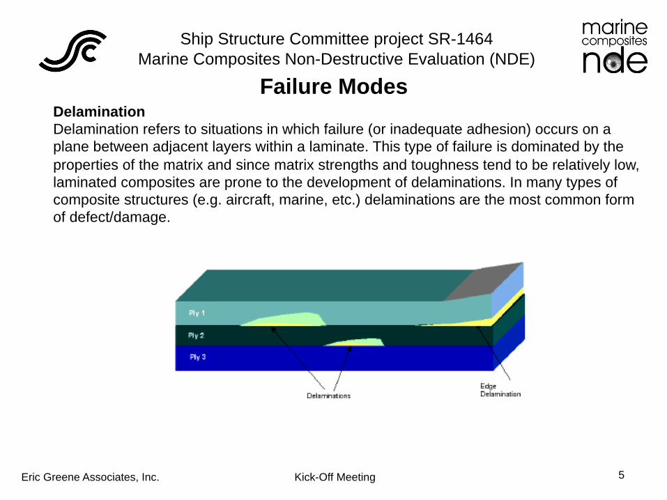
Delamination Delamination refers to situations in which failure (or inadequate adhesion) occurs on a plane between adjacent layers within a laminate. This type of failure is dominated by the properties of the matrix and since matrix strengths and toughness tend to be relatively low, laminated composites are prone to the development of delaminations. In many types of composite structures (e.g. aircraft, marine, etc.) delaminations are the most common form of defect/damage.
Failure Modes

Ship Structure Committee project SR-1464 Marine Composites Non-Destructive Evaluation (NDE)
Eric Greene Associates, Inc. Kick-Off Meeting 6
Crack Cracking is a common form of damage in composites and other materials arising in manufacture or under service conditions.
In manufacturing, cracking can occur as part of the curing process under the thermal or residual stresses induced. This is most common around stress concentrations, such as bolt holes, attachments or where changes in cross section occur. Operations such as hole drilling and trimming can introduce inter-laminar cracking in composites. In-service cracking can occur from impact damage, from linking of other damage such as crazing or delamination , and by crack growth processes such as fatigue.
Failure Modes

Ship Structure Committee project SR-1464 Marine Composites Non-Destructive Evaluation (NDE)
Eric Greene Associates, Inc. Kick-Off Meeting 7
Disbond A disbond refers to the situation in composite sandwich structures de-cohesion has occurred of a bonded layer. This may be the consequence of poor adhesion, service loading or impact damage. The disbond may not be visible externally and if tight or weakly bonded may be difficult to detect using NDE methods. The latter is known as a kissing bond. Disbonding is particularly important to avoid in joints.
The term disbond here is defined as a separation of the composite material from another material to which it has been adhesively bonded. This is different from a delamination, which refers to a similar separation between any plies or layers of the composite. Separation between the skin and core of a composite sandwich structure is referred to as a core disbond.
Failure Modes

Ship Structure Committee project SR-1464 Marine Composites Non-Destructive Evaluation (NDE)
Eric Greene Associates, Inc. Kick-Off Meeting 8
Voids Voids and porosity can occur in manufacturing due to volatile resin components or air not properly controlled during cure. Single or isolated large air bubbles are referred to as voids. These are large enough to be of structural significance and can also be individually detected and measured. (Where large planar voids occur at the interfaces between the plies these are referred to as delaminations.)
Void and porosity are the most important manufacturing defects that are likely to occur in practice. Voids are usually produced during the curing cycle from entrapped air, moisture or volatile products. Fabrication voids and porosity are most to occur with hand lay-up. Molding methods such as resin infusion are less susceptible to air entrapment.
Failure Modes

Ship Structure Committee project SR-1464 Marine Composites Non-Destructive Evaluation (NDE)
Eric Greene Associates, Inc. Kick-Off Meeting 9
Impact Impact damage is an important damage mechanism in composite materials that can occur in-service or as a result of handling during or following manufacturing. This can give rise to surface indentations and other damage below the surface, such as cracking, delamination or disbonding.
Service-induced damage, such as that from local impacts, may occur at many points on the structure. Marine structures are subject to both wave impact damage and damage incurred by striking a foreign object. For highly-engineered sandwich laminates, impact damage can occur from an event as innocuous as a dropped tool. Collisions with other vessels and floating objects are the primary sources of foreign-object impact damage.
There are a number of NDE methods with the ability to detect signs of impact damage, including ultrasound, thermography and optical methods including laser shearography. Detection may be difficult if the resulting delaminations or cracks are tight.
Failure Modes

Ship Structure Committee project SR-1464 Marine Composites Non-Destructive Evaluation (NDE)
Eric Greene Associates, Inc. Kick-Off Meeting 10
Porosity Porosity can be described as a large number of microvoids, each of which is too small to be of structural significance or to be detected individually by a realistic inspection technique, but which collectively may reduce the mechanical properties of the components to an unacceptable degree. It is usually produced during the curing cycle from entrapped air, moisture or volatile products. Porosity occurs primarily with hand lay-up. Molding methods such as resin infusion and transfer molding (RTM) are less susceptible to air entrapment if the integrity of the resin distribution plumbing is assured. Single or isolated large air bubbles are also referred to as voids. These are large enough to be of structural significance and can also be individually detected and measured. Where large planar voids occur at the interfaces between the plies these are referred to as delaminations.
Failure Modes

Ship Structure Committee project SR-1464 Marine Composites Non-Destructive Evaluation (NDE)
Eric Greene Associates, Inc. Kick-Off Meeting 11
Erosion Erosion of a composite surface can occur in service, particularly when combined with the affects of cavitation. Erosion begins with the localized breakdown of the gel coat or surface plies. This mechanism may give rise to broad defects or to finer scale pin-hole damage. Erosion can facilitate further environment ingress and damage to the composite material. The localized loss of wall thickness may also impact the integrity of the material.
Failure Modes
Ship Structure Committee project SR-1464 Marine Composites Non-Destructive Evaluation (NDE)
Eric Greene Associates, Inc. Kick-Off Meeting 12
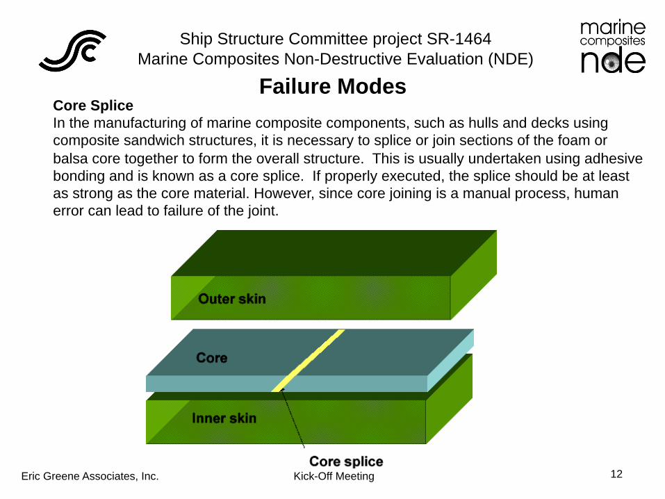
Core Splice In the manufacturing of marine composite components, such as hulls and decks using composite sandwich structures, it is necessary to splice or join sections of the foam or balsa core together to form the overall structure. This is usually undertaken using adhesive bonding and is known as a core splice. If properly executed, the splice should be at least as strong as the core material. However, since core joining is a manual process, human error can lead to failure of the joint.
Failure Modes
Ship Structure Committee project SR-1464 Marine Composites Non-Destructive Evaluation (NDE)
Eric Greene Associates, Inc. Kick-Off Meeting 13
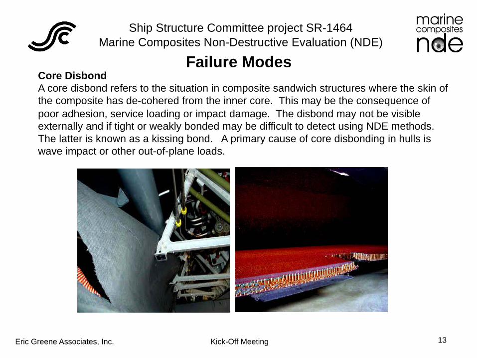
Core Disbond A core disbond refers to the situation in composite sandwich structures where the skin of the composite has de-cohered from the inner core. This may be the consequence of poor adhesion, service loading or impact damage. The disbond may not be visible externally and if tight or weakly bonded may be difficult to detect using NDE methods. The latter is known as a kissing bond. A primary cause of core disbonding in hulls is wave impact or other out-of-plane loads.
Failure Modes

Ship Structure Committee project SR-1464 Marine Composites Non-Destructive Evaluation (NDE)
Eric Greene Associates, Inc. Kick-Off Meeting 14
Core Crushing Composite sandwich structures can use a number of core materials including foam, honeycomb and balsa. The outer skins are adhesively bonded to the core. Loading by flexing, compression or impact may cause crushing of the core, often accompanied by disbonding of the interface. Improperly through-bolted foundations can also cause core crushing. This is known as core-crushing. This damage may not be evident from the surface. Other defects that may occur in the core include: skin to core disbonds, inter-core breakdown and water / ice action breaking cell walls, and open core splices. Core crushing is common following accidently damage to hulls or improper out-of-water storage.
Failure Modes
Ship Structure Committee project SR-1464 Marine Composites Non-Destructive Evaluation (NDE)
Eric Greene Associates, Inc. Kick-Off Meeting 15
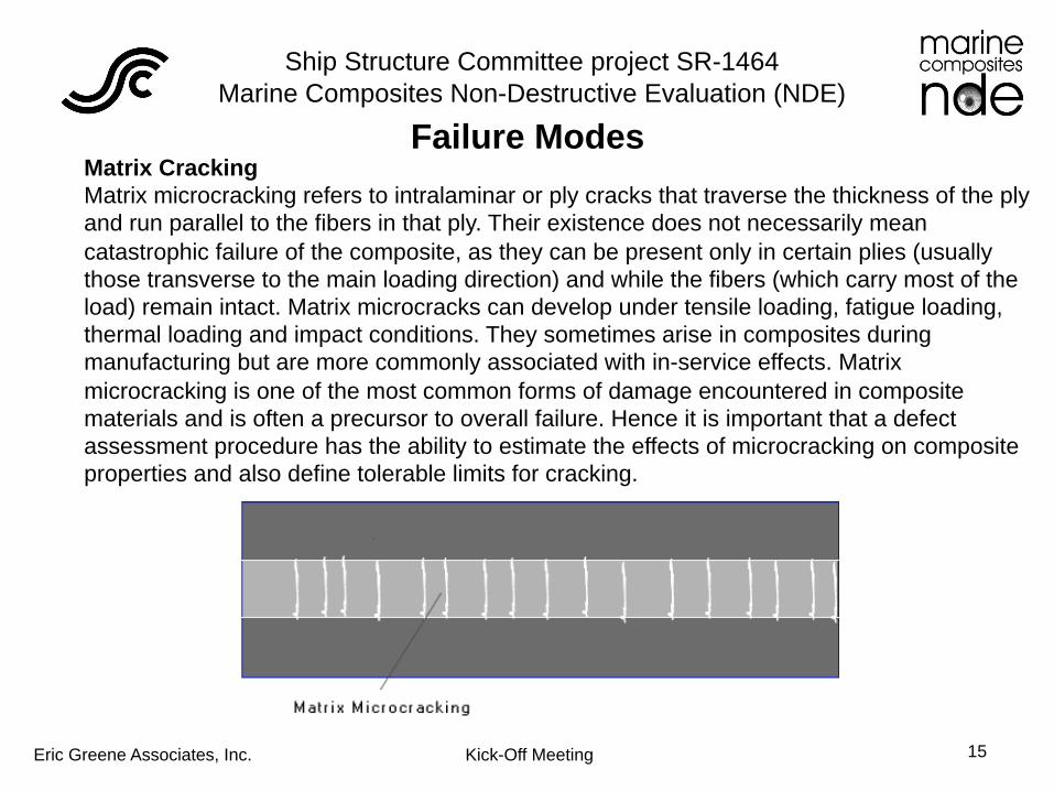
Matrix Cracking Matrix microcracking refers to intralaminar or ply cracks that traverse the thickness of the ply and run parallel to the fibers in that ply. Their existence does not necessarily mean catastrophic failure of the composite, as they can be present only in certain plies (usually those transverse to the main loading direction) and while the fibers (which carry most of the load) remain intact. Matrix microcracks can develop under tensile loading, fatigue loading, thermal loading and impact conditions. They sometimes arise in composites during manufacturing but are more commonly associated with in-service effects. Matrix microcracking is one of the most common forms of damage encountered in composite materials and is often a precursor to overall failure. Hence it is important that a defect assessment procedure has the ability to estimate the effects of microcracking on composite properties and also define tolerable limits for cracking.
Failure Modes

Ship Structure Committee project SR-1464 Marine Composites Non-Destructive Evaluation (NDE)
Eric Greene Associates, Inc. Kick-Off Meeting 16
Kissing Bond A kissing bond refers to the situation where two surfaces have been only partially bonded or are disbonded but touching or in very close proximity. This may be the consequence of poor adhesion, service loading or impact damage. The disbond may not be visible externally and because of it's tightness may be more difficult to detect using NDE methods than a conventional disbond.
The integrity of adhesively bonded composite structures is strongly dependent on good integrity of the bonds. Care and cleanliness in bond preparation is paramount. Any disbonding is likely to exacerbate under service loading or environmental ingress eventually leading to partial separation of the composite layers and failure of the component.
Failure Modes
Ship Structure Committee project SR-1464 Marine Composites Non-Destructive Evaluation (NDE)
Eric Greene Associates, Inc. Kick-Off Meeting 17
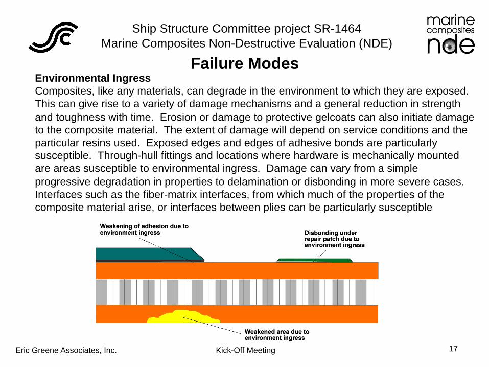
Environmental Ingress Composites, like any materials, can degrade in the environment to which they are exposed. This can give rise to a variety of damage mechanisms and a general reduction in strength and toughness with time. Erosion or damage to protective gelcoats can also initiate damage to the composite material. The extent of damage will depend on service conditions and the particular resins used. Exposed edges and edges of adhesive bonds are particularly susceptible. Through-hull fittings and locations where hardware is mechanically mounted are areas susceptible to environmental ingress. Damage can vary from a simple progressive degradation in properties to delamination or disbonding in more severe cases. Interfaces such as the fiber-matrix interfaces, from which much of the properties of the composite material arise, or interfaces between plies can be particularly susceptible
Failure Modes

Ship Structure Committee project SR-1464 Marine Composites Non-Destructive Evaluation (NDE)
Eric Greene Associates, Inc. Kick-Off Meeting 18
Fiber Wrinkling-Waviness Fiber Wrinkling or waviness refers to the in-plane kinking of the fibers in a ply. Waviness or wrinkling of the fibers can seriously affect laminate strength. This type of defect is particularly of concern in highly stressed defense components and investment has been made in NDE methods such as ultrasonic C-scan image processing to characterize the damage. Resin infused laminates with tight corners are particularly susceptible to fiber wrinkling, as each ply is not individually consolidated as with hand lay-up.
Failure Modes

Ship Structure Committee project SR-1464 Marine Composites Non-Destructive Evaluation (NDE)
Eric Greene Associates, Inc. Kick-Off Meeting 19
Fiber and Ply Misalignment Fiber misalignment refers to local or more extensive misalignment of fibers in the composite material. Ply misalignment refers to the situation where a whole or part of a ply or layer of the composite is misaligned. This is produced as a result of mistakes made in the lay-up of the component plies. This alters the overall stiffness and strength of the laminate.
Fiber and ply misalignment are potentially disastrous defects but are rarely encountered due to high standards of quality control. Often, a cutout of the material is examined to ensure that the correct ply stacking sequence was used. If a composite vessel exhibits signs of structural deficiencies in-service, fiber and ply alignment can only be verified via burn-out tests (not NDE) of a sufficiently large coupon.
Failure Modes

Ship Structure Committee project SR-1464 Marine Composites Non-Destructive Evaluation (NDE)
Eric Greene Associates, Inc. Kick-Off Meeting 20
Incorrect Cure Incomplete cure refers to the situation where the matrix has been incompletely cured due to incorrect curing cycle (catalyst mixing, temperature) or faulty resin materials. This may be localized or affect the whole component. The result will be reduced strength and toughness. Incomplete cure is also an issue in adhesive processes using resin based adhesives affecting the integrity of end-fittings and adhesive joints.
The degree of matrix cure is usually determined with a Barcol hardness tester. A part with under-cured resin can sometimes be “post-cured” with the application of heat or a “hot” batch of resin but often the part must be rejected. An under-cured styrene-based resin system will often continue to emit a styrene odor, especially in the interior of recreational boats.
Failure Modes

Ship Structure Committee project SR-1464 Marine Composites Non-Destructive Evaluation (NDE)
Eric Greene Associates, Inc. Kick-Off Meeting 21
Excess Resin Fabrication methods for composites are designed to provide a uniform distribution of fibers in a resin matrix. Mechanical properties depend on the fiber volume fraction. Load transfer across the fiber matrix interfaces are a key feature giving rise to the good strength and toughness characteristics of composites. It is a natural consequence of manufacturing methods that local variations in fiber or resin content will occur. Where the resin content is above design limits, this is referred to as excess resin.
Failure Modes
Ship Structure Committee project SR-1464 Marine Composites Non-Destructive Evaluation (NDE)
Eric Greene Associates, Inc. Kick-Off Meeting 22
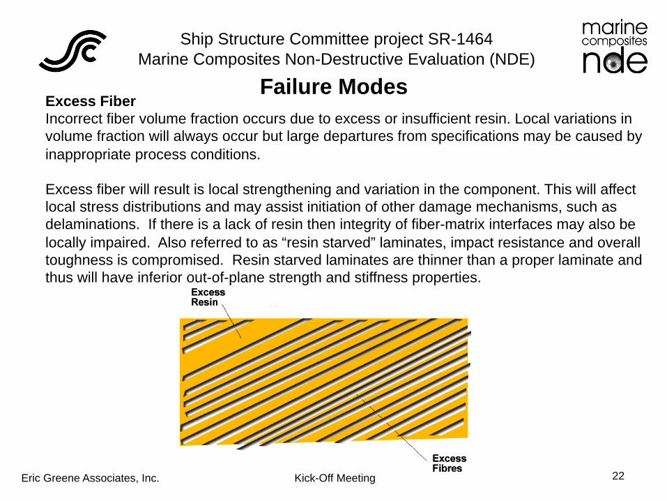
Excess Fiber Incorrect fiber volume fraction occurs due to excess or insufficient resin. Local variations in volume fraction will always occur but large departures from specifications may be caused by inappropriate process conditions.
Excess fiber will result is local strengthening and variation in the component. This will affect local stress distributions and may assist initiation of other damage mechanisms, such as delaminations. If there is a lack of resin then integrity of fiber-matrix interfaces may also be locally impaired. Also referred to as “resin starved” laminates, impact resistance and overall toughness is compromised. Resin starved laminates are thinner than a proper laminate and thus will have inferior out-of-plane strength and stiffness properties.
Failure Modes

Ship Structure Committee project SR-1464 Marine Composites Non-Destructive Evaluation (NDE)
Eric Greene Associates, Inc. Kick-Off Meeting 23
Lightning Strike Damage Composite boats typically have not been too concerned with lightning strikes, as E-glass laminates do not conduct electricity. Current generated from lightning strikes will travel along designed ground paths and not enter the laminate. The use of carbon fibers in laminates presents a conductivity path within the laminate, which leads to concerns about laminate integrity after a strike. The intense heat generated within the laminate can cause moisture to gasify, creating local voids or delaminations.
High-end racing sailboats have carbon fiber masts and skins for the hull and deck laminates. Ground paths can pass through these structures and typically are first discovered via visual examination. Follow-up detailed NDE can indicate a compromise in overall structural integrity, especially if an unaffected symmetrical structure is available for comparison. A larger-scale NDE technique is required to evaluate lightning strike damage in large marine structures.
Failure Modes

Ship Structure Committee project SR-1464 Marine Composites Non-Destructive Evaluation (NDE)
Eric Greene Associates, Inc. Kick-Off Meeting 24
Correlation of Test Results
Ship Structure Committee project SR-1464 Marine Composites Non-Destructive Evaluation (NDE)
Eric Greene Associates, Inc. Kick-Off Meeting 25
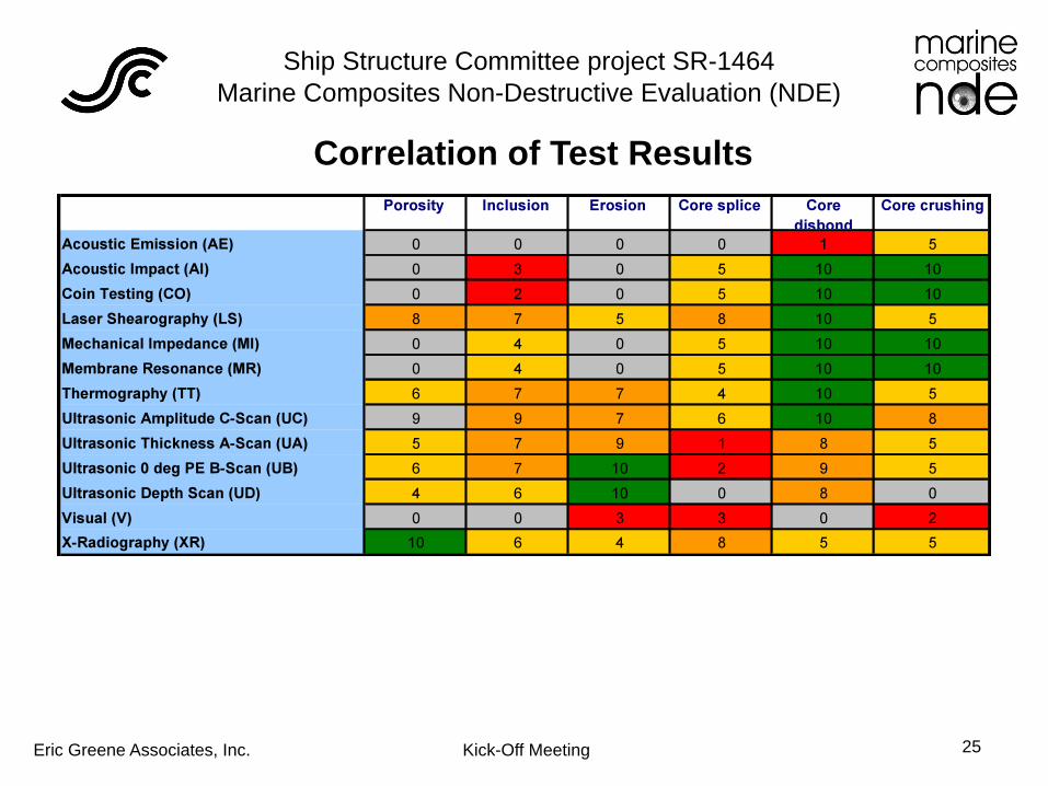
Correlation of Test Results
Ship Structure Committee project SR-1464 Marine Composites Non-Destructive Evaluation (NDE)
Eric Greene Associates, Inc. Kick-Off Meeting 26
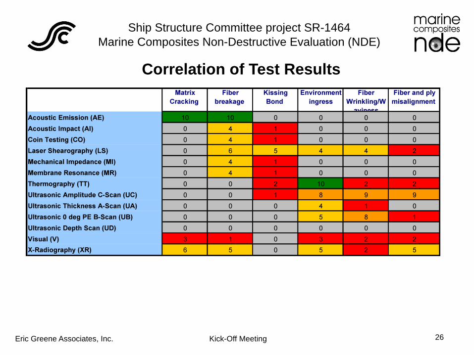
Correlation of Test Results

Ship Structure Committee project SR-1464 Marine Composites Non-Destructive Evaluation (NDE)
Eric Greene Associates, Inc. Kick-Off Meeting 27
Correlation of Test Results

Ship Structure Committee project SR-1464 Marine Composites Non-Destructive Evaluation (NDE)
Eric Greene Associates, Inc. Kick-Off Meeting 28
Visual Inspection Visual inspection refers to the simple examination of a component for defects using the human eye. The term enhanced visual inspection is used where the inspection is aided by artificial tools, such as closed circuit TV cameras, special lighting systems, endoscopes and automated defect recognition tools. Visual inspection is the most common form of inspection for composites and other materials systems. Increasingly, digital cameras, CCTV or video cameras are used either for monitoring or to provide a permanent record of the inspection. Visual inspection is widely used for inspection of composite parts, particularly after manufacture. It is an accepted and useful part of quality control. There are established standards such as ASTM D 2563-1994 (rev 2002). The chief advantages of visual inspection are its speed, simplicity and ability to detect a variety of flaws. Coverage may be limited. Speed is usually but not always faster than other NDE methods.
Although more commonly used with metallic construction, dye penetrant can be used to highlight surface cracks in composite construction

Ship Structure Committee project SR-1464 Marine Composites Non-Destructive Evaluation (NDE)
Eric Greene Associates, Inc. Kick-Off Meeting 29
This is by far the most utilized method for discovering damage to a fiberglass boat. This works fine for the exterior of the hull and deck but can be problematic with heavily outfitted interiors. Features that make interior inspection difficult include foamed void spaces, liners & insulation, tanks, joinery, plumbing and wiring. Exterior visual inspection can be difficult if you have struck a submerged object below the waterline and the boat is still in the water. Visual inspection can be tricky for the novice, as composite construction damage can look worse than it is structurally and conversely, the extent of delamination can be greater than what meets the eye.
The U.S. Navy requires that glass reinforced laminates built for them not use colored gel coats to make visual inspection possible for detecting delaminations, voids, resin rich or starved areas, fiber misalignment, bridging and under cure. However, they recognize that visual inspection can be subjective and recommend that any potential problems be further investigated with more precise methods, such as ultrasonic testing.
Visual Inspection

Ship Structure Committee project SR-1464 Marine Composites Non-Destructive Evaluation (NDE)
Eric Greene Associates, Inc. Kick-Off Meeting 30
ASTM standard D 2563 gives the following range of defects to be detected by visual inspection, including acceptance limits:
Delaminations Edge delamination Crazing Dry spot Foreign inclusion Fracture Air-bubble (void) Blister Thermal damage (burn) Fish eye Lack of fill out Orange peel Pimple Pit (pinhole) Porosity (pinhole) pre-gel Resin pocket Resin rich edge Shrink mark (sink) Wash Wrinkles Scratch Short
Visual Inspection

Ship Structure Committee project SR-1464 Marine Composites Non-Destructive Evaluation (NDE)
Eric Greene Associates, Inc. Kick-Off Meeting 31
Coin or Tap Testing One simple technique not to be overlooked is that of coin or tap-testing . Where a coin is used the method is known as coin tap testing. This is the simplest of local vibration tests, where the inspector listens to the sound made when the surface is tapped by anything from a coin to a sounding hammer. Having much in common with mechanical impedance, this essentially monitors the influence of the defect on the damping of an impact. A defect is recognized by the duller sound produced over a delamination (a lack of higher frequency response). Experienced inspectors can identify defects with a good reliability but the method is highly operator-dependent.

Ship Structure Committee project SR-1464 Marine Composites Non-Destructive Evaluation (NDE)
Eric Greene Associates, Inc. Kick-Off Meeting 32
Ultrasonics Ultrasonic amplitude C-scan refers to the measurement of the attenuation of ultrasound through the composite material with the data plotted in the form of a C-Scan, which resembles a planar view looking through the top surface of the specimen. Ultrasound pulses are reflected by interfaces between materials of different properties. In the case of delaminations and disbonds, this can cause a discrete reflection from a particular depth in the material. Such a reflection also results in a loss of transmission through the material. Porosity and voids do not produce a discrete reflection but scatter the ultrasound in a range of directions, also resulting in a transmission loss. These transmission losses can be detected by mapping the transmitted signal over the whole structure.

Ship Structure Committee project SR-1464 Marine Composites Non-Destructive Evaluation (NDE)
Eric Greene Associates, Inc. Kick-Off Meeting 33
Shearography Laser shearography is a non-contact, inspection technique that presents a visual qualitative map of the strain field of the surface of the structure in response to an applied stress. Subsurface features such as core splices, bulkheads and defective areas affect and distort the surface strain field and are therefore monitored. The sensitivity vector of these shearography systems is predominately out-of-plane; it is therefore sensitive to the weakest vector of the bonded laminate. Shearography derives its name from the requirement to laterally displace and overlap images, or to shear them. This gives the in-plane component.
Ship Structure Committee project SR-1464 Marine Composites Non-Destructive Evaluation (NDE)
Eric Greene Associates, Inc. Kick-Off Meeting 34
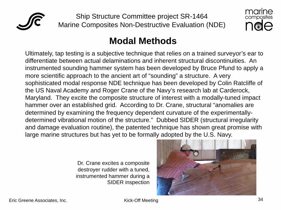
Modal Methods Ultimately, tap testing is a subjective technique that relies on a trained surveyor’s ear to differentiate between actual delaminations and inherent structural discontinuities. An instrumented sounding hammer system has been developed by Bruce Pfund to apply a more scientific approach to the ancient art of “sounding” a structure. A very sophisticated modal response NDE technique has been developed by Colin Ratcliffe of the US Naval Academy and Roger Crane of the Navy’s research lab at Carderock, Maryland. They excite the composite structure of interest with a modally-tuned impact hammer over an established grid. According to Dr. Crane, structural “anomalies are determined by examining the frequency dependent curvature of the experimentally-determined vibrational motion of the structure.” Dubbed SIDER (structural irregularity and damage evaluation routine), the patented technique has shown great promise with large marine structures but has yet to be formally adopted by the U.S. Navy.
Dr. Crane excites a composite destroyer rudder with a tuned,
instrumented hammer during a SIDER inspection

Ship Structure Committee project SR-1464 Marine Composites Non-Destructive Evaluation (NDE)
Eric Greene Associates, Inc. Kick-Off Meeting 35
Mechanical Impedance Mechanical Impedance is a method of acoustic impact testing that is used in a number of commercial bond testers. Continuous excitation of the structure allows an analysis of its response to a particular frequency. Then sweeping this frequency gives information about resonances in the structure. Defects will cause changes to those resonances and these can be monitored during the inspection. Mechanical Impedance Analysis measures the stiffness and mass of the material being tested. The output is measured in both amplitude and phase. The method is simple to apply and requires no couplant.
Membrane Resonance is used mainly for the inspection of aircraft structures and operates on the principle of exciting a thickness resonance in a multi-layered structure. A piezoelectric probe, excited by a swept frequency signal, is coupled to the surface of the inspected structure using a coupling agent. A typical “bond tester” that relies on membrane resonance is shown here.
Ship Structure Committee project SR-1464 Marine Composites Non-Destructive Evaluation (NDE)
Eric Greene Associates, Inc. Kick-Off Meeting 36
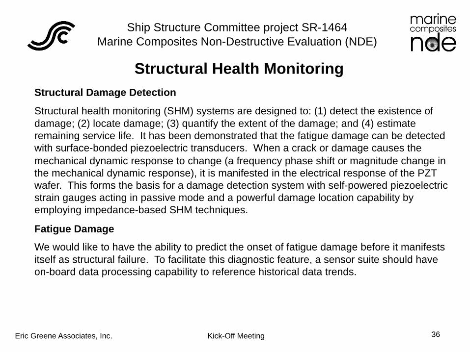
Structural Health Monitoring Structural Damage Detection
Structural health monitoring (SHM) systems are designed to: (1) detect the existence of damage; (2) locate damage; (3) quantify the extent of the damage; and (4) estimate remaining service life. It has been demonstrated that the fatigue damage can be detected with surface-bonded piezoelectric transducers. When a crack or damage causes the mechanical dynamic response to change (a frequency phase shift or magnitude change in the mechanical dynamic response), it is manifested in the electrical response of the PZT wafer. This forms the basis for a damage detection system with self-powered piezoelectric strain gauges acting in passive mode and a powerful damage location capability by employing impedance-based SHM techniques.
Fatigue Damage
We would like to have the ability to predict the onset of fatigue damage before it manifests itself as structural failure. To facilitate this diagnostic feature, a sensor suite should have on-board data processing capability to reference historical data trends.

Ship Structure Committee project SR-1464 Marine Composites Non-Destructive Evaluation (NDE)
Eric Greene Associates, Inc. Kick-Off Meeting 37
Extreme Event Damage
Ship structural damage is often caused by an extreme event, such as impact from a large wave or triggering of a structural resonance, as shown with the strain gauge data. The timescales for the data are 8 seconds (left) and 20 seconds (right), illustrating the need for high sampling rate to capture transient data. Note the high-frequency strain data superimposed over the low-frequency hull girder (hogging/sagging) measurements.
A Structural Health Monitoring (SHM) system will record transient data and save that information at the sensor suite only when triggered by an extreme event. Otherwise, data will be recorded at frequencies necessary for long-term trending.
Structural Health Monitoring

Ship Structure Committee project SR-1464 Marine Composites Non-Destructive Evaluation (NDE)
Eric Greene Associates, Inc. Kick-Off Meeting 38 Strain Data from Catamaran Wet Deck and Composite Skjold Class SES
Structural Damage Detection using Electrical Impedance Measurement Fatigue Crack Initiated at Bilge Web
Detected by Piezo Gauges
Structural Health Monitoring

Ship Structure Committee project SR-1464 Marine Composites Non-Destructive Evaluation (NDE)
Eric Greene Associates, Inc. Kick-Off Meeting 39
Thermography Thermography techniques use infra-red sensitive cameras to monitor the apparent surface temperature of a composite structure. The thermal response from a component is altered in the presence of a defect. To see defects at a reasonable resolution it is necessary to inject a pulse of heat into the component and use a high quality thermal imaging camera. This is the basis of transient thermography, the most common thermography method applied to composite materials, also known as pulse-video thermography. There are a number of ways to inject heat including, flash lamp, induction heater and hot-air gun.

Ship Structure Committee project SR-1464 Marine Composites Non-Destructive Evaluation (NDE)
Eric Greene Associates, Inc. Kick-Off Meeting 40
X-ray is the most commonly used radiographic technique in NDT, and uses an X-ray source and photographic X-ray film to obtain shadowgraph images of the specimen (radiographs). X-rays are attenuated by a mechanism involving changes in the energy states of electrons in the X-ray beam. X-radiography therefore relies on detecting changes in the electron density within the material along the length of the beam.
X-radiography is primarily used in composites for detection of cracking, particularly matrix cracking and damage associated with impact as well as delaminations. For these applications it is normal to use an absorbent penetrant such as di-iodomethane or di-bromomethane. Matrix cracking is not normally evident on ultrasonic C-scan inspection.
Composites are very transparent to X-rays. For this reason you need low energy X-rays and specialist detectors for example with beryllium window so that the X-rays are not absorbed. As neither delaminations nor disbonds affect that electron distribution significantly, these two defects are virtually invisible to X-rays.
X-ray

Ship Structure Committee project SR-1464 Marine Composites Non-Destructive Evaluation (NDE)
Eric Greene Associates, Inc. Kick-Off Meeting 41
Moisture meters are perhaps the most debatable diagnostic tools used by marine surveyors. Yacht brokers hate them as many deals have fallen through because a survey concluded that moisture was trapped in a boat’s skin laminate or core. Perspective buyers rely on moisture meter surveys to alert them to potential water in the laminate, especially with sandwich construction. This is the opinion of James G. Merritt, a marine surveyor in Austin Texas: “After using a moisture meter on over 1,000 surveys, I have yet to see a recently-hauled boat that indicated anything less than ‘high’ (7+ on a scale of 1 - 10) on surfaces below the waterline. These readings have been taken with a variety of meters……. The end result is that I ignore meter readings below the waterline while still paying close attention to exterior surfaces above the waterline, particularly around through-hull fittings and any deck hardware.” With fiberglass, meter readings will always be on a “relative” scale and destructive testing (i.e. cutting open the laminate) is required to get an absolute reading.
Moisture meters don’t work with conductive laminates, such as carbon fiber.
Moisture Meters

Ship Structure Committee project SR-1464 Marine Composites Non-Destructive Evaluation (NDE)
Eric Greene Associates, Inc. Kick-Off Meeting 42
NDE Tools
Moisture Meter
Ultrasonic Thickness Gauge
Thermography

Ship Structure Committee project SR-1464 Marine Composites Non-Destructive Evaluation (NDE)
Eric Greene Associates, Inc. Kick-Off Meeting 43
High Performance Composite Military Ships

Ship Structure Committee project SR-1464 Marine Composites Non-Destructive Evaluation (NDE)
Eric Greene Associates, Inc. Kick-Off Meeting 44
DDG 1000 Deckhouse Engineering Development
Model (EDM)
• Integrated Deckhouse and Apertures (IDHA) was 1 of 10 critical EDM’s
• Purpose was to reduce technical risk prior to Ship System Critical Design Review
• Numerous test events ranging in scale from coupon test to full-scale test articles
• Testing complimented with modeling and simulation
Karl Reque

Ship Structure Committee project SR-1464 Marine Composites Non-Destructive Evaluation (NDE)
Eric Greene Associates, Inc. Kick-Off Meeting 45
LPD 17 Advanced Enclosed Mast System
Ship Structure Committee project SR-1464 Marine Composites Non-Destructive Evaluation (NDE)
Eric Greene Associates, Inc. Kick-Off Meeting 46
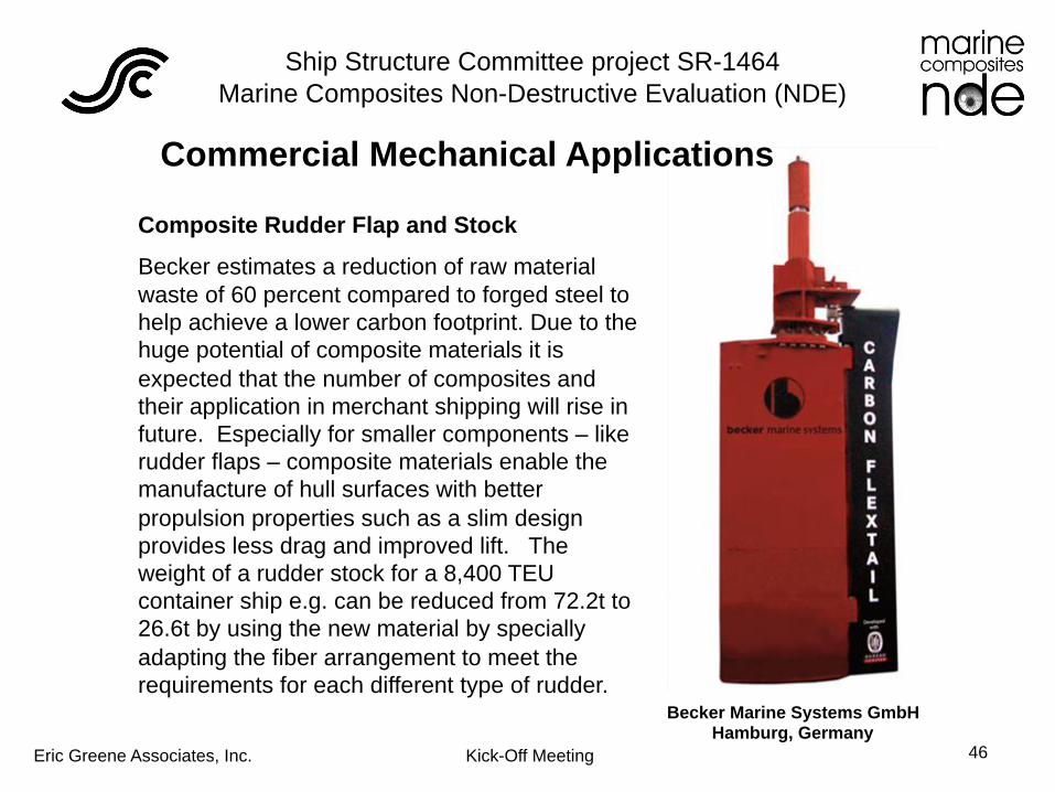
Commercial Mechanical Applications
Composite Rudder Flap and Stock
Becker estimates a reduction of raw material waste of 60 percent compared to forged steel to help achieve a lower carbon footprint. Due to the huge potential of composite materials it is expected that the number of composites and their application in merchant shipping will rise in future. Especially for smaller components – like rudder flaps – composite materials enable the manufacture of hull surfaces with better propulsion properties such as a slim design provides less drag and improved lift. The weight of a rudder stock for a 8,400 TEU container ship e.g. can be reduced from 72.2t to 26.6t by using the new material by specially adapting the fiber arrangement to meet the requirements for each different type of rudder.
Becker Marine Systems GmbH Hamburg, Germany

Ship Structure Committee project SR-1464 Marine Composites Non-Destructive Evaluation (NDE)
Eric Greene Associates, Inc. Kick-Off Meeting 47
Define Allowable Defect Size/Characterization
Defects to include: • Voids • Delamination/Kissing Bond • Water
Defects characterization: • Diameter • Thickness • Density of adjacent defects
Develop Trade-Off Studies for Detection Resolution • Defect size vs. structure reliability • Measurement accuracy vs. cost, time
Ship Structure Committee project SR-1464 Marine Composites Non-Destructive Evaluation (NDE)
Eric Greene Associates, Inc. Kick-Off Meeting 48
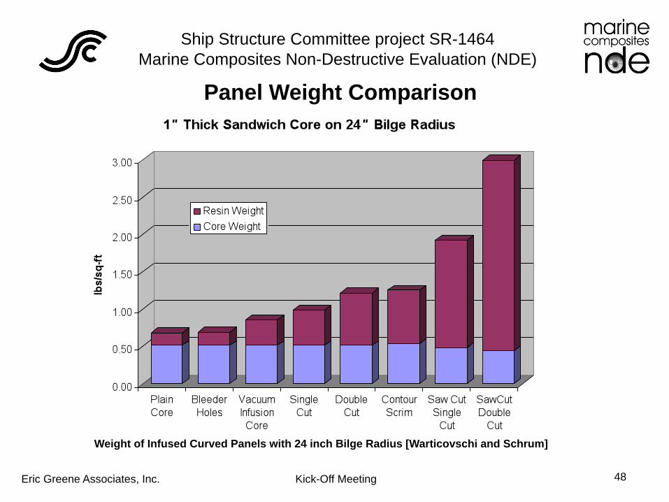
Weight of Infused Curved Panels with 24 inch Bilge Radius [Warticovschi and Schrum]
Panel Weight Comparison
Ship Structure Committee project SR-1464 Marine Composites Non-Destructive Evaluation (NDE)
Eric Greene Associates, Inc. Kick-Off Meeting 49
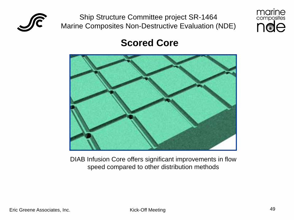
Scored Core
DIAB Infusion Core offers significant improvements in flow speed compared to other distribution methods

Ship Structure Committee project SR-1464 Marine Composites Non-Destructive Evaluation (NDE)
Eric Greene Associates, Inc. Kick-Off Meeting 50
Design Panels with Defects for Evaluation
Test Panels • Solid E-glass • Foam/balsa/honeycomb core • E-glass and carbon skins • Resin infused
Defects Examined • Delaminated skins • Voids • Skin/core disbond • Water intrusion • Core shear failure • Impact damage • Lightning
Ship Structure Committee project SR-1464 Marine Composites Non-Destructive Evaluation (NDE)
Eric Greene Associates, Inc. Kick-Off Meeting 51
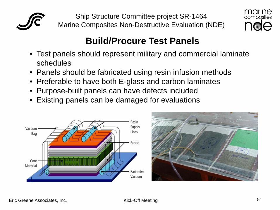
Build/Procure Test Panels • Test panels should represent military and commercial laminate
schedules • Panels should be fabricated using resin infusion methods • Preferable to have both E-glass and carbon laminates • Purpose-built panels can have defects included • Existing panels can be damaged for evaluations

Ship Structure Committee project SR-1464 Marine Composites Non-Destructive Evaluation (NDE)
Eric Greene Associates, Inc. Kick-Off Meeting 52
Damage Test Panels Impact Test Arrangement used for SSC-442 Passive Fire Protection Build New Panels
• Solid E-glass • Foam/balsa/honeycomb core • E-glass and carbon skins • Resin infused
Damage Existing Panels • Impact damage via drop weight • Delaminations and core shear via
bend failure • Inject water under pressure

Ship Structure Committee project SR-1464 Marine Composites Non-Destructive Evaluation (NDE)
Eric Greene Associates, Inc. Kick-Off Meeting 53
NDE Test & Video
• Inspect “damaged” panels at facilities of instrumentation manufacturers
• Video tape inspection process
• Document data reduction
• Work with marine surveyors to document in-field inspections
Ship Structure Committee project SR-1464 Marine Composites Non-Destructive Evaluation (NDE)
Eric Greene Associates, Inc. Kick-Off Meeting 54
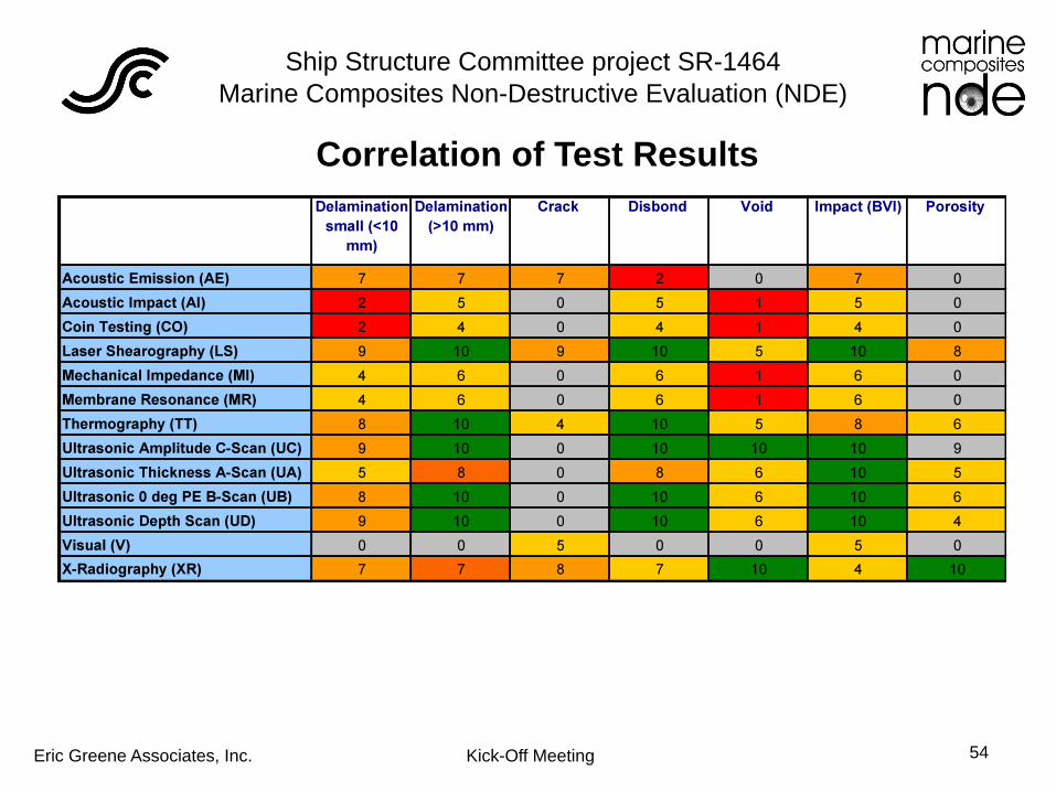
Correlation of Test Results

Ship Structure Committee project SR-1464 Marine Composites Non-Destructive Evaluation (NDE)
Eric Greene Associates, Inc. Kick-Off Meeting 55
Project Documentation (Web Video Content)
• Web site will offer opportunity to present videos on NDE inspection techniques
• Site will provide overview of methods and failure modes that can be examined
• Reference material will be available in Acrobat format
• Links to vendors, associations, and inspection organizations will be provided

Ship Structure Committee project SR-1464 Marine Composites Non-Destructive Evaluation (NDE)
Eric Greene Associates, Inc. Kick-Off Meeting 56
Final Report
Final Report will be prepared in accordance with “STANDARDS FOR THE PREPARATION AND PUBLICATION OF SSC TECHNICAL REPORTS,” Ship Structure Committee, October 2000
Report Format SSC Cover Inside Self-Cover (provided at printing by SSC)
i Chairman SSC letter ii Technical Report Documentation Page iii Metric Conversion Factors iv Table of Contents, List of Illustrations, list of Tables, List of Abbreviations and Symbols
1-1 Introduction Conclusions Main Text Recommendations
A-1 Appendices Glossary Index References Bibliography Project Technical Committee Recent SSC Publications back cover