Ship Stability for Masters and Mates - dl.kashti.ir Stability for Masters and Mates... · Ship...
465
Ship Stability for Masters and Mates
Transcript of Ship Stability for Masters and Mates - dl.kashti.ir Stability for Masters and Mates... · Ship...

Ship Stability for Mastersand Mates

Ship Stability forMasters and MatesFifth edition
Captain D. R. Derrett
Revised by Dr C. B. Barrass
OXFORD AUCKLAND BOSTON JOHANNESBURG MELBOURNE NEW DELHI
��������������� ���������� ����� ������ ���� ������ ��� ������ �������� !����� ��"���� # $%�$%�$&% ��!����� �� '��� (���������� ��� ������������ ��"������) ���
*���� +�"������ ", -������� #����� � ��� %./&0���� ������� 1 �����2 %.3�'�+������ %.34� %.3�� %.33� %.3.� %.��*����� ������� %.�&'�+������ %.��*���� +�"������ ", '��� (���������� ��� ������������ ��"������) ��� %..$'�+������ %..$ 1�����2� %..%� %..4� %..3� %..�� %...*���� ������� %...'�+������ �$$$ 1�����2� �$$%
� �5 '5 ������� %.�&� %..$� %... ��� '��� (������������� ������������ ��"������) ��� %...
�� ��)��� �����!��5 6� +��� �� ���� +�"�������� �, "� ��+������� �� ��, ������� ��� 1��������)+������+,��) �� ������) �� ��, ���� ", ���������� ���� ��� ������� �� ��� ����������, �� �����������,�� �� � ����� ��� �� ���� +�"��������2 ������� ���������� +�� ������ �� ��� ��+,��)�� ������ ����+��� ���������� ���� ��� +��!������ �� ��� 7�+,��)�������)�� ��� ������� �� %.�� �� ����� ��� ��� � �� �������� ������ ", ��� 7�+,��)�� ��������) )���, ����.$ 0������� 7���� '���� ������� (�)���� �%� $��5 ++��������� ��� ��� ��+,��)�� ������8� ������� +�� �������� ��+������ ��, +��� �� ���� +�"�������� ������ "� ����������� ��� +�"�������
������� ����� ��� ����� �� �������� � �� ������)�� ������ ��� ���� "��9 �� �!����"�� ��� ��� ������� ��"���,
����� � � ������ ��� ����� �� ������� � �� ������)�� ������ ��� ���� "��9 �� �!����"�� ��� ��� ��"���, �� 7��)����
:-�6 $ 3�$/ &%$% $
0,+�������) ��� ������9 �������� ", ��!�� ;��)��� ���������� �������� -�����9������� ��� "���� �� ;���� ������� ", �������� ;��������� -����,
� "�� �� ��� '��� (���!��� +�� )���+

ContentsPreface viiIntroduction ixShip types and general characteristics xi
1 Forces and moments 12 Centroids and the centre of gravity 93 Density and speci®c gravity 194 Laws of ¯otation 225 Effect of density on draft and displacement 336 Transverse statical stability 437 Effect of free surface of liquids on stability 508 TPC and displacement curves 559 Form coef®cients 6110 Simpson's Rules for areas and centroids 6811 Final KG 9412 Calculating KB, BM and metacentric diagrams 9913 List 11414 Moments of statical stability 12415 Trim 13316 Stability and hydrostatic curves 16217 Increase in draft due to list 17918 Water pressure 18419 Combined list and trim 18820 Calculating the effect of free surface of liquids (FSE) 19221 Bilging and permeability 20422 Dynamical stability 21823 Effect of beam and freeboard on stability 22424 Angle of loll 22725 True mean draft 23326 The inclining experiment 23827 Effect of trim on tank soundings 243

28 Drydocking and grounding 24629 Second moments of areas 25630 Liquid pressure and thrust. Centres of pressure 26631 Ship squat 27832 Heel due to turning 28733 Unresisted rolling in still water 29034 List due to bilging side compartments 29635 The Deadweight Scale 30236 Interaction 30537 Effect of change of density on draft and trim 31538 List with zero metacentric height 31939 The Trim and Stability book 32240 Bending of beams 32541 Bending of ships 34042 Strength curves for ships 34643 Bending and shear stresses 35644 Simpli®ed stability information 372
Appendix I Standard abbreviations and symbols 378Appendix II Summary of stability formulae 380Appendix III Conversion tables 387Appendix IV Extracts from the M.S. (Load Lines) Rules, 1968 388Appendix V Department of Transport Syllabuses (Revised April
1995) 395Appendix VI Specimen examination papers 401Appendix VII Revision one-liners 429Appendix VIII How to pass exams in Maritime Studies 432Appendix IX Draft Surveys 434Answers to exercises 437Index 443
vi Contents

����������� ���� �� ����� ������ �� ���� ��� ���� �� ��� �� ����� ����� ������ �� ����� � ���� ��� ���� � �� � ����� �� ������ � ��� ���� ��������� �� ������� �� �� ���� ������ � � �� ��� �������� � ����� ����!�� ��� ��!� �"������ ������ �� #����� $����������� ����� �� ��� ������ � ��� ���%��� � ���� ��!� ��� �� �� ���� �� �� ����� ���� � ���� ����� �� ��� �������� �� ������ ���� ��� ���� ����� ����� �� �� ��� �� � ����� ��&��&��� ��������� �������� �"�� ��� ����� ���� ���� ����� �� �� �� �� ����� ���� ��
'�� ��������� � �� ��� �� ��� �� ����� �� (� #%����)� $���� ������� �� �������� �� ������� ��� �������� ������ ��� � ���#� ���� �� � ���� *����� *�� #+,-� �������� �� ����� �����������.��� #�/� 0�" ) 123 � 143� #��� � $����� � *����� *�� #2244��������� ����� ����������� #"���� 5��������� ��������� ����� � �"���� ��� ��� ������ � �� � ���� �"�� ��� $���������
$������ �"�� ��� ���� ��!� � '��� ��" / � �������� ���� � �������� �� ��� $������� 6�������� � '������� 1$6'3� ���� � 7������
������������ ���� ����� ��� ���� � ���� � �!��� $�������� 8#� 7# � �# ���� �� ����� 9�� ���� � ���� :� ������ � $�������� ���� ������� 8#:� 7#: � �#: ���� �� ���� �� �� ��� ��� �� ������ ��� ������� �� (� �� � ����" 0�) �� � �!��� $�������� ��� ����" 0:)�� ��� :� ������ � $������� ��"� � ������
�� 8� 8��


IntroductionCaptain D. R. Derrett wrote the standard text book, Ship Stability forMasters and Mates. In this 1999 edition, I have revised several areas of hisbook and introduced new areas/topics in keeping with developments overthe last nine years within the shipping industry.This book has been produced for several reasons. The main aims are as
follows:
1. To provide knowledge at a basic level for those whose responsibilitiesinclude the loading and safe operation of ships.
2. To give maritime students and Marine Of®cers an awareness ofproblems when dealing with stability and strength and to suggestmethods for solving these problems if they meet them in the day-to-dayoperation of ships.
3. To act as a good, quick reference source for those of®cers who obtainedtheir Certi®cates of Competency a few months/years prior to joiningtheir ship, port authority or drydock.
4. To help Masters, Mates and Engineering Of®cers prepare for theirSQA/MSA exams.
5. To help students of naval architecture/ship technology in their studieson ONC, HNC, HND and initial years on undergraduate degree courses.
6. When thinking of maritime accidents that have occurred in the last fewyears as reported in the press and on television, it is perhaps wise topause and remember the proverb `Prevention is better than cure'. If thisbook helps in preventing accidents in the future then the efforts ofCaptain Derrett and myself will have been worthwhile.
Finally, I thought it would be useful to have a table of ship types (see nextpage) showing typical deadweights, lengths, breadths, Cb values anddesigned service speeds. It gives an awareness of just how big theseships are, the largest moving structures made by man.It only remains for me to wish you, the student, every success with your
Maritime studies and best wishes in your chosen career. Thank you.
C. B. Barrass


Ship types and generalcharacteristicsThe table below indicates the characteristics relating to several merchantships operating today.The ®rst indicator for a ship is usually her deadweight; closely followed
by her LBP and Cb values.
Type of ship Typical DWT LBP BR. MLD Typical Cb Service speedor name (tonnes or m3) (m) (m) fully loaded (knots)
ULCC, VLCC 565 000 440 to 250 70 to 40 0.85 to 0.82 13 to 1534and supertankers to 100 000
Medium sized 100 000 250 to 175 40 to 25 0.82 to 0.80 15 to 1534oil tankers to 50 000
OBO carriers up to 200 to 300 up to 45 0.78 to 0.80 15 to 16173 000
Ore carriers up to 200 to 320 up to 58 0.79 to 0.83 1412 to 15 12
323 000General cargo 3000 to 100 to 150 15 to 25 0.700 14 to 16ships 15 000
Lique®ed natural 130 000m3 up to 280 46 to 25 0.66 to 0.68 2034 to 16gas (LNG) and to 75 000m3
lique®ed petroleum(LPG) ships
Passenger liners 5000 to 200 to 300 20 to 40 0.60 to 0.64 24 to 30(2 examples below) 20 000
QE2 (built (1970) 15 520 270 32 0.600 2812Oriana (built 1994) 7270 224 32.2 0.625 24Container ships 10 000 to 200 to 300 30 to 45 0.56 to 0.60 20 to 28
72 000Roll on/roll off 2000 to 100 to 180 21 to 28 0.55 to 0.57 18 to 24car and passenger 5000ferries
# 1998 Dr C. B. Barrass


Chapter 1
Forces and momentsThe solution of many of the problems concerned with ship stabilityinvolves an understanding of the resolution of forces and moments. Forthis reason a brief examination of the basic principles will be advisable.
ForcesA force can be de®ned as any push or pull exerted on a body. The S.I. unit offorce is the Newton, one Newton being the force required to produce in amass of one kilogram an acceleration of one metre per second per second.When considering a force the following points regarding the force must beknown:
(a) The magnitude of the force,(b) The direction in which the force is applied, and(c) The point at which the force is applied.
The resultant force. When two or more forces are acting at a point, theircombined effect can be represented by one force which will have the sameeffect as the component forces. Such a force is referred to as the `resultantforce', and the process of ®nding it is called the `resolution of thecomponent forces'.The resolution of forces. When resolving forces it will be appreciated that a
force acting towards a point will have the same effect as an equal forceacting away from the point, so long as both forces act in the same directionand in the same straight line. Thus a force of 10 Newtons (N) pushing tothe right on a certain point can be substituted for a force of 10 Newtons (N)pulling to the right from the same point.
(a) Resolving two forces which act in the same straight lineIf both forces act in the same straight line and in the same direction theresultant is their sum, but if the forces act in opposite directions theresultant is the difference of the two forces and acts in the direction of thelarger of the two forces.

Example 1Whilst moving an object one man pulls on it with a force of 200 Newtons, andanother pushes in the same direction with a force of 300 Newtons. Find theresultant force propelling the object.
Component forces 300N A 200N
The resultant force is obviously 500 Newtons, the sum of the two forces, andacts in the direction of each of the component forces.
Resultant force 500N A or A 500N
Example 2A force of 5 Newtons is applied towards a point whilst a force of 2 Newtons isapplied at the same point but in the opposite direction. Find the resultant force.
Component forces 5N A 2N
Since the forces are applied in opposite directions, the magnitude of theresultant is the difference of the two forces and acts in the direction of the 5Nforce.
Resultant force 3N A or A 3N
(b) Resolving two forces which do not act in the same straight lineWhen the two forces do not act in the same straight line, their resultant canbe found by completing a parallelogram of forces.
Example 1A force of 3 Newtons and a force of 5N act towards a point at an angle of 120degrees to each other. Find the direction and magnitude of the resultant.
Ans. Resultant 4.36N at 36� 34 120 to the 5N force.
Note. Notice that each of the component forces and the resultant all acttowards the point A.
2 Ship Stability for Masters and Mates
Fig. 1.1
<>
>>
E E
E
E
EE
��
� �

Example 2A ship steams due east for an hour at 9 knots through a current which sets 120degrees (T) at 3 knots. Find the course and distance made good.The ship's force would propel her from A to B in one hour and the current
would propel her from A to C in one hour. The resultant is AD, 0:97 12� � 11:6
miles and this will represent the course and distance made good in one hour.Note. In the above example both of the component forces and the resultantforce all act away from the point A.
Example 3A force of 3N acts downwards towards a point whilst another force of 5N actsaway from the point to the right as shown in Figure 1.3. Find the resultant.
In this example one force is acting towards the point and the second force isacting away from the point. Before completing the parallelogram, substituteeither a force of 3N acting away from the point for the force of 3N towardsthe point as shown in Figure 1.4, or a force of 5N towards the point for the
Forces and moments 3
Fig. 1.2
Fig. 1.3
Fig. 1.4

force of 5N away from the point as shown in Figure 1.5. In this way both ofthe forces act either towards or away from the point. The magnitude anddirection of the resultant is the same whichever substitution is made; i.e. 5.83Nat an angle of 59� to the vertical.
(c) Resolving two forces which act in parallel directionsWhen two forces act in parallel directions, their combined effect can berepresented by one force whose magnitude is equal to the algebraic sum ofthe two component forces, and which will act through a point about whichtheir moments are equal.The following two examples may help to make this clear.
Example 1In Figure 1.6 the parallel forces W and P are acting upwards through A and Brespectively. Let W be greater than P. Their resultant, (W� P), acts upwardsthrough the point C such that P� y�W� x. Since W is greater than P, thepoint C will be nearer to B than to A.
Example 2In Figure 1.7 the parallel forces W and P act in opposite directions through Aand B respectively. If W is again greater than P, their resultant, (Wÿ P), actsthrough point C on AB produced such that P� y�W� x.
4 Ship Stability for Masters and Mates
Fig. 1.5
Fig. 1.6
Fig. 1.7

Moments of ForcesThe moment of a force is a measure of the turning effect of the force about apoint. The turning effect will depend upon the following:
(a) The magnitude of the force, and(b) The length of the lever upon which the force acts, the lever being the
perpendicular distance between the line of action of the force and thepoint about which the moment is being taken.
The magnitude of the moment is the product of the force and the lengthof the lever. Thus, if the force is measured in Newtons and the length of thelever in metres, the moment found will be expressed in Newton-metres(Nm).Resultant moment. When two or more forces are acting about a point
their combined effect can be represented by one imaginary moment calledthe 'Resultant Moment'. The process of ®nding the resultant moment isreferred to as the 'Resolution of the Component Moments'.Resolution of moments. To calculate the resultant moment about a point,
®nd the sum of the moments to produce rotation in a clockwise directionabout the point, and the sum of the moments to produce rotation in ananti-clockwise direction. Take the lesser of these two moments from thegreater and the difference will be the magnitude of the resultant. Thedirection in which it acts will be that of the greater of the two componentmoments.
Example 1A capstan consists of a drum 2 metres in diameter around which a rope iswound, and four levers at right angles to each other, each being 2 metres long.If a man on the end of each lever pushes with a force of 500 Newtons, whatstrain is put on the rope? (See Figure 1.8(a).)
Moments are taken about O, the centre of the drum.
Total moment in an anti-clockwise direction � 4� �2� 500� NmThe resultant moment � 4000Nm (Anti-clockwise)
Let the strain on the rope � P Newtons
The moment about O � �P� 1� Nm; P� 1 � 4000
or P � 4000N
Ans. The strain is 4000N.Note. For a body to remain at rest, the resultant force acting on the body mustbe zero and the resultant moment about its centre of gravity must also be zero,if the centre of gravity be considered a ®xed point.
Forces and moments 5

MassIn the S.I. system of units it is most important to distinguish between themass of a body and its weight. Mass is the fundamental measure of thequantity of matter in a body and is expressed in terms of the kilogram andthe tonne, whilst the weight of a body is the force exerted on it by theEarth's gravitational force and is measured in terms of the Newton (N) andkilo-Newton (kN).Weight and mass are connected by the formula:
Weight � Mass� Acceleration
Example 2Find the weight of a body of mass 50 kilograms at a place where theacceleration due to gravity is 9.81 metres per second per second.
Weight � Mass� Acceleration� 50� 9:81
Ans. Weight � 490:5N
Moments of MassIf the force of gravity is considered constant then the weight of bodies isproportional to their mass and the resultant moment of two or moreweights about a point can be expressed in terms of their mass moments.
Example 3A uniform plank is 3 metres long and is supported at a point under its mid-length. A load having a mass of 10 kilograms is placed at a distance of 0.5
6 Ship Stability for Masters and Mates
`P'N
Fig. 1.8(a)

metres from one end and a second load of mass 30 kilograms is placed at adistance of one metre from the other end. Find the resultant moment about themiddle of the plank.
Moments are taken about O, the middle of the plank.
Clockwise moment � 30� 0:5� 15 kgm
Anti-clockwise moment � 10� 1� 10 kgm
Resultant moment � 15ÿ 10
Ans. Resultant moment � 5 kgm clockwise
Forces and moments 7
Fig. 1.8(b)

8 Ship Stability for Masters and Mates
Exercise 1
1 A capstan bar is 3 metres long. Two men are pushing on the bar, each witha force of 400 Newtons. If one man is placed half-way along the bar and theother at the extreme end of the bar, ®nd the resultant moment about thecentre of the capstan.
2 A uniform plank is 6 metres long and is supported at a point under its mid-length. A 10 kg mass is placed on the plank at a distance of 0.5 metres fromone end and a 20 kg mass is placed on the plank 2 metres from the otherend. Find the resultant moment about the centre of the plank.
3 A uniform plank is 5 metres long and is supported at a point under its mid-length. A 15 kg mass is placed 1 metre from one end and a 10 kg mass isplaced 1.2 metres from the other end. Find where a 13 kg mass must beplaced on the plank so that the plank will not tilt.
4 A weightless bar 2 metres long is suspended from the ceiling at a pointwhich is 0.5 metres in from one end. Suspended from the same end is amass of 110 kg. Find the mass which must be suspended from a point 0.3metres in from the other end of the bar so that the bar will remainhorizontal.
5 Three weights are placed on a plank. One of 15 kg mass is placed 0.6metres in from one end, the next of 12 kg mass is placed 1.5 metres in fromthe same end, and the last of 18 kg mass is placed 3 metres from this end. Ifthe mass of the plank be ignored, ®nd the resultant moment about the endof the plank.

Chapter 2
Centroids and thecentre of gravityThe centroid of an area is situated at its geometrical centre. In each of thefollowing ®gures `G' represents the centroid, and if each area wassuspended from this point it would balance.
The centre of gravity of a body is the point at which all the mass of thebody may be assumed to be concentrated and is the point through whichthe force of gravity is considered to act vertically downwards, with a forceequal to the weight of the body. It is also the point about which the bodywould balance.
Fig. 2.1

The centre of gravity of a homogeneous body is at its geometrical centre.Thus the centre of gravity of a homogeneous rectangular block is half-wayalong its length, half-way across its breadth and at half its depth.Let us now consider the effect on the centre of gravity of a body when
the distribution of mass within the body is changed.
Effect of removing or discharging massConsider a rectangular plank of homogeneous wood. Its centre of gravitywill be at its geometrical centre ± that is, half-way along its length, half-wayacross its breadth, and at half depth. Let the mass of the plank be W kg andlet it be supported by means of a wedge placed under the centre of gravityas shown in Figure 2.2. The plank will balance.
Now let a short length of the plank, of mass w kg, be cut from one endsuch that its centre of gravity is d metres from the centre of gravity of theplank. The other end, now being of greater mass, will tilt downwards.Figure 2.3(a) shows that by removing the short length of plank a resultantmoment of w� d kgm has been created in an anti-clockwise directionabout G.
Now consider the new length of plank as shown in Figure 2.3(b). Thecentre of gravity will have moved to the new half-length indicated by thedistance G to G1. The new mass, (Wÿ w) kg, now produces a tiltingmoment of �Wÿ w��GG1 kgm about G.
10 Ship Stability for Masters and Mates
Fig. 2.2
Fig. 2.3(a)
Fig. 2.3(b)

Since these are simply two different ways of showing the same effect, themoments must be the same. i.e.
�Wÿ w� � GG1 � w� d
or
GG1 � w� d
Wÿ wmetres
From this it may be concluded that when mass is removed from a body,the centre of gravity of the body will move directly away from the centreof gravity of the mass removed, and the distance it moves will be given bythe formula:
GG1 � w� d
Final massmetres
where GG1 is the shift of the centre of gravity of the body, w is the massremoved, and d is the distance between the centre of gravity of the massremoved and the centre of gravity of the body.
Application to shipsIn each of the above ®gures, G represents the centre of gravity of the shipwith a mass of w tonnes on board at a distance of d metres from G. G to G1
represents the shift of the ship's centre of gravity due to discharging themass.In Figure 2.4(a), it will be noticed that the mass is vertically below G, and
that when discharged G will move vertically upwards to G1.
Centroids and the centre of gravity 11
Fig. 2.4. Discharging a mass w.

In Figure 2.4(b), the mass is vertically above G and the ship's centre ofgravity will move directly downwards to G1.In Figure 2.4(c), the mass is directly to starboard of G and the ship's
centre of gravity will move directly to port from G to G1.In Figure 2.4(d), the mass is below and to port of G, and the ship's centre
of gravity will move upwards and to starboard.In each case:
GG1 � w� d
Final displacementmetres
Effect of adding or loading massOnce again consider the plank of homogeneous wood shown in Figure 2.2.Now add a piece of plank of mass w kg at a distance of d metres from G asshown in Figure 2.5(a).
The heavier end of the plank will again tilt downwards. By adding a massof w kg at a distance of d metres from G a tilting moment of w� d kgm.about G has been created.Now consider the new plank as shown in Figure 2.5(b). Its centre of
gravity will be at its new half-length (G1), and the new mass, (W�w) kg,will produce a tilting moment of (W�w)�GG1 kgm about G.
These tilting moments must again be equal, i.e.
�W� w� � GG1 � w� dor
GG1 � w� d
W� wmetres
From the above it may be concluded that when mass is added to a body,the centre of gravity of the body will move directly towards the centre of
12 Ship Stability for Masters and Mates
Fig. 2.5(a)
Fig. 2.5(b)

gravity of the mass added, and the distance which it moves will be given bythe formula:
GG1 � w� d
Final massmetres
where GG1 is the shift of the centre of gravity of the body, w is the massadded, and d is the distance between the centres of gravity.
Application to shipsIn each of the above ®gures, G represents the position of the centre ofgravity of the ship before the mass of w tonnes has been loaded. After themass has been loaded, G will move directly towards the centre of gravity ofthe added mass (i.e. from G to G1).Also, in each case:
GG1 � w� d
Final displacementmetres
Effect of shifting weightsIn Figure 2.7, G represents the original position of the centre of gravity of aship with a weight of `w' tonnes in the starboard side of the lower holdhaving its centre of gravity in position g1. If this weight is now dischargedthe ship's centre of gravity will move from G to G1 directly away from g1.When the same weight is reloaded on deck with its centre of gravity at g2the ship's centre of gravity will move from G1 to G2.
Centroids and the centre of gravity 13
Fig. 2.6. Adding a mass w.

From this it can be seen that if the weight had been shifted from g1 to g2the ship's centre of gravity would have moved from G to G2.It can also be shown that GG2 is parallel to g1 g2 and that
GG2 � w� d
Wmetres
where w is the mass of the weight shifted, d is the distance through which itis shifted, and W is the ship's displacement.The centre of gravity of the body will always move parallel to the shift of
the centre of gravity of any weight moved within the body.
Effect of suspended weightsThe centre of gravity of a body is the point through which the force ofgravity may be considered to act vertically downwards. Consider the centreof gravity of a weight suspended from the head of a derrick as shown inFigure 2.8.It can be seen from Figure 2.8 that whether the ship is upright or inclined
in either direction, the point in the ship through which the force of gravitymay be considered to act vertically downwards is g1, the point ofsuspension. Thus the centre of gravity of a suspended weight is consideredto be at the point of suspension.
Conclusions1. The centre of gravity of a body will move directly towards the centre of
gravity of any weight added.2. The centre of gravity of a body will move directly away from the centre
of gravity of any weight removed.3. The centre of gravity of a body will move parallel to the shift of the
centre of gravity of any weight moved within the body.
14 Ship Stability for Masters and Mates
Fig. 2.7. Discharging, adding and moving a mass w.

4. The shift of the centre of gravity of the body in each case is given by theformula:
GG1 � w� d
Wmetres
where w is the mass of the weight added, removed, or shifted, W is the®nal mass of the body, and d is, in 1 and 2, the distance between thecentres of gravity, and in 3, the distance through which the weight isshifted.
5. When a weight is suspended its centre of gravity is considered to be atthe point of suspension.
Example 1A hold is partly ®lled with a cargo of bulk grain. During the loading, the shiptakes a list and a quantity of grain shifts so that the surface of the grain remainsparallel to the waterline. Show the effect of this on the ship's centre of gravity.
Centroids and the centre of gravity 15
Fig. 2.8

In Figure 2.9, G represents the original position of the ship's centre of gravitywhen upright. AB represents the level of the surface of the grain when the shipwas upright and CD the level when inclined. A wedge of grain AOC with itscentre of gravity at g has shifted to ODB with its centre of gravity at g1. Theship's centre of gravity will shift from G to G1, such that GG1 is parallel to gg1,and the distance
GG1 � w� d
Wmetres
Example 2A ship is lying starboard side to a quay. A weight is to be discharged from theport side of the lower hold by means of the ship's own derrick. Describe theeffect on the position of the ship's centre of gravity during the operation.Note. When a weight is suspended from a point, the centre of gravity of theweight appears to be at the point of suspension regardless of the distancebetween the point of suspension and the weight. Thus, as soon as the weight isclear of the deck and is being borne at the derrick head, the centre of gravity ofthe weight appears to move from its original position to the derrick head. Forexample, it does not matter whether the weight is 0.6 metres or 6.0 metresabove the deck, or whether it is being raised or lowered; its centre of gravitywill appear to be at the derrick head.In Figure 2.10, G represents the original position of the ship's centre of
gravity, and g represents the centre of gravity of the weight when lying in thelower hold. As soon as the weight is raised clear of the deck, its centre ofgravity will appear to move vertically upwards to g1. This will cause the ship'scentre of gravity to move upwards from G to G1, parallel to gg1. The centresof gravity will remain at G1 and g1 respectively during the whole of the timethe weight is being raised. When the derrick is swung over the side, the derrickhead will move from g1 to g2, and since the weight is suspended from thederrick head, its centre of gravity will also appear to move from g1 to g2. Thiswill cause the ship's centre of gravity to move from G1 to G2. If the weight isnow landed on the quay it is in effect being discharged from the derrick head
16 Ship Stability for Masters and Mates
f
Fig. 2.9

and the ship's centre of gravity will move from G2 to G3 in a direction directlyaway from g2. G3 is therefore the ®nal position of the ship's centre of gravityafter discharging the weight.From this it can be seen that the net effect of discharging the weight is a shift
of the ship's centre of gravity from G to G3, directly away from the centre ofgravity of the weight discharged. This would agree with the earlier conclusionswhich have been reached in Figure 2.4.Note. The only way in which the position of the centre of gravity of a ship canbe altered is by changing the distribution of the weights within the ship, i.e. byadding, removing, or shifting weights.
Students ®nd it hard sometimes to accept that the weight, when suspendedfrom the derrick, acts at its point of suspension.However, it can be proved, by experimenting with ship models or
observing full-size ship tests. The ®nal angle of heel when measured veri®esthat this assumption is indeed correct.
Centroids and the centre of gravity 17
Fig. 2.10
18 Ship Stability for Masters and Mates
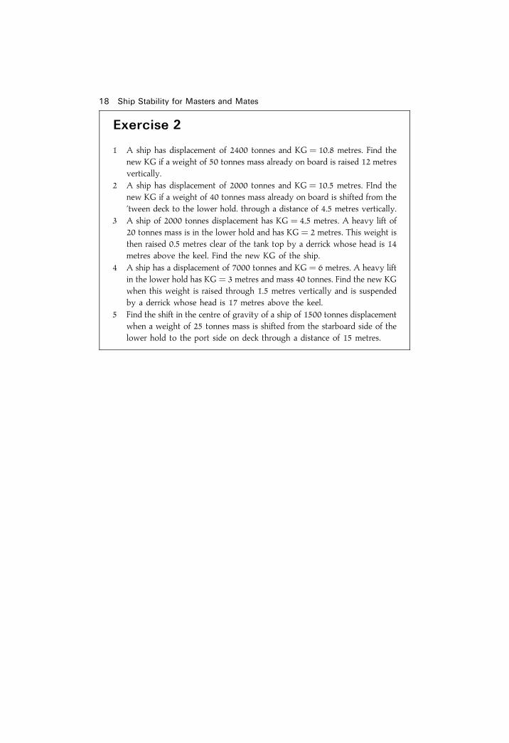
Exercise 2
1 A ship has displacement of 2400 tonnes and KG� 10.8 metres. Find thenew KG if a weight of 50 tonnes mass already on board is raised 12 metresvertically.
2 A ship has displacement of 2000 tonnes and KG� 10.5 metres. FInd thenew KG if a weight of 40 tonnes mass already on board is shifted from the'tween deck to the lower hold. through a distance of 4.5 metres vertically.
3 A ship of 2000 tonnes displacement has KG� 4.5 metres. A heavy lift of20 tonnes mass is in the lower hold and has KG� 2 metres. This weight isthen raised 0.5 metres clear of the tank top by a derrick whose head is 14metres above the keel. Find the new KG of the ship.
4 A ship has a displacement of 7000 tonnes and KG� 6 metres. A heavy liftin the lower hold has KG� 3 metres and mass 40 tonnes. Find the new KGwhen this weight is raised through 1.5 metres vertically and is suspendedby a derrick whose head is 17 metres above the keel.
5 Find the shift in the centre of gravity of a ship of 1500 tonnes displacementwhen a weight of 25 tonnes mass is shifted from the starboard side of thelower hold to the port side on deck through a distance of 15 metres.

Chapter 3
Density and speci®cgravityDensity is de®ned as `mass per unit volume'. e.g.
The mass density of FW � 1000 kg per cubic metre or 1.000 tonne/m3
The mass density of SW � 1025 kg per cubic metre or 1.025 tonne/m3
The speci®c gravity (SG) or relative density of a substance is de®ned asthe ratio of the weight of the substance to the weight of an equal volume offresh water.If a volume of one cubic metre is considered, then the SG or relative
density of a substance is the ratio of the density of the substance to thedensity of fresh water. i.e.
SG or relative density of a substance � Density of the substance
Density of fresh water
The density of FW � 1000 kg per cu. m
; SG of a substance � Density of the substance in kg per cu. m
1000
or
Density in kg per cu:m � 1000� SG
Example 1Find the relative density of salt water whose density is 1025 kg per cu. m
Relative density � Density of SW in kg per cu:m
1000
� 1025
1000
; relative density of salt water � 1:025
Example 2Find the density of a fuel oil whose relative density is 0.92
Density in kg per cu. m � 1000� SG� 1000� 0:92
; Density � 920 kg per cu. m
Example 3When a double-bottom tank is full of fresh water it holds 120 tonnes. Find howmany tonnes of oil of relative density 0.84 it will hold.
Relative density � Mass of oil
Mass of FW
or
Mass of oil � Mass of FW� relative density
� 120� 0:84 tonnes
Mass of oil � 100:8 tonnes
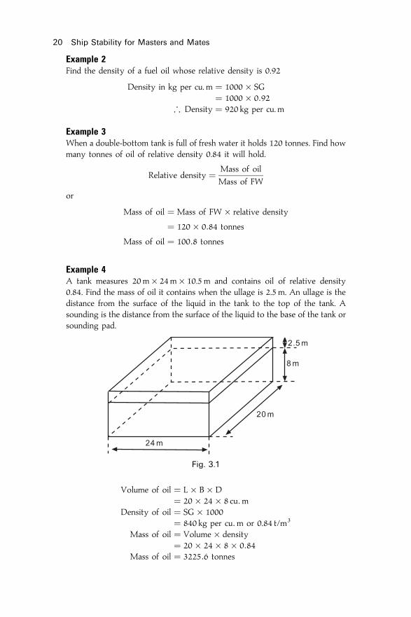
Example 4A tank measures 20m� 24m� 10.5 m and contains oil of relative density0.84. Find the mass of oil it contains when the ullage is 2.5 m. An ullage is thedistance from the surface of the liquid in the tank to the top of the tank. Asounding is the distance from the surface of the liquid to the base of the tank orsounding pad.
Volume of oil � L� B� D� 20� 24� 8 cu:m
Density of oil � SG� 1000� 840 kg per cu:m or 0.84 t/m3
Mass of oil � Volume� density� 20� 24� 8� 0:84
Mass of oil � 3225:6 tonnes
20 Ship Stability for Masters and Mates
Fig. 3.1

Example 5A tank will hold 153 tonnes when full of fresh water. Find how many tonnes ofoil of relative density 0.8 it will hold allowing 2% of the oil loaded forexpansion.
Mass of freshwater � 153 tonnes; Volume of the tank � 153m3
Volume of oil� 2% of volume of oil � Volume of the tankor 102% of volume of the oil � 153m3
; volume of the oil � 153� 100
102m3
� 150m3
Mass of the oil � Volume� Density� 150� 0:8 tonnes
Ans. � 120 tonnes
Density and speci®c gravity 21
Exercise 3
1 A tank holds 120 tonnes when full of fresh water. Find how many tonnes ofoil of relative density 0.84 it will hold, allowing 2% of the volume of thetank for expansion in the oil.
2 A tank when full will hold 130 tonnes of salt water. Find how many tonnesof oil relative density 0.909 it will hold, allowing 1% of the volume of thetank for expansion.
3 A tank measuring 8m� 6m� 7m is being ®lled with oil of relativedensity 0.9. Find how many tonnes of oil in the tank when the ullage is3 metres.
4 Oil of relative density 0.75 is run into a tank measuring 6m� 4m� 8muntil the ullage is 2 metres. Calculate the number of tonnes of oil the tankthen contains.
5 A tank will hold 100 tonnes when full of fresh water. Find how manytonnes of oil of relative density 0.85 may be loaded if 2% of the volume ofthe oil loaded is to be allowed for expansion.
6 A deep tank 10 metres long, 16 metres wide and 6 metres deep has acoaming 4 metres long, 4 metres wide and 25 cm deep. (Depth of tank doesnot include depth of coaming). How may tonnes of oil, of relative density0.92, can it hold if a space equal to 3% of the oil loaded is allowed forexpansion?

Chapter 4
Laws of ¯otationArchimedes' Principle states that when a body is wholly or partiallyimmersed in a ¯uid it appears to suffer a loss in mass equal to the massof the ¯uid it displaces.The mass density of fresh water is 1000 kg per cu. m. Therefore, when a
body is immersed in fresh water it will appear to suffer a loss in mass of1000 kg for every 1 cu. m of water it displaces.When a box measuring 1 cu. m and of 4000 kg mass is immersed in fresh
water it will appear to suffer a loss in mass of 1000 kg. If suspended from aspring balance the balance would indicate a mass of 3000 kg.
Since the actual mass of the box is not changed, there must be a forceacting vertically upwards to create the apparent loss of mass of 1000 kg.This force is called the force of buoyancy, and is considered to act verticallyupwards through a point called the centre of buoyancy. The centre ofbuoyancy is the centre of gravity of the underwater volume.Now consider the box shown in Figure 4.2(a) which also has a mass of
4000 kg, but has a volume of 8 cu. m. If totally immersed in fresh water itwill displace 8 cu. m of water, and since 8 cu. m of fresh water has a mass of
Fig. 4.1

8000 kg, there will be an upthrust or force of buoyancy causing an apparentloss of mass of 8000 kg. The resultant apparent loss of mass is 4000 kg.When released, the box will rise until a state of equilibrium is reached, i.e.when the buoyancy is equal to the mass of the box. To make the buoyancyproduce a loss of mass of 4000 kg the box must be displacing 4 cum ofwater. This will occur when the box is ¯oating with half its volumeimmersed, and the resultant force then acting on the box will be zero. Thisis shown in Figure 4.2(c).Now consider the box to be ¯oating in fresh water with half its volume
immersed as shown in Figure 4.2(c). If a mass of 1000 kg be loaded on deckas shown in Figure 4.3(a) the new mass of the body will be 5000 kg, andsince this exceeds the buoyancy by 1000 kg, it will move downwards.
The downwards motion will continue until buoyancy is equal to the massof the body. This will occur when the box is displacing 5 cu. m of water andthe buoyancy is 5000 kg, as shown in Figure 4.3(b).The conclusion which may be reached from the above is that for a body
to ¯oat at rest in still water, it must be displacing its own weight of waterand the centre of gravity must be vertically above or below the centre ofbuoyancy.
Laws of ¯otation 23
Fig. 4.2
Fig. 4.3

The variable immersion hydrometerThe variable immersion hydrometer is an instrument, based on the Law ofArchimedes, which is used to determine the density of liquids. The type ofhydrometer used to ®nd the density of the water in which a ship ¯oats isusually made of a non-corrosive material and consists of a weighted bulbwith a narrow rectangular stem which carries a scale for measuring densitiesbetween 1000 and 1025 kilograms per cubic metre, i.e. 1.000 and 1.025 t/m3.The position of the marks on the stem are found as follows. First let the
hydrometer, shown in Figure 4.4, ¯oat upright in fresh water at the mark X.Take the hydrometer out of the water and weigh it. Let the mass be Mx
kilograms. Now replace the hydrometer in fresh water and add lead shot inthe bulb until it ¯oats with the mark Y, at the upper end of the stem, in the
24 Ship Stability for Masters and Mates
Fig. 4.4

waterline. Weigh the hydrometer again and let its mass now be My
kilograms.The mass of water displaced by the stem between X and Y is therefore
equal to My ÿMx kilograms. Since 1000 kilograms of fresh water occupyone cubic metre, the volume of the stem between X and Y is equal toMy ÿMx
1000cu:m.
Let L represent the length of the stem between X and Y, and let `a'represent the cross-sectional area of the stem.
a � Volume
Length
� My ÿMx
1000 Lsqm
Now let the hydrometer ¯oat in water of density d kg/m3 with thewaterline `x' metres below Y.
Volume of water displaced � My
1000ÿ x a
� My
1000ÿ x
�My ÿMx
1000 L
��I�
But
Volume of water displaced � Mass of water displaced
Density of water displaced
� My
1000 d�II�
Equate (I) and (II) ;My
1000 d� My
1000ÿ x
�My ÿMx
1000 L
�or
d � My
My ÿ x
�My ÿMx
L
�
In this equation, My, Mx and L are known constants whilst d and x arevariables. Therefore, to mark the scale it is now only necessary to selectvarious values of d and to calculate the corresponding values of x.
Laws of ¯otation 25

Tonnes per Centimetre Immersion (TPC)The TPC for any draft is the mass which must be loaded or discharged tochange a ship's mean draft in salt water by one centimetre, where
TPC � water-plane area
100� density of water
; TPC � WPA
100� r
WPA is in m2.r is in t/m3.
Consider a ship ¯oating in salt water at the waterline WL as shown inFigure 4.5. Let `A' be the area of the water-plane in square metres.Now let a mass of `w' tonnes be loaded so that the mean draft is
increased by one centimetre. The ship then ¯oats at the waterline W1 L1.Since the draft has been increased by one centimetre, the mass loaded isequal to the TPC for this draft. Also, since an extra mass of water equal tothe mass loaded must be displaced, then the mass of water in the layerbetween WL and W1 L1 is also equal to the TPC.
Mass � Volume� Density
� A� 1
100� 1025
1000tonnes � 1:025A
100tonnes
; TPCsw � 1:025A
100� WPA
97:56: Also, TPCfw � WPA
100
TPC in dock waterNote. When a ship is ¯oating in dock water of a relative density other than1.025 the weight to be loaded or discharged to change the mean draft by 1centimetre (TPCdw) may be found from the TPC in salt water (TPCsw) bysimple proportion as follows:
TPCdw
TPCsw� relative density of dock water �RDdw�
relative density of salt water �RDsw�or
TPCdw � RDdw
1:025� TPCsw
26 Ship Stability for Masters and Mates
Fig. 4.5

Reserve buoyancyIt has already been shown that a ¯oating vessel must displace its ownweight of water. Therefore, it is the submerged portion of a ¯oating vesselwhich provides the buoyancy. The volume of the enclosed spaces abovethe waterline are not providing buoyancy but are being held in reserve. Ifextra weights are loaded to increase the displacement, these spaces abovethe waterline are there to provide the extra buoyancy required. Thus, reservebuoyancy may be de®ned as the volume of the enclosed spaces above thewaterline. It may be expressed as a volume or as a percentage of the totalvolume of the vessel.
Example 1A box-shaped vessel 105m long, 30m beam, and 20m deep, is ¯oating uprightin fresh water. If the displacement is 19 500 tonnes, ®nd the volume of reservebuoyancy.
Volume of water displaced � Mass
Density� 19 500 cu:m
Volume of vessel � 105� 30� 20 cu:m
� 63 000 cu:m
Reserve buoyancy � Volume of vessel N volume of water displaced
Ans. Reserve buoyancy � 43 500 cu. m
Example 2A box-shaped barge 16m� 6m� 5m is ¯oating alongside a ship in freshwater at a mean draft of 3.5 m. The barge is to be lifted out of the water andloaded on to the ship with a heavy-lift derrick. Find the load in tonnes borne bythe purchase when the draft of the barge has been reduced to 2 metres.Note. By Archimedes' Principle the barge suffers a loss in mass equal to themass of water displaced. The mass borne by the purchase will be the differencebetween the actual mass of the barge and the mass of water displaced at anydraft, or the difference between the mass of water originally displaced by thebarge and the new mass of water displaced.
Mass of the barge � Original mass of water displaced� Volume� density� 16� 6� 3:5� 1 tonnes
Mass of water displace at 2m draft � 16� 6� 2� 1 tonnes; Load borne by the purchase � 16� 6� 1� �3:5ÿ 2� tonnes
Ans. � 144 tonnes
Example 3A cylindrical drum 1.5 m long and 60 cm in diameter has mass 20 kg whenempty. Find its draft in water of density 1024 kg per cu. m if it contains 200
Laws of ¯otation 27

litres of paraf®n of relative density 0.6, and is ¯oating with its axis perpen-dicular to the waterline (Figure 4.6).Note. The drum must displace a mass of water equal to the mass of the drumplus the mass of the paraf®n.
Density of the paraffin � SG� 1000 kg per cu. m
� 600 kg per cu. m
Mass of the paraffin � Volume� density � 0:2� 600 kg
� 120 kg
Mass of the drum � 20 kg
Total mass � 140 kg
Therefore the drum must displace 140 kg of water.
Volume of water displaced � Mass
Density� 140
1024cu. m
Volume of water displaced � 0:137 cu. m
Let d� draft, and r� radius of the drum, where r� 60
2� 30 cm � 0:3m.
28 Ship Stability for Masters and Mates
Fig. 4.6

Volume of water displaced (V) � pr2 dor
d � V
pr2
� 0:13722
7� 0:3� 0:3
m
� 0:484mAns. Draft � 0:484m
Homogeneous logs of rectangular sectionThe draft at which a rectangular homogeneous log will ¯oat may be foundas follows:
Mass of log � Volume�density� L� B� D� SG of log�1000 kg
Mass of water displaced � Volume�density� L� B� d� SG of water�1000 kg
But Mass of water displaced � Mass of log; L� B� d� SG of water� 1000 � L� B� D� SG of log� 1000
ord� SG of water � D� SG of log
Draft
Depth� SG of log
SG of wateror
relative density of log
relative density of water
Example 4Find the distance between the centres of gravity and buoyancy of a rectangularlog 1.2 m wide, 0.6 m deep, and of relative density 0.8 when ¯oating in freshwater with two of its sides parallel to the waterline.
If BM is equal tob2
12 ddetermine if this log will ¯oat with two of its sides
parallel to the waterline.
Note. The centre of gravity of a homogeneous log is at its geometrical centre.See Figure 4.7
Draft
Depth� Relative density of log
Relative density of water
Draft � 0:6� 0:8
1
Draft � 0:48m
KB � 0:24m
KG � 0:30m
9>>=>>; see Figure 4.8
Ans. BG � 0:06m
Laws of ¯otation 29

�� � ��
��� �� ����
��� ���� ��� �
�� � ���� � ����� �
�� � ��� �� � ����� �
��� � ����� �
�� � ���� �
������������� ��� � �� ����� �� ���� ����������� ��� �� �� �� ��� ������� ���!"����������#� �� ���� $� � ���� ��� �% ��� ����� & ���� �� ��� � �� ����!
�� ���� ������� � � ������� ��� �����
���� ���
���� ���

Laws of ¯otation 31
Exercise 4
1 A drum of mass 14 kg when empty, is 75 cm long, and 60 cm in diameter.Find its draft in salt water if it contains 200 litres of paraf®n of relativedensity 0.63.
2 A cube of wood of relative density 0.81 has sides 30 cm long. If a mass of2 kg is placed on the top of the cube with its centre of gravity verticallyover that of the cube, ®nd the draft in salt water.
3 A rectangular tank (3m� 1.2m� 0.6 m) has no lid and is ¯oating in freshwater at a draft of 15 cm. Calculate the minimum amount of fresh waterwhich must be poured into the tank to sink it.
4 A cylindrical salvage buoy is 5 metres long, 2.4 metres in diameter, and¯oats on an even keel in salt water with its axis in the water-plane. Findthe upthrust which this buoy will produce when fully immersed.
5 A homogeneous log of rectangular cross-section is 30 cm wide and 25 cmdeep. The log ¯oats at a draft of 17 cm. Find the reserve buoyancy and thedistance between the centre of buoyancy and the centre of gravity.
6 A homogeneous log of rectangular cross-section is 5m. long, 60 cm wide,40 cm deep, and ¯oats in fresh water at a draft of 30 cm. Find the mass ofthe log and its relative density.
7 A homogeneous log is 3 m long, 60 cm wide, 60 cm deep, and has relativedensity 0.9. Find the distance between the centres of buoyancy andgravity when the log is ¯oating in fresh water.
8 A log of square section is 5 m� 1m� 1m. The relative density of the logis 0.51 and it ¯oats half submerged in dock water. Find the relative densityof the dock water.
9 A box-shaped vessel 20m� 6m� 2.5m ¯oats at a draft of 1.5 m in waterof density 1013 kg per cu. m. Find the displacement in tonnes, and theheight of the centre of buoyancy above the keel.
10 An empty cylindrical drum 1 metre long and 0.6m. in diameter has mass20 kg. Find the mass which must be placed in it so that it will ¯oat withhalf of its volume immersed in (a) salt water, and (b) fresh water.
11 A lifeboat, when fully laden, displaces 7.2 tonnes. Its dimensions are7.5 m� 2.5m� 1m, and its block coef®cient 0.6. Find the percentage ofits volume under water when ¯oating in fresh water.
12 A homogeneous log of relative density 0.81 is 3 metres long, 0.5 metressquare cross-section, and is ¯oating in fresh water. Find the displacementof the log, and the distance between the centres of gravity andbuoyancy.
13 A box-shaped barge 55m� 10m� 6m. is ¯oating in fresh water onan even keel at 1.5 m draft. If 1800 tonnes of cargo is now loaded,®nd the difference in the height of the centre of buoyancy above thekeel.
14 A box-shaped barge 75m� 6m� 4m displaces 180 tonnes when light. If

32 Ship Stability for Masters and Mates
360 tonnes of iron are loaded while the barge is ¯oating in fresh water,®nd her ®nal draft and reserve buoyancy.
15 A drum 60 cm in diameter and 1 metre long has mass 30 kg when empty.If this drum is ®lled with oil of relative density 0.8, and is ¯oating in freshwater, ®nd the percentage reserve buoyancy.

Chapter 5
Effect of density ondraft anddisplacement
Effect of change of density when the displacementis constantWhen a ship moves from water of one density to water of another density,without there being a change in her mass, the draft will change. This willhappen because the ship must displace the same mass of water in each case.Since the density of the water has changed, the volume of water displacedmust also change. This can be seen from the formula:
Mass � Volume� Density
If the density of the water increases, then the volume of water displacedmust decrease to keep the mass of water displaced constant, and vice versa.
The effect on box-shaped vessels
New mass of water displaced � Old mass of water displaced
; New volume� new density � Old volume�Old densityNew volume
Old volume� Old density
New densityBut volume � L� B� draft
;L� B� New draft
L� B�Old draft� Old density
New densityor
New draft
Old draft� Old density
New density
Example 1A box-shaped vessel ¯oats at a mean draft of 2.1 metres, in dock water ofdensity 1020 kg per cu. m. Find the mean draft for the same mass displacement

in salt water of density 1025 kg per cubic metre.
New draft
Old draft� Old density
New density
New draft � Old density
New density�Old draft
� 1020
1025� 2:1m
� 2:09m
Ans. New draft � 2:09m
Example 2A box-shaped vessel ¯oats upright on an even keel as shown in fresh water ofdensity 1000 kg per cu. m, and the centre of buoyancy is 0.50m above the keel.Find the height of the centre of buoyancy above the keel when the vessel is¯oating in salt water of density 1025 kg per cubic metre.Note. The centre of buoyancy is the geometric centre of the underwatervolume and for a box-shaped vessel must be at half draft, i.e. KB� 1
2 draft.
In Fresh Water
KB � 0:5m, and since KB � 12 draft, then draft � 1m
In Salt Water
New draft
Old draft� Old density
New density
New draft � Old draft� Old density
New density
� 1� 1000
1025
New draft � 0:976m
New KB � 12 new draft
Ans. New KB � 0:488m, say 0.49m.
34 Ship Stability for Masters and Mates
Fig. 5.1

The effect on ship-shaped vesselsIt has already been shown that when the density of the water in which avessel ¯oats is changed the draft will change, but the mass of water in kg ortonnes displaced will be unchanged. i.e.
New displacement � Old displacementor
New volume� new density � Old volume� old density
;New volume
Old volume� Old density
New density
With ship-shapes this formula should not be simpli®ed further as it was inthe case of a box-shape because the underwater volume is not rectangular.To ®nd the change in draft of a ship-shape due to change of density aquantity known as the `Fresh Water Allowance' must be known.The Fresh Water Allowance is the number of millimetres by which the
mean draft changes when a ship passes from salt water to fresh water,or vice versa, whilst ¯oating at the loaded draft. It is found by theformula:
FWA (in mm) � Displacement (in tonnes)
4� TPC
The proof of this formula is as follows:
To show that FWA (in mm) � Displacement (in tonnes)
4� TPC
Consider the ship shown in Figure 5.2 to be ¯oating at the load Summerdraft in salt water at the waterline WL. Let V be the volume of salt waterdisplaced at this draft.Now let W1L1 be the waterline for the ship when displacing the same
mass of fresh water. Also, let `v' be the extra volume of water displaced infresh water.
Effect of density on draft and displacement 35
Fig. 5.2

The total volume of fresh water displaced is then V� v.
Mass � Volume� density
; Mass of SW displaced � 1025V
and mass of FW displaced � 1000 �V� v�but mass of FW displaced � mass of SW displaced
; 1000 �V� v� � 1025V
1000 V� 1000 v � 1025V
1000 v � 25V
v � V=40
Now let w be the mass of salt water in volume v, in tonnes and let W bethe mass of salt water in volume V, in tonnes.
; w � W=40
but w � FWA
10� TPC
FWA
10� TPC � W=40
or
FWA � W
4� TPCmm
whereW � Loaded salt water displacement in tonnes
Figure 5.3 shows a ship's load line marks. The centre of the disc is at adistance below the deck line equal to the ship's Statutory Freeboard. Then540mm forward of the disc is a vertical line 25mm thick, with horizontallines measuring 230� 25mm on each side of it. The upper edge of theone marked `S' is in line with the horizontal line through the disc andindicates the draft to which the ship may be loaded when ¯oating in saltwater in a Summer Zone. Above this line and pointing aft is another linemarked `F', the upper edge of which indicates the draft to which the shipmay be loaded when ¯oating in fresh water in a Summer Zone. If loadedto this draft in fresh water the ship will automatically rise to `S' when shepasses into salt water. The perpendicular distance in millimetres betweenthe upper edges of these two lines is therefore the ship's Fresh WaterAllowance.When the ship is loading in dock water which is of a density between
these two limits `S' may be submerged such a distance that she willautomatically rise to `S' when the open sea and salt water is reached. The
36 Ship Stability for Masters and Mates

�������� ����� �� ��� � ��������� ������ ��� ���� ���� ����� ��� ������� �� �������� ������ ���������� �� ��������
��� � � ��� ���� ����� ����������� ��� � ������ �� ��� ���� �����
�������
!� ��� "#$%� ���"#$%� "###
��
���� ����� �������� � !� �"#$%� ����$%
������� � ���� �� ������� �� ���� ����� �� ������ "#"# �� ��� ����& !� � "%#��&!��� ��� ������ �� ����� �� �������� ���� �����&
������ �� ����� �� �� �� �� ��� ������ ��
��� ���
��� ���

��� � � ��� ���� � � ��� � �������� ��
����
���� ����� ����
��
� � ���� ��
��
� � ����
���� � ��� ���� ��� ���� �� ����� ���� � ��
������� �� ��� �� �!��� � � "#��� $!� � �!�% ���� !� ������ ���� % � �#� ������ &������ �'(� �� �!��� ��� �!�� ��� !� ��� "#��� �!�� ����� � ��� ���� ��� �! ! � �� �� � �� ��!)� ��� ���� ��� �! ��� �!� �� ����!� �#�� �! � �� ! ��� �� �!���� �� ��� ��� �� �! �� �� ��� �! ��� �!��� ��� � ���� ���� ������ ���� ��� �� !�)�!#��� ������ �! ! � �� �� � !#�� # ��� ��� �!�� ��� !� ��� *"+ �!�� ��� ! ���� ���� �!#�� �� ���� ��!)� ��� ���� �������!� �� �� ��� # � ��� !� ��� ��� ����� �������� ��� *"+ �!�� � ��� ��� ������� ��� �� ���� ����%� ��� ��� +� � ��� �#�� �� �� ����� �� ���� �! � ��� �! ��� *"+ �!�� ��� � �!�% ���� � , ������! *"+ ��� �� �#��� �� ������
�
���� ����� ���
��
� � &���� ��
��
� � ����
� �!��� �� ���� � � ��� �-#� �� � ����� ! �� ��
�� �� ! �! �!�� � ,� ���� � � ���� �'(
� ��� ��
���� (� ! �! �!�� � ��� �!��
������ �� ����� �� �� ������� ���� ��� ����� �������"�!#�� ��� ������ !� ��� ���� � ����� � ��� .!��� �� ����� ����!#���� ��� ���� � �� � ���� ��� ��� ���� !� ���� ��� ����� �#�� ��)�
�� ���� ������� � � ������� ��� �����
���� ���

changed. The change in the mass of water displaced may have beenbrought about by bunkers and stores being loaded or consumed during asea passage, or by cargo being loaded or discharged.In all cases:
New volume of water displaced � Old volume of water displaced
orNew displacement
New density� Old displacement
Old density
orNew displacement
Old displacement� New density
Old density
Example 1A ship displaces 7000 tonnes whilst ¯oating in fresh water. Find the displace-ment of the ship when ¯oating at the same draft in water of density 1015 kgper cubic metre, i.e. 1.015 t/m3.
New displacement
Old displacement� New density
Old density
New displacement � Old displacement� New density
Old density
� 7000� 1015
1000
Ans. New displacement � 7105 tonnes
Example 2A ship of 6400 tonnes displacement is ¯oating in salt water. The ship has toproceed to a berth where the density of the water is 1008 kg per cu. m. Findhow much cargo must be discharged if she is to remain at the salt water draft.
New displacement
Old displacement� New density
Old density
or
New displacement � Old displacement� New density
Old density
� 6400� 1008
1025
New displacement � 6293:9 tonnes
Old displacement � 6400:0 tonnes
Ans. Cargo to discharge � 106:1 tonnes
Example 3A ship 120m� 17m� 10m has a block coef®cient 0.800 and is ¯oating at theload Summer draft of 7.2 metres in fresh water. Find how much more cargo can
Effect of density on draft and displacement 39
�� ������ �� ���� �� ��� �� ����� � ��� ������
��� � �������� � �� �� ������ �� � ��� ��
� ���� ��� ���� ������ ���� �����
��� � �������� � �� ��� �����
��� � ��������
��� � ��������� ��� ��� ��
��� ��� ��
��� � �������� � ��� � ��������� ��� ��� ��
��� ��� ��
� ��� ���� ����
����
��� � �������� � �� ��� �����
��� � �������� � �� ��� �����
���� ��� � �� ���� � �!� �����
����� "� ������ ��#�� ��� �� �������� � ��� �$��$� "%� ��� &'(�
�� ���� ������� � � ������� ��� �����

Effect of density on draft and displacement 41
Exercise 5
Density and draft
1 A ship displaces 7500 cu. m of water of density 1000 kg per cu. m. Findthe displacement in tonnes when the ship is ¯oating at the same draft inwater of density 1015 kg per cu. m.
2 When ¯oating in fresh water at a draft of 6.5 m a ship displaces 4288tonnes. Find the displacement when the ship is ¯oating at the same draftin water of density 1015 kg per cu. m.
3 A box-shaped vessel 24m� 6m� 3m displaces 150 tonnes of water.Find the draft when the vessel is ¯oating in salt water.
4 A box-shaped vessel draws 7.5 m in dock water of density 1006 kg percu. m. Find the draft in salt water of density 1025 kg per cu. m.
5 The KB of a rectangular block which is ¯oating in fresh water is 50 cm.Find the KB in salt water.
6 A ship is lying at the mouth of a river in water of density 1024 kg percu. m and the displacement is 12 000 tonnes. The ship is to proceed upriver and to berth in dock water of density 1008 kg per cu. m with thesame draft as at present. Find how much cargo must be discharged.
7 A ship arrives at the mouth of a river in water of density 1016 kg percu. m with a freeboard of 'S' m. She then discharges 150 tonnes of cargo,and proceeds up river to a second port, consuming 14 tonnes of bunkers.When she arrives at the second port the freeboard is again `S' m., thedensity of the water being 1004 kg per cu. m. Find the ship's displacementon arrival at the second port.
8 A ship loads in fresh water to her salt water marks and proceeds along ariver to a second port consuming 20 tonnes of bunkers. At the secondport, where the density is 1016 kg per cu. m, after 120 tonnes of cargohave been loaded, the ship is again at the load salt water marks. Find theship's load displacement in salt water.
The TPC and FWA etc.
9 A ship's draft is 6.40 metres forward, and 6.60 metres aft.FWA� 180mm. Density of the dock water is 1010 kg per cu. m. If theload mean draft in salt water is 6.7 metres, ®nd the ®nal drafts F and A indock water if this ship is to be loaded down to her marks and trimmed0.15 metres by the stern. (Centre of ¯otation is amidships).
10 A ship ¯oating in dock water of density 1005 kg per cu. m has the loweredge of her Summer load line in the waterline to starboard and 50mmabove the waterline to port. FWA� 175mm and TPC� 12 tonnes. Findthe amount of cargo which can yet be loaded in order to bring the ship tothe load draft in salt water.
11 A ship is ¯oating at 8 metres mean draft in dock water of relative density1.01. TPC� 15 tonnes, and FWA� 150mm. The maximum permissibledraft in salt water is 8.1 m. Find the amount of cargo yet to load.

42 Ship Stability for Masters and Mates
12 A ship's light displacement is 3450 tonnes and she has on board 800tonnes of bunkers. She loads 7250 tonnes of cargo, 250 tonnes of bunkers,and 125 tonnes of fresh water. The ship is then found to be 75mm fromthe load draft. TPC� 12 tonnes. Find the ship's deadweight and loaddisplacement.
13 A ship has a load displacement of 5400 tonnes, TPC� 30 tonnes. If sheloads to the Summer load line in dock water of density 1010 kg per cu. m,®nd the change in draft on entering salt water of density 1025 kg percu. m.
14 A ship's FWA is 160mm, and she is ¯oating in dock water of density1012 kg per cu. m. Find the change in draft when she passes from dockwater to salt water.

Chapter 6
Transverse staticalstabilityRecapitulation1. The centre of gravity of a body `G' is the point through which the force
of gravity is considered to act vertically downwards with a force equalto the weight of the body. KG is VCG of the ship.
2. The centre of buoyancy `B' is the point through which the force ofbuoyancy is considered to act vertically upwards with a force equal tothe weight of water displaced. It is the centre of gravity of theunderwater volume. KB is VCB of the ship.
3. To ¯oat at rest in still water, a vessel must displace her own weight ofwater, and the centre of gravity must be in the same vertical line as thecentre of buoyancy.
4. KM� KB� BM. Also KM� KG�GM.
De®nitions1. Heel. A ship is said to be heeled when she is inclined by an external force.
For example, when the ship is inclined by the action of the waves or wind.2 List. A ship is said to be listed when she is inclined by forces within theship. For example, when the ship is inclined by shifting a weighttransversely within the ship. This is a ®xed angle of heel.
The metacentreConsider a ship ¯oating upright in still water as shown in Figure 6.1(a). Thecentres of gravity and buoyancy are at G and B respectively. Figure 6.1(c)shows the righting couple. GZ is the righting lever.Now let the ship be inclined by an external force to a small angle �y� as
shown in Figure 6.1(b). Since there has been no change in the distribution ofweights the centre of gravity will remain at G and the weight of the ship(W) can be considered to act vertically downwards through this point.When heeled, the wedge of buoyancy WOW1 is brought out of the water
and an equal wedge LOL1 becomes immersed. In this way a wedge ofbuoyancy having its centre of gravity at g is transferred to a position with its

centre of gravity at g1. The centre of buoyancy, being the centre of gravity
of the underwater volume, must shift from B to the new position B1, such
that BB1 is parallel to gg1, and BB1 � v� gg1V
where v is the volume of the
transferred wedge, and V is the ship's volume of displacement.The verticals through the centres of buoyancy at two consecutive angles
of heel intersect at a point called the metacentre. For angles of heel up toabout 15� the vertical through the centre of buoyancy may be consideredto cut the centre line at a ®xed point called the initial metacentre (M inFigure 6.1(b)). The height of the initial metacentre above the keel (KM)depends upon a ship's underwater form. Figure 6.2 shows a typical curve ofKM's for a ship plotted against draft.The vertical distance between G and M is referred to as the metacentric
height. If G is below M the ship is said to have positive metacentric height,and if G is above M the metacentric height is said to be negative.
Equilibrium
Stable equilibriumA ship is said to be in stable equilibrium if, when inclined, she tends toreturn to the initial position. For this to occur the centre of gravity must be
44 Ship Stability for Masters and Mates
Righting couple where b�w
Fig. 6.1. Stable equilibrium

below the metacentre, that is, the ship must have positive initial metacentricheight. Figure 6.1(a) shows a ship in the upright position having a positiveGM. Figure 6.1(b) shows the same ship inclined to a small angle. Theposition of G remains unaffected by the heel and the force of gravity isconsidered to act vertically downwards through this point. The centre ofbuoyancy moves out to the low side from B to B1 to take up the new centreof gravity of the underwater volume, and the force of buoyancy isconsidered to act vertically upwards through B1 and the metacentre M.If moments are taken about G there is a moment to return the ship to theupright. This moment is referred to as the Moment of Statical Stability and isequal to the product of the force 'W' and the length of the lever GZ. i.e.
Moment of Statical Stability �W � GZ tonnes-metres.
The lever GZ is referred to as the righting lever and is the perpendiculardistance between the centre of gravity and the vertical through the centreof buoyancy.At a small angle of heel (less than 15�):
GZ � GM� sin y and Moment of Statical Stability � W� GM� sin y
Transverse statical stability 45
Fig. 6.2

Unstable equilibriumWhen a ship which is inclined to a small angle tends to heel over stillfurther, she is said to be in unstable equilibrium. For this to occur the shipmust have a negative GM. Note how G is above M.Figure 6.3(a) shows a ship in unstable equilibrium which has been inclined
to a small angle. The moment of statical stability, W�GZ, is clearly acapsizing moment which will tend to heel the ship still further.
Note. A ship having a very small negative initial metacentric height GMneed not necessarily capsize. This point will be examined and explainedlater. This situation produces an angle of loll.
Neutral equilibriumWhen G coincides with M as shown in Figure 6.4(a), the ship is said to be inneutral equilibrium, and if inclined to a small angle she will tend to remain
46 Ship Stability for Masters and Mates
Fig. 6.3. Unstable equilibrium.
Fig. 6.4. Neutral equilibrium.

at that angle of heel until another external force is applied. The ship haszero GM. Note that KG� KM.
Moment of Statical Stability � W� GZ, but in this case GZ � 0
; Moment of Statical Stability � 0 see Figure 6.4(b)
Therefore there is no moment to bring the ship back to the upright or toheel her over still further. The ship will move vertically up and down in thewater at the ®xed angle of heel until further external or internal forces areapplied.
Correcting unstable and neutral equilibriumWhen a ship in unstable or neutral equilibrium is to be made stable, thceffective centre of gravity of the ship should be lowered. To do this one ormore of the following methods may be employed:
1. weights already in the ship may be lowered,2. weights may be loaded below the centre of gravity of the ship,3. weights may be discharged from positions above the centre of gravity,
or4. free surfaces within the ship may be removed.
The explanation of this last method will be found in Chapter 7.
Stiff and tender shipsThe time period of a ship is the time taken by the ship to roll from one sideto the other and back again to the initial position.When a ship has a comparatively large GM, for example 2m to 3m, the
righting moments at small angles of heel will also be comparatively large. Itwill thus require larger moments to incline the ship. When inclined she willtend to return more quickly to the initial position. The result is that the shipwill have a comparatively short time period, and will roll quickly ± andperhaps violently ± from side to side. A ship in this condition is said to be`stiff', and such a condition is not desirable. The time period could be as lowas 8 seconds. The effective centre of gravity of the ship should be raisedwithin that ship.When the GM is comparatively small, for example 0.16m to 0.20m the
righting moments at small angles of heel will also be small. The ship willthus be much easier to incline and will not tend to return so quickly to theinitial position. The time period will be comparatively long and a ship, forexample 30 to 35 seconds, in this condition is said to be `tender'. As before,this condition is not desirable and steps should be taken to increase the GMby lowering the effective centre of gravity of the ship.The of®cer responsible for loading a ship should aim at a happy medium
between these two conditions whereby the ship is neither too stiff nor tootender. A time period of 20 to 25 seconds would generally be acceptablefor those on board a ship at sea.
Transverse statical stability 47
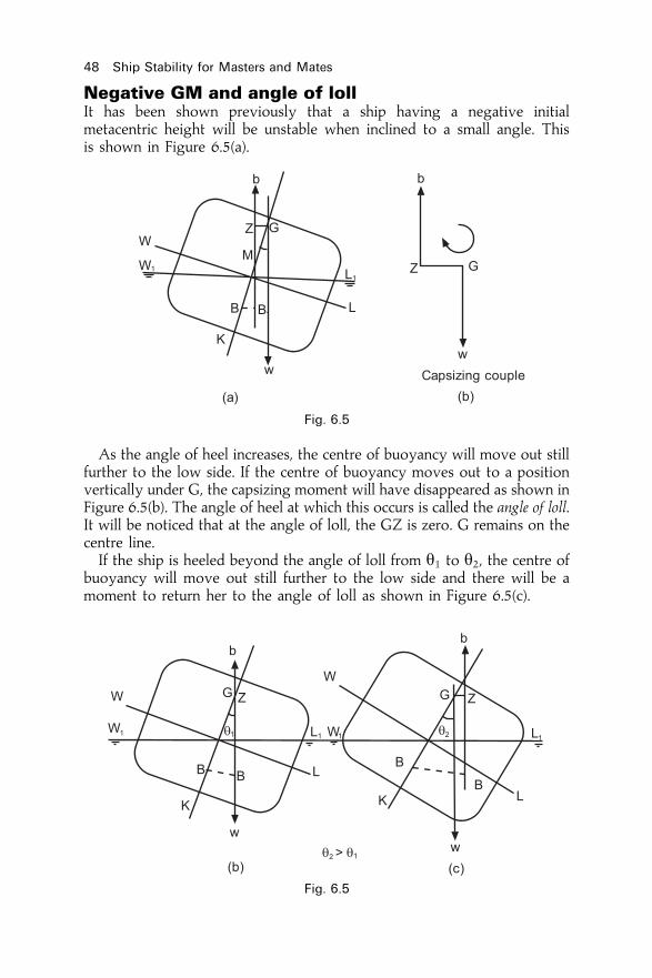
Negative GM and angle of lollIt has been shown previously that a ship having a negative initialmetacentric height will be unstable when inclined to a small angle. Thisis shown in Figure 6.5(a).
As the angle of heel increases, the centre of buoyancy will move out stillfurther to the low side. If the centre of buoyancy moves out to a positionvertically under G, the capsizing moment will have disappeared as shown inFigure 6.5(b). The angle of heel at which this occurs is called the angle of loll.It will be noticed that at the angle of loll, the GZ is zero. G remains on thecentre line.If the ship is heeled beyond the angle of loll from y1 to y2, the centre of
buoyancy will move out still further to the low side and there will be amoment to return her to the angle of loll as shown in Figure 6.5(c).
48 Ship Stability for Masters and Mates
Fig. 6.5
Fig. 6.5

From this it can be seen that the ship will oscillate about the angle of lollinstead of about the vertical. If the centre of buoyancy does not move outfar enough to get vertically under G, the ship will capsize.The angle of loll will be to port or starboard and back to port depending
on external forces such as wind and waves. One minute it may ¯op over to3� P and then suddenly ¯op over to 3� S.There is always the danger that G will rise above M and create a
situation of unstable equilibrium. This will cause capsizing of the ship.
The GM valueGM is crucial to ship stability. The table below shows typical workingvalues for GM for several ship-types all at fully-loaded drafts.
Ship type GM at fully-loaded condition
General cargo ships 0.30±0.50mOil tankers to VLCCs 0.30±1.00mContainer ships 1.50m approx.Ro-Ro vessels 1.50m approx.Bulk ore carriers 2±3m
At drafts below the fully-loaded draft, due to KM tending to be larger invalue it will be found that corresponding GM values will be higher thanthose listed in the table above. For all conditions of loading the D.Tpstipulate that the GM must never be less than 0.15m.
Transverse statical stability 49
Exercise 6
1 De®ne the terms `heel', `list', `initial metacentre' and `initial metacentricheight'.
2 Sketch transverse sections through a ship, showing the positions of thecentre of gravity, centre of buoyancy, and initial metacentre, when the shipis in (a) Stable equilibrium, (b) Unstable equilibrium, and (c) Neutralequilibrium.
3 Explain what is meant by a ship being (a) tender and, (b) stiff;4 With the aid of suitable sketches, explain what is meant by `angle of loll'.5 A ship of 10 000 t displacement has an initial metacentric height of 1.5 m.
What is the moment of statical stability when the ship is heeled 10 degrees?

Chapter 7
Effect of free surfaceof liquids on stabilityWhen a tank is completely ®lled with a liquid, the liquid cannot movewithin the tank when the ship heels. For this reason, as far as stability isconcerned, the liquid may be considered a static weight having its centre ofgravity at the centre of gravity of the liquid within the tank.Figure 7.1(a) shows a ship with a double-bottom tank ®lled with a liquid
having its centre of gravity at g. The effect when the ship is heeled to asmall angle y is shown in Figure 7.1(b). No weights have been movedwithin the ship, therefore the position of G is not affected. The centre ofbuoyancy will move out to the low side indicated by BB1.
Moment of statical stability � W� GZ� W� GM� sin y
Now consider the same ship ¯oating at the same draft and having thesame KG, but increase the depth of the tank so that the liquid now onlypartially ®lls it as shown in Figures 7.1(c) and 7.1(d).
Fig. 7.1

When the ship heels, as shown in Figure 7.2, the liquid ¯ows to the lowside of the tank such that its centre of gravity shifts from g to g1. This willcause the ship's centre of gravity to shift from G to G1, parallel to gg1.
Moment of statical stability � W� G1Z1
� W� GvZv
� W� GvM� sin y
This indicates that the effect of the free surface is to reduce the effectivemetacentric height from GM to GvM. GGv is therefore the virtual loss ofGM due to the free surface. Any loss in GM is a loss in stability.If free surface be created in a ship with a small initial metacentric height,
the virtual loss of GM due to the free surface may result in a negativemetacentric height. This would cause the ship to take up an angle of lollwhich may be dangerous and in any case is undesirable. This should beborne in mind when considering whether or not to run water ballast intotanks to correct an angle of loll, or to increase the GM. Until the tank is fullthere will be a virtual loss of GM due to the free surface effect of the liquid.It should also be noted from Figure 7.2 that even though the distance GG1
is fairly small it produces a relatively large virtual loss in GM (GGv).
Correcting an angle of lollIf a ship takes up an angle of loll due to a very small negative GM it shouldbe corrected as soon as possible. GM may be, for example ÿ0:05 toÿ0:10m, well below the D.Tp. minimum stipulation of 0.15m.First make sure that the heel is due to a negative GM and not due to
uneven distribution of the weights on board. For example, when bunkersare burned from one side of a divided double bottom tank it will obviouslycause G to move to G1, away from the centre of gravity of the burnedbunkers, and will result in the ship listing as shown in Figure 7.3.
Effect of free surface of liquids on stability 51
Fig. 7.1

Having satis®ed oneself that the weights within the ship are uniformlydistributed, one can assume that the list is probably due to a very smallnegative GM. To correct this it will be necessary to lower the position ofthe effective centre of gravity suf®ciently to bring it below the initialmetacentre. Any slack tanks should be topped up to eliminate the virtualrise of G due to free surface effect. If there are any weights which can belowered within the ship, they should be lowered. For example, derricks maybe lowered if any are topped; oil in deep tanks may be transferred to doublebottom tanks, etc.
52 Ship Stability for Masters and Mates
Fig. 7.2
Fig. 7.3

Assume now that all the above action possible has been taken and thatthe ship is still at an angle of loll. Assume also that there are double bottomtanks which are empty. Should they be ®lled, and if so, which ones ®rst?Before answering these questions consider the effect on stability during
the ®lling operation. Free surfaces will be created as soon as liquid enters anempty tank. This will give a virtual rise of G which in turn will lead to anincreased negative GM and an increased angle of loll. Therefore, if it isdecided that it is safe to use the tanks, those which have the smallest areacan be ®lled ®rst so that the increase in list is cut to a minimum. Tanksshould be ®lled one at a time.Next, assume that it is decided to start by ®lling a tank which is divided
at the centre line. Which side is to be ®lled ®rst? If the high side is ®lled ®rstthe ship will start to right herself but will then roll suddenly over to take upa larger angle of loll on the other side, or perhaps even capsize. Nowconsider ®lling the low side ®rst. Weight will be added low down in thevessel and G will thus be lowered, but the added weight will also cause Gto move out of the centre line to the low side, increasing the list. Freesurface is also being created and this will give a virtual rise in G, thuscausing a loss in GM, which will increase the list still further.
Figure 7.4(a) shows a ship at an angle of loll with the double bottomtanks empty and in Figure 7.4(b) some water has been run into the low side.The shift of the centre of gravity from G to Gv is the virtual rise of G dueto the free surface, and the shift from Gv to G1 is due to the weight of theadded water.It can be seen from the ®gure that the net result is a moment to list the
ship over still further, but the increase in list is a gradual and controlledincrease. When more water is now run into the tank the centre of gravity ofthe ship will gradually move downwards and the list will start to decrease.
Effect of free surface of liquids on stability 53
Fig. 7.4
As the list decreases, water may be run into the other side of the tank. Thewater will then be running in much more quickly, causing G to movedownwards more quickly. The ship cannot roll suddenly over to the otherside as there is more water in the low side than in the high side. If suf®cientweight of water is loaded to bring G on the centre line below M, the shipshould complete the operation upright.To summarize:
(a) Check that the list is due to a very small negative GM, for exampleÿ0:05 to ÿ0:10m.
(b) Top up any slack tanks and lower weights within the ship if possible.(c) If the ship is still listed and it is decided to ®ll double-bottom tanks,
start by ®lling the low side of a tank which is adequately sub-divided.(d) The list is bound to be increased in the initial stages.(e) Never start by ®lling tanks on the high side ®rst.(f) Always calculate the effects ®rst before authorizing action to be taken to
ballast any tanks.
54 Ship Stability for Masters and Mates
Exercise 7
1 With the aid of suitable sketches, show the effect of slack tanks on a ship'sstability.
2 A ship leaves port upright with a full cargo of timber, and with timber ondeck. During the voyage, bunkers, stores and fresh water are consumedevenly from each side. If the ship arrives at her destination with a list,explain the probable cause of the list and how this should be remedied.
3 A ship loaded with timber and with timber on deck, berths with an angle ofloll away from the quay. From which side should the timber on deck bedischarged ®rst and why?

Chapter 8
TPC and displacementcurvesRecapitulationThe TPC is the mass which must be loaded or discharged to change theship's mean draft by 1 cm. When the ship is ¯oating in salt water it is foundby using the formula:
TPCSW � WPA
97:56where
WPA � the area of the water-plane in sqmetres.
The area of the water-plane of a box-shaped vessel is the same for alldrafts if the trim be constant, and so the TPC will also be the same for alldrafts.In the case of a ship the area of the water-plane is not constant for all
drafts, and therefore the TPC will reduce at lower drafts, as shown in Figure8.1. The TPC's are calculated for a range of drafts extending beyond thelight and loaded drafts and these are then tabulated or plotted on a graph.From the table or graph the TPC at intermediate drafts may be found.
TPC curvesWhen constructing a TPC curve the TPC's are plotted against thecorresponding drafts. It is usually more convenient to plot the drafts onthe vertical axis and the TPC' on the horizontal axis.
Example(a) Construct a graph from the following information:
Mean draft (m) 3.0 3.5 4.0 4.5TPC (tonnes) 8.0 8.5 9.2 10.0
(b) From this graph ®nd the TPC's at drafts of 3.2m; 3.7m; and 4.3 m.(c) If the ship is ¯oating at a mean draft of 4 m and then loads 50 tonnes of
cargo, 10 tonnes of fresh water, and 25 tonnes of bunkers, whilst 45 tonnesof ballast are discharged, ®nd the ®nal mean draft.

(a) For the graph see Figure 8.1(b) TPC at 3.2 m draft � 8.17 tonnes
TPC at 3.7 m draft � 8.77 tonnesTPC at 4.3 m draft � 9.68 tonnes
(c) TPC at 4m draft � 9.2 tonnes
Loaded Cargo 50 tonnesFresh water 10 tonnesBunkers 25 tonnesTotal 85 tonnes
Discharged ballast 45 tonnesNet loaded 40 tonnes
Increase in draft � w
TPC
� 40
9:2� 4.35 cm
Increase in draft � 0.044mOriginal draft � 4.000mNew mean draft � 4:044m
56 Ship Stability for Masters and Mates
Fig. 8.1

Note. If the net weight loaded or discharged is very large, there is likely to be aconsiderable difference between the TPC's at the original and the new drafts, inwhich case to ®nd the change in draft the procedure is as follows:First ®nd an approximate new draft using the TPC at the original draft, then
®nd the TPC at the approximate new draft. Using the mean of these two TPC's®nd the actual increase or decrease in draft.
Displacement curvesA displacement curve is one from which the displacement of the ship at anyparticular draft can be found, and vice versa. The draft scale is plotted onthe vertical axis and the scale of displacements on a horizontal axis. As ageneral rule the largest possible scale should be used to ensure reasonableaccuracy. When the graph paper is oblong in shape, the length of the papershould be used for the displacement scale and the breadth for the drafts. It isquite unnecessary in most cases to start the scale from zero as theinformation will only be required for drafts between the light and loaddisplacements (known as the boot-topping area).
Example(a) Construct a displacement curve from the following data:
Draft (m) 3 3.5 4 4.5 5.0 5.5Displacement (tonnes) 2700 3260 3800 4450 5180 6060
(b) If this ship's light draft is 3m, and the load draft is 5.5 m, ®nd thedeadweight.
(c) Find the ship's draft when there are 500 tonnes of bunkers, and 50 tonnes offresh water and stores on board.
(d) When at 5.13m mean draft the ship discharges 2100 tonnes of cargo andloads 250 tonnes of bunkers. Find the new mean draft.
(e) Find the approximate TPC at 4.4 m mean draft.(f) If the ship is ¯oating at a mean draft of 5.2 m, and the load mean draft is
5.5 m, ®nd how much more cargo may be loaded.
(a) See Figure 8.2 for the graph(b) Load Draft 5.5 m Displacement 6060 tonnes
Light Draft 3.0 m Displacement 2700 tonnesDeadweight � 3360 tonnes
(c) Light displacement 2700 tonnesBunkers �500 tonnesFresh water and stores �50 tonnesNew displacement 3250 tonnes
; Draft � 3:48m(d) Displacement at 5.13m 5380 tonnes
Cargo discharged ÿ2100 tonnes3280 tonnes
Bunkers loaded 250 tonnes
TPC and displacement curves 57
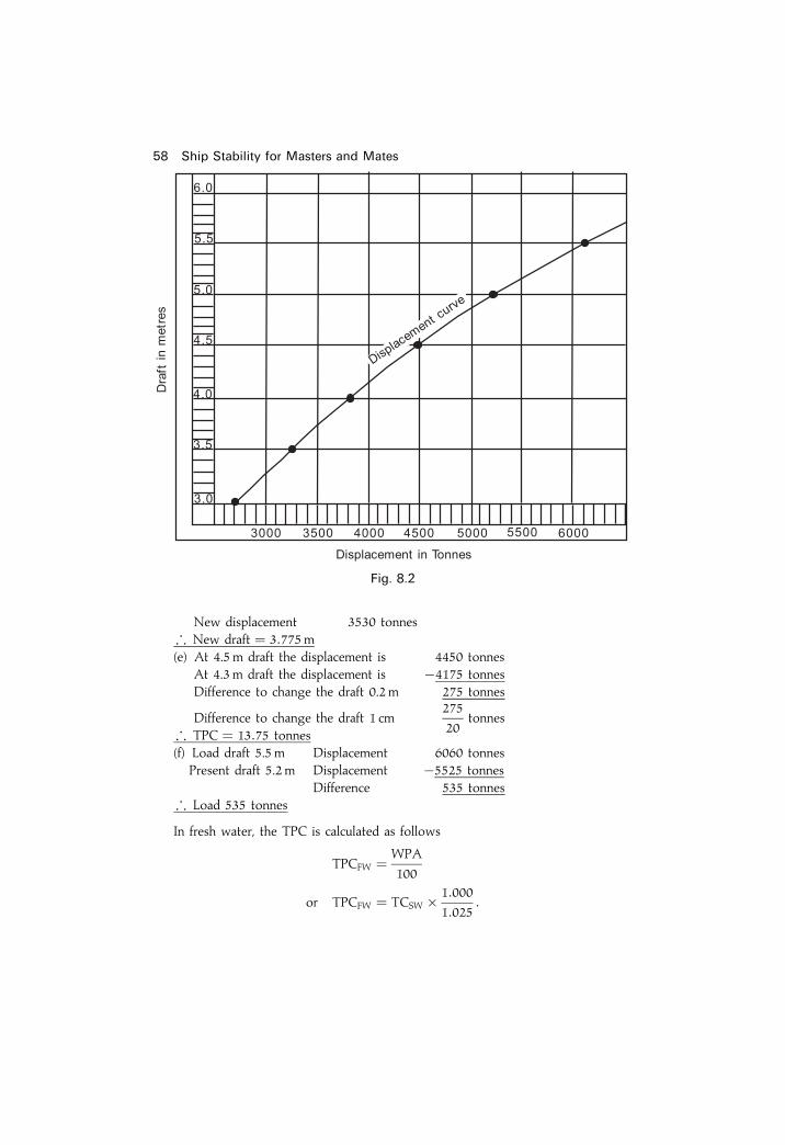
New displacement 3530 tonnes; New draft � 3:775m(e) At 4.5 m draft the displacement is 4450 tonnes
At 4.3 m draft the displacement is ÿ4175 tonnesDifference to change the draft 0.2 m 275 tonnes
Difference to change the draft 1 cm275
20tonnes
; TPC � 13:75 tonnes(f) Load draft 5.5 m Displacement 6060 tonnes
Present draft 5.2 m Displacement ÿ5525 tonnesDifference 535 tonnes
; Load 535 tonnes
In fresh water, the TPC is calculated as follows
TPCFW � WPA
100
or TPCFW � TCSW � 1:000
1:025:
58 Ship Stability for Masters and Mates
Fig. 8.2

TPC and displacement curves 59
Exercise 8
TPC curves
1 (a) Construct a TPC curve from the following data:Mean draft (m) 1 2 3 4 5TPC (tonnes) 3.10 4.32 5.05 5.50 5.73
(b) From this curve ®nd the TPC at drafts of 1.5 m and 2.1m.(c) If this ship ¯oats at 2.2m mean draft and then discharges 45 tonnes of
ballast, ®nd the new mean draft.2 (a) From the following information construct a TPC curve:
Mean draft (m) 1 2 3 4 5Area of water-plane (sqm) 336 567 680 743 777
(b) From this curve ®nd the TPC's at mean drafts of 2.5m and 4.5 m.(c) If, while ¯oating at a draft of 3.8 m, the ship discharges 380 tonnes of
cargo and loads 375 tonnes of bunkers, 5 tonnes of stores, and 125tonnes of fresh water, ®nd the new mean draft.
3 From the following information construct a TPC curve:Mean draft (m) 1 3 5 7TPC (tonnes) 4.7 10.7 13.6 15.5
Then ®nd the new mean draft if 42 tonnes of cargo is loaded whilst the shipis ¯oating at 4.5 m mean draft.
Displacement curves
4 (a) From the following information construct a displacement curve:Displacement (tonnes) 376 736 1352 2050 3140 4450Mean draft (m) 1 2 3 4 5 6
(b) From this curve ®nd the displacement at a draft of 2.3m.(c) If this ship ¯oats at 2.3m mean draft and then loads 850 tonnes of
cargo and discharges 200 tonnes of cargo, ®nd the new mean draft.(d) Find the approximate TPC at 2.5 m mean draft.
5 The following information is taken from a ship's displacement scale:Displacement (tonnes) 335 1022 1949 2929 3852 4841Mean draft (m) 1 1.5 2 2.5 3 3.5
(a) Construct the displacement curve for this ship and from it ®nd the draftwhen the displacement is 2650 tonnes.
(b) If this ship arrived in port with a mean draft of 3.5 m, discharged hercargo, loaded 200 tonnes of bunkers, and completed with a mean draftof 2 m, ®nd how much cargo she discharged.
(c) Assuming that the ship's light draft is 1 m, ®nd the deadweight whenthe ship is ¯oating in salt water at a mean draft of 1.75m.
6 (a) From the following information construct a displacement curve:Displacement (tonnes) 320 880 1420 2070 2800 3680Draft (m) 1 1.5 2 2.5 3 3.5
(b) If this ship's light draft is 1.1 m, and the load draft 3.5 m, ®nd thedeadweight.

60 Ship Stability for Masters and Mates
(c) If the vessel had on board 300 tonnes of cargo, 200 tonnes of ballast,and 60 tonnes of fresh water and stores, what would be the salt watermean draft.
7 (a) Construct a displacement curve from the following data:Draft (m) 1 2 3 4 5 6Displacement (tonnes) 335 767 1270 1800 2400 3100
(b) The ship commenced loading at 3m mean draft and, when work ceasedfor the day, the mean draft was 4.2m. During the day 85 tonnes of saltwater ballast had been pumped out. Find how much cargo had beenloaded.
(c) If the ship's light draft was 2m ®nd the mean draft after she had takenin 870 tonnes of water ballast and 500 tonnes of bunkers.
(d) Find the TPC at 3m mean draft.8 (a) From the following information construct a displacement curve:
Draft (m) 1 2 3 4 5 6Displacement (tonnes) 300 1400 3200 5050 7000 9000
(b) If the ship is ¯oating at a mean draft of 3.2 m, and then loads 1800tonnes of cargo and 200 tonnes of bunkers, and also pumps out 450tonnes of water ballast, ®nd the new displacement and ®nal mean draft.
(c) At a certain draft the ship discharged 1700 tonnes of cargo and loaded400 tonnes of bunkers. The mean draft was then found to be 4.5 m. Findthe original mean draft.

Chapter 9
Form coef®cientsThe coef®cient of ®neness of the water-planearea (Cw)The coef®cient of ®neness of the water-plane area is the ratio of the area ofthe water-plane to the area of a rectangle having the same length andmaximum breadth.In Figure 9.1 the area of the ship's water-plane is shown shaded and
ABCD is a rectangle having the same length and maximum breadth.
Coefficient of fineness �Cw� � Area of water-plane
Area of rectangle ABCD
� Area of water-plane
L� B
; Area of the water-plane � L� B� Cw
Example 1Find the area of the water-plane of a ship 36 metres long, 6 metres beam, whichhas a coef®cient of ®neness of 0.8.
Area of water-plane � L� B� Cw
� 36� 6� 0:8
Ans. Area of water-plane � 172:8 sqm
Fig. 9.1
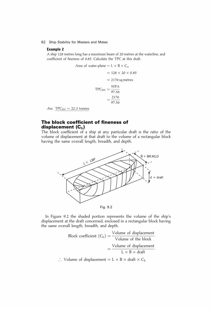
Example 2A ship 128 metres long has a maximum beam of 20 metres at the waterline, andcoef®cient of ®neness of 0.85. Calculate the TPC at this draft.
Area of water-plane � L� B� Cw
� 128� 20� 0:85
� 2176 sqmetres
TPCSW � WPA
97:56
� 2176
97:56
Ans. TPCSW � 22:3 tonnes
The block coef®cient of ®neness ofdisplacement (Cb)The block coef®cient of a ship at any particular draft is the ratio of thevolume of displacement at that draft to the volume of a rectangular blockhaving the same overall length, breadth, and depth.
In Figure 9.2 the shaded portion represents the volume of the ship'sdisplacement at the draft concerned, enclosed in a rectangular block havingthe same overall length, breadth, and depth.
Block coefficient �Cb� � Volume of displacement
Volume of the block
� Volume of displacement
L� B� draft
; Volume of displacement � L� B� draft� Cb
62 Ship Stability for Masters and Mates
Fig. 9.2

Ship's lifeboatsThe cubic capacity of a lifeboat should be determined by Simpson's rules orby any other method giving the same degree of accuracy. The accepted Cb
for a ship's lifeboat constructed of wooden planks is 0.6 and this is the®gure to be used in calculations unless another speci®c value is given. Thus,the cubic capacity of a wooden lifeboat can be found using the formula:
Volume � �L� B� Depth� 0:6� cubic metres.The number of persons which a lifeboat may be certi®ed to carry is equal
to the greatest whole number obtained by the formula V/x where `V' is thecubic capacity of the lifeboat in cubic metres and `x' is the volume in cubicmetres for each person. `x' is 0.283 for a lifeboat 7.3 metres in length orover, and 0.396 for a lifeboat 4.9 metres in length. For intermediate lengthsof lifeboats, the value of `x' is determined by interpolation.
Example 1Find the number of persons which a wooden lifeboat 10 metres long, 2.7 metreswide, and 1 metre deep may be certi®ed to carry.
Volume of the boat � �L� B� D� 0:6� cu:m� 10� 2:7� 1� 0:6
� 16:2 cu:m
Number of persons � V/x
� 16:2=0:283
Ans. Number of persons � 57
Example 2A ship 64 metres long, 10 metres maximum beam, has a light draft of 1.5metres and a load draft of 4 metres. The block coef®cient of ®neness is 0.6 atthe light draft and 0.75 at the load draft. Find the deadweight.
Light displacement � L� B� draft� Cb cu. m
� 64� 10� 1:5� 0:6
� 576 cu. m
Load displacement � L� B� draft� Cb cu. m
� 64� 10� 4� 0:75
� 1920 cu. m
Deadweight � Load displacement N Light displacement
� �1920N576� cu. mDeadweight � 1344 cu. m
� 1344� 1:025 tonnes
Ans. Deadweight � 1377:6 tonnes
Form coef®cients 63

The midships coef®cient (Cm)The midships coef®cient to any draft is the ratio of the transverse area ofthe midships Section (Am) to a rectangle having the same breadth anddepths.
In Figure 9.3 the shaded portion represents the area of the midshipssection to the waterline WL, enclosed in a rectangle having the samebreadth and depth.
Midships coefficient �Cm� � Midships area �Am�Area of rectangle
� Midships area �Am�B� d
orMidships area �Am� � B� d� Cm
The prismatic coef®cient (Cp)The prismatic coef®cient of a ship at any draft is the ratio of the volume ofdisplacement at that draft to the volume of a prism having the same lengthas the ship and the same cross-sectional area as the ship's midships area.The prismatic coef®cient is used mostly by ship-model researchers.In Figure 9.4 the shaded portion represents the volume of the ship's
displacement at the draft concerned, enclosed in a prism having the samelength as the ship and a cross-sectional area equal to the ship's midshipsarea (Am).
Prismatic coefficient �Cp� � Volume of ship
Volume of prism
� Volume of ship
L� Am
64 Ship Stability for Masters and Mates
Fig. 9.3

orVolume of ship � L� Am � Cp
NoteCm � Cp � Am
B� d� Volume of ship
L� Am
� Volume of ship
L� B� d
� Cb
; Cm � Cp � Cb
or
Cp � CB
Cm
Note. Cp is always slightly higher than CB at each waterline.Having described exactly what Cw, Cb, Cw and Cp are, it would be useful
to know what their values would be for several ship types.First of all it must be remembered that all of these form coef®cients will
never be more than unity.For the Cb values at fully loaded drafts the following table gives good
typical values:
Form coef®cients 65
Fig. 9.4
Ship type Typical Cb Ship type Typical Cb
fully loaded fully loaded
ULCC 0.850 General cargo ship 0.700Supertanker 0.825 Passenger liner 0.625Oil tanker 0.800 Container ship 0.575Bulk carrier 0.750 Coastal tug 0.500
medium form ships (Cb approx. 0.700), full-form ships (Cb > 0:700), ®ne-form ships (Cb < 0:700).

To extimate a value for Cw for these ship types at their fully loaded drafts,it is useful to use the following rule-of-thumb approximation.
Cw � �23� Cb� � 13 @ Draft Mld only!
Hence, for the oil tanker, Cw would be 0.867, for the general cargo shipCw would be 0.800 and for the tug Cw would be 0.667 in fully loadedconditions.For merchant ships, the midships coef®cient or midship area coef®cient is
0.980 to 0.990 at fully loaded draft. It depends on the rise-of-¯oor and thebilge radius. Rise of ¯oor is almost obsolete nowadays.As shown before;
Cp � Cb
Cm
Hence for the bulk carrier, when Cb is 0.750 with a Cm of 0.985, the Cp
will be:
Cp � 0:750
0:985� 0:761 @ Draft Mld
Cp is used mainly by researchers at ship-model tanks carrying out tests toobtain the least resistance for particular hull forms of prototypes.Cb and Cw change as the drafts move from fully loaded to light-ballast to
lightship conditions. The diagram (Figure 9.5) shows the curves at draftsbelow the fully loaded draft for a general cargo ship of 135.5 m LBP.`K' is calculated for the fully loaded condition and is held constant for all
remaining drafts down to the ship's lightship (empty ship) waterline.
66 Ship Stability for Masters and Mates
Fig. 9.5. Variation of Cb and Cw values with draft. (Note how the two curves are
parallel at a distance of 0.100 apart).

Form coef®cients 67
Exercise 9
1 (a) De®ne `coef®cient of ®neness of the water-plane'.(b) The length of a ship at the waterline is 100m, the maximum beam is
15m, and the coef®cient of ®neness of the water-plane is 0.8. Find theTPC at this draft.
2 (a) De®ne `block coef®cient of ®neness of displacement'.(b) A ship's length at the waterline is 120m when ¯oating on an even keel
at a draft of 4.5 m. The maximum beam is 20m. If the ship's blockcoef®cient is 0.75, ®nd the displacement in tonnes at this draft in saltwater.
3 A ship is 150m long, has 20m beam, load draft 8 m, light draft 3m. Theblock coef®cient at the load draft is 0.766, and at the light draft is 0.668.Find the ship's deadweight.
4 A ship 120m long� 15m beam has a block coef®cient of 0.700 and is¯oating at the load draft of 7 m in fresh water. Find how much more cargocan be loaded if the ship is to ¯oat at the same draft in salt water.
5 A ship 100m long, 15m beam, and 12m deep, is ¯oating on an even keelat a draft ot 6m, block coef®cient 0.8. The ship is ¯oating in salt water. Findthe cargo to discharge so that the ship will ¯oat at the same draft in freshwater.
6 A ship's lifeboat is 10m long, 3m beam, and 1.5 m deep. Find the numberof persons which may be carried.
7 A ship's lifeboat measures 10m� 2.5 m� 1m. Find the number of personswhich may be carried.

Chapter 10
Simpson's Rules forareas and centroidsAreas and volumesSimpson's Rules may be used to ®nd the areas and volumes of irregular®gures. The rules are based on the assumption that the boundaries of such®gures are curves which follow a de®nite mathematical law. When appliedto ships they give a good approximation of areas and volumes. Theaccuracy of the answers obtained will depend upon the spacing of theordinates and upon how near the curve follows the law.
Simpson's First RuleThis rule assumes that the curve is a parabola of the second order. Aparabola of the second order is one whose equation, referred to co-ordinateaxes, is of the form y � a0 � a1x� a2x
2, where a0, a1, and a2 are constants.Let the curve in Figure 10.1 be a parabola of the second order. Let y1, y2
and y3 be three ordinates equally spaced at `h' units apart.
Fig. 10.1

The area of the elementary strip is ydx. Then the area enclosed by thecurve and the axes of reference is given by
Area of figure ��2hO
ydx
But y � a0 � a1x� a2x2
; Area of figure ��2hO
�a0 � a1x� a2x2� dx
� a0x� a1x2
2� a2x
3
3
� �2hO
� 2a0h� 2a1h2 � 8
3 a2h3
Assume that the area of figure � Ay1 � By2 � Cy3
Using the equation of the curve and substituting `x' for O, h and 2hrespectively:
Area of figure � Aa0 � B�a0 � a1h� a2h2�
� C�a0 � 2a1h� 4a2h2�
� a0�A� B� C� � a1h�B� 2C�� a2h
2�B� 4C�; 2a0h� 2a1h
2 � 83 a2h
3 � a0�A� B� C� � a1h�B� 2C�� a2h
2�B� 4C�Equating coef®cients:
A� B� C � 2h, B� 2C � 2h, and B� 4C � 83 h
From which:
A � h
3; B � 4h
3; and C � h
3
; Area of figure � h
3�y1 � 4y2 � y3�
This is Simpson's First Rule.
It should be noted that Simpson's First Rule can also be used to ®nd the areaunder a curve of the third order, i.e., a curve whose equation, referred to theco-ordinate axes, is of the form y � a0 � a1x� a2x
2 � a3x3, where a0, a1,
a2 and a3 are constants.
Simpson's Rules for areas and centroids 69
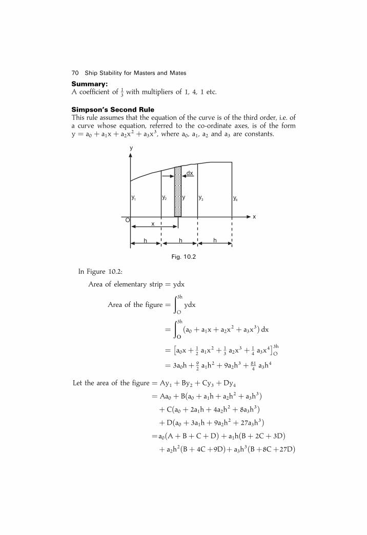
Summary:A coef®cient of 1
3 with multipliers of 1, 4, 1 etc.
Simpson's Second RuleThis rule assumes that the equation of the curve is of the third order, i.e. ofa curve whose equation, referred to the co-ordinate axes, is of the formy � a0 � a1x� a2x
2 � a3x3, where a0, a1, a2 and a3 are constants.
In Figure 10.2:
Area of elementary strip � ydx
Area of the figure ��3hO
ydx
��3hO
�a0 � a1x� a2x2 � a3x
3� dx
� a0x� 12 a1x
2 � 13 a2x
3 � 14 a3x
4� �3h
O
� 3a0h� 92 a1h
2 � 9a2h3 � 81
4 a3h4
Let the area of the figure � Ay1 � By2 � Cy3 � Dy4
� Aa0 � B�a0 � a1h� a2h2 � a3h
3�� C�a0 � 2a1h� 4a2h
2 � 8a3h3�
� D�a0 � 3a1h� 9a2h2 � 27a3h
3��a0�A� B� C� D� � a1h�B� 2C� 3D�� a2h
2�B� 4C�9D�� a3h3�B�8C�27D�
70 Ship Stability for Masters and Mates
Fig. 10.2

Equating coef®cients:A� B� C� D � 3h
B� 2C� 3D � 9
2h
B� 4C� 9D � 9h
B� 8C� 27D � 81
4h
From which:A � 3
8 h, B � 98 h, C � 9
8 h, and D � 38 h
; Area of figure � 38 hy1 � 9
8 hy2 � 98 hy3 � 3
8 hy4
orArea of figure � 3
8 h�y1 � 3y2 � 3y3 � y4�This is Simpson's Second Rule.
Summary:A coef®cient of 3
8 with multipliers of 1, 3, 3, 1 etc.
Simpson's Third RuleIn Figure 10.3:
Area of the elementary strip � ydx
Area between y1 and y2 in figure ��hO
ydx
� a0h� 12 a1h
2 � 13 a2h
3
Let the area between y1 and y2 � Ay1� By2 � Cy3
Simpson's Rules for areas and centroids 71
Fig. 10.3

Then area � Aa0�B�a0 � a1h+a2h2�
� C�a0 � 2a1h�4a2h2�� a0�A� B� C� � a1h�B� 2C�� a2h
2�B� 4C�Equating coef®cients:
A� B� C � h, B� 2C � h=2, B� 4C� h=3
From which:
A � 5h
12; B � 8h
12; and C � ÿ h
12
; Area of figure between y1 and y2 � 512 hy1 � 8
12 hy2 � �ÿ 112 hy3�
or
Area � h
12�5y1 � 8y2 ÿ y3�
This is the Five/eight (or Five/eight minus one) rule, and is used to ®nd the areabetween two consecutive ordinates when three consecutive ordinates are known.
Summary:A coef®cient of 1
12 with multipliers of 5, 8, ÿ1 etc.
Areas of water-planes and similar ®gures usingextensions of Simpson's RulesSince a ship is uniformly built about the centre line it is only necessary tocalculate the area of half the water-plane and then double the area found toobtain the area of the whole water-plane.
Figure 10.4 represents the starboard side of a ship's water-plane area. To®nd the area, the centre line is divided into a number of equal lengths each`h' m. long. The length `h' is called the common interval. The half-breadths, a,b, c, d, etc., are then measured and each of these is called a half-ordinate.
Using Simpson's First RuleThis rule can be used to ®nd areas when there are an odd number ofordinates.
Area of Figure 10.5(a) � h
3�a� 4b� c�
72 Ship Stability for Masters and Mates
Fig. 10.4

If the common interval and the ordinates are measured in metres, the areafound will be in square metres.Let this rule now be applied to a water-plane area such as that shown in
Figure 10.5(b).
The water-plane is divided into three separate areas and Simpson's FirstRule is used to ®nd each separate area.
Area 1 � h=3�a� 4b� c�Area 2 � h=3�c� 4d� e�Area 3 � h=3�e� 4f � g�
Area of 12 WP � Area 1� Area 2� Area 3
; Area of 12 WP � h=3�a� 4b� c� � h=3�c� 4d� e�
� h=3�e� 4f � g�or Area of 1
2 WP � h=3�a� 4b� 2c� 4d� 2e� 4f � g�This is the form in which the formula should be used. Within the bracketsthe half-ordinates appear in their correct sequence from forward to aft. The
Simpson's Rules for areas and centroids 73
Fig. 10.5(a)
Fig. 10.5(b)
1 4 1 1 4 1� �1 4 1
combined 1 4 2 4 2 4 1multiplier

coef®cients of the half-ordinates are referred to as Simpson's Multipliers andthey are in the form: 1424241. Had there been nine half-ordinates, theMultipliers would have been: 142424241. It is usually much easier to setout that part of the problem within the brackets in tabular form. Note howthe Simpson's multipliers begin and end with 1, as shown in Figure 10.5(b).
ExampleA ship 120 metres long at the waterline has equidistantly spaced half-ordinatescommencing from forward as follows:
0, 3.7, 5.9, 7.6, 7.5, 4.6, 0.1 metres respectively.
Find the area of the water-plane and the TPC at this draft.Note. There is an odd number of ordinates in the water-plane and therefore theFirst Rule can be used.
S1 is used because it is a total; using Simpson's First Rule:
h � 120
6� the common interval CI
; CI � 20 metres
Area of WP � 13� CI� S1 � 2 �for both sides�
� 13� 20� 90:5� 2
Ans. Area of WP � 1207 sqm
TPCSW � WPA
97:56� 1207
97:56
Ans. TPC � 12:37 tonnesNote. If the half-ordinates are used in these calculations, then the area of halfthe water-plane is found. If however the whole breadths are used, the total areaof the water-plane will be found. If half-ordinates are given and the WPA isrequested, simply multiply by 2 at the end of the formula as shown above.
74 Ship Stability for Masters and Mates
No. 12 ord. SM Area function
a 0 1 0b 3.7 4 14.8c 5.9 2 11.8d 7.6 4 30.4e 7.5 2 15.0f 4.6 4 18.4g 0.1 1 0.1
90:5 � S1
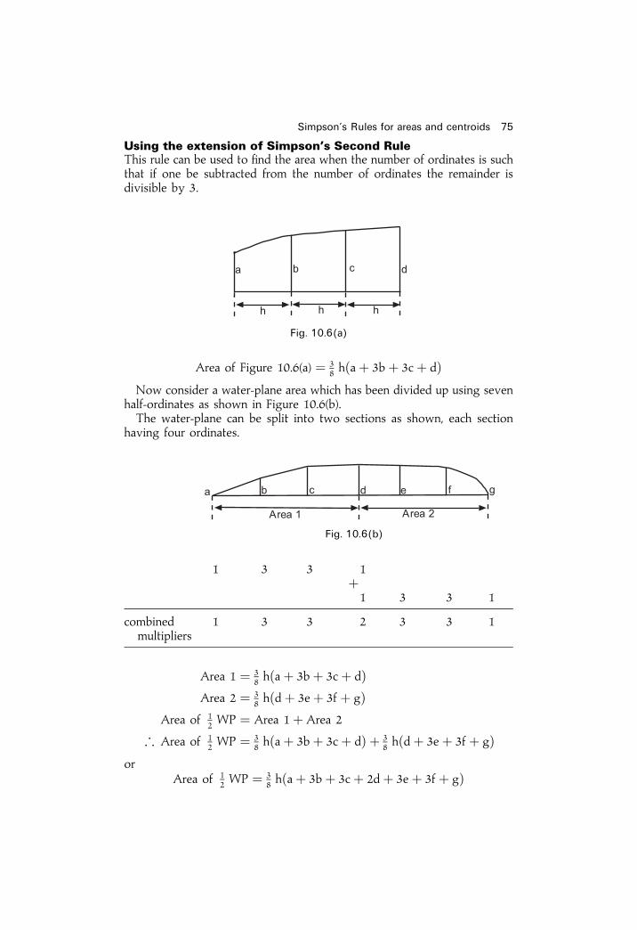
Using the extension of Simpson's Second RuleThis rule can be used to ®nd the area when the number of ordinates is suchthat if one be subtracted from the number of ordinates the remainder isdivisible by 3.
Area of Figure 10.6(a) � 38 h�a� 3b� 3c� d�
Now consider a water-plane area which has been divided up using sevenhalf-ordinates as shown in Figure 10.6(b).The water-plane can be split into two sections as shown, each section
having four ordinates.
Area 1 � 38 h�a� 3b� 3c� d�
Area 2 � 38 h�d� 3e� 3f � g�
Area of 12 WP � Area 1� Area 2
; Area of 12 WP � 3
8 h�a� 3b� 3c� d� � 38 h�d� 3e� 3f � g�
orArea of 1
2 WP � 38 h�a� 3b� 3c� 2d� 3e� 3f � g�
Simpson's Rules for areas and centroids 75
Fig. 10.6(a)
1 3 3 1�1 3 3 1
combined 1 3 3 2 3 3 1multipliers
Fig. 10.6(b)
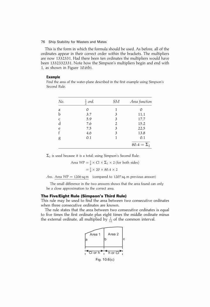
This is the form in which the formula should be used. As before, all of theordinates appear in their correct order within the brackets. The multipliersare now 1332331. Had there been ten ordinates the multipliers would havebeen 1332332331. Note how the Simpson's multipliers begin and end with1, as shown in Figure 10.6(b).
ExampleFind the area of the water-plane described in the ®rst example using Simpson'sSecond Rule.
S2 is used because it is a total; using Simpson's Second Rule:
Area WP � 38� CI� S2 � 2 �for both sides�
� 38� 20� 80:4� 2
Ans. Area WP � 1206 sqm (compared to 1207 sq. m previous answer)
The small difference in the two answers shows that the area found can onlybe a close approximation to the correct area.
The Five/Eight Rule (Simpson's Third Rule)This rule may be used to ®nd the area between two consecutive ordinateswhen three consecutive ordinates are known.The rule states that the area between two consecutive ordinates is equal
to ®ve times the ®rst ordinate plus eight times the middle ordinate minusthe external ordinate, all multiplied by 1
12 of the common interval.
76 Ship Stability for Masters and Mates
No. 12 ord. SM Area function
a 0 1 0b 3.7 3 11.1c 5.9 3 17.7d 7.6 2 15.2e 7.5 3 22.5f 4.6 3 13.8g 0.1 1 0.1
80:4 � S2
Fig. 10.6(c)

Thus: Area 1 � h
12�5a� 8bÿ c� or 1
12� CI� S3
Also: Area 2 � h
12�5c� 8bÿ a� or 1
12� CI� S3
S3 is used because it is a total; using Simpson's Third Rule. Consider thenext example.
ExampleThree consecutive ordinates in a ship's water-plane, spaced 6 metres apart, are14m, 15m, and 15.5 m respectively. Find the area between the last twoordinates.
Shaded Area � h
12�5a� 8bÿ c�
� 6
12�77:5� 120ÿ 14�
Ans. Area � 91:75 sqm
Volumes of ship shapes and similar ®guresLet the area of the elementary strip in Figures 10.7(a) and (b) be `Y' squaremetres. Then the volume of the strip in each case is equal to Y dx and thevolume of each ship is equal to
�4hO Y dx.
The value of the integral in each case is found by Simpson's Rules usingthe areas at equidistant intervals as ordinates. i.e.
Volume � h
3�A� 4B� 2C� 4D� E�
orCI
3� S1
Thus the volume of displacement of a ship to any particular draft can befound ®rst by calculating the areas of water-planes or transverse areas at
Simpson's Rules for areas and centroids 77
Fig. 10.6(d)

equidistant intervals and then using these areas as ordinates to ®nd thevolume by Simpson's Rules.
ExampleThe areas of a ship's water-planes are as follows:
Draft (m) 0 1 2 3 4Area of WP (sq m) 650 660 662 661 660
Calculate the ship's displacement in tonnes when ¯oating in salt water at 4metres draft. Also, if the ship's load draft is 4 metres. ®nd the FWA.
S1 is used because it is a total; using Simpson's First Rule:
78 Ship Stability for Masters and Mates
Fig. 10.7
Draft (m) Area SM Volume function
0 650 1 6501 660 4 26402 662 2 13243 661 4 26444 660 1 660
7918� S1
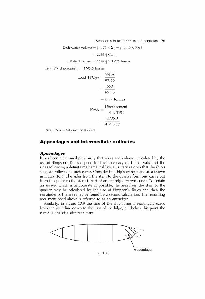
Underwater volume � 13� CI� S1 � 1
3� 1:0� 7918
� 2639 13 Cu. m
SW displacement � 2639 13� 1:025 tonnes
Ans. SW displacement � 2705:3 tonnes
Load TPCSW � WPA
97:56
� 660
97:56
� 6:77 tonnes
FWA � Displacement
4� TPC
� 2705:3
4� 6:77
Ans. FWA � 99.9 mm or 9.99 cm
Appendages and intermediate ordinates
AppendagesIt has been mentioned previously that areas and volumes calculated by theuse of Simpson's Rules depend for their accuracy on the curvature of thesides following a de®nite mathematical law. It is very seldom that the ship'ssides do follow one such curve. Consider the ship's water-plane area shownin Figure 10.8. The sides from the stem to the quarter form one curve butfrom this point to the stern is part of an entirely different curve. To obtainan answer which is as accurate as possible, the area from the stem to thequarter may be calculated by the use of Simpson's Rules and then theremainder of the area may be found by a second calculation. The remainingarea mentioned above is referred to as an appendage.Similarly, in Figure 10.9 the side of the ship forms a reasonable curve
from the waterline down to the turn of the bilge, but below this point thecurve is one of a different form.
Simpson's Rules for areas and centroids 79
Fig. 10.8

In this case the volume of displacement between the waterline (WL) andthe water-plane XY could be found by use of Simpson's Rules and then thevolume of the appendage found by means of a second calculation.
ExampleA ship's breadths, at 9 m intervals commencing from forward are as follows:
0, 7.6, 8.7, 9.2, 9.5, 9.4, and 8.5 metres respectively.
Abaft the last ordinate is an appendage of 50 sq m. Find the total area of thewater-plane.
80 Ship Stability for Masters and Mates
Fig. 10.9
Fig. 10.10
Ord. SM Product for area
0 1 07.6 4 30.48.7 2 17.49.2 4 36.89.5 2 19.09.4 4 37.68.5 1 8.5
149.7� S1

Area 1 � 13� CI� S1
Area 1 � 93� 149:7
Area 1 � 449:1 sq. m
Appendage � 50:0 sq. m � Area 2
Area of WP � 499:1 sq. m
Subdivided common intervalsThe area or volume of an appendage may be found by the introduction ofintermediate ordinates. Referring to the water-plane area shown in Figure10.11, the length has been divided into seven equal parts and the halfordinates have been set up. Also, the side is a smooth curve from the stemto the ordinate `g'.
If the area of the water-plane is found by putting the eight half-ordinatesdirectly through the rules, the answer obtained will obviously be anerroneous one. To reduce the error the water-plane may be divided intotwo parts as shown in the ®gure.Then,
Area No. 1 � h=3�a� 4b� 2c� 4d� 2e� 4f � g�To ®nd Area No. 2, an intermediate semi-ordinate is set up midwaybetween the semi-ordinates g and j. The common interval for this area ish/2.Then,
Area No. 2 � h=2� 13� �g� 4h� j�
or,Area No. 2 � h=3�12 g� 2h� 1
2 j�If CI is halved, then multipliers are halved, i.e. from 1, 4, 1 etc. to 1
2, 2,12.
Area of 12 WP � Area 1� Area 2
� h=3�a� 4b� 2c� 4d� 2e� 4f � g�� h=3�12 g� 2h� 1
2 j�� h=3�a� 4b� 2c� 4d� 2e� 4f � g� 1
2 g
� 2h� 12 j�
Simpson's Rules for areas and centroids 81
Fig. 10.11

� ���� �� �� � ������ �� ��� �� ��� � � � �
� �
� ��� �� �� �� �
�� �� ��
������� ���� ������ �� � ������ ����������� �� ��� ������� ��� ������� �� ��� �������������� ���������� ���� ������� ��� �� �������
�! ��"! "��! #��! #�#! #�"! �$! ��$ ��� ��" ������ ��������%��&�
'����& ������� ��� ���� ��� �������������� �� ��� ����� ������ �� ��$ �������(��� ��� ���� �� ��� �����������
���� � ��� )*� ��
)* � ����# � � ��+ �
���� �� � ��� � ��+� �� �,
���� ���� �� � �� �+��, �- �
.��� ��� ��� )* /��� ��� ��� ������ )* �� ��� ������ ������������*� ���� ����� �� �%�� ���� ���/���� ���/�� ��& �� �������� �& ��%����� ���
����������� ���� ����� �������� ����� �� ����� �� (��/�� ����� ��� ������/���������������� �������������� �� ��� ��� ��� ��� ������
���� � � ���� ��� ��� �� ��
� ������ �� ��� �� ��
���� � � ������ �� ��� � � ������ � � ���� �
� ��� �� ��� ������ �� ��� �
� ��
�� ���� ������� � � ������� ��� �����
�� ��� � ���� ������
� � ���" � � "�� � ����#�� �+��#�# � �,� #�" ��� �$ ��
� #����$ � ,�"��" �
� ���
�� �,� ��

Area 12 WP � Area 1� Area 2� Area 3
� h=3�12 a� 2b� 12 c� � c� 4d� 2e� 4f � g
� 12 g� 2h� 1
2 j
Area 12 WP � h=3�12 a� 2b� 1 1
2 c� 4d� 2e� 4f � 1 12 g
� 2h� 12 j� or h=3� S1
Example 2A ship's water-plane is 72 metres long and the lengths of the half-ordinatescommencing from forward are as follows:
0.2, 2.2, 4.4, 5.5, 5.8, 5.9. 5.9, 5.8, 4.8, 3.5 and 0.2 metres respectively.
Simpson's Rules for areas and centroids 83
Fig. 10.12
12 2 1
2 1 4 1� �1 4 1 1
2 2 12
combined multipliers 12 2 112 4 2 4 112 2 1
2
12 ord: SM Area function
0.2 12 0.1
2.2 2 4.44.4 112 6.65.5 4 22.05.8 2 11.65.9 4 23.65.9 2 11.85.8 4 23.24.8 112 7.23.5 2 7.00.2 1
2 0.1
117:6 � S1

The spacing between the ®rst three and the last three half-ordinates is half ofthe spacing between the other half-ordinates. Find the area of the water-plane.
Area � 13� CI� S1 � 2
CI � 72=8 � 9m
Area of WP � 13� 9� 117:6� 2
Ans. Area of WP � 705:6 sq. mNote. It will be seen from this table that the effect of halving the commoninterval is to halve the Simpson's Multipliers.S1 is because it is using Simpson's First Rule.
Areas and volumes having an awkward numberof ordinatesOccasionally the number of ordinates used is such that the area or volumeconcerned cannot be found directly by use of either the First or the SecondRule. In such cases the area or volume should be divided into two parts, thearea of each part being calculated separately, and the total area found byadding the areas of the two parts together.
Example 1Show how the area of a water-plane may be found when using six semi-ordinates. Neither the First nor the Second Rule can be applied directly to thewhole area but the water-plane can be divided into two parts as shown inFigure 10.13 Area No. 1 can be calculated using the First Rule and area No. 2by the Second Rule. The areas of the two parts may then be added together to®nd the total area.
An alternative method would be to ®nd the area between the half-ordinates aand e by the First Rule and then ®nd the area between the half-ordinates e and fby the `®ve-eight' Rule.
Example 2Show how the area may be found when using eight semi-ordinates.Divide the area up as shown in Figure 10.14. Find area No. 1 using the
Second Rule and area No. 2 using the First Rule.An alternative method is again to ®nd the area between the half-ordinates a
84 Ship Stability for Masters and Mates
Fig. 10.13

and g by the ®rst rule and the area between the half-ordinates g and h by the`®ve-eight' rule.In practice, the naval architect divides the ship's length into 10 stations and
then subdivides the forward and aft ends in order to obtain extra accuracy withthe calculations.In doing so, the calculations can be made using Simpson's First and Second
Rules, perhaps as part of a computer package.
Centroids and centres of gravity
To ®nd the centre of ¯otationThe centre of ¯otation is the centre of gravity or centroid of the water-planearea, and is the point about which a ship heels and trims. It must lie on thelongitudinal centre line but may be slightly forward or aft of amidships(from say 3 per cent L forward of amidships for oil tankers to say 3 per centL aft of amidships for container ships).To ®nd the area of a water-plane by Simpson's Rules, the half-breadths
are used as ordinates. If the moments of the half-ordinates about any pointare used as ordinates, then the total moment of the area about that pointwill be found. If the total moment is now divided by the total area, thequotient will give the distance of the centroid of the area from the pointabout which the moments were taken. This may be shown as follows:
In Figure 10.15:Area of strip � yEdx
Area of the 12 WP �
�LO
yEdx
Simpson's Rules for areas and centroids 85
Fig. 10.14
Fig. 10.15

Area of the WP � 2E�LO
yEdx
The value of the integral is found using the formula:�LO
yEdx � h
3�a� 4b� 2c� 4d� e�
Thus, the value of the integral is found by Simpson's Rules using values ofthe variable y as ordinates.
Moment of strip about OY � xEyEdx
Moment of 12 WP about OY �
�LO
xEyEdx
Moment of WP about OY � 2E�LO
xEyEdx
The value of this integral is found by Simpson's Rules using values of theproduct xEy as ordinates.Let the distance of the centre of ¯otation be �X from OY, then:
�X � Moment
Area
� 2E� LO xEyEdx
2E� LO yEdx
� S2
S1� CI
Example 1A ship 150 metres long has half-ordinate commencing from aft as follows:
0, 5, 9, 9, 9, 7 and 0 metres respectively.
Find the distance of the centre of ¯otation from forward (see Fig. 10.16).Note. To avoid using large numbers the levers used are in terms of CI thecommon interval. It is more ef®cient than using levers in metres (see table onfacing page).
Area of the water-plane � 23� CI� S1
� 23� 25� 376 sq. m
Distance of C. F. from aft � S2
S1� CI
� 376
120� CI
� 78:33m
Ans. C. F. is 78.33 m from aft
86 Ship Stability for Masters and Mates

This problem can also be solved by taking the moments about amidships asin the following example:
Example 2A ship 75m long has half-ordinates at the load water-plane commencing fromaft as follows:
0, 1, 2, 4, 5, 5, 5, 4, 3, 2 and 0 metres respectively.
The spacing between the ®rst three semi-ordinates and the last three semi-ordinates is half of that between the other semi-ordinates. Find the position ofthe Centre of Flotation relative to amidships.
Use � ve the sign for levers and moments AFT of amidships (�e�).Use ÿ ve sign for levers and moments FORWARD of amidships (�e�).
Simpson's Rules for areas and centroids 87
12 Ordinate SM Products for area Levers from A* Moment function
Aft 0 1 0 0 05 4 20 1 209 2 18 2 36
�e� 9 4 36 3 1089 2 18 4 727 4 28 5 140
Forward 0 1 0 6 0
120 � S1 376 � S2
* The Levers are in terms of the number of CI from the aft ordinate through to theforemost ordinate.S1, because it is the ®rst total.S2, because it is the second total.
Fig. 10.16
�e�
Fig. 10.17

�� � ��
�� ������
� �� ��� ���� � ������ �� ��� ��� � ��������� � ������� � ��� ������ � ����� � ��� �� ��� � ��� � � ���� !�� ���� ������ ��� ����� ��� ���� �������� � ���� � ����
"������� � �� #� �� � �������� � ��
�� ��
� �������
� �����
� ���$���� ��� ���� �� %� �� �� � �%�� � �������� �� #� �� ��$ ������ � �%�� � ��������
�� ��� ��� ��� ������ � � &���& �� ��� �����'������ ��� ������ � ������& � ��� ���%���� � � �� �� (���� �)� * ��� ��& �� �� � �������� ��������� �� �� ��� +����#����, ��� ����� � %����'������ ��� ���� ���� �� �- ������� ��������� �
���� ���%��� ��� +��� �� ��� %��������� ���� ��� � � �� � ������������� ���� ���� �& ���� ����� ����� �� ������� �� ��� � ���� ��� � ����� ������ ����� �� � ��� +��� ��� ���� ��+�� � �� ��� � ��� � ���� � ��� ���%���� � � �� �� � ��� +���� ��� ./ �� ���� � � �& ������ ���� ��� � ���� �� � ��� +��� �& ��� � � �� � ������������
�� ���� ������� �� ����� � ��� �����
� ������ �� ��� ������ ���� ���� ������
!�� 0 � 0 �1 0
� � �� � ��
� � � �� ��
1 1 $ �� ���� � 0 � �0
��� � 1 �0 0 0� � 0 � �01 1 $ �� ����
� 1�� �� ����� � 1�0 ��
� �1# �%�� 0
� 0 �1 0
���� � � ��� � ��

It will be noted that this procedure is similar to that for ®nding theposition of the Centre of Flotation, which is the two-dimensional centre ofgravity of each water-plane.
Example 1A ship is ¯oating upright on an even keel at 6.0m draft F and A. The areas ofthe water-planes are as follows:
Draft (m) 0 1 2 3 4 5 6Area (sq. m) 5000 5600 6020 6025 6025 6025 6025
Find the ship's KB at this draft.
KB � Moment about keel
volume of displacement
; KB � S2
S1� CI
� 323 630
105 715� 1:0
Ans. KB � 3.06 metres
� 0:51� d approximately.
Simpson's Rules for areas and centroids 89
Fig. 10.18
Water-plane Area SM Volume function Levers Moment function
A 6025 1 6025 6 36 150B 6025 4 24 100 5 120 500C 6025 2 12 050 4 48 200D 6025 4 24 100 3 72 300E 6020 2 12 040 2 24 080F 5600 4 22 400 1 22 400G 5000 1 5000 0 0
105 715 � S1 323 630 � S2

The lever of zero was at the keel so the ®nal answer was relative to this point,i.e. above base.If we Simpsonize 1
2 ords we will obtain areas.If we Simpsonize areas we will obtain volumes.
Example 2A ship is ¯oating upright in S.W. on an even keel at 7m draft F And A. TheTPC's are as follows:
Draft (m) 1 2 3 4 5 6 7TPC (tonnes) 60 60.3 60.5 60.5 60.5 60.5 60.5
The volume between the outer bottom and 1m draft is 3044 cu. m, and itscentre of gravity is 0.5 m above the keel. Find the ship's KB.
In Figure 10.19:
Let KY represent the height of the centre of gravity of volume A above thekeel, and KZ represent the height of the centre of gravity of volume B abovethe keel.
Let X � 100
1:025then the area of each water-plane is equal to TPC� X sqm
S1 denotes the ®rst total.S2 denotes the second total.}see Table below
90 Ship Stability for Masters and Mates
Fig. 10.19
Draft Area SM Volume function Levers 1 m Moment function
7 60.5 1 60.5 0 06 60.5 4 242.0 1 242.05 60.5 2 121.0 2 242.04 60.5 4 242.0 3 726.03 60.5 2 121.0 4 484.02 60.3 4 241.2 5 1206.01 60.0 1 60.0 6 360.0
1087:7 � S1 3260:0 � S2

Volume A � 1
3� CI� S1 � X
� 1
3� 1:0� 1087:7� 100
1:025� 35372
Volume A � 35372 cu. m
Volume B � �3044 cu. mTotal Volume � 38416 cu. m
XY � S2
S1� CI � Moment
Volume A
� 3260
1087:7� 1:0 � 3m below 7m waterline
XY � 3m
KX � 7m
KXÿ XY � KY, so KY � 4m
Moments about the keel
KB � Total moment
Total volume� 143 010
38 416� 3.72 metres
� 0.531�d
SummaryWhen using Simpson's Rules for ship calculations always use the followingprocedure
1 Make a sketch using the given information.2 Insert values into a table as shown in worked examples.3 Use tabulated summations to ®nally calculate requested values.
Simpson's Rules for areas and centroids 91
Volume KGkeel Moments about keel
35 372 4 141 488� 3 044 0.5 + 1 522
38 416 143 010
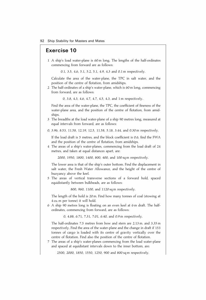
92 Ship Stability for Masters and Mates
Exercise 10
1 A ship's load water-plane is 60m long. The lengths of the half-ordinatescommencing from forward are as follows:
0.1, 3.5, 4.6, 5.1, 5.2, 5.1, 4.9, 4.3 and 0.1 m respectively.
Calculate the area of the water-plane, the TPC in salt water, and theposition of the centre of ¯otation, from amidships.
2 The half-ordinates of a ship's water-plane, which is 60m long, commencingfrom forward, are as follows:
0, 3.8, 4.3, 4.6, 4.7, 4.7, 4.5, 4.3, and 1m respectively:
Find the area of the water-plane, the TPC, the coef®cient of ®neness of thewater-plane area, and the position of the centre of ¯otation, from amid-ships.
3 The breadths at the load water-plane of a ship 90 metres long, measured atequal intervals from forward, are as follows:
0, 3.96, 8.53, 11.58, 12.19, 12.5, 11.58, 5.18, 3.44, and 0.30m respectively.
If the load draft is 5 metres, and the block coef®cient is 0.6, ®nd the FWAand the position of the centre of ¯otation, from amidships.
4 The areas of a ship's water-planes, commencing from the load draft of 24metres, and taken at equal distances apart, are:
2000, 1950, 1800, 1400, 800, 400, and 100 sqm respectively.
The lower area is that of the ship's outer bottom. Find the displacement insalt water, the Fresh Water Allowance, and the height of the centre ofbuoyancy above the keel.
5 The areas of vertical transverse sections of a forward hold, spacedequidistantly between bulkheads, are as follows:
800, 960, 1100, and 1120 sqm respectively.
The length of the hold is 20m. Find how many tonnes of coal (stowing at4 cu. m per tonne) it will hold.
6 A ship 90 metres long is ¯oating on an even keel at 6 m draft. The half-ordinates, commencing from forward, are as follows:
0, 4.88, 6.71, 7.31, 7.01, 6.40, and 0.9m respectively.
The half-ordinates 7.5 metres from bow and stern are 2.13m. and 3.35mrespectively. Find the area of the water-plane and the change in draft if 153tonnes of cargo is loaded with its centre of gravity vertically over thecentre of ¯otation. Find also the position of the centre of ¯otation.
7 The areas of a ship's water-planes commencing from the load water-planeand spaced at equidistant intervals down to the inner bottom, are:
2500, 2000, 1850, 1550, 1250, 900 and 800 sqm respectively.

Simpson's Rules for areas and centroids 93
Below the inner bottom is an appendage 1 metre deep which has a meanarea of 650 sqm. The load draft is 7 metres. Find the load displacement insalt water, the Fresh Water Allowance, and the height of the centre ofbuoyancy above the keel.
8 A ship's water-plane is 80 metres long. The breadths commencing fromforward are as follows:
0, 3.05, 7.1, 9.4, 10.2, 10.36, 10.3, 10.0, 8.84, 5.75 and 0m respectively.
The space between the ®rst three and the last three ordinates is half of thatbetween the other ordinates. Calculate the area of the water-plane, and theposition of the centre of ¯otation.
9 Three consecutive ordinates in a ship's water-plane area are:
6.3, 3.35, and 0.75m respectively.
The common interval is 6 m. Find the area contained between the last twoordinates.
10 The transverse horizontal ordinates of a ship's midships section commen-cing from the load waterline and spaced at 1 metre intervals are as follows:
16.30, 16.30, 16.30, 16.00, 15.50, 14.30, and 11.30 m respectively.
Below the lowest ordinate there is an appendage of 8.5 sq m. Find the areaof the transverse section.
11 The following table gives the area of a ship's water-plane at various drafts:Draft(m) 6 7 8Area(sq m) 700 760 800Find the volume of displacement and approximate mean TPC between thedrafts of 7 and 8m.
12 The areas of a ship's water-planes, commencing from the load water-planeand spaced 1 metre apart, are as follows:
800, 760, 700, 600, 450, and 10 sqm respectively.
Midway between the lowest two water-planes the area is 180 sqm. Findthe load displacement in salt water, and the height of the centre ofbuoyancy above the keel.

Chapter 11
Final KGWhen a ship is completed by the builders, certain written stabilityinformation must be handed over to the shipowner with the ship. Detailsof the information required are contained in the load line Rules, parts ofwhich are reproduced in Appendix I of this book. The information includesdetails of the ship's Lightweight, the Lightweight VCG and LCG, and alsothe positions of the centres of gravity of cargo and bunker spaces. Thisgives an initial condition from which the displacement and KG for anycondition of loading may be calculated. The ®nal KG is found by taking themoments of the weights loaded or discharged, about the keel. Forconvenience, when taking the moments, consider the ship to be on herbeam ends.In Figure 11.1(a), KG represents the original height of the centre of
gravity above the keel, and W represents the original displacement. Theoriginal moment about the keel is therefore W�KG.Now load a weight w1 with its centre of gravity at g1 and discharge w2
from g2. This will produce moments about the keel of w1�Kg1 and
(a) (b)
Fig. 11.1

w2�Kg2 in directions indicated in the ®gure. The ®nal moment about thekeel will be equal to the original moment plus the moment of the weightadded minus the moment of the weight discharged. But the ®nal momentmust also be equal to the ®nal displacement multiplied by the ®nal KG asshown in Figure 11.1(b). i.e.
Final moment � Final KG� Final displacement
or
Final KG � Final moment
Final displacement
Example 1A ship of 6000 tonnes displacement has KG� 6m and KM� 7.33m. Thefollowing cargo is loaded:
1000 tonnes; KG 2:5 m
500 tonnes; KG 3:5 m
750 tonnes; KG 9:0 m
The following is then discharged:
450 tonnes of cargo KG 0:6 m
and 800 tonnes of cargo KG 3:0 m
Find the ®nal GM.
Final KG 95
Weight KG Moment aboutthe keel
�6000 6.0 �36 000�1000 2.5 �2500�500 3.5 �1750�750 9.0 �6750�8250 �47 000ÿ450 0.6 ÿ270ÿ800 3.0 ÿ2400�7000 �44 330

Final KG � Final moment
Final displacement
� 44 330
7000� 6:33 m
GM � KMÿ KG
KM � 7:33 m; as given
Final KG � 6:33 m; as calculated
Ans. Final GM � 1.00 mNote. KM was assumed to be similar value at 6000 tonnes and 7000 tonnesdisplacement. This is feasible. As can be seen on Figure 6.2, it is possible tohave the same KM at two different drafts.
Example 2A ship of 5000 tonnes displacement has KG 4.5m, KM5.3m. The followingcargo is loaded:
2000 tonnes KG 3:7 m; and 1000 tonnes KG 7:5 m:
Find how much deck cargo (KG 9m) may now be loaded if the ship is to sailwith a minimum GM of 0.3 m.Let `x' tonnes of deck cargo be loaded, so that the vessel sails with
GM� 0.3 m.Final KM � 5:3 m
Final GM � 0:3 m
Final KG � 5:0 m
Final KG � Final moment
Final displacement� 5:0 m
; 5 � 37 400� 9x
8000� x40 000� 5x � 37 400� 9x
2600 � 4x
x � 650 tonnes
Ans. Maximum to load � 650 tonnes
96 Ship Stability for Masters and Mates
Weight KG Moment aboutthe keel
5000 4.5 22 5002000 3.7 74001000 7.5 7500
x 9.0 9x
8000� x 37 400 � 9x

Final KG 97
Exercise 11
1 A ship has a displacement of 1800 tonnes and KG� 3m. She loads 3400tonnes of cargo (KG� 2.5 m), and 400 tonnes of bunkers (KG� 5.0 m).Find the ®nal KG.
2 A ship has a light displacement of 2000 tonnes and light KG� 3.7m. Shethen loads 2500 tonnes of cargo (KG� 2.5 m), and 300 tonnes of bunkers(KG� 3m). Find the new KG.
3 A ship sails with displacement 3420 tonnes and KG� 3.75m. During thevoyage bunkers were consumed as follows: 66 tonnes (KG� 0.45m) and64 tonnes (KG� 2m). Find the KG at the end of the voyage.
4 A ship has displacement 2000 tonnes and KG� 4m. She loads 1500 tonnesof cargo (KG� 6m), 3500 tonnes of cargo (KG� 5m), and 1520 tonnes ofbunkers (KG� 1 m). She then discharges 2000 tonnes of cargo(KG� 2.5m) and consumes 900 tonnes of oil fuel (KG� 0.5 m) duringthe voyage. Find the ®nal KG on arrival at the port of destination.
5 A ship has a light displacement of 2000 tonnes (KG� 3.6m). She loads2500 tonnes of cargo (KG� 5m) and 300 tonnes of bunkers (KG� 3m).The GM is then found to be 0.15m. Find the GM with the bunkers empty.
6 A ship has a displacement of 3200 tonnes (KG� 3m, and KM� 5.5 m) Shethen loads 5200 tonnes of cargo (KG� 5.2 m). Find how much deck cargohaving a KG� 10m may now be loaded if the ship is to complete loadingwith a positive GM of 0.3m.
7 A ship of 5500 tonnes displacement has KG 5m, and she proceeds to loadthe following cargo:
1000 tonnes KG 6 m700 tonnes KG 4 m300 tonnes KG 5 m
She then discharges 200 tonnes of ballast KG 0.5 m. Find how much deckcargo (KG� 10 m) can be loaded so that the ship may sail with a positiveGM of 0.3 metres. The load KM is 6.3 m.
8 A ship of 3500 tonnes light displacement and light KG 6.4m has to load9600 tonnes of cargo. The KG of the lower hold is 4.5m, and that of thetween deck is 9m. The load KM is 6.2 m and, when loading is completed,the righting moment at 6 degrees of heel is required to be 425 tonnes m.Calculate the amount of cargo to be loaded into the lower hold and tweendeck respectively (Righting moment�W�GM� sin heel.)
9 A ship arrives in port with displacement 6000 tonnes and KG 6m. She thendischarges and loads the following quantities:
Discharge 1250 tonnes of cargo KG 4.5 metres675 tonnes of cargo KG 3.5 metres420 tonnes of cargo KG 9.0 metres
Load 980 tonnes of cargo KG 4.25 metres550 tonnes of cargo KG 6.0 metres

98 Ship Stability for Masters and Mates
700 tonnes of bunkers KG 1.0 metre70 tonnes of FW KG 12.0 metres
During the stay in port 30 tonnes of oil (KG 1m) are consumed. If the ®nalKM is 6.8 m, ®nd the GM on departure.
10 A ship has light displacement 2800 tonnes and light KM 6.7 m. She loads400 tonnes of cargo (KG 6m) and 700 tonnes (KG 4.5 m). The KG is thenfound to be 5.3m. Find the light GM.
11 A ship's displacement is 4500 tonnes and KG 5m. The following cargo isloaded:
450 tonnes KG 7.5 m120 tonnes KG 6.0 m650 tonnes KG 3.0 m.
Find the amount of cargo to load in a 'tween deck (KG 6m) so that the shipsails with a GM of 0.6m. (The load KM is 5.6 m)
12 A ship of 7350 tonnes displacement has KG 5.8 m and GM 0.5m. Findhow much deck cargo must be loaded (KG 9m) if there is to be ametacentric height of not less than 0.38m when loading is completed.
13 A ship is partly loaded and has a displacement of 9000 tonnes, KG 6m, andKM 7.3m. She is to make a 19-day passage consuming 26 tonnes of oil perday (KG 0.5m). Find how much deck cargo she may load (KG 10m) if theGM on arrival at the destination is to be not less than 0.3 m.

Chapter 12
Calculating KB, BM,and metacentricdiagramsTHE method used to determine the ®nal position of the centre of gravitywas examined in the previous chapter. To ascertain the GM for anycondition of loading it is necessary also to calculate the KB and BM (i.e.KM) for any draft.
To ®nd KBThe centre of buoyancy is the centre of gravity of the underwater volume.For a box-shaped vessel on an even keel, the underwater volume is
rectangular in shape and the centre of buoyancy will be at the half-length,on the centre line, and at half the draft as shown in Figure 12.1(a).Therefore, for a box-shaped vessel on an even keel: KB� 1
2 draft.
For a vessel which is in the form of a triangular prism as shown in Figure12.1(b) the underwater section will also be in the form of a triangular prism.The centroid of a triangle is at 2/3 of the median from the apex. Thereforethe centre of buoyancy will be at the half-length, on the centre line, but theKB� 2/3 draft.For an ordinary ship the KB may be found fairly accurately by Simpson's
Rules as explained in Chapter 10. The approximate depth of the centre ofbuoyancy of a ship below the waterline usually lies between 0.44� draft
Fig. 12.1(a). Box-shaped vessel

and 0.49� draft. A closer approximation of thus depth can be obtained byusing Morrish's Formula, which states:
Depth of centre of buoyancy below waterline � 1
3
�d
2� V
A
�where
d � Mean draftV � Volume of displacement
andA � Area of the water-plane
The derivation of this formula is as follows:In Figure 12.2, let ABC be the curve of water-plane areas plotted against
drafts to the load waterline. Let DE� V/A and draw EG parallel to the basecutting the diagonal FD in H.It must ®rst be shown that area DAHC is equal to area DABC.
Rectangle AH � Rectangle HC; Triangle AGH � Triangle HEC
andArea AHCD � Area AGEDArea AGED � V/A� A
� Vbut
Area DABC � V
; Area DAHC � Area DABC
100 Ship Stability for Masters and Mates
Fig. 12.1(b). Triangular-shaped vessel
Fig. 12.1(c). Ship-shaped vessel

The distance of the centroid of DABC below AD is the distance of thecentre of buoyancy below the load waterline. It is now assumed that thecentroid of the area DAHC is the same distance below the load waterline asthe centroid of area DABC.To ®nd the distance of the centroid of area DAHC below AD.
Area AGH
Area AGED�
12 AGEGHAGEAD
� 1
2
GH
AD
� 1
2
GF
AF
� 1
2
AFÿ AG
AF
� 1
2
�dÿ AG
d
�; Area AGH � 1
2�dÿV/A�
d � Area AGED
The centroid of AGED is1
2
V
Afrom AD.
Now let triangle AGH be shifted to HEC.The centroid of AGED will move parallel to the shift of the centroid of
AGH and the vertical component of this shift (x) is given by:
Calculating KB, BM, and metacentric diagrams 101
Fig. 12.2

x � AGH� d/3
AGED
�1
2
�dÿ V/A
d
�� d
3� AGED
AGED
� 1
2
�dÿ V/A
d
�� d
3
� 1
6�dÿ V/A�
The new vertical distance of the centroid below AD will now be given by:
Distance below AD � 1
2
V
A� 1
6
�dÿ V
A
�� 1
3
V
A� 1
6d
� 1
3
�d
2� V
A
�Therefore the distance of the centre of buoyancy below the load waterline
is given by the formula:
Distance below LWL � 1
3
�d
2� V
A
�This is known as Morrish's or Normand's formula and will give very good
results for merchant ships.
To ®nd Transverse BMThe Transverse BM is the height of the transverse metacentre above thecentre of buoyancy and is found by using the formula:
BM � 1
V
where
1 � The second moment of the water-plane area about the centre line,
andV � The ship's volume of displacement
The derivation of this formula is as follows:Consider a ship inclined to a small angle (y) as shown in Figure 12.3(a)
Let `y' be the half-breadth.
102 Ship Stability for Masters and Mates

Since y is a small angle then arc WW1 � arc LL1
� y y
Also:
Area of wedge WOW1 � Area of wedge LOL1
� 12 y y
2
Consider an elementary wedge of longitudinal length dx as in Figure12.3(b).
Calculating KB, BM, and metacentric diagrams 103
Fig. 12.3(a)
Fig. 12.3(b)

The volume of this wedge � 12 y y
2 dx
The moment of the wedge about the centre line � 12 y y
2 dx� 23 y
� 13 y y
3 dx
The total moment of both wedgesabout the centre line
� 23 y y
3 dx
The sum of the moments of all such wedges ��LO
23 y y
3 dx
� y�LO
23 y
3 dx
But �LO
23 y
3 dx �The second momentof the water-planearea about the ship0s centre line
�� I
;The sum of the momentsof the wedges � I� y
But the sum ofthe moments � v� gg1
where v is the volume of the immersed or emerged wedge.
; I� y � v� gg1or
I � v� gg1y
�I�Now:
BB1 � v� gg1V
andBB1 � BM� y
; BM� y � v� gg1V
or
BM� V � v� gg1y
Substituting in (I) above:BM� V � I
; BM � I
V
104 Ship Stability for Masters and Mates

For a rectangular water-plane area the second moment about the centre lineis found by the formula:
I � LB3
12
where L� the length of the water-plane, and B = the breadth of the water-plane, (the derivation of this formula is shown in Chapter 29).Thus, for a vessel having a rectangular water-plane area:
BM � LB3
12V
For a box-shaped vessel:
BM � 1
V
� LB3
12V
� L� B3
12� L� B� draft
; BM � B2
12d
where B� the beam of the vessel, and d� any draft of the vessel. B is aconstant, d is a variable.For a triangular-shaped prism:
BM � I
V
� LB3
12V
� L� B3
12�12� L� B� draft�
; BM � B2
6d
where B is the breadth at the waterline and d is the corresponding draft. Band d are variables.
Example 1A box-shaped vessel is 24m� 5m� 5m and ¯oats on an even keel at 2mdraft. KG� 1.5 m. Calculate the initial metacentric height.
Calculating KB, BM, and metacentric diagrams 105

KB � 1
2draft BM � B2
12dKB � 1:00m
BM � �1:04mKB � 1m BM � 52
12� 2KM � 2:04m
KG � ÿ1:50mBM � 1:04m GM � 0:54m
Ans. GM � �0:54m
Example 2A vessel is in the form of a triangular prism 32m long, 8 m wide at the top, and5m deep. KG� 3.7 m. Find the initial metacentric height when ¯oating oneven keel at 4m draft F and A.Let `x' be the half-breadth at the waterline, as shown in Figure 12.4.
Thenx
4� 4
5
x � 16
5x � 3:2m
; The breadth at the waterline � 6:4m
KB � 2=3 draft BM � B2
6dKB � 2:67m
� 2=3� 4 BM � �1:71mKB � 2:67m � 6:4� 6:4
6� 4KM � 4:38m
KG � ÿ3:70mBM � 1:71m GM � 0:68m
Ans. GM � �0:68mNote how the breadth `B' would decrease at the lower drafts. See also Figure12.6(b).
106 Ship Stability for Masters and Mates
Fig. 12.4

Example 3The second moment of a ship's water-plane area about the centre line is20 000m4 units. The displacement is 7000 tonnes whilst ¯oating in dock waterof density 1008 kg per cu. m. KB� 1.9 m, and KG� 3.2m. Calculate the initialmetacentric height.
Volume of water displaced � 7000� 1000
1008cu. m � 6944 cu. m
BM � I
V
; BM � 20 000
6944
BM � 2:88m
KB � �1:90mKM � 4:78m
KG � 3:20m
Ans. GM � �1:58m
Metacentric diagramsIt has been mentioned in Chapter 6 that the of®cer responsible for loading aship should aim to complete the loading with a GMwhich is neither too largenor too small. See table of typical GMvalues on p. 49 formerchant ships whenfully loaded. A metacentric diagram is a ®gure in graph form from which theKB, BM, and thus the KM can be found for any draft by inspection. If the KG isknown and the KM is found from the diagram, the difference will give theGM. Also, if a ®nal GM be decided upon, the KM can be taken from the graphand the difference will give the required ®nal KG.The diagram is usually drawn for drafts between the light and loaded
displacements, i.e. 3 m and 13m respectively overpage.Figure 12.5 shows a metacentric diagram drawn for a ship having the
following particulars:
Draft (m) KB (m) KM (m)
13 6.65 11.6012 6.13 11.3011 5.62 11.1410 5.11 11.109 4.60 11.158 4.10 11.487 3.59 11.946 3.08 12.815 2.57 14.304 2.06 16.633 1.55 20.54± ± ±
Calculating KB, BM, and metacentric diagrams 107

108 Ship Stability for Masters and Mates
Fig. 12.5. Metacentric diagram for a ship-shaped vessel.

��� ������� �� � ��������� �� ��� ����� ��� � ��������� ���� ������ ��� ����� � ��� ������� �� � ��������� � ����� �� ������� � ���� ���� ���� ����� ���� ��� ����������� ��� �� �� ���������� ��� ����� �� ��� ������ �� ������� �� ������ ���� ���� ���� ���� ��� �������� � ��� ��� �������� ���� � !� "
#$�� �#$� " #%� ���� � �� � �� #�!!� " $� �����&�� ����� ����� ������� �� ���� ��� �� ������ ' �������� �� ���� �� ����
����� �� ��� � ������� ��� ������� ��� ��������� ���� �� �� ������ (������� #%�!�)��� ��� �* ����� �� +���� �� *���������� ��� ���� ���� ���� ���
�������� � �* ����� ��� � ��� ������,� #$� ���� ##� -�� ,� #%� ���� ##�$-� � �� � �� �� ������
%-�!.� �* " $� ���������� ����� ��� ��� /��� �� � ������ ����� �� ���� � ����� #%�!�)��� ��� �� �� �������� ��� ��� ������� ����� �� ���� ��� ���� ����� ��
�* � ��� ��� �� ����� ���� 0� �� #$� ����������������� �� ���� ��� ���� ��� � ��� �������� ������ ������ ��� �� ���
� ��� �* ����� ���� ��� �* �������� 1 ��� ��2� � �*2� ��� �������� ������� ��� ������� ���� ���
���� ��� �� ��� �������
������� ��������� ��� ���������� ����� ��� � ��������� ������ .� ��� #-������ � � ���� ��� ��� ���� ����� �� -�! � �������� ������ ��� ���� ���� # ����� � ��� ��� ���� ! �� ,���� ���� ��� ����� 1 3
4�5 ��� ������ �* � ��� ���� �� ����� �� ������� � 4�5 ��� �* �� $�! ��
����� ��� #% ����� �� �%��� �� ��� �
#� -�!� 6�$$� 6�6$�#�! � -�0!� !�! � �$#�%� #�-� .�#0� !�#0�%�! � #�%!� $�$$� .�!6�$�- � #�!� %�06� .�%6�$�! � #�0!� %�$6� .�#$�.�- � %�--� %�-6� .�-6�.�! � %�%!� #�6!� .�#-�!�- � %�!� #� 0� .�#0�
(�� ����� #%� 4�5 ��� �� � �* ������ ����� �����
����������� �� 1 ��� ������ �*� ��� � ����7���� ���� �� ��� ���������� �� ��� ����� �� ����������� ���� ������ ,� ��� ���� ����� ��� �������� ��� ����� ���� ��� ��� ������ �* � ��� ���� �� ����� �� ������������ '� �� ���� ����� ���� ��� � ��������� ������ ��� ������ �* � ��� ���� �� ����� �� ������ ��� ���� ��� �� �8
��� �
� ����� � �� ��� �����
���������� �� � � ��� ����������� ������� ���

��� ���� ������� � � ������� ��� �����
���� �������� ����������� ������� � � � �������� ������

���������� ��� ���� �� �� ��� �� ��� ������� ���
������ �� � ����� �������� � ����� ������ �� ��� �� � ��� � ����� ������ ��� ������ ! � ��� ��"� � ��
��"" ��#� ��� �� $%����&����������� ��� ���� �� �� ��� �� ��� ������� ���
�� � ��� � ���� � %������ ���� ���� ��� '�()�� �� #����"� ��� ������ �� � ��� ���� � ������� ������ �� '��� ��#� '* ��� �( ������ �+
���,�� ����� � �� ���" �� ���
#����"-� '����� � ��� ��
.�� '�()�� �� #����"�
�� � �%� �%
/%��0�
���
��� /%� �%
/%�%
.�� ������ ������
��� 1
� 1 � /%� �%
/%�%
�% � ,�%
�� � �� ���
,�
2�'�������� � ������ $0& '�#��
������ �� � �
%���,� � �
%���,�/%�
� ,�� ,�/%
���,�
������ �� � �� ���,�
.����� /%�,$'& ����� ��������� ����� ��� �����"�)�� �� ������������ ���� �( � ��� '��� 3��� ��� ��� �� #"��� �#� ������� �������"�� ����� �� ��� �'�"�� ���#� �� ��� ������"� ��"" ����� 3��� "�� ����� ������� ���� ����� ������ � �����
���������� �� � � ��� ����������� ������� ���

112 Ship Stability for Masters and Mates
Fig. 12.6(b). Metacentric diagram for triangular-shaped vessel.

Calculating KB, BM, and metacentric diagrams 113
Exercise 12
1 A box-shaped vessel 75m long, 12m beam and 7m deep, is ¯oating on aneven keel at 6m draft. Calculate the KM.
2 Compare the initial metacentric heights of two barges, each 60m. long,10m beam at the waterline, 6 m deep, ¯oating upright on an even keel at3 m draft, and having KG� 3m. One barge is in the form of a rectangularprism and the other is in the form of a triangular prism, ¯oating apexdownwards.
3 Two box-shaped vessels are each 100m long, 4 m deep, ¯oat at 3 m draft,and have KG� 2.5 m. Compare their initial Metacentric Heights if one has10m beam and the other has 12m beam.
4 Will a homogeneous log of square cross-section and relative density 0.7have a positive initial Metacentric Height when ¯oating in fresh water withone side parallel to the waterline? Verify your answer by means of acalculation.
5 A box-shaped vessel 60m� 12 m� 5m is ¯oating on an even keel at adraft of 4m. Construct a metacentric diagram for drafts between 1m and4m. From the diagram ®nd:(a) the KM's at drafts of 2.4 m and 0.9m, and(b) the draft at which the minimum KM occurs.
6 Construct a metacentric diagram for a box-shaped vessel65m� 12m� 6m for drafts between 1m and 6m. From the diagram ®nd:(a) the KM's at drafts of 1.2 m and 3.6m, and(b) the minimum KM and the draft at which it occurs.
7 Construct a metacentric diagram for a box-shaped vessel 70m long and10m beam, for drafts between 1m and 6m. From the diagram ®nd:(a) the KM's at drafts of 1.5 m and 4.5m, and(b) the draft at which the minimum KM occurs.
8 A box-shaped vessel is 60m long, 13.73m wide and ¯oats at 8m even-keeldraft in salt water.(a) Calculate the KB, BM and KM values for drafts 3 m to 8m at intervals
of 1 m. From your results draw the Metacentric Diagram.(b) At 3.65m draft even keel, it is known that the VCG is 4.35m above
base. Using your diagram, estimate the transverse GM for thiscondition of loading.
(c) At 5.60m draft even keel, the VCG is also 5.60m above base. Usingyour diagram, estimate the GM for this condition of loading. Whatstate of equilibrium is the ship in?
Draft (m) 3 4 5 6 7 8
KM (m) 6.75 5.94 5.64 5.62 5.75 5.96
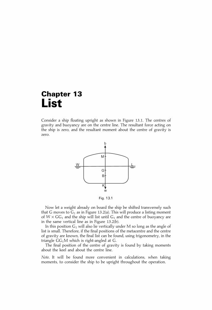
Chapter 13
ListConsider a ship ¯oating upright as shown in Figure 13.1. The centres ofgravity and buoyancy are on the centre line. The resultant force acting onthe ship is zero, and the resultant moment about the centre of gravity iszero.
Now let a weight already on board the ship be shifted transversely suchthat G moves to G1 as in Figure 13.2(a). This will produce a listing momentof W�GG1 and the ship will list until G1 and the centre of buoyancy arein the same vertical line as in Figure 13.2(b).In this position G1 will also lie vertically under M so long as the angle of
list is small. Therefore, if the ®nal positions of the metacentre and the centreof gravity are known, the ®nal list can be found, using trigonometry, in thetriangle GG1M which is right-angled at G.The ®nal position of the centre of gravity is found by taking moments
about the keel and about the centre line.
Note. It will be found more convenient in calculations, when takingmoments, to consider the ship to be upright throughout the operation.
Fig. 13.1

Example 1A ship of 6000 tonnes displacement has KM� 7.3m, and KG� 6.7m, and is¯oating upright. A weight of 60 tonnes already on board is shifted 12mtransversely. Find the resultant list.Figure 13.3(a) shows the initial position of G before the weight was shifted
and Figure 13.3(b) shows the ®nal position of G after the weight has beenshifted.When the weight is shifted transversely the ship's centre of gravity will also
shift transversely, from G to G1. The ship will then list y degrees to bring G1
vertically under M the metacentre.
GG1 � w� d
W
� 60� 12
6000
GG1 � 0:12m
GM � KMÿ KG � 7:3ÿ 6:7 � 0:6m
In triangle GG1M:
tan y � GG1
GM
� 0:12
0:60� 0:20
Ans. List � 11� 18 120
Example 2A ship of 8000 tonnes displacement has KM� 8.7 m, and KG� 7.6 m. Thefollowing weights are then loaded and discharged:Load 250 tonnes cargo KG 6.1m and centre of gravity 7.6m to starboard of
the centre line.
List 115
Fig. 13.2

Load 300 tonnes fuel oil KG 0.6m and centre of gravity 6.1 m to port of thecentre line.Discharge 50 tonnes of ballast KG 1.2m and centre of gravity 4.6m to port
of the centre line.Find the ®nal list.
Note. In this type of problem ®nd the ®nal KG by taking moments about thekeel, and the ®nal distance of the centre of gravity from the centre line bytaking moments about the centre line.
Moments about the keel
Final KG � Final moment
Final displacement
� 62 445
8500
Final KG � 7:35m
KM � 8:70m
Final KG � ÿ7:35mFinal GM � 1:35m
116 Ship Stability for Masters and Mates
Fig. 13.3
Weight KG Moments about keel
8000 7.6 60 800250 6.1 1 525300 0.6 180
8550 62 505ÿ50 1.2 ÿ608500 62 445

Moments about the centre line (as in Figure 13.4(a))For levers to port, use � ve sign.For levers to starboard, use ÿ ve sign.
Let the ®nal position of the centre of gravity be as shown in Figure 13.4(b)
; Final listing moment � W� GG1
or
GG1 � Final moment
Final displacement
� ÿ3008500
� ÿ0:035m
GG1 � 0:035m to starboard, because of the ÿ ve sign used in table:
Since the ®nal position of the centre of gravity must lie vertically under M, itfollows that the ship will list y degrees to starboard.
List 117
Fig. 13.4
w d Listing moment
to port to starboard� ve ÿ ve
�250 ÿ7:6 ± ÿ1900ÿ50 �4:6 ± ÿ230�300 �6:1 �1830 ±
�1830 ÿ2130�1830
®nal moment ÿ300

tan y � GG1
GM
� ÿ0:0351:35
� ÿ0:0259
; y � 1� 29 0
Ans. Final list � 1� 290 to starboard
Example 3A ship of 8000 tonnes displacement has a GM� 0.5 m. A quantity of grain inthe hold, estimated at 80 tonnes, shifts and, as a result, the centre of gravity ofthis grain moves 6.1 m horizontally and 1.5 m vertically. Find the resultant list.
Referring to Figure 13.5, let the centre of gravity of the grain shift from g to g2.This will cause the ship's centre of gravity to shift from G to G2 in a directionparallel to gg2. The horizontal components of these shifts are g to g1 and G toG1 respectively, whilst the vertical components are g1g2 and G1G2.
GG1 � w� d
W
� 80� 6:1
8000
GG1 � 0:061m
G1G2 � w� d
W
� 80� 1:5
8000
G1G2 � 0:015m
In Figure 13.5
GX � G1G2
GX � 0:015m
GM � 0:500m
XM � 0:485m
XG2 � GG1
XG2 � 0:061m
tan y � XG2
MX
tan y � 0:061
0:485� 0:126
tan y � 0:126
Ans. List � 7� 120
118 Ship Stability for Masters and Mates
Fig. 13.5

Example 4A ship of 13 750 tonnes displacement, GM� 0.75m, is listed 212 degrees tostarboard and has yet to load 250 tonnes of cargo. There is space available ineach side of No 3 between deck (centre of gravity, 6.1m out from the centreline). Find how much cargo to load on each side if the ship is to be upright oncompletion of loading.Load `w' tonnes to port, and (250ÿ w) tonnes to starboard.
In triangle GG1 M:
GG1 � GM tan y
� 0:75 tan 2 12�
� 0:75� 0:0437
GG1 � 0:0328m
Moments about the centre line
If the ship is to complete loading upright, then:
Moment to port � Moment to starboard
6:1w � 1976ÿ 6:1w
w � 161:97 tonnes
Ans. Load 161.97 tonnes to port and 88.03 tonnes to starboard
List 119
Fig. 13.6
w d Listing moment
to port to starboard
w 6.1 6.1 w ±13 750 0.0328 ± 451
250ÿ w 6.1 ± 1525ÿ 6:1w
6.1w 1976ÿ 6:1w

Example 5A ship of 9900 tonnes displacement has KM� 7.3 m, and KG� 6.4 m. She hasyet to load two 50 tonne lifts with her own gear and the ®rst lift is to be placedon deck on the inshore side (KG 9m and centre of gravity 6m out from thecentre line). When the derrick plumbs the quay its head is 15m above the keeland 12m out from the centre line. Calculate the maximum list during theoperation.
Note. The maximum list will obviously occur when the ®rst lift is in place onthe deck and the second weight is suspended over the quay as shown in Figure13.7.
Moments about the keel
Final KG � Final moment
Final displacement
� 64:560
10 000
Final KG � 6:456m (KG1)
i.e. a rise of 0.056m above the original KG of 6.4 m.
120 Ship Stability for Masters and Mates
Fig. 13.7
Weight KG Moment
9900 6.4 63 36050 9.0 45050 15.0 750
10 000 64 560

Moment about the centre line
Listing moment � 900 tonnes m
But listing moment � W� G1G2
; W� G1G2 � 900
G1G2 � 900
10 000
G1G2 � 0:09m
GG1 � KG1 ÿ KG � 6:456ÿ 6:400 � 0:056m
GM � KMÿ KG � 7:3ÿ 6:4
; GM � 0:9m
In the triangle G1G2M
G1M � GMÿ GG1
� 0:9mÿ 0:056m
G1M � 0:844m
tan y � G1G2
G1M
� 0:09
0:844
tan y � 0:1066
Ans. Maximum list � 6� 60
Summary1 Always make a sketch from the given information.2 Use a moment of weight table.3 Use values from table to calculate the ®nal requested data.
List 121
w d Listing moment
to port to starboard
50 12 ± 60050 6 ± 300
900
122 Ship Stability for Masters and Mates
Exercise 13
1 A ship of 5000 tonnes displacement has KG 4.2m, KM 4.5m, and is listed5 degrees to port. Assuming that the KM remains constant, ®nd the ®nallist if 80 tonnes of bunkers are loaded in No. 2 starboard tank whose centreof gravity is 1 metre above the keel and 4 metres out from the centre line.
2 A ship of 4515 tonnes displacement is upright and has KG 5.4m, and KM5.8m. It is required to list the ship 2 degrees to starboard and a weight of15 tonnes is to be shifted transversely for this purpose. Find the distancethrough which it must be shifted.
3 A ship of 7800 tonnes displacement has a mean draft of 6.8 m and is to beloaded to a mean draft of 7 metres. GM� 0.7 m TPC� 20 tonnes. Theship is at present listed 4 degrees to starboard. How much more cargo canbe shipped in the port and starboard tween deck, centres of gravity 6m and5m respectively from the centre line, for the ship to complete loading and®nish upright.
4 A ship of 1500 tonnes displacement has KB 2.1 m, KG 2.7m, and KM3.1m, and is ¯oating upright in salt water. Find the list if a weight of 10tonnes is shifted transversely across the deck through a distance of 10metres.
5 A weight of 12 tonnes, when moved transversely across the deck through adistance of 12m, causes a ship of 4000 tonnes displacement to list 3.8degrees to starboard. KM� 6m. Find the KG.
6 A quantity of grain, estimated at 100 tonnes, shifts 10m horizontally and1.5 m vertically in a ship of 9000 tonnes displacement. If the ship's originalGM was 0.5 m, ®nd the resulting list.
7 A ship of 7500 tonnes displacement has KM 8.6m, KG 7.8m and 20mbeam. A quantity of deck cargo is lost from the starboard side (KG 12m,and centre of gravity 6m in from the rail). If the resulting list is 3 degrees20 minutes to port, ®nd how much deck cargo was lost.
8 A ship of 12 500 tonnes displacement, KM 7m, KG 6.4 m, has a 3 degreelist to starboard and has yet to load 500 tonnes of cargo. There is spaceavailable in the tween decks, centres of gravity 6m each side of the centreline. Find how much cargo to load on each side if the ship is to completeloading upright.
9 A ship is listed 212 degrees to port. The displacement is 8500 tonnes KM5.5m, and KG 4.6m. The ship has yet to load a locomotive of 90 tonnesmass on deck on the starboard side (centre of gravity 7.5m from the centreline), and a tender of 40 tonnes. Find how far from the centre line the tendermust be placed if the ship is to complete loading upright, and also ®nd the®nal GM. (KG of the deck cargo is 7 m)
10 A ship of 9500 tonnes displacement is listed 312 degrees to starboard andhas KM 9.5m and KG 9.3m. She loads 300 tonnes of bunkers in No. 3double-bottom tank port side (KG 0.6 m and centre of gravity 6m from thecentre line), and discharges two parcels of cargo each of 50 tonnes from the

List 123
port side of No. 2 Shelter Deck (KG 11m and centre of gravity 5m fromthe centre line). Find the ®nal list.
11 A ship of 6500 tonnes displacement is ¯oating upright and hasGM� 0.15m. A weight of 50 tonnes, already on board, is moved 1.5mvertically downwards and 5m transversely to starboard. Find the list.
12 A ship of 5600 tonnes displacement is ¯oating upright. A weight of 30tonnes is lifted from the port side of No. 2 tween deck to the starboard sideof No. 2 shelter deck (10m. horizontally). Find the weight of water to betransferred in No. 3 double-bottom tank from starboard to port to keep theship upright. The distance between the centres of gravity of the tanks is6 m.
13 A ship is just about to lift a weight from a jetty and place it on board.Using the data given below, calculate the angle of heel after the weight hasjust been lifted from this jetty. Weight to be lifted is 140 t with an outreachof 9.14m. Displacement of ship prior to the lift is 10 060 tonnes. Prior tolift-off, the KB is 3.4 m. KG is 3.66m, TPCSW is 20, INA is 22 788m4, draftis 6.7 m in salt water. Height to derrick head is 18.29 m above the keel.
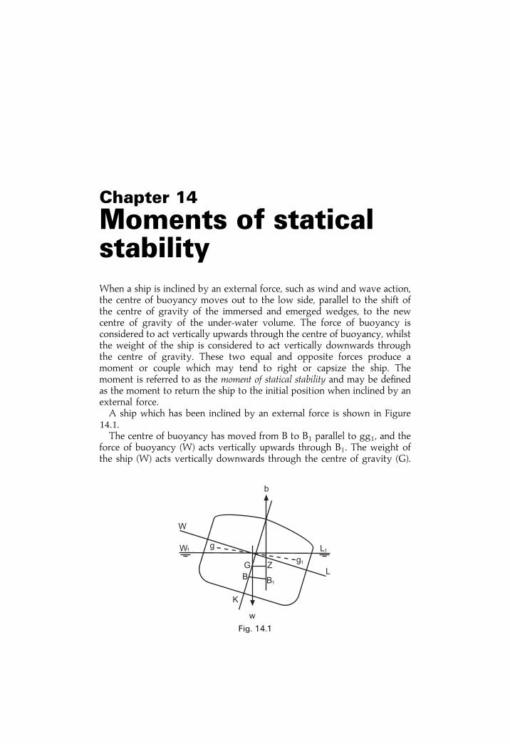
Chapter 14
Moments of staticalstabilityWhen a ship is inclined by an external force, such as wind and wave action,the centre of buoyancy moves out to the low side, parallel to the shift ofthe centre of gravity of the immersed and emerged wedges, to the newcentre of gravity of the under-water volume. The force of buoyancy isconsidered to act vertically upwards through the centre of buoyancy, whilstthe weight of the ship is considered to act vertically downwards throughthe centre of gravity. These two equal and opposite forces produce amoment or couple which may tend to right or capsize the ship. Themoment is referred to as the moment of statical stability and may be de®nedas the moment to return the ship to the initial position when inclined by anexternal force.A ship which has been inclined by an external force is shown in Figure
14.1.The centre of buoyancy has moved from B to B1 parallel to gg1, and the
force of buoyancy (W) acts vertically upwards through B1. The weight ofthe ship (W) acts vertically downwards through the centre of gravity (G).
Fig. 14.1
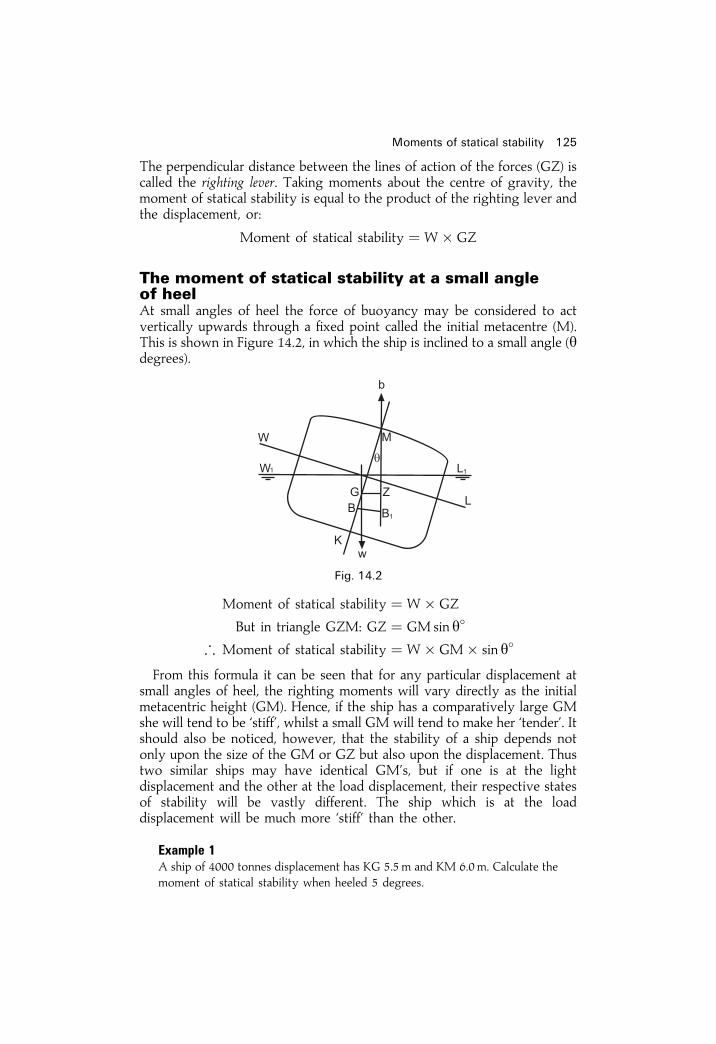
The perpendicular distance between the lines of action of the forces (GZ) iscalled the righting lever. Taking moments about the centre of gravity, themoment of statical stability is equal to the product of the righting lever andthe displacement, or:
Moment of statical stability � W� GZ
The moment of statical stability at a small angleof heelAt small angles of heel the force of buoyancy may be considered to actvertically upwards through a ®xed point called the initial metacentre (M).This is shown in Figure 14.2, in which the ship is inclined to a small angle (ydegrees).
Moment of statical stability � W� GZ
But in triangle GZM: GZ � GMsin y�
; Moment of statical stability � W� GM� sin y�
From this formula it can be seen that for any particular displacement atsmall angles of heel, the righting moments will vary directly as the initialmetacentric height (GM). Hence, if the ship has a comparatively large GMshe will tend to be `stiff', whilst a small GM will tend to make her `tender'. Itshould also be noticed, however, that the stability of a ship depends notonly upon the size of the GM or GZ but also upon the displacement. Thustwo similar ships may have identical GM's, but if one is at the lightdisplacement and the other at the load displacement, their respective statesof stability will be vastly different. The ship which is at the loaddisplacement will be much more `stiff' than the other.
Example 1A ship of 4000 tonnes displacement has KG 5.5m and KM 6.0m. Calculate themoment of statical stability when heeled 5 degrees.
Moments of statical stability 125
Fig. 14.2

GM � KMÿ KG � 6:0ÿ 5:5 � 0:5m
Moment of statical stability � W� GM� sin y�
� 4000� 0:5� sin 5�
Moment of statical stability � 174:4 tonnes m
Example 2When a ship of 12 000 tonnes displacement is heeled 612 degrees the moment ofstatical stability is 600 tonnes m. Calculate the initial metacentric height.
Moment of statical stability � W� GM� sin y�
; GM � Moment of statical stability
W� sin y�
� 600
12 000 sin 6 12�
GM � 0.44m
The moment of statical stability at a large angleof heelAt a large angle of heel the force of buoyancy can no longer be consideredto act vertically upwards through the initial metacentre (M). This is shownin Figure 14.3, where the ship is heeled to an angle of more than 15degrees. The centre of buoyancy has moved further out to the low side, andthe vertical through B1 no longer passes through (M), the initial metacentre.The righting lever (GZ) is once again the perpendicular distance betweenthe vertical through G and the vertical through B1, and the moment ofstatical stability is equal to W�GZ.But GZ is no longer equal to GM sin y�. Up to the angle at which the
126 Ship Stability for Masters and Mates
Fig. 14.3

deck edge is immersed, it may be found by using a formula known as theWall-sided formula. i.e.
GZ � �GM� 12 BM tan2 y� sin y
The derivation of this formula is as follows:
Refer to the ship shown in Figure 14.4. When inclined the wedge WOW1
is transferred to LOL1 such that its centre of gravity shifts from g to g1.This causes the centre of buoyancy to shift from B to B1. The horizontalcomponents of these shifts are hh1 and BB2 respectively, the verticalcomponents being (gh� g1h1) and B1B2 respectively.Let BB2 be `a' units and let B1B2 be `b' units.
Now consider the wedge LOL1:
Area � 12 y
2 tan y
Consider an elementary strip longitudinally of length dx as in Figure14.5(b).
Volume � 12 y
2 tan y dx
The total horizontal shift of the wedge (hh1), is 2=3� 2y or 4=3� y.
; Moment of shifting this wedge � 43 y� 1
2 y2 tan y dx
� 23 y
3 tan y dx
Moments of statical stability 127
y tan i
Fig. 14.4

��� ��� �� �� ���� �� ��� �� � ������ ����
�� �
� � � ��
� � ����
�� �
� ��
�� �� �� �� ���� �� �� ������������� ���� �� ������� ��� �
���
�� �
� ��
� ��� �� �� ���� �� ��� �� � ������ � � � �
��� � �� �� !
��!� ��� � �� ��
��" �� ��� �� �� ����� �� �� ������ � �� ��
� !� ��� � � � �
��� � �
!� �
��� � �# � � $�%
��� ���� �� ���� �� �� ����� � ��� � �
� ���
� ��� ���� �� ���� �� �� ���� � �� ���
� ����
� &����� '()*�+,�� � � �� �� � �
� �
��� ���� ������� �� ������ �� ����
�� ��
���� ����

������ � � ��� �
� �� � �� � ��� �
� ����� �� � � � � �� �� ��� � ��
� ��� �� �� � � ������ ���� � �� �� ��� � ��� �� � ��� �
� �� �� ���� � ��
� � ������ ��� �� �� ��� ��� � � � ����
�� �� ���� � ��
� �� � ���
� �
� � ��� �� �� � � ������ ���� � �� � ���
� �
����
���� � �� ��
���� � � ��
����� � � � ������ ��� �� �� � ����
� �� � � �� � ���
� ���
� � ��� ���
� ��
���� � � ���� �
�!�"
# � ���� �� $��� �%&'(�)
*+ � ,#� �#� �,� ��-� -#� � �,� � ��� �� � ��� �� �* ��� �� � ��� � ��� �� �� � ���� � ��� �� �* ��� � .���� !�" ��� !�"/
� � ��� �� �� � ���� � ��� �� �* ��� �� ��� � �� � �� � ���� �� �*�
*+ � ��� � �* � �� � ���� �� .��� � �0 �� �'�/
������� �� ����� �� ��� ���
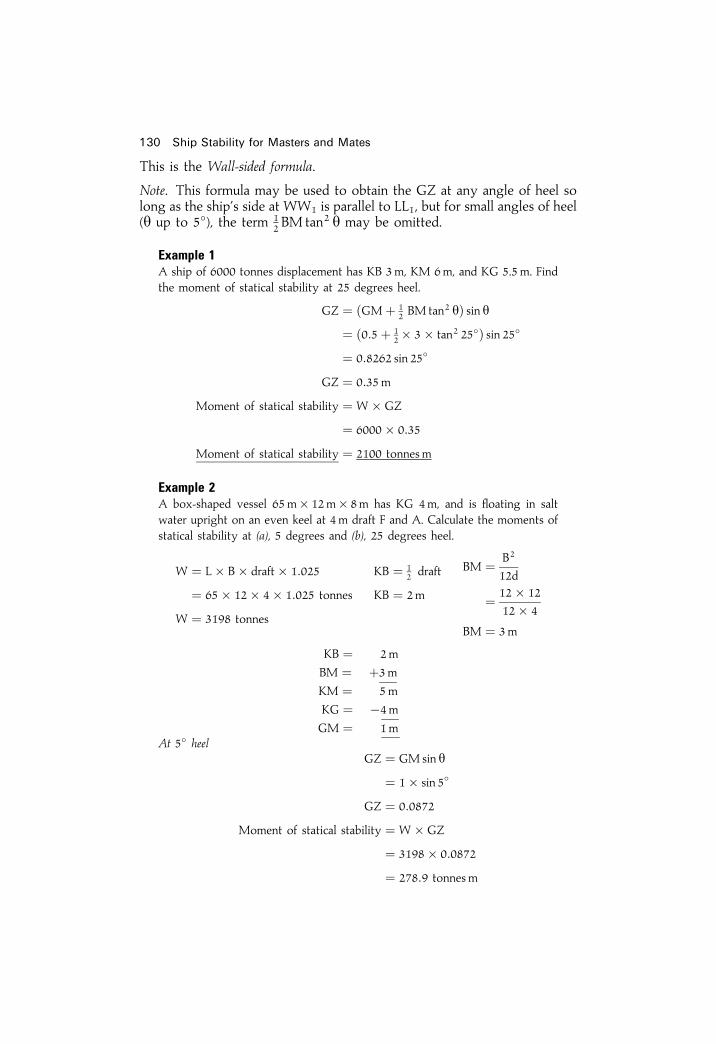
This is the Wall-sided formula.
Note. This formula may be used to obtain the GZ at any angle of heel solong as the ship's side at WW1 is parallel to LL1, but for small angles of heel(y up to 5�), the term 1
2 BM tan2 y may be omitted.
Example 1A ship of 6000 tonnes displacement has KB 3m, KM 6m, and KG 5.5m. Findthe moment of statical stability at 25 degrees heel.
GZ � �GM� 12 BM tan2 y� sin y
� �0:5� 12� 3� tan2 25�� sin 25�
� 0:8262 sin 25�
GZ � 0:35m
Moment of statical stability � W� GZ
� 6000� 0:35
Moment of statical stability � 2100 tonnesm
Example 2A box-shaped vessel 65m� 12m� 8m has KG 4m, and is ¯oating in saltwater upright on an even keel at 4 m draft F and A. Calculate the moments ofstatical stability at (a), 5 degrees and (b), 25 degrees heel.
W � L� B� draft� 1:025
� 65� 12� 4� 1:025 tonnes
W � 3198 tonnes
KB � 12 draft
KB � 2m
BM � B2
12d
� 12� 12
12� 4
BM � 3m
KB � 2m
BM � �3mKM � 5m
KG � ÿ4mGM � 1m
At 5� heelGZ � GMsin y
� 1� sin 5�
GZ � 0:0872
Moment of statical stability � W� GZ
� 3198� 0:0872
� 278:9 tonnes m
130 Ship Stability for Masters and Mates

At 25� heelGZ � �GM� 1
2 BM tan2 y� sin y� �1� 1
2� 3� tan2 25�� sin 25�� �1� 0:3262� sin 25�
� 1:3262 sin 25�
GZ � 0:56 metres
Moment of statical stability � W� GZ
� 3198� 0:56
� 1790:9 tonnesm
Ans. (a) 278.9 tonnesm and (b) 1790.9 tonnes m.The moment of statical stability at a large angle of heel may also be
calculated using a formula known as Attwood's formula: i.e.
Moment of statical stability � W
�v� hh1
Vÿ BG sin y
�The derivation of this formula is as follows:
Moment of statical stability � W� GZ
� W�BRÿ BT�Let v� the volume of the immersed or emerged wedge,hh1 � the horizontal component of the shift of the centre of gravity of the
wedge,V� the underwater volume of the ship, and
Moments of statical stability 131
Fig. 14.6

BR� the horizontal component of the shift of the centre of buoyancy.
BT � BG sin yalso
BR � v� hh1V
; Moment of statical stability � W
�v� hh1
Vÿ BG sin y
�
132 Ship Stability for Masters and Mates
Exercise 14
1 A ship of 10 000 tonnes displacement has GM 0.5m. Calculate the momentof statical stability when the ship is heeled 734 degrees.
2 When a ship of 12 000 tonnes displacement is heeled 514 degrees themoment of statical stability is 300 tonnesm KG 7.5m. Find the height ofthe metacentre above the keel.
3 Find the moment of statical stability when a ship of 10 450 tonnesdisplacement is heeled 6 degrees if the GM is 0.5 m.
4 When a ship of 10 000 tonnes displacement is heeled 15 degrees, therighting lever is 0.2 m, KM 6.8m. Find the KG and the moment of staticalstability.
5 A box-shaped vessel 55m� 7.5 m� 6m has KG 2.7m, and ¯oats in saltwater on an even keel at 4 m draft F and A. Calculate the moments ofstatical stability at (a) 6 degrees heel and (b) 24 degrees heel.
6 A ship of 10 000 tonnes displacement has KG 5.5m, KB 2.8 m, and BM 3m.Calculate the moments of statical stability at (a) 5 degrees heel and (b) 25degrees heel.
7 A box-shaped vessel of 3200 tonnes displacement has GM 0.5m, and beam15m, and is ¯oating at 4m draft. Find the moments of statical stability at 5degrees and 25 degrees heel.
8 A ship of 11 000 tonnes displacement has a moment of statical stability of500 tonnes m when heeled 5 degrees. Find the initial metacentric height.
9 (a) Write a brief description on the characteristics associated with an`Angle of Loll'.
(b) For a box-shaped barge, the breadth is 6.4m and the draft is 2.44meven keel, with a KG of 2.67m.
Using the given wall-sided formula, calculate the GZ ordinates up to anangle of heel of 20�, in 4� increments. From the results construct a StaticalStability curve up to 20� angle of heel. Label the important points on thisconstructed curve.
GZ � sin y�GM� 12 BM tan2 y�

Chapter 15
TrimTrim may be considered as the longitudinal equivalent of list. Trim is alsoknown as `longitudinal stability'. It is in effect transverse stability turnedthrough 90�. Instead of trim being measured in degrees it is measured as thedifference between the drafts forward and aft. If difference is zero then theship is on even keel. If forward draft is greater than aft draft, the vessel istrimming by the bow. If aft draft is greater than the forward draft, the vesselis trimming by the stern.Consider a ship to be ¯oating at rest in still water and on an even keel as
shown in Figure 15.1.The centre of gravity (G) and the centre of buoyancy (B) will be in the
same vertical line and the ship will be displacing her own weight of water.So W � b:Now let a weight `w', already on board, be shifted aft through a distance
`d', as shown in Figure 15.1. This causes the centre of gravity of the ship toshift from G to G1, parallel to the shift of the centre of gravity of theweight shifted, so that:
GG1 � w� d
Wor
W� GG1 � w� d
A trimming moment of W�GG1 is thereby produced.But
W� GG1 � w� d
; The trimming moment � w� d
The ship will now trim until the centres of gravity and buoyancy areagain in the same vertical line, as shown in Figure 15.2. When trimmed, thewedge of buoyancy LFL1 emerges and the wedge WFW1 is immersed.Since the ship, when trimmed, must displace the same weight of water as

when on an even keel, the volume of the immersed wedge must be equal tothe volume of the emerged wedge and F, the point about which the shiptrims, is the centre of gravity of the water-plane area. The point F is calledthe `Centre of Flotation' or `Tipping Centre'.A vessel with a rectangular water-plane has its centre of ¯otation on the
centre line amidships but, on a ship, it may be a little forward or abaftamidships, depending upon the shape of the water-plane. In trim problems,unless stated otherwise, it is to be assumed that the centre of ¯otation issituated amidships.Trimming moments are taken about the centre of ¯otation since this is
the point about which rotation takes place.The longitudinal metacentre (ML) is the point of intersection between the
verticals through the longitudinal positions of the centres of buoyancy. Thevertical distance between the centre of gravity and the longitudinalmetacentre (GML) is called the longitudinal metacentric height.BML is the height of the longitudinal metacentre above the centre of
buoyancy and is found for any shape of vessel by the formula:
BML � ILV
where
IL � the longitudinal second moment of the water-planeabout the centre of flotation
andV � the vessel's volume of displacement
134 Ship Stability for Masters and Mates
Fig. 15.1

The derivation of this formula is similar to that for ®nding the transverseBM.For a rectangular water-plane area:
IL � BL3
12where
L � the length of the water-planeand
B � the breadth of the water-plane
Thus, for a vessel having a rectangular water-plane:
BML � BL3
12VFor a box-shaped vessel:
BML � ILV
� BL3
12V
� BL3
12� L� B� d
BML � L2
12d
Trim 135
Fig. 15.2
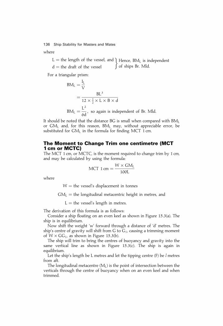
where
L � the length of the vessel, and
d � the draft of the vessel
�Hence, BML is independentof ships Br. Mld.
For a triangular prism:
BML � ILV
� BL3
12� 12� L� B� d
BML � L2
6d; so again is independent of Br. Mld.
It should be noted that the distance BG is small when compared with BML
or GML and, for this reason, BML may, without appreciable error, besubstituted for GML in the formula for ®nding MCT 1 cm.
The Moment to Change Trim one centimetre (MCT1 cm or MCTC)The MCT 1 cm, or MCTC, is the moment required to change trim by 1 cm,and may be calculated by using the formula:
MCT 1 cm � W� GML
100L
where
W � the vessel's displacement in tonnes
GML � the longitudinal metacentric height in metres, and
L � the vessel's length in metres.
The derivation of this formula is as follows:Consider a ship ¯oating on an even keel as shown in Figure 15.3(a). The
ship is in equilibrium.Now shift the weight `w' forward through a distance of `d' metres. The
ship's centre of gravity will shift from G to G1, causing a trimming momentof W�GG1, as shown in Figure 15.3(b).The ship will trim to bring the centres of buoyancy and gravity into the
same vertical line as shown in Figure 15.3(c). The ship is again inequilibrium.Let the ship's length be L metres and let the tipping centre (F) be l metres
from aft.The longitudinal metacentre (ML) is the point of intersection between the
verticals through the centre of buoyancy when on an even keel and whentrimmed.
136 Ship Stability for Masters and Mates
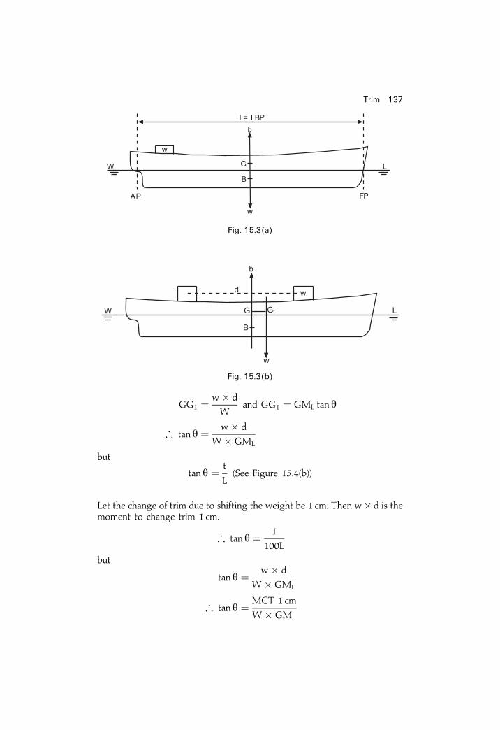
GG1 � w� d
Wand GG1 � GML tan y
; tan y � w� d
W� GML
but
tan y � t
L(See Figure 15.4(b))
Let the change of trim due to shifting the weight be 1 cm. Then w� d is themoment to change trim 1 cm.
; tan y � 1
100L
but
tan y � w� d
W� GML
; tan y � MCT 1 cm
W� GML
Trim 137
Fig. 15.3(a)
Fig. 15.3(b)

orMCT 1 cm
W� GML� 1
100Land
MCT 1 cm � W� GML
100Ltonnesm/cm.
To ®nd the change of draft forward and aft due tochange of trimWhen a ship changes trim it will obviously cause a change in the draftsforward and aft. One of these will be increased and the other decreased. Aformula must now be found which will give the change in drafts due tochange of trim.Consider a ship ¯oating upright as shown in Figure 15.4(a). F1 represents
138 Ship Stability for Masters and Mates
Fig. 15.3(c)
�e�
Fig. 15.4(a)

the position of the centre of ¯otation which is l metres from aft. The ship'slength is L metres and a weight `w' is on deck forward.Let this weight now be shifted aft a distance of `d' metres. The ship will
trim about F1 and change the trim `t' cms by the stern as shown in Figure15.4(b).W1C is a line drawn parallel to the keel.
`A' represents the new draft aft and `F' the new draft forward. The trim istherefore equal to Aÿ F and, since the original trim was zero, this mustalso be equal to the change of trim.Let `x' represent the change of draft aft due to the change of trim and let
`y' represent the change forward.In the triangles WW1F1 and W1L1C, using the property of similar
triangles:x cm
lm� t cm
Lmor
x cm � lm� t cm
Lm
; Change of draft aft in cm � l
L� Change of trim in cm
wherel � the distance of centre of flotation from aft in metres, and
L � the ship's length in metres
It will also be noticed that x� y� t
; Change of draft F in cm � Change of trimÿ Change of draft A:
The effect of shifting weights already on board
Example 1A ship 126m long is ¯oating at drafts of 5.5 m F and 6.5 m A. The centre of¯otation is 3 m aft of amidships. MCT 1 cm� 240 tonnes m. Displacement�
Trim 139
�e�
Fig. 15.4(b)

6000 tonnes. Find the new drafts if a weight of 120 tonnes already on board isshifted forward a distance of 45 metres.
Trimming moment � w� d
� 120� 45
� 5400 tonnes m by the head
Change of trim � Trimming moment
MCT 1 cm
� 5400
240
� 22:5 cm by the head
Change of draft aft � l
L� Change of trim
� 60
126� 22:5
� 10:7 cm
Change of draft forward � 66
126� 22:5
� 11:8 cm
Original drafts 6:500m A 5:500m F
Change due to trim ÿ0:107m �0:118mAns: New drafts 6:393m A 5:618m F
Example 2A box-shaped vessel 90m� 10m� 6m ¯oats in salt water on an even keel at3 m draft F and A. Find the new drafts if a weight of 64 tonnes already onboard is shifted a distance of 40 metres aft.
140 Ship Stability for Masters and Mates
�e�
Fig. 15.5
BML � L2
12d
� 90� 90
12� 3
BML � 225m

W � L� B� d� 1:025
� 90� 10� 3� 1:025
W � 2767:5 tonnes
MCT 1 cm � W� GML
100L
Since BG is small compared with GML:
MCT 1 cm ' W� BML
100L
� 2767:5� 225
100� 90
MCT 1 cm � 69:19 tonnesm/cm
Change of trim � w� d
MCT 1 cm
� 64� 40
69:19
Change of trim � 37 cm by the stern
Change of draft aft � l
L� Change of trim
� 12� 37 cm
Change of draft aft � 18:5 cm
Change of draft forward � 18:5 cm.
Original drafts 3:000m A 3:000m F
Change due to trim �0:185m ÿ0:185mAns: New drafts 3:185m A 2:815m F
The effect of loading and/or discharging weightsWhen a weight is loaded at the centre of ¯otation it will produce notrimming moment, but the ship's drafts will increase uniformly so that theship displaces an extra weight of water equal to the weight loaded. If theweight is now shifted forward or aft away from the centre of ¯otation, itwill cause a change of trim. From this it can be seen that when a weight isloaded away from the centre of ¯otation, it will cause both a bodily sinkageand a change of trim.
Trim 141

Similarly, when a weight is being discharged, if the weight is ®rst shiftedto the centre of ¯otation it will produce a change of trim, and if it is thendischarged from the centre of ¯otation the ship will rise bodily. Thus, botha change of trim and bodily rise must be considered when a weight is beingdischarged away from the centre of ¯otation.
Example 1A ship 90m long is ¯oating at drafts 4.5 m F and 5.0m A. The centre of¯otation is 1.5 m aft of amidships. TPC 10 tonnes. MCT 1 cm. 120 tonnes m.Find the new drafts if a total weight of 450 tonnes is loaded in a position 14mforward of amidships.
Bodily sinkage � w
TPC
� 450
10
Bodily sinkage � 45 cm
Change of trim � Trim moment
MCT 1 cm
� 450� 15:5
120
Change of trim � 58:12 cm by the head
Change of draft aft � l
L� Change of trim
� 43:5
90� 58:12
Change of draft aft � 28:09 cm
Change of draft forward � 46:5
90� 58:12
Change of draft forward � 30:03 cm
142 Ship Stability for Masters and Mates
�e�
Fig. 15.6

Original drafts 5:000m A 4:500m F
Bodily sinkage �0:450m �0:450m5:450m 4:950m
Change due trim ÿ0:281m �0:300mAns: New drafts 5:169m A 5:250m F
Note. In the event of more than one weight being loaded or discharged, the netweight loaded or discharged is used to ®nd the net bodily increase or decreasein draft, and the resultant trimming moment is used to ®nd the change of trim.Also, when the net weight loaded or discharged is large, it may be necessary
to use the TPC and MCT 1 cm at the original draft to ®nd the approximate newdrafts, and then rework the problem using the TPC and MCT 1 cm for themean of the old and the new drafts to ®nd a more accurate result.
Example 2A box-shaped vessel 40m� 6m� 3m is ¯oating in salt water on an even keelat 2 m draft F and A. Find the new drafts if a weight of 35 tonnes is dischargedfrom a position 6m from forward. MCT 1 cm� 8.4 tonnes m.
TPC � WPA
97:56
� 40� 6
97:56
TPC � 2:46 tonnes
Bodily rise � w
TPC
� 35
2:46
Bodily rise � 14:2 cm
Change of trim � w� d
MCT 1 cm
� 35� 14
8:4
Trim 143
�e�
Fig. 15.7

Change of trim � 58:3 cm by the stern
Change of draft aft � l
L� Change of trim
� 12� 58:3 cm
Change of draft aft � 29:15 cm
Change of draft forward � 12� 58:3
Change of draft forward � 29:15 cm
Original drafts 2:000m A 2:000m F
Bodily rise ÿ0:140m ÿ0:140m1:860m 1:860m
Change due trim �0:290m ÿ0:290mAns: New drafts 2:150m A 1:570m F
Example 3A ship 100m long arrives in port with drafts 3 m F and 4.3 m A. TPC 10tonnes. MCT 1 cm 120 tonnesm. The centre of ¯otation is 3 m aft of amidships.If 80 tonnes of cargo is loaded in a position 24m forward of amidships and 40tonnes of cargo is discharged from 12m aft of amidships, what are the newdrafts?
Cargo loaded 80 tonnes
Cargo discharged 40 tonnes
Net loaded 40 tonnes
Bodily sinkage � w
TPC
� 40
10Bodily sinkage � 4 cm
To ®nd the change of trim take moments about the centre of ¯otation.
144 Ship Stability for Masters and Mates
�e�
Fig. 15.8

������ �� �� � �� �����
�� � ��
� ����
���
������ �� �� � �� �� �� �� ����
������ �� ��� �� � �
�� ������ �� ��
� ��
���� ��
������ �� ��� �� � ���� ��
������ �� ��� ����� � ��
���� ��
������ �� ��� ����� � ����� ��
������� ��� ������ ! ������ "
#����� ��$��� ������� �������
������ ������
������ �%� �� ������� �������
!� � &�� ��� ������ ! ������ "
������� �! ��' �� (��� ���� �� '������� �� ��� �� " ��� ��!) �� � �� ������� �* +� �� ���� * ���� �� ,����� � ���� ��' ) ��� ���� �� ����� �� ������ ��� ���� �� �� ��������� ��% ���� -
&�) � ����* ���� �� ��.�� ��� ����� �� ���� ��' &�) � ����* ���� �� ��.�� ��� ����� �� ���� ��' &�) � ����* ���� �� ��.�� ��� �� �� ���� ��' &�) � ����* ���� �� ��.�� ��� �� �� ���� ��'
�� ��������� �%�$� �� �� � ������-
��� ���� � ��� ����� �� ���� ��' �� ���� � ��� �� �� ���� ��'
"��� �� ��� ��� ����� ��� ��)
���� ���
������ ������ � �� ���� ����� �� ���� � �� ��
��� ���
��� ��� ��(� /��� �� �(� /
���� /

Total cargo discharged 2000 tonnes
Total bunkers loaded 200 tonnes
Net weight discharged 1800 tonnes
Bodily rise � w
TPC
� 1800
20Bodily rise � 90 cm
Assume levers and moments aft of LCF are �ve.Assume levers and moments forward of LCF are ÿve.
Resultant moment 3550 tonnes m by the head because of the ÿve sign.
Change of trim � Trim moment
MCT 1 cm
� 3550
100
Change of trim � 35:5 cm by the head
Since centre of ¯otation is amidships,
Change of draft aft � Change of draft forward
� 12 change of trim
146 Ship Stability for Masters and Mates
�e�
Fig. 15.9
Weight Distance from C.F. Moments
ÿ500 ÿ40 �20 000ÿ500 ÿ25 �12 500ÿ500 �20 ÿ10 000ÿ500 �50 ÿ25 000�150 ÿ12 ÿ1800�50 �15 �750
ÿ3550

� 17:75 cm say 0.18m
Original drafts 8:000m A 7:000m F
Bodily rise ÿ0:900m ÿ0:900m7:100m 6:100m
Change due trim ÿ0:180m �0:180mAns: New drafts 6:920m A 6:280m F
Example 5A ship arrives in port trimmed 25 cm by the stern. The centre of ¯otation isamidships. MCT 1 cm 100 tonnes m. A total of 3800 tonnes of cargo is to bedischarged from 4 holds, and 360 tonnes of bunkers loaded in No. 4 doublebottom tank. 1200 tonnes of the cargo is to be discharged from No. 2 hold and600 tonnes from No. 3 hold. Find the amount to be discharged from Nos. 1 and4 holds if the ship is to complete on an even keel.
Centre of gravity of No. 1 hold is 50m forward of the centre of flotationCentre of gravity of No. 2 hold is 30m forward of the centre of flotationCentre of gravity of No. 3 hold is 20m abaft of the centre of flotationCentre of gravity of No. 4 hold is 45m abaft of the centre of flotationCentre of gravity of No. 4 DB tank is 5 m abaft of the centre of flotation
Total cargo to be discharged from 4 holds 3800 tonnes
Total cargo to be discharged from Nos. 2 and 3 1800 tonnes
Total cargo to be discharged from Nos. 1 and 4 2000 tonnes
Let `x' tonnes of cargo be discharged from No. 1 holdLet (2000ÿ x) tonnes of cargo be discharged from No. 4 hold
Take moments about the centre of ¯otation, or as shown in Figure 15.10.
Original trim � 25 cm by the stern, i.e.� 25 cm
Required trim � 0
Change of trim required � 25 cm by the head, i.e.ÿ 25 cm
Trim 147
�e�
Fig. 15.10

Trimming moment required � Change of trim�MCT 1 cm
� ÿ25� 100 � ÿ2500Trimming moment required � 2500 tonnesm by the head
Resultant moment � Moment to change trim by headÿMCT by stern
; ÿ 2500 � ÿ102 000� 45x� 37 800� 50x
� ÿ102 000� 45x� 37 800� 50 x
� 64 200ÿ 95xor
95x � 61 700
x=649.5 tonnesand
2000ÿ x � 1350:5 tonnes
Ans. Discharge 649.5 tonnes from No. 1 hold and 1350.5 tonnes from No. 4hold.
Using trim to ®nd the position of the centreof ¯otation
ExampleA ship arrives in port ¯oating at drafts of 4.50m A and 3.80m F. The followingcargo is then loaded:
100 tonnes in a position 24m aft of amidships
30 tonnes in a position 30m forward of amidships
60 tonnes in a position 15m forward of amidships
The drafts are then found to be 5.10m A and 4.40m F. Find the position of thelongitudinal centre of ¯otation aft of amidships.Original drafts 4.50m A 3.80m F give 0.70m trim by the stern, i.e. �70 cm.New drafts 5.10m A 4.40m F give 0.70m trim by the stern, i.e. �70 cm.Therefore there has been no change in trim, which means that
148 Ship Stability for Masters and Mates
Weight Distance from MomentsC.F.
ÿve �veÿx ÿ50 ± �50xÿ1200 ÿ30 ± �36 000ÿ600 �20 ÿ12 000 ±ÿ�2000ÿ x� �45 ÿ�90 000ÿ 45x� ±�360 �5 ± �1800
ÿ102 000� 45x �37 800� 50x

The moment to change trim by the head� The moment to change trim by thestern.Let the centre of ¯otation be `x' metres aft of amidships. Taking moments,
then,100�24ÿ x� � 30�30� x� � 60�15� x�2400ÿ 100x � 900� 30x� 900� 60x
190x � 600
x � 3:16m
Ans. Centre of flotation is 3.16 metres aft of amidships.Note. In this type of question it is usual to assume that the centre of ¯otation isaft of amidships, but this may not be the case. Had it been assumed that thecentre of ¯otation was aft of amidships when in actual fact it was forward, thenthe answer obtained would have been minus.Remember. Levers, moments and trim by the stern all have a �ve sign. Levers,moments and trim by the head all have a ÿve sign.
Loading a weight to keep the after draft constantWhen a ship is being loaded it is usually the aim of those in charge of theoperation to complete loading with the ship trimmed by the stern. Shouldthe ship's draft on sailing be restricted by the depth of water over a dock-sill or by the depth of water in a channel, then the ship will be loaded insuch a manner as to produce this draft aft and be trimmed by the stern.Assume now that a ship loaded in this way is ready to sail. It is then
found that the ship has to load an extra weight. The weight must be loadedin such a position that the draft aft is not increased and also that themaximum trim is maintained.lf the weight is loaded at the centre of ¯otation, the ship's drafts will
increase uniformly and the draft aft will increase by a number of centimetresequal to w/TPC. The draft aft must now be decreased by this amount.Now let the weight be shifted through a distance of `d' metres forward.
The ship will change trim by the head, causing a reduction in the draft aftby a number of centimetres equal to l/L�Change of trim.Therefore, if the same draft is to be maintained aft, the above two
quantities must be equal. i.e.
Trim 149
�e�
Fig. 15.11

l
L� Change of trim � w
TPCSo,
Change of trim � w
TPC� L
l�I�
But,
Change of trim � w� d
MCT 1 cm�II�
Equate (I) and (II)
;w� d
MCT 1 cm� w
TPC� L
l
or
d � L�MCT 1 cm
l� TPC
where d� the distance forward of the centre of ¯otation to load a weightto keep the draft aft constant,
L� the ship's length, LBP andl � the distance of the centre of ¯otation to the stern.
ExampleA box-shaped vessel 60m long, 10m beam, and 6m deep, is ¯oating in saltwater at drafts 4m F and 4.4 m A. Find how far forward of amidships a weightof 30 tonnes must be loaded if the draft aft is to remain at 4.4 m.
TPCSW � WPA
97:56
� 60� 10
97:56
TPCSW � 6:15 tonnes
W � L� B� d� rSW tonnes
� 60� 10� 4:2� 1:025
W � 2583 tonnes
BML � L2
12d
� 60� 60
12� 4:2
BML � 71:42 metres
MCT 1 cm ' W� BML
100Lbecause GML ' BML
150 Ship Stability for Masters and Mates

MCT 1 cm � 2583� 71:42
100� 60
MCT 1 cm � 30:75 t m/cm
d � L�MCT 1 cm
l� TPCSW
� 60
30� 30:75� 1
6:15
d � 10 metres from LCF
LCF is at amidships.Ans. Load the weight 10 metres forward of amidships.
Loading a weight to produce a required draft
ExampleA ship 150 metres long arrives at the mouth of a river with drafts 5.5m Fand 6.3 m A. MCT 1 cm 200 tonnes m. TPC 15 tonnes. Centre of ¯otation is1.5 m aft of amidships. The ship has then to proceed up the river where themaximum draft permissible is 6.2 m. It is decided that SW ballast will be runinto the forepeak tank to reduce the draft aft to 6.2 m. If the centre of gravityof the forepeak tank is 60 metres forward of the centre of ¯otation, ®nd theminimum amount of water which must be run in and also ®nd the ®nal draftforward.
(a) Load `w' tonnes at the centre of ¯otation.
Bodily sinkage � w
TPC
� w
15cm
New draft aft � 6:3m� w
15cm �I�
Trim 151
�e�
Fig. 15.12

Required draft aft � 6:2m �II�
Equations (I)N(II) � Reduction required � 0:1m� w
15cm
� 10 cm� w
15cm
��10� w
15
�cm �III�
(b) Shift `w' tonnes from the centre of ¯otation to the forepeak tank
Change of trim � w� d
MCT 1 cm
� 60w
200
Change of trim � 3w
10cm by the head
Change of draft aft due to trim � l
L� Change of trim
� 73:5
150� 3w
10
Change of draft aft due to trim � 0:147w cm �IV�
But change of draft required aft ��10� w
15
�cm as per equation (III)
0:147w � 10� w
15; i.e. equation (IV) � equation (III).
2:205w � 150� w
1:205w � 150
w � 124:5 tonnes
Therefore by loading 124.5 tonnes in the forepeak tank the draft aft will bereduced to 6.2 metres.
(c) To ®nd the new draft forward
Bodily sinkage � w
TPC
� 124.5
15
152 Ship Stability for Masters and Mates

Bodily sinkage � 8:3 cm
Change of trim � w� d
MCT 1 cm
� 124:5� 60
200
Change of trim � 37:35 cm by the head
Change of draft aft due trim � l
L� Change of trim
Change of draft aft due trim � 73:5
150� 37:35
� 18:3 cm
Change of draft forward due trim � Change of trimÿ Change of draft aft
� 37:35ÿ 18:3 cm � 19:05 cm; or
Change of draft forward due trim � 76:5� 37:35
150� 19:05 cm
Original drafts 6:300m A 5:500m F
Bodily sinkage �0:080m �0:080m6:380m 5:580m
Change due trim ÿ0:180m �0:190mNew drafts 6:200m A 5:770m F
Ans. Load 124.5 tonnes in forepeak tank. Final draft forward is 5.770 metres.
Using change of trim to ®nd the longitudinalmetacentric height (GML)Earlier it was shown in this chapter that, when a weight is shiftedlongitudinally within a ship, it will cause a change of trim. It will now beshown how this effect may be used to determine the longitudinalmetacentric height.Consider Figure 15.13(a) which represents a ship of length `L' at the
waterline, ¯oating upright on an even keel with a weight on deck forward.The centre of gravity is at G, the centre of buoyancy at B, and thelongitudinal metacentre at ML. The longitudinal metacentric height istherefore GML.Now let the weight be shifted aft horizontally as shown in Figure
15.13(b). The ship's centre of gravity will also shift horizontally, from G toG1, producing a trimming moment of W�GG1 by the stern.The ship will now trim to bring G1 under ML as shown in Figure 15.13(c).In Figure 15.13(c) W1L1 represents the new waterline, F the new draft
forward, and A the new draft aft. It was shown in Figure 15.4(b) and by the
Trim 153

154 Ship Stability for Masters and Mates
Fig. 15.13(a)
Fig. 15.13(b)
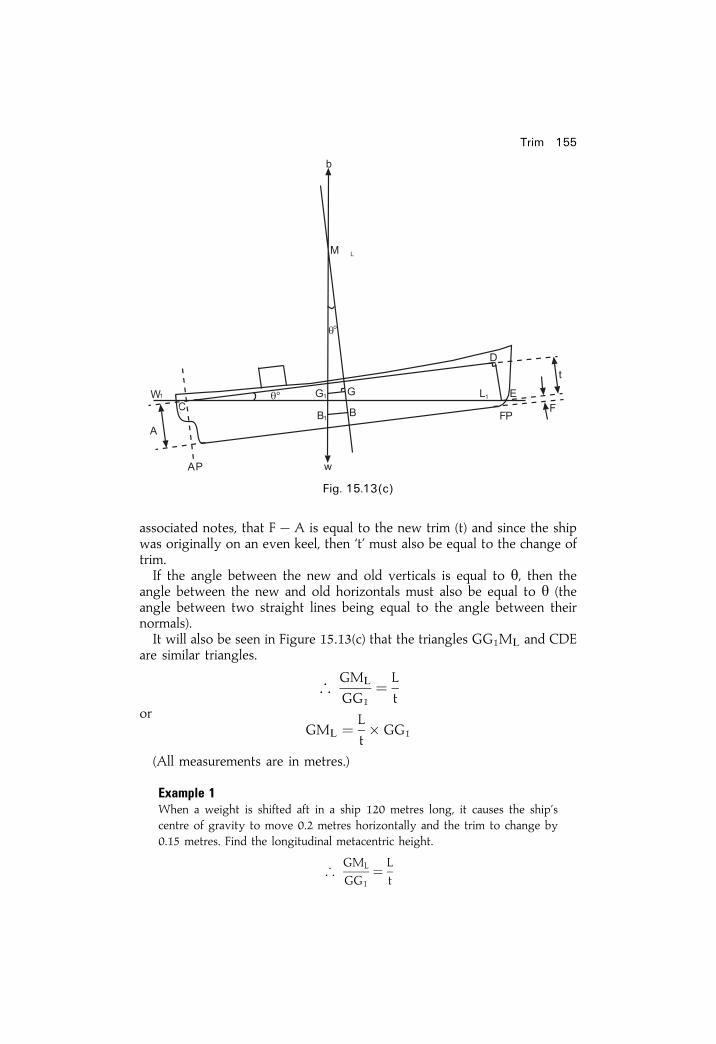
associated notes, that Fÿ A is equal to the new trim (t) and since the shipwas originally on an even keel, then `t' must also be equal to the change oftrim.If the angle between the new and old verticals is equal to y, then the
angle between the new and old horizontals must also be equal to y (theangle between two straight lines being equal to the angle between theirnormals).It will also be seen in Figure 15.13(c) that the triangles GG1ML and CDE
are similar triangles.
;GML
GG1� L
tor
GML � L
t� GG1
(All measurements are in metres.)
Example 1When a weight is shifted aft in a ship 120 metres long, it causes the ship'scentre of gravity to move 0.2 metres horizontally and the trim to change by0.15 metres. Find the longitudinal metacentric height.
;GML
GG1� L
t
Trim 155
Fig. 15.13(c)

; GML � L
t� GG1
� 120� 0:2
0:15
Ans. GML � 160 metres
Example 2A ship 150 metres long has a displacement of 7200 tonnes, and is ¯oatingupright on an even keel. When a weight of 60 tonnes, already on board, isshifted 24 metres forward, the trim is changed by 0.15 metres. Find thelongitudinal metacentric height.
GML
GG1� L
t
GML � GG1 � L
t
� w� d
W� L
t
� 60� 24
7200� 150
0:15
Ans. GML � 200 metres
Summary1 Make a sketch from the given information.2 Estimate the mean bodily sinkage.3 Calculate the change of trim using levers measured from LCF.4 Evaluate the trim ratio forward and aft at FP and AP, from the LCFposition.
5 Collect the above calculated values to estimate the ®nal end drafts.6 In the solutions shown in the text, these ®nal end drafts have beencalculated to three decimal ®gures. In practice, naval architects and ship-of®cers round off the drafts to two decimal places only. This givesacceptable accuracy.
7 Note how the formulae were written in letters ®rst and then put the ®guresin. In the event of a mathematical error, marks will be given for a correctformula and for a correct sketch.
156 Ship Stability for Masters and Mates

Trim 157
EXERCISE 15
1 A ship of 8500 tonnes displacement has TPC 10 tonnes, MCT 1 cm� 100tonnesm and the centre of ¯otation is amidships. She is completingloading under coal tips. Nos. 2 and 3 holds are full, but space is availablein No. 1 hold (centre of gravity 50m forward of amidships), and in No. 4hold (centre of gravity 45m aft of amidships). The present drafts are 6.5mF and 7m A, and the load draft is 7.1m. Find how much cargo is to beloaded in each of the end holds so as to put the ship down to the loaddraft and complete loading on an even keel.
2 An oil tanker 150m long, displacement 12 500 tonnes, MCT 1 cm 200tonnesm, leaves port with drafts 7.2 m F and 7.4 m A. There is 550 tonnesof fuel oil in the foward deep tank (centre of gravity 70m forward of thecentre of ¯otation) and 600 tonnes in the after deep tank (centre of gravity60m aft of centre of ¯otation). The centre of ¯otation is 1 m aft ofamidships. During the sea passage 450 tonnes of oil is consumed from aft.Find how much oil must be transferred from the forward tank to the aftertank if the ship is to arrive on an even keel.
3 A ship 100m long, and with a displacement of 2200 tonnes, haslongitudinal metacentric height 150m. The present drafts are 5.2 m Fand 5.3m A. Centre of ¯otation is 3 m aft of amidships. Find the newdrafts if a weight of 5 tonnes already on board is shifted aft through adistance of 60 metres.
4 A ship is ¯oating at drafts of 6.1 metres F and 6.7 metres A. The followingcargo is then loaded:
20 tonnes in a position whose centre of gravity is 30 metresforward of amidships.45 tonnes in a position whose centre of gravity is 25 metresforward of amidships.60 tonnes in a position whose centre of gravity is 15 metresaft of amidships.30 tonnes in a position whose centre of gravity is 3 metresaft of amidships.
The centre of ¯otation is amidships, MCT 1 cm� 200 tonnes m, andTPC� 35 tonnes. Find the new drafts forward and aft.
5 A ship arrives in port trimmed 0.3 m by the stern and is to discharge 4600tonnes of cargo from 4 holds. 1800 tonnes of the cargo is to be dischargedfrom No. 2 and 800 tonnes from No. 3 hold. Centre of ¯otation isamidships, MCT 1 cm� 250 tonnes m.
The centre of gravity of No. 1 hold is 45m forward of amidships.
The centre of gravity of No. 2 hold is 25m forward of amidships.
The centre of gravity of No. 3 hold is 20m aft of amidships.
The centre of gravity of No. 4 hold is 50m aft of amidships.

158 Ship Stability for Masters and Mates
Find the amount of cargo which must be discharged from Nos. 1 and 4holds if the ship is to sail on an even keel.
6 A ship is 150m long, displacement 12 000 tonnes, and is ¯oating at draftsof 7 m F and 8m A. The ship is to enter port from an anchorage with amaximum draft of 7.6 m. Find the minimum amount of cargo to dischargefrom a hold whose centre of gravity is 50m aft of the centre of ¯otation(which is amidships), TPC 15 tonnes, and MCT 1 cm� 300 tonnes m.
7 A ship 150m� 20m ¯oats on an even keel at 10m draft and has a blockcoef®cient of ®neness 0.8 and LGM of 200 metres. If 250 tonnes of cargois discharged from a position 32m from the centre of ¯otation, ®nd theresulting change of trim.
8 A ship is ¯oating in salt water at drafts of 6.7 m F and 7.3m A. MCT1 cm� 250 tonnesm. TPC 10 tonnes. Length of ship 120 metres. Thecentre of ¯otation is amidships. 220 tonnes of cargo is then dischargedfrom a position 24m forward of the centre of ¯otation. Find the weight ofcargo which must now be shifted from 5m aft of the centre of ¯otation toa position 20m forward of the centre of ¯otation, to bring the draft aft to7 metres. Find also the ®nal draft forward.
9 A ship ¯oats in salt water on an even keel displacing 6200 tonnes.KG� 5.5m, KM� 6.3 m, and there is 500 tonnes of cargo yet to load.Space is available in No. 1 `tween deck (KG 7.6m, centre of gravity 40mforward of the centre of ¯otation) and in No. 4 lower hold (KG 5.5 m,centre of gravity 30m aft of the centre of ¯otation). Find how much cargoto load in each space to complete loading trimmed 0.6 m by the stern, and®nd also the ®nal GM. MCT 1 cm� 200 tonnes m.
10 A ship, ¯oating at drafts of 7.7 m F and 7.9 m. A sustains damage in anend-on collision and has to lift the bow to reduce the draft forward to6.7 m. The ship is about to enter a port in which the maximum permissibledraft is 8.3 m. To do this it is decided to discharge cargo from No. 1 hold(centre of gravity 75m forward of amidships) and No. 4 hold (centre ofgravity 45m aft of amidships). MCT 1 cm 200 tonnesm, TPC 15 tonnes.Centre of ¯otation is amidships. Find the minimum amount of cargo todischarge from each hold.
11 A ship 100m long has centre of ¯otation 3m aft of amidships and is¯oating at drafts 3.2 m F and 4.4m A. TPC 10 tonnes. MCT 1 cm� 150tonnes m. 30 tonnes of cargo is then discharged from 20m forward ofamidships and 40 tonnes is discharged from 12m aft of amidships. Findthe ®nal drafts.
12 A ship 84 metres long is ¯oating on an even keel at a draft of 5.5 metres.45 tonnes of cargo is then loaded in a position 30m aft of amidships. Thecentre of ¯otation is 1 m aft of amidships. TPC 15 tonnes. MCT1 cm� 200 tonnesm. Find the ®nal drafts.
13 A ship arrives in port with drafts 6.8 m. F and 7.2 m A. 500 tonnes ofcargo is then discharged from each of 4 holds.
Trim 159
The centre of gravity of No. 1 hold is 40m forward of amidshipsThe centre of gravity of No. 2 hold is 25m forward of amidshipsThe centre of gravity of No. 3 hold is 20m aft of amidshipsThe centre of gravity of No. 4 hold is 50m aft of amidships
Also 50 tonnes of cargo is loaded in a position whose centre of gravity is15m aft of amidships, and 135 tonnes of cargo centre of gravity 40mforward of amidships. TPC� 15 tonnes. MCT 1 cm� 400 tonnes m. Thecentre of ¯otation is amidships. Find the ®nal drafts.
Using trim to ®nd the position of the centre of ¯otation
14 A ship is ¯oating at drafts 5.5 m F and 6.0 m A. The following cargo isthen loaded:
97 tonnes centre of gravity 8m forward of amidships20 tonnes centre of gravity 40m aft of amidships28 tonnes centre of gravity 20m aft of amidships
The draft is now 5.6 metres F and 6.1 metres A. Find the position of thecentre of ¯otation relative to amidships.
15 Find the position of the centre of ¯otation of a ship if the trim remainsunchanged after loading the following cargo:
100 tonnes centre of gravity 8 metres forward of amidships20 tonnes centre of gravity 40 metres aft of amidships28 tonnes centre of gravity 20 metres aft of amidships
16 A ship arrives in port with drafts 6.8 m F and 7.5 m A. The followingcargo is discharged:
90 tonnes centre of gravity 30m forward of amidships40 tonnes centre of gravity 25m aft of amidships50 tonnes centre of gravity 50m aft of amidships
The drafts are now 6.7 m F and 7.4 m A. Find the position of the centre of¯otation relative to amidships.
Loading a weight to keep a constant draft aft
17 A ship is 150m long, MCT 1 cm 400 tonnesm, TPC 15 tonnes. Thecentre of ¯otation is 3 m aft of amidships. Find the position in which toload a mass of 30 tonnes, with reference to the centre of ¯otation, so as tomaintain a constant draft aft.
18 A ship 120 metres long, with maximum beam 15m, is ¯oating in saltwater at drafts 6.6 m F and 7m A. The block coef®cient and coef®cient of®neness of the water-plane is 0.75. Longitudinal metacentric height 120m.Centre of ¯otation is amidships. Find how much more cargo can be loadedand in what position relative to amidships if the ship is to cross a bar witha maximum draft of 7 m F and A.
Loading a weight to produce a required draft
19 A ship 120m long ¯oats in salt water at drafts 5.8 m F and 6.6 m A. TPC15 tonnes. MCT 1 cm� 300 tonnesm. Centre of ¯otation is amidships.

160 Ship Stability for Masters and Mates
What is the minimum amount of water ballast required to be taken intothe forepeak tank (centre of gravity 60m forward of the centre of¯otation) to reduce the draft aft to 6.5 metres? Find also the ®nal draftforward.
20 A ship leaves port with drafts 7.6 m F and 7.9m A. 400 tonnes of bunkersare burned from a space whose centre of gravity is 15m forward of thecentre of ¯otation, which is amidships. TPC 20 tonnes. MCT 1 cm� 300tonnes m. Find the minimum amount of water which must be run into theforepeak tank (centre of gravity 60m forward of the centre of ¯otation) inorder to bring the draft aft to the maximum of 7.7 m. Find also the ®naldraft forward.
21 A ship 100m long has MCT 1 cm 300 tonnes-m requires 1200 tonnes ofcargo to complete loading and is at present ¯oating at drafts of 5.7 m Fand 6.4 m A. She loads 600 tonnes of cargo in a space whose centre ofgravity is 3m forward of amidships. The drafts are then 6.03m F and6.67m A. The remainder of the cargo is to be loaded in No. 1 hold (centreof gravity 43m forward of amidships) and in No. 4 hold (centre of gravity37m aft of amidships). Find the amount which must be loaded in eachhold to ensure that the draft aft will not exceed 6.8 metres. LCF is atamidships.
22 A ship 100 metres long is ¯oating in salt water at drafts 5.7m F and 8mA. The centre of ¯otation is 2m aft of amidships. Find the amount ofwater to run into the forepeak tank (centre of gravity 48m forward ofamidships) to bring the draft aft to 7.9 m. TPC 30 tonnes. MCT1 cm� 300 tonnesm.
23 A ship 140m long arrives off a port with drafts 5.7m F and 6.3m A. Thecentre of ¯otation is 3 m aft of amidships. TPC 30 tonnes. MCT1 cm� 420 tonnes m. It is required to reduce the draft aft to 6.2m byrunning water into the forepeak tank (centre of gravity 67m forward ofamidships). Find the minimum amount of water to load and also give the®nal draft forward.
Using change of trim to ®nd GML
24 A ship 150m long is ¯oating upright on an even keel. When a weightalready on board is shifted aft, it causes the ship's centre of gravity to shift0.2 m horizontally and the trim to change by 0.15m. Find the longitudinalmetacentric height.
25 A ship of 5000 tonnes displacement is 120m long and ¯oats upright on aneven keel. When a mass of 40 tonnes, already on board, is shifted 25mforward horizontally, it causes the trim to change by 0.1m. Find thelongitudinal metacentric height.
26 A ship is 130m LBP and is loaded ready for departure as shown in thetable below. From her Hydrostatic Curves at 8 m even-keel draft in saltwater it is found that: MCTC is 150 tm/cm. LCF is 2.5 m forward �e�, W is12 795 tonnes and LCB is 2m for'd �e�. Calculate the ®nal end drafts for

Trim 161
this vessel. What is the ®nal value for the trim? What is the Dwt value forthis loaded condition?
Item Weight in tonnes LCG from amidships
Lightweight 3600 2.0 m aftCargo 8200 4.2 m forwardOil Fuel 780 7.1 m aftStores 20 13.3 m forwardFresh Water 100 20.0 m aftFeed Water 85 12.0 m aftCrew and Effects 10 at amidships

Chapter 16
Stability andhydrostatic curves1. Cross Curves of Stability
(a) GZ Cross Curves of StabilityThese are a set of curves from which the righting lever about an assumedcentre of gravity for any angle of heel at any particular displacement maybe found by inspection. The curves are plotted for an assumed KG and, ifthe actual KG of the ship differs from this, a correction must be applied tothe righting levers taken from the curves.Figure 16.1 shows a set of Stability Cross Curves plotted for an
imaginary ship called M.V. `Tanker', assuming the KG to be 9 metres. Ascale of displacements is shown along the bottom margin and a scale ofrighting levers (GZs) in metres on the left-hand margin. The GZ scaleextends from �4:5m through 0 to ÿ1 metre. The curves are plotted at 15degree intervals of heel between 15 degrees and 90 degrees.To ®nd the GZs for any particular displacement locate the displacement
concerned on the bottom scale and, through this point erect a perpendicularto cut all the curves. Translate the intersections with the curves horizontallyto the left-hand scale and read off the GZs for each angle of heel.
Example 1Using the Stability Cross Curves for M.V. 'Tanker' ®nd the GZs at 15-degreeintervals between 0 degrees and 90 degrees heel when the displacement is35 000 tonnes, and KG� 9 metres.Erect a perpendicular through 35 000 tonnes on the displacement scale and
read off the GZs from the left-hand scale as follows:
Angle of heel 0� 15� 30� 45� 60� 75� 90�
GZ in metres 0 0.86 2.07 2.45 1.85 0.76 ÿ0:5Should the KG of the ship be other than 9 metres, a correction must be
applied to the GZs taken from the curves to obtain the correct GZs. Thecorrections are tabulated in the block at the top right-hand side of Figure 16.1

Fig. 16.1

and are given for each one metre difference between 9 metres and the ship'sactual KG. To ®nd the correction to the GZ, multiply the correction taken fromthe table for the angle of heel concerned, by the difference in KGs. To apply thecorrection: when the ship's KG is greater than 9 metres the ship is less stable andthe correction must be subtracted, but when the KG is less than 9 metres the shipis more stable and the correction is to be added.
The derivation of the table is as follows:In Figure 16.2(a), KG is 9m, this being the KG for which this set of curves is
plotted, and GZ represents the righting lever, as taken from the curves for thisparticular angle of heel.Consider the case when the KG is greater than 9m (KG1 in Figure 16.2(a)).
The righting lever is reduced to G1Z1. Let G1X be perpendicular to GZ. Then
G1Z1 � XZ
� GZÿ GXor
Corrected GZ � Tabulated GZÿ Correction
Also, in triangle GXG1:
GX � GG1 sin y�
orCorrection � GG1 sin y
� where y� is the angle of heel.
But GG1 is the difference between 9m and the ship's actual KG. Therefore, thecorrections shown in the table on the Cross Curves for each one metredifference of KG are simply the Sines of the angle of heel.Now consider the case where KG is less than 9m (KG2 in Figure 16.2(b)).
The length of the righting lever will be increased to G2Z2.Let GY be perpendicular to G2Z2 then
G2Z2 � YZ2 � G2Y
164 Ship Stability for Masters and Mates
Fig. 16.2(a)

butYZ2 � GZ
thereforeG2Z2 � GZ� G2Y
orCorrected GZ � Tabulated GZ� Correction
Also, in triangle GG2Y:
G2Y � GG2 sin y�
orCorrection � GG2 sin heel
It will be seen that this is similar to the previous result except that in this casethe correction is to be added to the tabulated GZ.
Example 2Using the Stability Cross Curves for M.V. `Tanker', ®nd the GZs at 15-degreeintervals between 0 degrees and 90 degrees when the displacement is 38 000tonnes and the KG is 8.5 metres.
Stability and hydrostatic curves 165
Fig. 16.2(b)
Heel Tabulated GZ Correction Correct GZ(KG 9m) (GG1 sin y
�) (KG 8.5 m)
0� 0 0.5� 0 � 0 0 � 0 � 015� 0.81 0.5� 0.259 � 0:129 0.81� 0.13 � 0:9430� 1.90 0.5� 0.5 � 0:250 1.90� 0.25 � 2:1545� 2.24 0.5� 0.707 � 0:353 2.24� 0.35 � 2:5960� 1.70 0.5� 0.866 � 0:433 1.70� 0.43 � 2:1375� 0.68 0.5� 0.966 � 0:483 0.68� 0.48 � 1:1690� ÿ0.49 0.5� 1.000 � 0:500 ÿ0.49� 0.50 � 0:01
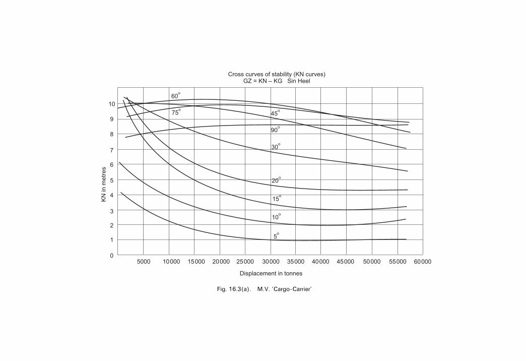
Fig. 16.3(a). M.V. `Cargo-Carrier'

KN Cross Curves of StabilityIt has already been shown that the Stability Cross Curves for a ship areconstructed by plotting the righting levers for an assumed height of thecentre of gravity above the keel. In some cases the curves are constructedfor an assumed KG of zero. The curves are then referred to as KN curves,KN being the righting lever measured from the keel. Figure 16.3(a) showsthe KN curves for an imaginary ship called the M.V. `Cargo-Carrier'.
To obtain the righting levers for a particular displacement and KG thevalues of KN are ®rst obtained from the curves by inspection at thedisplacement concerned. The correct righting levers are then obtained bysubtracting from the KN values a correction equal to the product of the KGand sin Heel.In Figure 16.3(b), let KN represent the ordinate obtained from the curves.
Also, let the ship's centre of gravity be at G so that KG represents theactual height of the centre of gravity above the keel and GZ represents thelength of the righting lever.Now
GZ � XN
� KNÿ KXor
GZ � KNÿ KG sin y
Thus, the righting lever is found by always subtracting from the KNordinate a correction equal to KG sin heel.
Stability and hydrostatic curves 167
Fig. 16.3(b)

Example 3Find the righting levers for M.V. `Cargo-Carrier' when the displacement is40 000 tonnes and the KG is 10 metres.
2. Statical Stability curvesThe curve of statical stability for a ship in any particular condition ofloading is obtained by plotting the righting levers against angle of heel asshown in Figures 16.4 and 16.5.
From this type of graph a considerable amount of stability informationmay be found by inspection:The range of stability. This is the range over which the ship has positive
righting levers. In Figure 16.4 the range is from 0 degrees to 86 degrees.The angle of vanishing stability. This is the angle of heel at which the
righting lever returns to zero, or is the angle of heel at which the sign of the
168 Ship Stability for Masters and Mates
Heel �y� KN sin y KG sin y GZ� KNÿ KG sin y
5� 0.90 0.087 0.87 0.0310� 1.92 0.174 1.74 0.1815� 3.11 0.259 2.59 0.5220� 4.25 0.342 3.42 0.8330� 6.30 0.500 5.00 1.3045� 8.44 0.707 7.07 1.3760� 9.39 0.866 8.66 0.7375� 9.29 0.966 9.66 ÿ 0.3790� 8.50 1.000 10.00 ÿ 1.50
Fig. 16.4. Curve for a ship with positive initial metacentric height.

righting levers changes from positive to negative. The angle of vanishingstability in Figure 16.4 is 86 degrees.The maximum GZ is obtained by drawing a tangent to the highest point
in the curve. In Figure 16.4, AB is the tangent and this indicates a maximumGZ of 0.63 metres. If a perpendicular is dropped from the point oftangency, it cuts the heel scale at the angle of heel at which the maximumGZ occurs. In the present case the maximum GZ occurs at 42 degrees heel.The initial metacentric height (GM) is found by drawing a tangent to the
curve through the origin (OX in Figure 16.4), and then erecting aperpendicular through an angle of heel of 57.3 degrees. Let the two linesintersect at Y. Then the height of the intersection above the base (YZ),when measured on the GZ scale, will give the initial metacentric height. Inthe present example the GM is 0.54 metres.Figure 16.5 shows the stability curve for a ship having a negative initial
metacentric height. At angles of heel of less than 18 degrees the rightinglevers are negative, whilst at angles of heel between 18 degrees and 90degrees the levers are positive. The angle of loll in this case is 18 degrees,the range of stability is 18 degrees to 90 degrees, and the angle ofvanishing stability is 90 degrees. (For an explanation of angle of loll seeChapter 6, page 48.) Note how the ÿve GM is plotted at 57.3�.
Example 1Using the stability cross curves for M.V. `Tanker', plot the curve of staticalstability when the displacement is 33 500 tonnes and KG� 9.3 metres. Fromthe curve ®nd the following:
(a) The range of stability.(b) The angle of vanishing stability.(c) The maximum righting lever and the angle of heel at which it occurs.
Stability and hydrostatic curves 169
Fig. 16.5. Curve for a ship with negative initial metacentric height.

(d) The initial metacentric height.(e) The moment of statical stability at 25 degrees heel.
For the graph see Figure 16.6(a),
Answers from the curve:(a) Range of Stability 0 degrees to 81 degrees.(b) Angle of vanishing stability 81 degrees.(c) Maximum GZ� 2.35m occurring at 43 degrees heel.(d) GM is 2.30m.(e) GZ at 25 degrees heel� 1:64m.
Moment of statical stability � W� GZ
� 33 500� 1:64
� 54 940 tonnes m
170 Ship Stability for Masters and Mates
Heel Tabulated GZ Correction to GZ Required GZ(KG 9m) (GG1 sin heel) (KG 9.3 m)
0� 0 0� 0 � 0 � 015� 0.90 0.3� 0.259� 0:08 0:90ÿ 0:08� 0:8230� 2.15 0.3� 0.500� 0:15 2:15ÿ 0:15� 2:0045� 2.55 0.3� 0.707� 0:21 2:55ÿ 0:21� 2:3460� 1.91 0.3� 0.866� 0:26 1:91ÿ 0:26� 1:6575� 0.80 0.3� 0.966� 0:29 0:80ÿ 0:29� 0:5190� ÿ 0.50 0.3� 1.000� 0:30 ÿ 0:50ÿ 0:30� ÿ0:80
Fig. 16.6(a)
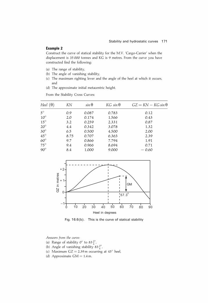
Example 2Construct the curve of statical stability for the M.V. `Cargo-Carrier' when thedisplacement is 35 000 tonnes and KG is 9 metres. From the curve you haveconstructed ®nd the following:
(a) The range of stability,(b) The angle of vanishing stability,(c) The maximum righting lever and the angle of the heel at which it occurs,
and(d) The approximate initial metacentric height.
From the Stability Cross Curves:
Answers from the curve:(a) Range of stability 0� to 83 3
4�,
(b) Angle of vanishing stability 83 34�,
(c) Maximum GZ� 2.39m occurring at 45� heel,(d) Approximate GM� 1.4m.
Stability and hydrostatic curves 171
Heel �y� KN sin y KG sin y GZ� KNÿ KG sin y
5� 0.9 0.087 0.783 0.1210� 2.0 0.174 1.566 0.4315� 3.2 0.259 2.331 0.8720� 4.4 0.342 3.078 1.3230� 6.5 0.500 4.500 2.0045� 8.75 0.707 6.363 2.3960� 9.7 0.866 7.794 1.9175� 9.4 0.966 8.694 0.7190� 8.4 1.000 9.000 ÿ 0.60
Fig. 16.6(b). This is the curve of statical stability

3. Hydrostatic curvesHydrostatic information is usually supplied to the ship's of®cer in the formof a table or a graph. Figure 16.7 shows the hydrostatic curves for theimaginary ship M.V. `Tanker'. The various items of hydrostatic informationare plotted against draft.When information is required for a speci®c draft, ®rst locate the draft on
the scale on the left-hand margin of the ®gure. Then draw a horizontal linethrough the draft to cut all of the curves on the ®gure. Next draw aperpendicular through the intersections of this line with each of the curvesin turn and read off the information from the appropriate scale.
Example 1Using the hydrostatic curves for M.V. `Tanker', take off all of the informationpossible for the ship when the mean draft is 7.6 metres.
(1) TPC� 39.3 tonnes(2) MCT 1 cm� 475 tonnes-metres(3) Displacement � 33 000 tonnes(4) Longitudinal centre of ¯otation is 2.2m forward of amidships(5) Longitudinal centre of buoyancy is 4.0 m forward of amidships.
When information is required for a speci®c displacement, locate the displace-ment on the scale along the top margin of the ®gure and drop a perpendicularto cut the curve marked `Displacement'. Through the intersection draw ahorizontal line to cut all of the other curves and the draft scale. The variousquantities can then be obtained as before.
Example 2From the hydrostatic curves take off the information for M.V. `Tanker' whenthe displacement is 37 500 tonnes.
(1) Draft� 8.55m(2) TPC� 40 tonnes(3) MCT 1 cm� 500 tonnesm(4) Longitudinal centre of ¯otation is 1.2m forward of amidships.(5) Longitudinal centre of buoyancy is 3.7 m forward of amidships.
The curves themselves are produced from calculations involving Simpson'sRules. These involve half-ordinates, areas, moments and moments of inertia foreach water line under consideration.
Using the hydrostatic curvesAfter the end drafts have been taken it is necessary to interpolate to ®ndthe `mean draft'. This is the draft immediately below the LCF which may beaft, forward or even at amidships. This draft can be labelled dH.If dH is taken as being simply the average of the two end drafts then in
large full-form vessels (supertankers) and ®ne-form vessels (container ships)an appreciable error in the displacement can occur. (See Fig. 16.8.)
172 Ship Stability for Masters and Mates
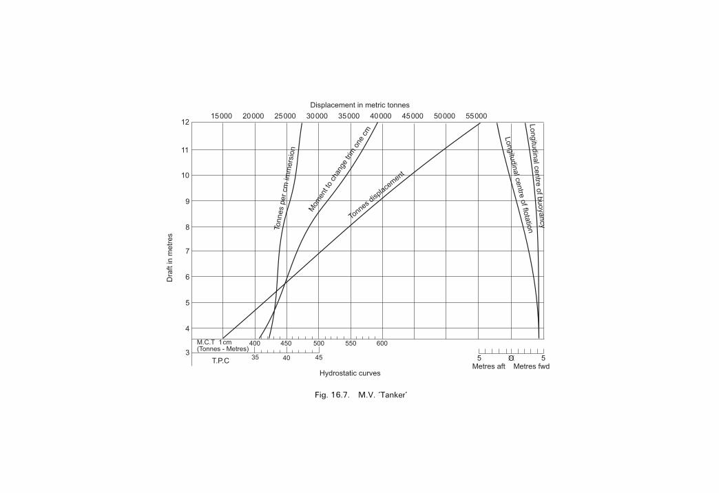
Fig. 16.7. M.V. `Tanker'

Let us assume the true mean draft `dH' is 6 m. The Navel Architect or mateon board ship draws a horizontal line parallel to the SLWL at 6m on thevertical axis right across all of the hydrostatic curves.At each intersection with a curve and this 6m line, he projects
downwards and reads off on the appropriate scale on the `x' axis.For our hydrostatic curves, at a mean draft of 6m, for example, we would
obtain the following:
TPC � 19:70 t
MCTC � 152:5 tm/cm
LCB � 0:80m forward
KMT � 7:46m
DisplaceMT � 10 293 t
LCF � 0:05m forward
KML � 207:4m
These values can then be used to calculate the new end drafts and transversestability, if weights are added to the ship, discharged from the ship or simplymoved longitudinally or transversely within the ship.LCF and LCB are distances measured from amidships (�e�).
Nowadays these values can be put on a spreadsheet in a computerpackage. When the hydrostatic draft dH is keyed, the hydrostatic valuesappertaining to this draft are then displayed, ready for use.A set of hydrostatic values has been calculated for a 135m General
Cargo Ship of about 10 000 tonnes deadweight. These are shown overpage.From those values a set of hydrostatic curves were drawn. These are shownin Fig. 16.9.
174 Ship Stability for Masters and Mates
�e�
�e�
Draft
Fig. 16.8
�e��e�
�e� �e�
�e�
�e�

�e�
�e��e�
Hydrostatic values for Fig. 16.9 (overpage). These are for a 135m LBP General Cargo Ship
Draft dH TPC KB DisplaceMT KML MCTC KMT LCF LCB(see below) tonnes m tonnes m tm/cm m m mm
9m 20.64 4.80 16 276 146.5 167.4 7.71 2.10 aft 0.45 aft8 m 20.36 4.27 14 253 161.8 162.9 7.54 1.20 aft7 m 20.06 3.74 12 258 181.5 158.1 7.44 0.50 aft 0.45 forward6m 19.70 3.21 10 293 207.4 152.5 7.46 0.05 forward 0.80 forward5m 19.27 2.68 8361 243.2 145.9 7.70 0.42 forward 1.05 forward4m 18.76 2.15 6486 296.0 138.3 8.28 0.70 forward 1.25 forward3m 18.12 1.61 4674 382.3 129.1 9.56 0.83 forward 1.30 forward212 m 17.69 1.35 3785 449.0 123.0 10.75 0.85 forward 1.30 forward
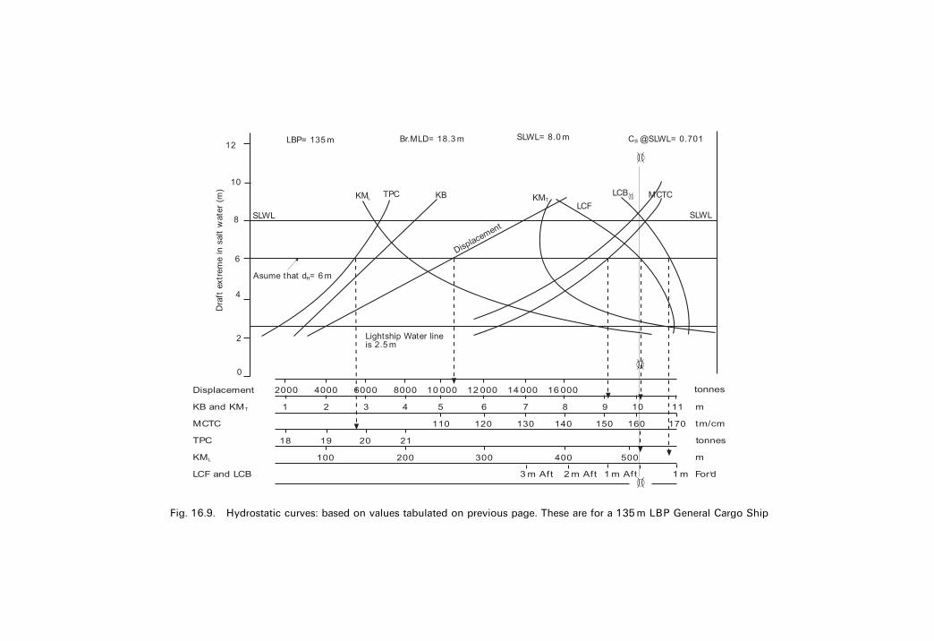
Fig. 16.9. Hydrostatic curves: based on values tabulated on previous page. These are for a 135m LBP General Cargo Ship
�e�
�e�
�e�
�e�
Stability and hydrostatic curves 177
EXERCISE 16
1 Plot the curve of stability for M.V. `Tanker' when the displacement is34 500 tonnes and KG� 9m. From this curve ®nd the approximate GM,the range of stability, the maximum GZ and the angle of heel at which itoccurs.
2 Plot the curve of statical stability for M.V. `Tanker' when the displacementis 23 400 tonnes and KG� 9.4 m. From this curve ®nd the approximateGM, the maximum moment of statical stability and the angle of heel atwhich it occurs. Find also the range of stability.
3 The displacement of M.V. `Tanker' is 24 700 tonnes and KG� 10m.Construct a curve of statical stability and state what information may bederived from it. Find also the moments of statical stability at 10 degreesand 40 degrees heel.
4 Using the cross curves of stability for M.V. `Tanker':(a) Draw a curve of statical stability when the displacement is 35 000
tonnes, KG� 9.2 metres, and KM� 11.2 m, and(b) From this curve determine the moment of statical stability at 10
degrees heel and state what other information may be obtained fromthe curve.
5 Plot the stability curve for M.V. `Tanker' when the displacement is 46 800tonnes and KG� 8.5 metres. From this curve ®nd the approximate GM,the range of stability, the maximum GZ and the angle of heel at which itoccurs.
6 From the hydrostatic curves for M.V. `Tanker' ®nd the mean draft whenentering a dock where the density of the water is 1009 kg per cu. m, if themean draft in salt water is 6.5 m.
7 Find the mean draft of M.V. `Tanker' in dock water of density 1009 kg percu. m when the displacement is 35 400 tonnes.
8 M.V. `Tanker' is 200m long and is ¯oating at the maximum permissibledraft aft. There is one more parcel of heavy cargo to load on deck to puther down to her marks at the load displacement of 51 300 tonnes. Find theposition, relative to amidships, to load the parcel so as to maintain themaximum possible trim by the stern.
9 Using the hydrostatic curves for M.V. `Tanker' ®nd the displacement,MCT 1 cm and the TPC, when the ship is ¯oating in salt water at a meandraft of 9 metres.
Also ®nd the new mean draft if she now enters a dock where thedensity of the water is 1010 kg per cu. m.
10 M.V. `Tanker' is 200m long and has a light displacement of 16 000 tonnes.She has on board 100 tonnes of cargo, 300 tonnes of bunkers, and 100tonnes of fresh water and stores. The ship is trimmed 1.5 m by the stern.Find the new drafts if the 100 tonnes of cargo already on board is nowshifted 50m forward.
11 Construct the curve of statical stability for M.V. `Cargo-Carrier' when
178 Ship Stability for Masters and Mates
the displacement is 35 000 tonnes and KG is 8 metres. From this curve®nd(a) the range of stability,(b) the angle of vanishing stability and,(c) the maximum GZ and the heel at which it occurs.
12 Construct the curve of statical stability for M.V. `Cargo-Carrier' when thedisplacement is 28 000 tonnes and the KG is 10 metres. From the curve®nd(a) the range of stability,(b) the angle of vanishing stability, and(c) the maximum GZ and the heel at which it occurs.
13 A vessel is loaded up ready for departure. KM is 11.9 m. KG is 9.52mwith a displacement of 20 550 tonnes. From the ship's Cross Curves ofStability, the GZ ordinates for a displacement of 20 550 tonnes and aVCG of 8m above base are as follows
Angle of heel �y� 0 15 30 45 60 75 90GZ ordinate (m) 0 1.10 2.22 2.60 2.21 1.25 0.36
Using this information, construct the ship's Statical Stability curve for thiscondition of loading and determine the following:(a) Maximum righting lever GZ.(b) Angle of heel at which this maximum GZ occurs.(c) Angle of heel at which the deck edge just becomes immersed.(d) Range of stability.
14 Using the table of KN ordinates below calculate the righting levers for aship when her displacement is 40 000 tonnes and her actual KG is 10m.Draw the resulting Statical Stability curve and from it determine:(a) Maximum GZ value.(b) Approximate GM value.(c) Righting moment at the angle of heel of 25�.(d) Range of Stability.
Angle of heel �y� 0 5 10 15 20 30 45 60KN ordinates (m) 0 0.90 1.92 3.11 4.25 6.30 8.44 9.39
Angle of heel �y� 75 90KN ordinates (m) 9.29 8.50

Chapter 17
Increase in draft due tolist
1. Box-shaped vesselsThe draft of a vessel is the depth of the lowest point below the waterline.When a box-shaped vessel is ¯oating upright on an even keel as in Figure17.1(a) the draft is the same to port as to starboard. Let the draft be `d' andlet the vessel's beam be `b'.
Now consider the same vessel when listed y degrees as shown in Figure17.1(b). The depth of the lowest point or draft is now increased to `D' (XY).
Fig. 17.1(a)
Fig. 17.1(b)

In triangle OXA:
OA � 12 b and angle AXO � 90� ; AX � 1
2 b sin y�
In triangle ABY:
AB � d and angle AYB � 90� ; AY � d cos y�
D � XY
� AX� AY
D � 12 b sin y� d cos y
or
New draft � 12 beam sin list�Old draft cos list
Note. It will usually be found convenient to calculate the draft when listedby using the triangles AOX and ABY.
Example 1A box-shaped ship with 12m beam is ¯oating upright at a draft of 6.7 m. Findthe increase in draft if the vessel is now listed 18 degrees.
In triangle OAX:Angle AOX � 18�
Therefore use course 18�OA (Dist.) � 6:0m
AX (Dep.) � 1:85mIn triangle ABY:
Angle BAY � 18�
Therefore use course 18�
AB (Dist.) � 6:7m
AY (D. Lat.) � 6:37m
180 Ship Stability for Masters and Mates
Fig. 17.2(a)

AX � 1:85m
AY � �6:37mNew draft � 8:22m
Old draft � �6:70m1:52m
Ans. Increase � 1:52m
Example 2Using the dimensions of the ship given in example 1, proceed to calculate theincrease in draft at 3� intervals from 0� to 18�. Plot a graph of draft increase/ y.
12 beam sin y � 1
2� 12� sin y � 6 sin y �I�Old draft cos y � 6:7 cos y �II�
Increase in draft� (I)� (II)ÿOld draft in metres.
The above results clearly show the increase in draft or loss of underkeelclearance when a vessel lists.Ships in the late 1990s are being designed with shorter lengths and wider
breadths mainly to reduce ®rst cost and hogging/sagging characteristics.These wider ships are creating problems sometimes when initial underkeel
clearance is only 10 per cent of the ship's static draft. It only requires a smallangle of list for them to go aground in way of the bilge strakes.One ship, for example, is the supertanker Esso Japan. She has an LBP of 350m
and a width of 70m at amidships. Consequently extra care is required shouldpossibilities of list occur.Figure 17.2(b) (on page 182) shows the requested graph of draft increase /y.
2. Vessels having a rise of ¯oor
Example 3A ship has 20m beam at the waterline and is ¯oating upright at 6 m draft. If therise of ¯oor is 0.25m, calculate the new draft if the ship is now listed 15 degrees(See Figure 17.3)
Increase in draft due to list 181
Angle of list 6 sin y 6.7 cos y Old draft Increase in draft (m)
0� 0 6.70 6.70 03� 0.31 6.69 6.70 0.306� 0.63 6.66 6.70 0.599� 0.94 6.62 6.70 0.8612� 1.25 6.55 6.70 1.1015� 1.55 6.47 6.70 1.3218� 1.85 6.37 6.70 1.52

182 Ship Stability for Masters and Mates
Fig. 17.2(b). Draft increase / angle of list y
Fig. 17.3
In triangle OAX:Angle O � 15�
Therefore use course 15�AO (Dist.) � 10m
AX (Dep.) � 2:59mIn triangle ABY:
Angle A � 15�
Therefore use course 15�
AB (Dist.) � ACÿ BC
� Old draftÿ Rise of floor
� 6mÿ 0:25m
AB (Dist.) � 5:75m
AY (D. Lat.) � 5:55m
AX � 2:59m
AY � �5:55mXY � 8:14m
Ans. New draft � 8:14 metresIf the formula is to be used to ®nd the new draft it must now be amended to
allow for the rise of ¯oor as follows:
New draft � 12 beam sin list� (Old draftÿ Rise� cos list.
Note. In practise, the shipbuilder's naval architect usually calculates the increasein draft for the ship at various angles of list and suppliers the information to theship's of®cer by means of a table on the plans of the ship.The rise of ¯oor, similar to tumblehome on merchant ships, has almost
become obsolute on merchant ships of today.
Increase in draft due to list 183
Exercise 17
1 A box-shaped vessel with 10m beam, and 7.5 m deep, ¯oats upright at adraft of 3m. Find the increase of draft when listed 15 degrees to starboard.
2 A ship 90m long, 15m beam at the waterline, is ¯oating upright at a draftof 6m. Find the increase of draft when the ship is listed 10 degrees,allowing 0.15m rise of ¯oor.
3 A box-shaped vessel 60m� 6m� 4m draft is ¯oating upright. Find theincrease in the draft if the vessel is now listed 15 degrees to port.
4 A box-shaped vessel increases her draft by 0.61m when listed 12 degreesto starboard. Find the vessel's beam if the draft, when upright, was 5.5 m.
5 A box-shaped vessel with 10m beam is listed 10 degrees to starboard andthe maximum draft is 5 m. A weight already on board is shiftedtransversely across the deck, causing the vessel to list to port. If the ®nallist is 5 degrees to port, ®nd the new draft.
Chapter 18
Water pressureThe water pressure at any depth is due to the weight of water above thepoint in question and increases uniformly with depth below the surface.From this it can be seen that the pressure at any depth will vary with thedepth below the surface and the density of the water.
Pressure at any depthConsider an area of 1 sqm at the water level as shown by ABCD in Figure18.1. The water pressure on this area is zero as there is no water above it.Now consider the area EFGH which is submerged to a depth of 1m
below the surface. There is 1 cu. m of water above it. Let the density of thewater be `w' tonnes per cu. m. Then the pressure on this area is `w' tonnesper sqm, and the total pressure or thrust on an area of `A' sq m whosecentre of gravity is 1 m below the surface, will be wA tonnes.Next consider the area IJKL whose centre of gravity is 2m below the
surface. The pressure is now due to 2 cu. m of water and will be 2w tonnesper sqm. Also, the total pressure or thrust on any area whose centre ofgravity is 2 m below the surface, is 2 wA tonnes.Similarly, the pressure on the area MNOP will be 3w tonnes per sq
metre, and the total pressure or thrust on any area whose centre of gravityis 3 m below the surface will be 3wA tonnes.The following formulae may now be deduced:
Total pressure or thrust � w�A� h tonnes
where
h � the depth of the centre of gravity below the surface
w � the density of the water in tonnes/m3, and
A � the area in sqm.

Example 1Find the water pressure and the total thrust on the ¯at plate keel of a ship whichis ¯oating on an even keel at 4 metres mean draft in water of density 1.024 t/m3 per cu. m. The keel plate is 35m long and 1.5m wide.
Pressure � 4� 1:024 � 4:1 tonnes/m2
Total Thrust � w� A� h
� 1:024� 35� 1:5� 4
Total Thrust � 215:04 tonnes
Example 2A lock gate which is 15m wide has salt water on one side to a depth of 8m andfresh water on the other side to a depth of 9m. Find the resultant thrust on thelock gate and state on which side of the gate it acts.
Water pressure 185
Fig. 18.1
Fig. 18.2

Let P1 � thrust on the SW side, and P2 � thrust on the FW side
; P1 � Pressure on the SW side
P1 � rSW � A� h1
� 1:025� 15� 8� 82
P1 � 492 tonnes
; P2 � Pressure on the FW side
P2 � rFW � A� h2
� 1:000� 15� 9� 92
P2 � 607:5 tonnes
Resultant thrust � P2 ÿ P1
� 607:5ÿ 492
Ans. Resultant thrust � 115.5 tonnes on the FW side
Example 3Find the pressure and total thrust on two deep tank lids, each 4m� 2.5 m,resting on coamings 30 cm high, when the tank is ®lled with salt water to ahead of 9.3m above the crown of the tank.
Pressure at A � Pressure at B (see Figure 18.3)
� w� A� h
� 1:025� 1:0m2 � 9:0
Pressure on lids � 9:225 tonnes per sqm
Total thrust � 2� thrust on one lid
� 2� (P� A)
� 2� 9:225� 4� 2:5 tonnes
Total thrust � 184:5 tonnes
Ans. Pressure � 9:225 tonnes per sqm. Total thrust � 184:5 tonnes.
186 Ship Stability for Masters and Mates
Fig. 18.3

Water pressure 187
Exercise 18
1 A sealed box is made of metal and is capable of withstanding a pressure of15.54 kN per sq m. Find to what depth the box may be submerged in saltwater before it collapses.
2 Find the water pressure, in kilo-newtons per sq m, on the keel of a shipwhich is ¯oating upright on an even keel in salt water at a draft of 6metres.
3 A ship is ¯oating on an even keel in salt water at a draft of 7 metres. Shehas a ¯at plate keel which is 100m long and 2m wide. Find the waterpressure and the total thrust on the keel due to the water.
4 Find the water pressure and thrust on a ¯at plate keel 6 m long and 1.5mwide when the ship is ¯oating on an even keel at 6 m draft in salt water.
5 Find the water pressure and thrust on the inner bottom plating of a doublebottom tank (10m� 10m) when the tank is ®lled with fresh water to ahead of 9m above the crown of the tank.
6 A deep tank has two lids, each 4m� 3m, resting on coamings which are30 cm high. Find the water pressure on each of the two lids and the totalthrust on both lids when the tank is ®lled with salt water to a head of6.3m above the crown of the tank.
7 A rectangular plate 2m� 1m is held vertically in fresh water with the 2medge on the waterline. Find the thrust on one side of the plate.
8 A lock gate 12m wide has water of density 1010 kg per cu. m to a depthof 10m on one side and water of density 1015 kg per cu. m to a depth of6m on the other side. Find the resultant thrust on the lock gate and stateon which side it acts.
9 A lock gate is 20m wide and has water of density 1016 kg per cu. m onone side to a depth of 10m and salt water on the other side to a depth of7.5m. Find the resultant thrust and state on which side of the gate it willact.
10 Find the total water pressure acting on a box-shaped barge keel platingwhich is 60m long 10m wide, and is ¯oating upright in salt water on aneven keel at 5 m draft.
11 A box-shaped barge has a rectangular collision bulkhead 10m wide and6m deep. Find the total water pressure on this bulkhead if the forepeak is¯ooded to a depth of 5m with salt water.

Chapter 19
Combined list and trimWhen a problem involves a change of both list and trim, the two parts mustbe treated quite separately. It is usually more convenient to tackle the trimpart of the problem ®rst and then the list, but no hard and fast rule can bemade on this point.
Example 1A ship of 6000 tonnes displacement has KM� 7m, KG� 6.4 m, and MCT1 cm� 120 tonnes m. The ship is listed 5 degrees to starboard and trimmed0.15m by the head. The ship is to be brought upright and trimmed 0.3 m bythe stern by transferring oil from No. 2 double bottom tank to No. 5 doublebottom tank. Both tanks are divided at the centre line and their centres ofgravity are 6m out from the centre line. No. 2 holds 200 tonnes of oil on eachside and is full. No. 5 holds 120 tonnes on each side and is empty. The centre ofgravity of No. 2 is 23.5 m forward of amidships and No. 5 is 21.5 m aft ofamidships. Find what transfer of oil must take place and give the ®naldistribution of the oil. (Neglect the effect of free surface on the GM.)Assume that LCF is at amidships.
(a) To bring the ship to the required trim
Present trim � 0:15m by the headJ
Required trim � 0:30m by the sternI
Change of trim � 0:45m by the sternI
� 45 cm by the sternI
Trim moment � Change of trim�MCT 1 cm
� 45� 120
Trim moment � 5400 tonnesm by the sternI
Let `w' tonnes of oil be transferred aft to produce the required trim.
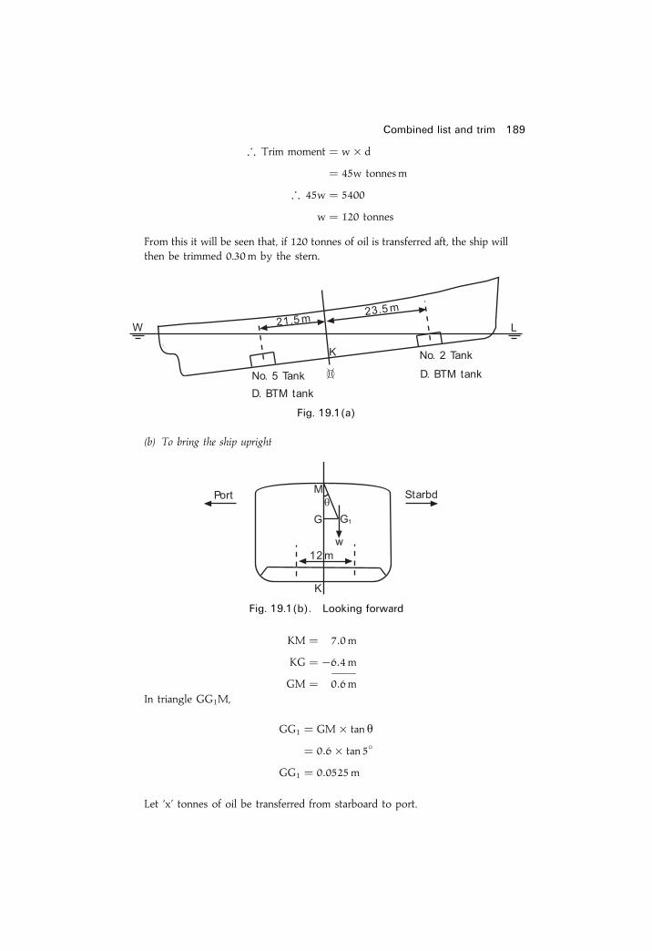
; Trim moment � w� d
� 45w tonnes m
; 45w � 5400
w � 120 tonnes
From this it will be seen that, if 120 tonnes of oil is transferred aft, the ship willthen be trimmed 0.30m by the stern.
(b) To bring the ship upright
KM � 7:0m
KG � ÿ6:4mGM � 0:6m
In triangle GG1M,
GG1 � GM� tan y
� 0:6� tan 5�
GG1 � 0:0525m
Let `x' tonnes of oil be transferred from starboard to port.
Combined list and trim 189
�e�
Fig. 19.1(a)
Fig. 19.1(b). Looking forward

Moment to port � x� d
� 12x tonnes m
Initial moment to starboard � W� GG1
� 6000� 0:0525
� 315 tonnes m
But if the ship is to complete the operation upright:
Moment to starboard � Moment to portor
315 � 12x
x � 26:25 tonnes
The ship will therefore be brought upright by transferring 26.25 tonnes fromstarboard to port.From this it can be seen that, to bring the ship to the required trim and
upright, 120 tonnes of oil must be transferred from forward to aft and 26.25tonnes from starboard to port. This result can be obtained by taking 120 tonnesfrom No. 2 starboard and by putting 93.75 tonnes of this oil in No. 5 starboardand the remaining 26.25 tonnes in No. 5 Port tank.The distributions would then be as follows:
Note. There are, of course, alternative methods by which this result could havebeen obtained, but in each case a total of 120 tonnes of oil must be transferredaft and 26.25 tonnes must be transferred from starboard to port.
190 Ship stability

Combined list and trim 191
Exercise 19
1 A tanker has displacement of 10 000 tonnes, KM� 7m, KG� 6.4m andMCT 1 cm� 150 tonnes m. There is a centre line bulkhead in both No. 3and No. 8 tanks. Centre of gravity of No. 3 tank is 20m forward of thecentre of ¯otation and the centre of gravity of No. 8 tank is 30m aft of thecentre of ¯otation. The centre of gravity of all tanks is 5m out from thecentre line. At present the ship is listed 4 degrees to starboard and trimmed0.15m by the head. Find what transfer of oil must take place if the ship is tocomplete upright and trimmed 0.3m by the stern.
2 A ship of 10 000 tonnes displacement is listed 5 degrees to port andtrimmed 0.2 m by the head. KM� 7.5m, KG 6.8m, and MCT 1 cm� 150tonnesm. Centre of ¯otation is amidships. No.1 double bottom tank isdivided at the centre line, each side holds 200 tonnes of oil and the tank isfull. No. 4 double bottom tank is similarly divided each side having acapacity of 150 tonnes, but the tank is empty. The centre of gravity of No.1 tank is 45m forward of amidships and the centre of gravity of No. 4 tankis 15m aft of amidships. The centre of gravity of all tanks is 5 m out fromthe centre line. It is desired to bring the ship upright and trimmed 0.3 m bythe stern by transferring oil. If the free surface effect on GM be neglected,®nd what transfer of oil must take place and also the ®nal distribution of theoil.
3 A ship of 6000 tonnes displacement, KG� 6.8m., is ¯oating upright in saltwater, and the draft is 4m F and 4.3 m A. KM� 7.7 m TPC� 10 tonnes.MCT 1 cm� 150 tonnesm. There is a locomotive to discharge from No. 2lower hold (KG� 3m, and centre of gravity 30m forward of the centre of¯otation which is amidships). If the weight of the locomotive is 60 tonnesand the height of the derrick head is 18m above the keel and 20m out fromthe centre line when plumbing overside, ®nd the maximum list during theoperation and the drafts after the locomotive has been discharged. AssumeKM is constant.
4 A ship displaces 12 500 tonnes, is trimmed 0.6 m by the stern and listed 6degrees to starboard. MCT 1 cm 120 tonnesm, KG 7.2 m, KM 7.3m No. 2and No. 5 double bottom tanks are divided at the centre line. Centre ofgravity of No. 2 is 15m forward of the centre of ¯otation and centre ofgravity of No. 5 is 12m abaft centre of ¯otation. Centre of gravity of alltanks is 4 m out from the centre line. The ship is to be brought upright andon to an even keel by transferring oil from aft to forward, taking equalquantities from each side of No. 5. Find the amounts of oil to transfer.

Chapter 20
Calculating the effectof free surface ofliquids (FSE)The effect of free surface of liquids on stability was discussed in generalterms in Chapter 7, but the problem will now be studied more closely andthe calculations involved will be explained.When a tank is partially ®lled with a liquid, the ship suffers a virtual loss
in metacentric height which can be calculated by using the formula:
FSE � Virtual loss of GM � i
W� r� 1
n2metres �I�
wherei � the second moment of the free
surface about the centre line, in m4
w � the ship's displacement, in tonnesr � the density of the liquid in the tank, in tonnes/cu. mn � the number of the longitudinal compartments
into which the tank is subdividedi� p � free surface moment, in tonnesm.
The derivation of this formula is as follows:The ship shown in Figure 20.1(a) has an undivided tank which is partially
®lled with a liquid.When the ship is inclined, awedge of the liquid in the tankwill shift from the
high side to the low side such that its centre of gravity shifts from g to g1. Thiswill cause the centre of gravity of the ship to shift from G to G1, where
GG1 � w� gg1W
Letr1 � density of the liquid in the tank
andr2 � density of the water in which the ship floats
then
GG1 � v� r1 � gg1V� r2

Had there been no free surface when the ship inclined, the righting leverwould have been GZ. But, due to the liquid shifting, the righting lever isreduced to G1Z1 or GvZv. The virtual reduction of GM is therefore GGv.For a small angle of heel:
GG1 � GGv � y
; GGv � y � v� gg1 � r1V� r2
or
GGv � v� gg1 � r1V� y� r2
From the proof of BM� I/V, I� y � v� gg1Let i� the second moment of the free surface about the centre line.Then
GGv � i� r1V� r2
This is the formula to ®nd the virtual loss of GM due to the free surfaceeffect in an undivided tank.Now assume that the tank is subdivided longitudinally into `n' compart-
ments of equal width as shown in Figure 20.1(b).Let
l � length of the tank, and
b � breadth of the tank.
The breadth of the free surface in each compartment is thus b/n, and the
second moment of each free surface is given byl� (b/n)3
12
Calculating the effect of free surface of liquids (FSE) 193
Fig. 20.1(a)

GGv � virtual loss of GM for one compartmentmultiplied by the number of compartments.
� i� r1V� r2
� n
where
i � the second moment of the water-plane areain one compartment about the centre line.
� l� (b/n)3 � r112� V� r2
� n
� l� b3 � r112� V� n3 � r2
� n
or
GGv � i
V� r1r2� 1
n2
where
i � the second moment of the water-plane area ofthe whole tank about the centre line.
ButW � V� r2
so
GGv � i
W� r1 �
1
n2
as shown in equation (I).
194 Ship Stability for Masters and Mates
Fig. 20.1(b)

This is the formula to ®nd the virtual loss of GM due to the free surfaceeffect in a tank which is subdivided longitudinally.From this formula it can be seen that, when a tank is subdivided
longitudinally, the virtual loss of GM for the undivided tank is dividedby the square of the number of compartments into which the tank isdivided. Also note that the actual weight of the liquid in the tank will haveno effect whatsoever on the virtual loss of GM due to the free surface.For a rectangular area of free surface, the second moment to be used in
the above formula can be found as follows:
i � LB3
12
whereL � the length of the free surface, and
B � the total breadth of the free surface, ignoring divisions.
Note. Transverse subdivisions in partially ®lled tanks (slack tanks) do nothave any in¯uence on reducing free surface effects.However, ®tting longitudinal bulkheads do have a very effective in¯uence
in reducing this virtual loss in GM.
Example 1A ship of 8153.75 tonnes displacement has KM� 8m, KG� 7.5 m, and has adouble bottom tank 15m� 10m� 2m which is full of salt water ballast. Findthe new GM if this tank is now pumped out till half empty.
Note. The mass of the water pumped out will cause an actual rise in theposition of the ship's centre of gravity and the free surface created will cause avirtual loss in GM. There are therefore two shifts in the position of the centreof gravity to consider.In Figure 20.2 the shaded portion represents the water to be pumped out
with its centre of gravity at position g. The original position of the ship's centreof gravity is at G.
Calculating the effect of free surface of liquids (FSE) 195
Fig. 20.2

��� ��� �������� �� ��� �� ���� �� � � � �� �� ���� ����������
�� ���� �� ����� ��������� ��� � ��� ��� �� ����� ����
� � ������ ����
�� � �� � � � ������� ������
� ��� ����
��� � �� �
��
� ������� !
���
��� � ������
��� ���" �������� �� "��� �� ���� �� �# � � �� ���� � ����� �� ���� � �����$
���" � �
�� �� �
�
�
�� ��� �% ���� �&�
� �
� ���" � �
��� �'�
��
���" � � (�
��� �'�
��� �
�
���� � �# � )'*
��
���" � ��� ��� � �����
��� ������� � ���!�� �
+�� ,# � �����
+�� ,� � ������
+�� �# � ������
-�� �� ���� �� � � ������
��� �� � �#�����
���" � .��� �� ���� �� � � ���!�� �� ������
���� /�� �# � ������ � �#�����
��� ���� ������� �� ������ �� ����

Hence G1 has risen due to the discharge of the ballast water (loading change)and has also risen due to Free Surface Effects.Be aware that in some cases these two rises of G do not take G above M
thereby making the ship unstable.
Example 2A ship of 6000 tonnes displacement, ¯oating in salt water, has a double bottomtank 20m� 12m� 2m which is divided at the centre line and is partially ®lledwith oil of relative density 0.82. Find the virtual loss of GM due to the freesurface of the oil.
Virtual loss of GM � i
W� roil �
1
n2
� lb3
12� roil �
1
W� 1
n2
� 20� 123
12� 6000� 0:820� 1
22
Ans. Virtual loss of GM � 0:098 metres
Example 3A ship of 8000 tonnes displacement has KM 7.5m, and KG 7.0m. A doublebottom tank is 12m long, 15m wide and 1m deep. The tank is dividedlongitudinally at the centre line and both sides are full of salt water. Calculatethe list if one side is pumped out until it is half empty. (See Fig. 20.3.)
Mass of water discharge � lDB � bDB � dDB2� rSW
Mass of water discharged � 12� 7:5� 0:5� 1:025
w � 46:125 tonnes
Vertical shift of G(GG1) � w� d
W2
� 46:125� 6:25
8000ÿ 46:125� 46:125� 6:25
7953:875
� 0:036 metres
Horizontal shift of G(GvG2) � w� d
Wÿ w
� 46:125� 3:75
7953:875
� 0:022 metres
Virtual loss of GM(G1Gv) � l� b3212� rSW
W2� 1
n2
� 12� 7:53
12� 1:025
7953:875� 1
12
� 0:054 metres
Calculating the effect of free surface of liquids (FSE) 197

KM � 7:500 metres
Original KG � 7:000 metres
Original GM � 0:500 metres � GMsolid
Vertical rise of G(GG1) � 0:036 metres "
G1M � 0:464 metres � G1Msolid
Virtual loss of GM(G1Gv) � 0:054 metres
New GM(GvM) � 0:410 metres � GMfluid
In triangle GvG2M:
tan y � G2Gv
GvM
� 0:022
0:410� 0:0536
Ans. List � 3� 040
198 Ship Stability for Masters and Mates
Fig. 20.3
So again G has risen due to discharging water ballast.It has also risen due to free-surface effects. A furthermovement has caused G to move off the centrelineand has produced this angle of list of 3� 040.

��� ������� ����� ������� ����� ��� ������ �� ��� ������� � ��������� � ������� �� ���� ������� ������� ��������������� � ���� ��� � ���������� �� � ����! " ��� ������ �� �
��������� �����#������ ��� $%� �� � &� �� �! ���� ��� ����������' (��� ���� ������� ����� ���� � ����' �� $! )% �*��!+� ��� ,-� ������� ���� ������� ������� �� !$&� ��������� ��� ������� ����
� ,-� � ��� (�� ,-� ��� ��� ����� ������ ��� ����
��� � �������� ������� � (��� .��� �� ��������� ������� (��� �� �� #����.��� �� ����� ��� ������� (��� � �/ �� ��� ���.� � ��� ����� ��� ������� � (��� ��� ����� �0��� �������!
����
����������� ���� � ,-� �� ���� � ,� +� ��1
1
� �� ��$ � ��1
$)�1���� ��� ) �2����
� ������� ���� � ,-� � $%� &� � $� )%
� � $)
� � )$&3� �
� ,-� �����' � �$& � �)$&3
� � � �&3� �
�!�! ������� ����44
���������� �� ������ � ���� ������� � ������� ����� ���
��� �������

��������� ��� � ��� �� ���� � �� �� �� � ������� � ��� ���� ���� ��������
� ����� ��� � �� ���� �� � �����
��� ����� ������ �
�!�� �� � � �"�� � #�� $�� ��� %� ��&�� �' �� ( �� (� (�)�) �!�*��� � �� ������ )������ ��+!�)� � � +� )��� �� ��)�(� �!� #������#(� �##�(��� �!�$ �� ��� � ����,,
���������( ��� � ��� �� ���� � ���� ����
���� ���
� ����� ��� � ��� ��������������
��� ���� ���� ���� �����(��
������� � ���� �� �# �"�� �� $�� ��-� (�
#� ��� � ������� ������ � ������� �!�$ �� �����
��� ���� ������� � � ������� ��� �����
���� ������
���� �������

GMT is now �ve, but below the minimum GMT of 0.15m that isallowable by D.Tp. regulations.
FSE�virtual loss in GMT or rise in G�3@ l1 � b3312�W
� rSW (see Fig. 20.4(d))
; Virtual loss in GMT �3� 15� 8
3
� �3�1:025
12�W
�0:0243m " i.e. 19 of answer to part (a)
Hence
final GMT � 0:1800ÿ 0:0243 � �0:1557m ship is stable.
Ship is stable and above D.Tp. minimum GMT value of 0.15m.So longitudinal divisional bulkheads (watertight or wash-bulkheads) are
effective. They cut down rapidly the loss in GMT. Note the 1/n2 law where
n is the number of equal divisions made by the longitudinal bulkheads.Free surface effects therefore depend on:
(I) density of slack liquid in the tank;(II) ship's displacement in tonnes;(III) dimensions and shape of the slack tanks;(IV) bulkhead subdivision within the slack tanks.
The longitudinal divisional bulkheads referred to in examples in this chapterneed not be absolutely watertight; they could have openings in them.Examples on board ship are the centreline wash bulkhead in the Fore Peaktank and in Aft Peak tank.
Calculating the effect of free surface of liquids (FSE) 201
Fig. 20.4(d)

202 Ship Stability for Masters and Mates
Exercise 20
1 A ship of 10 000 tonnes displacement is ¯oating in dock water of density1024 kg per cu. m, and is carrying oil of relative density 0.84 in a double-bottom tank. The tank is 25m long, 15m wide, and is divided at the centreline. Find the virtual loss of GM due to this tank being slack.
2 A ship of 6000 tonnes displacement is ¯oating in fresh water and has adeep tank (10m� 15m� 6m) which is undivided and is partly ®lled withnut oil of relative density 0.92. Find the virtual loss of GM due to the freesurface.
3 A ship of 8000 tonnes displacement has KG� 3.75m, and KM� 5.5 m. Adouble-bottom tank 16m� 16m� 1m is subdivided at the centre line andis full of salt water ballast. Find the new GM if this tank is pumped out untilit is half empty.
4 A ship of 10 000 tonnes displacement, KM 6m, KG 5.5m, is ¯oatingupright in dock water of density 1024 kg per cu. m. She has a doublebottom tank 20m� 15m which is subdivided at the centre line and ispartially ®lled with oil of relative density 0.96. Find the list if a mass of 30tonnes is now shifted 15m transversely across the deck.
5 A ship is at the light displacement of 3000 tonnes and has KG 5.5m, andKM 7.0m. The following weights are then loaded:
5000 tonnes of cargo KG 5m2000 tonnes of cargo KG 10m700 tonnes of fuel oil of relative density 0.96.
The fuel oil is taken into Nos. 2, 3 and 5 double bottom tanks, ®llingNos. 3 and 5, and leaving No. 2 slack.The ship then sails on a 20-day passage consuming 30 tonnes of fuel
oil per day. On arrival at her destination Nos. 2 and 3 tanks are empty,and the remaining fuel oil is in No. 5 tank. Find the ship's GM's for thedeparture and arrival conditions.
Dimensions of the tanks:
No. 2 15�15m� 1mNo. 3 22m� 15m� 1mNo. 5 12m� 15m� 1m
Assume that the KM is constant and that the KG of the fuel oil in everycase is half of the depth of the tank.
6 A ship's displacement is 5100 tonnes, KG� 4m, and KM� 4.8 m. Adouble-bottom tank on the starboard side is 20m long, 6 m wide and 1mdeep and is full of fresh water. Calculate the list after 60 tonnes of thiswater has been consumed.
7 A ship of 6000 tonnes displacement has KG 4m and KM 4.5m. A double-bottom tank in the ship 20m long and 10m wide is partly full of salt-water

Calculating the effect of free surface of liquids (FSE) 203
ballast. Find the moment of statical stability when the ship is heeled 5degrees.
8 A box-shaped vessel has the following data.
Length is 80m, breadth is 12m, draft even keel is 6 m, KG is 4.62m.
A double bottom tank 10m long, of full width and 2.4m depth is thenhalf-®lled with water ballast having a density of 1.025 t/m3. The tank islocated at amidships.Calculate the new even keel draft and the new transverse GM after
this water ballast has been put in the double bottom tank.

Chapter 21
Bilging andpermeabilityBilging amidships compartmentsWhen a vessel ¯oats in still water it displaces its own weight of water.Figure 21.1(a) shows a box-shaped vessel ¯oating at the waterline WL. Theweight of the vessel (W) is considered to act downwards through G, thecentre of gravity. The force of buoyancy is also equal to W and actsupwards through B, the centre of buoyancy. b�W.Now let an empty compartment amidships be holed below the waterline
to such an extent that the water may ¯ow freely into and out of thecompartment. A vessel holed in this way is said to be `bilged'.Figure 21.1(b) shows the vessel in the bilged condition. The buoyancy
provided by the bilged compartment is lost. The draft has increased and thevessel now ¯oats at the waterline W1L1, where it is again displacing its own
Fig. 21.1(a)

weight of water. `X' represents the increase in draft due to bilging. Thevolume of lost buoyancy (v) is made good by the volumes `y' and `z'.
; v � y� z
Let `A' be the area of the water-plane before bilging, and let `a' be thearea of the bilged compartment. Then:
y� z � Axÿ axor
v � x�Aÿ a�Increase in draft � x � v
Aÿ ai.e.
Increase in draft � Volume of lost buoyancy
Area of intact waterplane
Note. Since the distribution of weight within the vessel has not been alteredthe KG after bilging will be the same as the KG before bilging.
Example 1A box-shaped vessel is 50 metres long and is ¯oating on an even keel at 4metres draft. A compartment amidships is 10 metres long and is empty. Findthe increase in draft if this compartment is bilged. See Fig. 21.1(c).
x � v
Aÿ a� l� B� B
�Lÿ l�Blet
B � Breadth of the vesselthen
x � 10� B� 4
50� Bÿ 10� B
� 40B
40BIncrease in draft � 1 metre
Bilging and permeability 205
Fig. 21.1(b)

Example 2A box-shaped vessel is 150 metres long� 24 metres wide� 12 metres deepand is ¯oating on an even keel at 5 metres draft. GM� 0.9 metres. Acompartment amidships is 20 metres long and is empty. Find the new GM ifthis compartment is bilged.
Old KB � 12 Old draft
� 2:5m
Old BM � B2=12d
� 24� 24
12� 5
� 9:6m
Old KB � �2:5mOld KM � 12:1m
Old GM � ÿ0:9mKG � 11:2m
This KG will not change after bilging has taken place.
x � v
Aÿ a
� 20� 24� 5
150� 24ÿ 20� 24
� 2400
130� 24
Increase in draft � 0:77m
Old draft � 5:00m
New draft � 5:77m � say draft d2
206 Ship Stability for Masters and Mates
Fig. 21.1(c)

New KB � 1
2New draft � d2
2
� 2:89m
New BM � B2=12d2
� 24� 24
12� 5:77
� 8:32m�New KB � 2:89m
New KM � 11:21mÿAs before, KG � 11:20m
Ans. New GM � 0:01mThis is �ve but dangerously low in value!!
Permeability kPermeability is the amount of water that can enter a compartment or tankafter it has been bilged. When an empty compartment is bilged, the wholeof the bouyancy provided by that compartment is lost. Typical values forpermeability m are as follows:
Empty compartment m � 100%Engine room m � 80% to 85%Grain ®lled cargo hold m � 60% to 65%Coal ®lled compartment m � 36% approxFilled water ballast tank (when ship is in salt water) m � 0%
Consequently, the higher the value of the permeability for a bilgedcompartment, the greater will be a ship's loss of bouyancy when the ship isbilged.The permeability of a compartment can be found from the formula:
m � Permeability � Broken Stowage
Stowage Factor� 100 per cent
The broken stowage to be used in this formula is the broken stowage pertonne of stow.When a bilged compartment contains cargo, the formula for ®nding the
increase in draft must be amended to allow for the permeability. If `m'represents the permeability, expressed as a fraction, then the volume of lostbuoyancy will be `mn' and the area of the intact waterplane will be `Aÿ mn'square metres. The formula then reads:
x � mnAÿ ma
Example 3A box-shaped vessel is 64 metres long and is ¯oating on an even keel at 3
Bilging and permeability 207
metres draft. A compartment amidships is 12m long and contains cargo havinga permeability of 25 per cent. Calculate the increase in the draft if thiscompartment be bilged.
x � mnAÿ ma
�14� 12� B� 3
64� Bÿ 14� 12� B
� 9B
61B
Ans. Increase in draft � 0:15m
Example 4A box-shaped vessel 150m� 20m� 12m is ¯oating on an even keel at 5metres draft. A compartment amidships is 15 metres long and contains timberof relative density 0.8, and stowage factor 1.5 cubic metres per tonne. Calculatethe new draft if this compartment is now bilged.The permeability `m' must ®rst be found by using the formula given above.
i.e.
Permeability � BS
SF� 100 per cent � `m'
The stowage factor is given in the question. The broken stowage per tonneof stow is now found by subtracting the space which would be occupied byone tonne of solid timber from that actually occupied by one tonne of timber inthe hold. One tonne of fresh water occupies one cubic metre and the relativedensity of the timber is 0.8.
; Space occupied by one tonne of solid timber � 1
0:8
� 1:25 cubic metres
Stowage Factor � 1:50 cubic metres
; Broken Stowage � 0:25 cubic metres
Permeability `m' � BS
SF� 100 per cent
� 0:25
1:50� 100 per cent
� 100=6 per cent
; `m' � 1=6 or 16.67 per cent
Increase in draft � x � mnAÿ ma
� 1=6� 15� 20� 5
150� 20ÿ 1=6� 15� 20
� 250=2950 � 0:085m
208 Ship Stability for Masters and Mates
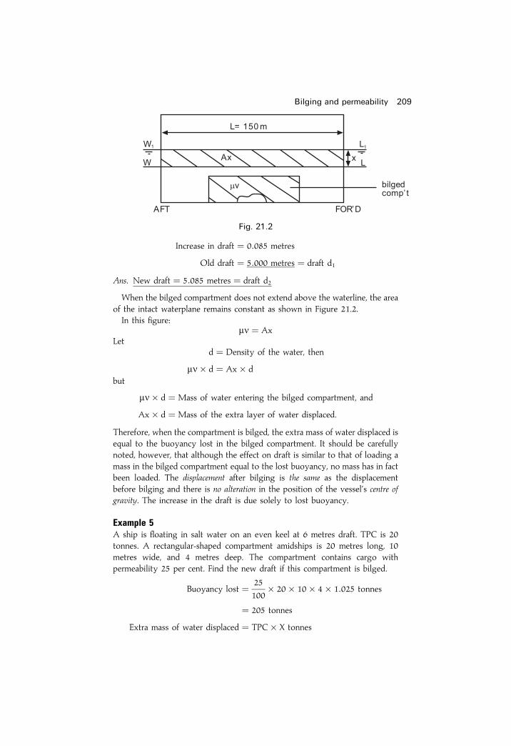
Increase in draft � 0:085 metres
Old draft � 5:000 metres � draft d1
Ans. New draft � 5:085 metres � draft d2
When the bilged compartment does not extend above the waterline, the areaof the intact waterplane remains constant as shown in Figure 21.2.In this ®gure:
mn � AxLet
d � Density of the water, then
mn� d � Ax� dbut
mn� d � Mass of water entering the bilged compartment, and
Ax� d � Mass of the extra layer of water displaced.
Therefore, when the compartment is bilged, the extra mass of water displaced isequal to the buoyancy lost in the bilged compartment. It should be carefullynoted, however, that although the effect on draft is similar to that of loading amass in the bilged compartment equal to the lost buoyancy, no mass has in factbeen loaded. The displacement after bilging is the same as the displacementbefore bilging and there is no alteration in the position of the vessel's centre ofgravity. The increase in the draft is due solely to lost buoyancy.
Example 5A ship is ¯oating in salt water on an even keel at 6 metres draft. TPC is 20tonnes. A rectangular-shaped compartment amidships is 20 metres long, 10metres wide, and 4 metres deep. The compartment contains cargo withpermeability 25 per cent. Find the new draft if this compartment is bilged.
Buoyancy lost � 25
100� 20� 10� 4� 1:025 tonnes
� 205 tonnes
Extra mass of water displaced � TPC� X tonnes
Bilging and permeability 209
Fig. 21.2

; X � w/TPC
� 205=20
Increase in draft � 10:25 cm
� 0:1025m
plus the old draft � 6:0000m
Ans. New draft � 6:1025m
Note: The lower the permeability is the less will be the changes in end draftsafter bilging has taken place.
Bilging end compartmentsWhen the bilged compartment is situated in a position away fromamidships, the vessel's mean draft will increase to make good the lostbuoyancy but the trim will also change.Consider the box-shaped vessel shown in Figure 21.3(a). The vessel is
¯oating upright on an even keel, WL representing the waterline. The centreof buoyancy (B) is at the centre of the displaced water and the vessel'scentre of gravity (G) is vertically above B. There is no trimming moment.
Now let the forward compartment which is X metres long be bilged. Tomake good the loss in buoyancy, the vessel's mean draft will increase asshown in Figure 21.3(b), where W1L1 represents the new waterline. Sincethere has been no change in the distribution of mass within the vessel, thecentre of gravity will remain at G. It has already been shown that the effecton mean draft will be similar to that of loading a mass in the compartmentequal to the mass of water entering the bilged space to the originalwaterline.
210 Ship Stability for Masters and Mates
Fig. 21.3

The vertical component of the shift of the centre of buoyancy (B to B1) isdue to the increase in the mean draft. KB1 is equal to half of the new draft.The horizontal component of the shift of the centre of buoyancy (B1B2) isequal to X/2.A trimming moment of W� B1B2 by the head is produced and the vessel
will trim about the centre of ¯otation (F), which is the centre of gravity ofthe new water-plane area.
B1B2 � w� d
Wor
W� B1B2 � w� dbut
W� B1B2 � Trimming moment,
; w� d � Trimming moment
It can therefore be seen that the effect on trim is similar to that whichwould be produced if a mass equal to the lost buoyancy were loaded in thebilged compartment.
Note. When calculating the TPC, MCTC, etc., it must be remembered thatthe information is required for the vessel in the bilged condition, using draftd2 and intact length l2.
Example 6A box-shaped vessel 75 metres long� 10 metres wide� 6 metres deep is¯oating in salt water on an even keel at a draft of 4.5 metres. Find the newdrafts if a forward compartment 5 metres long is bilged.
(a) First let the vessel sink bodily.
w � x� B� d1 � 1:025 tonnes
� 5� 10� 4:5� 1:025
w � 230:63 tonnes
TPC � WPA
97:56� L2 � B
97:56
� 70� 10
97:56
TPC � 7:175
Bilging and permeability 211
Fig. 21.4
Increase in draft � w/TPC
� 230.63/7.175
� 32:14 cm
� 0:321m
�Old draft � 4:500m � draft d1
New mean draft � 4:821m � draft d2
(b) Now consider the trim.
W � L� B� d1 � 1:025 tonnes
� 75� 10� 4:5� 1:025
W � 3459 tonnes
BML � IL=V
� BL3212V
� 10� 703
12� 75� 10� 4:5
BML � 84:7 metres
MCTC ' W� BML
100L
� 3459� 84:7
100� 75
� 39:05 tonnes m per cm
Change of trim � Moment changing trim
MCTC
where
d � LBP
2� 75
2� 37:5m � lever from new LCF
� 230:6� 37:5
39:05
� 221:4 cm by the head
After bilging, LCF has moved to F, i.e. (Lÿ x)/2 from the stern
Change of draft aft � l
L� Change of trim
� 35
75� 221:4
� 103:3 cm � 1:033m
Change of draft forward � 40
75� 221:4
� 118:1 cm � 1:181m
212 Ship Stability for Masters and Mates

(c) Now ®nd new drafts.
Drafts before trimming A 4.821m F 4.821m
Change due to trim ÿ1:033m �1:181mAns. New Drafts A 3.788m F 6.002m
Example 7A box-shaped vessel 100 metres long� 20 metres wide� 12 metres deep is¯oating in salt water on an even keel at 6 metres draft. A forward compartmentis 10 metres long, 12 metres wide and extends from the outer bottom to awatertight ¯at, 4 metres above the keel. The compartment contains cargo ofpermeability 25 per cent. Find the new drafts if this compartment is bilged.
Mass of water entering � 25
100� 10� 12� 4� 1:025
the bilged compartment � 123 tonnes
TPCSW � WPA
97:56
� 100� 20
97:56
TPC � 20:5 tonnes
Increase in draft � w/TPC
� 123/20.5
� 6 cm
Increase in draft � 0:06m
W � L� B� d1 � 1:025
� 100� 20� 6� 1:025
W � 12 300 tonnes
BML � ILV� BL3
12V� B� L3
12� L�B�d �L2
12� d1
BML � 100� 100
12� 6
BML � 139 metres
MCTC ' W� BML
100� L� 12 300� 139
100� 100
Bilging and permeability 213
Fig. 21.5
MCTC � 171 tonnes m per cm
Trimming moment � W� B1B2
� w� d
Trimming moment � 123� 45 tonnesm
Change of trim � Trimming moment
MCTC� 123� 45
171
Change of trim � 32:4 cm by the head,
i.e. 0.32m by the headNote. The centre of ¯otation, being the centroid of the water-plane area,remains amidships.
Old drafts A 6.00m F 6.00m
Bodily increase �0:06m �0:06m6:06m 6:06m
Change due to trim ÿ0:16m �0:16mAns. New Drafts A 5.90m F 6.22m
Effect of bilging on stabilityIt has already been shown that when a compartment in a ship is bilged themean draft is increased. The change in mean draft causes a change in thepositions of the centre of buoyancy and the initial metacentre. Hence KM ischanged and, since KG is constant, the GM will be changed.
Example 8A box-shaped vessel 40 metres long, 8 metres wide and 6 metres deep, ¯oats insalt water on an even keel at 3 metres draft. GM� 1 metre. Find the new GMif an empty compartment 4 metres long and situated amidships is bilged.
(a) Original condition before bilging.
Find the KG
KB � d12
� 1:5 metres
BM � I
V
� LB3
12V� B2
12� d1
� 8� 8
12� 3
BM � 1:78m
KB � �1:50mKM � 3:28m
GM � ÿ1:00mKG � 2:28m
214 Ship Stability for Masters and Mates

(b) Vessel's condition after bilging.
Find the New Draft
Lost buoyancy � 4� 8� 3� 1:025 tonnes
TPCSW � WPA
97:56� 36� 8
97:56
Increase in draft � Lost buoyancy
TPC
� 4� 8� 3� 1:025� 100
36� 8� 1:025cm
� 33:3 cm or 0.33m
It should be noted that the increase in draft can also be found as follows:
Increase in draft � Volume of lost buoyancy
Area of intact water-plane� 4� 8� 3
36� 8
� 1=3 metres.
Original draft � 3:000m � draft d1
New draft � 3:333m � draft d2
(c) Find the New GM
KB � d22� 1:67m
BM � I/V (Note: `I' represents the second momentof the intact water-plane about the centre line)
� �Lÿ l�B3
12� V� 36� 83
12� 40� 8� 3
BM2 � 1:60m�
KB2 � 1:67mKM2 � 3:27m
ÿKG � 2:28m as before bilging occurred
Final GM2 � 0:99m
GM2 is �ve so vessel is in stable equilibrium.
SummaryWhen solving problems involving bilging and permeability it is suggestedthat:
1 Make a sketch from given information.2 Calculate mean bodily sinkage using w and TPC.3 Calculate change of trim using GML or BML.4 Collect calculated data to evaluate the ®nal requested end drafts.
Bilging and permeability 215

216 Ship Stability for Masters and Mates
Exercise 21
Bilging amidships compartments
1 (a) De®ne permeability, `m'.(b) A box-shaped vessel 100m long, 15m beam ¯oating in salt water, at a
mean draft of 5m, has an amidships compartment 10m long which isloaded with a general cargo. Find the new mean draft if thiscompartment is bilged, assuming the permeability to be 25 per cent.
2 A box-shaped vessel 30m long, 6m beam, 5m deep, has a mean draft of2.5m. An amidships compartment 8m long is ®lled with coal stowing at1.2 cu. m per tonne. 1 cu. m of solid coal weighs 1.2 tonnes. Find theincrease in the draft if the compartment is holed below the waterline.
3 A box-shaped vessel 60m long, 15m beam, ¯oats on an even keel at 3 mdraft. An amidships compartment is 12m long and contains coal(SF� 1.2 cu. m per tonne and relative density� 1.28). Find the increasein the draft if this compartment is bilged.
4 A box-shaped vessel 40m long, 6 m beam, is ¯oating at a draft of 2m Fand A. She has an amidships compartment 10m long which is empty. Ifthe original GM was 0.6 m, ®nd the new GM if this compartment isbilged.
5 If the vessel in Question 4 had cargo stowed in the central compartmentsuch that the permeability was 20 per cent, ®nd the new increase in thedraft when the vessel is bilged.
6 A box-shaped vessel 60m� 10m� 6m ¯oats on an even keel at a draftof 5 m F and A. An amidships compartment 12m long contains timber ofrelative density 0.8 and stowage factor 1.4 cu. m per tonne. Find theincrease in the draft if this compartment is holed below the waterline.
7 A box-shaped vessel 80m� 10m� 6m is ¯oating upright in salt wateron an even keel at 4m draft. She has an amidships compartment 15m longwhich is ®lled with timber (SF� 1.5 cu. m per tonne). 1 tonne of solidtimber would occupy 1.25 cu. m of space. What would be the increase inthe draft if this compartment is now bilged?
Bilging end compartments
8 A box-shaped vessel 75m� 12m is ¯oating upright in salt water on aneven keel at 2.5 m draft F and A. The forepeak tank which is 6 m long isempty. Find the ®nal drafts if the vessel is now holed forward of thecollision bulkhead.
9 A box-shaped vessel 150m long, 20m beam, is ¯oating upright in saltwater at drafts of 6 m F and A. The collision bulkhead is situated 8m fromforward. Find the new drafts if the vessel is now bilged forward of thecollision bulkhead.
10 A box-shaped vessel 60m long, 10m beam, is ¯oating upright in saltwater on even keel at 4 m draft F and A. The collision bulkhead is 6m

Bilging and permeability 217
from forward. Find the new drafts if she is now bilged forward of thecollision bulkhead.
11 A box-shaped vessel 65m� 10m� 6m is ¯oating on an even keel in saltwater at 4 m draft F and A. She has a forepeak compartment 5m longwhich is empty. Find the new drafts if this compartment is now bilged.
12 A box-shaped vessel 64m� 10m� 6m ¯oats in salt water on an evenkeel at 5 m draft. A forward compartment 6 metres long and 10 metreswide, extends from the outer bottom to a height of 3.5m, and is full ofcargo of permeability 25 per cent. Find the new drafts if this compartmentis now bilged.

Chapter 22
Dynamical stabilityDynamical stability is de®ned as the work done in inclining a ship.Consider the ship shown in Figure 22.1. When the ship is upright the
force `W' acts upwards through B and downwards through G. These forcesact throughout the inclination. b� w.
Work done � Weight� vertical separation of G and B
orDynamical stability � W� �B1Zÿ BG�
� W� �B1R� RZÿ BG�
Fig. 22.1

� W� v(gh� g1h1�V
� PGÿ BG
� �� W� v�gh� g1h1�
V� BG cos yÿ BG
� �Dynamical stability � W
v�gh� g1h1�V
ÿ BG�1ÿ cos y�� �
This is known as Moseley's formula for dynamical stability.If the curve of statical stability for a ship has been constructed the
dynamical stability to any angle of heel may be found by multiplying thearea under the curve to the angle concerned by the vessel's displacement.i.e.
Dynamical stability �W � Area under the stability curve
The derivation of this formula is as follows:
Consider Figure 22.2(a) which shows a ship heeled to an angle y. Now letthe ship be heeled through a further very small angle dy. The centre ofbuoyancy B1 will move parallel to W1L1 to the new position B2 as shown inFigure 22.2(b).
Dynamical stability 219
Fig. 22.2

B2Z1 is the new vertical through the centre of buoyancy and GZ1 is thenew righting arm. The vertical separation of Z and Z1 is therefore GZ� dy.But this is also the vertical separation of B and G. Therefore the dynamicalstability from y to (y� dy) is W� (GZ� dy).Refer now to Figure 22.2(c) which is the curve of statical stability for the
ship. At y the ordinate is GZ. The area of the strip is GZ� dy. ButW� (GZ� dy) gives the dynamical stability from y to (y�dy), and thismust be true for all small additions of inclination.
; Dynamical stability ��yO
W� GZ� dy
� W
�yO
GZ dy
Therefore the dynamical stability to any angle of heel is found bymultiplying the area under the stability curve to that angle by thedisplacement.It should be noted that in ®nding the area under the stability curve by the
use of Simpson's Rules, the common interval must be expressed in radians.
57:3� � 1 radian
1� � 1
57:3radians
orx� � x
57:3radians
Therefore to convert degrees to radians simply divide the number ofdegrees by 57.3.
Example 1A ship of 5000 tonnes displacement has righting levers as follows:
Angle of heel 10� 20� 30� 40�
GZ (metres) 0.21 0.33 0.40 0.43
Calculate the dynamical stability to 40 degrees heel.
220 Ship Stability for Masters and Mates
GZ SM Functions of area
0 1 00.21 4 0.840.33 2 0.660.40 4 1.600.43 1 0.43
3:53 � S1

h � 10�
h � 10
57:3radians � common interval CI
The area under the stability curve � 1
3� CI� S1
� 1
3� 10
57:3� 3:53
� 0:2053 metre-radians
Dynamical stability � W� Area under the stability curve
� 5000� 0:2053
Ans. Dynamical stability � 1026.5 metre tonnes
Example 2A box-shaped vessel 45m� 10m� 6m is ¯oating in salt water at a draft of4 m F and A. GM� 0:6m. Calculate the dynamical stability to 20 degreesheel.
BM � B2
12d
� 10� 10
12� 4
BM � 2:08m
Displacement � 45� 10� 4� 1:025 tonnes
Displacement � 1845 tonnes
Note. When calculating the GZ's 10 degrees may be considered a small angleof heel, but 20 degrees is a large angle of heel, and therefore, the wall-sidedformula must be used to ®nd the GZ.
Dynamical stability 221
Fig. 22.3
GZ SM Products for area
0 1 00.104 4 0.4160.252 1 0.252
0:668 � S1

�� ��� �����
� �� � � �
� ���� � � ���
� ������
�� ��� ����� � ��� �
� �� ���� �� � � �� ����� �
�� ����� ���� ���� � � ���� ����� ������ � � ���
� ����� � � ���
� ������
���� ����� ��� ����� � �
�� ��� ��
� �
�� ��
����� �����
���� ����� ��� ����� � ����� ����� ��� ���
!"��� ��� ���# � �" � $� ���� ����� ��� �����
� ����� �����
���% !"��� ��� ���# � �" � ������ �&����
��� ���� ������� �� ����� � ��� �����
���� ����

Dynamical stability 223
Exercise 22
1 A ship of 10 000 tonnes displacement has righting levers as follows:Heel 10� 20� 30� 40�
GZ (m) 0.09 0.21 0.30 0.33Calculate the dynamical stability to 40 degrees heel.
2 When inclined, a ship of 8000 tonnes displacement has the followingrighting levers:Heel 15� 30� 45� 60�
GZ (m) 0.20 0.30 0.32 0.24Calculate the dynamical stability to 60 degrees heel.
3 A ship of 10 000 tonnes displacement has the following righting leverswhen inclined:Heel 0� 10� 20� 30� 40� 50�
GZ (m) 0.0 0.02 0.12 0.21 0.30 0.33Calculate the dynamical stability to 50 degrees heel.
4 A box-shaped vessel 42m� 6m� 5m, is ¯oating in salt water on an evenkeel at 3 m draft and has KG� 2m. Assuming that the KM is constant,calculate the dynamical stability to 15 degrees heel.
5 A box-shaped vessel 65m� 10m� 6m is ¯oating upright on an even keelat 4m draft in salt water. GM� 0.6 m. Calculate the dynamical stability to20 degrees heel.

Chapter 23
Effect of beam andfreeboard on stabilityTo investigate the effect of beam and freeboard on stability, it will benecessary to assume the stability curve for a particular vessel in a particularcondition of loading. Let Curve A in Figure 23.1 represent the curve ofstability for a certain box-shaped vessel whose deck edge becomesimmersed at about 17 degrees heel.
The effect of increasing the beamLet the draft, freeboard and KG remain unchanged, but increase the beamand consider the effect this will have on the stability curve.For a ship-shaped vessel BM � I/V, and for a box-shaped vessel
BM � B2/12d. Therefore an increase in beam will produce an increase inBM. Hence the GM will also be increased, as will the righting levers at allangles of heel. The range of stability is also increased. The new curve ofstability would appear as curve B in Figure 23.1.
Fig. 23.1

It will be noticed that the curve, at small angles of heel, is much steeperthan the original curve, indicating the increase in GM. Also, the maximumGZ and the range of stability have been increased whilst the angle of heel atwhich the deck edge becomes immersed, has been reduced. The reason forthe latter change is shown in Figure 23.2. Angle y reduces from 17� to 12�.Figure 23.2(a) represents the vessel in her original condition with the
deck edge becoming immersed at about 17 degrees. The increase in thebeam, as shown in Figure 23.2(b), will result in the deck edge becomingimmersed at a smaller angle of heel. When the deck edge becomesimmersed, the breadth of the water-plane will decrease and this willmanifest itself in the curve by a reduction in the rate of increase of theGZs with increase in heel.
The effect of increasing the freeboardNow return to the original vessel. Let the draft, KG, and the beam, remainunchanged, but let the freeboard be increased from f1 to f2. The effect ofthis is shown by Curve C in Figure 23.1.There will be no effect on the stability curve from the origin up to
the angle of heel at which the original deck edge was immersed. Whenthe vessel is now inclined beyond this angle of heel, the increase in thefreeboard will cause an increase in the water-plane area and, thus, therighting levers will also be increased. This is shown in Figure 23.2(c), whereWL represents the original breadth of the water-plane when heeled xdegrees, and WL1 represents the breadth of the water-plane area for the
Effect of beam and freeboard on stability 225
(b)(a)Fig. 23.2
Fig. 23.2(c)

same angle of heel but with the increased freeboard. Thus, the vessel canheel further over before her deck edge is immersed, because a2 > a1.From the above it may be concluded that an increase in freeboard has no
effect on the stability of the vessel up to the angle of heel at which theoriginal deck edge became immersed, but beyond this angle of heel all ofthe righting levers will be increased in length. The maximum GZ and theangle at which it occurs will be increased as also will be the range ofstability.
SummaryWith increased BeamGMT and GZ increase.Range of stability increases.Deck edge immerses earlier.KB remains similar.
With increased FreeboardGMT and GZ increase.Range of stability increases.Deck edge immerses later at greater y.KB decreases.
226 Ship Stability for Masters and Mates

Chapter 24
Angle of lollWhen a ship with negative initial metacentric height is inclined to a smallangle, the righting lever is negative, resulting in a capsizing moment. Thiseffect is shown in Figure 24.1(a) and it can be seen that the ship will tend toheel still further.
At a large angle of heel the centre of buoyancy will have moved furtherout the low side and the force of buoyancy can no longer be considered toact vertically upwards though M, the initial metacentre. If, by heeling stillfurther, the centre of buoyancy can move out far enough to lie verticallyunder G the centre of gravity, as in Figure 24.1(b), the righting lever andthus the righting moment, will be zero.The angle of heel at which this occurs is referred to as the angle of loll and
may be de®ned as the angle to which a ship with negative initialmetacentric height will lie at rest in still water.If the ship should now be inclined to an angle greater than the angle of
loll, as shown in Figure 24.1(c), the righting lever will be positive, giving amoment to return the ship to the angle of loll.
Fig. 24.1(a)

From this it can be seen that the ship will oscillate about the angle of lollinstead of the upright.The curve of statical stability for a ship in this condition of loading is
illustrated in Figure 24.2. Note from the ®gure that the GZ at the angle ofloll is zero. At angles of heel less than the angle of loll the righting leversare negative, whilst beyond the angle of loll the righting levers are positiveup to the angle of vanishing stability.Note how the range of stability in this case is measured from the angle of
loll and not from the `o±o' axis.
To calculate the angle of lollWhen the vessel is `wall-sided' between the upright and inclined waterlines,the GZ may be found using the formula:
GZ � sin y�GM� 12 BM tan2 y�
228 Ship Stability for Masters and Mates
Fig. 24.1(b)
Fig. 24.1(c)

At the angle of loll:GZ � o
; either sin y � oor
�GM� 12 BM tan2 y� � o
Ifsin y � o
then
y � o
But then angle of loll cannot be zero, therefore:
�GM� 12 BM tan2 y� � o
12 BM tan2 y � ÿGMBM tan2 y � ÿ2GM
tan2 y � ÿ2GMBM
tan y ����������������ÿ2GMBM
rThe angle of loll is caused by a negative GM, therefore:
tan y ����������������������ÿ2�ÿGM�
BM
ror
tan y ������������2GM
BM
r
Angle of loll 229
Fig. 24.2

wherey � the angle of loll,
GM � a negative initial metacentric height, and
BM � the BM when upright.
ExampleWill a homogeneous log 6m� 3m� 3m and relative density 0.4 ¯oat in freshwater with a side perpendicular to the waterline? If not, what will be the angleof loll?
Since the log is homogeneous the centre of gravity must be at half-depth, i.e.KG� 1.5 m.
Draft of log
Depth of log� SG of log
SG of water
Draft of log � 3� 0:4
1
d � 1:2m
KB � 1
2draft
KB � 0:6m
BM � B2=12d
� 3� 3
12� 1:2
BM � 0:625m
�KB � 0:600m
KM � 1:225m
KG � 1:500m
GM � ÿ0:275m
230 Ship Stability for Masters and Mates
Fig. 24.3

Therefore the log is unstable and will take up an angle of loll.
tan y ������������2GM
BM
r
������������0:55
0:625
r� 0:9381
y � 43� 10 0
Ans. The angle of loll � 43� 100
Question: What exactly is angle of list and angle of loll? List the differences/characteristics.
Angle of list`G', the centroid of the loaded weight, has moved off the centre line due to ashift of cargo or bilging effects, say to the port side.GM is positive, i.e. `G' is below `M'. In fact GM will increase at the angle of
list compared to GM when the ship is upright. The ship is in stableequilibrium.In still water conditions the ship will remain at this ®xed angle of heel. She
will list to one side only, that is the same side as movement of weight.In heavy weather conditions the ship will roll about this angle of list, say
3� P, but will not stop at 3� S. See comment below.To bring the ship back to upright, load weight on the other side of the
ship, for example if she lists 3� P add weight onto starboard side of ship.
Angle of lollKG� KM so GM is zero. `G' remains on the centre line of the ship.The ship is in neutral equilibrium. She is in a more dangerous situation than a
ship with an angle of list, because once `G' goes above `M' she will capsize.Angle of loll may be 3� P or 3� S depending upon external forces such as
wind and waves acting on her structure. She may suddenly ¯op over from3� P to 3� S and then back again to 3� P.To improve this condition `G' must be brought below `M'. This can be
done by moving weight downwards towards the keel, adding water ballastin double-bottom tanks or removing weight above the ship's `G'. Beware offree surface effects when moving, loading, and discharging liquids.With an angle of list or an angle of loll the calculations must be carefully
made prior to any changes in loading being made.
Angle of loll 231

232 Ship Stability for Masters and Mates
Exercise 24
1 Will a homogeneous log of square cross-section and relative density 0.7 bestable when ¯oating in fresh water with two opposite sides parallel to thewaterline? If not, what will be the angle of loll?
2 A box-shaped vessel 30m� 6m� 4m ¯oats in salt water on an even keelat 2m, draft F and A. KG� 3m. Calculate the angle of loll.
3 A ship is upright and is loaded with a full cargo of timber with timber ondeck. During the voyage the ship develops a list, even though stores, freshwater and bunkers have been consumed evenly from each side of the centreline. Discuss the probable cause of the list and the method which should beused to bring the ship to the upright.
4 A ship loaded with a full cargo of timber and timber on deck is alongside aquay and has taken up an angle of loll away from the quay. Describe thecorrect method of discharging the deck cargo and the precautions whichmust be taken during this process.

Chapter 25
True mean draftIn previous chapters it has been shown that a ship trims about the centre of¯otation. It will now be shown that, for this reason, a ship's true mean draftis measured at the centre of ¯otation and may not be equal to the averageof the drafts forward and aft. It only does when LCF is at average �e�.Consider the ship shown in Figure 25.1(a) which is ¯oating on an even
keel and whose centre of ¯otation is FY aft of amidships. The true meandraft is KY, which is also equal to ZF, the draft at the centre of ¯otation.
Now let a weight be shifted aft within the ship so that she trims about Fas shown in Figure 25.1(b).
�e�
Fig. 25.1(a)
�e�
Fig. 25.1(b)

The draft at the centre of ¯otation (ZF) remains unchanged.Let the new draft forward be F and the new draft aft be A, so that the
trim (Aÿ F) is equal to `t'.Since no weights have been loaded or discharged, the ship's displacement
will not have changed and the true mean draft must still be equal to KY. Itcan be seen from Figure 25.1(b) that the average of the drafts forward andaft is equal to KX, the draft amidships.Also
ZF � KY � KX� XY
orTrue mean draft � Draft amidships� correction
Referring to Figure 25.1(b) and using the property of similar triangles:
XY
FY� t
LXY � t� FY
L
or
Correction FY � Trim� FY
Length
where FY is the distance of the centre of ¯otation from amidships.It can also be seen from the ®gure that, when a ship is trimmed by the
stern and the centre of ¯otation is aft of amidships, the correction is to beadded to the mean of the drafts forward and aft. Also by substitutingforward for aft and aft for forward in Figure 25.1(b), it can be seen that thecorrection is again to be added to the mean of the drafts forward and aftwhen the ship is trimmed by the head and the centre of ¯otation is forwardof amidships.
Now consider the ship shown in Figure 25.1(c), which is trimmed by thestern and has the centre of ¯otation forward of amidships.In this case
ZF � KY � KXÿ XY
or
True mean draft � Draft amidshipsÿ correction
234 Ship Stability for Masters and Mates
�e�
Fig. 25.1(c)

The actual correction itself can again be found by using the aboveformula, but in this case the correction is to be subtracted from the mean ofthe drafts forward and aft. Similarly, by substituting forward for aft and aftfor forward in this ®gure, it can be seen that the correction is again to besubtracted from the average of the drafts forward and aft when the ship istrimmed by the head and the centre of ¯otation is aft of amidships.A general rule may now be derived for the application of the correction
to the draft amidships in order to ®nd the true mean draft.
RuleWhen the centre of ¯otation is in the same direction from amidships as themaximum draft, the correction is to be added to the mean of the drafts.When the centre of ¯otation is in the opposite direction from amidships to themaximum draft, the correction is to be subtracted.
Example 1A ship's minimum permissible freeboard is at a true mean draft of 8.5m. Theship's length is 120m, centre of ¯otation being 3m aft of amidships. TPC� 50tonnes. The present drafts are 7.36m F and 9.00m A. Find how much morecargo can be loaded.
Draft forward � 7:36m
Draft aft � 9:00m
Trim � 1:64m by the stern
Correction � t� FY
L� 1:64� 3
120
Correction � 0:04m
Draft forward � 7:36m
Draft aft � 9:00m
Sum � 16:36m
Average � Draft amidships � 8:18m
Correction � �0:04mTrue mean draft � 8:22m
Load mean draft � 8:50m
Increase in draft � 0:28m or 28 cm
Cargo to load � Increase in draft required� TPC
� 28� 50
Ans. Cargo to load � 1400 tonnes
True mean draft 235

Effect of hog and sag on draft amidshipsWhen a ship is neither hogged nor sagged the draft amidships is equal tothe mean of the drafts forward and aft. In Figure 25.1(d) the vessel is shownin hard outline ¯oating without being hogged or sagged. The draft forwardis F, the draft aft is A, and the draft amidships (KX) is equal to the averageof the drafts forward and aft.Now let the vessel be sagged as shown in Figure 25.1(d) by the broken
outline. The draft amidships is now K1X, which is equal to the mean of thedrafts forward and aft (KX), plus the sag (KK1). The amount of hog or sagmust therefore be taken into account in calculations involving the draftamidships. The depth of the vessel amidships from the keel to the deck line(KY or K1Y1) is constant being equal to the draft amidships plus thefreeboard.
ExampleA ship is ¯oating in water of relative density 1.015. The present displacement is12 000 tonnes, KG 7.7 m, KM 8.6m. The present drafts are F 8.25m, A 8.65m,and the present freeboard amidships is 1.06m. The Summer draft is 8.53m andthe Summer freeboard is 1.02m FWA 160mm TPC 20. Assuming that the KMis constant, ®nd the amount of cargo (Kg 10.0 m) which can be loaded for theship to proceed to sea at the loaded Summer draft. Also ®nd the amount of thehog or sag and the initial GM on departure.
Summer freeboard 1:02m
Summer draft � 8:53m
Depth Mld � 9:55m
Present mean freeboard 1:06mDepth Mld 9:55m
Present draft amidships 8:49mAverage of drafts F and A 8:45m
Ship is sagged by 0:04m
Dock water allowance (DWA) � �1025ÿ rDW�25
� FWA � 10
25� 160 � 64mm
� 0:064m
TPC in dock water � RDDW
RDSW� TPCSW � 1:015
1:025� 20
� 19:8 tonnes
236 Ship Stability for Masters and Mates
Fig. 25.1(d)

Summer freeboard � 1:020m
DWA � 0:064m
Min. permissible freeboard � 0:956m
Present freeboard � 1:060m
Mean sinkage � 0:104m or 10.4 cm
Cargo to load � Sinkage� TPCdw � 10:4� 19:8
Cargo to load � 205:92 tonnes
GG1 � w� d
W� w� 205:92� �10ÿ 7:7�
12 000� 205:92� 473:62
12 205:92
; Rise of G � 0:039m
Present GM (8.6ÿ 7.7) � 0:900m
GM on departure � 0:861m
and ship has a sag of 0.04m.
True mean draft 237
Exercise 25
1 The minimum permissible freeboard for a ship is at a true mean draft of7.3m. The present draft is 6.2 m F and 8.2m A. TPC� 10. The centre of¯otation is 3m aft of amidships. Length of the ship 90m. Find how muchmore cargo may be loaded.
2 A ship has a load salt water displacement of 12 000 tonnes, load draft in saltwater 8.5 m, length 120m, TPC 15 tonnes, and centre of ¯otation 2m aft ofamidships. The ship is at present ¯oating in dock water of density 1015 kgper cu. m at drafts of 7.2 m F and 9.2 m A. Find the cargo which must yet beloaded to bring the ship to the maximum permissible draft.
3 Find the weight of the cargo the ship in Question 2 could have loaded hadthe centre of ¯otation been 3m forward of amidships instead of 2m aft.
4 A ship is ¯oating in dock water of relative density 1.020. The presentdisplacement is 10 000 tonnes, KG 6.02m, KM 6.92m. Present drafts are F12.65 m, A 13.25m. Present freeboard 1.05m. Summer draft 13.10m andSummer freeboard is 1.01m. FWA 150mm. TPC 21. Assuming that theKM is constant ®nd the amount of cargo (KG 10.0 m) which can be loadedfor the ship to sail at the load Summer draft. Find also the amount of thehog or sag and the initial metacentric height on departure.

Chapter 26
The incliningexperimentIt has been shown in previous chapters that, before the stability of a ship inany particular condition of loading can be determined, the initial conditionsmust be known. This means knowing the ship's lightweight, the VCG orKG at this lightweight, plus the LCG for this lightweight measured fromamidships. For example, when dealing with the height of the centre ofgravity above the keel, the initial position of the centre of gravity must beknown before the ®nal KG can be found. It is in order to ®nd the KG for thelight condition that the Inclining Experiment is performed.The experiment is carried out by the builders when the ship is as near to
completion as possible; that is, as near to the light condition as possible.The ship is forcibly inclined by shifting weights a ®xed distance across thedeck. The weights used are usually concrete blocks, and the inclination ismeasured by the movement of plumb lines across specially constructedbattens which lie perfectly horizontal when the ship is upright. Usually twoor three plumb lines are used and each is attached at the centre line of theship at a height of about 10m above the batten. If two lines are used thenone is placed forward and the other aft. If a third line is used it is usuallyplaced amidships. For simplicity, in the following explanation only oneweight and one plumb line is considered.The following conditions are necessary to ensure that the KG obtained is
as accurate as possible:
1 There should be little or no wind, as this may in¯uence the inclination ofthe ship. If there is any wind the ship should be head on or stern on to it.
2 The ship should be ¯oating freely. This means that nothing outside theship should prevent her from listing freely. There should be no barges orlighters alongside; mooring ropes should be slacked right down, andthere should be plenty of water under the ship to ensure that at no timeduring the experiment will she touch the bottom.
3 Any loose weights within the ship should be removed or secured inplace.

4 There must be no free surfaces within the ship. Bilges should be dry.Boilers and tanks should be completely full or empty.
5 Any persons not directly concerned with the experiment should be sentashore.
6 The ship must be upright at the commencement of the experiment.7 A note of `weights on' and `weights off' to complete the ship each with aVCG and LCG�e�.
When all is ready and the ship is upright, a weight is shifted across thedeck transversely, causing the ship to list. A little time is allowed for theship to settle and then the de¯ection of the plumb line along the batten isnoted. If the weight is now returned to its original position the ship willreturn to the upright. She may now be listed in the opposite direction. Fromthe de¯ections the GM is obtained as follows.
In Figure 26.1 let a mass of `w' tonnes be shifted across the deck througha distance `d' metres. This will cause the centre of gravity of the ship tomove from G to G1 parallel to the shift of the centre of gravity of theweight. The ship will then list to bring G1 vertically under M, i.e. to ydegrees list. The plumb line will thus be de¯ected along the batten from Bto C. Since AC is the new vertical, angle BAC must also be y degrees.In triangle ABC,
cot y � AB
BCIn triangle GG1M,
tan y � GG1
GM
;GM
GG1� AB
BCOr
GM � GG1 � AB
BC
The inclining experiment 239
Fig. 26.1

But
GG1 � w� d
W
; GM � w� d
W� AB
BCHence
GM � w� d
W tan yIn this formula AB, the length of the plumb line and BC, the de¯ection
along the batten can be measured. `w' the mass shifted, `d' the distancethrough which it was shifted, and `W' the ship's displacement, will all beknown. The GM can therefore be calculated using the formula.The naval architects will already have calculated the KM for this draft
and hence the present KG is found. By taking moments about the keel,allowance can now be made for weights which must be loaded ordischarged to bring the ship to the light condition. In this way the lightKG is found.
Example 1When a mass of 25 tonnes is shifted 15m transversely across the deck of a shipof 8000 tonnes displacement, it causes a de¯ection of 20 cm in a plumb line 4mlong. If the KM� 7m, calculate the KG.
GM
GG1� AB
BC� 1
tan y
; tan y GM � GG1
GM � w� d
W� 1
tan y
� 25� 15
8000� 4
0:2
240 Ship Stability for Masters and Mates
ä
ä
0.94m
6.06m
M
7m
G
K
{
ä
ä
Fig. 26.2
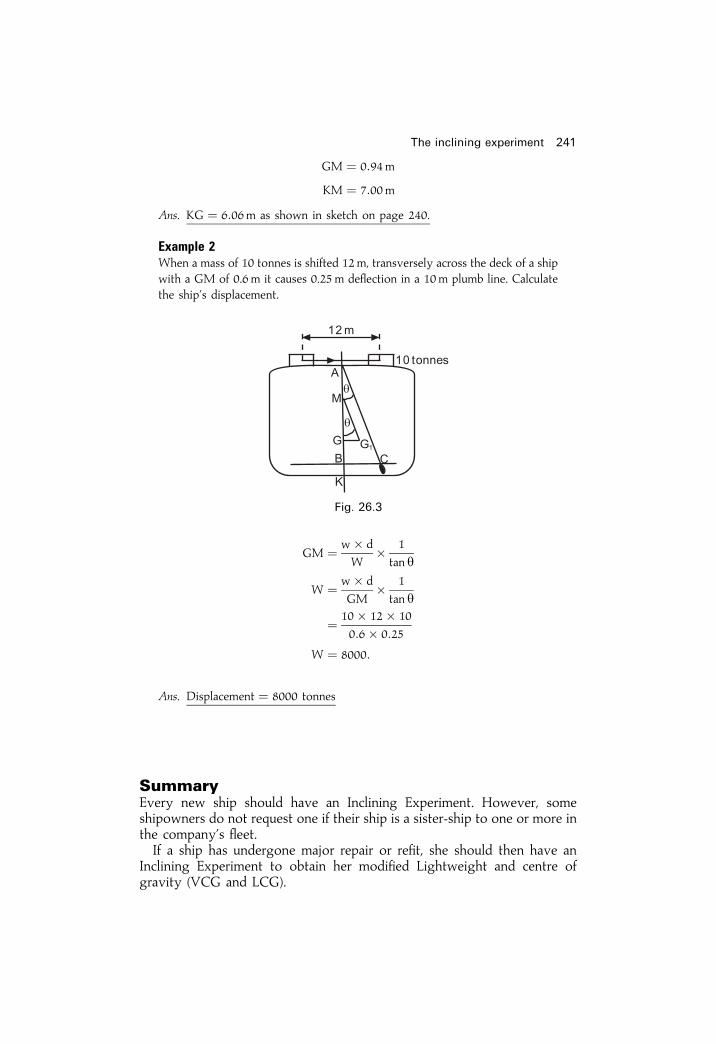
GM � 0:94m
KM � 7:00m
Ans. KG � 6:06m as shown in sketch on page 240.
Example 2When a mass of 10 tonnes is shifted 12m, transversely across the deck of a shipwith a GM of 0.6 m it causes 0.25m de¯ection in a 10m plumb line. Calculatethe ship's displacement.
GM � w� d
W� 1
tan y
W � w� d
GM� 1
tan y
� 10� 12� 10
0:6� 0:25
W � 8000:
Ans. Displacement � 8000 tonnes
SummaryEvery new ship should have an Inclining Experiment. However, someshipowners do not request one if their ship is a sister-ship to one or more inthe company's ¯eet.If a ship has undergone major repair or re®t, she should then have an
Inclining Experiment to obtain her modi®ed Lightweight and centre ofgravity (VCG and LCG).
The inclining experiment 241
Fig. 26.3

242 Ship Stability for Masters and Mates
Exercise 26
1 A ship of 8000 tonnes displacement has KM� 7.3 m and KG� 6.1 m. Amass of 25 tonnes is moved transversely across the deck through a distanceof 15m. Find the de¯ection of a plumb line which is 4 m long.
2 As a result of performing the inclining experiment it was found that a shiphad an initial metacentric height of 1m. A mass of 10 tonnes, when shifted12m transversely, had listed the ship 312 degrees and produced a de¯ectionof 0.25m in the plumb line. Find the ship's displacement and the length ofthe plumb line.
3 A ship has KM� 6.1 m and displacement of 3150 tonnes. When a mass of15 tonnes, already on board, is moved horizontally across the deck througha distance of 10m it causes 0.25m de¯ection in an 8m long plumb line.Calculate the ship's KG.
4 A ship has an initial GM� 0.5 m. When a mass of 25 tonnes is shiftedtransversely a distance of 10m across the deck, it causes a de¯ection of0.4m in a 4m plumb line. Find the ship's displacement.
5 A ship of 2304 tonnes displacement has an initial metacentric height of1.2m. Find the de¯ection in a plumb line which is suspended from a point7.2m above a batten when a mass of 15 tonnes, already on board, is shifted10m transversely across the deck.
6 During the course of an inclining experiment in a ship of 4000 tonnesdisplacement, it was found that, when a mass of 12 tonnes was movedtransversely across the deck, it caused a de¯ection of 75mm in a plumb linewhich was suspended from a point 7.5 m above the batten. KM� 10.2 m.KG� 7m. Find the distance through which the mass was moved.
7 A box-shaped vessel 60m� 10m� 3m is ¯oating upright in fresh wateron an even keel at 2m draft. When a mass of 15 tonnes is moved 6mtransversely across the deck a 6m plumb line is de¯ected 20 cm. Find theship's KG.
8 The transverse section of a barge is in the form of a triangle, apexdownwards. The ship's length is 65m, breadth at the waterline 8m, andthe vessel is ¯oating upright in salt water on an even keel at 4 m draft.When a mass of 13 tonnes is shifted 6m transversely it causes 20 cmde¯ection in a 3m plumb line. Find the vessel's KG,
9 A ship of 8000 tonnes displacement is inclined by moving 4 tonnestransversely through a distance of 19m. The average de¯ections of twopendulums, each 6m long, was 12 cm `Weights on' to complete this shipwere 75 t centred at Kg of 7.65m `Weights off' amounted to 25 t centred atKg of 8.16m.(a) Calculate the GM and angle of heel relating to this information, for the
ship as inclined.(b) From Hydrostatic Curves for this ship as inclined, the KM was 9m.
Calculate the ship's ®nal Lightweight and VCG at this weight.
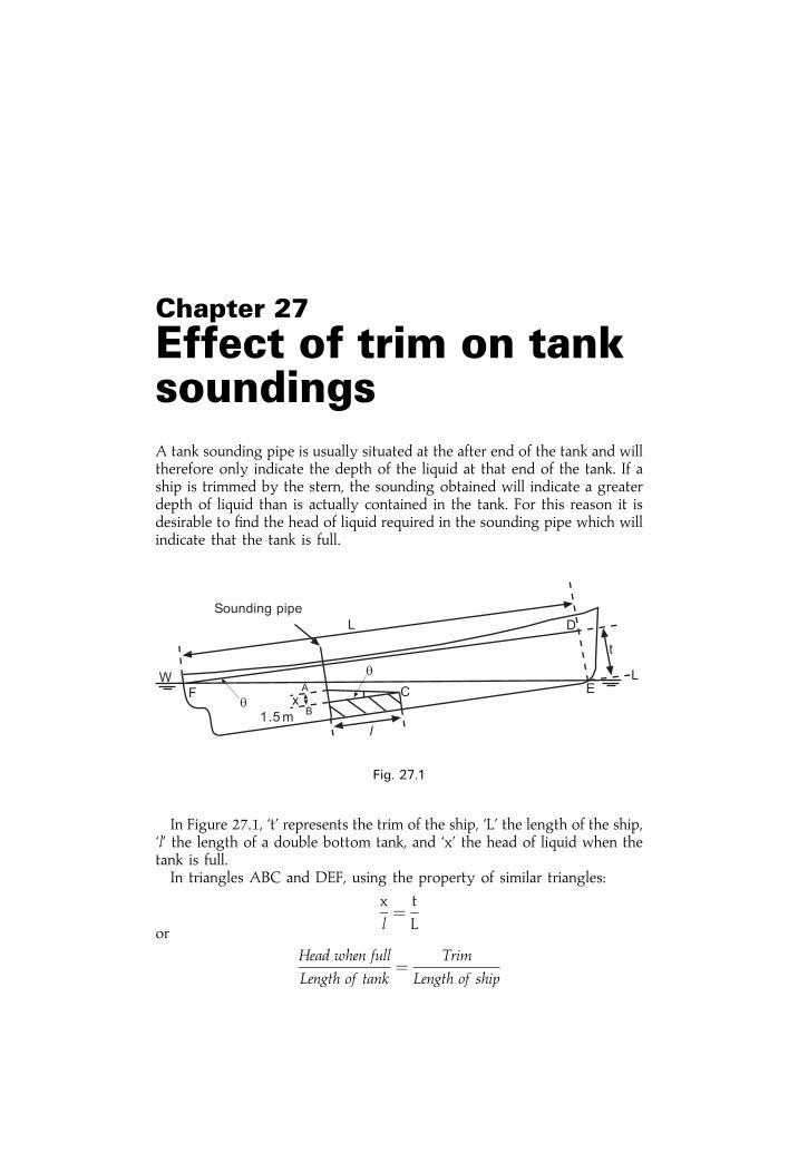
Chapter 27
Effect of trim on tanksoundingsA tank sounding pipe is usually situated at the after end of the tank and willtherefore only indicate the depth of the liquid at that end of the tank. If aship is trimmed by the stern, the sounding obtained will indicate a greaterdepth of liquid than is actually contained in the tank. For this reason it isdesirable to ®nd the head of liquid required in the sounding pipe which willindicate that the tank is full.
In Figure 27.1, `t' represents the trim of the ship, `L' the length of the ship,`l' the length of a double bottom tank, and `x' the head of liquid when thetank is full.In triangles ABC and DEF, using the property of similar triangles:
x
l� t
Lor
Head when full
Length of tank� Trim
Length of ship
Fig. 27.1

Example 1A ship 100m long is trimmed 1.5 m by the stern. A double bottom tank12m� 10m � 1.5 m has the sounding pipe at the after end. Find the soundingwhich will indicate that the tank is full.
Head
l� Trim
L
; Head when full � 1:5� 12
100
X or AB � 0:18m
Depth of tank � 1:50m
Ans. Sounding when full � 1:68m
Example 2A ship 100m long is trimmed 2m by the stern. A double bottom tank15m� 20m� 1.5 m, which has the sounding pipe situated at the after end, isbeing ®lled with fuel oil of relative density 0.8. The present tank sounding is1.6 m. Find the sounding when the tank is full, and also how much more oil isrequired to ®ll the tank.
In Figure 27.2 the right-angled triangles ABC, CDE, and BEF are similar.BG� 1.5 m. FG� the present sounding (1.6 m).
Head
l� Trim
L
Head � 2� 15
100
Head of oil full � 0:30m
; The sounding when full � 1:80m (AG)Also:
CD � Head of oil full N present tank sounding
� 1:80m N 1.60m
CD � 0:20m
244 Ship stability
Fig. 27.2
In triangles CED and ABC:
CE
CD� BC
AB
CE � CD� BC
AB
� 0:20
0:30� 15
CE � 10 metres
Volume of oil yet required � Area triangle CED� Breadth of tank
� 12� CE� CD� 20
� 12� 10� 0:20� 20
� 20 cu. m
Mass of oil required � Volume� density
� 20� 0:8
� 16 tonnes
Ans. Sounding when full 1.8m. Oil yet required 16 tonnes
Effect of trim on tank soundings 245
Exercise 27
1 A ship 120m long is trimmed 1.5 m by the stern. A double bottom tank is15m� 20m� 1m and has the sounding pipe situated at the after end ofthe tank. Find the sounding which will indicate that the tank is full.
2 A ship 120m long is trimmed 2m by the stern. A double bottom tank36m� 15m� 1m is being ®lled with fuel oil of relative density 0.96. Thesounding pipe is at the after end of the tank and the present sounding is1.2m. Find how many tonnes of oil are yet required to ®ll this tank and also®nd the sounding when the tank is full.

Chapter 28
Drydocking andgroundingWhen a ship enters a drydock she must have a positive initial GM, beupright, and trimmed slightly, usually by the stern. On entering thedrydock the ship is lined up with her centre line vertically over thecentre line of the keel blocks and the shores are placed loosely in position.The dock gates are then closed and pumping out commences. The rate ofpumping is reduced as the ship's stern post nears the blocks. When the sternlands on the blocks the shores are hardened up commencing from aft andgradually working forward so that all of the shores will be hardened up inposition by the time the ship takes the blocks overall. The rate of pumpingis then increased to quickly empty the dock.As the water level falls in the drydock there is no effect on the ship's
stability so long as the ship is completely waterborne, but after the sternlands on the blocks the draft aft will decrease and the trim will change bythe head. This will continue until the ship takes the blocks overallthroughout her length, when the draft will then decrease uniformly forwardand aft.The interval of time between the stern post landing on the blocks and the
ship taking the blocks overall is referred to as the critical period. During thisperiod part of the weight of the ship is being borne by the blocks, and thiscreates an upthrust at the stern which increases as the water level falls in thedrydock. The upthrust causes a virtual loss in metacentric height and it isessential that positive effective metacentric height be maintained through-out the critical period, or the ship will heel over and perhaps slip off theblocks with disastrous results.The purpose of this chapter is to show the methods by which the
effective metacentric height may be calculated for any instant during thedrydocking process.Figure 28.1 shows the longitudinal section of a ship during the critical
period. `P' is the upthrust at the stern and `l' is the distance of the centre of¯otation from aft. The trimming moment is given by P� l. But thetrimming moment is also equal to MCTC�Change of trim.

Therefore,P� l � MCTC� t
or,
P � MCTC� t
lwhere
P � the upthrust at the stern in tonnes,
t � the change of trim since entering the drydock in centimetres, and
l � the distance of the centre of flotation from aft in metres.
Now consider Figure 28.2 which shows a transverse section of the shipduring the critical period after she has been inclined to a small angle (ydegrees) by a force external to the ship. For the sake of clarity the angle ofheel has been magni®ed. The weight of the ship (W) acts downwardsthrough the centre of gravity (G). The force P acts upwards through thekeel (K) and is equal to the weight being borne by the blocks. Forequilibrium the force of buoyancy must now be (Wÿ P) and will actupwards through the initial metacentre (M).
Drydocking and grounding 247
Fig. 28.1
Fig. 28.2

There are, thus, three parallel forces to consider when calculating theeffect of the force P on the ship's stability. Two of these forces may bereplaced by their resultant (see page 4) in order to ®nd the effectivemetacentric height and the moment of statical stability.
Method (a)In Figure 28.3 consider the two parallel forces P and (Wÿ P). Theirresultant W will act upwards through M1 such that:
�Wÿ P� � y � P� Xor
�Wÿ P� �MM1 � sin y � P� KM1 � sin y
�Wÿ P� �MM1 � P� KM1
W�MM1 ÿ P�MM1 � P� KM1
W�MM1 � P� KM1 � P�MM1
� P �KM1 �MM1�� P� KM
MM1 � P� KM
W
There are now two forces to consider: W acting upwards through M1
and W acting downwards through G. These produce a righting moment ofW�GM1� sin y.Note also that the original metacentric height was GM but has now been
reduced to GM1. Therefore MM1 is the virtual loss of metacentric heightdue to drydocking.
248 Ship Stability for Masters and Mates
Fig. 28.3

��
������� �� � �� ����� � �� ��
�
������ ��� �� ���� ��� � �������� ���� � ��� � �� ������ ����� ������� ������ ��� � ��� ����� ������ !� ��� ����"
�� # � �� $
��� !!� � �� � � �� �!� � �� �
�� !!� � �� �!�
� � ��!� !!��� �� �!� �� !!�
�� !!� � �� !!� � �� �!
!!� ��� �� � �� �!
!!� � �� �!
�� �
����� ��� � � ���� � �� ����" ��� � ������ ����� �������% ��� ��� � ������ ����� ������ !�� ��� � ������ � ��������&&��� � ��� � �!��� �� ��
��� ������� &���������� ������ � !� '�� �� � '��� ������� �!��� �������� !!� � ��� (������ � � &���������� ������ ��� ���#��)����
�������� �� ����� ��
��� ���

��
������� �� � �� ����� � �� ��
�� �������� �� �� � ���� � ��� ����������� ����� � ���� �� ������� ���� �� ������� ��� �� �! ��� ��� �"#"� $� � ����� #� ������ � % ���� � �& � �� � ���� '��� �� �������(� ����������� ��)� �� �� �������� ������ ��� ���� �� ���� �� �� �� (������
���� �*�� ��� �� ���� �� �� �������� ������ � +�� �
� � �"#"� �
�
� $�� ��
& � � �� � ���
������ ��
,���*�� � � �� ����� � �� ��
�
� ��� ��
����
� ���� �
���)���� �� � �� � ��� � �� ���
��� -�. �� � ��&/ �
������ �
,���*�� � � �� � �� ��
�� �
��� � ��� �
$&�
� ������
���)���� �� � �� ������ -�. �� � ��&�$�
'� � ��� ��*�� �� . *�� ������ ��� ���� ��� �. � ���� ��.�� � ����� �� ����! �*� �� � � � �� ���� #� ��0 ������� � ���*�� � �� *���)�� ��������� �� �� ��)���) � ���� ��� � � �� �� �������(� ����������� ��)��� ���# ���*����� �� � ���! ����*���� �� ��)���) � ���� )�(�� �� ��� ��� �
.�� �� �� � ����� � � ���� ��)�� 1��2
������ ��
3�)���) � ���� � �� ��� � �� �
� ����� ��&/ � �� ��
� �4 �� �� ��� � �����
��� ���� ������� �� ������ �� ����

Method (b)Righting moment � �Wÿ P� � G1M� sin y
� 5940� 1:439� sin y�
� �8549� sin y� tonnes metres.Thus each of the two methods used gives a correct indication of the ship's
stability during the critical period.
Example 2A ship of 3000 tonnes displacement is 100m long, has KM� 6m, KG� 5.5 m.The centre of ¯otation is 2m aft of amidships. MCTC� 40 tonnesm. Find themaximum trim for the ship to enter a drydock if the metacentric height at thecritical instant before the ship takes the blocks forward and aft is to be not lessthan 0.3 m.
KM � 6:0m
KG � 5:5m
Original GM � 0:5m
Virtual GM � 0:3m
Virtual loss � 0:2m
Method (a)
Virtual loss of GM �MM1� � P� KM
W
or
P � Virtual loss�W
KM
� 0:2� 3000
6
Maximum P � 100 tonnes
But
P � MCTC� t
l
or
Maximum t � P� l
MCTC
� 100� 48
40
Ans. Maximum trim � 120 cm by the stern
Drydocking and grounding 251

Method (b)
Virtual loss of GM �GG1� � P� KG
Wÿ P
0:2 � P� 5:5
3000ÿ P
600ÿ 0:2 P � 5:5 P
5:7 P � 600
Maximum P � 600
5:7� 105:26 tonnes
But
P � MCTC� t
lor
Maximum t � P� l
MCTC
� 105:26� 48
40
Ans. Maximum trim � 126:3 cm by the stern
There are therefore two possible answers to this question, depending uponthe method of solution used. The reason for this is that although the effectivemetacentric height at the critical instant in each case will be the same, therighting moments at equal angles of heel will not be the same.
Example 3A ship of 5000 tonnes displacement enters a drydock trimmed 0.45m by thestern. KM� 7.5 m, KG� 6:0m. MCTC� 120 tonnes m. The centre of¯otation is 60m from aft. Find the effective metacentric height at the criticalinstant before the ship takes the blocks overall, assuming that the transversemetacentre rises 0.075m.
P � MCTC� t
l
� 120� 45
60
P � 90 tonnes
Method (a)
Virtual loss �MM1� � P� KM
W
� 90� 7:575
5000
� 0:136m
252 Ship Stability for Masters and Mates
Original KM � 7:500m
Rise of M � 0:075m
New KM � 7:575m
KG � 6:000m
GM � 1:575m
Virtual loss �MM1� � 0:136m
Ans. New GM � 1:439m
Method (b)
Virtual loss �GG1� � P� KG
Wÿ P
� 90� 6:0
4910
� 0:110m
Old KG � 6:000m
Virtual loss �GG1� � 0:110m
New KG � 6:110m
New KM � 7:575m
Ans. New GM � 1:465m
The virtual loss of GM after taking theblocks overallWhen a ship takes the blocks overall, the water level will then fall uniformlyabout the ship, and for each centimetre fallen by the water level P will beincreased by a number of tonnes equal to the TPC. Also, the force P at anytime during the operation will be equal to the difference between theweight of the ship and the weight of water she is displacing at that time.
Example 4A ship of 5000 tonnes displacement enters a drydock on an even keel.KM� 6m. KG� 5.5m, and TPC� 50 tonnes. Find the virtual loss ofmetacentric height after the ship has taken the blocks and the water hasfallen another 0.24m.
P � TPC� reduction in draft in cm
� 50� 24
P � 1200 tonnes
Drydocking and grounding 253

Method (a)
Virtual loss�MM1� � P� KM
W
� 1200� 6
5000Ans. Virtual loss � 1:44m
Method (b)
Virtual loss �GG1� � P� KG
Wÿ P
� 1200� 5:5
3800Ans. Virtual loss � 1:74m
Note to StudentsIn the D.Tp. examinations, when suf®cient information is given in aquestion, either method of solution may be used. It has been shown inthis chapter that both are equally correct. In some questions, however, thereis no choice, as the information given is suf®cient for only one of themethods to be used. It is therefore advisable for students to learn both ofthe methods.
Example 5A ship of 8000 tonnes displacement takes the ground on a sand bank on afalling tide at an even keel draft of 5.2 metres. KG 4.0 metres. The predicteddepth of water over the sand bank at the following low water is 3.2 metres.Calculate the GM at this time assuming that the KM will then be 5.0 metresand that the mean TPC is 15 tonnes.
P � TPC� Fall in water level (cm) � 15� (520ÿ 320)
� 15� 200
P � 3000 tonnes
Method (a)
Virtual loss of GM �MM1� � P� KM
W
� 3000� 5
8000
� 1:88m
Actual KM � 5:00m
Virtual KM � 3:12m
KG � 4:00mAns. New GM � ÿ0:88m
254 Ship Stability for Masters and Mates

Method (b)
Virtual loss of GM �GG1� � P� KG
Wÿ P
� 3000� 4
5000
� 2:40m
KG � 4:00m
Virtual KG � 6:40m
KM � 5:00m
Ans. New GM � ÿ1:40mNote that in Example 5, this vessel has developed a negative GM.
Consequently she is unstable. She would capsize if transverse external forcessuch as wind or waves were to remove her from zero angle of heel. Suggest achange of loading to reduce KG and make GM a positive value greater thatD.Tp. minimum of 0.15m.
Drydocking and grounding 255
EXERCISE 28
1 A ship being drydocked has a displacement of 1500 tonnes. TPC� 5tonnes, KM� 3.5 m, GM� 0.5m, and has taken the blocks fore and aft at3 m draft. Find the GM when the water level has fallen another 0.6m.
2 A ship of 4200 tonnes displacement has GM 0.75m and present drafts2.7m F and 3.7 m A. She is to enter a drydock. MCTC� 120 tonnes m.The after keel block is 60m aft of the centre of ¯otation. At 3.2 m meandraft KM� 8m. Find the GM on taking the blocks forward and aft.
3 A box-shaped vessel 150m long, 10m beam, and 5m deep, has a meandraft in salt water of 3 m and is trimmed 1m by the stern, KG� 3.5 m.State whether it is safe to drydock this vessel in this condition or not, andgive reasons for your answer.
4 A ship of 6000 tonnes displacement is 120m long and is trimmed 1m bythe stern. KG� 5.3 m, GM� 0,7 m. MCTC� 90 tonnes m. Is it safe todrydock the ship in this condition? (Assume that the centre of ¯otation isamidships.)
5 A ship of 4000 tonnes displacement, 126m long, has KM� 6.7m.KG� 6.1m. The centre of ¯otation is 3 m aft of amidships.MCTC� 120 tonnes m. Find the maximum trim at which the ship mayenter a drydock if the minimum GM at the critical instant is to be 0.3 m.

Chapter 29
Second moments ofareasThe second moment of an element of an area about an axis is equal to theproduct of the area and the square of its distance from the axis. Let dA inFigure 29.1 represent an element of an area and let y be its distance fromthe axis AB.The second moment of the element about AB is equal to dA� y2.
To ®nd the second moment of a rectangle about an axis parallel to one ofits sides and passing through the centroid.In Figure 29.2, l represents the length of the rectangle and b represents
the breadth. Let G be the centroid and let AB, an axis parallel to one of thesides, pass through the centroid.Consider the elementary strip which is shown shaded in the ®gure. The
second moment (i) of the strip about the axis AB is given by theequation:
i � lEdx� x2
Let IAB be the second moment of the whole rectangle about the axis ABthen:
Fig. 29.1

IAB ���b=2ÿb=2
lx2 dx
IAB � l
��b=2ÿb=2
x2 dx
� l
�x3
3
��b=2ÿb=2
IAB � lb3
12
To ®nd the second moment of a rectangle about one of its sides.Consider the second moment (i) of the elementary strip shown in Figure
29.3 about the axis AB.i � lEdx� x2
Let IAB be the second moment of the rectangle about the axis AB, then:
IAB ��bO
lx2 dx
� l
�x3
3
�bO
Second moments of areas 257
Fig. 29.2
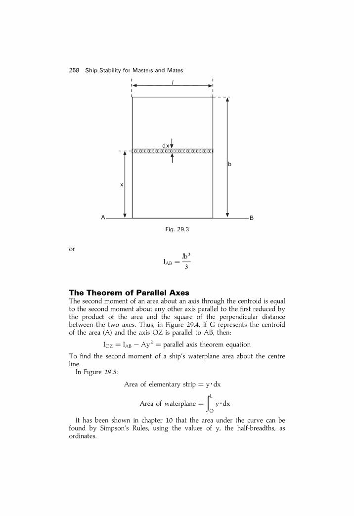
or
IAB � lb3
3
The Theorem of Parallel AxesThe second moment of an area about an axis through the centroid is equalto the second moment about any other axis parallel to the ®rst reduced bythe product of the area and the square of the perpendicular distancebetween the two axes. Thus, in Figure 29.4, if G represents the centroidof the area (A) and the axis OZ is parallel to AB, then:
IOZ � IAB ÿ Ay2 � parallel axis theorem equation
To ®nd the second moment of a ship's waterplane area about the centreline.In Figure 29.5:
Area of elementary strip � yEdx
Area of waterplane ��LO
yEdx
It has been shown in chapter 10 that the area under the curve can befound by Simpson's Rules, using the values of y, the half-breadths, asordinates.
258 Ship Stability for Masters and Mates
Fig. 29.3

The second moment of a rectangle about one end is given bylb3
3, and
therefore the second moment of the elementary strip about the centre line is
given by y3 dx3 and the second moment of the half waterplane about the
centre line is given by �LO
y3
3dx
Therefore, if ICL is the second moment of the whole waterplane area aboutthe centre line, then:
ICL � 2
3
�LO
y3 dx
Second moments of areas 259
Fig. 29.4
Fig. 29.5

The integral part of this expression can be evaluated by Simpson's Rulesusing the values of y3 (i.e. the half-breadths cubed), as ordinates, and ICL isfound by multiplying the result by 2
3.
Example 1A ship's waterplane is 18 metres long. The half-ordinates at equal distancesfrom forward are as follows:
0, 1.2, 1.5, 1.8, 1.8, 1.5, and 1.2 metres,
respectively. Find the second moment of the waterplane area about the centreline.
ICL � 2
9� CI� S1
ICL � 2
9� 18
6� 63:882
� 42:588m4
To ®nd the second moment of the waterplane area about a transverse axisthrough the centre of ¯otation.
Area of elementary strip � y dx
IAB of the elementary strip � x2 y dx
IAB of the waterplane area � 2
�LO
x2 y dx
Once again the integral part of this expression can be evaluated bySimpson's Rules using the values of x2 y as ordinates and the secondmoment about AB is found by multiplying the result by two.Let OZ be a transverse axis through the centre of ¯otation. The second
moment about OZ can then be found by the theorem of parallel axes. i.e.
IOZ � IAB ÿ A�X2
260 Ship Stability for Masters and Mates
12 ord.
12 ord.
3 S.M. Products for ICL
0 0 1 01.2 1.728 4 6.9121.5 3.375 2 6.7501.8 5.832 4 23.3281.8 5.832 2 11.6641.5 3.375 4 13.5001.2 1.728 1 1.728
63:882 � S1

Example 2A ship's waterplane is 18 metres long. The half-ordinates at equal distancesfrom forward are as follows:
0, 1.2, 1.5, 1.8, 1.8, 1.5, 1.2 metres, respectively.
Find the second moment of the waterplane area about a transverse axis throughthe centre of ¯otation.
Area of waterplane � 1
3� CI� S1 � 2
Area of waterplane � 1
3� 18
6� 25:8� 2
� 51:6 sq. m
Distance of the Centre of � S2
S1� CI
Flotation from forward
Second moments of areas 261
Fig. 29.6
12 ord. SM Area func Lever Moment func Lever Inertia func.
0 1 0 0 0 0 01.2 4 4.8 1 4.8 1 4.81.5 2 3.0 2 6.0 2 12.01.8 4 7.2 3 21.6 3 64.81.8 2 3.6 4 14.4 4 57.61.5 4 6.0 5 30.0 5 150.01.2 1 1.2 6 7.2 6 43.2
25:8 � S1 84:0 � S2 332:4 � S3

� 84
25:8� 18
6
� 9:77m
� 0:77m aft of amidships
IAB � 1
3� �CI�3 � S3 � 2
� 1
3��18
6
�3
� 332:4� 2 � 5983m4
IOZ � IAB ÿ A�X2
� 5983ÿ 51:6� 9:772
� 5983ÿ 4925
Ans. IOZ � 1058 metres4
There is a quicker and more ef®cient method of obtaining the solution to theabove problem. Instead of using the foremost ordinate at the datum, use themidship ordinate. Proceed as follows:
Area of waterplane � 1
3� S1 � h� 2 h � 18
6� 3m
� 1
3� 25:8� 3� 2
� 51:6m2 (as before)
S2 � �6:6The �ve sign shows Centre of Flotation is in aft body
Centre of Flotation from �e� � S2
S1� h
� � 6:6
25:8� 3
262 Ship Stability for Masters and Mates
12 ord. SM Area func. Lever�e� Moment func. Lever�e� Inertia func.
0 1 0 ÿ3 0 ÿ3 01.2 4 4.8 ÿ2 ÿ9:6 ÿ2 �19:21.5 2 3.0 ÿ1 ÿ3:0 ÿ1 �3:01.8 4 7.2 0 0 0 01.8 2 3.6 �1 �3:6 �1 �3:61.5 4 6.0 �2 �12:0 �2 �24:01.2 1 1.2 �3 �3:6 �3 �10:8
25:8 � S1 �6:6 � S2 60:6 � S3

; Centre of Flotation � �0:77m or 0.77m aft amidships (as before)
I�e� � 13� S3 � h3 � 2 � 1
3� 60:6� 33 � 2
; I�e� � 1090:8m4
But
ILCF � I�e� ÿ A�y � 1090:8ÿ �51:6� 0:772�� 1090:8ÿ 30:6
� 1060m4
i.e. very close to previous answer.With this improved method the levers are much less in value. Consequently
the error is decreased when predicting LCF�e� and ILCF.
SummaryWhen using Simpson Rules for second moments of area the procedureshould be as follows:
1 Make a sketch from the given information.2 Use a moment Table and insert values.3 Using summations obtained in the Table proceed to calculate area, LCF,I�e�, ILCF, ILc , etc.
4 Remember: sketch, table, calculation
Second moments of areas 263
264 Ship Stability for Masters and Mates
Exercise 29
1 A large square has a smaller square cut out of its centre such that thesecond moment of the smaller square about an axis parallel to one sideand passing through the centroid is the same as that of the portionremaining about the same axis. Find what proportion of the area of theoriginal square is cut out.
2 Find the second moment of a square of side 2a about its diagonals.3 Compare the second moment of a rectangle 40 cm� 30 cm about an axis
through the centroid and parallel to the 40 cm side with the secondmoment about an axis passing through the centroid and parallel to the30 cm side.
4 An H-girder is built from 5 cm thick steel plate. The central web is 25 cmhigh and the overall width of each of the horizontal ¯anges is 25 cm. Findthe second moment of the end section about an axis through the centroidand parallel to the horizontal ¯anges.
5 A ship's waterplane is 36m long. The half-ordinates, at equidistantintervals, commencing from forward, are as follows:
0, 4, 5, 6, 6, 5 and 4m respectively.
Calculate the second moment of the waterplane area about the centre lineand also about a transverse axis through the centre of ¯otation.
6 A ship's waterplane is 120 metres long. The half-ordinates at equidistantintervals from forward are as follows:
0, 3.7, 7.6, 7.6, 7.5, 4.6 and 0.1 m respectively.
Calculate the second moment of the waterplane area about the centre lineand about a transverse axis through the centre of ¯otation.
7 A ship of 12 000 tonnes displacement is 150 metres long at the waterline.The half-ordinates of the waterplane at equidistant intervals from forwardare as follows:
0, 4, 8.5. 11.6, 12.2, 12.5, 12.5, 11.6, 5.2, 2.4 and 0.3 m respectively.
Calculate the longitudinal and transverse BM's.8 The half-ordinates of a ship's waterplane at equidistant intervals from
forward are as follows:
0, 1.3, 5.2, 8.3, 9.7, 9.8, 8.3, 5.3, and 1.9m respectively.
If the common interval is 15.9 metres, ®nd the second moment of thewaterplane area about the centre line and a transverse axis through thecentre of ¯otation.
9 A ship's waterplane is 120 metres long. The half-ordinates commencingfrom aft are as follows:
0, 1.3, 3.7, 7.6, 7.6, 7.5, 4.6, 1.8 and 0.1 m respectively.
The spacing between the ®rst three and the last three half-ordinates is half

Second moments of areas 265
of that between the other half-ordinates. Calculate the second moment ofthe waterplane area about the centre line and about a transverse axisthrough the centre of ¯otation.
10 A ship's waterplane is 90 metres long between perpendiculars. The half-ordinates at this waterplane are as follows:
Station AP 12 1 2 3 4 5 512 FP
12 Ords. (m) 0 2 4.88 6.71 7.31 7.01 6.40 2 0.9
Calculate the second moment of the waterplane area about the centre lineand also about a transverse axis through the centre of ¯otation.

Chapter 30
Liquid pressure andthrust. Centres ofpressurePressure in liquidsWhen a ¯uid is in equilibrium the stress across any surface in it is normal tothe surface and the pressure intensity at any point of a ¯uid at rest is thesame in all directions. The pressure intensity in a homogeneous liquid atrest under gravity increases uniformly with depth. i.e.
P � w� g� Dwhere
P � Pressure intensity
w � Density of the liquid,
g � Acceleration due to gravity,and
D � Depth below the surface.
Total Thrust and Resultant ThrustIf the thrust on each element of area of a surface immersed in a ¯uid isfound, the scalar sum of all such thrusts is called the `Total Thrust' whilsttheir vector sum is called the `Resultant Thrust'. When the surface is planethen the Total Thrust is equal to the Resultant Thrust.
To ®nd the Resultant ThrustIn Figure 30.1, G represents the centroid of an area which is immersed,though not necessarily vertical, in a liquid, and Z represents the depth ofthe centroid of the area below the surface. Let w be the mass density of theliquid. If an element (dA) of the area, whose centroid is Z1 below thesurface, is considered, then:
Thrust on the element dA � Pressure intensity� Area
� w� g� Z1 � dA

Resultant thrust on the whole area are ��w� g� Z1 dA
� wg��Z1 dA
but �Z1 dA � ZEAE
and
w� g
�Z1 dA � w� gEZEAE
; Resultant thrust � Density� g� Depth of centroid� Area
It should be noted that this formula gives only the magnitude of theresultant thrust. It does not indicate the point at which the resultant thrustmay be considered to act.
The centre of pressureThe centre of pressure is the point at which the resultant thrust on animmersed surface may be considered to act. Its position may be found asfollows:
(i) For a rectangular lamina immersed with one side in the surface of the liquid.In Figure 30.2, each particle of the strip GH is approximately at the samedepth and therefore, the pressure intensity is nearly the same on eachparticle. Hence the resultant thrust on each strip will act at its mid-point.The resultant of the thrusts on all of the strips in the lamina will act at apoint on EF.
Liquid pressure and thrust. Centres of pressure 267
Fig. 30.1

Let w � Mass density of the liquid
The area of the elementary strip � b dx
The depth of the centroid of the strip below the surface is x if the plane ofthe rectangle is vertical, or x sin y if the plane is inclined at an angle y to thehorizontal.
The thrust on the strip � wEgEbExEsin yEdx
The resultant thrust on the lamina ��aO
wEgEbExEsin yEdx
� wEgEbEa2
2sin y
� aEbE� 12 EaEsin y� w� g
� Area� Depth of centroid
� g� Density
268 Ship Stability for Masters and Mates
Fig. 30.2

The moment of the thrust � wEgEbEx2Esin yEdxon the strip about AB
The moment of the ��aO
wEgEbEx2Esin ytotal thrust about AB
� wEgEbEa3
3Esin �
Let �X be the distance of the centre of pressure (P) from AB, then:
�X� Total thrust � Total moment about AB
�X� wEgEbEa2
2Esin y � wEgEb
a3
3Esin y
or�X � 2
3 a (unless sin y=0)
(ii) For any Plane Area immersed in a liquid.
In Figure 30.3, let OY be the line in which the plane cuts the surface ofthe liquid. Let the plane be inclined at an angle y to the horizontal.
Let h � the x co-ordinate of the centroid (G), and
let w � the mass density of the liquid.
Depth of the element dA � xEsin y
Thrust on dA � wEgExEsin yEdA
Moment of thrust about OY � wEgEx2Esin yEdA
Moment of total thrust about OY ��wEgEx2Esin yEdA
� wEgEsin yE�x2EdA
Liquid pressure and thrust. Centres of pressure 269
Fig. 30.3
Total thrust on A � wEgEAEDepth of centroid
� wEgEAEhEsin y
Moment of total thrust about OY � wEgEAEhEsin yE�X
; wEgEAEhEsin yE�X � wEgEsin yE�x2EdA
or
�X ��x2EdAhA
(Unless sin y � 0)
Let IOY be the second moment of the area about OY, then
IOY ��x2EdA
and�X � I OY
hA
or
�X � Second moment of area about the waterline
First moment of area about the waterline
Centres of pressure by Simpson's Rules
Using Horizontal OrdinatesReferring to Figure 30.4:
Thrust on the element � wEgExEyEdx
Moment of the thrust about OY � wEgEx2EyEdx
Moment of total thrust about OY ��wEgEx2EyEdx
� wEg�x2EyEdx
Total Thrust � wEgEAEDepth of centroid
� wEgE�yEdxE
�xEyEdx�yEdx
� wEgE�xEyEdx
Moment of total thrust about OY � Total Thrust� �X
270 Ship Stability for Masters and Mates

where�X � Depth of centre of pressure below the surface
; Moment of total thrust about OY � wEgE�xEyEdx� �X
or
wEgE�xEyEdx� �X � wEgE
�x2EyEdx
and
�X ��x2EyEdx�xEyEdx
The value of the expression�x2EyEdx can be found by Simpson's Rules
using values of the product x2y as ordinates, and the value of theexpression
�xEyEdx can be found in a similar manner using values of
the product xy as ordinates.
Example 1A lower hold bulkhead is 12 metres deep. The transverse widths of thebulkhead, commencing at the upper edge and spaced at 3m intervals, are asfollows:
15.4, 15.4, 15.4, 15.3 and 15m respectively.
Liquid pressure and thrust. Centres of pressure 271
Fig. 30.4

���� ��� ����� ��� ������ ��� ��� ���� ��� ���������� ���� ��� ��� � ���� � � ����� � ����� ���� ��� �� ��� ���������
���� � ��� �� �� � �
�� �����
� ��� ��
������! � ��!��� ���"#
$% � ��
��� �
� �&&��
���� �
� "�'��
�$( � �����
�) � *�'��
+,- � ��� �� � �� � �
�� �� � '*"�&
� �*����
+$% � +,- � � .$%/�0 ���� �������� �1� ������
+23 � +$% � ��)�
� +,- � � .$%� � �)�/
+23 � �*��� ����"�'�� � *�'���� �� '����
�4 � +23
��)
� �� '��
���� *�'�
�4 � '�"��
���� 5�� $����� 6�� ��� � '�" � ���� ��� ����������
��� ���� ������� � � ������� ��� �����
���� � ��� � ��� ��� ���� � ��� ��� ������ � ���
�"�� � �"�� � � � ��"�� � &��& � &��& � &��&�"�� � ���� � &��& � ������"�� � &��� � ����& � ""����"�� � �"�� � &��� � �����
����� � �� �&&�� � �� '*"�& � ��

Using vertical ordinatesReferring to Figure 30.6.
Thrust on the element � wEgEy
2EyEdx
� wEgEy2
2Edx
Moment of the thrust about OX � wEgEy2
2EdxE
2
3y
� wEgEy3
3Edx
Moment of total thrust about OX � w
3EgE
�y3Edx
Total Thrust � wEgEAEDepth at centre of gravity
� wEgE�yEdxE
12
�y2Edx�yEdx
� w
2EgE
�y2Edx
Liquid pressure and thrust. Centres of pressure 273
Fig. 30.5
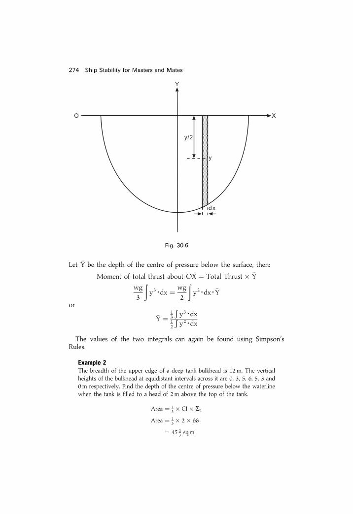
Let �Y be the depth of the centre of pressure below the surface, then:
Moment of total thrust about OX � Total Thrust� �Y
wg
3
�y3Edx � wg
2
�y2EdxE�Y
or
�Y �13
�y3Edx
12
�y2Edx
The values of the two integrals can again be found using Simpson'sRules.
Example 2The breadth of the upper edge of a deep tank bulkhead is 12m. The verticalheights of the bulkhead at equidistant intervals across it are 0, 3, 5, 6, 5, 3 and0m respectively. Find the depth of the centre of pressure below the waterlinewhen the tank is ®lled to a head of 2m above the top of the tank.
Area � 13� CI� S1
Area � 13� 2� 68
� 45 13 sqm
274 Ship Stability for Masters and Mates
Fig. 30.6

Referring to Figure 30.7:
CG � S2
S1� 1
2
� 316
68� 1
2
� 2:324m
CD � 2:000m
DG � 4:324m � �z
Liquid pressure and thrust. Centres of pressure 275
Ord, SM Area func. Ord. Moment func. Ord. Inertia func.
0 1 0 0 0 0 03 4 12 3 36 3 1085 2 10 5 50 5 2506 4 24 6 144 6 8645 2 10 5 50 5 2503 4 12 3 36 3 1080 1 0 0 0 0 0
68 � S1 316 � S2 1580 � S3
Fig. 30.7

��� � ��� ��� ��
� ��� �� �� � ���
��� � ��� � � �����
��� � ��� � ����
� ��� � � ����� � ����
� ��� � � ���� � ����
� ��� ��� ����� � � ��� ����� � �����
�� � ���
���
� ����
���� ���
�� � ���
���� ��� ������ �� ��!!"�� #! ��� $�%�& ��� &'���%#���
����������� "!#�( )#�*!��+! ,"%�! �� �!�#�'�� ��� '��' �� ' $"%-��'. "�.�� %#/"#.*��!!"�� ��(����� &#�� ��� 0�� '�. 1����� �� *��!!"�� ��� *��1�."��!��"%. $� '! ��%%�&!2
� 3'-� ' !-��1� ���� ��� (#4�� #�����'�#���� 3'-� ' �'$%� '�. #�!��� ��� ��%�4'�� ��.#�'��! '�. �"%�#*%#��!�� �'%1"%'�� ��� '��' �� $"%-��'.+! *%'�#�(� 5!�#�'�� ��� !�#*+! 0�� $�%�& ��� !�#*"%'��. .'�"� %�4�%� 6!#�( ��� *'�'%%�% '7#! �������8 1'%1"%'�� ��� ��/"�!��. 1����� ��*��!!"���
9 ,����$��2 !-��1�8 �'$%�8 1'%1"%'�#���
��� ���� ������� �� ������ �� ����

Liquid pressure and thrust. Centres of pressure 277
Exercise 30
1 A fore-peak tank bulkhead is 7.8 m deep. The widths at equidistant intervalsfrom its upper edge to the bottom are as follows:
16, 16.6, 17, 17.3, 16.3, 15.3 and 12m respectively.
Find the load on the bulkhead and the depth of the centre of pressure belowthe top of the bulkhead when the fore peak is ®lled with salt water to ahead of 1.3m above the crown of the tank.
2 A deep tank transverse bulkhead is 30m deep. Its width at equidistantintervals from the top to the bottom is:
20, 20.3, 20.5, 20.7, 18, 14 and 6m respectively.
Find the depth of the centre of pressure below the top of the bulkheadwhen the tank is ®lled to a head of 4 m above the top of the tank.
3 The transverse end bulkhead of a deep tank is 18m wide at its upper edge.The vertical depths of the bulkhead at equidistant intervals across it are asfollows:
0, 3.3, 5, 6, 5, 3.3 and 0m respectively.
Find the depth of the centre of pressure below the top of the bulkheadwhen the tank is ®lled with salt water to a head of 2m above the top of thebulkhead. Find also the load on the bulkhead.
4 A fore-peak bulkhead is 18m wide at its upper edge. Its vertical depth atthe centre line is 3.8 m. The vertical depths on each side of the centre line at3 m intervals are 3.5, 2.5 and 0.2 m respectively. Calculate the load on thebulkhead and the depth of the centre of pressure below the top of thebulkhead when the fore-peak tank is ®lled with salt water to a head of 4.5 mabove the top of the bulkhead.
5 The vertical ordinates across the end of a deep tank transverse bulkheadmeasured downwards from the top at equidistant intervals, are:
4, 6, 8, 9.5, 8, 6 and 4m respectively.
Find the distance of the centre of pressure below the top of the bulkheadwhen the tank is ®lled with salt water.
6 A square plate of side `a' is vertical and is immersed in water with an edgeof its length in the free surface. Prove that the distance between the centresof pressure of the two triangles into which the plate is divided by a
diagonal, isa�����13p8

Chapter 31
Ship squatWhat exactly is ship squat?When a ship proceeds through water, she pushes water ahead of her. Inorder not to have a `hole' in the water, this volume of water must returndown the sides and under the bottom of the ship. The streamlines of return¯ow are speeded up under the ship. This causes a drop in pressure, resultingin the ship dropping vertically in the water.As well as dropping vertically, the ship generally trims forward or aft.
The overall decrease in the static underkeel clearance, forward or aft, iscalled ship squat. It is not the difference between the draughts whenstationary and the draughts when the ship is moving ahead.If the ship moves forward at too great a speed when she is in shallow
water, say where this static even-keel underkeel clearance is 1.0 to 1.5 m,then grounding due to excessive squat could occur at the bow or at thestern.For full-form ships such as supertankers or OBO vessels, grounding will
occur generally at the bow. For ®ne-form vessels such as passenger liners orcontainer ships the grounding will generally occur at the stern. This isassuming that they are on even keel when stationary. It must be generally,because in the last two decades, several ship types have tended to beshorter in LBP and wider in Breadth Moulded. This has led to reportedgroundings due to ship squat at the bilge strakes at or near to amidshipswhen slight rolling motions have been present.Why has ship squat become so important in the last thirty years? Ship
squat has always existed on smaller and slower vessels when underway.These squats have only been a matter of centimetres and thus have beeninconsequential.However, from the mid-1960s to the late 1990s, ship size has steadily
grown until we have supertankers of the order of 350 000 tonnes dwt andabove. These supertankers have almost outgrown the ports they visit,resulting in small static even-keel underkeel clearances of 1.0 to 1.5 m.Alongside this development in ship size has been an increase in service

speed on several ships, for example container ships, where speeds havegradually increased from 16 knots up to about 25 knots.Ship design has seen tremendous changes in the 1980s and 1990s. In oil
tanker design we have the Jahre Viking with a dwt of 564 739 tonnes and anLBP of 440m. This is equivalent to the length of 9 football pitches. In 1997,the biggest container ship to date, namely the NYK Antares came intoservice. She has a dwt of 72 097 tonnes, a service speed of 23 kts., an LBP of283.8m; Br. Moulded of 40m; Draft Moulded of 13m; TEU of 5700, and afuel consumption of 190 tonnes/day.As the static underkeel clearances have decreased and as the service
speeds have increased, ship squats have gradually increased. They can nowbe of the order of 1.50 to 1.75m, which are of course by no meansinconsequential.To help focus the mind on the dangers of excessive squat one only has to
recall the recent grounding of four vessels:
In the United Kingdom, over the last 20 years the D.Tp. have showntheir concern by issuing four `M' notices concerning the problems of shipsquat and accompanying problems in shallow water. These alert all marinersto the associated dangers.Signs that a ship has entered shallow water conditions can be one or
more of the following:
1. Wave-making increases, especially at the forward end of the ship.2. Ship becomes more sluggish to manoeuvre. A pilot's quote, `almost like
being in porridge'.3. Draught indicators on the bridge or echo-sounders will indicate
changes in the end draughts.4. Propeller rpm indicator will show a decrease. If the ship is in `open
water' conditions, i.e. without breadth restrictions, this decrease may beup to 15 per cent of the service rpm in deep water. If the ship is in acon®ned channel, this decrease in rpm can be up to 20 per cent of theservice rpm.
5. There will be a drop in speed. If the ship is in open water conditionsthis decrease may be up to 30 per cent. If the ship is in a con®nedchannel such as a river or a canal then this decrease can be up to 60 percent.
6. The ship may start to vibrate suddenly. This is because of the entrainedwater effects causing the natural hull frequency to become resonantwith another frequency associated with the vessel.
Ship squat 279
Herald of Free Enterprise Ro-Ro vessel 06/03/87QEII Passenger liner 07/08/92Sea Empress Supertanker 15/02/96Diamond Grace 260 000 t. dwt VLCC at Tokyo 02/07/97
Harbour

7. Any rolling, pitching and heaving motions will all be reduced as theship moves from deep water to shallow water conditions. This isbecause of the cushioning effects produced by the narrow layer ofwater under the bottom shell of the vessel.
8. The appearance of mud could suddenly show in the water around theship's hull say in the event of passing over a raised shelf or asubmerged wreck.
9. Turning circle diameter (TCD) increases. TCD in shallow water couldincrease 100 per cent.
10. Stopping distances and stopping times increase, compared to when avessel is in deep waters.
What are the factors governing ship squat?The main factor is ship speed Vk. Squat varies approximately with thespeed squared. In other words, we can take as an example that if we halvethe speed we quarter the squat. In this context, speed Vk is the ship's speedrelative to the water; in other words, effect of current/tide speed with oragainst the ship must be taken into account.Another important factor is the block coef®cient Cb. Squat varies directly
with Cb. Oil tankers will therefore have comparatively more squat thanpassenger liners.The blockage factor `S' is another factor to consider. This is the immersed
cross-section of the ship's midship section divided by the cross-section ofwater within the canal or river. If the ship is in open water the width ofin¯uence of water can be calculated. This ranges from about 8.25b forsupertankers, to about 9.50b for general cargo ships, to about 11.75 ship-breadths for container ships.The presence of another ship in a narrow river will also affect squat, so
much so, that squats can double in value as they pass/cross the other vessel.Formulae have been developed that will be satisfactory for estimating
maximum ship squats for vessels operating in con®ned channels and inopen water conditions. These formulae are the results of analysing about600 results some measured on ships and some on ship models. Some of theemperical formulae developed are as follows:Let
b � breadth of ship.
B � breadth of river or canal.
H � depth of water.
T � ship's even-keel static draft.
Cb � block co-efficient.
Vk � ship speed relative to the water or current.
CSA � Cross Sectional Area. (See Fig. 31.3.)
280 Ship Stability for Masters and Mates
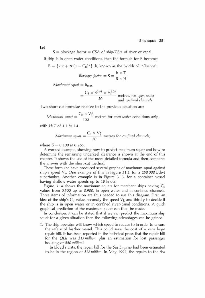
���� � ������ ���� � ��� �� �������� �� ��� � ����
�� ���� �� �� ���� ��� ����������� ���� ��� �� ��� �� � �������
� � ����� !�"� ��� �� �� ���� � ��� #����� �� ���������$�
�������� ���� � � � �� %
�� &
�� ���� ���� � ����
� �� � �!�'" � ( �!'
!��� ��� �� ���� ������ ������� ��������
%�� ��� �)��� �� ���� ������ �� ��� � ������ �*����� �+
�� ���� ���� � �� � (
"!!��� �� �� ���� ���� ���������� �����
���� ��� �� "�" � "�,�
�� ���� ���� � �� � (
-!��� �� �� ������� ���������
��� � � � !�"!! � !� .-�� �� �� �/����� ������� ��� �� � ����� �/���� �*�� �� ��� ��
���� ���� ��� ������� ���� ��� ��� ��� �� ����� � ��� ��� �� ��������� � �� ����� ��� ��� �� ��� �� � ������� �� ��� �� ���� ���� ����� ���� ���� ��� ��� �)��� �������%���� �� ���� ��� � ������ ���� � � ��� �� �/���� �*�� �����
����$� ����� (� 0�� �/���� �� ���� �� 1��� � 2"� � �� -! !!! �� ������� ��� � ������ �/���� �� �� 1��� � 2"�2� �� ������� ����������� ������ ��� ������ �� �� "' �����1��� � 2"�, ����� ��� �/���� �*��� �� �� ���� ����� ����� ��
����� � �� !�-!! �� �� !�3!!� �� ���� ��� �� �� ���4��� ��������%� �� ����� �� ���� ����� � ���� ������ �� ��� ���� ��� �� 1� ��� ���� �� ��� ����$� �� ����� �������5 ��� ����� (� �� ��� ��5 �� ������ ����� ���� �� �� ���� ��� � �� ���4��� ��� ���� ����������� � *���� ����� � �������� �� ��� �/���� �*�� �� ���� �� ������ ����������� �� �� �� ����� ��� �� �� �� � ����� ��� �/���� ����
�*�� �� ����� �������� ���� ��� ��������� ������� �� �� �����+
"� %�� ���� ��� �� ���� ��� ����� ����� �� ����� �� �� � �� �� ���� ���� ����5 �� ������ ������� %��� ����� ��� ��� ���� �� �� 5 � �� ��� ����� �� �� ���� ��� ��� �� ��� �������� � ��� ��� ��� ��� ������ ��� ���� �� !" �������� ���� � ��������� �� ���� ������� ������ �� #$ �������66
�� ���5�$� ������ ��� ��� ���� �� ��� ��� ������� �� ���� ���������� �� �� ��� ����� �� %& �������� �� 75 "33�� ��� ��� � �� ��� ���
���� ���� ��

Empress were completed at Harland & Wolff Ltd of Belfast, for areported cost of £20million. Rate of exchange in May 1997 was theorder of £1� $1.55. She was then renamed the Sea Spirit.
2. The ship of®cers could load the ship up an extra few centimetres (exceptof course where load-line limits would be exceeded). If a 100 000 tonnedwt tanker is loaded by an extra 30 cm or an SD14 general cargo ship isloaded by an extra 20 cm, the effect is an extra 3 per cent onto their dwt.This gives these ships extra earning capacity.
3. If the ship grounds due to excessive squatting in shallow water, thenapart from the large repair bill, there is the time the ship is `out ofservice'. Being `out of service' is indeed very costly because loss ofearnings can be as high as £100 000 per day.
4. When a vessel goes aground their is always a possibility of leakage ofoil resulting in compensation claims for oil pollution and fees for clean-up operations following the incident. These costs eventually may haveto be paid for by the shipowner.
These last four paragraphs illustrate very clearly that not knowing aboutship squat can prove to be very costly indeed. Remember, in a marine courthearing, ignorance is not acceptable as a legitimate excuse!!Summarizing, it can be stated that because maximum ship squat can now
be predicted, it has removed the `grey area' surrounding the phenomenon.In the past ship pilots have used `trial and error', `rule of thumb' and years ofexperience to bring their vessels safely in and out of port.Empirical formulae quoted in this study, modi®ed and re®ned over a
period of 25 years' research on the topic, give ®rm guidelines. Bymaintaining the ship's trading availability a shipowner's pro®t marginsare not decreased. More important still, this research can help prevent lossof life as occurred with the Herald of Free Enterprise grounding.It should be remembered that the quickest method for reducing the
danger of grounding due to ship squat is to reduce the ship's speed.`Prevention is better than cure' and much cheaper.
282 Ship Stability for Masters and Mates
Fig. 31.1. Ship in a canal in static condition.

�� � ����������� �� � � � ���� �� � �� ��
�� � ����������� �� ����� � �� ��
�������� ����� � � � ��
��� �� �
�� ��
�� � ��� ��������� �����������
������ � ���� � �����
�������� ����� ����� � ����� � �� !"�
#� �� �������� � $� � %&�'���� (�)� � ���� *����
+� � ����� �� � � ����'� � � *���, � �����
�* � �� � ��
(�) � -�-� ���� ��� � � ����� �
���� ���� ��
��� ���� ������� ����� ������ ���� ����� ��� ����� � �� �����������
��� ����
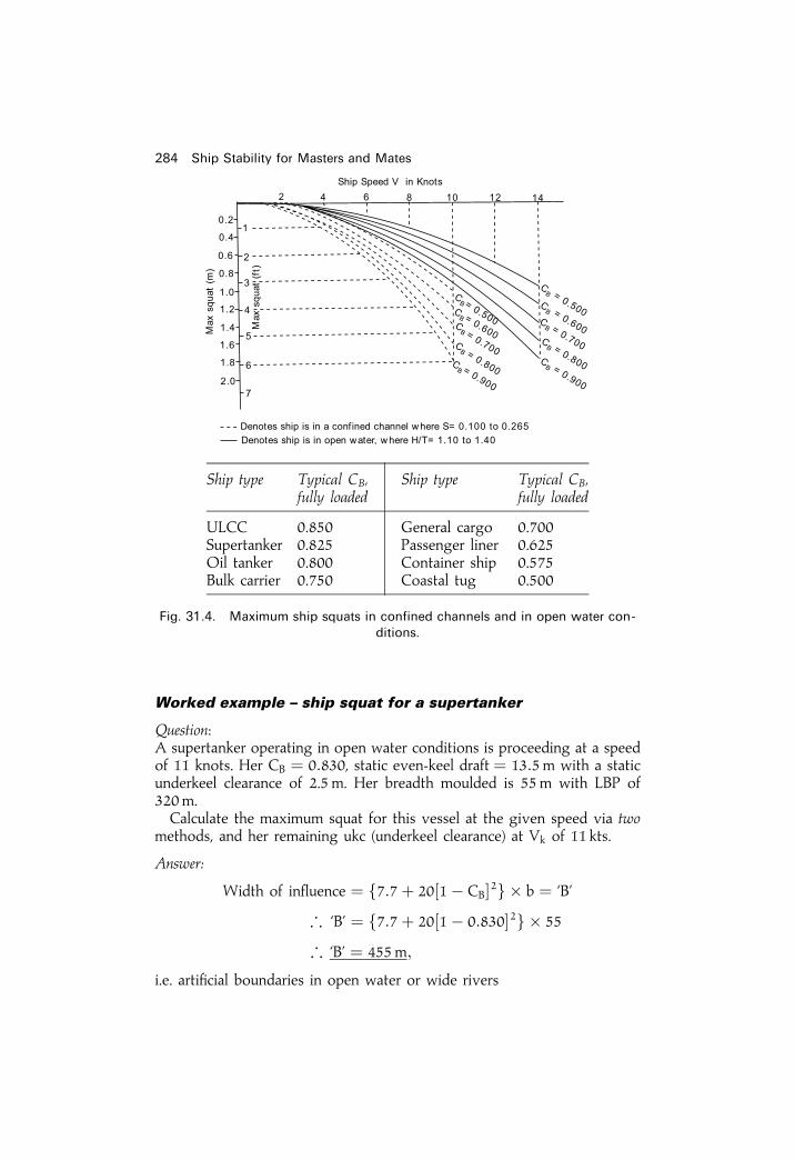
������ ����� � �� ���� ��� � ���������
���������� ��������� ����� � ��� ���� ��� � �� � ������� � � ������� �� ����� ��� �� � ������ ��� � �������� ����� ���� � �! ��� ��������� ������ �� "�� � ��� #����! ������ � �� � �! $�% ���"� �������� �!� & � �'�� ��� �! � ������ � �!� � �� ����� � ��
��!���� � !�� �� � ��� (�������� ������) � *� �� �� ����
�����
+ ��! �� ������ � �,�,� "���� ���"� � # � -�.� -�. � �,�,� "���� ������"� � ��� -�. � /�� �
��� �� 0� � #���� �� ��� ���� �� � �� � ����
��� ���� ������� �� ������ �� ����
��� ���� ������� ��� ��� ���� ������� �������� ������ ����� ������
1$�� ����� 2���� ���� ��,��3�������� ���"� %������ � �� ��4"�5 � ���� ����� ��� �� �! � ���,����� ��� �� ��,�� ����� ��� �����
���� ����� ������ ���� ����� �� ������� ������� �� �� ���� ��� ���!
��������

�������� ����� � �� ����� � �
��� �������� ������ ���� � �����
����� �����
������ ��
���� ! "#!� � $� � ��%� � &���%�
��� � ��
� � �� � ��%��� �������%� � �����% � �
��
� ���� � ��'( �� �� ���� ����!"� $� � ��)��*
������ � � ���+�� ������* �� !��
� �� � $� � &��
��� ���"
� � �� � ��%��� ���
���� ���� ,
�*�* "�����- ���.� ���.��!" �/"���� "� �.���������/� �/ �� ���� ����*
0.����� � �� � ��'(� ����
� ��'% -� � ���� ��/��� �� ��/�/� !/������� ������/�� � ���� -� � � �� � -�*
� -� � ������ ��'% � ���� 1 &� � �� �"*
���� ���� ��

��� ���� ������� �� ������ �� ����
�������� �
� � ������� ��� �� � ����� �� � � ��� �� ���������� �� � ������ � �� ����� ���� � �� �� ����� ���� � ������ ����� ���� �� ��������� �� ��� �� ����� �� !� �� � �� �� ��� �� �"�� �# ���� ��� �����������$%�& '���� �� ��( �� �� ���� ��� ���%)& ������� ������%�& *�+�� � �, ��- ������� ���� ������� �� �� ��� ��%�& ./������� ���� ������ ��� ������ �� ���� ��+�� � �, ���
� � ���� ��� �� ��������� ���� ���$��*�� �� ���� . �� �� ��� �� �� �� ����� �� �� �� ��0��� '���� ����� �� �� �� ����� 1����� ����� ���� �� ����� ��%�& 2�� ���� ��� �� � ����� �� � 3���4�� ������5 ��� ������%)& .�� � �� � �� ��+�� � �, �� ������� ��� � � �� � ��� ��� �� �� �� ����%�& 6� ���� ����� ���� �� �/������� ���� ������ �� ��� �� )
��� ���� ������.���� �� ������/ ��� ������������/ �� ��+�� � � � �� ���������� ���� ���� � �� ��� �� �� �� ��� �� ���� , �����
� � �� ��� ���� ��� ��� ���� ��� �� ��������� ���� ���$��*�� �� ������� 1����� ����� ���� �� ���� �� �� �� ��0��� . �� ����� �� �"�0��� '���� �� �� �� �07�� ���� ��� �� ����� � � �������- � �� ��� �, ��- ���� ���� �� �� 8 �� �� ��� �� �� �� )���

Chapter 32
Heel due to turningWhen a body moves in a circular path there is an acceleration towards thecentre equal to v2/r where v represents the velocity of the body and rrepresents the radius of the circular path. The force required to produce this
acceleration, called a `Centripetal' force, is equal toMv2
r, where M is the
mass of the body.In the case of a ship turning in a circle, the centripetal force is produced
by the water acting on the side of the ship away from the centre of the turn.The force is considered to act at the centre of lateral resistance which, in thiscase, is the centroid of the underwater area of the ship's side away from thecentre of the turn. The centroid of this area is considered to be at the levelof the centre of buoyancy. For equilibrium there must be an equal andopposite force, called the `Centrifugal' force, and this force is considered toact at the centre of mass (G).When a ship's rudder is put over to port, the forces on the rudder itself
will cause the ship to develop a small angle of heel initially to port, say a�1.However, the underwater form of the ship and centrifugal force on it
cause the ship to heel to starboard, say a�2.In this situation a�2 is always greater than a�1. Consequently for port
rudder helm, the ®nal angle of heel due to turning will be to starboard andvice versa.It can be seen from Figure 32.1 that these two forces produce a couple
which tends to heel the ship away from the centre of the turn. i.e.
Heeling couple � Mv2
r� B1Z
Equilibrium is produced by a righting couple equal to W�GZ, where W isequal to the weight of the ship, the weight being a unit of force, i.e.W�Mg.
;MEg� GZ � MEv2
r� B1Z

or
GZ � v2
gEr� B1Z
but at a small angleGZ � GMEsin y
andB1Z � BGEcos y
; GM sin y � v2
gErBGEcos y
and
tan y � v2 � BG
gErEGM
ExampleA ship turns to port in a circle of radius 100m at a speed of 15 knots. The GMis 0.67m and BG is 1m. If g� 981 cm/sec2 and 1 knot is equal to 1852 km/hour, ®nd the heel due to turning.
Ship speed in m/sec � 15� 1852
3600
v � 7:72m/sec
tan y � v2 � BG
gErEGM
288 Ship Stability for Masters and Mates
Fig. 32.1

� 7:722 � 1:0
9:81� 100� 0:67
tan y � 0:0907
Ans. Heel � 5� 110 to starboard, due to Contrifugal forces only
In practice, this angle of heel will be slightly smaller. Forces on the rudder willhave produced an angle of heel, say 1� 17 0 to port. Consequently the overallangle of heel due to turning will be:
Heel � 5� 110 ÿ 1� 17 0 � 3� 54 0 or 3:9� to starboard
Heel due to turning 289
Exercise 32
1 A ship's speed is 12 knots. The helm is put hard over and the ship turns in acircle of radius 488m. GM� 0.3 m and BG� 3m. Assuming that 1 knot isequal to 1852 km/hour, ®nd the heel due to turning.
2 A ship steaming at 10 knots turns in a circle of radius 366m. GM� 0.24m.BM� 3.7 m. Calculate the heel produced.
3 A ship turns in a circle of radius 100m at a speed of 15 knots. BG� 1m.Find the heel if the GM� 0.6 m.
4 A ship with a transverse metacentric height of 0.40m has a speed of 21 kts.The centre of gravity is 6.2m above keel whilst the centre of lateralresistance is 4.0 m above keel. The rudder is put hard over to port and thevessel turns in a circle of 550m radius.
Considering only the centrifugal forces involved, calculate the angle ofheel as this ship turns at the given speed.

Chapter 33
Unresisted rolling instill waterA ship will not normally roll in still water but if a study be made of suchrolling some important conclusions may be reached. For this study it isassumed that the amplitude of the roll is small and that the ship has positiveinitial metacentric height. Under the conditions rolling is considered to besimple harmonic motion so it will be necessary to consider brie¯y theprinciple of such motion.Let XOY in Figure 33.1 be a diameter of the circle whose radius is `r' and
let OA be a radius vector which rotates about O from position OY at aconstant angular velocity of `w' radians per second. Let P be the projectionof the point A on to the diameter XOY. Then, as the radius vector rotates,the point P will oscillate backwards and forwards between Y and X. Themotion of the point P is called `Simple Harmonic'.
Fig. 33.1

Let the radius vector rotate from OY to OA in `t' seconds, then angleAOY is equal to `wt'. Let the time taken for the radius vector to rotatethrough one complete revolution (2p radians) be equal to `T' seconds, then:
2p � wTor
T � 2p=w
LetOP � x
thenx � r cos wt
dx
dt� ÿrw sinwt
d2x
dt2� ÿrw2 cos wt
butr cos wt � x
;d2x
dt2� ÿw2x
ord2x
dt2� w2x � 0
The latter equation is the type of differential equation for simpleharmonic motion and since T� 2p/w and `w' is the square root of thecoef®cient of x in the above equation, then
T � 2p��������������������coeff. of xp
When a ship rolls, the axis about which the oscillation takes place cannotbe accurately determined but it would appear to be near to the longitudinalaxis through the ship's centre of gravity. Hence the ship rotates or rollsabout her `G'.The mass moment of inertia (I) of the ship about this axis is given by:
I � MEK2
whereM � The ship's mass, and
K � The radius of gyration about this axis.But
M � W
g
Unresisted rolling in still water 291

whereW � the ship's weight, andg � the acceleration due to gravity.
; I � W
gK2
When a ship is inclined to a small angle (y) the righting moment is givenby:
Righting moment � W� GZ
whereW � the ship's Weight, and
GZ � the righting lever.But
GZ � GMEsin y
; Righting moment � W� GM� sin y
And since y is a small angle, then:
Righting moment � W� GM� y
The angular acceleration � d2 ydt2
; I� d2 ydt2� ÿW� GZ
or
W
gEK2 � d2 y
dt2� ÿW� GM� y
W
gEK2 � d2 y
dt2�W� GM� y � 0
d2 ydt2� gEGMEy
K2� 0
This is the equation for a simple harmonic motion having a period `T'given by the equation:
T � 2p���������������������Coeff. of yp
or
T � 2pK�������������gEGMp � 2 pC���
gpC �
K��������GMp � 2K��������
GMp approx.
292 Ship stability

From the above it can be seen that:
1 The time period of roll is completely independent of the actual amplitudeof the roll so long as it is a small angle.
2 The time period of roll varies directly as K, the radius of gyration. Henceif the radius of gyration is increased, then the time period is alsoincreased. K may be increased by moving weights away from the axisof oscillation. Average K value is about 0:35� Br.Mld.
3 The time period of roll varies inversely as the square root of the initialmetacentric height. Therefore ships with a large GM will have a shortperiod and those with a small GM will have a long period.
4 The time period of roll will change when weights are loaded, discharged,or shifted within a ship, as this usually affects both the radius of gyrationand the initial metacentric height.
Example 1Find the still water period of roll for a ship when the radius of gyration is 6 mand the metacentric height is 0.5 m.
T � 2pK�������������gEGMp
T � 2pK��������������������9:81� 0:5p
� 2K����������GMT
p approx.
� 2� 6������0:5p approx.
� 16:97 s. Average � 17 s.
(99.71 per cent correct giving only 0.29 per cent error!!)
Ans. T � 17:02 sNote. In the S.I. system of units the value of g to be used in problems is 9.81 mper second per second, unless another speci®c value is given.
Example 2A ship of 10 000 tonnes displacement has GM� 0.5m. The period of roll instill water is 20 seconds. Find the new period of roll if a mass of 50 tonnes isdischarged from a position 14m above the centre of gravity. Assume
g � 9:81m/sec2
W2 � W0 ÿ w � 10 000ÿ 50 � 9950 tonnes
T � 2pK�������������gEGMp
20 � 2pK��������������������9:81� 0:5p
400 � 4Ep2EK2
9:81� 0:5
GG1 � w� d
W2
� 50� 14
9950
GG1 � 0:07m
GM � 0:50m
New GM � 0:57m
Unresisted rolling in still water 293
ä
ä
ä

��
�� � ���� ���� ��
�� ��
� �����
� � � ���
������������ � ����
� � � ���� �����
� � ��� ��� ���������
�� ���������� ���� � �!� " � �� ��
� ���� ���������
#�$ �� ���% � �!� ��� �������� & �� " � �������� � �� ���������� ����
� ��� ���� ����
� ��� �� ���������
'� ��� (������ �� %������� �)��*+��
� � #�$ �� ���% � �!�
��� ��$ & �� "� #�$ �� ���% � �!�
��� �������� & �� "�,� ""�
� � ��� ��� ���� �����
� � ��� ��� ��
� � ��� � ���������
� � ������
� #�$ �� � ���
� ��� �
��� �
���+��
�� � #�$ � ������������������� �
���
��� � ��
+��
(� � #�$ ( � ���������������������"��
�
(� � ������������������������������ ����
���- (� � ��� �
��� ���� �����

Procedure steps for Example 21 Calculate the new displacement in tonnes (W2).2 Estimate the original radius of gyration (K).3 Evaluate the new displacement and new GM (W2 and GM2).4 Calculate the new mass moment of inertia (I2).5 Calculate the new radius of gyration (K2).6 Finally evaluate the new period of roll (T2).
For `stiff ships' the period of roll could be as low as 8 seconds due to a largeGM. For `tender ships' the period of roll will be, say, 30 to 35 seconds, dueto a small GM. A good comfortable period of roll for those on board shipwill be 20 to 25 seconds.
Unresisted rolling in still water 295
Exercise 33
1 Find the still water period of roll for a ship when the radius of gyration is5 m and the initial metacentric height is 0.25m.
2 A ship of 5000 tonnes displacement has GM� 0.5 m. The still water periodof roll is 20 seconds. Find the new period of roll when a mass of 100 tonnesis discharged from a position 14m above the centre of gravity.
3 A ship of 9900 tonnes displacement has GM� 1m, and a still water rollingperiod of 15 seconds. Calculate the new rolling period when a mass of 100tonnes is loaded at a position 10m above the ship's centre of gravity.
4 A vessel has the following particulars:Displacement is 9000 tonnes, natural rolling period is TR of 15 seconds,GM is 1.20m. Determine the new natural rolling period after the followingchanges in loading have taken place:
2000 tonnes added at 4.0 m above ship's VCG.500 tonnes discharged at 3.0m below ship's VCG.
Assume that KM remains at the same value before and after changes ofloading have been completed. Discuss if this ®nal condition results in a `stiffship' or a `tender ship'.

Chapter 34
List due to bilging sidecompartmentsWhen a compartment in a ship is bilged the buoyancy provided by thatcompartment is lost. This causes the centre of buoyancy of the ship tomove directly away from the centre of the lost buoyancy and, unless thecentre of gravity of the compartment is on the ship's centre line, a listingmoment will be created, b� w.Let the ship in Figure 34.1 ¯oat upright at the waterline WL. G represents
the position of the ship's centre of gravity and B the centre of buoyancy.Now let a compartment which is divided at the centre line be bilged on
the starboard side as shown in the ®gure. To make good the lost buoyancy
Fig. 34.1

the ship will sink to the waterline W1L1. That is, the lost buoyancy is madegood by the layer between WL and W1L1.The centre of buouancy will move from B to B1, directly away from the
centre of gravity of the lost buoyancy, and the distance BB1 is equal tow� d
W, where w represents the lost buoyancy and d represents the distance
between the ship's centre of buoyancy and the centre of the lost buoyancy.The shift in the centre of buoyancy produces a listing moment.Let y be the resultant list.Then
tan y � GX=XM
� BB1=XM
where XM represents the initial metacentric height for the bilged condition.
Example 1A box-shaped vessel of length 100m and breadth 18m, ¯oats in salt water onan even keel at 7.5 m draft. KG� 4m. The ship has a continuous centre linebulkhead which is watertight. Find the list if a compartment amidships, which is15m long and is empty, is bilged on one side.
(a) Find the New Mean Draft
Bodily increase in draft � Volume of lost buoyancy
Area of intact W.P.
� 15� 9� 7:5
100� 18ÿ 15� 9� 0:61
New draft � 7:50� 0:61
; New draft � 8:11m � draft d2
List due to bilging side components 297
Fig. 34.2

(b) Find the Shift of the Centre of Buoyancy
BB1 � a� B=4
LBÿ a
� 15� 9� 18=4
100� 18ÿ 15� 9� 607:5
1665
� 0:37m
(c) To Find IOZ
ICL ��B
2
�3
EL
3��B
2
�3
E�Lÿ l�
3
ICL � 93 � 100
3� 93 � 85
3� 24 300� 20 655
� 44 955m4
IOZ � ICL ÿ AEBB21
� 44 955ÿ �100� 18ÿ 15� 9� � 0:3652
� 44 955ÿ 222
� 44 733m4
(d) To Find GM
BM � IOZ
V
� 44 733
100� 18� 7:5� 3:31m
�KB � d2
2; KB � 4:06m
KM � 7:37m
ÿKG � 4:00m as before bilging
After bilging, GM � 3:37m
(e) To Find the List
tan List � BB1GM
� 0:37
3:37� 0:1098
Ans. List � 6� 160
Example 2A box-shaped vessel, 50m long� 10m wide, ¯oats in salt water on an evenkeel at a draft of 4 m. A centre line longitudinal watertight bulkhead extends
298 Ship Stability for Masters and Mates

from end to end and for the full depth of the vessel. A compartment amidshipson the starboard side is 15m long and contains cargo with permeability `m' of30 per cent. Calculate the list if this compartment is bilged. KG� 3m.
(a) Find the New Mean Draft
Bodily increase in draft � Volume of lost buoyancy
Area of intact W.P.
�30
100� 15� 5� 4
50� 10ÿ 30
100� 15� 5
� 90
477:5
� 0:19m
; New draft � 4:00� 0:19 � 4:19m say draft d2
(b) Find the Shift of the Centre of Buoyancy
BB1 �ma� B
4LBÿ ma
�30
100� 15� 5� 10
4
50� 10ÿ 30
100� 15� 5
� 56:25
477:5
� 0:12m(c) To Find IOZ
ICL � LB3
12ÿ mlb3
3
� 50� 103
12ÿ 30
100� 15� 53
3
� 4166:7ÿ 187:5
� 3979m4
List due to bilging side components 299
Fig. 34.3

IOZ � ICL ÿ AEBB21
� 3979ÿ 477:5� 0:122
� 3979ÿ 7
� 3972m4
(d) To Find GM
BM2 � IOZ
V
BM2 � 3972
50� 10� 4; BM2 � 1:99m
�KB2 � 2:10m
KM2 � 4:09m
ÿas before bilging, KG � 3:00m
GM2 � 1:09m
(e) To Find the List
tan List � BB1=GM
� 0:12
1:09� 0:1101
Ans. List � 6� 170 to starboardNote: When m � 100 per cent then:
ICL ��B
2
�3
EL
3��B
2
�3�Lÿ l
3
�m4
or
ICL � LB3
12ÿ lb3
3m4
Both formulae give the same answer
Summary1 Make a sketch from the given information.2 Calculate the mean bodily increase in draft.3 Calculate the ship in the centre of buoyancy.4 Estimate the second moment of area in the bilged condition with the useof the parallel axis theorem.
5 Evaluate the new KB, BM, KM and GM.6 Finally calculate the requested angle of list.
300 Ship Stability for Masters and Mates

List due to bilging side components 301
Exercise 34
1 A box-shaped tanker barge is 100m long, 15m wide and ¯oats in salt wateron an even keel at 5 m draft. KG� 3m. The barge is divided longitudinallyby a centre line watertight bulkhead. An empty compartment amidships onthe starboard side is 10m long. Find the list if this compartment is bilged.
2 A box-shaped vessel, 80m long and 10m wide, is ¯oating on an even keelat 5 m draft. Find the list if a compartment amidships, 15m long is bilgedon one side of the centre line bulkhead. KG� 3m.
3 A box-shaped vessel, 120m long and 24m wide, ¯oats on an even keel insalt water at a draft of 7 m. KG� 7m. A compartment amidships is 12mlong and is divided at the centre line by a full depth watertight bulkhead.Calculate the list if this compartment is bilged.
4 A box-shaped vessel is 50m long, 10m wide and is divided longitudinallyat the centre line by a watertight bulkhead. The vessel ¯oats on an evenkeel in salt water at a draft of 4 m. KG� 3m. A compartment amidships is12m long and contains cargo of permeability 30 per cent. Find the list ifthis compartment is bilged.
5 A box-shaped vessel 68m long and 14m wide has KG� 4.7m, and ¯oatson an even keel in salt water at a draft of 5m. A compartment amidships18m long is divided longitudinally at the centre line and contains cargo ofpermeability 30 per cent. Calculate the list if this compartment is bilged.

Chapter 35
The Deadweight ScaleThe Deadweight Scale provides a method for estimating the additionaldraft or for determining the extra load that could be taken onboard when avessel is being loaded in water of density less than that of salt water. Forexample, the vessel may be loading in a port where the water density isthat of fresh water at 1.000 t/cu.m.This Deadweight Scale (see Figure 35.1) displays columns of scale
readings for:
Freeboard (f).Dwt in salt water and in fresh water.Draft of ship (mean).Displacement in tonnes in salt water and in fresh water.Tonnes per cm (TPC) in salt water and in fresh water.Moment to Change Trim 1 cm (MCTC).
On every dwt scale the following constants must exist:
Any Freeboard (f)� Any draft (d) � Depth of ship (D)
hence f� d� C1.
Any Displacement (W)ÿ Any Dwt � Lightweight (L wt)
hence Wÿ Dwt� C2.
The main use of the Dwt Scale is to observe Dwt against Draft. Weightin tonnes remains the same but the volume of displacement will changewith a change in density of the water in which the ship ¯oats. The saltwater and fresh water scales relate to these changes.On many ships this Dwt Scale has been replaced by the data being
presented in tabular form. The of®cer onboard only needs to interpolate toobtain the information that is required. Also the Dwt Scale can be part of acomputer package supplied to the ship. In this case the of®cer only needs tokey in the variables and the printout supplies the required data.

The following worked example shows the use of the Dwt Scale:
Question:Determine the TPC at the fully loaded draft from the Dwt Scale shown in
Figure 35.1 (on page 304) and show the ®nal displacement in tonnesremains similar for fresh and salt water.From Figure 35.1 TPC is 31.44 and the permitted fresh water sinkage as
shown on the freeboard marks is 19 cm with displacement in salt waterbeing almost 23 900 t.Consequently, the approximate load displacement in fresh water is given
by:FW sinkage � W/TPC� 40 cm
So
W � TPC� FW sinkage� 40 � 31:44� 19� 40 � 23 894 tonnes
Hence this vessel has loaded up an extra 19 cm of draft in fresh water whilstkeeping her displacement at 23 894 t (equivalent to salt water draft of9.17m).
The Deadweight Scale 303
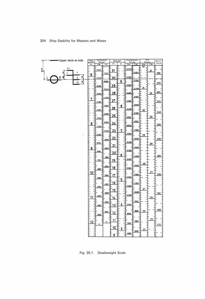
304 Ship Stability for Masters and Mates
Fig. 35.1. Deadweight Scale

Chapter 36
Interaction
What exactly is interaction?Interaction occurs when a ship comes too close to another ship or too closeto, say, a river or canal bank. As ships have increased in size (especially inBreadth Moulded), Interaction has become very important to consider. InFebruary 1998, the Marine Safety Agency (MSA) issued a Marine Guidancenote `Dangers of Interaction', alerting Owners, Masters, Pilots, and Tug-Masters on this topic.Interaction can result in one or more of the following characteristics:
1 If two ships are on a passing or overtaking situation in a river the squatsof both vessels could be doubled when their amidships are directly inline.
2 When they are directly in line each ship will develop an angle of heel andthe smaller ship will be drawn bodily towards the larger vessel.
3 Both ships could lose steerage ef®ciency and alter course without changein rudder helm.
4 The smaller ship may suddenly veer off course and head into the adjacentriver bank.
5 The smaller ship could veer into the side of the larger ship or worse stillbe drawn across the bows of the larger vessel, bowled over and capsized.
In other words there is:
(a) a ship to ground interaction;(b) a ship to ship interaction;(c) a ship to shore interaction.
What causes these effects of interaction? The answer lies in the pressurebulbs that exist around the hull form of a moving ship model or a movingship. See Figure 36.1. As soon as a vessel moves from rest, hydrodynamicsproduce the shown positive and negative pressure bulbs. For ships withgreater parallel body such as tankers these negative bulbs will be
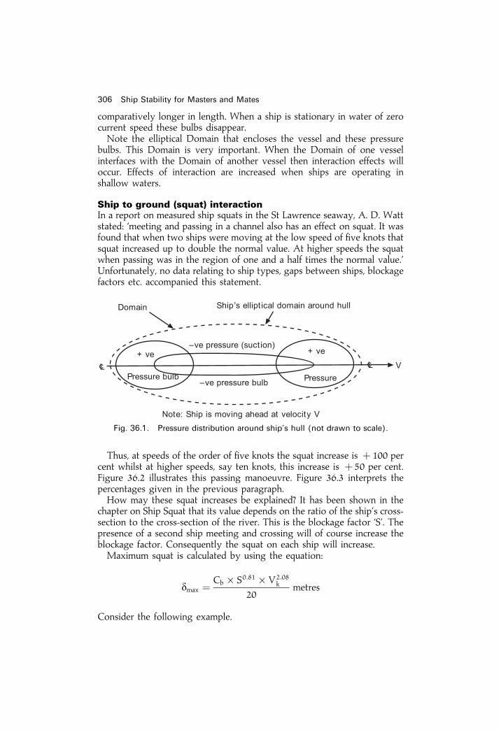
comparatively longer in length. When a ship is stationary in water of zerocurrent speed these bulbs disappear.Note the elliptical Domain that encloses the vessel and these pressure
bulbs. This Domain is very important. When the Domain of one vesselinterfaces with the Domain of another vessel then interaction effects willoccur. Effects of interaction are increased when ships are operating inshallow waters.
Ship to ground (squat) interactionIn a report on measured ship squats in the St Lawrence seaway, A. D. Wattstated: `meeting and passing in a channel also has an effect on squat. It wasfound that when two ships were moving at the low speed of ®ve knots thatsquat increased up to double the normal value. At higher speeds the squatwhen passing was in the region of one and a half times the normal value.'Unfortunately, no data relating to ship types, gaps between ships, blockagefactors etc. accompanied this statement.
Thus, at speeds of the order of ®ve knots the squat increase is � 100 percent whilst at higher speeds, say ten knots, this increase is � 50 per cent.Figure 36.2 illustrates this passing manoeuvre. Figure 36.3 interprets thepercentages given in the previous paragraph.How may these squat increases be explained? It has been shown in the
chapter on Ship Squat that its value depends on the ratio of the ship's cross-section to the cross-section of the river. This is the blockage factor `S'. Thepresence of a second ship meeting and crossing will of course increase theblockage factor. Consequently the squat on each ship will increase.Maximum squat is calculated by using the equation:
dmax � Cb � S0:81 � V2:08k
20metres
Consider the following example.
306 Ship Stability for Masters and Mates
Fig. 36.1. Pressure distribution around ship's hull (not drawn to scale).

Interaction 307
Fig. 36.2. Amidships (�e�) of VLCC directly in line with amidships of OBO ship in
St Lawrence seaway.
Fig. 36.3. Maximum squats for one ship, and for the same ship with another ship
present.

������� �� ��������� ��� � ���� �� �� �� � ���� � ������ ������� ���� �� ����� ����� �� ������ �� ���� � ����� �� ��� � � �� � ���� ���������� ������������� � ��� ���� �� � �� � ��� !" �� ��#��$ ��������� ��� ��%���� �&������ ��� �� � ��� ����� ��� �� ���� ������
� � �� '
"� (� ��� �����
���� ��� ����)
���% � ��#��� ����)��#� � ����#
��� ���� �
������� ������ �� ���� ���� ��������� ����� � ������ ������� ���� ������������� �� � ��� ��� *����� +��,� � ���� ������� ���� ��� � ���� �� �� +� � �!� �� ���#�$ � � ������ ������� ���� �� ����# � ��������� ��� ��%�����&���� �� ���� ������� ��� ���- ��� ����������- � ��� �� �����
� � ��� � '�� � ��� � '��"� (
� � ���� ������ � �+�� ����#����� ��
� �����
���������.
���% � ��#��� �������#� � ����#
��
� ��+# � �� ��� ���
!������ ����.
���% � ���#�� �������#� � ����#
��
� ���� � �� ��� ����
'�� ��%���� �&��� �� ��+# � ��� ��� ��������� ���� �� �� ��� ��� ���������� !� �� ������� ��� ������ /�%���� �&��� ��� ��� ������� ���� ���� �� ����� ����$ ������� ��� !� �� ���� ��� ������ �� ���� ���� ���� �� ���� ��
� ���� ������� ���� �� �������� ���� � ��� ����� ��� �� ��� ����� ������ ��%���� �&��� �� ��� ���� ���� ���� ��- ��� ���� �� '��� ���������� �� ��� ����� ������ ��� ���� ��� ����� ��� �&����
!�����-$ ����� ������� ���� ���� ��� ������� �� � ���� ���� ��� ����������� �&���� 0����� � ����� ������ ���� ���� ��� ������� ������ � �&����������� '���� ������ ��� �� &���������� ��� ��- ������������ �� ���� �������� �� ��������� � � ���� �� ���� 1�&���2 ��������� 3�����������$ ���- ������������� �� �� 4� 5���6� ���������
���� �� ���� ���� ���!��� �� *����� +��� ����� � ��� �� �������� � ����� ���� � � ����������� '���� ����� ���� ��� ���� ��� .
��� ���� ������� �� ������ �� ����
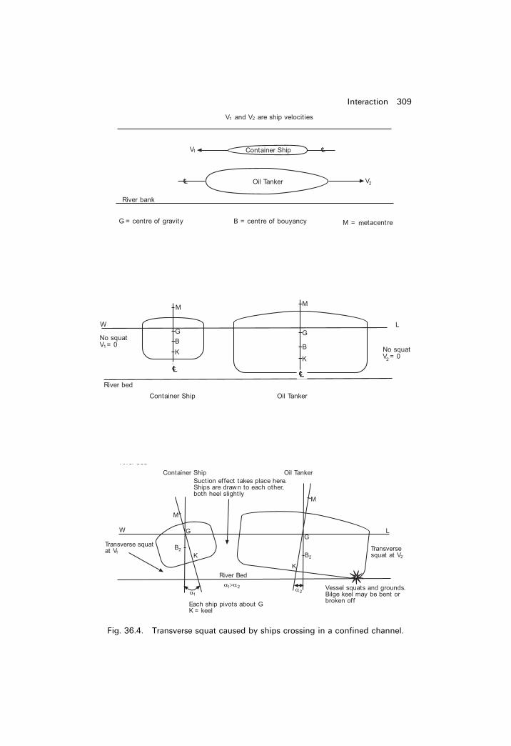
Interaction 309
Fig. 36.4. Transverse squat caused by ships crossing in a con®ned channel.
LcLc

Fig. 36.5. Ship to ship interaction in a narrow river during an overtaking manoeuvre.

Case 1. The tug has just come up to aft port quarter of the ship. TheDomains have become in contact. Interaction occurs. The positive bulb ofthe ship reacts with the positive bulb of the tug. Both vessels veer to portside. Rate of turn is greater on the tug. There is a possibility of the tugveering off into the adjacent river bank as shown in Figure 36.5.
Case 2. The tug is in danger of being drawn bodily towards the shipbecause the negative pressure (suction) bulbs have interfaced. The biggerthe differences between the two deadweights of these ships the greater willbe this transverse attraction. Each ship develops an angle of heel as shown.There is a danger of the ship losing a bilge keel or indeed fracture of thebilge strakes occurring. This is `transverse squat', the loss of underkeelclearance at forward speed. Figure 36.4 shows this happening with thetanker and the container ship.
Case 3. The tug is positioned at the ship's forward port quarter. TheDomains have become in contact via the positive pressure bulbs. Bothvessels veer to the starboard side. Rate of turn is greater on the tug. Thereis great danger of the tug being drawn across the path of the ship's headingand bowled over. This has actually occurred with resulting loss of life.
Note how in these three cases that it is the smaller vessel, be it a tug, apleasure craft or a local ferry involved, that ends up being the casualty!!Figures 36.6 and 36.7 give further examples of ship to ship Interaction
effects in a river.
Methods for reducing the effects of Interaction in Cases 1 to 5Reduce speed of both ships and then if safe increase speeds after themeeting crossing manoeuvre time slot has passed. Resist the temptation togo for the order `increase revs' This is because the forces involved withInteraction vary as the speed squared. However, too much a reduction inspeed produces a loss of steerage because rudder effectiveness is decreased.This is even more so in shallow waters, where the propeller rpm decreasefor similar input of deep water power. Care and vigilance are required.Keep the distance between the vessels as large as practicable bearing in
mind the remaining gaps between each ship side and nearby river bank.Keep the vessels from entering another ship's Domain, for example
crossing in wider parts of the river.Cross in deeper parts of the river rather than in shallow waters, bearing in
mind those increases in squat.Make use of rudder helm. In Case 1, starboard rudder helm could be
requested to counteract loss of steerage. In Case 3, port rudder helm wouldconteract loss of steerage.
Ship to shore interactionFigures 36.8 and 36.9 show the ship to shore Interaction effects. Figure 36.8shows the forward positive pressure bulb being used as a pivot to bring aship alongside a river bank.
Interaction 311
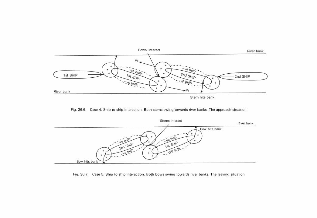
Fig. 36.6. Case 4. Ship to ship interaction. Both sterns swing towards river banks. The approach situation.
Fig. 36.7. Case 5. Ship to ship interaction. Both bows swing towards river banks. The leaving situation.

Figure 36.9 shows how the positive and negative pressure bulbs havecaused the ship to come alongside and then to veer away from the jetty.Interaction could in this case cause the stern to swing and collide with thewall of this jetty.
SummaryAn understanding of the phenomenon of Interaction can avert a possiblemarine accident. Generally a reduction in speed is the best preventiveprocedure. This could prevent on incident leading to loss of sea worthiness,loss of income for the shipowner, cost of repairs, compensation claims andmaybe loss of life.
Interaction 313
Fig. 36.8. Ship to bank interaction. Ship approaches slowly and pivots on for-
ward positive pressure bulb.
Fig. 36.9. Ship to bank interaction. Ship comes in at too fast a speed. Interaction
causes stern to swing towards river bank and then hits it.

314 Ship Stability for Masters and Mates
Exercise 36
1 A river is 150m wide and has 12m depth of water. A passenger linerhaving a breadth of 30m a static even-keel draft of 10m and a Cb of 0.625is proceeding along this river at 8 kts. She meets an approaching generalcargo vessel having a breadth of 20m, a static even-keel draft of 8m and aCb of 0.700 moving at 7 kts.
Estimate the maximum squats of each vessel when their amidships aretransversely in line.
2 With the aid of sketches, de®ne Interaction and list how its effects may belimited. Show clearly how Interaction and transverse squat are inter-related.

Chapter 37
Effect of change ofdensity on draftand trimWhen a ship passes from water of one density to water of another densitythe mean draft is changed and if the ship is heavily trimmed, the change inthe position of the centre of buoyancy will cause the trim to change.
Let the ship in Figure 37.1 ¯oat in salt water at the waterline WL. Brepresents the position of the centre of buoyancy and G the centre ofgravity. For equilibrium, B and G must lie in the same vertical line.If the ship now passes into fresh water, the mean draft will increase. Let
W1L1 represent the new waterline and b the centre of gravity of the extravolume of the water displaced. The centre of buoyancy of the ship, beingthe centre of gravity of the displaced water, will move from B to B1 in adirection directly towards b. The force of buoyancy now acts verticallyupwards through B1 and the ship's weight acts vertically downwardsthrough G, giving a trimming moment equal to the product of thedisplacement and the longitudinal distance between the centres of gravityand buoyancy. The ship will then change trim to bring the centres ofgravity and buoyancy back in to the same vertical line.
ExampleA box-shaped pontoon is 36m long, 4 m wide and ¯oats in salt water at draftsF 2.00m. A 4.00m. Find the new drafts if the pontoon now passes into fresh
Fig. 37.1

water. Assume salt water density is 1.025 t/m3. Assume fresh waterdensity� 1.000 t/m3.
(a) To Find the Position of B1
BB1 � v� gg1V
v � 1
2� 1� 36
2� 4
� 36 cu. m
gg1 �2
3� 36
gg1 � 24 m
V � 36� 4� 3
� 432 cu. m
; BB1 � 36� 24
432
� 2m
Because the angle of trim is small, BB1 is considered to be the horizontalcomponent of the shift of the centre of buoyancy.Now let the pontoon enter fresh water, i.e. from rSW into rFW. Pontoon will
develop mean bodily sinkage.
(b) To Find the New DraftIn Salt Water
Mass � Volume� Density
� 36� 4� 3� 1:025In Fresh Water.
Mass � Volume� Density
; Volume � Mass
Density
� 36� 4� 3� 1:025
1:000cu. m
(Mass in Salt water � Mass in Fresh Water)
316 Ship Stability for Masters and Mates
Fig. 37.2
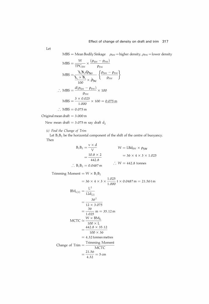
Let
MBS � Mean Bodily Sinkage �SW�higher density; �FW� lower density
MBS � W
TPCSW� �rSW ÿ rFW�
rFW
MBS � LCBCdrSWLC � BC100
� rSW
rSW ÿ rFWrFW
� �
; MBS � d�rSW ÿ rFW�rFW
� 100
MBS � 3� 0:025
1:000� 100 � 0:075m
; MBS � 0:075m
Original mean draft � 3:000m
New mean draft � 3:075m say draft d2
(c) Find the Change of TrimLet B1B2 be the horizontal component of the shift of the centre of buoyancy.
Then
B1B2 � v� d
V
� 10:8� 2
442:8
; B1B2 � 0:0487m
W � LBdSW � rSW� 36� 4� 3� 1:025
; W � 442:8 tonnes
Trimming Moment � W� B1B2
� 36� 4� 3� 1:025
1:000t� 0:0487m � 21:56 t m
BML�2� � L2
12d�2�
� 362
12� 3:075
� 36
1:025m � 35:12m
MCTC ' W� BML
100� L
� 442:8� 35:12
100� 36� 4:32 tonnes metres
Change of Trim � Trimming Moment
MCTC
� 21:56
4:32� 5 cm
Effect of change of density on draft and trim 317
Change of Trim � 5 cm by the stern
� 0:05m by the stern
Drafts before Trimming A 4.075m F 2.075m
Change due to trim �0:025m ÿ0:025mNew Drafts A 4.100m F 2.050m
In practice the trimming effects are so small that they are often ignored byshipboard personnel. Note in the above example the trim ratio forward and aftwas only 2 1
2 cm.However, for D.Tp. examinations, they must be studied and fully under-
stood.
318 Ship Stability for Masters and Mates
Exercise 37
1 A box-shaped vessel is 72m long, 8 m wide and ¯oats in salt water at draftsF 4.00m. A 8.00m. Find the new drafts if the vessel now passes into freshwater.
2 A box-shaped vessel is 36m long, 5 m wide and ¯oats in fresh water atdrafts F 2.50m. A 4.50m. Find the new drafts if the vessel now passes intosalt water.
3 A ship has a displacement of 9100 tonnes, LBP of 120m, even-keel draft of7 m in fresh water of density of 1.000 t/m3.
From her Hydrostatic Curves it was found that:
MCTCSW is 130 t m/cmTPCSW is 17.3 tLCB is 2m forward �e� andLCF is 1.0 aft �e�:
Calculate the new end drafts when this vessel moves into water having adensity of 1.02 t/m3 without any change in the ship's displacement of 9100tonnes.

Chapter 38
List with zerometacentric heightWhen a weight is shifted transversely in a ship with zero initial metacentricheight, the resulting list can be found using the `Wall sided' formula.
The ship shown in Figure 38.1 has zero initial metacentric height. When aweight of mass `w' is shifted transversely through a distance `d', the ship'scentre of gravity shifts from G to G1 where the direction GG1 is parallel tothe shift of the centre of gravity of the weight shifted. The ship will thenincline to bring the centres of gravity and buoyancy in the same verticalline.The horizontal component of the shift of the ship's centre of gravity is
equal to GZ and the horizontal component of the shift of the centre of
Fig. 38.1

������� � �� ����� � ����� �� � �� ��
� �� ���� � � �� ��
�� ����� ��� ������ ��� � ������� ����� �� �� �� � ��� �� ����� ��� �� ������ ����� �����������
�� � ���� ! �"�����! �� �� �
� �� ���� � � �� �� � ���� ! �"�����! ��
#�� � $
����� ���� � � �� �� ��
! "�����! �
�� �
�� �� �
�� �� ! �"�����! �
!����"���
� ���% �
��
��� � ���������������!����"���
%
�
�������& �' � ! !($ ����� �� '��������� � )�� *�� )"� %�*�� )�� *���� � +������ �'����� ,��� �� �� � � � ����� � ! ����� � ������� �� ������ � ���� ���� ��� ��� ����� � ���-����� �� ����� � !�� � ����� ��� �� �' � ����� �����
)� � *�$�
�)" � %�*�
"� � .�!�
�� �' � -��� ��
� ��� �� � ���������������!������"�
%
�
��� �� � ��������������������������
!�!� ! ! !($� .�!
%
�� $�$/00
���� 1� � � (� %.�
��� ���� ������� �� ������ �� ����

List with zero metacentric height 321
Exercise 38
1 Find the list when a mass of 10 tonnes is shifted transversely through ahorizontal distance of 14m in a ship of 8000 tonnes displacement whichhas zero initial metacentric height. BM� 2m.
2 A ship of 8000 tonnes displacement has zero initial metacentric height.BM� 4m. Find the list if a weight of 20 tonnes is shifted transverselyacross the deck through a horizontal distance of 10m.
3 A ship of 10 000 tonnes displacement is ¯oating in water of density1.025 kg/cu. m and has a zero initial metacentric height. Calculate the listwhen a mass of 15 tonnes is moved transversely across the deck through ahorizontal distance of 18m. The second moment of the waterplane areaabout the centre line is 105 m4:
4 A ship of 12 250 tonnes displacement is ¯oating upright. KB� 3.8 m,KM� 8m and KG� 8m. Assuming that the ship is wall-sided, ®nd the listif a mass of 2 tonnes, already on board, is shifted transversely through ahorizontal distance of 12m.

Chapter 39
The Trim and StabilitybookWhen a new ship is nearing completion, a Trim and Stability book isproduced by the shipbuilder and presented to the shipowner. Shipboardof®cers will use this for the day to day operation of the vessel. In the Trimand Stability book is the following technical data:
1 General particulars of the ship.2 Inclining experiment report and its results.3 Capacity, VCG, LCG particulars for all holds, compartments, tanks etc.4 Cross curves of stability. These may be GZ curves or KN curves.5 Deadweight scale data. May be in diagram form or in tabular form.6 Hydrostatic curves. May be in graphical form or in tabular form.7 Example conditions of loading such as:
Lightweight (empty vessel) condition.Full-loaded Departure and Arrival conditions.Heavy-ballast Departure and Arrival conditions.Medium-ballast Departure and Arrival conditions.Light-ballast Departure and Arrival conditions.
On each condition of loading there is a pro®le and plan view (at upperdeck level usually). A colour scheme is adopted for each item ofdeadweight. Examples could be red for cargo, blue for fresh water,green for water ballast, brown for oil. Hatched lines for this Dwtdistribution signify wing tanks P and S.For each loaded condition, in the interests of safety, it is necessary to
show:
Deadweight.End draughts, thereby signifying a satisfactory and safe trim situation.KG with no Free Surface Effects (FSE), and KG with FSE taken intoaccount.

Final transverse metacentric height (GM). This informs the of®cer if theship is in stable, unstable or neutral equilibrium. It can also indicate ifthe ship's stability is approaching a dangerous state.
Total Free Surface Effects of all slack tanks in this condition ofloading.
A statical stability curve relevant to the actual loaded condition with theimportant characteristics clearly indicated. For each S/S curve it isimportant to observe the following:
Maximum GZ and the angle of heel at which it occurs.Range of stability.Area enclosed from zero degrees to thirty degrees (A1) and the areaenclosed from thirty degrees to forty degrees (A2) as shown in Figure39.1.
Shear force and bending moment curves, with upper limit lines clearlysuperimposed as shown in Figure 39.2.
8 Metric equivalents. For example, TPI 00 to TPC, MCTI00 to MCTC, ortons to tonnes.
All of this information is sent to a D.Tp. surveyor for appraisal. On manyships today this data is part of a computer package. The deadweight itemsare keyed in by the of®cer prior to any weights actually being moved. Thecomputer screen will then indicate if the prescribed condition of loading isindeed safe from the point of view of stability and strength.
The Trim and Stability book 323
Fig. 39.1. Enclosed areas on a statical stability curve.

324 Ship Stability for Masters and Mates
Fig. 39.2. SF and BM curves with upper limit lines.
Chapter 40
Bending of beams
Beam theoryThe bending of ships can be likened to the bending of beams in many cases.This chapter shows the procedures employed with beam theory.The problem of calculating the necessary strength of ships is made
dif®cult by the many and varied forces to which the ship structure issubjected during its lifetime. These forces may be divided into two groups,namely statical forces and dynamical forces.The statical forces are due to:
1 The weight of the structure which varies throughout the length of theship.
2 Buoyancy forces, which vary over each unit length of the ship and areconstantly varying in a seaway.
3 Direct hydrostatic pressure.4 Concentrated local weights such as machinery, masts, derricks, winches,etc.
The dynamical forces are due to:
1 Pitching, heaving and rolling,2 Wind and waves.
These forces cause bending in several planes and local strains are set updue to concentrated loads. The effects are aggravated by structuraldiscontinuities.The purpose of the present chapter is to consider the cause of longi-
tudinal bending and its effect upon structures.
StressesA stress is the mutual actual between the parts of a material to preservetheir relative positions when external loads are applied to the material.

Thus, whenever external loads are applied to a material stresses are createdwithin the material.
Tensile and compressive stressesWhen an external load is applied to a material in such a way as to cause anextension of the material it is called a `tensile' load, whilst an external loadtending to cause compression of the material is a `compressive' load.Figure 40.1 shows a piece of solid material of cylindrical section to which
an external load W is applied. In the ®rst case the load tends to cause anextension of the material and is therefore a tensile load. The applied loadcreates stresses within the material and these stresses are called `tensile'stresses. In the second case the load applied is one of compression and theconsequent stresses within the material are called `compressive' stresses.When a tensile or compressive external load is applied to a material the
material will remain in equilibrium only so long as the internal forces canresist the stresses created.
Shearing stressesA shearing stress is a stress within a material which tends to break or shearthe material across.Figure 40.2(a) and 40.2(b) illustrate shearing stresses which act normally
to the axis of the material.In the following text when the direction of a shearing stress is such that
326 Ship Stability for Masters and Mates
Fig. 40.1

the section on the right-hand side of the material tends to move down-wards, as shown in Figure 40.2(a), the stress is considered to be positive,and when the direction of a stress is such that the section on the right-handside tends to move upwards as shown in Figure 40.2(b), the shearing stressis considered to be negative.
Bending of beams 327
Fig. 40.2

Shearing stresses are resisted by the material but shearing will take placewhen the shear stress reaches the ultimate shear stress of the material.
Complementary stressIt has already been stated that when a direct load is applied to a materialstresses are created within the material and that the material will remain inequilibrium only so long as the internal forces can resist the stresses created.Let the bar in Figure 40.3(a) be subjected to tensile load W and imagine
the bar to be divided into two parts at section AB.For equilibrium, the force W on the left-hand side of the bar is balanced
by an equal force acting to the right at section AB. The balancing force issupplied by the individual molecular forces which represent the action ofthe molecules on the right-hand side of the section on those of the left-handsection. Similarly, the force W on the right-hand side of the bar is balancedby the individual molecular forces to the left of the section. Therefore, whenan external load W is applied to the bar, at any section normal to the axis ofthe bar, there are equal and opposite internal forces acting, each of whichbalances the external force W. The magnitude of the internal forces per unitarea of cross-section is called the stress. When the section is well removedfrom the point of application of the external load then the stress may beconsidered constant at all parts of the section and may be found by theformula:
Stress (f) � Load (W)
Area (A); f � W
A
Let us now consider the stresses created by the external load W in asection which is inclined to the axis of the bar. For example, let section CDin Figure 40.3(b) be inclined at an angle y to the normal to the axis of thebar and let the section be suf®ciently removed from the point of applicationof the load to give uniform stress across the section.The load transmitted by the section CD, for equilibrium, is equal to the
external force W. This load can be resolved into two components, one ofwhich is WEcos y and acts normal to the section, and the other is WEsin yand acts tangential to the section. This shows that for direct tensile orcompressive loading of the bar stresses other than normal stresses may becreated.Now let us consider the small block of material abcd in the section on the
left-hand side of the plane, as shown in Figure 40.3(c). Let the face ab becoincident with the plane CD and let FN be the internal force normal to thisface and FT the internal force tangential to the face. For the block to be inequilibrium the left-hand side of the section must provide two stresses onthe face cd. These are FN and FT. Thus the stress FN normal to the face ab isbalanced by the stress FN normal to the face cd whilst the two tangentialstresses (FT) on these faces tend to produce clockwise rotation in the block.Rotation can only be prevented if an equal and opposite couple is produced
328 Ship Stability for Masters and Mates

Bending of beams 329
Fig. 40.3
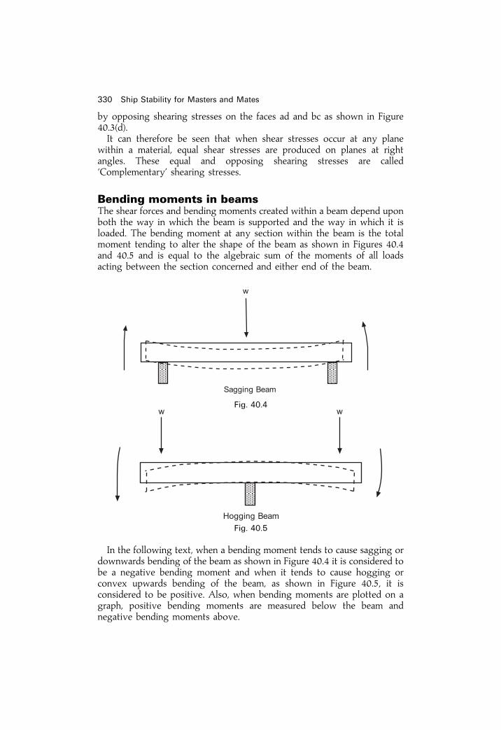
by opposing shearing stresses on the faces ad and bc as shown in Figure40.3(d).It can therefore be seen that when shear stresses occur at any plane
within a material, equal shear stresses are produced on planes at rightangles. These equal and opposing shearing stresses are called`Complementary' shearing stresses.
Bending moments in beamsThe shear forces and bending moments created within a beam depend uponboth the way in which the beam is supported and the way in which it isloaded. The bending moment at any section within the beam is the totalmoment tending to alter the shape of the beam as shown in Figures 40.4and 40.5 and is equal to the algebraic sum of the moments of all loadsacting between the section concerned and either end of the beam.
In the following text, when a bending moment tends to cause sagging ordownwards bending of the beam as shown in Figure 40.4 it is considered tobe a negative bending moment and when it tends to cause hogging orconvex upwards bending of the beam, as shown in Figure 40.5, it isconsidered to be positive. Also, when bending moments are plotted on agraph, positive bending moments are measured below the beam andnegative bending moments above.
330 Ship Stability for Masters and Mates
Fig. 40.4
Fig. 40.5

Shear Force and Bending Moment DiagramsThe shear forces and bending moments created in a beam which issupported and loaded in a particular way can be illustrated graphically.Consider ®rst the case of cantilevers which are supported at one end
only.
Case IThe beam AB in Figure 40.6 is ®xed at one end only and carries a weight`W' at the other end.
If the weight of the beam is ignored then at any point Y in the beam, whichis at distance X from the end B, there is a positive shearing force W and apositive bending moment W� X. There is thus a positive shearing force Wat all sections throughout the length of the beam. This is shown graphicallyin Figure 40.7 where AB represents the length of the beam (l), and theordinate AC, which represents the shearing force at A, is equal to theordinate BD which represents the shearing force at B.The bending moment at any section of the beam is the algebraic sum of
the moments of forces acting on either side of the section. In the presentcase, the only force to consider is W which acts downwards through theend B. Thus the bending moment at B is zero and from B towards A thebending moment increases, varying directly as the distance from the end B.The maximum bending moment, which occurs at A, is equal to W� l. Thisis shown graphically in Figure 40.7 by the straight line BGE.The shearing force and bending moment at any point in the length of the
beam can be found from the graph by inspection. For example, at Y theshearing force is represented by the ordinate YF and the bending momentby the ordinate YG.It should be noted that the bending moment at any point in the beam is
equal to the area under the shearing force diagram from the end of thebeam to that point. For example, in Figure 40.7, the bending moment at Y is
Bending of beams 331
Fig. 40.6

equal to W� X and this, in turn, is equal to the area under the shearingforce diagram between the ordinates BD and YF.
Case IINow consider a solid beam of constant cross-section which is supported atone end as shown in Figure 40.8. Let w be the weight per unit length of thebeam.At any section Y in the beam, which is at distance `X' from B, there is a
positive shearing force wX where wX is the weight of the beam up to thatsection and, since the weight wX may be taken to act half-way along the
length X, there is a bending moment wX� X/2 orwX2
2.
This is shown graphically in Figure 40.9, where AB represents the lengthof the beam (l).
332 Ship Stability for Masters and Mates
W� l
Fig. 40.7
Fig. 40.8
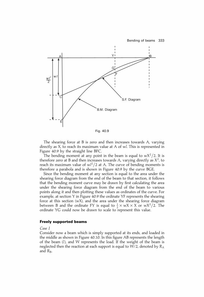
The shearing force at B is zero and then increases towards A, varyingdirectly as X, to reach its maximum value at A of wl. This is represented inFigure 40.9 by the straight line BFC.The bending moment at any point in the beam is equal to wX2=2. It is
therefore zero at B and then increases towards A, varying directly as X2, toreach its maximum value of wl2=2 at A. The curve of bending moments istherefore a parabola and is shown in Figure 40.9 by the curve BGE.Since the bending moment at any section is equal to the area under the
shearing force diagram from the end of the beam to that section, it followsthat the bending moment curve may be drawn by ®rst calculating the areaunder the shearing force diagram from the end of the beam to variouspoints along it and then plotting these values as ordinates of the curve. Forexample, at section Y in Figure 40.9 the ordinate YF represents the shearingforce at this section (wX), and the area under the shearing force diagrambetween B and the ordinate FY is equal to 1
2� wX� X or wX2=2. Theordinate YG could now be drawn to scale to represent this value.
Freely supported beams
Case IConsider now a beam which is simply supported at its ends, and loaded inthe middle as shown in Figure 40.10. In this ®gure AB represents the lengthof the beam (l ), and W represents the load. If the weight of the beam isneglected then the reaction at each support is equal to W/2, denoted by RA
and RB.
Bending of beams 333
Fig. 40.9
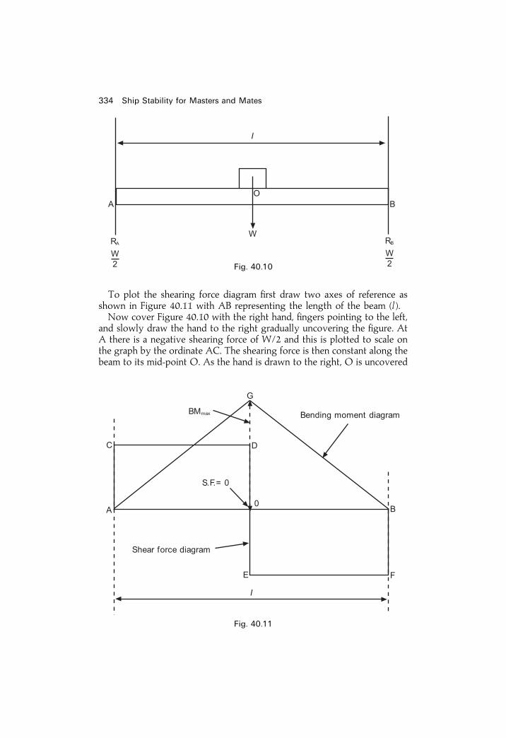
To plot the shearing force diagram ®rst draw two axes of reference asshown in Figure 40.11 with AB representing the length of the beam (l ).Now cover Figure 40.10 with the right hand, ®ngers pointing to the left,
and slowly draw the hand to the right gradually uncovering the ®gure. AtA there is a negative shearing force of W/2 and this is plotted to scale onthe graph by the ordinate AC. The shearing force is then constant along thebeam to its mid-point O. As the hand is drawn to the right, O is uncovered
334 Ship Stability for Masters and Mates
Fig. 40.10
Fig. 40.11

and a force W downwards appears. This must be considered in addition tothe force W/2 upwards at A. The resultant is a shearing force of W/2downwards and this force is then constant from O to B as shown in Figure40.11 by the straight line EF.The bending moment diagram can now be drawn in the same way or by
®rst calculating the area under the shearing force diagram between theordinate AC and various points along the beam and then plotting thesevalues as ordinates on the bending moment diagram. It will be seen that thebending moment is zero at the ends and attains its maximum value at themid-point in the beam indicated by the ordinate OG. Note BMmax occurswhen SF� 0.
Case IINow consider a beam of constant cross-sectional area, of length l, andweight w per unit length. Let the beam be simply supported at its ends asshown in Figure 40.12, at reactions RA and RB.The total weight of the beam is wl. The reaction at each end is equal to
wl=2, half of the weight of the beam.The shearing force and bending moment diagrams can now be drawn as
in the previous example. In Figure 40.12, let AB represent the length of thebeam (l) drawn to scale. At A the shearing force is wl=2 upwards and this isshown on the graph by the ordinate AC. Because the weight of the beam isevenly distributed throughout its length, the shearing force decreasesuniformly from A towards B.At the mid-point (O) of the beam there is a shearing force of wl=2
downwards (half the weight of the beam) and one of wl=2 upwards (thereaction at A) to consider. The resultant shearing force at O is thereforezero. Finally, at B, there is a shearing force of wl downwards (the weight ofthe beam) and wl=2 upwards (the reaction at A) to consider, giving aresultant shearing force of wl=2 downwards which is represented on thegraph by the ordinate BD.
Bending of beams 335
Fig. 40.12
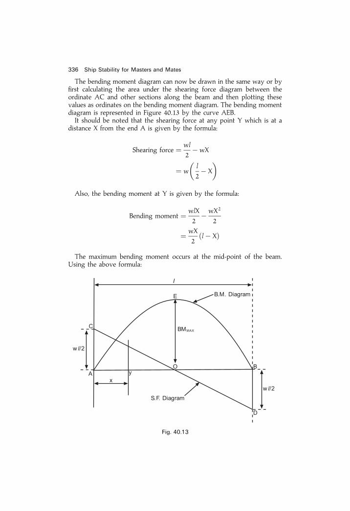
The bending moment diagram can now be drawn in the same way or by®rst calculating the area under the shearing force diagram between theordinate AC and other sections along the beam and then plotting thesevalues as ordinates on the bending moment diagram. The bending momentdiagram is represented in Figure 40.13 by the curve AEB.It should be noted that the shearing force at any point Y which is at a
distance X from the end A is given by the formula:
Shearing force � wl
2ÿ wX
� w
�l
2ÿ X
�Also, the bending moment at Y is given by the formula:
Bending moment � wlX
2ÿ wX2
2
� wX
2�lÿ X�
The maximum bending moment occurs at the mid-point of the beam.Using the above formula:
336 Ship Stability for Masters and Mates
Fig. 40.13
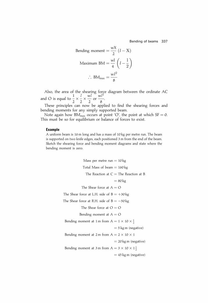
Bending moment � wX
2�l ÿX�
Maximum BM � wl
4
�l ÿ l
2
�; BMmax � wl 2
8
Also, the area of the shearing force diagram between the ordinate AC
and O is equal to1
2� l
2� wl
2or
wl2
8.
These principles can now be applied to ®nd the shearing forces andbending moments for any simply supported beam.Note again how BMmax occurs at point `O', the point at which SF� 0.
This must be so for equilibrium or balance of forces to exist.
ExampleA uniform beam is 16m long and has a mass of 10 kg per metre run. The beamis supported on two knife edges, each positioned 3m from the end of the beam.Sketch the shearing force and bending moment diagrams and state where thebending moment is zero.
Mass per metre run � 10 kg
Total Mass of beam � 160 kg
The Reaction at C � The Reaction at B
� 80 kg
The Shear force at A � O
The Shear force at L.H. side of B � �30 kgThe Shear force at R.H. side of B � ÿ50 kg
The Shear force at O � O
Bending moment at A � O
Bending moment at 1m from A � 1� 10� 12
� 5 kgm (negative)
Bending moment at 2m from A � 2� 10� 1
� 20 kgm (negative)
Bending moment at 3m from A � 3� 10� 1 12
� 45 kgm (negative)
Bending of beams 337

Bending moment at 4m from A � 4� 10� 2ÿ 80� 1
� 0
Bending moment at 5m from A � 5� 10� 52ÿ 80� 2
� 35 kgm (positive)
Bending moment at 6m from A � 6� 10� 3ÿ 80� 3
� 60 kgm (positive)
Bending moment at 7m from A � 7� 10� 72ÿ 80� 4
� 75 kgm (positive)
Bending moment at 8m from A � 8� 10� 4ÿ 80� 5
� 80 kgm (positive)
Ans. Bending moment � 0 at 4m from each end, and at each end of the beam
The results of the above investigation into the shearing forces andconsequent bending moments in simply supported beams will now be
338 Ship Stability for Masters and Mates
Fig. 40.14

applied to ®nd the longitudinal shearing forces and bending moments in¯oating vessels. Suf®cient accuracy of prediction can be obtained.However, beam theory such as this cannot be used for supertankers and
ULCCs. For these very large vessels it is better to use what is known as the®nite element theory. This is beyond the remit of this book.
Bending of beams 339
EXERCISE 40
1 A beam AB of length 10m is supported at each end and carries a load whichincreases uniformly from zero at A to 0.75 tonnes per metre run at B. Findthe position and magnitude of the maximum bending moment.
2 A beam 15m long is supported at its ends and carries two point loads. Oneof 5 tonnes mass is situated 6m from one end and the other of 7 tonnes massis 4 m from the other end. If the mass of the beam is neglected, sketch thecurves of shearing force and bending moments. Also ®nd (a), The maximumbending moment and where it occurs, and (b), The bending moment andshearing force at 1
3 of the length of the beam from each end.

Chapter 41
Bending of ships
Longitudinal stresses in still waterFirst consider the case of a homogeneous log of rectangular section ¯oatingfreely at rest in still water as shown in Figure 41.1.
The total weight of the log is balanced by the total force of buoyancyand the weight (W) of any section of the log is balanced by the force ofbuoyancy (B) provided by that section. There is therefore no bendingmoment longitudinally which would cause stresses to be set up in the log.Now consider the case of a ship ¯oating at rest in still water, on an even
keel, at the light draft as shown in Figure 41.2Although the total weight of the ship is balanced by the total force of
buoyancy, neither is uniformly distributed throughout the ship's length.Imagine the ship to be cut as shown by a number of transverse sections.Imagine, too, that each section is watertight and is free to move in a verticaldirection until it displaces its own weight of water. The weight of each ofthe end sections (1 and 5) exceeds the buoyancy which they provide andthese sections will therefore sink deeper into the water until equilibrium isreached at which time each will be displacing its own weight of water. If
Fig. 41.1

sections 2 and 4 represent the hold sections, these are empty and theytherefore provide an excess of buoyancy over weight and will rise todisplace their own weight of water. If section 3 represents the engine roomthen, although a considerable amount of buoyancy is provided by thesection, the weight of the engines and other apparatus in the engine room,may exceed the buoyancy and this section will sink deeper into the water.The nett result would be as shown in Figure 41.3 where each of the sectionsis displacing its own weight of water.
Although the sections in the ship are not free to move in this way,bending moments, and consequently longitudinal stresses, are created bythe variation in the longitudinal distribution of weight and buoyancy andthese must be allowed for in the construction of the ship.
Longitudinal stresses in wavesWhen a ship encounters waves at sea the stresses created differ greatlyfrom those created in still water. The maximum stresses are considered toexist when the wave length is equal to the ship's length and either a wavecrest or trough is situated amidships.Consider ®rst the effect when the ship is supported by a wave having its
crest amidships and its troughs at the bow and the stern, as shown in Figure41.4.
Bending of ships 341
Fig. 41.2
Fig. 41.3
Fig. 41.4

In this case, although once more the total weight of the ship is balancedby the total buoyancy, there is an excess of buoyancy over the weightamidships and an excess of weight over buoyancy at the bow and the stern.This situation creates a tendency for the ends of the ship to movedownwards and the section amidships to move upwards as shown inFigure 41.5.
Under these conditions the ship is said to be subjected to a `Hogging'stress.A similar stress can be produced in a beam by simply supporting it at its
mid-point and loading each end as shown in Figure 41.6.
Consider the effect after the wave crest has moved onwards and the shipis now supported by wave crests at the bow and the stern and a troughamidships as shown in Figure 41.7.There is now an excess of buoyancy over weight at the ends and an
excess of weight over buoyancy amidships. The situation creates atendency for the bow and the stern to move upwards and the sectionamidships to move downwards as shown in Figure 41.8.Under these conditions a ship is said to be subjected to a sagging stress.
A stress similar to this can be produced in a beam when it is simplysupported at its ends and is loaded at the mid-length as shown in Figure41.9.
342 Ship Stability for Masters and Mates
Fig. 41.5
Fig. 41.6

Weight, buoyancy and load diagramsIt has already been shown that the total weight of a ship is balanced by thetotal buoyancy and that neither the weight nor the buoyancy is evenlydistributed throughout the length of the ship.In still water, the uneven loading which occurs throughout the length of
a ship varies considerably with different conditions of loading and leads tolongitudinal bending moments which may reach very high values. Care istherefore necessary when loading or ballasting a ship to keep these valueswithin acceptable limits.In waves, additional bending moments are created, these being brought
about by the uneven distribution of buoyancy. The maximum bendingmoment due to this cause is considered to be created when the ship is
Bending of ships 343
Fig. 41.7
Fig. 41.8
Fig. 41.9
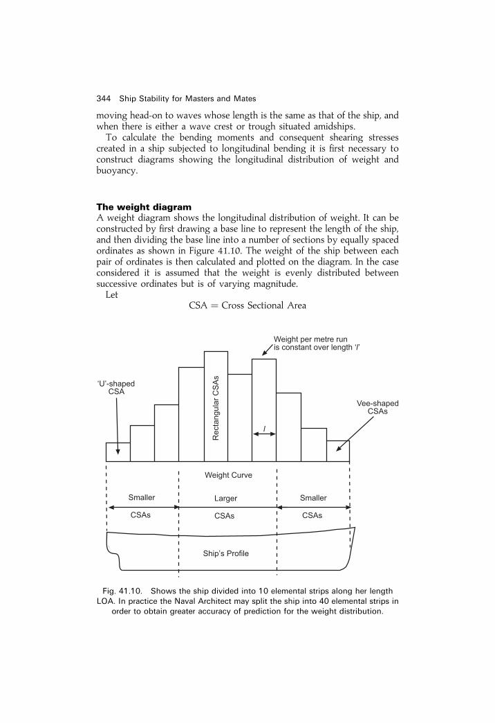
moving head-on to waves whose length is the same as that of the ship, andwhen there is either a wave crest or trough situated amidships.To calculate the bending moments and consequent shearing stresses
created in a ship subjected to longitudinal bending it is ®rst necessary toconstruct diagrams showing the longitudinal distribution of weight andbuoyancy.
The weight diagramA weight diagram shows the longitudinal distribution of weight. It can beconstructed by ®rst drawing a base line to represent the length of the ship,and then dividing the base line into a number of sections by equally spacedordinates as shown in Figure 41.10. The weight of the ship between eachpair of ordinates is then calculated and plotted on the diagram. In the caseconsidered it is assumed that the weight is evenly distributed betweensuccessive ordinates but is of varying magnitude.Let
CSA � Cross Sectional Area
344 Ship Stability for Masters and Mates
Fig. 41.10. Shows the ship divided into 10 elemental strips along her length
LOA. In practice the Naval Architect may split the ship into 40 elemental strips in
order to obtain greater accuracy of prediction for the weight distribution.

Bonjean CurvesBonjean Curves are drawn to give the immersed area of transverse sectionsto any draft and may be used to determine the longitudinal distribution ofbuoyancy. For example, Figure 41.11(a) shows a transverse section of a shipand Figure 41.11(b) shows the Bonjean Curve for the same section. Theimmersed area to the waterline WL is represented on the Bonjean Curve byordinate AB, and the immersed area to waterline W1L1 is represented byordinate CD.In Figure 41.12 the Bonjean Curves are shown for each section
throughout the length of the ship. If a wave formation is superimposedon the Bonjean Curves and adjusted until the total buoyancy is equal to thetotal weight of the ship, the immersed transverse area at each section canthen be found by inspection and the buoyancy in tonnes per metre run isequal to the immersed area multiplied by 1.025.
Bending of ships 345
Fig. 41.11
Fig. 41.12

Chapter 42
Strength curvesfor shipsStrength curves consist of ®ve curves that are closely inter-related. Thecurves are:
1 Weight curve ± tonnes/m run or kg/m run.2 Buoyancy curve ± either for hogging or sagging condition ± tonnes/mor kg/m run.
3 Load curve ± tonnes/m run or kg/m run.4 Shear force curve ± tonnes or kg.5 Bending moment curve ± tonnesm or kgm.
Some forms use units of MN/m run, MN and MN.m.
Buoyancy curvesA buoyancy curve shows the longitudinal distribution of buoyancy and canbe constructed for any wave formation using the Bonjean Curves in themanner previously described in Chapter 41. In Figure 42.1 the buoyancy
Fig. 42.1
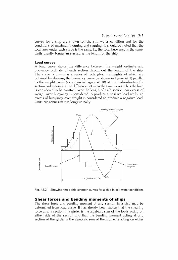
curves for a ship are shown for the still water condition and for theconditions of maximum hogging and sagging. It should be noted that thetotal area under each curve is the same, i.e. the total buoyancy is the same.Units usually tonnes/m run along the length of the ship.
Load curvesA load curve shows the difference between the weight ordinate andbuoyancy ordinate of each section throughout the length of the ship.The curve is drawn as a series of rectangles, the heights of which areobtained by drawing the buoyancy curve (as shown in Figure 42.1) parallelto the weight curve (as shown in Figure 41.10) at the mid-ordinate of asection and measuring the difference between the two curves. Thus the loadis considered to be constant over the length of each section. An excess ofweight over buoyancy is considered to produce a positive load whilst anexcess of buoyancy over weight is considered to produce a negative load.Units are tonnes/m run longitudinally.
Shear forces and bending moments of shipsThe shear force and bending moment at any section in a ship may bedetermined from load curve. It has already been shown that the shearingforce at any section in a girder is the algebraic sum of the loads acting oneither side of the section and that the bending moment acting at anysection of the girder is the algebraic sum of the moments acting on either
Strength curves for ships 347
Fig. 42.2. Showing three ship strength curves for a ship in still water conditions

side of the section. It has also been shown that the shearing force at anysection is equal to the area under the load curve from one end to the sectionconcerned and that the bending moment at that section is equal to the areaunder the shearing force curve measured from the same end to that section.Thus, for the mathematically minded, the shear force curve is the ®rst-
order integral curve of the load curve and the bending moment curve is the®rst-order integral curve of the shearing force curve. Therefore, the bendingmoment curve is the second-order integral curve of the load curve.Figure 42.2 shows typical curves of load, shearing force and bending
moments for a ship in still water.After the still water curves have been drawn for a ship, the changes in the
distribution of the buoyancy to allow for the conditions of hogging andsagging can be determined and so the resultant shearing force and bendingmoment curves may be found for the ship in waves.
ExampleA box-shaped barge of uniform construction is 32m long and displaces 352tonnes when empty, is divided by transverse bulkheads into four equalcompartments. Cargo is loaded into each compartment and level stowed asfollows:
No. 1 hold N 192 tonnes No. 2 hold N 224 tonnes
No. 3 hold N 272 tonnes No. 4 hold N 176 tonnes
Construct load and shearing force diagrams, before calculating the bendingmoments at the bulkheads and at the position of maximum value; hence drawthe bending moment diagram.
Mass of barge per metre run � Mass of barge
Length of barge
� 352
32
� 11 tonnes per metre run
mass of barge when empty � 352 tonnes
Cargo � 192� 224� 272� 176
� 864 tonnes
Total mass of barge and cargo � 352� 864
� 1216 tonnes
Buoyancy per metre run � Total buoyancy
Length of barge
� 1216
32
� 38 tonnes per metre run
348 Ship Stability for Masters and Mates

From Figure 42.3.Bending moments along the barge's length
BM8 � 8� 40
2� 160 t m
� 160 tonnes m
BM0 � 0 t m
BM4 � 20� 4
2� 40 tm
Strength curves for ships 349
Fig. 42.3

BM8 � 8� 40
2� 160 tm
BM13
57� 13 5
7� 40
2� 274:3 t m
BM16 ��13 5
7� 40
2
�ÿ�2 27� 16
2
�� 256 t m
BM20 � 256ÿ�16� 20
2
�E4 � 184 tm
BM24 � 184ÿ�20� 24
2
�E4 � 96 t m
BM28 � 96ÿ�24� 12
2
�E4 � 24 tm
BM32 � 24ÿ�12� 4
2
�� 0 t m
Murray's MethodMurray's Method is used to ®nd the total longitudinal bending momentamidships on a ship in waves and is based on the division of the totalbending moment into two parts:
(a) the Still Water Bending Moment, and(b) the wave bending moment.
The Still Water Bending Moment is the longitudinal bending momentamidships when the ship is ¯oating in still water.When using Murray's Method the wave bending moment amidships is
that produced by the waves when the ship is supported on what is called a`Standard Wave'. A Standard Wave is one whose length is equal to thelength of the ship (L), and whose height is equal to 0.607
���Lp
, where L ismeasured in metres. See Figure 42.4.The Wave Bending Moment is then found using the formula:
WBM � bEBEL2:5 � 10ÿ3 tonnes metres
where B is the beam of the ship in metres and b is a constant based on theship's block coef®cient (Cb) and on whether the ship is hogging or sagging.The value of b can be obtained from the table on page 351.
The Still Water Bending Moment (SWBM)Let
WF represent the moment of the weight forward of amidships,BF represent the moment of buoyancy forward of amidships,
350 Ship Stability for Masters and Mates

Let
WA represent the moment of the weight aft of amidships,BA represent the moment of the buoyancy aft of amidships, andW represent the ship's displacement,
then:Still Water Bending Moment (SWBM� � WF ÿ BF
� WA ÿ BA
This equation can be accurately evaluated by resolving in detail the manyconstituent parts, but Murray's Method may be used to give anapproximate solution with suf®cient accuracy for practical purposes.
Strength curves for ships 351
Fig. 42.4
Murray's coef®cient `b' values
Values of b
Cb Hogging Sagging
0.80 10.555 11.8210.78 10.238 11.5050.76 9.943 11.1880.74 9.647 10.8500.72 9.329 10.5130.70 9.014 10.1750.68 8.716 9.8580.66 8.402 9.5410.64 8.106 9.2040.62 7.790 8.8870.60 7.494 8.571
The following approximations are then used:
Mean Weight Moment �MW� � WF �WA
2
This moment is calculated using the full particulars of the ship in its loadedcondition.
Mean Buoyancy Moment �MB� � W
2�Mean LCB of fore and aft bodies
An analysis of a large number of ships has shown that the Mean LCB of thefore and aft bodies for a trim not exceeding 0.01 L can be found using theformula:
Mean LCB � L� C
where L is the length of the ship in metres, and the value of C can be foundfrom the following table in terms of the block coef®cient (Cb) for the ship ata draft of 0.06 L.
The Still Water Bending Moment Amidships (SWBM) is then given bythe formula:
SWBM � Mean Weight Moment �MW�ÿMean Buoyancy Moment �MB�
or
SWBM � WF �WA
2ÿW
2ELEC
where the value of C is found from the table above.If the Mean Weight Moment is greater than the Mean Buoyancy
Moment then the ship will be hogged, but if the Mean BuoyancyMoment exceeds the Mean Weight Moment then the ship will sag. So
(i) If MW > MB � � � � � � � � ship hogs.(ii) If MB > MW � � � � � � � � ship sags. } MW MB
The Wave Bending Moment (WBM)The actual wave bending moment depends upon the height and the lengthof the wave and the beam of the ship. If a ship is supported on a Standard
352 Ship Stability for Masters and Mates
Murray's coef®cient `C' values
Draft C
0.06 L 0.179Cb� 0.0630.05 L 0.189Cb� 0.0520.04 L 0.199Cb� 0.0410.03 L 0.209Cb� 0.030
EE

Wave, as de®ned above, then the Wave Bending Moment (WBM) can becalculated using the formula:
WBM � bEBEL2:5 � 10ÿ3 tonnes metres
where B is the beam of the ship and where the value of b is found from thetable on page 351.
ExampleThe length LBP of a ship is 200m, the beam is 30m and the block coef®cient is0.750. The hull weight is 5000 tonnes having LCG 25.5m from amidships. Themean LCB of the fore and after bodies is 25m from amidships. Values of theconstant b are: hogging 9.795 and sagging 11.02.Given the following data and using Murray's Method, calculate the longi-
tudinal bending moments amidships for the ship on a standard wave with: (a)the crest amidships, and (b) the trough amidships. Use Figure 42.5 to obtainsolution.
Strength curves for ships 353
TBM (Total Bending Moment)
�MW MB� � SWBM �bEBEL2:5 � 10ÿ3� �WBMEE
Fig. 42.5. Line diagram for solution using Murray's method.

To ®nd the Still Water Bending Moment (SWBM)
Mean Weight Moment �MW� � WF �WA
2
� 458 450
2
MW � 229 225 tm
Mean Buoyancy Moment �MB� � W
2ELCB � 16 950
2E25
� 211 875 tm
Still Water Bending Moment �SWBM� � MW ÿMB
� 229 225ÿ 211 875
SWBM � 17 330 t m �Hogging� because MW > MB
(see page 352)
354 Ship Stability for Masters and Mates
Item Weight LCG from amidships Moment
No. 1 hold 1800 55.0 m forward 99 000No. 2 hold 3200 25.5 m forward 81 600No. 3 hold 1200 5.5 m forward 6 600No. 4 hold 2200 24.0 m aft 52 800No. 5 hold 1500 50.0 m aft 75 000Machinery 1500 7.5 m aft 11 250Fuel oil 400 8.0 m aft 3200Fresh water 150 10.0 m forward 1500Hull 5000 25.5 m 127 500
16 950 458 450
Data
Item Weight LCG from amidships
No. 1 hold 1800 t 55.0 m aftNo. 2 hold 3200 t 25.5 m forwardNo. 3 hold 1200 t 5.5 m forwardNo. 4 hold 2200 t 24.0 m aftNo. 5 hold 1500 t 50.0 m aftMachinery 1500 t 7.5 m aftFuel oil 400 t 8.0 m aftFresh water 150 t 10.0 m forward

Wave Bending Moment (WBM)
Wave Bending Moment �WBM� � bEBEL2:5 � 10ÿ3 t m
WBM Hogging � 9:795� 30� 2002:5 � 10ÿ3 t m
� 166 228 t m
WBM Sagging � 11:02� 30� 2002:5 � 10ÿ3 t m
� 187 017 t m
Total Bending Moment (TBM)
TBM Hogging � WBM hogging� SWBM hogging
� 166 228� 17 350
� 183 578 t m
TBM Sagging � WBM Saggingÿ SWBM hogging
� 187 017ÿ 17 350
� 169 667 tm
Answer (a) with crest amidships, the Total Bending Moment, TBM is183 578 tonnes metres.Answer (b) with trough amidships, the Total Bending Moment, TBM is
169 667 tonnes metres.The greatest danger for a ship to break her back is when the wave crest is
at amidships, or when the wave trough is at amidships with the crests at thestem and at the bow.In the previous example the greatest BM occurs with the crest amidships.
Consequently, this ship would fracture across the Upper Deck if the tensilestress due to hogging condition became too high.
Strength curves for ships 355

Chapter 43
Bending and shearstressesThe shear forces and bending moments which act upon a ship's structurecause shear and bending stresses to be generated in the structure. We haveseen earlier that the shearing forces and bending moments experienced by aship are similar to those occurring in a simply supported beam. We shalltherefore consider the shear and bending stresses created when an ordinarybeam of rectangular section is simply supported.
Bending stressesThe beam in Figure 43.1(a) is rectangular in cross-section, is simplysupported at each end and has a weight W suspended from its mid-point.This distribution will tend to cause the beam to bend and sag as shown in
Figure 43.1(b).Consider ®rst the bending stresses created in the beam. Let ab and cd in
Figure 43.1(a) be two parallel sections whose planes are perpendicular tothe plane AB. Let their distance apart be dx. When the beam bends the
Fig. 43.1(a)

planes of these two sections will remain perpendicular to the plane AB butwill now be inclined at an angle dy to each other. The parts of the beamabove the layer AB are in compression and those below the layer AB are intension. Thus the layer AB is neither in compression or tension and thislayer is called the Neutral Axis.Let the radius of curvature of the neutral axis layer be R.Consider a layer of thickness dy which is situated at distance y from the
plane of the Neutral Axis.
Original length of layer � dx
After bending, this length � REdy no stress or strain here
Length of layer after bending � �R� y� dy at a distance y below Aÿ B
But
Strain � Elongation
Orig. length
� �R� y� dyÿ RdEyRdEy
Strain � y/R
This equation indicates that strain varies directly as the distance from theneutral axis. Also, if the modules of elasticity is constant throughout thebeam, then:
E � Stress
Strainor
Stress � E� Strain
Bending and shear stresses 357
Fig. 43.1(b)

and
Stress � E� y
RSo
f � E� y
R
This equation indicates that stress is also directly proportional to distancefrom the neutral axis, stress being zero at the neutral axis and attaining itsmaximum value at top and bottom of the beam. The ®bres at the top of thebeam will be at maximum compressive stress whilst those at the bottomwill be at maximum tensile stress. Since the beam does not move laterally,the sum of the tensile stresses must equal the sum of the compressivestresses. This is illustrated in Figure 43.2.
Figure 43.3 shows the cross-section of the beam at ab. NA is a section ofthe neutral surface at ab and is called the neutral axis at ab. At NA there isno compressive or tensile stress, so f� 0.In Figure 43.3 bdy is an element of area at distance y from the Neutral
Axis. Let bdy be equal to dA. The force on dA is equal to the product of thestress and the area. i.e.
Force on dA � Ey
R� dA.
358 Ship Stability for Masters and Mates
Fig. 43.2. Bending Stress diagram for a Beam in a sagging condition of loading.

The total or resultant force on the section is equal to the sum of the forceson the section. i.e.
Total or Resultant force on the section � SEy
RdA
But the total or resultant force on the section is zero.
; SEy
RdA � 0
Since E and R are constant, then
S ydA � 0
But SydA is the ®rst moment of the area about the neutral axis and if this isto be equal to zero then the neutral axis must pass through the centre ofgravity of the section. In the case being considered, the neutral axis is athalf-depth of the beam.The sum of the moments of the internal stresses on the section is equal to
M, the external bending moment at the section.At a distance y from the neutral axis, the moment (m) of the stress acting
on dA is given by the formula:
m � Ey
R� y� dA
Also,
M � SEy
R� y� dA
� SE
Ry2 dA
Bending and shear stresses 359
Fig. 43.3

Since E and R are constant, then:
M � E
RS y2 dA
But S y2 dA is the second moment of the area of the section about theneutral axis. Let S y2 dA be equal to I.
; M � E
R� I
Now if f is the stress at a distance of y from the neutral axis, then:
f � Ey
Ror
E
R� f
y
ButM
I� E
R
;f
y� M
I
and
f � M
I/y
The expression I/y is called the section modulus, designated Z, and attainsits minimum value when y has its maximum value. The section modulus isthe strength criterion for the beam so far as bending is concerned.
ExampleA steel beam is 40 cm deep and 5 cm wide. The bending moment at the middleof its length is 15 tonnesmetre. Find the maximum stress on the steel.
I � l b3
12
� 5� 403
12
I � 80 000
3cm4
f � M
I� y
y � d
2� 40
2� 20 cm
So
f � 1500� 3� 20
80 000tonnes per sq cm
f � 1:125 tonnes per sq cm
Ans. Maximum Stress � 1:125 tonnes per sq cm or 1125 kg per sq cm
360 Ship Stability for Masters and Mates

ExampleA deck beam is in the form of an H-girder as shown in the accompanyingFigure 43.4.
If the bending moment at the middle of its length is 15 tonnes metres, ®nd themaximum stress in the steel.
I � BH3 ÿ 2bh3
12
I � 30� 303 ÿ 2:14:253
12
I � 810 000ÿ 437 500
12
I � 372 500
12cm4
f � M
IEy
y � H
2� 30
2� 15 cm
f � 1500� 12
372 500� 15
f � 0:725 tonnes per sq cm
Ans. Max. Stress � 0:725 tonnes per sq cm or 725 kg per sq cm
The above theory can now be used to ®nd the section modulus of the ship.The external bending moment can be calculated, as can the stress at thetransverse sections under the conditions of maximum bending moment. Theneutral axis passes through the centre of gravity of the section and, because ofthis, its position can be found. The moments of inertia of all of the continuouslongitudinal material about this axis can be found. Then the section modulus isequal to I/y.
Shearing StressesIt has already been shown that a shearing stress across one plane within amaterial produces another shearing stress of equal intensity on a plane atright angles. (See Complementary Stresses in Chapter 40.)The mean shearing stress in any section of a structure can be obtained by
Bending and shear stresses 361
Fig. 43.4

dividing the shearing force at that section by the cross-sectional area of thesection. i.e.
Mean shearing stress � F
Awhere
F � Vertical shearing force and
A � Area of cross-section
A more accurate estimation of shear stress distribution can be obtainedfrom a consideration of the bending of beams.Consider the short length of beam dx in Figure 43.5(a) which lies
between the vertical planes ab and cd. Let dy be a layer on this shortlength of beam which is situated at distance y from the neutral plane.From the formula for bending moments deduced earlier, the longitudinal
stress `f' on a small area bEdy of section ab can be found from the formula:
f � M1
I1Ey
where
M1 � the bending moment at this section,
I1 � second moment of the section abut the neutral axis, and
y � the distance of the area from the neutral axis.
362 Ship Stability for Masters and Mates
Fig. 43.5

LetbEdy � dA
The force acting on dA � fEdA
� M1
I1yEdA
Let A1 be the cross-sectional area at ab, then the total force (P1) acting onthe area A1 is given by:
P1 � M1
I1� S yEdA
� M1
I1� y� A1
Let P2 be the force acting on the same area (A2) at section cd.Then
P2 � M2
I2� y� A2
where
M2 � Bending moment at this section,
and
I2 � Second moment of the section about the neutral axis.
Since dx is small then A1 � A2 and I1 � I2. Therefore let A �area and I � second moment of the section about the neutral axis.
Shearing force at A � P1 ÿ P2
� M1 ÿM2
I� y� A
� M1 ÿM2
dx� dx� y� A
I
ButM1 ÿM2
dxis equal to the vertical shearing force at this section of the
beam.
; P1 ÿ P2 � F� y� A� dx
I
Now let `q' be the shearing stress per unit area at A and let `t' be thethickness of the beam, then the shearing force is equal to qEtEdx.
; qEtEdx � F� y� A� dx
I
Bending and shear stresses 363

or
q � FEAEyIEt
ExampleA solid beam of rectangular section has depth `d' and thickness `t' and at agiven section in its length is under a vertical force `F'. Find where the maximumshearing stress occurs and also determine its magnitude in terms of `d', `t' and`F'.Since the section is rectangular, the I and y about the neutral axis are given by:
I � td3
12and
y � d
2� 1
2� d
4and
Area A � t� d
2
In the case being considered, Ay attains its maximum value at the neutralaxis and this is therefore where the maximum shearing stress (q) occurs.
q � FEAEyIEt
; qmax �FE
td
2Ed
4td3
12� t
Ans. qmax �3F
2tdConsider the worked example for the H-girder shown in Fig. 43.6.When the shear stress distribution for an H-girder is calculated and plotted
on a graph it appears similar to that shown in Figure 43.8. It can be seen fromthis ®gure that the vertical web of the beam takes the greatest amount of shear.
Example 1. A worked example showing distribution of shearStress `q' (with ¯anges). (See Figs. 43.6 and 43.7.)
LetF � 30 tonnes.
INA � 112 �6� 123 ÿ 5:5� 113�
; INA � 254 cm4
At upper edge of top ¯ange and lower edge of lower ¯ange the stress`q'� zero.
364 Ship Stability for Masters and Mates

(a) `q'a value:Ay � m � 6� 1
2� 5:75 � 17:25 cm3
b � 6 cm
q � F� A� y
INA � b
; `q'a �30� 17:25
254� 6� 0:34 t/cm2
(b) Just below `xÿ x':
Ay � 17:25 cm2
b � 12 cm
qb �30� 17:25
254� 0:5� 4:07 t/cm2
(c) At 3 cm from Neutral Axis
m � 17:25� �2:5� 0:5� � 4:25
� 22:56 cm3 � Ay
b � 12 cm
qc �30� 22:56
254� 0:5� 5:33 t/cm2
Bending and shear stresses 365
Fig. 43.7
Fig. 43.6

(d) At Neutral Axis
m � 17:25� �5:5� 12� 2:75�
� 24:81 cm3 � Ay
b � 12 cm
qd �30� 24:81
254� 0:5� 5:86 t/cm2
qmax occurs at Neutral Axis.Load carried by the Web is 28.9 t when Force F� 30 t. Web gives resistance
to shearing stress. Flanges give resistance to Bending stress.
Example 2. Second worked example showing distribution ofshear stress `q' (with no ¯anges). (See Figs 43.9 and 43.10.)
Let
F � 30 tonnes
q � F� A� y
INA � b
INA � td3
12� 0:5� 123
12� 72 cm4
; q � 30� Ay
72� 0:5� 0:833� A� y
366 Ship Stability for Masters and Mates
Fig. 43.8
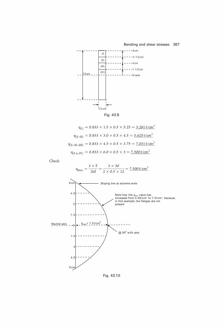
q�I� � 0:833� 1:5� 0:5� 5:25 � 3:281 t/cm2
q�I�II� � 0:833� 3:0� 0:5� 4:5 � 5:625 t/cm2
q�I�II�III� � 0:833� 4:5� 0:5� 3:75 � 7:031 t/cm2
q�I to IV� � 0:833� 6:0� 0:5� 3 � 7:500 t/cm2
Check:
qmax �3� F
2td� 3� 30
2� 0:5� 12� 7:500 t/cm2
Bending and shear stresses 367
Fig. 43.9
Fig. 43.10
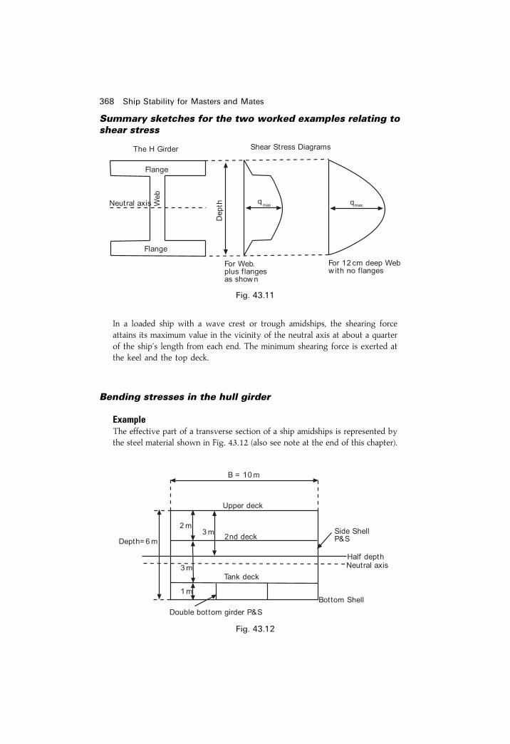
Summary sketches for the two worked examples relating toshear stress
In a loaded ship with a wave crest or trough amidships, the shearing forceattains its maximum value in the vicinity of the neutral axis at about a quarterof the ship's length from each end. The minimum shearing force is exerted atthe keel and the top deck.
Bending stresses in the hull girder
ExampleThe effective part of a transverse section of a ship amidships is represented bythe steel material shown in Fig. 43.12 (also see note at the end of this chapter).
368 Ship Stability for Masters and Mates
Fig. 43.11
Fig. 43.12

The beam of the ship is 10m and the depth is 6 m. All plating is 1.5 cm thick.Find the maximum tensile and compressive stresses when the ship is subjectedto a sagging moment of 6000 tonnes metres.Assume initially that Neutral Axis is at 1
2 depth, i.e. 3 m above base.
Depth of Neutral Axis below half depth � ÿ0:2250:81
� ÿ0:28mTotal second moment about half depth � 3:6375� 0:5425
� 4:18m4
Total second moment about neutral axis � 4:18ÿ 0:81� 0:282
INA � 4:18ÿ 0:06
� 4:12m4
Bending and shear stresses 369
Item Area (sq m) Lever Moment Lever I
Upper Deck 10� 0:015 � 0:15 3 0.45 3 1.352nd Deck 10� 0:015 � 0:15 1 0.15 1 0.15Tank Top 10� 0:015 � 0:15 ÿ 2 ÿ 0.30 ÿ 2 0.60Bottom Shell 10� 0:015 � 0:15 ÿ 3 ÿ 0.45 ÿ 3 1.35Sideshell 2� 6� 0:015 � 0:18 0 0 0 0P&S
Double Bottom 2� 1� 0:015 � 0:03 ÿ 2.5 ÿ 0.075 ÿ 2.5 0.1875Girders
0.81 ÿ 0.225 3.6375
g *Item Own inertia� 1
12 Ah2
Upper Deck 112� 0:15� 0:0152 � 2:8� 10ÿ6
2nd Deck 112� 0:15� 0:0152 � 2:8� 10ÿ6
Tank Top 112� 0:15� 0:0152 � 2:8� 10ÿ6
Bottom Shell 112� 0:15� 0:0152 � 2:8� 10ÿ6
Sideshell P&S 112� 0:18� 36 � 0:54
Double Bottom Girders 112� 0:03� 1 � 2500� 10ÿ6
0.5425
* It can be seen from this table that the second moment of area of horizontal members in thestructure such as decks, tank tops and outer bottom, about their own neutral axes are small and inpractice these values are ignored in the calculation.
��� ������� ���� ��� ������� ��� � �� ��� ����� ��� ������
�
�� �
�
� � � ����
��� � !� "
� �### ���� ��� $�
��� ������� ��� ��� ������� ��� � �� ��� ���� �����
� � ����
��� � �#
� !%�� ���� ��� $�
���� ������� ��� ��� ������� ��� � !%�� ���� ��� $��������� ���� ��� ������� ��� � �### ���� ��� $�
���������� ���� �������� �&� �� '��� �!�� � ���� ���� � �������� �� ������������ �������� ����� ��� ������� ��� �� � ������ ���� ����� �������� ���� ������ �� � ���� � ����������� ������� � ��� ������� �������� ��� ����� � ���� !�% � ��&� � ��� ()$�������� *�����
+��������,� �� � ��� �-. ���� ���� �� � � ������ ��� ������ ���� � � ���� �� ���� / �-. ���� ����� ��� ��� ��� ��� ���� ��� ������� ��� � �0��� ���� � ������� ����� �� ��� � ������� ��� � �� �1�����
&��� � ���� � ����� � �� �� ���� ���� �������/ ���� � ���� ����-2�
� ���� �� ��� ���� 2 $� � �� ������3 �4�� ��� � �� ���� ��� ��� ���� � � ��/ ���� � ���� �5��-2� � ���� �5 ��� ���� 2 $� � �� ������3 �4�� ��� ����� ������3 �4�� ��� � ����� ���� � �5�� 067� �� ����� � ���
������ � ��� � ������� ��� � ����� � ���� �� ����� �� � ��� �� �����/ � ����� �� ��� ������ ����������� ��� ���� ���� ��� ����������� �����
��� ���� ������� �� ������ �� ����

Bending and shear stresses 371
EXERCISE 43
1 The hull of a box-shaped vessel is 50m long and has a mass of 600 tonnes.The mass of the hull is uniformly distributed over its length. Machinery of200 tonnes mass extends uniformly over the quarter length amidships. Twoholds extending over the fore and aft quarter length each have 140 tonnesof cargo stowed uniformly over their lengths. Draw the curves of shearingforce and bending moments for this condition and state their maximumvalues.
2 A uniform box-shaped barge, 40m� 12m beam, is divided into four cargocompartments each 10m long. The barge is loaded with 600 tonnes of ironore, level stowed, as follows:
No. 1 hold N 135 tonnes, No. 2 hold N 165 tonnes,No. 3 hold N 165 tonnes, No. 4 hold N 135 tonnes
The loaded barge ¯oats in fresh water on an even keel at a draft of1.75m. Construct the curves of shearing force and bending moment forthis condition and also ®nd the position and value of the maximumbending moment for the still water condition.
3 A box-shaped vessel, 100m long, ¯oats on an even keel displacing 2000tonnes. The mass of the vessel alone is 1000 tonnes evenly distributed andshe is loaded at each end for a length of 25m with 500 tonnes of cargo,also evenly distributed. Sketch the curve of loads, shearing force andbending moments. Also state the maximum shearing force and bendingmoment and state where these occur.
4 Describe in detail Murray's Method for ascertaining the longitudinalbending moments in a ship when she is supported on a standard wavewith: (a) the crest amidships, and (b) the trough amidships. Include in youranswer details of what is meant by a `Standard Wave'.
5 A supertanker is 300m LOA. Second moment of area (INA) is 752m4.Neutral axis above the keel is 9.30m and 9.70m below the upper deck.Using the information in the table below, proceed to draw the Shear Forceand Bending Moment curves for this ship. From these two Strength curvesdetermine:(a) Maximum Shear Force in MN.(b) Maximum Bending Moment in MNm.(c) Position along the ship's length at which this maximum BM occurs.(d) Bending stress fmax in MN/m2 at the upper deck and at the keel.
Station Stern 1 2 3 4 5SF(MN) 0 26.25 73.77 115.14 114.84 21.12BM(MNm) 0 390 1887 4717 8164 10199
6 7 8 9 BowSF(MN) ÿ78:00 ÿ128:74 ÿ97:44 ÿ45:78 0BM(MNm) 9342 6238 2842 690 0
Chapter 44
Simpli®ed stabilityinformationDEPARTMENT OF TRADE MERCHANT SHIPPING NOTICE NO. 1122
SIMPLIFIED STABILITY INFORMATIONNotice to Shipowners, Masters and Shipbuilders
1 It has become evident that the masters' task of ensuring that his shipcomplies with the minimum statutory standards of stability is in manyinstances not being adequately carried out. A feature of this is that unduetraditional reliance is being placed on the value of GM alone, while otherimportant criteria which govern the righting lever GZ curve are notbeing assessed as they should be. For this reason the Department,appreciating that the process of deriving and evaluating GZ curves isoften dif®cult and time-consuming, strongly recommends that in futuresimpli®ed stability information be incorporated into ships' stabilitybooklets. In this way masters can more readily assure themselves thatsafe standards of stability are met.
2. Following the loss of the Lairds®eld, referred to in Notice M.627, theCourt of Inquiry recommended that simpli®ed stability information beprovided. This simpli®ed presentation of stability information has beenadopted in a large number of small ships and is considered suitable forwider application in order to overcome the dif®culties referred to inparagraph 1.
3. Simpli®ed stability information eliminates the need to use cross curves ofstability and develop righting lever GZ curves for varying loadingconditions by enabling a ship's stability to be quickly assessed, to showwhether or not all statutory criteria are complied with, by means of asingle diagram or table. Considerable experience has now been gainedand three methods of presentation are in common use. These are:
(a) The Maximum Deadweight Moment Diagram or Table,(b) The Minimum Permissible GM Diagram or Table,(c) The Maximum Permissible KG Diagram or Table.

In all three methods the limiting values are related to salt waterdisplacement or draft. Free surface allowances for slack tanks arehowever applied slightly differently.
4 Consultation with the industry has revealed a general preference for theMaximum Permissible KG approach, and graphical presentation alsoappears to be preferred rather than a tabular format. The Department'sview is that any of the methods may be adopted subject to:
(a) clear guidance notes for their use being provided and(b) submission for approval being made in association with all other
basic data and sample loading conditions.
In company ¯eets it is however recommended that a single method beutilized throughout.
5 It is further recommended that the use of a Simpli®ed Stability Diagram asan adjunct to the Deadweight Scale be adopted to provide a direct meansof comparing stability relative to other loading characteristics. Standardwork forms for calculating loading conditions should also be provided.
6 It is essential for masters to be aware that the standards of stabilityobtainable in a vessel are wholly dependent on exposed openings such ashatches, doorways, air pipes and ventilators being securely closedweathertight; or in the case of automatic closing appliances such asairpipe ball valves that these are properly maintained in order to functionas designed.
7 Shipowners bear the responsiblity to ensure that adequate, accurate andup-to-date stability information for the master's use is provided. Itfollows that it should be in a form which should enable it to be readilyused in the trade in which the vessel is engaged.
Maximum Permissible Deadweight Moment DiagramThis is one form of simpli®ed stability data diagram in which a curve ofMaximum Permissible Deadweight Moments is plotted againstDisplacement in tonnes on the vertical axis and Deadweight Moment inTonnes metres on the horizontal axis, the Deadweight Moment being themoment of the Deadweight about the keel.The total Deadweight Moment at any Displacement must not, under any
circumstances, exceed the Maximum Permissible Deadweight Moment atthat Displacement.Diagram 3 (Figure 44.1) illustrates this type of diagram. The ship's
Displacement in tonnes is plotted on the vertical axis from 1500 to 4000tonnes while the Deadweight Moments in tonnes metres are plotted on thehorizontal axis. From this diagram it can be seen that, for example, theMaximum Deadweight Moment for this ship at a displacement of 3000tonnes is 10 260 tonnes metres (Point 1). If the light displacement for thisship is 1000 tonnes then the Deadweight at this displacement is 2000tonnes. The maximum kg for the Deadweight tonnage is given by:
Simpli®ed stability information 373

Maximum kg � Deadweight Moment
Deadweight
� 10 260
2000
� 5:13m
Example 1Using the Simpli®ed Stability Data shown in Diagram 3 (Figure 44.1), estimatethe amount of cargo (kg 3m) which can be loaded so that after completion ofloading the ship does not have de®cient stability. Prior to loading the cargo thefollowing weights were already on board:
250 t fuel oil kg 0.5m Free Surface Moment 1400 tm50 t fresh water kg 5.0m Free Surface Moment 500 t m
2000 t cargo kg 4.0 m
The light displacement is 1000 t, and the loaded Summer displacement is 3500 t
Since 10 875 tonnes metres is less than the maximum permissible deadweightmoment at a displacement of 3500 tonnes, the ship will not have de®cientstability and may load 200 tonnes of cargo.
Ans. Load 200 tonnes.
Example 2Using the Maximum Permissible Deadweight Moment diagram 3 (Figure 44.1)and the information given below, ®nd the quantity of timber deck cargo (Kg8.0 m) which can be loaded, allowing 15 per cent for water absorption duringthe voyage.
374 Ship Stability for Masters and Mates
Item Weight Kg Deadweight Moment
Light disp. 1000 t ± ±Fuel oil 250 t 0.5 m 125 t mFree surface ± ± 1400 t mFresh water 50 t 5.0 m 250 t mFree surface ± ± 500 t mCargo 2000 t 4.0 m 8000 t m
Present cond. 3300 t 10 275 t mÿ Point 2(Satisfactory)
Maximum balance 200 t 3.0 m 600 t m
Summer displ. 3500 10 875 t mÿ Point 3(Satisfactory)

Simpli®ed stability information 375
Fig. 44.1

Summer displacement 4000 tonnes, Light Displacement 1000 tonnes.Weights already on board:
Fuel oil 200 tonnes, Kg 0.5 m, free surface moment 1400 tm
Fresh water 40 tonnes, Kg 5.0m, free surface moment 600 t m
Cargo 2000 tonnes, Kg 4.0 m
Ballast 350 tonnes, Kg 0.5 m
The following weights will be consumed during the voyage:
Fuel oil 150 tonnes, Kg 0.5 m. Free surface moment will be
reduced by 800 t m
Fresh water 30 tonnes, Kg 5.0m. Free surface moment will be
by 200 t m
Departure Condition
From diagram 3, where the line joining points 4 and 5 cuts the curve ofMaximum Permissible Deadweight Moments (point 6), the displacement is3920 tonnes.
Total departure displacement 3920 tonnes
Departure displacement without deck cargo 3590 tonnes
; Max deck cargo to load 330 tonnes
Absorption during voyage � 15
100� 330 � 49:5 tonnes
376 Ship Stability for Masters and Mates
Item Weight Kg Deadweight Moment
Light ship 1000 ± ±Fuel oil 200 0.5 100Free surface 1400Fresh water 40 5.0 200Free surface 600Cargo 2000 4.0 8000Ballast 350 0.5 175Departure Disp. (withoutdeck cargo) 3590 10 475 ± Point 4
(Satisfactory)Maximum deck cargo 410 8.0 3280
Summer disp. 4000 13 755 ± Point 5(De®cient Stability)
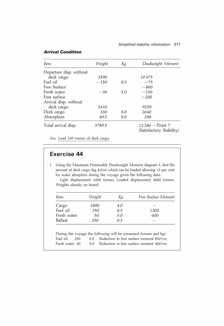
Arrival Condition
Ans. Load 330 tonnes of deck cargo.
Simpli®ed stability information 377
Item Weight Kg Deadweight Moment
Departure disp. withoutdeck cargo 3590 10 475
Fuel oil ÿ 150 0.5 ÿ75Free Surface ÿ800Fresh water ÿ30 5.0 ÿ150Free surface ÿ200Arrival disp. withoutdeck cargo 3410 9250
Deck cargo 330 8.0 2640Absorption 49.5 8.0 396
Total arrival disp. 3789.5 12 286 ± Point 7(Satisfactory Stability)
Exercise 44
1 Using the Maximum Permissible Deadweight Moment diagram 3, ®nd theamount of deck cargo (kg 8.0 m) which can be loaded allowing 15 per centfor water absoption during the voyage given the following data:
Light displacement 1000 tonnes, Loaded displacement 4000 tonnes.Weights already on board:
During the voyage the following will be consumed (tonnes and kg):Fuel oil 250 0.5 Reduction in free surface moment 850 t m.Fresh water 40 5.0 Reduction in free surface moment 400 t m.
Item Weight Kg Free Surface Moment
Cargo 1800 4.0 ±Fuel oil 350 0.5 1200Fresh water 50 5.0 600Ballast 250 0.5 ±
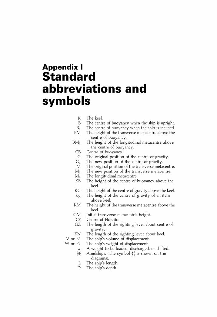
Appendix I
Standardabbreviations andsymbols
K The keel.B The centre of buoyancy when the ship is upright.B1 The centre of buoyancy when the ship is inclined.
BM The height of the transverse metacentre above thecentre of buoyancy.
BML The height of the longitudinal metacentre abovethe centre of buoyancy.
CB Centre of buoyancy.G The original position of the centre of gravity.G1 The new position of the centre of gravity.M The original position of the transverse metacentre.M1 The new position of the transverse metacentre.ML The longitudinal metacentre.KB The height of the centre of buoyancy above the
keel.KG The height of the centre of gravity above the keel.Kg The height of the centre of gravity of an item
above keel.KM The height of the transverse metacentre above the
keel.GM Initial transverse metacentric height.CF Centre of Flotation.GZ The length of the righting lever about centre of
gravity.KN The length of the righting lever about keel.
V or j The ship's volume of displacement.W or i The ship's weight of displacement.
w A weight to be loaded, discharged, or shifted.�e� Amidships. (The symbol �e� is shown on trim
diagrams).L The ship's length.D The ship's depth.

B The ship's maximum beam.d The ship's draft.F Forward, or centre of ¯otation.A Aft.
M or m Metres.Cw The water-plane coef®cient.Cb Block coef®cient.Cm Coef®cient of midships area.Cp Prismatic coef®cient.
I or i Second moment of an area.l The distance of the centre of ¯otation from aft.P The upthrust on the keel blocks when drydocking.m The permeability of a compartment.
WL The original waterline.W1L1 The new waterline.
Gv The virtual centre of gravity.t The trim.
MCTC or MCT 1 cm The moment to change the trim by 1 cm.TPC The tonnes per centimetre immersion.GML The longitudinal metacentric height.SG Speci®c gravity.y An angle of list or heel.
WPA Area of a water-plane.FWA Fresh water allowance.FW Fresh water.SW Salt water.CDB Cellular double-bottom tank.
CI or h The common interval used in Simpson's Rules.E Young's Modulus.y Depth from the neutral layer.f Stress.q Shearing stress.r Density in tonnes/m3.rFW Fresh water density @ 1.000 t/m3.rSW Salt water density @ 1.025 t/m3.rDW Dock water density as given in t/m3.dmax Maximum squat.
S Blockage factor.y Static underkeel clearance.y2 Dynamical underkeel clearance.H Water depth relating to squat.T Ship's mean draft relating to squat.Vk Speed of ship relative to the water.
Standard abbreviations and symbols 379

Appendix II
Summary of stabilityformulae*
Form Coef®cients
Area of waterplane � L� B� Cw
Area of amidships � B� d� Cm
Volume of displacement � L� B� d� Cb
Cb � Cm � Cp
DraftsWhen displacement is constant: (For box-shapes):
New draft
Old draft� Old density
New density
When draft is constant:
New displacementOld displacement �
New densityOld density
TPC � WPA
97:56
FWA � W
4� TPC
Change of draft or � FWA �1025ÿ rDW�25Dock Water Allowance
Homogeneous log:
draft
depth� relative density of log
relative density of water
* See note on page 386.

Variable immersion hydrometer:
Density � My
My ÿ x
�MyÿMx
L
�Trim
MCTC � W� GML
100� L
Change of trim � Trimming moment
MCTC
Change of draft aft � l
L� Change of trim
Change of draft forward � Change of trim
ÿ Change of draft aft
Effect of trim on tank soundings:
Head when full
Length of tank� Trim
Length of ship
True Mean Draft:
Correction
FY� Trim
Length
To Keep the Draft Aft Constant:
d � MCTC� L
TPC� l
To ®nd GML:
GML
GG1� L
t
Simpson's Rules1st Rule:
Area � h/3 (a� 4b� 2c� 4d� e) or 13� CI� S1
2nd Rule:
Area � 3h/8 (a� 3b� 3c� 2d� 3e� 3f � g) or 38� CI� S2
3rd Rule:
Area � h/12 (5a� 8bÿ c) or 112� CI� S3
Summary of stability formulae 381

KB and BM
Transverse StabilityFor rectangular waterplanes:
I � LB3
12
BM � I/V
For box-shapes:
BM � B2/12d
KB � d/2
KMmin � B=���6p
For triangular prisms:
BM � B2/6d
KB � 2d/3
Depth of centre of buoyancy � 1
3
�d
2� V
A
�below the waterline
Longitudinal StabilityFor rectangular waterplanes:
IL � BL3
12
BML � ILV
For box-shapes:
BML � L2/12d
For triangular prisms:
BML � L2
6d
Transverse Statical Stability
Moment of Statical Stability � W� GZ
At Small Angles of Heel:
GZ � GM� sin y
382 Ship Stability for Masters and Mates

By Wall-Sided Formula:
GZ � �GM� 12 BM tan2 y� sin y
By Attwood's Formula:
GZ � v� hh1V
ÿ BG sin y
Stability Curves:
New GZ � Old GZ� GG1 sin Heel or
New GZ � KNÿ KG sin Heel
Dynamical Stability � W� Area under stability curve
� Wv(gh� g1h1)
Vÿ BG(1ÿ cos y)
� �
List
Final KG � Final Moment
Final Displacement
GG1 � w� d
Final W
tan List � GG1
GM
Increase in draft due to list:
New draft � 12 EbEsin y� (dÿ r� cos y
Inclining Experiment:
GM
GG1� Length of plumbline
Deflection
Effect of Free Surface
Virtual loss of GM � lb3
12� rW� 1
n2
Drydocking and GroundingUpthrust at Stern:
P � MCTC� t
l
or P � Oldÿ New displacement
Summary of stability formulae 383
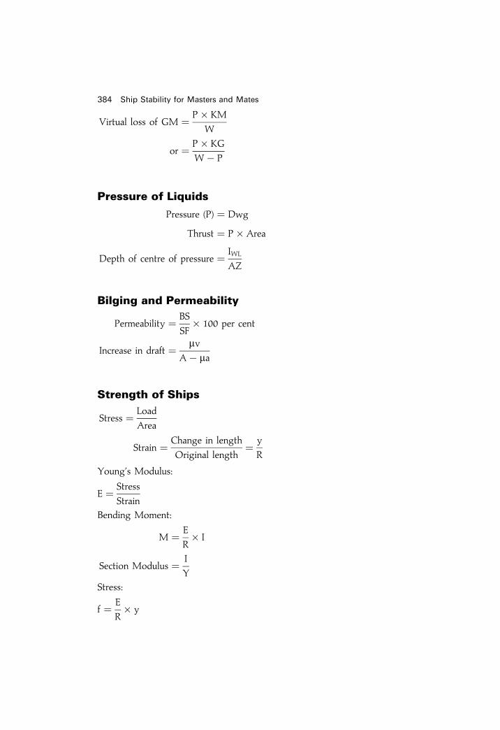
Virtual loss of GM � P� KM
W
or � P� KG
Wÿ P
Pressure of Liquids
Pressure (P) � Dwg
Thrust � P� Area
Depth of centre of pressure � IWL
AZ
Bilging and Permeability
Permeability � BS
SF� 100 per cent
Increase in draft � mvAÿ ma
Strength of Ships
Stress � Load
Area
Strain � Change in length
Original length� y
R
Young's Modulus:
E � Stress
Strain
Bending Moment:
M � E
R� I
Section Modulus � I
Y
Stress:
f � E
R� y
384 Ship Stability for Masters and Mates

�������� ����
� � ������
���� �����
�������� ����� � �� ��� �
���� � �� � ����� � �!���!�
�� � �� ��! � �� � ����
�� �"�� #����
���� � �� � !�
���
�� ���$��% ��������
���� � �� � !�
&�
'�%� �� ����(���� � )�)� !� ��� ���!
��� ���������� �� *����
�� ���� �����������!+,
�,
�+, � !� ������ +,
�� ����
���� -(� � �(������
�� ���� � .! � �+����+,
/������ 0����%�
� � !� ����������������+,� � !���������
+,� �""���1
������� �� ��� �� ����� �� ���

Zero GM:
tan list �������������������2EwEdW� BM
3
rTheorem of Parallel Axes:
ICG � IOZ ÿ Ay2
or INA � Ixx ÿ Ay2
SummaryAlways write your formula ®rst in letters. If you then make a mathematicalerror you will at least obtain some marks for a correct formula.
386 Ship Stability for Masters and Mates

Appendix III
Conversion tablesMetric-Imperial Imperial-Metric
1m � 3:281 ft
1m � 39:37 ins
1m2 � 10:764 ft2
1m3 � 11:77 ft3
1 litre � 61:02 ins3
1 litre � 1:76 pints
1 litre � 0:22 galls
1 tonne � 0:985 tons
1 kg � 2:205 lbs
1m3=tonne � 35:88 ft3=ton
1 litre=kg � 0:016 ft3=lb
1000 kg=m3 � 1000 oz=ft3
1025 kg=m3 � 1025 oz=ft3
1 ft � 0:3048m
1 in � 25:4mm
1 ft2 � 0:0929m2
1 in2 � 645:2mm2
40 ft3 � 1:133m3
100 ft3 � 2:832m3
1 ft3 � 0:02832m3
1 gall � 4:5461 litres
1 t � 1:016 tonne
1 lb � 0:4536 kg
1 cwt � 50:80 kg
1 ft3=t � 0:02787m3=tonne
1 ft3=lb � 62:428 litres=kg
1000 oz=ft3 � 1000 kg=m3
1025 oz=ft3 � 1025 kg=m3
TPI 00 � 0:4 � TPC
MCTI 00 � 0:12 � MCTC
1 ton=in2 � 15:444 � 1MN=m2
1 lbf � 4:448N
MN=m2 � 100 � tonnes=m2

Appendix IV
Extracts from theM.S. (Load Lines)Rules, 1968
Part V
GENERAL
Information as to stability of ships30.-(1) The owner of any ship to which freeboards are assigned under theseRules shall provide for the guidance of the master of the ship informationrelating to the stability of the ship in accordance with the followingprovisions of this Rule.
(2) Except as otherwise provided in paragraph (6) of this Rule, suchinformation shall include particulars appropriate to the ship in respect ofall matters speci®ed in Schedule 7 to these Rules and shall be in the formrequired by that Schedule.
(3) Subject to the following paragraph, the information shall, when ®rstsupplied, be based on the determination of stability by means of aninclining test which shall unless the Board otherwise permits be carriedout in the presence of a surveyor appointed by the Board. The information®rst supplied shall be replaced by fresh information whenever its accuracy ismaterially affected by alteration of the ship. Such fresh information shall ifthe Board so require be based on a further inclining test.
(4) The Board may:(a) in the case of any ship allow the information to be based on the
determination, by means of an inclining test, of the stability of a sistership;
(b) in the case of a ship specially designed for the carriage of liquids orore in bulk; or of any class of such ships, dispense with an incliningtest if satis®ed from the information available in respect of similarships that the ship's proportions and arrangements are such as toensure more than suf®cient stability in all probable loading con-ditions.

(5) The information, and any fresh information to replace the samepursuant to paragraph (3) of this Rule, shall before issue to the master besubmitted by or on behalf of the owner of the ship to the Board for theirapproval, together with a copy thereof for retention by the Board, and shallincorporate such additions and amendments as the Board may in anyparticular case require.
(6) (a) The owner of any ship which, by virtue of the Merchant Shipping(Load Lines) (Transitional Provisions) Regulations 1968, is to betreated as a ship to which freeboards have been assigned underthese Rules shall provide for the information of the master suchinformation relating to the stability of the ship as was required to beso provided under the law in force immediately prior to the cominginto operation of these Rules (a).
(b) The requirement in the preceding sub-paragraph shall have effect inrelation to any ship to which it applies until the date on which theload line certi®cate currently in force in respect of the ship on thedate these Rules come into operation ceases to be valid.
(7) Information provided pursuant to the foregoing provisions of this Ruleshall be furnished by the owner of the ship to the master in the form of abook which shall be kept on the ship at all times in the custody of themaster.
Information as to loading and ballasting of ships31.-(1) The owner of any ship to which freeboards are assigned under theseRules, being a ship of more than 150 metres in length specially designed forthe carriage of liquids or ore in bulk, shall provide for the information of themaster information relating to the loading and ballasting of the ship inaccordance with the following provisions of this Rule.
(2) Such information shall consist of working instructions specifying indetail the manner in which the ship is to be loaded and ballasted so as toavoid the creation of unacceptable stresses in her structure and shall indicatethe maximum stresses permissible for the ship.
(3) The provisions of paragraph (5) of the preceding Rule shall have effectin respect of information required under this Rule, and the information dulyapproved in accordance with that paragraph shall be contained in the bookto be furnished to the master of the ship pursuant to paragraph (7) of thatRule, so however that the information to be provided pursuant to each Ruleis separately shown in the book under separate headings specifying thenumber and heading of each Rule.
Extracts from the M.S. (Load Lines) Rules, 1968 389

Part 1
SHIPS IN GENERAL
Structural Strength and Stability
2.-(1) The construction of the ship shall be such that her general structuralstrength will be suf®cient for the freeboards to be assigned to her.(a) See section 18 of the Merchant Shipping (Safety Convention) Act
1949 (12,13 & 14 Geo. 6 c 43.) and section 14 of the MerchantShipping Act 1964 (1964 c 47).
(2) The design and construction of the ship shall be such as to ensure thather stability in all probable loading conditions will be suf®cient for thefreeboards to be assigned to her, and for this purpose regard shall be had, inaddition to the intended service of the ship and to any relevantrequirements of Rules made under the Merchant Shipping (SafetyConvention) Act 1949(a) and the Merchant Shipping Act 1964(b), to thefollowing criteria:(a) The Area under the curve of Righting Levers (GZ curve) shall not be
less than:(i) 0.055 metre-radians up to an angle of 30 degrees;(ii) 0.09 metre-radians up to an angle of either 40 degrees or the
angle at which the lower edges of any openings in the hull,superstructures or deckhouses, being openings which cannot beclosed weathertight, are immersed if that angle be less;
(iii) 0.03 metre-radians between the angles of heel of 30 degrees and40 degrees or such lesser angle as is referred to in (ii).
(b) The Righting Lever (GZ) shall be at least 0.20 metres at an angle ofheel equal to or greater than 30 degrees.
(c) The maximum Righting Lever (GZ) shall occur at an angle of heel notless than 30 degrees.
(d) The initial transverse metacentric height shall not be less than 0.15metres. In the case of a ship carrying a timber deck cargo whichcomplies with sub-paragraph (a) by taking into account the volumeof timber deck cargo the initial transverse metacentric height shallnot be less than 0.05 metres.
(3) To determine whether the ship complies with the requirements of sub-paragraph (2) the ship shall, unless the Board otherwise permit, be subjectedto an inclining test carried out in the presence of a surveyor appointed bythe Board, and the Board shall notify the Assigning Authority whether ornot they are satis®ed that the ship complies with those requirements.(a) 1949 12, 13 & 14 Geo. 6 c. 43.(b) 1964 c. 47.
390 Ship Stability for Masters and Mates

SCHEDULE 7
Information as to Stability of Ships(Rule 30)
The information relating to the stability of a ship to be provided for themaster pursuant to Rule 30 of these Rules shall include particularsappropriate to the ship of the matters speci®ed below. Such particularsshall be in the form of a statement unless the contrary is indicated.
1. The ship's name, of®cial number, port of registry, gross and registertonnages, principal dimensions, displacement, deadweight and draft to theSummer load line.
2. A pro®le view and, if the Board so require in a particular case, plan viewsof the ship drawn to scale showing with their names all compartments,tanks, storerooms and crew and passenger accommodation spaces, and alsoshowing the mid-length position.
3. The capacity and the centre of gravity (longitudinally and vertically) ofevery compartment available for the carriage of cargo, fuel, stores, feedwater domestic water or water ballast. In the case of a vehicle ferry, thevertical centre of gravity of compartments for the carriage of vehicles shallbe based on the estimated centres of gravity of the vehicles and not on thevolumetric centres of the compartments.
4. The estimated total weight of (a) passengers and their effects and (b)crew and their effects, and the centre of gravity (longitudinally andvertically) of each such total weight. In assessing such centres of gravitypassengers and crew shall be assumed to be distributed about the ship inthe spaces they will normally occupy, including the highest decks to whicheither or both have access.
5. The estimated weight and the disposition and centre of gravity of themaximum amount of deck cargo which the ship may reasonably beexpected to carry on an exposed deck. The estimated weight shall includein the case of deck cargo likely to absorb water the estimated weight ofwater likely to be so absorbed and allowed for in arrival conditions, suchweight in the case of timber deck cargo being taken to be 15 per cent byweight.
6. A diagram or scale showing the load line mark and load lines withparticulars of the corresponding freeboards, and also showing the displace-ment, metric tons per centimetre immersion, and deadweight correspondingin each case to a range of mean draughts extending between the waterlinerepresenting the deepest load line and the waterline of the ship in lightcondition.
7. A diagram or tabular statement showing the hydrostatic particulars ofthe ship, including:(1) the heights of the transverse metacentre and(2) the values of the moment to change trim one centimetre,
Extracts from the M.S. (Load Lines) Rules, 1968 391

for a range of mean drafts extending at least between the waterlinerepresenting the deepest load line and the waterline of the ship in lightcondition. Where a tabular statement is used, the intervals between suchdrafts shall be suf®ciently close to permit accurate interpolation. In the caseof ships having raked keels, the same datum for the heights of centres ofbuoyancy and metacentres shall be used as for the centres of gravityreferred to in paragraphs 3, 4 and 5.
8. The effect on stability of free surface in each tank in the ship in whichliquids may be carried, including an example to show how the metacentricheight is to be corrected.
9.-(1) A diagram showing cross curves of stability indicating the height ofthe assumed axis from which the Righting Levers are measured and the trimwhich has been assumed. In the case of ships having raked keels, where adatum other than the top of keel has been used the position of the assumedaxis shall be clearly de®ned.
(2) Subject to the following sub-paragraph, only (a) enclosed super-structures and (b) ef®cient trunks as de®ned in paragraph 10 of Schedule5 shall be taken into account in deriving such curves.
(3) The following structures may be taken into account in deriving suchcurves if the Board are satis®ed that their location, integrity and means ofclosure will contribute to the ship's stability:(a) Superstructures located above the superstructure deck;(b) deckhouses on or above the freeboard deck, whether wholly or in
part only;(c) hatchway structures on or above the freeboard deck.
Additionally, in the case of a ship carrying timber deck cargo, the volumeof the timber deck cargo, or a part thereof, may with the Board's approvalbe taken into account in deriving a supplementary curve of stabilityappropriate to the ship when carrying such cargo.
(4) An example shall be given showing how to obtain a curve of RightingLevers (GZ) from the cross curves of stability.
(5) Where the buoyancy of a superstructure is to be taken into account inthe calculation of stability information to be supplied in the case of a vehicleferry or similar ship having bow doors, ship's side doors or stern doors,there shall be included in the stability information a speci®c statement thatsuch doors must be secured weather-tight before the ship proceeds to seaand that the cross curves of stability are based upon the assumption thatsuch doors have been so secured.
10.-(1) The diagram and statements referred to in sub-paragraph (2) of thisparagraph shall be provided separately for each of the following conditionsof the ship:-(a) Light condition. If the ship has permanent ballast, such diagram and
statements shall be provided for the ship in light condition both (i)with such ballast, and (ii) without such ballast.
392 Ship Stability for Masters and Mates

(b) Ballast condition, both (i) on departure, and (ii) on arrival, it beingassumed for the purpose of the latter in this and the following sub-paragraphs that oil fuel, fresh water, consumable stores and the likeare reduced to 10 per cent of their capacity.
(c) Condition both (i) on departure, and (ii) on arrival, when loaded tothe Summer load line with cargo ®lling all spaces available for cargo,cargo for this purpose being taken to be homogeneous cargo exceptwhere this is clearly inappropriate, for example in the case of cargospaces in a ship which are intended to be used exclusively for thecarriage of vehicles or of containers.
(d) Service loaded conditions, both (i) on departure and (ii) on arrival.
(2) (a) A pro®le diagram of the ship drawn to a suitable small scaleshowing the disposition of all components of the deadweight.
(b) A statement showing the lightweight, the disposition and the totalweights of all components of the deadweight, the displacement, thecorresponding positions of the centre of gravity, the metacentre andalso the metacentric height (GM).
(c) A diagram showing a curve of Righting Levers (GZ) derived from thecross curves of stability referred to in paragraph 9. Where credit isshown for the buoyancy of a timber deck cargo the curve ofRighting Levers (GZ) must be drawn both with and without thiscredit.
(3) The metacentric height and the curve of Righting Levers (GZ) shall becorrected for liquid free surface.
(4) Where there is a signi®cant amount of trim in any of the conditionsreferred to in sub-paragraph (1) the metacentric height and the curve ofRighting Levers (GZ) may be required to be determined from the trimmedwaterline.
(5) If in the opinion of the Board the stability characteristics in either orboth of the conditions referred to in sub-paragraph (1)(c) are notsatisfactory, such conditions shall be marked accordingly and an appro-priate warning to the master shall be inserted.
11. Where special procedures such as partly ®lling or completely ®llingparticular spaces designated for cargo, fuel, fresh water or other purposesare necessary to maintain adequate stability, a statement of instructions asto the appropriate procedure in each case.
12. A copy of the report on the inclining test and of the calculationtherefrom of the light condition particulars.
Merchant Shipping (Safety Convention) Act, 1949
Section 18-( 1) There shall be carried on board every British ship registeredin the United Kingdom whose keel is laid after the commencement of this
Extracts from the M.S. (Load Lines) Rules, 1968 393

Act such information in writing about the ship's stability as is necessary forthe guidance of the master in loading and ballasting the ship.
(2) The said information shall be in such a form as may be approved by theMinister (who may approve the provision of the information in the form ofa diagram or drawing only), and shall be based on the determination of theship's stability by means of an inclining test of the ship:Provided that the Minister may allow the information to be based on a
similar determination of the stability of a sister ship.
(3) When any information under this section is provided for any ship, theowner shall send a copy thereof to the Minister:Provided that the owner shall not be required to send a copy of any
information to the Minister if a previous copy of the same information hasbeen sent to the Minister.
(4) If any such ship proceeds, or attempts to proceed, to sea without suchinformation as aforesaid on board, the owner or master of the ship shall beliable to a ®ne not exceeding one hundred pounds; and if the owner of anyship contravenes the last preceding subsection, he shall be liable to a like®ne.
(5) It is hereby declared that for the purposes of section two hundred and®fty-eight of the principal Act (which requires documents relating tonavigation to be delivered by the master of a ship to his successor)information under this section shall be deemed to be a document relating tothe navigation of the ship.
Section 29-(l) Nothing in this Act:(c) requiring information about a ship's stability to be carried on board;
shall, unless in the case of information about a ship's stability theMinister otherwise orders, apply to any troopship, pleasure yacht or®shing vessel, or to any ship of less than ®ve hundred tons grosstonnage other than a passenger steamer or to any ship notpropelled by mechanical means.
394 Ship Stability for Masters and Mates

Appendix V
Department ofTransport Syllabuses(Revised April 1995)*Supplied kindly by Marine Safety Agency (MSA) of Southampton andScottish Quali®cations Authority (SQA) of Glasgow.
CLASS 5 CERTIFICATE OF COMPETENCY
General Ship Knowledge ± MSA/SQA(a) General ideas on ship construction and on plans available on board
ship.General pumping arrangements.General de®nition of main dimensions.The names of the principal parts of a ship.
(b) General understanding of:Displacement;Deadweight;Buoyancy; Reserve buoyancy.
Use of displacement and tonnes per centimetre immersion scales todetermine weight of cargo or ballast from draughts or freeboard.Load line marks.Effect of density of water on draught and freeboard.Fresh water allowance.
(c) (i) General understanding of:Centre of gravityCentre of buoyancyMetacentric heightRighting leverRighting moment
(ii) The use of stability and hydrostatic data supplied to ships,including stability data in simpli®ed form.
* All of these syllabuses to be reviewed and possibly revised by MSA in 1999/2000.
The effect of adding and removing weights. The danger of slacktanks.
(iii) Rigging a ship for loading and discharging cargo, the use ofderricks, winches and cranes.`Lining up' pipelines on oil products carriers.The stowage and securing of cargoes including bulk cargoes.Grain cargoes, timber cargoes and ro-ro cargoes. A knowledge ofthe safety precautions to be taken during the loading anddischarging of bulk oil, chemicals and other dangerous commod-ities.Ventilation systems of holds and tanks. Entry into enclosed spaces.
CLASS 4 CERTIFICATE OF COMPETENCY
General Ship Knowledge ± BTEC/SQA/HND Part 1(a) General ideas on ship construction and on plans available onboard ship.
General de®nitions of main dimensions.The names of the principal parts of a ship.
The candidate will be expected to show his practical acquaintance with:Longitudinal and transverse framingBeams and beam kneesWatertight bulkheadsHatchways and closing appliancesRuddersSteering gearShell and deck platingDouble bottoms and peak tanksBilgesSide and wing tanksStern framesPropellers and propeller shaftsStern tubesSounding pipesAir pipesGeneral pumping arrangementsThe stiffening and strengthening to resist panting, pounding andlongitudinal stresses.Cause and prevention of corrosion in a ship's structure.
(b) General ideas on welding, riveting and burning and the precautions tobe taken when such processes are carried out aboard ship.
(c) (i) The meaning of the terms: Block co-ef®cient; Displacement;Deadweight.
(ii) Density, relative density; Principle of Archimedes; ¯otation. Effectof density of water on draught and freeboard. Fresh waterallowance. The marine hydrometer and its uses.
396 Ship Stability for Masters and Mates

(d) Care and maintenance of all life saving and ®re ®ghting appliances,lights and sound signalling apparatus.
(e) The computation of areas by Simpson's First and Second Rules.
CLASS 4 CERTIFICATE OF COMPETENCY
Cargo Operations and Stability ± MSA/SQA(a) Use of displacement and tonnes per centimetre immersion scales to
determine weight of cargo or ballast from draughts or freeboard.Load line-marks.Buoyancy; Reserve buoyancy; understanding of fundamental actions tobe taken in the event of partial loss of intact buoyancy.
(b) (i) General understanding with de®nitions of:Centre of gravity, stable, unstable and neutral equilibrium.Centre of buoyancyMetacentric heightRighting leverRighting moment
(ii) The use of stability and hydrostatic data supplied to ships.The effect of adding and removing weights.The danger of slack tanks. Security of hatches.
(iii) Rigging a ship for loading and discharging cargo, the use ofderricks, winches and cranes.`Lining up' pipelines on oil products carriers.The stowage, separation and dunnaging of cargoes including bulkcargoes, timber cargoes; grain cargoes, ro-ro cargoes.Causes of sweating, and precautions to be taken before, duringand after stowing to prevent damage by sweat.A knowledge of the safety precautions to be taken during theloading and discharge of bulk oil, chemicals and other dangerouscommodities, Calculations of weight capacities taken up by partcargoes and of space remaining.Conversion of weight measurement of cargo into space measure-ment and vice versa.The making and use of cargo plans.Ventilation and systems of holds and tanks.Precautions to be taken before entering cargo and ballast tanksand void spaces. The carriage of passengers and livestock.
CLASS 2 CERTIFICATE OF COMPETENCY
Ship Construction ± BTEC/SQA/HND(a) Types of ships. General ideas on strength and construction in relation
to particular trades, including specialised carriers.
Department of Transport Syllabuses 397

The use of special steels, aluminium and ®re resistant materials in shipconstruction.
(b) Midship sections of single deck and 'tween deck ships, including bulkcarriers, container ships and specialised carriers. Functions, constructionand stiffening of watertight bulkheads, including collision bulkhead.Structure at the stern, construction, stiffening and closing arrangementsof hatchways and superstructures, tank openings, watertight and hulldoors.
(c) General ideas on welding processes in construction and repair work,types of weld, common faults, visual examination of welded work.Testing of tanks and other watertight work.Methods of corrosion control.
(d) Stresses produced by shear and bending. To produce simple curves ofload, shear force and bending moments. Torsional stress. Modernmethods of determining the effect of different conditions of loadingand ballasting on the ship's structure. Methods of compensating fordiscontinuity of strength. Local and speci®c stiffening.
(e) Classi®cation of ships; periodic surveys for retention of class. TheCargo Ship Construction and Survey Rules and surveys required underthe Rules.
CLASS 2 CERTIFICATE OF COMPETENCY
Ship Stability ± MSA/SQA(a) Determination of the position of the centre of gravity of a ship for
different conditions of loading and ballasting. The effect on the positionof the centre of gravity of adding, removing, shifting or suspendingweights. To determine the virtual rise in the position of the centre ofgravity due to slack tanks. Transverse and longitudinal metacentres,metacentric height. Initial stability and its limitation to small angles ofinclination. Changes in stability during a voyage. Effects of a shift ofcargo or solid ballast. Stiff and tender ships.
(b) Changes of trim and draught due to loading, discharging and shiftingweights. Effects of list and trim on stability. Stability and trim whendrydocking.
(c) Stability to moderate for large angles of heel; assessment of dynamicalstability from GZ curve; angle of loll; shifting or adding weights withzero GM; effect of wind and wave excitation.
(d) Dangers to a ship with a heavy list. Precautions when righting. Deckcargoes, homogeneous cargo and cargo liable to shift. Ballasting forstability consideration. The effect of beam and freeboard on stability.
(e) The inclining experiment. A comprehensive knowledge of the hydro-static, stability and stress data supplied to ships.
(f) An understanding of the factors affecting the shape of a curve ofstatical stability and the signi®cance of the area under the curve,including its calculation. Use of simpli®ed data. Grain shift moments.
398 Ship Stability for Masters and Mates

(g) Principles of damage control in passenger ships and ro-ro vessels.Arrangement for restricting the spread of ®re in superstructures.
(h) Requirements of the Load Line Rules, period and conditions of validityof certi®cate, an understanding of those aspects of the conditions ofassignment which affect the stability and seaworthiness of a ship.Knowledge of the principles underlying the assignment of passengership subdivision load lines.
(i) Permeability of a compartment. The effect of bilging and ¯ooding (endor midships' compartment, on or off the centre-line).
(j) Shallow water effect. Ship to ship and ship to shore interaction. Theturning circle. Angle of heel when turning; effect on stability.
(k) Load line marks and zones; calculations involving their use.
MASTER (LIMITED EUROPEAN) ENDORSEMENT
Ship Construction and Stability ± MSA/SQAThis syllabus is designed to cover only those aspects of ship stability whichare of a practical nature and within the control of the master.(a) Use of stability and hydrostatic data supplied to ships, including
stability date in simpli®ed form. Initial stability and its limitation tosmall angles of heel. An understanding of the factors affecting the shapeof a curve of statical stability and the signi®cance of the area under thecurve.
(b) Determination of the centre of gravity of a ship for different conditionsof loading and ballasting. The effect on the position of the centre ofgravity of adding, removing, shifting or suspending weights.
(c) Transverse metacentre, metacentric height. Free surface of liquids(without proof) and its effect on stability.
(d) Change of draught and trim due to loading, discharging or shiftingweights (MCTC and CF given). Effects of list and trim or stability.
(e) Changes in stability during a voyage, including the effect of a shift ofcargo or solid ballast. Grain Regulations.
(f) Load Line; an understanding of those aspects of the conditions ofassignment which affect the stability and seaworthiness of a ship.
MASTER (EXTENDED EUROPEAN) ENDORSEMENT
Ship Construction and Stability ± MSA/SQA(a) A fuller knowledge of the fundamentals of ship construction than is
required in Class 4, General Ship Knowledge.(b) Stresses and strains in ships in a seaway or due to loading and
ballasting. A knowledge of the parts of a ship specially strengthenedto withstand such stresses.Methods of compensating for discontinuity of strength.Testing of tanks and other watertight work. Methods of corrosioncontrol.
Department of Transport Syllabuses 399

(c) Use of stability and hydrostatic data supplied to ships.Initial stability and its limitation to small angles of heel.An understanding of the factors affecting the shape of a curve ofstatical stability and the signi®cance of the area under the curve.Computation of areas by Simpson's ®rst and second rules.
(d) Determination of the centre of gravity of a ship for different conditionsof loading and ballasting. The effect on the position of the centre ofgravity of adding, removing, shifting or suspending weights.
(e) Transverse metacentre, metacentric height. Free surface of liquids(without proof) and its effect on stability.
(f) Change of draught and trim due to loading, discharging or shiftingweights (MCTC and CF given). Effects of list and trim on stability.
(g) Changes in stability during a voyage, including the effect of a shift ofcargo or solid ballast. Grain Regulations.
(h) Load Line; an understanding of those aspects of the conditions ofassignment which affect the stability and seaworthiness of a ship.
(i) Stability and Trim when drydocking.(j) Methods of compensating for discontinuities of strength.
400 Ship Stability for Masters and Mates

Appendix VI
Specimen examinationpapersSupplied kindly by Scottish Quali®cations Authority (SQA) in Glasgow.
CLASS 5 DECK OFFICER
General Ship Knowledge2 hours. Attempt all questions. Marks for each question are shown in brackets.
1. A vessel has a Light Ship Displacement of 1625 tonnes.The vessel loads
175 tonnes of fuel oil kg 0.60m60 tonnes of fresh water kg 2.50m375 tonnes of steel kg 3.60m910 tonnes of general kg 4.80m555 tonnes of pipes on deck kg 7.00mThe effect of free surface is 350 tonnemetres
On the Simpli®ed Stability Information sheet provided (Worksheet Q.1),* plot the condition of the vessel's stability and state whether thevessel has suf®cient or de®cient stability. (20)
2. (a) De®ne TPC. (5)(b) Explain why the TPC for a given draft will vary with the density of
the water in which the ship ¯oats. (10)(c) A ship has an even keel draught of 3.78m and is required to change
berth to one where the maximum draught allowed is 3.60m.Calculate the amount of cargo that must be discharged before theship can shift berth. (5)TPC=5.5
* The worksheet provided with this paper is the same as that shown in Figure 44.1 on page 375of this book (where simpli®ed stability data relating to worked examples are plotted).

3. Sketch a half midship section through the weather deck of a cargo vessel,in the way of the hatch coaming. The vessel has combination framing.Name all parts. (30)
4. List the main hazards and state the precautions associated with thecarriage of concentrates. (25)
5. List the safety precautions that should be observed when working cargoon a general cargo vessel using ship's gear. (30)
6. An oil tanker is required to thoroughly clean cargo tanks prior todrydocking. Describe how this procedure is carried out using portabletank washing equipment. State all necessary safety precautions. (25)
CLASS 4 DECK OFFICER
Operational Safety212 hours. Attempt all questions. Marks for each question are shown in brackets.
1. A vessel displacing 4500 tonnes has a constant KM� 6.2 m and apresent KG� 5.8m. The vessel loads 50 t of cargo on deck at Kg� 8.5,and then moves 100 t of cargo from the `tween deck (Kg� 5.5 m) to thelower hold (Kg� 2.3 m), all weights being on the centre line.
Calculate the ®nal GM. (15)
2. (a) A vessel is ¯oating in water of R. D. 1.025The initial drafts are: 4.10m forward and 4.85 m aft.Cargo is then loaded as follows:
150 t at 80m forward of the aft perpendicular.70 t at 25m forward of the aft perpendicular.
LBP� 100M; TPC� 15; MCTC� 40.Centre of Flotation is 45m forward of the aft perpendicular.
Calculate the ®nal draughts on completion of loading. (25)
(b) Is the ®nal trim desirable? Give brief reasons for your conclusion. (5)
3. Outline the contents of the `Code of Safe Practice for Merchant Seamen'with respect to cargo winches, derricks, and hatches. (25)
4. (a) State what is meant by the term `Unitised Cargo'. (10)(b) Give three examples of unitised cargo. (10)(c) State the advantages and disadvantages of this method of cargo
handling. (10)
5. (a) Draw a plan view of a single ring main pipeline system on an oiltanker having 5 sets of 3 tanks. (13)
(b) Show on your diagram how you would discharge three differentproducts from No. 1 centre tank, No. 3 centre tank, and No. 4 centretank, respectively. (12)
6. Describe the causes of static electricity in tanker operations, and explainhow this can be reduced or prevented. (25)
402 Ship Stability for Masters and Mates

Specimen examination papers 403
CLASS 2 DECK OFFICER
DATASHEET Q.2(a)
(This Datasheet must be returned with your answer book)
TABULATED KN VALUES
KN values in metres
KN values calculated for vessel on an Even Keel and ®xed trim.
Displacement Angle of Heel (Degrees)(tonne)
12 20 30 40 50 60 75
15 000 1.72 2.98 4.48 5.72 6.48 6.91 7.0514 500 1.73 2.98 4.51 5.79 6.58 6.95 7.0814 000 1.74 2.98 4.55 5.85 6.68 7.00 7.1013 500 1.75 2.99 4.58 5.90 6.73 7.08 7.1313 000 1.77 3.00 4.62 5.93 6.78 7.14 7.1612 500 1.78 3.03 4.63 5.98 6.83 7.18 7.1812 000 1.78 3.05 4.65 6.04 6.88 7.20 7.2011 500 1.80 3.12 4.70 6.10 6.93 7.25 7.2211 000 1.82 3.15 4.75 6.15 6.98 7.30 7.2410 500 1.83 3.19 4.79 6.18 7.02 7.35 7.2710 000 1.86 3.23 4.83 6.22 7.07 7.40 7.309500 1.93 3.28 4.91 6.25 7.11 7.45 7.359000 2.00 3.36 5.00 6.28 7.18 7.50 7.408500 2.05 3.43 5.04 6.32 7.20 7.55 7.418000 2.10 3.52 5.10 6.36 7.22 7.60 7.427500 2.17 3.62 5.18 6.38 7.24 7.65 7.467000 2.22 3.70 5.25 6.40 7.26 7.70 7.506500 2.32 3.85 5.35 6.43 7.27 7.70 7.516000 2.42 4.00 5.45 6.48 7.28 7.70 7.525500 2.57 4.15 5.55 6.53 7.29 7.68 7.515000 2.72 4.32 5.65 6.58 7.30 7.66 7.50
KN values are for hull and forecastle only.

DATASHEET Q.2(b)
(This Datasheet must be returned with your answer book). Note: `foap' denotes for'd of AP
Hydrostatic Particulars
Draught Displacement TPC MCTC KMT KB LCB LCFm t t t m foap foap
SW FW SW FW SW FWRD 1.025 RD 1.000 RD 1.025 RD 1.000 RD 1.025 RD 1.000 m m m m
7.00 14 576 14 220 23.13 22.57 184.6 180.1 8.34 3.64 70.03 67.356.90 14 345 13 996 23.06 22.50 183.0 178.5 8.35 3.58 70.08 67.466.80 14 115 13 771 22.99 22.43 181.4 177.0 8.36 3.53 70.12 67.576.70 13 886 13 548 22.92 22.36 179.9 175.5 8.37 3.48 70.16 67.686.60 13 657 13 324 22.85 22.29 178.3 174.0 8.38 3.43 70.20 67.796.50 13 429 13 102 22.78 22.23 176.8 172.5 8.39 3.38 70.24 67.906.40 13 201 12 879 22.72 22.17 175.3 171.0 8.41 3.33 70.28 68.006.30 12 975 12 658 22.66 22.11 173.9 169.6 8.43 3.28 70.32 68.106.20 12 748 12 437 22.60 22.05 172.5 168.3 8.46 3.22 70.35 68.206.10 12 523 12 217 22.54 21.99 171.1 167.0 8.49 3.17 70.38 68.306.00 12 297 11 997 22.48 21.93 169.8 165.7 8.52 3.11 70.42 68.395.90 12 073 11 778 22.43 21.87 168.5 164.4 8.55 3.06 70.46 68.485.80 11 848 11 559 22.37 21.82 167.3 163.2 8.59 3.01 70.50 68.575.70 11 625 11 342 22.32 21.77 166.1 162.1 8.63 2.95 70.53 68.655.60 11 402 11 124 22.26 21.72 165.0 161.0 8.67 2.90 70.57 68.73

5.50 11 180 10 908 22.21 21.66 163.9 160.0 8.71 2.85 70.60 68.805.40 10 958 10 691 22.15 21.61 162.9 158.9 8.76 2.80 70.64 68.885.30 10 737 10 476 22.10 21.56 161.8 157.9 8.81 2.74 70.68 68.955.20 10 516 10 260 22.05 21.51 160.8 156.9 8.86 2.69 70.72 69.025.10 10 296 10 045 22.00 21.46 159.8 155.9 8.92 2.63 70.75 69.095.00 10 076 9830 21.95 21.41 158.8 154.9 8.98 2.58 70.79 69.164.90 9857 9616 21.90 21.36 157.9 154.0 9.06 2.53 70.82 69.234.80 9638 9403 21.85 21.32 156.9 153.1 9.13 2.48 70.86 69.294.70 9420 9190 21.80 21.27 156.0 152.2 9.22 2.43 70.90 69.354.60 9202 8978 21.75 21.22 155.1 151.3 9.30 2.38 70.93 69.424.50 8985 8766 21.70 21.17 154.2 150.5 9.40 2.32 70.96 69.484.40 8768 8554 21.65 21.12 153.3 149.6 9.49 2.27 71.00 69.554.30 8552 8344 21.60 21.07 152.4 148.7 9.60 2.22 71.04 69.624.20 8336 8133 21.55 21.02 151.5 147.8 9.71 2.17 71.08 69.684.10 8121 7923 21.50 20.97 150.6 146.9 9.83 2.12 71.12 69.744.00 7906 7713 21.45 20.93 149.7 146.0 9.96 2.07 71.15 69.813.90 7692 7505 21.40 20.88 148.7 145.1 10.11 2.01 71.18 69.883.80 7478 7296 21.35 20.83 147.8 144.2 10.25 1.96 71.22 69.943.70 7265 7088 21.30 20.78 146.8 143.3 10.41 1.91 71.25 70.003.60 7052 6880 21.24 20.72 145.9 142.3 10.57 1.86 71.29 70.073.50 6840 6673 21.19 20.67 144.9 141.3 10.76 1.81 71.33 70.14
THESE HYDROSTATIC PARTICULARS HAVE BEEN DEVELOPED WITH THE VESSEL FLOATING ON EVEN KEEL
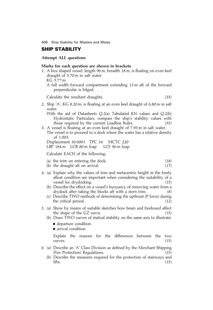
406 Ship Stability for Masters and Mates
SHIP STABILITY
Attempt ALL questions
Marks for each question are shown in brackets1. A box shaped vessel, length 96m, breadth 18m, is ¯oating on even keel
draught of 5.70m in salt water.KG 5.77m.A full width forward compartment extending 13m aft of the forward
perpendicular is bilged.
Calculate the resultant draughts. (35)
2. Ship `A', KG 8.20m, is ¯oating at an even keel draught of 6.80m in saltwater.With the aid of Datasheets Q.2(a) Tabulated KN values and Q.2(b)
Hydrostatic Particulars, compare the ship's stability values withthose required by the current Loadline Rules. (35)
3. A vessel is ¯oating at an even keel draught of 7.93m in salt water.The vessel is to proceed to a dock where the water has a relative density
of 1.003.Displacement 36 000 t TPC 34 MCTC 220LBP 184m LCB 80m foap LCF 96m foap
Calculate EACH of the following:
(a) the trim on entering the dock; (18)(b) the draught aft on arrival. (17)
4. (a) Explain why the values of trim and metacentric height in the freelya¯oat condition are important when considering the suitability of avessel for drydocking. (15)
(b) Describe the effect on a vessel's buoyancy of removing water from adrydock after taking the blocks aft with a stern trim. (8)
(c) Describe TWO methods of determining the upthrust (P force) duringthe critical period. (12)
5. (a) Show by means of suitable sketches how beam and freeboard affectthe shape of the GZ curve. (15)
(b) Draw TWO curves of statical stability on the same axis to illustrate:
. departure condition
. arrival condition
Explain the reasons for the differences between the twocurves. (15)
6. (a) Describe an `A' Class Division as de®ned by the Merchant Shipping(Fire Protection) Regulations. (15)
(b) Describe the measures required for the protection of stairways andlifts. (15)

Specimen examination papers 407
DATASHEET Q.3
(This Datasheet must be returned with your answer book)
MAXIMUM KG (METRES) TO COMPLY WITH MINIMUM STABILITY CRITERIASPECIFIED IN THE CURRENT LOAD LINE RULES
Displacement (t) KG (m)
19 500 7.8519 000 7.9318 500 8.0218 000 8.1017 500 8.1717 000 8.2016 500 8.1916 000 8.1815 500 8.1815 000 8.1914 500 8.2014 000 8.2213 500 8.2413 000 8.2812 500 8.3412 000 8.4211 500 8.5011 000 8.6010 500 8.7110 000 8.859500 9.039000 9.248500 9.488000 9.737500 9.827000 9.626500 9.436000 9.185500 8.845000 8.40
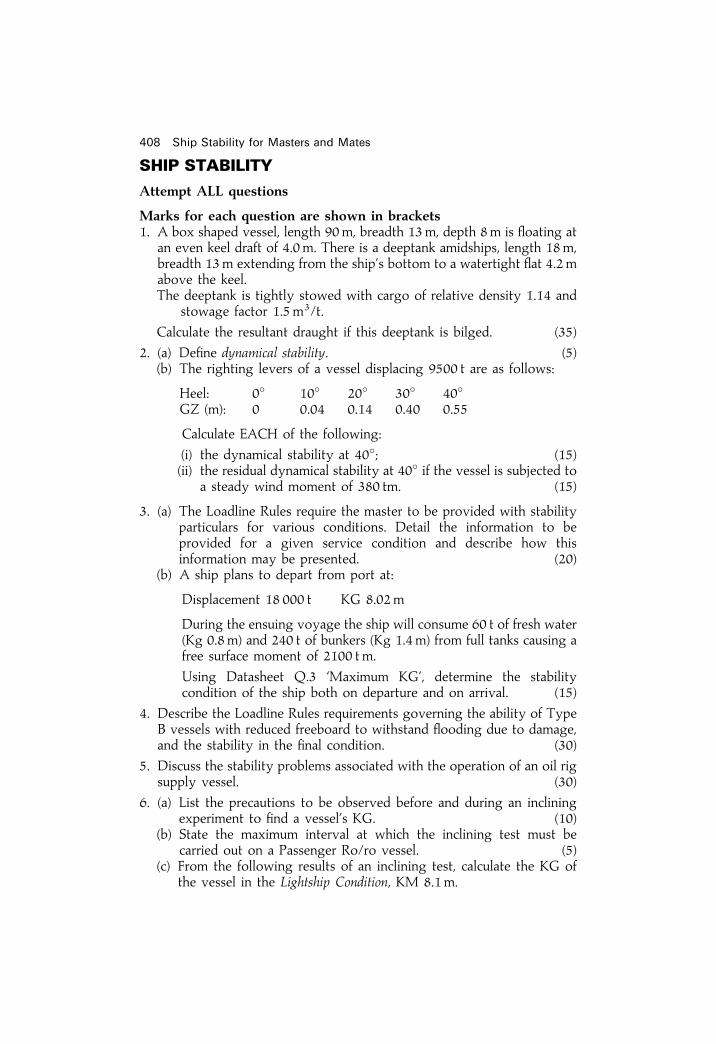
408 Ship Stability for Masters and Mates
SHIP STABILITY
Attempt ALL questions
Marks for each question are shown in brackets1. A box shaped vessel, length 90m, breadth 13m, depth 8m is ¯oating at
an even keel draft of 4.0m. There is a deeptank amidships, length 18m,breadth 13m extending from the ship's bottom to a watertight ¯at 4.2 mabove the keel.The deeptank is tightly stowed with cargo of relative density 1.14 and
stowage factor 1.5m3/t.
Calculate the resultant draught if this deeptank is bilged. (35)
2. (a) De®ne dynamical stability. (5)(b) The righting levers of a vessel displacing 9500 t are as follows:
Heel: 0� 10� 20� 30� 40�GZ (m): 0 0.04 0.14 0.40 0.55
Calculate EACH of the following:
(i) the dynamical stability at 40�; (15)(ii) the residual dynamical stability at 40� if the vessel is subjected to
a steady wind moment of 380 tm. (15)
3. (a) The Loadline Rules require the master to be provided with stabilityparticulars for various conditions. Detail the information to beprovided for a given service condition and describe how thisinformation may be presented. (20)
(b) A ship plans to depart from port at:
Displacement 18 000 t KG 8.02m
During the ensuing voyage the ship will consume 60 t of fresh water(Kg 0.8 m) and 240 t of bunkers (Kg 1.4m) from full tanks causing afree surface moment of 2100 tm.
Using Datasheet Q.3 `Maximum KG', determine the stabilitycondition of the ship both on departure and on arrival. (15)
4. Describe the Loadline Rules requirements governing the ability of TypeB vessels with reduced freeboard to withstand ¯ooding due to damage,and the stability in the ®nal condition. (30)
5. Discuss the stability problems associated with the operation of an oil rigsupply vessel. (30)
6. (a) List the precautions to be observed before and during an incliningexperiment to ®nd a vessel's KG. (10)
(b) State the maximum interval at which the inclining test must becarried out on a Passenger Ro/ro vessel. (5)
(c) From the following results of an inclining test, calculate the KG ofthe vessel in the Lightship Condition, KM 8.1m.

Specimen examination papers 409
Present displacement 5400 t, which includes the following:Inclining weight 25 t, Kg 7.94m.Fuel oil 50 t, Kg 2.30m, FSM 640 t m.The inclining weight is moved 14.0m transversely producing ade¯ection of 27 cm in a plumbline of length 9.0 m. (20)

DATASHEET Q.1
(This Datasheet must be returned with your answer book). Note `foap' denotes for'd of AP
Hydrostatic Particulars `A'
Draught Displacement TPC MCTC KMT KB LCB LCFm t t t m foap foap
SW FW SW FW SW FWRD 1.025 RD 1.000 RD 1.025 RD 1.000 RD 1.025 RD 1.000 m m m m
7.00 14 576 14 220 23.13 22.57 184.6 180.1 8.34 3.64 70.03 67.356.90 14 345 13 996 23.06 22.50 183.0 178.5 8.35 3.58 70.08 67.466.80 14 115 13 771 22.99 22.43 181.4 177.0 8.36 3.53 70.12 67.576.70 13 886 13 548 22.92 22.36 179.9 175.5 8.37 3.48 70.16 67.686.60 13 657 13 324 22.85 22.29 178.3 174.0 8.38 3.43 70.20 67.796.50 13 429 13 102 22.78 22.23 176.8 172.5 8.39 3.38 70.24 67.906.40 13 201 12 879 22.72 22.17 175.3 171.0 8.41 3.33 70.28 68.006.30 12 975 12 658 22.66 22.11 173.9 169.6 8.43 3.28 70.32 68.106.20 12 748 12 437 22.60 22.05 172.5 168.3 8.46 3.22 70.35 68.206.10 12 523 12 217 22.54 21.99 171.1 167.0 8.49 3.17 70.38 68.306.00 12 297 11 997 22.48 21.93 169.8 165.7 8.52 3.11 70.42 68.395.90 12 073 11 778 22.43 21.87 168.5 164.4 8.55 3.06 70.46 68.485.80 11 848 11 559 22.37 21.82 167.3 163.2 8.59 3.01 70.50 68.575.70 11 625 11 342 22.32 21.77 166.1 162.1 8.63 2.95 70.53 68.655.60 11 402 11 124 22.26 21.72 165.0 161.0 8.67 2.90 70.57 68.73

5.50 11 180 10 908 22.21 21.66 163.9 160.0 8.71 2.85 70.60 68.805.40 10 958 10 691 22.15 21.61 162.9 158.9 8.76 2.80 70.64 68.885.30 10 737 10 476 22.10 21.56 161.8 157.9 8.81 2.74 70.68 68.955.20 10 516 10 260 22.05 21.51 160.8 156.9 8.86 2.69 70.72 69.025.10 10 296 10 045 22.00 21.46 159.8 155.9 8.92 2.63 70.75 69.095.00 10 076 9830 21.95 21.41 158.8 154.9 8.98 2.58 70.79 69.164.90 9857 9616 21.90 21.36 157.9 154.0 9.06 2.53 70.82 69.234.80 9638 9403 21.85 21.32 156.9 153.1 9.13 2.48 70.86 69.294.70 9420 9190 21.80 21.27 156.0 152.2 9.22 2.43 70.90 69.354.60 9202 8978 21.75 21.22 155.1 151.3 9.30 2.38 70.93 69.424.50 8985 8766 21.70 21.17 154.2 150.5 9.40 2.32 70.96 69.484.40 8768 8554 21.65 21.12 153.3 149.6 9.49 2.27 71.00 69.554.30 8552 8344 21.60 21.07 152.4 148.7 9.60 2.22 71.04 69.624.20 8336 8133 21.55 21.02 151.5 147.8 9.71 2.17 71.08 69.684.10 8121 7923 21.50 20.97 150.6 146.9 9.83 2.12 71.12 69.744.00 7906 7713 21.45 20.93 149.7 146.0 9.96 2.07 71.15 69.813.90 7692 7505 21.40 20.88 148.7 145.1 10.11 2.01 71.18 69.883.80 7478 7296 21.35 20.83 147.8 144.2 10.25 1.96 71.22 69.943.70 7265 7088 21.30 20.78 146.8 143.3 10.41 1.91 71.25 70.003.60 7052 6880 21.24 20.72 145.9 142.3 10.57 1.86 71.29 70.073.50 6840 6673 21.19 20.67 144.9 141.3 10.76 1.81 71.33 70.14
THESE HYDROSTATIC PARTICULARS HAVE BEEN DEVELOPED WITH THE VESSEL FLOATING ON EVEN KEEL
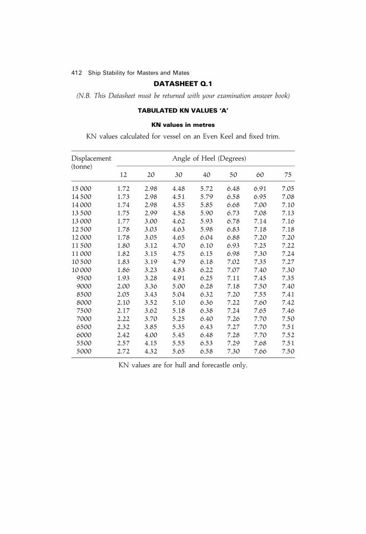
412 Ship Stability for Masters and Mates
DATASHEET Q.1
(N.B. This Datasheet must be returned with your examination answer book)
TABULATED KN VALUES `A'
KN values in metres
KN values calculated for vessel on an Even Keel and ®xed trim.
Displacement Angle of Heel (Degrees)(tonne)
12 20 30 40 50 60 75
15 000 1.72 2.98 4.48 5.72 6.48 6.91 7.0514 500 1.73 2.98 4.51 5.79 6.58 6.95 7.0814 000 1.74 2.98 4.55 5.85 6.68 7.00 7.1013 500 1.75 2.99 4.58 5.90 6.73 7.08 7.1313 000 1.77 3.00 4.62 5.93 6.78 7.14 7.1612 500 1.78 3.03 4.63 5.98 6.83 7.18 7.1812 000 1.78 3.05 4.65 6.04 6.88 7.20 7.2011 500 1.80 3.12 4.70 6.10 6.93 7.25 7.2211 000 1.82 3.15 4.75 6.15 6.98 7.30 7.2410 500 1.83 3.19 4.79 6.18 7.02 7.35 7.2710 000 1.86 3.23 4.83 6.22 7.07 7.40 7.309500 1.93 3.28 4.91 6.25 7.11 7.45 7.359000 2.00 3.36 5.00 6.28 7.18 7.50 7.408500 2.05 3.43 5.04 6.32 7.20 7.55 7.418000 2.10 3.52 5.10 6.36 7.22 7.60 7.427500 2.17 3.62 5.18 6.38 7.24 7.65 7.467000 2.22 3.70 5.25 6.40 7.26 7.70 7.506500 2.32 3.85 5.35 6.43 7.27 7.70 7.516000 2.42 4.00 5.45 6.48 7.28 7.70 7.525500 2.57 4.15 5.55 6.53 7.29 7.68 7.515000 2.72 4.32 5.65 6.58 7.30 7.66 7.50
KN values are for hull and forecastle only.

Specimen examination papers 413
SHIP STABILITY
Attempt ALL questions
Marks for each question are shown in brackets1. Ship `A' has a displacement of 14 000 tonne and a KG of 8.20m.
Using Datasheets Q.1 Tabulated KN Values and Hydrostatic Particulars,determine whether the vessel complies with the stability requirements ofthe current Load Line Rules. (35)
2. A box shaped vessel ¯oating at an even keel in salt water has thefollowing particulars:
Length 75.00m Breadth 18.00m Depth 11.0 mDraft 6.00m KG 6.80m
An empty midship watertight compartment 15.00m long is bilged.
Calculate EACH of the following:
(a) the new draft; (8)(b) the GM in the ¯ooded condition; (12)(c) the righting moment at an angle of 16 degrees. (15)
3. (a) Describe, with the aid of a sketch, the forces that cause a vessel toheel when turning. (12)
(b) A vessel turns in a circle of diameter 200m at a speed of 16 knots.GM 0.78m. BG 0.88m. g� 9.81m/sec2 (Assume 1 knot�1.8532 km/hr).
Calculate the angle of heel due to turning. (18)
4. (a) Describe the hydrostatic, stability and stress data required to besupplied to ships. (30)
(b) A maximum draft forward is sometimes stated in the above datawhen supplied to the ship under the Load Line Rules.
State the reason for this limitation. (5)
5. A vessel with a high deck cargo will experience adverse effects on itsstability due to strong beam winds on lateral windage areas.
With the aid of a sketch, show the minimum stability requirements, withrespect to wind heeling, under current regulations. (35)
6. With regard to the inclining experiment:(a) state its purpose; (5)(b) describe the precautions to be taken before and during the
experiment; (16)(c) list the circumstances when the experiment is required to take
place. (9)

COMMAND ENDORSEMENT (LIMITED EUROPEAN)
Ship Construction and Stability2 hours. Attempt all questions. Marks for each question are shown in brackets.
1. A ship has a light displacement 435 tonnes with KG 3.25m.On board this ship there are 40 tonnes of fuel, water, stores and creweffects at Kg 3.80m with a free surface moment of 35 t m.The single hold is rectangular of length 40m, width 9.4m and depth5.1 m and is to be ®lled with a bulk cargo (stowage factor 1.4 m3/tonne).When ®lled the Kg of the hold is 3.34m.Calculate the GM of the ship in its loaded condition if the loaded KM is4.05m (30)
2. A ship is at displacement 1700 tonnes with draughts 3.20m forward4.05m aft. The following is the appropriate hydrostatic data:
Length BP: 55m TPC: 5.2 MCTC: 22.8Centre of Flotation 2.5m abaft amidship.
Calculate:(a) the drafts forward and aft produced by loading 100 tonnes 40m
forward of the aft perpendicular; (20)(b) from the initial condition, the weight to load 37m forward of the
aft perpendicular to bring the ship to a trim of 0.6 m by the stern.3. Use Worksheet Q.3: Simpli®ed Stability ± Deadweight Moment Curve.
(Ensure that all points plotted on the diagram can be identi®ed in theworking).The load displacement is 1175 tonnes.The ships present condition: displacement 800 tonnes.Deadweight moment 600 t m.Cargo to be loaded: 250 tonnes at Kg 2.8m.
From the above condition:(a) Determine the maximum weight of cargo that can be taken at Kg
4.5m so that stability is adequate. (10)(b) It is anticipated that 30 tonnes of fuel and water at Kg 1.6 m will
be used on passage producing a free surface moment of 100 t m.Determine the maximum weight of cargo that can be loaded atKg 4.5 m so that stability is adequate on arrival at the dischargeport. (20)
4. (a) Explain clearly the meaning of the term `reserve buoyancy'. (15)(b) Describe the items that maintain the integrity of reserve buoyancy
giving a brief indication of any maintenance that may be required.(15)
5. (a) (i) Sketch a typical GZ curve for a stable ship and indicate thefeatures that may be found from it. (15)
(ii) The ship in (a) (i) is now further loaded with deck cargo. Show onthe same curve how the GZ might change due to this. (7)
414 Ship Stability for Masters and Mates

(b) A ship is at a certain draught and displacement.Sketch two GZ curves on the same axes to show this ship in a stiffand a tender condition.
(8)
WORKSHEET Q.3
(N.B. The Worksheet must be returned with your examination answer book. Ensure that allpoints plotted on the diagram can be identi®ed in the working)
COMMAND ENDORSEMENT (EXTENDED EUROPEANS)
Ship Construction and Stability3 hours. Attempt all questions. Marks for each question are shown in brackets.
1. A ship has a light displacement of 2700 tonnes and KG 6.50m. The loaddisplacement of 11 800 tonnes has an associated KM 6.60m. Thefollowing are to be taken on board:
Fuel and FW: 520 tonnes at Kg 0.60mStores: 100 tonnes at Kg 4.50m
A full cargo is then to be loaded in the tween deck at Kg 8.20m andhold at Kg 5.00m to give a sailing GM of 1.00m.
Specimen examination papers 415

Calculate how much of the cargo should be loaded in the:
(i) tween deck;(ii) hold (35)
2. The GZ values of a vessel at a certain displacement are as shown:
Heel (y�) 0 15 30 45 60 75GZ (m) 0 0.27 0.73 0.95 0.61 0.06
KM: 9.00m KG 8.20m
(a) Plot the GZ curve on the graph paper provided. (10)(b) Calculate the area under the curve between 0� and 30� using
Simpson's Rules. (15)(c) Show that the curve satis®es the stability criteria required by the
Load Line Rules 1968. (10)
3. MV Mexna (2) is ¯oating at draughts 6.40m forward and 7.60m aft.Using the hydrostatic data provided (Worksheet Q.3) calculate:
(a) the amount of ballast to load into the forepeak tank (c.g. 60mforward of amid-ships) so that the draught aft is 7.30m; (25)
(b) the ®nal draught forward. (10)
4. Explain with reference to a well labelled sketch, how the effect of freesurface can be considered as a reduction in a vessel's metacentric height.
(35)
5. (a) List the requirements of the Load Line Rules 1968, relating toweathertight doors. (10)
(b) Describe the maintenance and testing of a superstructure door inorder to ensure weathertightness. (20)
6. Illustrate by means of labelled half mid-section sketches each of thefollowing framing systems:
(i) Transverse; (10)(ii) Longitudinal; (10)(iii) Combination. (10)
416 Ship Stability for Masters and Mates

WORKSHEET Q.3 Hydrostatic Curves for Mexna (2)
(N.B. This worksheet must be returned with your answer book)
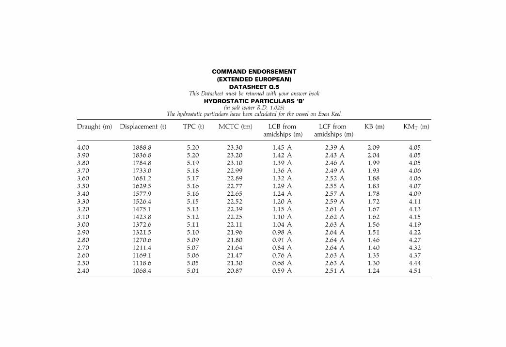
COMMAND ENDORSEMENT
(EXTENDED EUROPEAN)
DATASHEET Q.5This Datasheet must be returned with your answer book
HYDROSTATIC PARTICULARS `B'(in salt water R.D. 1.025)
The hydrostatic particulars have been calculated for the vessel on Even Keel.
Draught (m) Displacement (t) TPC (t) MCTC (tm) LCB from LCF from KB (m) KMT (m)amidships (m) amidships (m)
4.00 1888.8 5.20 23.30 1.45 A 2.39 A 2.09 4.053.90 1836.8 5.20 23.20 1.42 A 2.43 A 2.04 4.053.80 1784.8 5.19 23.10 1.39 A 2.46 A 1.99 4.053.70 1733.0 5.18 22.99 1.36 A 2.49 A 1.93 4.063.60 1681.2 5.17 22.89 1.32 A 2.52 A 1.88 4.063.50 1629.5 5.16 22.77 1.29 A 2.55 A 1.83 4.073.40 1577.9 5.16 22.65 1.24 A 2.57 A 1.78 4.093.30 1526.4 5.15 22.52 1.20 A 2.59 A 1.72 4.113.20 1475.1 5.13 22.39 1.15 A 2.61 A 1.67 4.133.10 1423.8 5.12 22.25 1.10 A 2.62 A 1.62 4.153.00 1372.6 5.11 22.11 1.04 A 2.63 A 1.56 4.192.90 1321.5 5.10 21.96 0.98 A 2.64 A 1.51 4.222.80 1270.6 5.09 21.80 0.91 A 2.64 A 1.46 4.272.70 1211.4 5.07 21.64 0.84 A 2.64 A 1.40 4.322.60 1169.1 5.06 21.47 0.76 A 2.63 A 1.35 4.372.50 1118.6 5.05 21.30 0.68 A 2.63 A 1.30 4.442.40 1068.4 5.01 20.87 0.59 A 2.51 A 1.24 4.51

Specimen examination papers 419
SHIP CONSTRUCTION AND STABILITY
Attempt ALL questions
Marks for each question are shown in brackets1. A vessel of 5200 tonne displacement has a KG of 4.32m and is listed
2.5� to starboard. KM 5.50m (assumed constant).
The following cargo operations take place:
Load: 125 tonne Kg 2.45m and 4.85m to starboard of centreline.Discharge: 280 tonne Kg 3.55m and 1.50m to starboard of centreline.
Calculate EACH of the following:
(a) the resulting angle of list; (25)(b) the angle of list if a slack tank containing salt water and with a fresh
water free surface moment of 900 t m is also considered. (10)
2. A ship is ¯oating at drafts 7.25m forward and 8.45m aft and has to passwith an underkeel clearance of 0.5 m over a bar with a depth of 8.5 m.
The following hydrostatic particulars apply:
Length BP: 180mLCF: 3m aft of amidshipsMCTC: 200After peak tank: Lcg 2m aft of APFore peak tank: Lcg 173m for'd of AP
Calculate EACH of the following:
(a) the amount of water ballast to transfer from the after peak to thefore peak to enable the bar to be crossed with minimum clear-ance; (25)
(b) the ®nal drafts forward and aft. (10)
3. A rectangular shaped vessel of length 50m and breadth 8m ¯oats on aneven keel draft of 1.50m in salt water at a KG of 2.50m.500 tonne is now loaded at Kg 2.20m.
Calculate the vessel's righting moment at 5� heel for the loadedcondition. (35)
4. Explain, with the aid of sketches, how the stability of a vessel is affectedby an increase in EACH of the following:
(a) KG; (15)(b) Freeboard. (20)
5. (a) `When a ship is ¯oating out of design trim, the true mean draft (ordraft at the centre of ¯otation) and not the arithmetic mean draft (ordraft at amidships), must be used with the hydrostatic data in orderto obtain the correct displacement.'
For a ship ¯oating with a trim by the stern and LCF abaft amidships,explain, with reference to a sketch EACH of the following:

420 Ship Stability for Masters and Mates
(i) how the true mean draft is obtained; (10)(ii) why it would be incorrect to use the arithmetic mean draft. (5)
(b) A ship of length BP 56m is ¯oating at draughts 2.70m forward and3.00m aft.Using Hydrostatic Particulars `B' Datasheet Q.5:
Calculate the vessel's true mean draught and displacement. (15)
6. Illustrate EACH of the following with labelled sketches:
(a) the sheer/stringer strake connection at a deck transverse framestation; (10)
(b) a duct keel; (10)(c) the watertight closing (or sealing) arrangements for a deep tank
lid. (10)

Specimen examination papers 421
DATASHEET Q.3
(N.B. This Datasheet must be returned with your examination answer book)
TABULATED KN VALUES `A'
KN values in metres
KN values calculated for vessel on an Even Keel and ®xed trim.
Displacement Angle of Heel (Degrees)(tonne)
12 20 30 40 50 60 75
15 000 1.72 2.98 4.48 5.72 6.48 6.91 7.0514 500 1.73 2.98 4.51 5.79 6.58 6.95 7.0814 000 1.74 2.98 4.55 5.85 6.68 7.00 7.1013 500 1.75 2.99 4.58 5.90 6.73 7.08 7.1313 000 1.77 3.00 4.62 5.93 6.78 7.14 7.1612 500 1.78 3.03 4.63 5.98 6.83 7.18 7.1812 000 1.78 3.05 4.65 6.04 6.88 7.20 7.2011 500 1.80 3.12 4.70 6.10 6.93 7.25 7.2211 000 1.82 3.15 4.75 6.15 6.98 7.30 7.2410 500 1.83 3.19 4.79 6.18 7.02 7.35 7.2710 000 1.86 3.23 4.83 6.22 7.07 7.40 7.309500 1.93 3.28 4.91 6.25 7.11 7.45 7.359000 2.00 3.36 5.00 6.28 7.18 7.50 7.408500 2.05 3.43 5.04 6.32 7.20 7.55 7.418000 2.10 3.52 5.10 6.36 7.22 7.60 7.427500 2.17 3.62 5.18 6.38 7.24 7.65 7.467000 2.22 3.70 5.25 6.40 7.26 7.70 7.506500 2.32 3.85 5.35 6.43 7.27 7.70 7.516000 2.42 4.00 5.45 6.48 7.28 7.70 7.525500 2.57 4.15 5.55 6.53 7.29 7.68 7.515000 2.72 4.32 5.65 6.58 7.30 7.66 7.50
KN values are for hull and forecastle only.

DATASHEET Q.1(e)
(N.B This Datasheet must be returned with your examination answer book). Note: `foap' denotes for'd of AP
Hydrostatic Particulars `A'
Draught Displacement TPC MCTC KMT KB LCB LCFm t t t m foap foap
SW FW SW FW SW FWRD 1.025 RD 1.000 RD 1.025 RD 1.000 RD 1.025 RD 1.000 m m m m
7.00 14 576 14 220 23.13 22.57 184.6 180.1 8.34 3.64 70.03 67.356.90 14 345 13 996 23.06 22.50 183.0 178.5 8.35 3.58 70.08 67.466.80 14 115 13 771 22.99 22.43 181.4 177.0 8.36 3.53 70.12 67.576.70 13 886 13 548 22.92 22.36 179.9 175.5 8.37 3.48 70.16 67.686.60 13 657 13 324 22.85 22.29 178.3 174.0 8.38 3.43 70.20 67.796.50 13 429 13 102 22.78 22.23 176.8 172.5 8.39 3.38 70.24 67.906.40 13 201 12 879 22.72 22.17 175.3 171.0 8.41 3.33 70.28 68.006.30 12 975 12 658 22.66 22.11 173.9 169.6 8.43 3.28 70.32 68.106.20 12 748 12 437 22.60 22.05 172.5 168.3 8.46 3.22 70.35 68.206.10 12 523 12 217 22.54 21.99 171.1 167.0 8.49 3.17 70.38 68.306.00 12 297 11 997 22.48 21.93 169.8 165.7 8.52 3.11 70.42 68.395.90 12 073 11 778 22.43 21.87 168.5 164.4 8.55 3.06 70.46 68.485.80 11 848 11 559 22.37 21.82 167.3 163.2 8.59 3.01 70.50 68.575.70 11 625 11 342 22.32 21.77 166.1 162.1 8.63 2.95 70.53 68.655.60 11 402 11 124 22.26 21.72 165.0 161.0 8.67 2.90 70.57 68.73

5.50 11 180 10 908 22.21 21.66 163.9 160.0 8.71 2.85 70.60 68.805.40 10 958 10 691 22.15 21.61 162.9 158.9 8.76 2.80 70.64 68.885.30 10 737 10 476 22.10 21.56 161.8 157.9 8.81 2.74 70.68 68.955.20 10 516 10 260 22.05 21.51 160.8 156.9 8.86 2.69 70.72 69.025.10 10 296 10 045 22.00 21.46 159.8 155.9 8.92 2.63 70.75 69.095.00 10 076 9830 21.95 21.41 158.8 154.9 8.98 2.58 70.79 69.164.90 9857 9616 21.90 21.36 157.9 154.0 9.06 2.53 70.82 69.234.80 9638 9403 21.85 21.32 156.9 153.1 9.13 2.48 70.86 69.294.70 9420 9190 21.80 21.27 156.0 152.2 9.22 2.43 70.90 69.354.60 9202 8978 21.75 21.22 155.1 151.3 9.30 2.38 70.93 69.424.50 8985 8766 21.70 21.17 154.2 150.5 9.40 2.32 70.96 69.484.40 8768 8554 21.65 21.12 153.3 149.6 9.49 2.27 71.00 69.554.30 8552 8344 21.60 21.07 152.4 148.7 9.60 2.22 71.04 69.624.20 8336 8133 21.55 21.02 151.5 147.8 9.71 2.17 71.08 69.684.10 8121 7923 21.50 20.97 150.6 146.9 9.83 2.12 71.12 69.744.00 7906 7713 21.45 20.93 149.7 146.0 9.96 2.07 71.15 69.813.90 7692 7505 21.40 20.88 148.7 145.1 10.11 2.01 71.18 69.883.80 7478 7296 21.35 20.83 147.8 144.2 10.25 1.96 71.22 69.943.70 7265 7088 21.30 20.78 146.8 143.3 10.41 1.91 71.25 70.003.60 7052 6880 21.24 20.72 145.9 142.3 10.57 1.86 71.29 70.073.50 6840 6673 21.19 20.67 144.9 141.3 10.76 1.81 71.33 70.14
THESE HYDROSTATIC PARTICULARS HAVE BEEN DEVELOPED WITH THE VESSEL FLOATING ON EVEN KEEL

424 Ship Stability for Masters and Mates
SHIP CONSTRUCTION AND STABILITYAttempt ALL questions
Marks for each question are shown in brackets1. All parts of question 1 carry equal marks.
(a) De®ne Transverse Metacentre.(b) De®ne Statutory Freeboard.(c) State the meaning of watertight as given in the Load Line Rules 1968.(d) A ship of displacement 15 000 t is heeled 3�. Given KG 8.46m and
KM 9.36m determine the Righting Moment.(e) Use Datasheet Q.1(e).
The ship, length 145m, is ¯oating in fresh water at drafts 4.30mForward and 6.30m Aft. Determine the ship's displacement. (35)
2. Use Datasheet Q.1(e).The ship, at displacement 6950 t, KG 7.80m loads the following:
2800 t at Kg 3.79m3400 t at Kg 6.86m900 t at Kg 8.89m500 t at Kg 10.30m
On passage it is anticipated that 950 t of fuel and fresh water will beused from Kg 2.85m producing a free surface moment of 414 t m.
Calculate the GM on arrival. (30)
3. Use Datasheets Q.1(e) and Q.3.The ship is at displacement 11 750 t, KG 8.00m.
(a) Draw the GZ curve for the ship in this condition. (20)(b) Using the curve drawn in Q.3(a), estimate EACH of the following:
(i) the angle of vanishing stability.(ii) the angle of deck edge immersion.(iii) the maximum GZ and the angle at which it occurs. (10)
4. Use Hydrostatic Datasheet Q.1(e).The ship, length b.p. 140m, is at drafts 6.10m Forward and 6.50m Aft.100 t of ballast, already on board, is to be moved 85m forward.
(a) Calculate the position, with reference to amidship, at which 227 t ofcargo should be loaded so that the ship ®nishes on an even keel.(20)
(b) Determine the ®nal draught. (10)
5. A ship of displacement 9500 t ¯oats upright in still water with KG8.84m and KM 9.96m.On passage containers of weight 65 tonne are lost overside from aposition Kg 12.0 m, 10.5 m to port of the centreline.
Calculate the list to be expected giving the direction. (25)
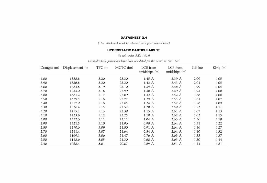
DATASHEET Q.4
(This Worksheet must be returned with your answer book)
HYDROSTATIC PARTICULARS `B'
(in salt water R.D. 1.025)
The hydrostatic particulars have been calculated for the vessel on Even Keel.
Draught (m) Displacement (t) TPC (t) MCTC (tm) LCB from LCF from KB (m) KMT (m)amidships (m) amidships (m)
4.00 1888.8 5.20 23.30 1.45 A 2.39 A 2.09 4.053.90 1836.8 5.20 23.20 1.42 A 2.43 A 2.04 4.053.80 1784.8 5.19 23.10 1.39 A 2.46 A 1.99 4.053.70 1733.0 5.18 22.99 1.36 A 2.49 A 1.93 4.063.60 1681.2 5.17 22.89 1.32 A 2.52 A 1.88 4.063.50 1629.5 5.16 22.77 1.29 A 2.55 A 1.83 4.073.40 1577.9 5.16 22.65 1.24 A 2.57 A 1.78 4.093.30 1526.4 5.15 22.52 1.20 A 2.59 A 1.72 4.113.20 1475.1 5.13 22.39 1.15 A 2.61 A 1.67 4.133.10 1423.8 5.12 22.25 1.10 A 2.62 A 1.62 4.153.00 1372.6 5.11 22.11 1.04 A 2.63 A 1.56 4.192.90 1321.5 5.10 21.96 0.98 A 2.64 A 1.51 4.222.80 1270.6 5.09 21.80 0.91 A 2.64 A 1.46 4.272.70 1211.4 5.07 21.64 0.84 A 2.64 A 1.40 4.322.60 1169.1 5.06 21.47 0.76 A 2.63 A 1.35 4.372.50 1118.6 5.05 21.30 0.68 A 2.63 A 1.30 4.442.40 1068.4 5.01 20.87 0.59 A 2.51 A 1.24 4.51

426 Ship Stability for Masters and Mates
GENERAL SHIP KNOWLEDGEAttempt ALL questions
Marks for each question are shown in brackets1. A combustible gas indicator (explosimeter) is used to check the atmo-
sphere of a cargo oil tank.
(a) Describe how the instrument is used. (5)(b) State the information given by the instrument. (5)(c) State THREE circumstances where a zero reading may give a false
idea of the cargo tank atmosphere. (15)
2. (a) De®ne TPC and explain its use. (5)(b) Explain why TPC changes with the draft of a conventional ship.(10)(c) Explain how the TPC in fresh water may be found. (5)
3. A ship has been laid up for four months. Before the ship re-entersservice, a survey is necessary. The fore-peak tank which is empty,requires inspection.State the safety precautions that should be taken. (25)
4. A ship has a load draft of 3.80m in seawater.The present mean draft in seawater is 3.30m and KG is 3.65m.40 tonnes of bunkers are then loaded at Kg 0.50m giving a free surfacemoment of 150 tonnesmetres. The loading plan requires 100 tonnes ofcargo to be loaded in the hold at Kg. 2.50m and the remainder of thecargo to be loaded on deck at Kg 5.00m.Using the Worksheet Q.4, calulate EACH of the following:
(a) the weight of deck cargo; (10)(b) the load KG; (10)(c) the metacentric height when fully loaded. (10)
5. A ship is upright. A 10 tonne container is then lifted with the ship's ownderrick from the centre-line of the lower hold and is re-stowed on theport side of the weather deck.Explain, with suitable sketches, the movement of the ship's centre ofgravity when the container:
(a) is ®rst lifted; (10)(b) is swung to the port side; (10)(c) is landed on the weather deck. (10)
6. Describe FIVE main hazards which can occur with the carriage of solidbulk cargoes. (20)

Specimen examination papers 427
OPERATIONAL SAFETYAttempt ALL questions
Marks for each question are shown in brackets1. (a) A vessel on even keel is at anchor outside a port in SW of RD 1.025
at a Summer Load draught of 10.24m.TPC 18 (constant); Summer Load displacement 13 176 t.Calculate the quantity of cargo to discharge into barges in order thatthe vessel can pass over a bar at the river entrance (RD 1.025) withan under keel clearance of 1.5 m. Depth of water available at thebar� 9.25m. (10)
(b) Calculate the FWA of the vessel mentioned in Q.1(a). (7)(c) Explain why, when loading a vessel, it is necessary to know the
Dock Water density. (8)
2. A vessel is initially displacing 6650 t.
KG 8.40m; KM 8.90m (constant).
A 38 t weight is to be discharged from a position on the centreline Kg5.2 m using the vessel's own derrick. The derrick head is 32m above thekeel.Calculate the vessel's GM value when:
(a) the weight is lifted just clear of the initial stowage position; (15)(b) the weight is ®nally discharged ashore. (10)
3. (a) Explain the formation of EACH of the following:(i) ship's sweat; (6)(ii) cargo sweat. (6)
(b) List FIVE reasons for ventilating the holds of a general cargovessel. (5)
(c) (i) List SIX hygroscopic cargoes. (6)(ii) List TWO non-hygroscopic cargoes. (2)
4. (a) State the meaning of EACH of the following abbreviations:(i) FLT; (1)(ii) ISO. (2)
(b) List the methods by which cargo can be secured onto pallets. (5)(c) State the advantages and disadvantages of unitising cargo. (17)
5. (a) With respect to the carriage of bulk or packaged Dangerous Goods,state the meaning of EACH of the following abbreviations:(i) EmS No; (1)(ii) MFAG No; (1)(iii) UN No. (2)
(b) List the main headings found under an EmS entry. (10)(c) Detail the symptoms resulting from exposure to increasing con-
centrations of Benzene. (3)(d) List the principal sources of information when carrying any type of
dangerous cargo. (8)

428 Ship Stability for Masters and Mates
6. (a) De®ne EACH of the following terms:
(i) upper ¯ammable limit (UFL); (3)(ii) lower ¯ammable limit (LFL); (3)(iii) ¯ammable range (also referred to as `explosive range'). (3)
(b) Draw a diagram which shows the relationship between EACH of theterms in Q.6(a). (6)
(c) State the limitations when using a combustible gas indicator(explosimeter). (10)

Appendix VII
Revision one-linersThe following are sixty-®ve one-line questions acting as an aid toexamination preparation. They are similar in effect to using mentalarithmetic when preparing for a mathematics exam. Elements of questionsmay well appear in the written papers or in the oral exams. Good luck.
1. What is another name for the KG?2. What is a hydrometer used for?3. If the angle of heel is less than 10 degrees, what is the equation for GZ?4. What are the formulae for TPC and MCTC for a ship in salt water?5. Give two formulae for the Metacentre, KM.6. How may Free Surface Effects be reduced on a ship?7. What is another name for KB?8. List four requirements before an Inclining Experiment can take place.9. With the aid of a sketch, de®ne LOA and LBP.10. What are Cross Curves of Stability used for?11. What is the longitudinal centre of a waterplane called?12. Adding a weight to a ship usually causes two changes. What are these
changes?13. What is Simpson's First Rule for a parabolic shape with seven equally
spaced ordinates?14. What is KB for (a) box-shaped vessel and (b) triangular-shaped vessel?15. What are Hydrostatic Curves used for onboard a ship?16. Using sketches, de®ne the Block, the Waterplane and Midship form
coef®cients.17. Sketch a Statical Stability curve and label six important points on it.18. What are the minimum values allowed by D.Tp. for GZ and for
transverse GM?19. List three ways in which a ship's end drafts may be changed.20. GM is 0.45m. Radius of gyration is 7m. Estimate the natural rolling
period in seconds.21. What is a Deadweight Scale used for?

22. What is the formula for Bending Stress in terms of M, I and y?23. Sketch a set of Hydrostatic Curves.24. List three characteristics of an Angle of Loll.25. De®ne (a) a moment and (b) a moment of inertia.26. Sketch the ®rst three curves for a set of ship's Strength Curves.27. What is the `theory of parallel axis' formula?28. What are the effects on a Statical Stability curve for increased Breadth
and increased Freeboard?29. Sketch a Metacentric Diagram for a box-shaped vessel and a triangular-
shaped vessel.30. Block coef®cient is 0.715. Midship coef®cient is 0.988. Calculate
Prismatic coef®cient.31. Describe the use of Simpson's Third Rule.32. What is the wall-sided formula for GZ?33. De®ne `permeability'. Give two examples relating to contents in a hold
or tank.34. Give the equations for BM, box-shaped vessels and triangular-shaped
vessels?35. List three characteristics of an Angle of List.36. Sketch the Shear force and Bending Moment curves. Show their inter-
relation.37. For a curve of seven equally spaced ordinates give Simpson's Second
Rule.38. What is the formula for pressure of water on a lockgate situation?39. When a weight is lifted from a jetty by a ship's derrick whereabouts
does its CG act?40. Sketch a set of Freeboard Marks and label dimensions as speci®ed by
D.Tp.41. Sketch a Displacement curve.42. What is Morrish's formula for VCB?43. For an inclining experiment how is tangent of the angle of list
obtained?44. What do `a moment of statical stability' and `dynamical stability' mean?45. Show the range of stability on an S/S curve having a very small initial
negative GM.46. Breadth is 45m. Draft is 15m. What is the increase in draft at a list of 2
degrees?47. What is the formula for loss of GM due to free surface effects in a slack
tank?48. For what purpose is the Inclining Experiment made on ships?49. What is the `true mean draft' on a ship?50. When drydocking a ship there is a virtual loss in GM. Give two
formulae for this loss.51. With Simpson's Rules, give formulae for M of I about (a) Amidships
and (b) Centre line.
430 Ship Stability for Masters and Mates

52. Discuss the components involved for estimating an angle of heel whilstturning a ship.
53. What is a `stiff ship' and a `tender ship'. Give typical GM values.54. With the Lost Buoyancy method, how does VCG change, after bilging
has occurred?55. Sketch a Deadweight Moment curve and label the important parts.56. Sketch a Bending stress diagram for a vessel that is in a Sagging
condition.57. What are `Bonjean curves' and for what purpose are they used?58. De®ne `Ship Squat' and `blockage factor'.59. Draw the line diagram for Murray's method for maximum Bending
Moment.60. What is the formula for shear stress for an H-girder?61. What happens to cause a vessel to be in Unstable equilibrium?62. What causes Hogging in a vessel?63. Which letters signify the Metacentric Height?64. Give typical Cb values for fully loaded VLCC, general cargo ships and
passenger liners.65. What happens when a ship passes from one density of water to another
water density?
Revision one-liners 431
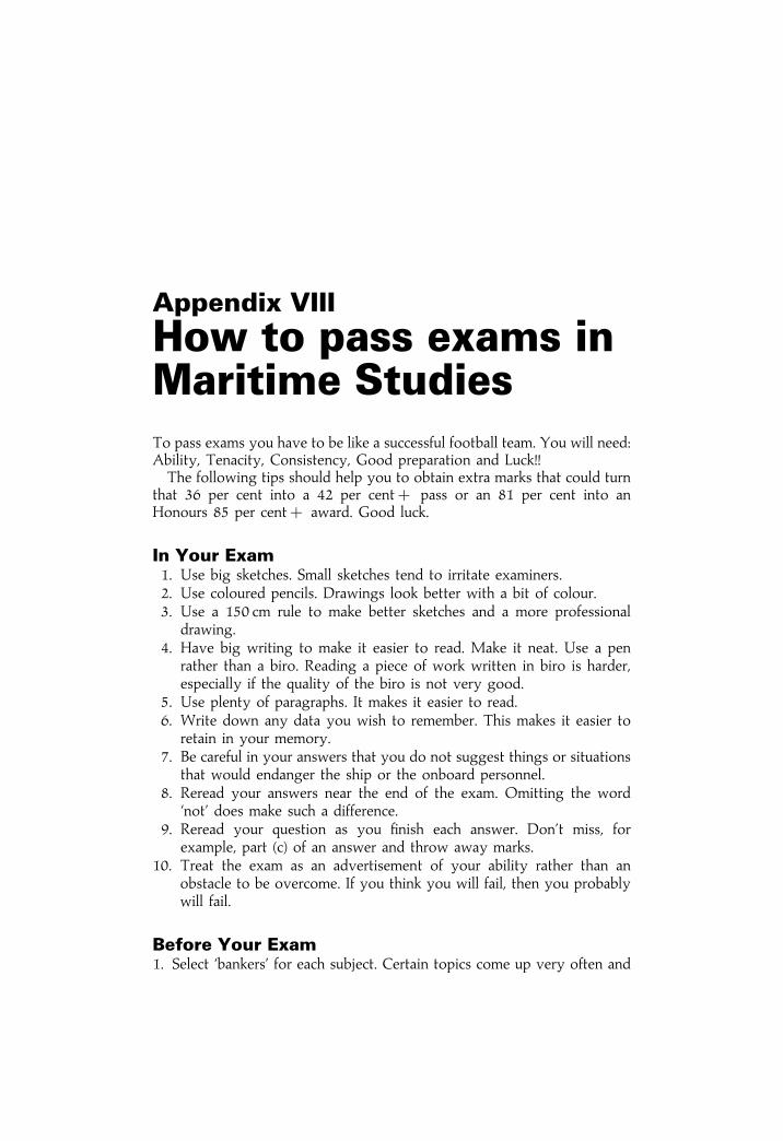
Appendix VIII
How to pass exams inMaritime StudiesTo pass exams you have to be like a successful football team. You will need:Ability, Tenacity, Consistency, Good preparation and Luck!!The following tips should help you to obtain extra marks that could turn
that 36 per cent into a 42 per cent� pass or an 81 per cent into anHonours 85 per cent� award. Good luck.
In Your Exam1. Use big sketches. Small sketches tend to irritate examiners.2. Use coloured pencils. Drawings look better with a bit of colour.3. Use a 150 cm rule to make better sketches and a more professional
drawing.4. Have big writing to make it easier to read. Make it neat. Use a pen
rather than a biro. Reading a piece of work written in biro is harder,especially if the quality of the biro is not very good.
5. Use plenty of paragraphs. It makes it easier to read.6. Write down any data you wish to remember. This makes it easier to
retain in your memory.7. Be careful in your answers that you do not suggest things or situations
that would endanger the ship or the onboard personnel.8. Reread your answers near the end of the exam. Omitting the word
`not' does make such a difference.9. Reread your question as you ®nish each answer. Don't miss, for
example, part (c) of an answer and throw away marks.10. Treat the exam as an advertisement of your ability rather than an
obstacle to be overcome. If you think you will fail, then you probablywill fail.
Before Your Exam1. Select `bankers' for each subject. Certain topics come up very often and

these you will have fully understood. Bank on these appearing on theexam paper.
2. Don't swat 100 per cent of your course notes. Omit about 10 per centand concentrate on the 90 per cent. In that 10 per cent will be sometopics you will never be able to understand fully.
3. Work through past exam papers in order to gauge the standard and thetime factor to complete the required solution. Complete and hand inevery set coursework assignment.
4. Write all formulae discussed in each subject on pages at the rear of yournotes.
5. In your notes circle each formula in a red outline or use a highlight pen.In this way they will stand out from the rest of your notes. Rememberformulae are like spanners. Some you will use more than others but allcan be used to solve a problem.
6. Underline in red important key phrases or words. Examiners will belooking for these in your answers. Oblige them and obtain the marks.
7. Revise each subject in carefully planned sequence so as not to be rustyon a set of notes that you have not read for some time whilst you havebeen sitting other exams.
8. Be aggressive in your mental approach to do your best. If you haveprepared well there will be a less nervous approach and, like the footballteam, you will gain your goal.
How to pass exams in Maritime Studies 433

Appendix IX
Draft SurveysWhen a ship loads up at a port, departs from this port and travels toanother port, a Draft Survey is carried out. This is to check that the cargodeadweight or `constant' is satisfactory for the shipowner at the port ofarrival.It is virtually a check on the amount of cargo that left the ®rst port
against that arriving at the second port. This Draft Survey may be carriedout by a Master, a Chief Engineer or a Naval Architect.Prior to starting on a Draft Survey the vessel should be in upright
condition and on even keel if possible. If not on even keel then certainlywithin 1 per cent of her LBP would be advantageous.When the ship arrives in port ready for this Draft Survey, there are
several items of information that have to be known by, say, the NavalArchitect. They include:
LBP and Cb relative to the ship's waterline or actual loaded condition.Lightweight.Density of the water in which the vessel is ¯oating.Draft readings port and starboard at the stern, midships and at the bow.Distance from aft perp to Aft draft marks.Distance from amidships to midship draft marks.Distance from forward perp to forward draft marks.Distance of LCF from amidships.Cargo deadweight or `constant', for example, say 10 766 t.
Using above data the Naval Architect will modify the actual draft readingsto what they would be at AP, amidships and FP. These values are then usedto determine the mean draft at the position of the ship's LCF (see chapter onTrim).To take into account any Hog or Sag a `mean of means' formula is used.
Suppose the drafts at the AP, amidships and FP were 8.994m, 8.797m,8.517m and LCF was 0.37m forward of amidships with an LBP of 143.5 m.Then the mean of means draft is:

Means of means draft � �dAP��6� dAM� � dFP�=8� �8:994� �6� 8:797� � 8:517�=8
Thus, mean of means draft � 8:787m
When corrected for LCF position, the mean draft is 8.786m:The Naval Architect uses this draft of 8.786m on the ship's Hydrostatic
Curves or tabulated data to obtain a ®rst estimate of the displacement andTPC. These are of course for salt water density of 1.025 t/m3. Assume thisdisplacement was 17 622 t and the TPC was 25.86 t. The Naval Architectcan now evaluate the Fresh Water Allowance and proceed to make acorrection for density.
FWA � W=�4� TPC� � 17 662=�4� 25:86�FWA � 171mm
The density correction is then made (see chapter on Density correction).Assume the water was of 1.019 t/m3. Consequently this correction wouldbe minus 0.041m.
Thus, the final true draft would be 8.786ÿ 0:041 � 8.745m:
Interpolating once more the Hydrostatic data the ®nal Displacement at thetime of the Draft Survey is obtained. Pressume this ®nal Displacement is17 537 tonnes.From this ®gure must be deducted the Lightweight and all other
deadweight items (except the `constant' or Cargo deadweight). Assumethis Lightweight was 5675 t and the residual dwt of oil, fresh water, stores,crew and effects, water ballast etc. was 1112 t. This residual dwt wouldhave been estimated after all tanks had been sounded and all compartmentsbeen checked for contents. Then the ®nal Cargo dwt or `constant' is:
Cargo deadweight � 17 537ÿ 5675ÿ 1112 � 10 750 tonnes
This compares favourably with the Cargo dwt given at the port ofdeparture, that is 10 766 tonnes, a difference of 0.15 per cent. In a perfectworld the Cargo dwt at the arrival port would have been `constant' at10 766 t. However, ships are not built to this degree of accuracy andmeasurement to this standard is very hard to achieve.
Summary:Corrections have been made for:
Draft mark positions. Trim and LCF position.Hog or sag. Density of water.
True mean draft is 8.745m True displacement is 17 537 t
Cargo deadweight or `constant' is 10 750 t �ÿ0:15 per cent�
Draft Surveys 435

A well-conducted survey is capable of achieving an absolute accuracy ofwithin plus or minus 0.50 per cent of the Cargo dwt. This is as good, if notbetter, as other systems of direct weighing.Error can creep in over the years because of the ship's reported
Lightweight. This is due to the ship herself gaining about 0.50 per centLightweight each year in service. Hence over a period of ten years this shipwould have gained about 280 tonnes since her maiden voyage.Lightweight will also alter slightly depending on the position of the
anchors and cables. Obviously, with anchors fully housed the Lightweightwill be more. Adjustment may have to be made but it is better if at bothports the anchors are fully housed.Error can also be made if the draft readings were taken in a tidal current.
The speed of the tide would cause the ship to sink slightly in the water(squat effects) and so give draft readings that were too high in value. Onereported instance of this occurring resulted in a cargo reduction of over300 t. Initially this was put down to excessive pilfering until further checksdiscovered that drafts had been taken in moving water. At departure andarrival ports draft readings must be read when water speed is zero.One suggestion for improving accuracy of measurement is to have draft
marks also at 1/4L and 3/4L from aft. In other words at stations 2.5 and 7.5.They would reduce errors where there is an appreciable hog or sag at thetime of the Draft Survey.
436 Ship Stability for Masters and Mates
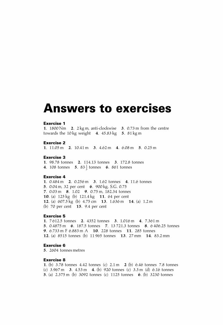
Answers to exercisesExercise 11. 1800Nm 2. 2 kgm, anti-clockwise 3. 0.73 m from the centretowards the 10 kg weight 4. 45.83 kg 5. 81 kgm
Exercise 21. 11.05m 2. 10.41 m 3. 4.62 m 4. 6.08 m 5. 0.25m
Exercise 31. 98.78 tonnes 2. 114.13 tonnes 3. 172.8 tonnes4. 108 tonnes 5. 83 1
3 tonnes 6. 861 tonnes
Exercise 41. 0.484m 2. 0.256m 3. 1.62 tonnes 4. 11.6 tonnes5. 0.04m, 32 per cent 6. 900 kg, S.G. 0.757. 0.03m 8. 1.02 9. 0.75 m, 182.34 tonnes10. (a) 125 kg (b) 121.4 kg 11. 64 per cent12. (a) 607.5 kg (b) 4.75 cm 13. 1.636m 14. (a) 1.2 m(b) 70 per cent 15. 9.4 per cent
Exercise 51. 7 612.5 tonnes 2. 4352 tonnes 3. 1.016m 4. 7.361m5. 0.4875m 6. 187.5 tonnes 7. 13 721.3 tonnes 8. 6 406.25 tonnes9. 6.733m F 6.883m A 10. 228 tonnes 11. 285 tonnes12. (a) 8515 tonnes (b) 11 965 tonnes 13. 27 mm 14. 83.2 mm
Exercise 65. 2604 tonnesmetres
Exercise 81. (b) 3.78 tonnes 4.42 tonnes (c) 2.1 m 2 (b) 6.46 tonnes 7.8 tonnes(c) 3.967m 3. 4.53m 4. (b) 920 tonnes (c) 3.3 m (d) 6.16 tonnes5. (a) 2.375m (b) 3092 tonnes (c) 1125 tonnes 6. (b) 3230 tonnes

(c) 1.625m 7. (b) 725 tonnes (c) 4.48m (d) 5 tonnes8. (b) 5150 tonnes 4.06m (c) 5.17m
Exercise 91. (b) 12.3 tonnes 2. (b) 8302.5 tonnes 3. 12 681.3 tonnes4. 221 tonnes 5. 180 tonnes 6. 95 7. 53
Exercise 101. (a) 508m2 (b) 5.2 tonnes (c) 0.8 m aft of amidships 2. (a) 488m2
(b) 5 tonnes (c) 0.865 (d) 0.86m aft of amidships 3. (a) 122mm(b) 43.4 m from forward 4. (a) 30 476.7 tonnes (b) 371.4mm (c) 15.6 m5. 5062.5 tonnes 6. (a) 978.3 m2 (b) 15.25 cm(c) 2.03m aft of amidships 7. (a) 999334 tonnes (b) 97.44mm (c) 4.33m
8. (a) 671.83 m2 (b) 1.57m aft of amidships9. 12.125m2 10. 101m2 11. (a) 781.67m3 (b) 8.01 tonnes12. (a) 2 893.33m3 or 2965.6 tonnes (b) 3 m
Exercise 111. 2.84m 2. 3.03m 3. 3.85 m 4. 5.44 m 5. 0.063m6. 1466.67 tonnes 7. 1525 tonnes8. 7031.3 tonnes in L.H and 2568.7 tonnes in T.D. 9. 1.2 m 10. 1.3 m11. 55 tonnes 12. 286.3 tonnes 13. 1929.67 tonnes
Exercise 121. 5 m 2. (a) 1.28m (b) 4.56m 3. (a) 1.78m (b) 3m4. No. Unstable when upright. 5. (a) 6.2 m, 13.78m (b) 4.9m6. (a) 10.6 m, 5.13m (b) 4.9m at 4.9m draft 7. (a) 6.31m, 4.11m(b) 4.08m 8. (b) GM is �1.8m, vessel is in stable equilibrium(c) GM is zero, KG� KM, so ship is in neutral equilibrium
Exercise 131. 6� 030 to starboard 2. 4.2 m3. 216.5 tonnes to port and 183.5 tonnes to starboard 4. 9� 3005. 5.458m 6. 12� 570 7. 91 9 tonnes8. 282.75 tonnes to port, 217.25 tonnes to starboard9. 8.52m to port GM� 0.864m 10. 14� 40 to port 11. 13� 24012. 50 tonnes 13. 3.8�
Exercise 141. 674.5 tonnesmetres 2. 7.773m 3. 546.2 m4. 6.027m, 2000 tonnes metres 5. (a) 83.43 tonnesmetres(b) 404.4 tonnesmetres 6. (a) 261.6 tonnesmetres(b) 2647 tonnesmetres 7. (a) 139.5 tonnesmetres(b) 1366 tonnesmetres 8. 0.522m9. Angle of Loll is 14.96�, KM is 2.67m, GM is ÿ0:05m
438 Answers to exercises

Exercise 151. 218.4 tonnes in No. 1 and 131.6 tonnes in No. 4. 2. 176.92 tonnes3. 5.152m F 5.342m A 4. 6.162m F 6.726m A5. 668.4 tonnes from No. 1 and 1331.6 tonnes from No. 4.6. 266.7 tonnes 7. 24.4 cm 8. 380 tonnes, 6.785m F9. 42.9 tonnes in No. 1, and 457.1 in No. 4 GM� 0.79m10. 402.1 tonnes from No. 1 and 47.9 tonnes from No. 411. 3.118m F 4.340m A 12. 5.50 m F 5.56m A13. 5.679m F 5.901m A 14. 4 metres aft 15. 3.78 metres aft16. 4.44 metres aft 17. 55.556 metres forward18. 276.75 tonnes; 13.6 metres forward 19. 300 tonnes; 6.3 m20. 200 tonnes; 7.6 m 21. 405 tonnes in No. 1 and 195 tonnes in No. 422. 214.3 tonnes 23. 215.4 tonnes; 5.96m F 24. 200 metres25. 240 metres 26. Draft aft is 8.23m. Draft forward is 7.79m. Dwt is9195 t. Trim by the stern is 0.44m
Exercise 161. GM � 2m, Range 0N84:5�, Max. GZ � 2:5m at 43.5� heel.2. GM � 4:8m, Max. Moment � 67 860 tonnesmetres at 42.25� heel,Range 0N81:5� 3. GM � 3:07m, Max. GZ � 2:43m at 41� heel,Range 0±76�, Moment at 10� � 16 055 tonnes metres. Moment at40� � 59 774 tonnes metres 4. Moment at 10� � 16 625 tonnesmetres,GM� 2m, Max. GZ� 2.3m at 42� heel, Range 0±82�5. GM � 3:4m. Range 0±89.5�, Max. GZ� 1.93m at 42� heel.6. 6.61m 7. 8.37m 8. 25.86 m forward9. 39 600 tonnes; 513 tonnes metres; 40.5 tonnes; 9.15m10. 3.15 m F 4.53m A 11. (a) 0±95�, (b) 95�, (c) 3.18m at 47.5�12. (a) 0±75�, (b) 75�, (c) 2.15m at 40� 13. 1.60 m 40�, 12�, 72.5�14. 1.43 m, 39.5�, 44 000 tonnes metres, 70�
Exercise 171. 1.19m 2. 1.06m 3. 0.64 m 4. 7 m 5. 4.62 m
Exercise 181. 1.545m 2. 6.15 tonnes/m2 3. 7.175 tonnes/m2, 1,435 tonnes4. 6.15 tonnes/m2, 55.35 tonnes 5. 9 tonnes/m2, 900 tonnes6. 6.15 tonnes/m2, 147.6 tonnes 7. 1 tonne8. 386.76 tonnes on side with density 1010 kg/m3
9. 439.4 tonnes on side with density 1016 kg/m3 10. 3075 tonnes11. 128.13 tonnes
Exercise 191. Transfer 41.94 tonnes from starboard to port, and 135 tonnes fromforward to aft.2. Transfer 125 tonnes from forward to aft, and 61.25 tonnes from port tostarboard. Final distribution: No. 1 Port 75 tonnes, No. 1 starboard
Answers to exercises 439
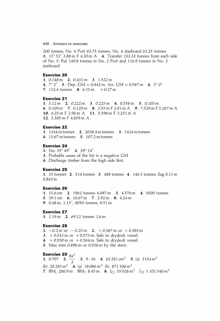
��� ������� � � �� � ���� ������� � � ��� ��� � ���� ������� ��� ��� ���� � ���� � � � ����� ����� ������ � �� ���� ������ � � ��� �� � ������ �� � � �� � ��� ��� ������ �� � ���� ��� �
�������� �� ����� � ����� � ������ �� �� � !�" #$� ������ � #$� ����� � �� ��� ���� ������ � ���� � ����
�������� �� ���� � ����� � ����� � ����� � ������ ��� � � ��� � � ��� � � ���� � ��� � � ����� �� ��� � � � �� � �� �� �� � ����� ��� ����� � ��� � �
�������� ��� ����� ������ � ����� � ������ � ����� ������� ����� ������ � ���� � ������
�������� ��� �% ��� � � � � � ���� � ����&� ����� �� ��� &��� �� � ��'���(� #$� !����� '� ����� � �� ��� ��'� ���� ) ��
�������� ��� �� ������ � ��� ������ � ��� ������ � ���� ������ *�' ���������
�������� � � ��� �� � � �� ������ ����� � ����� � ���� ������� � � �� � ����� � � � � � ��� � ����� ����� ���� ������� ����
�������� ��� �� � � � �� ������ �� �
�������� ��� ����� � � ����� � � ����� � � ������ � ����� � � ����� *��� �� � +���, (����&� � ����� � � ����� *��� �� � +���, (����&� $�- � �� �� �� � � ��� �+ ��� ��� �
�������� ��� ���� �
���
�� � �� � �� ��� ��� � .�/ ������
.�/ �� ����� � .�/ �� ����� .�/ ��� �����
� 0$1 ��� � 0$� ���� � 231 �� ����� 23� � ��� �����
��� ������� ����� ���

9. ICL 20 267m4 ICF 795 417m4 10. ICL 13 227m
4 ICF 396 187m4
Exercise 301. 658.8 tonnes 4.74m 2. 17.17m 3. 313.9 tonnes 2.88m4. 309.1 tonnes 1.74m 5. 5.22m
Exercise 311. (a) 366.5 m (b) 0.100 (c) 0.65m (d) 0.85m2. (a) W of I is 418m > 350m (c) 9.05 kt 3. 10.56 kt
Exercise 321. 4� 340 2. 6� 40 3. 5� 440 4. 6.8� to starboard
Exercise 331. 20.05 s 2. 15.6 s 3. 15.87 s 4. TR is 28.2 s ± rather a `tender ship'
Exercise 341. 3.6� 2, 11.57� 3. 5.7� 4. 4.9� 5. 8�
Exercise 361. Passenger liner (0.78m) and general cargo ship (0.66m)
Exercise 371. 4.1 m F 8.2 m A 2. 2.44 m F 4.39m A3. Draft aft is 6.91m, draft forward is 6.87m
Exercise 381. 14� 330 2. 13� 40 3. 9� 520 4. 5� 350
Exercise 401. Max. BM 2.425 tonnesm at 5.8 m from A2. (a) Max. BM 29.2 tonnes m between the positions of the twomasses. (b) At 13 L from L.H. side SF� 4.87 tonnes BM� 24.34 tonnes m.At 1
3 L from R.H. side SF� 0.13 tonnes, BM� 28.65 tonnesm
Exercise 431. Max. SF� �40 tonnes Max. BM� � 145.8 tonnes m, ÿ62:5 tonnesm2. Max. BM� 150 tonnesm at amidships.3. Max. SF� � 250 tonnes at 25m from each end. Max. BM� 6250tonnes m at amidships4. Descriptive5. SFmax is 128.76 MN, BMmax is 10 220 MNm at station 5.2, just forwardof mid-LOA
Exercise 441. 420 tonnes
Answers to exercises 441


Index
Abbreviations and symbols 378±9After draft, maintaining 149±51Angle of heel 43, 48Angle of list 231Angle of loll 46, 48±9, 227±32correcting 51±4formulae 385
Angle of vanishing stability 168Appendages 79±82Archimedes Principle 22Area calculations 68±77, 84±5Attwood's formula 131
Beam, effect of increase on stability225±6
Beam theory 325bending moments 330, 331±3bending stresses 356±61freely supported 333±9shear forces 331±3shearing stresses 361±4stresses 325±30
Bending see beam theoryBending moments:in beams 330, 331±3in ships 347±8
Bending stresses, in hull girder368±70
Bilging 204±207effect of permeability 201±10effect on stability 214±15in end compartments 210±14in side compartments 296±300
Block coef®cient 62, 280Blockage factor 280, 306BM:determination of transverse102±105
formulae 105, 135, 382Bonjean Curves 345Boot-topping area 57, 66Box-shaped vessel:BM calculation 105, 135KB calculation 99
Broken stowage 207Buoyancy 22±3reserve 27
Buoyancy curves 346±7
Capsizing moment 46, 48, 49Centre of buoyancy 22, 34, 43, 88Centre of ¯otation 85±6, 134determination using trim 148±9
Centre of gravity 9, 43, 114effect of adding mass 12±13effect of removing mass 10±12effect of shifting weights 13±14

effect of suspended weights 14Centre of pressure 267±70by Simpson's Rules 270±76
Centrifugal force 287Centripetal force 287Centroid of area 9, 85Change of draft, due to change of
trim 138±9Coef®cient of ®neness 61Complementary stress 328±30Compressive stress 326Conversion tables (metric/imperial)
387
Deadweight (Dwt) Scale 302±304Density 19effect of change 33effect of change on draft andtrim 315±18
effect on displacement forconstant draft 38±9
Displacement curves 57±8Dock water allowance 37Draft:change due to change of trim138±9
effect of density change 315±18effect of hog and sag 236±7formulae 380increase due to list in box-shapedvessels 179±81
increase due to list in vesselshaving rise of ¯oor 181±3
loading to requirement 151±3maintaining 149±51see also true mean draftcorrection
Draft Surveys 434±6Drydocking process 246±55formulae 383±4
Dynamical stability 218±23
Effect of free surface, formulae 383
Equilibrium 44±7correcting 47
Equivalent girder calculation 369,370
Examination papers 401±428Examination tips 432±3
Five/eight rule 72, 76-7Force of buoyancy 22Forces 1±4Form coef®cients formulae 380Free surface effect (FSE) 192±203on stability 50±54
Freeboard, effect of increase onstability 225±6
Freely supported beams 333±9Fresh Water Allowance (FWA)
35±6Fully loaded drafts 65±6
GM (initial transverse metacentricheight)
from inclining experiment239±40
working values 49Grounding 246, 278GZ (righting lever) 43, 45stability cross curves 162±6
Heel 43due to turning 287±9formulae 385
Hog, effect on draft amidships236±7
Hogging stress 342Homogeneous logs, rectangular
section 29±30Hydrometer, variable immersion
24±5Hydrostatic curves 172±6
Inclining experiment 238±41Initial metacentre 125
444 Index
Centre of gravity (cont.)

Initial metacentric height 125, 169Interaction effects 305±306reducing 311ship to ground 306±308ship to ship 308±311ship to shore 311±13squat 306±308
KB:for box-shapes 99±102curve 109determination by Morrish's for-mula 99±102
determination by Simpson'sRules 88±91
formulae 382for triangular prisms 99±102
KG:determination for light condition238±40
®nal determination 94±6KM curve (locus of metacentres)
109KN cross curves of stability 167±8
Lifeboat capacities 63List:de®nition 43determination 114±16due to bilging side compart-ments 296±300
formulae 383with zero metacentric height319±21
List and trim, combined 188±91Load curves 347Load line marks 36Locus of metacentres (KM curve)
109Longitudinal metacentric height
134determination using change oftrim 153±6
Longitudinal stability see trim
Mass, de®nition 6Maximum Permissible Deadweight
Moment Diagram 373±4Merchant Shipping (Safety
Convention) Act 1949 393±4Metacentre 43±4Metacentric diagrams 107±12Metacentric height 44longitudinal 134, 153±6
Midships coef®cient 64, 65±6Moment of forces 5±6Moment of statical stability 45, 124at large angle of heel 126±30at small angle of heel 125±6
Moment to Change Trim onecentimetre (MCT1cm orMCTC) 136±8
Moments about the centre line117±19
Moments about the keel 116Moments of mass 6±7Morrish's formula 100, 102Moseley's formula 219±20M.S. (Load Lines) Rules 1968,
extracts 388±94Murray's Method 350±52
Neutral equilibrium 46±7, 231correcting 47
Normand's formula see Morrish'sformula
Parallel axis theorem 258±60, 385Permeability:compartment 207±10formulae 384
Point of suspension 14Pressure:at any depth 184±6in liquids 266, 384
Prismatic coef®cient 64, 65±6
Range of stability 168Relative density see speci®c gravity
Index 445

Reserve buoyancy 27Resolution of the component
moments 5Resolution of forces 1±4Resolution of moments 5Resultant force 1Resultant moment 5Resultant thrust 266±7Revision questions 429±31Righting couple 43Righting lever see GZ (righting
lever)Rolling, in still water 290±95Rolling period, formulae 385
Sag, effect on draft amidships236±7
Sagging stress 342Second moment of area 256±7Section modulus 360, 361Shallow water indications 279±80Shear forces, in ships 347±8Shearing stresses 326beam theory 361±4with ¯anges 364±6without ¯anges 366±7
Ship squat:de®nition 278±9formulae 385governing factors 280±84interaction 306±308supertanker 284±5
Ships:construction rules 390shape volumes 77±9stability rules 391±3strength formulae 384±5types and characteristics table xi
Simple harmonic motion 290±91Simpli®ed stability information
(Merchant Shipping Notice1122) 372±7
Simpson's Rules:for determining centre ofpressure 270±76
Simpson's Rules (cont.)for determining waterplane area260
First 68±9, 72±4, 381Second 70±71, 75±6, 381Third 71±2, 76±7, 381use of radian intervals 220
Speci®c gravity 19Squat see ship squatStability:effect of bilging 214±15effect of increasing beam 224±5effect of increasing freeboard225±6
formulae summary 380±86Stability cross curves:GZ set 162±6KN set 167±8
Stable equilibrium 44±5, 231Statical stability curves 168±71Statutory freeboard 36Stiff (ship condition) 47Still Water Bending Moment
(SWBM) 350±52, 354Stowage factor 207Strength curves 346Stresses:de®nitions 325±30longitudinal in still water340±41
longitudinal in waves 341±2Syllabuses, Department of
Transport 395±400
Tank soundings, effect of trim243±5
Tender (ship condition) 47Tensile stress 326Thrust 184±7resultant 266±7total 266
Time period 47Tipping centre see centre of
¯otation
446 Index

Tonnes Per Centimetre immersion(TPC) 26, 55
curves 55±7in dock water 26
Total Bending Moment (TBM) 355Total pressure see thrustTotal thrust 266Transverse stability formulae 382Transverse statical stability
formulae 382±3Triangular-shaped prismBM calculation 105, 136KB calculation 99
Trim 133effect of density change 315±18effect on tank soundings 243±5effects of loading/dischargingweights 141±8
effects of shifting weights139±41
formulae 381, 382use of change to ®nd longi-tudinal metacentric height153±6
use to determine centre of¯otation 148±9
Trim and list, combined 188±91Trim and Stability book 322±4
True mean draft correction 233±7Turning, effect on heel 287±9
Unstable equilibrium 46correcting 47
Volume calculations 77±9, 84±5
Wall-sided formula 127±30, 320Water pressure 184±7Water-plane area 72±7Wave Bending Moment (WBM)
352±3Wedge of buoyancy 43Weight, de®nition 6Weight diagram 344Weights:effect on trim of loading/discharging 141±8
effect on trim of shifting onboard 139±41
loading to keep after draftconstant 149±51
loading to produce required draft151±3
Index 447


![Ship Stability for Masters and Mates [Barrass-Derrett] · Title: Ship Stability for Masters and Mates [Barrass-Derrett].pdf Author: Michel Created Date: 5/1/2017 1:16:03 AM](https://static.fdocuments.us/doc/165x107/5f68addcb9d8cb5d7d0cdd99/ship-stability-for-masters-and-mates-barrass-derrett-title-ship-stability-for.jpg)