
SHIP RESISTANCE AND PROPULSION -...
23
www.cambridge.org © in this web service Cambridge University Press Cambridge University Press 978-0-521-76052-2 - Ship Resistance and Propulsion: Practical Estimation of Ship Propulsive Power Anthony F. Molland, Stephen R. Turnock and Dominic A. Hudson Frontmatter More information SHIP RESISTANCE AND PROPULSION Ship Resistance and Propulsion is dedicated to providing a comprehensive and modern scientific approach to evaluating ship resistance and propulsion. The study of propul- sive power enables the size and mass of the propulsion engines to be established and estimates made of the fuel consumption and likely operating costs. This book, written by experts in the field, includes the latest developments from applied research, includ- ing those in experimental and CFD techniques, and provides guidance for the practical estimation of ship propulsive power for a range of ship types. This text includes sufficient published standard series data for hull resistance and propeller performance to enable practitioners to make ship power predictions based on material and data contained within the book. A large number of fully worked examples are included to illustrate applications of the data and powering methodologies; these include cargo and container ships, tankers and bulk carriers, ferries, warships, patrol craft, work boats, planing craft and yachts. The book is aimed at a broad readership including practising naval archi- tects and marine engineers, sea-going officers, small craft designers and undergraduate and postgraduate degree students. It should also appeal to others involved in transport- ation, transport efficiency and eco-logistics, who need to carry out reliable estimates of ship power requirements. Anthony F. Molland is Emeritus Professor of Ship Design at the University of Southampton in the United Kingdom. For many years, Professor Molland has extens- ively researched and published papers on ship design and ship hydrodynamics includ- ing propellers and ship resistance components, ship rudders and control surfaces. He also acts as a consultant to industry in these subject areas and has gained international recognition through presentations at conferences and membership on committees of the International Towing Tank Conference (ITTC). Professor Molland is the co-author of Marine Rudders and Control Surfaces (2007) and editor of The Maritime Engineering Reference Book (2008). Stephen R. Turnock is Professor of Maritime Fluid Dynamics at the University of Southampton in the United Kingdom. Professor Turnock lectures on many subjects, including ship resistance and propulsion, powercraft performance, marine renewable energy and applications of CFD. His research encompasses both experimental and the- oretical work on energy efficiency of shipping, performance sport, underwater systems and renewable energy devices, together with the application of CFD for the design of propulsion systems and control surfaces. He acts as a consultant to industry in these subject areas, and as a member of the committees of the International Towing Tank Conference (ITTC) and International Ship and Offshore Structures Congress (ISSC). Professor Turnock is the co-author of Marine Rudders and Control Surfaces (2007). Dominic A. Hudson is Senior Lecturer in Ship Science at the University of Southampton in the United Kingdom. Dr. Hudson lectures on ship resistance and propulsion, power- craft performance and design, recreational and high-speed craft and ship design. His research interests are in all areas of ship hydrodynamics, including experimental and theoretical work on ship resistance components, seakeeping and manoeuvring, together with ship design for minimum energy consumption. He is a member of the 26th Inter- national Towing Tank Conference (ITTC) specialist committee on high-speed craft and was a member of the 17th International Ship and Offshore Structures Congress (ISSC) committee on sailing yacht design.
Transcript of SHIP RESISTANCE AND PROPULSION -...

www.cambridge.org© in this web service Cambridge University Press
Cambridge University Press978-0-521-76052-2 - Ship Resistance and Propulsion: Practical Estimation of Ship Propulsive PowerAnthony F. Molland, Stephen R. Turnock and Dominic A. HudsonFrontmatterMore information
SHIP RESISTANCE AND PROPULSION
Ship Resistance and Propulsion is dedicated to providing a comprehensive and modernscientific approach to evaluating ship resistance and propulsion. The study of propul-sive power enables the size and mass of the propulsion engines to be established andestimates made of the fuel consumption and likely operating costs. This book, writtenby experts in the field, includes the latest developments from applied research, includ-ing those in experimental and CFD techniques, and provides guidance for the practicalestimation of ship propulsive power for a range of ship types. This text includes sufficientpublished standard series data for hull resistance and propeller performance to enablepractitioners to make ship power predictions based on material and data containedwithin the book. A large number of fully worked examples are included to illustrateapplications of the data and powering methodologies; these include cargo and containerships, tankers and bulk carriers, ferries, warships, patrol craft, work boats, planing craftand yachts. The book is aimed at a broad readership including practising naval archi-tects and marine engineers, sea-going officers, small craft designers and undergraduateand postgraduate degree students. It should also appeal to others involved in transport-ation, transport efficiency and eco-logistics, who need to carry out reliable estimates ofship power requirements.
Anthony F. Molland is Emeritus Professor of Ship Design at the University ofSouthampton in the United Kingdom. For many years, Professor Molland has extens-ively researched and published papers on ship design and ship hydrodynamics includ-ing propellers and ship resistance components, ship rudders and control surfaces. Healso acts as a consultant to industry in these subject areas and has gained internationalrecognition through presentations at conferences and membership on committees of theInternational Towing Tank Conference (ITTC). Professor Molland is the co-author ofMarine Rudders and Control Surfaces (2007) and editor of The Maritime EngineeringReference Book (2008).
Stephen R. Turnock is Professor of Maritime Fluid Dynamics at the University ofSouthampton in the United Kingdom. Professor Turnock lectures on many subjects,including ship resistance and propulsion, powercraft performance, marine renewableenergy and applications of CFD. His research encompasses both experimental and the-oretical work on energy efficiency of shipping, performance sport, underwater systemsand renewable energy devices, together with the application of CFD for the design ofpropulsion systems and control surfaces. He acts as a consultant to industry in thesesubject areas, and as a member of the committees of the International Towing TankConference (ITTC) and International Ship and Offshore Structures Congress (ISSC).Professor Turnock is the co-author of Marine Rudders and Control Surfaces (2007).
Dominic A. Hudson is Senior Lecturer in Ship Science at the University of Southamptonin the United Kingdom. Dr. Hudson lectures on ship resistance and propulsion, power-craft performance and design, recreational and high-speed craft and ship design. Hisresearch interests are in all areas of ship hydrodynamics, including experimental andtheoretical work on ship resistance components, seakeeping and manoeuvring, togetherwith ship design for minimum energy consumption. He is a member of the 26th Inter-national Towing Tank Conference (ITTC) specialist committee on high-speed craft andwas a member of the 17th International Ship and Offshore Structures Congress (ISSC)committee on sailing yacht design.
www.cambridge.org© in this web service Cambridge University Press
Cambridge University Press978-0-521-76052-2 - Ship Resistance and Propulsion: Practical Estimation of Ship Propulsive PowerAnthony F. Molland, Stephen R. Turnock and Dominic A. HudsonFrontmatterMore information
Ship Resistance and Propulsion
PRACTICAL ESTIMATION OFSHIP PROPULSIVE POWER
Anthony F. MollandUniversity of Southampton
Stephen R. TurnockUniversity of Southampton
Dominic A. HudsonUniversity of Southampton

www.cambridge.org© in this web service Cambridge University Press
Cambridge University Press978-0-521-76052-2 - Ship Resistance and Propulsion: Practical Estimation of Ship Propulsive PowerAnthony F. Molland, Stephen R. Turnock and Dominic A. HudsonFrontmatterMore information
cambridge university pressCambridge, New York, Melbourne, Madrid, Cape Town,Singapore, Sao Paulo, Delhi, Tokyo, Mexico City
Cambridge University Press32 Avenue of the Americas, New York, NY 10013-2473, USA
www.cambridge.orgInformation on this title: www.cambridge.org/9780521760522
c© Anthony F. Molland, Stephen R. Turnock, and Dominic A. Hudson 2011
This publication is in copyright. Subject to statutory exceptionand to the provisions of relevant collective licensing agreements,no reproduction of any part may take place without the writtenpermission of Cambridge University Press.
First published 2011
Printed in the United States of America
A catalog record for this publication is available from the British Library.
Library of Congress Cataloging in Publication data
Molland, Anthony F.Ship resistance and propulsion : practical estimation of ship propulsive power /Anthony F. Molland, Stephen R. Turnock, Dominic A. Hudson.
p. cm.Includes bibliographical references and index.ISBN 978-0-521-76052-2 (hardback)1. Ship resistance. 2. Ship resistance – Mathematical models.3. Ship propulsion. 4. Ship propulsion – Mathematical models.I. Turnock, Stephen R. II. Hudson, Dominic A. III. Title.VM751.M65 2011623.8′12–dc22 2011002620
ISBN 978-0-521-76052-2 Hardback
Cambridge University Press has no responsibility for the persistence or accuracy ofURLs for external or third-party Internet Web sites referred to in this publicationand does not guarantee that any content on such Web sites is, or will remain,accurate or appropriate.
www.cambridge.org© in this web service Cambridge University Press
Cambridge University Press978-0-521-76052-2 - Ship Resistance and Propulsion: Practical Estimation of Ship Propulsive PowerAnthony F. Molland, Stephen R. Turnock and Dominic A. HudsonFrontmatterMore information
Contents
Preface page xv
Nomenclature xvii
Abbreviations xxi
Figure Acknowledgements xxv
1 Introduction . . . . . . . . . . . . . . . . . . . . . . . . . . . . . . . . . . . . . . . . . . . 1
History 1Powering: Overall Concept 3Improvements in Efficiency 3references (chapter 1) 5
2 Propulsive Power . . . . . . . . . . . . . . . . . . . . . . . . . . . . . . . . . . . . . . . 7
2.1 Components of Propulsive Power 72.2 Propulsion Systems 72.3 Definitions 92.4 Components of the Ship Power Estimate 10
3 Components of Hull Resistance . . . . . . . . . . . . . . . . . . . . . . . . . . . . 12
3.1 Physical Components of Main Hull Resistance 123.1.1 Physical Components 123.1.2 Momentum Analysis of Flow Around Hull 173.1.3 Systems of Coefficients Used in Ship Powering 213.1.4 Measurement of Model Total Resistance 233.1.5 Transverse Wave Interference 293.1.6 Dimensional Analysis and Scaling 33
3.2 Other Drag Components 363.2.1 Appendage Drag 363.2.2 Air Resistance of Hull and Superstructure 453.2.3 Roughness and Fouling 513.2.4 Wind and Waves 573.2.5 Service Power Margins 63
references (chapter 3) 64
v
www.cambridge.org© in this web service Cambridge University Press
Cambridge University Press978-0-521-76052-2 - Ship Resistance and Propulsion: Practical Estimation of Ship Propulsive PowerAnthony F. Molland, Stephen R. Turnock and Dominic A. HudsonFrontmatterMore information
vi Contents
4 Model-Ship Extrapolation . . . . . . . . . . . . . . . . . . . . . . . . . . . . . . . . 69
4.1 Practical Scaling Methods 694.1.1 Traditional Approach: Froude 694.1.2 Form Factor Approach: Hughes 70
4.2 Geosim Series 714.3 Flat Plate Friction Formulae 72
4.3.1 Froude Experiments 724.3.2 Schoenherr Formula 764.3.3 The ITTC Formula 784.3.4 Other Proposals for Friction Lines 79
4.4 Derivation of Form Factor (1 + k) 794.4.1 Model Experiments 804.4.2 CFD Methods 814.4.3 Empirical Methods 814.4.4 Effects of Shallow Water 82
references (chapter 4) 83
5 Model-Ship Correlation . . . . . . . . . . . . . . . . . . . . . . . . . . . . . . . . . . 85
5.1 Purpose 855.2 Procedures 85
5.2.1 Original Procedure 855.2.2 ITTC1978 Performance Prediction Method 875.2.3 Summary 90
5.3 Ship Speed Trials and Analysis 905.3.1 Purpose 905.3.2 Trials Conditions 915.3.3 Ship Condition 915.3.4 Trials Procedures and Measurements 915.3.5 Corrections 925.3.6 Analysis of Correlation Factors and Wake Fraction 94
references (chapter 5) 96
6 Restricted Water Depth and Breadth . . . . . . . . . . . . . . . . . . . . . . . . . 97
6.1 Shallow Water Effects 976.1.1 Deep Water 976.1.2 Shallow Water 97
6.2 Bank Effects 1006.3 Blockage Speed Corrections 1006.4 Squat 1036.5 Wave Wash 103references (chapter 6) 105
7 Measurement of Resistance Components . . . . . . . . . . . . . . . . . . . . . 108
7.1 Background 1087.2 Need for Physical Measurements 1087.3 Physical Measurements of Resistance Components 110
7.3.1 Skin Friction Resistance 110
www.cambridge.org© in this web service Cambridge University Press
Cambridge University Press978-0-521-76052-2 - Ship Resistance and Propulsion: Practical Estimation of Ship Propulsive PowerAnthony F. Molland, Stephen R. Turnock and Dominic A. HudsonFrontmatterMore information
Contents vii
7.3.2 Pressure Resistance 1157.3.3 Viscous Resistance 1187.3.4 Wave Resistance 123
7.4 Flow Field Measurement Techniques 1367.4.1 Hot-Wire Anemometry 1367.4.2 Five-Hole Pitot Probe 1367.4.3 Photogrammetry 1377.4.4 Laser-Based Techniques 1387.4.5 Summary 140
references (chapter 7) 141
8 Wake and Thrust Deduction . . . . . . . . . . . . . . . . . . . . . . . . . . . . . . 144
8.1 Introduction 1448.1.1 Wake Fraction 1448.1.2 Thrust Deduction 1458.1.3 Relative Rotative Efficiency ηR 145
8.2 Origins of Wake 1458.2.1 Potential Wake: wP 1468.2.2 Frictional Wake: wF 1468.2.3 Wave Wake: wW 1468.2.4 Summary 146
8.3 Nominal and Effective Wake 1468.4 Wake Distribution 147
8.4.1 General Distribution 1478.4.2 Circumferential Distribution of Wake 1488.4.3 Radial Distribution of Wake 1498.4.4 Analysis of Detailed Wake Measurements 149
8.5 Detailed Physical Measurements of Wake 1508.5.1 Circumferential Average Wake 1508.5.2 Detailed Measurements 151
8.6 Computational Fluid Dynamics Predictions of Wake 1518.7 Model Self-propulsion Experiments 151
8.7.1 Introduction 1518.7.2 Resistance Tests 1528.7.3 Propeller Open Water Tests 1528.7.4 Model Self-propulsion Tests 1528.7.5 Trials Analysis 1558.7.6 Wake Scale Effects 155
8.8 Empirical Data for Wake Fraction and Thrust Deduction Factor 1568.8.1 Introduction 1568.8.2 Single Screw 1568.8.3 Twin Screw 1598.8.4 Effects of Speed and Ballast Condition 161
8.9 Tangential Wake 1628.9.1 Origins of Tangential Wake 1628.9.2 Effects of Tangential Wake 163
references (chapter 8) 164
www.cambridge.org© in this web service Cambridge University Press
Cambridge University Press978-0-521-76052-2 - Ship Resistance and Propulsion: Practical Estimation of Ship Propulsive PowerAnthony F. Molland, Stephen R. Turnock and Dominic A. HudsonFrontmatterMore information
viii Contents
9 Numerical Estimation of Ship Resistance . . . . . . . . . . . . . . . . . . . . . 166
9.1 Introduction 1669.2 Historical Development 1679.3 Available Techniques 168
9.3.1 Navier–Stokes Equations 1689.3.2 Incompressible Reynolds Averaged Navier–Stokes
equations (RANS) 1699.3.3 Potential Flow 1709.3.4 Free Surface 171
9.4 Interpretation of Numerical Methods 1729.4.1 Introduction 1729.4.2 Validation of Applied CFD Methodology 1749.4.3 Access to CFD 176
9.5 Thin Ship Theory 1779.5.1 Background 1779.5.2 Distribution of Sources 1789.5.3 Modifications to the Basic Theory 1799.5.4 Example Results 179
9.6 Estimation of Ship Self-propulsion Using RANS 1809.6.1 Background 1809.6.2 Mesh Generation 1809.6.3 Boundary Conditions 1819.6.4 Methodology 1819.6.5 Results 183
9.7 Summary 185references (chapter 9) 185
10 Resistance Design Data . . . . . . . . . . . . . . . . . . . . . . . . . . . . . . . . . 188
10.1 Introduction 18810.2 Data Sources 188
10.2.1 Standard Series Data 18810.2.2 Other Resistance Data 19010.2.3 Regression Analysis of Resistance Data 19010.2.4 Numerical Methods 191
10.3 Selected Design Data 19210.3.1 Displacement Ships 19210.3.2 Semi-displacement Craft 20810.3.3 Planing Craft 21210.3.4 Small Craft 22010.3.5 Multihulls 22310.3.6 Yachts 229
10.4 Wetted Surface Area 23510.4.1 Background 23510.4.2 Displacement Ships 23510.4.3 Semi-displacement Ships, Round-Bilge Forms 23610.4.4 Semi-displacement Ships, Double-Chine Forms 238
www.cambridge.org© in this web service Cambridge University Press
Cambridge University Press978-0-521-76052-2 - Ship Resistance and Propulsion: Practical Estimation of Ship Propulsive PowerAnthony F. Molland, Stephen R. Turnock and Dominic A. HudsonFrontmatterMore information
Contents ix
10.4.5 Planing Hulls, Single Chine 23910.4.6 Yacht Forms 239
references (chapter 10) 240
11 Propulsor Types . . . . . . . . . . . . . . . . . . . . . . . . . . . . . . . . . . . . . . . 246
11.1 Basic Requirements: Thrust and Momentum Changes 24611.2 Levels of Efficiency 24611.3 Summary of Propulsor Types 247
11.3.1 Marine Propeller 24711.3.2 Controllable Pitch Propeller (CP propeller) 24811.3.3 Ducted Propellers 24811.3.4 Contra-Rotating Propellers 24911.3.5 Tandem Propellers 25011.3.6 Z-Drive Units 25011.3.7 Podded Azimuthing Propellers 25111.3.8 Waterjet Propulsion 25211.3.9 Cycloidal Propeller 25211.3.10 Paddle Wheels 25311.3.11 Sails 25311.3.12 Oars 25411.3.13 Lateral Thrust Units 25411.3.14 Other Propulsors 25511.3.15 Propulsion-Enhancing Devices 25611.3.16 Auxiliary Propulsion Devices 257
references (chapter 11) 258
12 Propeller Characteristics . . . . . . . . . . . . . . . . . . . . . . . . . . . . . . . . . 261
12.1 Propeller Geometry, Coefficients, Characteristics 26112.1.1 Propeller Geometry 26112.1.2 Dimensional Analysis and Propeller Coefficients 26612.1.3 Presentation of Propeller Data 26612.1.4 Measurement of Propeller Characteristics 267
12.2 Cavitation 27012.2.1 Background 27012.2.2 Cavitation Criterion 27212.2.3 Subcavitating Pressure Distributions 27312.2.4 Propeller Section Types 27512.2.5 Cavitation Limits 27512.2.6 Effects of Cavitation on Thrust and Torque 27712.2.7 Cavitation Tunnels 27812.2.8 Avoidance of Cavitation 28112.2.9 Preliminary Blade Area – Cavitation Check 28212.2.10 Example: Estimate of Blade Area 284
12.3 Propeller Blade Strength Estimates 28412.3.1 Background 28412.3.2 Preliminary Estimates of Blade Root Thickness 28512.3.3 Methods of Estimating Propeller Stresses 285
www.cambridge.org© in this web service Cambridge University Press
Cambridge University Press978-0-521-76052-2 - Ship Resistance and Propulsion: Practical Estimation of Ship Propulsive PowerAnthony F. Molland, Stephen R. Turnock and Dominic A. HudsonFrontmatterMore information
x Contents
12.3.4 Propeller Strength Calculations Using Simple BeamTheory 286
references (chapter 12) 293
13 Powering Process . . . . . . . . . . . . . . . . . . . . . . . . . . . . . . . . . . . . . . 296
13.1 Selection of Marine Propulsion Machinery 29613.1.1 Selection of Machinery: Main Factors to Consider 29613.1.2 Propulsion Plants Available 29613.1.3 Propulsion Layouts 299
13.2 Propeller–Engine Matching 29913.2.1 Introduction 29913.2.2 Controllable Pitch Propeller (CP Propeller) 30113.2.3 The Multi-Engined Plant 302
13.3 Propeller Off-Design Performance 30313.3.1 Background 30313.3.2 Off-Design Cases: Examples 304
13.4 Voyage Analysis and In-service Monitoring 30613.4.1 Background 30613.4.2 Data Required and Methods of Obtaining Data 30713.4.3 Methods of Analysis 30713.4.4 Limitations in Methods of Logging and Data Available 31013.4.5 Developments in Voyage Analysis 31113.4.6 Further Data Monitoring and Logging 311
references (chapter 13) 312
14 Hull Form Design . . . . . . . . . . . . . . . . . . . . . . . . . . . . . . . . . . . . . . 313
14.1 General 31314.1.1 Introduction 31314.1.2 Background 31314.1.3 Choice of Main Hull Parameters 31414.1.4 Choice of Hull Shape 318
14.2 Fore End 32214.2.1 Basic Requirements of Fore End Design 32214.2.2 Bulbous Bows 32314.2.3 Seakeeping 32814.2.4 Cavitation 328
14.3 Aft End 32814.3.1 Basic Requirements of Aft End Design 32814.3.2 Stern Hull Geometry to Suit Podded Units 33114.3.3 Shallow Draught Vessels 333
14.4 Computational Fluid Dynamics Methods Appliedto Hull Form Design 334
references (chapter 14) 334
15 Numerical Methods for Propeller Analysis . . . . . . . . . . . . . . . . . . . . 337
15.1 Introduction 33715.2 Historical Development of Numerical Methods 337

www.cambridge.org© in this web service Cambridge University Press
Cambridge University Press978-0-521-76052-2 - Ship Resistance and Propulsion: Practical Estimation of Ship Propulsive PowerAnthony F. Molland, Stephen R. Turnock and Dominic A. HudsonFrontmatterMore information
Contents xi
15.3 Hierarchy of Methods 33815.4 Guidance Notes on the Application of Techniques 339
15.4.1 Blade Element-Momentum Theory 33915.4.2 Lifting Line Theories 34015.4.3 Surface Panel Methods 34015.4.4 Reynolds Averaged Navier–Stokes 342
15.5 Blade Element-Momentum Theory 34315.5.1 Momentum Theory 34315.5.2 Goldstein K Factors [15.8] 34515.5.3 Blade Element Equations 34615.5.4 Inflow Factors Derived from Section Efficiency 34915.5.5 Typical Distributions of a, a′ and dKT/dx 35015.5.6 Section Design Parameters 35015.5.7 Lifting Surface Flow Curvature Effects 35215.5.8 Calculations of Curvature Corrections 35315.5.9 Algorithm for Blade Element-Momentum Theory 355
15.6 Propeller Wake Adaption 35615.6.1 Background 35615.6.2 Optimum Spanwise Loading 35715.6.3 Optimum Diameters with Wake-Adapted Propellers 359
15.7 Effect of Tangential Wake 35915.8 Examples Using Blade Element-Momentum Theory 361
15.8.1 Approximate Formulae 36115.8.2 Example 1 36215.8.3 Example 2 36315.8.4 Example 3 364
references (chapter 15) 366
16 Propulsor Design Data . . . . . . . . . . . . . . . . . . . . . . . . . . . . . . . . . . 369
16.1 Introduction 36916.1.1 General 36916.1.2 Number of Propeller Blades 369
16.2 Propulsor Data 37116.2.1 Propellers 37116.2.2 Controllable Pitch Propellers 38516.2.3 Ducted Propellers 38516.2.4 Podded Propellers 38616.2.5 Cavitating Propellers 39116.2.6 Supercavitating Propellers 39216.2.7 Surface-Piercing Propellers 39516.2.8 High-Speed Propellers, Inclined Shaft 39816.2.9 Small Craft Propellers: Locked, Folding and
Self-pitching 39916.2.10 Waterjets 40016.2.11 Vertical Axis Propellers 40416.2.12 Paddle Wheels 40516.2.13 Lateral Thrust Units 405
www.cambridge.org© in this web service Cambridge University Press
Cambridge University Press978-0-521-76052-2 - Ship Resistance and Propulsion: Practical Estimation of Ship Propulsive PowerAnthony F. Molland, Stephen R. Turnock and Dominic A. HudsonFrontmatterMore information
xii Contents
16.2.14 Oars 40716.2.15 Sails 408
16.3 Hull and Relative Rotative Efficiency Data 41116.3.1 Wake Fraction wT and Thrust Deduction t 41116.3.2 Relative Rotative Efficiency, ηR 411
references (chapter 16) 413
17 Applications . . . . . . . . . . . . . . . . . . . . . . . . . . . . . . . . . . . . . . . . . 418
17.1 Background 41817.2 Example Applications 418
17.2.1 Example Application 1. Tank Test Data: Estimate ofShip Effective Power 418
17.2.2 Example Application 2. Model Self-propulsion TestAnalysis 420
17.2.3 Example Application 3. Wake Analysis from Full-ScaleTrials Data 421
17.2.4 Example Application 4. 140 m Cargo Ship: Estimate ofEffective Power 422
17.2.5 Example Application 5. Tanker: Estimates of EffectivePower in Load and Ballast Conditions 423
17.2.6 Example Application 6. 8000 TEU Container Ship:Estimates of Effective and Delivered Power 424
17.2.7 Example Application 7. 135 m Twin-Screw Ferry, 18knots: Estimate of Effective Power PE 429
17.2.8 Example Application 8. 45.5 m Passenger Ferry, 37 knots,Twin-Screw Monohull: Estimates of Effective andDelivered Power 432
17.2.9 Example Application 9. 98 m Passenger/Car Ferry, 38knots, Monohull: Estimates of Effective and DeliveredPower 435
17.2.10 Example Application 10. 82 m Passenger/Car CatamaranFerry, 36 knots: Estimates of Effective and DeliveredPower 437
17.2.11 Example Application 11. 130 m Twin-Screw Warship, 28knots, Monohull: Estimates of Effective and DeliveredPower 440
17.2.12 Example Application 12. 35 m Patrol Boat, Monohull:Estimate of Effective Power 446
17.2.13 Example Application 13. 37 m Ocean-Going Tug:Estimate of Effective Power 448
17.2.14 Example Application 14. 14 m Harbour Work Boat,Monohull: Estimate of Effective Power 448
17.2.15 Example Application 15. 18 m Planing Craft,Single-Chine Hull: Estimates of Effective PowerPreplaning and Planing 450
17.2.16 Example Application 16. 25 m Planing Craft, 35 knots,Single-Chine Hull: Estimate of Effective Power 453
www.cambridge.org© in this web service Cambridge University Press
Cambridge University Press978-0-521-76052-2 - Ship Resistance and Propulsion: Practical Estimation of Ship Propulsive PowerAnthony F. Molland, Stephen R. Turnock and Dominic A. HudsonFrontmatterMore information
Contents xiii
17.2.17 Example Application 17. 10 m Yacht: Estimate ofPerformance 454
17.2.18 Example Application 18. Tanker: Propeller Off-DesignCalculations 460
17.2.19 Example Application 19. Twin-Screw Ocean-Going Tug:Propeller Off-Design Calculations 462
17.2.20 Example Application 20. Ship Speed Trials: Correctionfor Natural Wind 464
17.2.21 Example Application 21. Detailed Cavitation Check onPropeller Blade Section 466
17.2.22 Example Application 22. Estimate of Propeller BladeRoot Stresses 467
17.2.23 Example Application 23. Propeller PerformanceEstimates Using Blade Element-Momentum Theory 469
17.2.24 Example Application 24. Wake-Adapted Propeller 471references (chapter 17) 472
APPENDIX A1: Background Physics . . . . . . . . . . . . . . . . . . . . . . . . . . . . . 473
A1.1 Background 473A1.2 Basic Fluid Properties and Flow 473
Fluid Properties 473Steady Flow 474Uniform Flow 474Streamline 475
A1.3 Continuity of Flow 475A1.4 Forces Due to Fluids in Motion 476A1.5 Pressure and Velocity Changes in a Moving Fluid 476A1.6 Boundary Layer 477
Origins 477Outer Flow 478Flow Within the Boundary Layer 478Displacement Thickness 479Laminar Flow 480
A1.7 Flow Separation 480A1.8 Wave Properties 481
Wave Speed 482Deep Water 482Shallow Water 482
references (appendix a1) 483
APPENDIX A2: Derivation of Eggers Formula for Wave Resistance . . . . . . 484
APPENDIX A3: Tabulations of Resistance Design Data . . . . . . . . . . . . . . . 487
APPENDIX A4: Tabulations of Propulsor Design Data . . . . . . . . . . . . . . . . 522
Index 529
www.cambridge.org© in this web service Cambridge University Press
Cambridge University Press978-0-521-76052-2 - Ship Resistance and Propulsion: Practical Estimation of Ship Propulsive PowerAnthony F. Molland, Stephen R. Turnock and Dominic A. HudsonFrontmatterMore information
Preface
New ship types and applications continue to be developed in response to economic,societal and technical factors, including changes in operational speeds and fluctu-ations in fuel costs. These changes in ship design all depend on reliable estimates ofship propulsive power. There is a growing need to minimise power, fuel consump-tion and operating costs driven by environmental concerns and from an economicperspective. The International Maritime Organisation (IMO) is leading the ship-ping sector in efforts to reduce emissions such as NOx, SOx and CO2 through thedevelopment of legislation and operational guidelines.
The estimation of ship propulsive power is fundamental to the process of design-ing and operating a ship. Knowledge of the propulsive power enables the size andmass of the propulsion engines to be established and estimates made of the fuelconsumption and likely operating costs. The methods whereby ship resistance andpropulsion are evaluated will never be an exact science, but require a combination ofanalysis, experiments, computations and empiricism. This book provides an up-to-date detailed appraisal of the data sources, methods and techniques for establishingpropulsive power.
Notwithstanding the quantity of commercial software available for estimatingship resistance and designing propellers, it is our contention that rigorous and robustengineering design requires that engineers have the ability to carry out these calcu-lations from first principles. This provides a transparent view of the calculation pro-cess and a deeper understanding as to how the final answer is obtained. An objectiveof this book is to include enough published standard series data for hull resistanceand propeller performance to enable practitioners to make ship power predictionsbased on material and data contained within the book. A large number of fullyworked examples are included to illustrate applications of the data and poweringmethodologies; these include cargo and container ships, tankers and bulk carriers,ferries, warships, patrol craft, work boats, planing craft and yachts.
The book is aimed at a broad readership, including practising professional navalarchitects and marine engineers and undergraduate and postgraduate degree stu-dents. It should also be of use to other science and engineering students and profes-sionals with interests in the marine field.
The book is arranged in 17 chapters. The first 10 chapters broadly cover re-sistance, with Chapter 10 providing both sources of resistance data and useable
xv
www.cambridge.org© in this web service Cambridge University Press
Cambridge University Press978-0-521-76052-2 - Ship Resistance and Propulsion: Practical Estimation of Ship Propulsive PowerAnthony F. Molland, Stephen R. Turnock and Dominic A. HudsonFrontmatterMore information
xvi Preface
data. Chapters 11 to 16 cover propellers and propulsion, with Chapter 16 providingboth sources of propeller data and useable data. Chapter 17 includes a number ofworked example applications. For the reader requiring more information on basicfluid mechanics, Appendix A1 provides a background to the physics of fluid flow.Appendix A2 derives a wave resistance formula and Appendices A3 and A4 con-tain tabulated resistance and propeller data. References are provided at the end ofeach chapter to facilitate readers’ access to the original sources of data and infor-mation and further depth of study when necessary.
Proceedings, conference reports and standard procedures of the InternationalTowing Tank Conference (ITTC) are referred to frequently. These provide aninvaluable source of reviews and developments of ship resistance and propulsion.The proceedings and procedures are freely available through the website of theSociety of Naval Architects and Marine Engineers (SNAME), which kindly hoststhe ITTC website, http://ittc.sname.org. The University of Southampton Ship Sci-ence Reports, referenced in the book, can be obtained free from www.eprints.soton.ac.uk.
The authors acknowledge the help and support of their colleagues at the Uni-versity of Southampton. Thanks must also be conveyed to national and internationalcolleagues for their continued support over the years. Particular acknowledgementshould also be made to the many undergraduate and postgraduate students who,over many years, have contributed to a better understanding of the subject throughresearch and project and assignment work.
Many of the basic sections of the book are based on notes of lectures on shipresistance and propulsion delivered at the University of Southampton. In this con-text, particular thanks are due to Dr. John Wellicome, who assembled and deliveredmany of the original versions of the notes from the foundation of the Ship Sciencedegree programme in Southampton in 1968.
Finally, the authors wish especially to thank their respective families for theirpractical help and support.
Anthony F. MollandStephen R. TurnockDominic A. HudsonSouthampton 2011
www.cambridge.org© in this web service Cambridge University Press
Cambridge University Press978-0-521-76052-2 - Ship Resistance and Propulsion: Practical Estimation of Ship Propulsive PowerAnthony F. Molland, Stephen R. Turnock and Dominic A. HudsonFrontmatterMore information
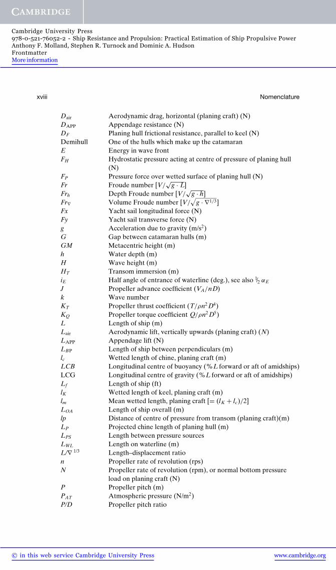
Nomenclature
A Wetted surface area, thin ship theory (m2)A0 Propeller disc area [π D2/4]AD Propeller developed blade area ratio, or developed blade area
(m2)AE Propeller expanded blade area ratioAP Projected bottom planing area of planing hull (m2) or projected
area of propeller blade (m2)AT Transverse frontal area of hull and superstructure above
water (m2)AX Midship section area (m2)b Breadth of catamaran demihull (m), or mean chine beam of
planing craft (m)B Breadth of monohull or overall breadth of catamaran (m)Bpa Mean breadth over chines [= AP/LP] (m)Bpx Maximum breadth over chines (m)BWL Breadth on waterline (m)c Section chord (m)CA Model-ship correlation allowance coefficientCB Block coefficientCDair Coefficient of air resistance [Rair/1/2ρa ATV2]Cf Local coefficient of frictional resistanceCF Coefficient of frictional resistance [RF/1/2ρW SV2]CL Lift coefficientCM Midship coefficient [AX/(B × T)]CP Prismatic coefficient [∇/(L× AX)] or pressure coefficientCR Coefficient of residuary resistance [RR/1/2ρSV2]CS Wetted surface coefficient [S/
√∇ · L]CT Coefficient of total resistance [RT/1/2ρSV2]CV Coefficient of viscous resistance [RV/1/2ρSV2]CW Coefficient of wave resistance [RW/1/2ρSV2]CWP Coefficient of wave pattern resistance [RWP/1/2ρSV2]D Propeller diameter (m)
xvii
www.cambridge.org© in this web service Cambridge University Press
Cambridge University Press978-0-521-76052-2 - Ship Resistance and Propulsion: Practical Estimation of Ship Propulsive PowerAnthony F. Molland, Stephen R. Turnock and Dominic A. HudsonFrontmatterMore information
xviii Nomenclature
Dair Aerodynamic drag, horizontal (planing craft) (N)DAPP Appendage resistance (N)DF Planing hull frictional resistance, parallel to keel (N)Demihull One of the hulls which make up the catamaranE Energy in wave frontFH Hydrostatic pressure acting at centre of pressure of planing hull
(N)FP Pressure force over wetted surface of planing hull (N)Fr Froude number [V/
√g · L]
Frh Depth Froude number [V/√
g · h]Fr∇ Volume Froude number [V/
√g · ∇1/3]
Fx Yacht sail longitudinal force (N)Fy Yacht sail transverse force (N)g Acceleration due to gravity (m/s2)G Gap between catamaran hulls (m)GM Metacentric height (m)h Water depth (m)H Wave height (m)HT Transom immersion (m)iE Half angle of entrance of waterline (deg.), see also 1/2 αE
J Propeller advance coefficient (VA/nD)k Wave numberKT Propeller thrust coefficient (T/ρn2 D4)KQ Propeller torque coefficient Q/ρn2 D5)L Length of ship (m)Lair Aerodynamic lift, vertically upwards (planing craft) (N)LAPP Appendage lift (N)LBP Length of ship between perpendiculars (m)lc Wetted length of chine, planing craft (m)LCB Longitudinal centre of buoyancy (%L forward or aft of amidships)LCG Longitudinal centre of gravity (%L forward or aft of amidships)Lf Length of ship (ft)lK Wetted length of keel, planing craft (m)lm Mean wetted length, planing craft [= (lK + lc)/2]LOA Length of ship overall (m)lp Distance of centre of pressure from transom (planing craft)(m)LP Projected chine length of planing hull (m)LPS Length between pressure sourcesLWL Length on waterline (m)L/∇ 1/3 Length–displacement ration Propeller rate of revolution (rps)N Propeller rate of revolution (rpm), or normal bottom pressure
load on planing craft (N)P Propeller pitch (m)PAT Atmospheric pressure (N/m2)P/D Propeller pitch ratio
www.cambridge.org© in this web service Cambridge University Press
Cambridge University Press978-0-521-76052-2 - Ship Resistance and Propulsion: Practical Estimation of Ship Propulsive PowerAnthony F. Molland, Stephen R. Turnock and Dominic A. HudsonFrontmatterMore information
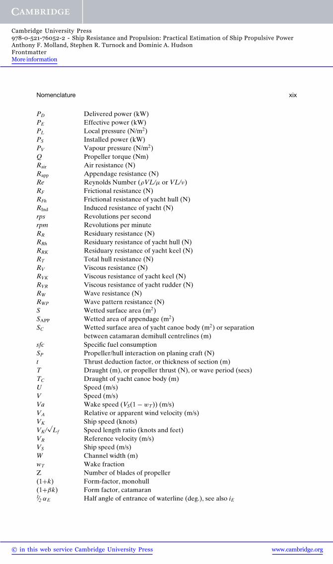
Nomenclature xix
PD Delivered power (kW)PE Effective power (kW)PL Local pressure (N/m2)PS Installed power (kW)PV Vapour pressure (N/m2)Q Propeller torque (Nm)Rair Air resistance (N)Rapp Appendage resistance (N)Re Reynolds Number (ρVL/μ or VL/ν)RF Frictional resistance (N)RFh Frictional resistance of yacht hull (N)RInd Induced resistance of yacht (N)rps Revolutions per secondrpm Revolutions per minuteRR Residuary resistance (N)RRh Residuary resistance of yacht hull (N)RRK Residuary resistance of yacht keel (N)RT Total hull resistance (N)RV Viscous resistance (N)RVK Viscous resistance of yacht keel (N)RVR Viscous resistance of yacht rudder (N)RW Wave resistance (N)RWP Wave pattern resistance (N)S Wetted surface area (m2)SAPP Wetted area of appendage (m2)SC Wetted surface area of yacht canoe body (m2) or separation
between catamaran demihull centrelines (m)sfc Specific fuel consumptionSP Propeller/hull interaction on planing craft (N)t Thrust deduction factor, or thickness of section (m)T Draught (m), or propeller thrust (N), or wave period (secs)TC Draught of yacht canoe body (m)U Speed (m/s)V Speed (m/s)Va Wake speed (VS(1 − wT)) (m/s)VA Relative or apparent wind velocity (m/s)VK Ship speed (knots)VK/
√Lf Speed length ratio (knots and feet)
VR Reference velocity (m/s)VS Ship speed (m/s)W Channel width (m)wT Wake fractionZ Number of blades of propeller(1+k) Form-factor, monohull(1+βk) Form factor, catamaran1/2 αE Half angle of entrance of waterline (deg.), see also iE
www.cambridge.org© in this web service Cambridge University Press
Cambridge University Press978-0-521-76052-2 - Ship Resistance and Propulsion: Practical Estimation of Ship Propulsive PowerAnthony F. Molland, Stephen R. Turnock and Dominic A. HudsonFrontmatterMore information
xx Nomenclature
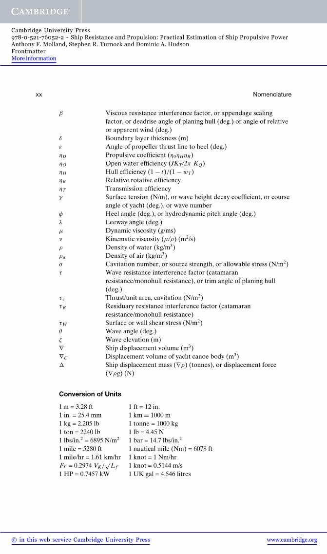
β Viscous resistance interference factor, or appendage scalingfactor, or deadrise angle of planing hull (deg.) or angle of relativeor apparent wind (deg.)
δ Boundary layer thickness (m)ε Angle of propeller thrust line to heel (deg.)ηD Propulsive coefficient (η0ηHηR)ηO Open water efficiency (JKT/2π KQ)ηH Hull efficiency (1 − t)/(1 − wT)ηR Relative rotative efficiencyηT Transmission efficiencyγ Surface tension (N/m), or wave height decay coefficient, or course
angle of yacht (deg.), or wave numberφ Heel angle (deg.), or hydrodynamic pitch angle (deg.)λ Leeway angle (deg.)μ Dynamic viscosity (g/ms)ν Kinematic viscosity (μ/ρ) (m2/s)ρ Density of water (kg/m3)ρa Density of air (kg/m3)σ Cavitation number, or source strength, or allowable stress (N/m2)τ Wave resistance interference factor (catamaran
resistance/monohull resistance), or trim angle of planing hull(deg.)
τ c Thrust/unit area, cavitation (N/m2)τR Residuary resistance interference factor (catamaran
resistance/monohull resistance)τW Surface or wall shear stress (N/m2)θ Wave angle (deg.)ζ Wave elevation (m)∇ Ship displacement volume (m3)∇C Displacement volume of yacht canoe body (m3)� Ship displacement mass (∇ρ) (tonnes), or displacement force
(∇ρg) (N)
Conversion of Units
1 m = 3.28 ft 1 ft = 12 in.1 in. = 25.4 mm 1 km = 1000 m1 kg = 2.205 lb 1 tonne = 1000 kg1 ton = 2240 lb 1 lb = 4.45 N1 lbs/in.2 = 6895 N/m2 1 bar = 14.7 lbs/in.2
1 mile = 5280 ft 1 nautical mile (Nm) = 6078 ft1 mile/hr = 1.61 km/hr 1 knot = 1 Nm/hrFr = 0.2974 VK/
√Lf 1 knot = 0.5144 m/s
1 HP = 0.7457 kW 1 UK gal = 4.546 litres

www.cambridge.org© in this web service Cambridge University Press
Cambridge University Press978-0-521-76052-2 - Ship Resistance and Propulsion: Practical Estimation of Ship Propulsive PowerAnthony F. Molland, Stephen R. Turnock and Dominic A. HudsonFrontmatterMore information
Abbreviations
ABS American Bureau of ShippingAEW Admiralty Experiment Works (UK)AFS Antifouling systems on shipsAHR Average hull roughnessAP After perpendicularARC Aeronautical Research Council (UK)ATTC American Towing Tank ConferenceBDC Bottom dead centreBEM Boundary element methodBEMT Blade element-momentum theoryBMEP Brake mean effective pressureBMT British Maritime TechnologyBN Beaufort NumberBSRA British Ship Research AssociationBTTP British Towing Tank PanelCAD Computer-aided designCCD Charge-coupled deviceCFD Computational fluid dynamicsCG Centre of gravityCLR Centre of lateral resistanceCODAG Combined diesel and gasCP Controllable pitch (propeller)CSR Continuous service ratingDES Detached eddy simulationDNS Direct numerical simulationDNV Det Norske VeritasDSYHS Delft systematic yacht hull seriesDTMB David Taylor Model BasinEFD Experimental fluid dynamicsFEA Finite element analysisFP Forward perpendicular, or fixed pitch (propeller)FRP Fibre-reinforced plasticFV Finite volume
xxi

www.cambridge.org© in this web service Cambridge University Press
Cambridge University Press978-0-521-76052-2 - Ship Resistance and Propulsion: Practical Estimation of Ship Propulsive PowerAnthony F. Molland, Stephen R. Turnock and Dominic A. HudsonFrontmatterMore information
xxii Abbreviations
GL Germanischer LloydGPS Global Positioning SystemHP HorsepowerHSVA Hamburg Ship Model BasinIESS Institute of Engineers and Shipbuilders in ScotlandIMarE Institute of Marine Engineers (became IMarEST from 2001)IMarEST Institute of Marine Engineering, Science and TechnologyIMechE Institution of Mechanical EngineersIMO International Maritime OrganisationINSEAN Instituto di Architectura Navale (Rome)ISO International Standards OrganisationITTC International Towing Tank ConferenceJASNAOE Japan Society of Naval Architects and Ocean EngineersLCG Longitudinal centre of gravityLDA Laser Doppler anemometryLDV Laser Doppler velocimetryLE Leading edge of foil or finLES Large eddy simulationLR Lloyd’s Register of ShippingMAA Mean apparent amplitudeMARIN Maritime Research Institute of the Netherlands (formerly NSMB)MCR Maximum continuous ratingMEMS Microelectromechanical systemsNACA National Advisory Council for Aeronautics (USA)NECIES North East Coast Institution of Engineers and ShipbuildersNPL National Physical Laboratory (UK)NSMB The Netherlands Ship Model Basin (later to become MARIN)NTUA National Technical University of AthensORC Offshore Racing CongressP PortPIV Particle image velocimetryQPC Quasi propulsive coefficientRANS Reynolds Averaged Navier–StokesRB Round back (section)RINA Royal Institution of Naval ArchitectsROF Rise of floorrpm Revolutions per minuterps Revolutions per secondS StarboardSAC Sectional area curveSCF Ship correlation factorSG Specific gravitySNAJ Society of Naval Architects of Japan (later to become JASNAOE)SNAK Society of Naval Architects of KoreaSNAME Society of Naval Architects and Marine Engineers (USA)SP Self-propulsionSSPA Statens Skeppsprovingansalt, Gotaborg, Sweden

www.cambridge.org© in this web service Cambridge University Press
Cambridge University Press978-0-521-76052-2 - Ship Resistance and Propulsion: Practical Estimation of Ship Propulsive PowerAnthony F. Molland, Stephen R. Turnock and Dominic A. HudsonFrontmatterMore information
Abbreviations xxiii
STG Schiffbautechnische Gesellschaft, HamburgTBT TributyltinTDC Top dead centreTDW Tons deadweightTE Trailing edge of foil or finTEU Twenty foot equivalent unit [container]UTS Ultimate tensile stressVCB Vertical centre of buoyancyVLCC Very large crude carrierVPP Velocity prediction programVWS Versuchsanstalt fur Wasserbau und Schiffbau Berlin (Berlin
Model Basin)WUMTIA Wolfson Unit for Marine Technology and Industrial
Aerodynamics, University of Southampton
www.cambridge.org© in this web service Cambridge University Press
Cambridge University Press978-0-521-76052-2 - Ship Resistance and Propulsion: Practical Estimation of Ship Propulsive PowerAnthony F. Molland, Stephen R. Turnock and Dominic A. HudsonFrontmatterMore information
Figure Acknowledgements
The authors acknowledge with thanks the assistance given by the following com-panies and publishers in permitting the reproduction of illustrations and tables fromtheir publications:
Figures 8.5, 10.7, 10.9, 10.10, 10.12, 12.24, 14.17, 14.18, 14.19, 14.20, 14.21, 14.22,14.23, 14.24, 14.30, 15.4, 15.14, 15.15, 15.17, 16.1, 16.2 and Tables A3.13,A3.14, A3.15, A4.3 reprinted courtesy of The Society of Naval Architects andMarine Engineers (SNAME), New York.
Figures 3.28, 3.29, 4.4, 4.5, 4.6, 7.6, 7.10, 7.16, 7.28, 8.4, 10.2, 10.3, 10.4, 10.5,10.13, 10.14, 10.20, 10.21, 12.26, 14.15, 16.7, 16.8, 16.9, 16.10, 16.15, 16.16,16.17, 16.19, 16.26 and Tables A3.1, A3.6, A3.24, A3.25, A3.26, A4.4, A4.5reprinted courtesy of The Royal Institution of Naval Architects (RINA),London.
Figures 10.11, 16.24 and Tables A3.2, A3.3, A3.4, A3.5, A3.12, A3.23, A4.1,A4.2, A4.6 reprinted courtesy of IOS Press BV, Amsterdam.
Figures 4.8, 8.3, 8.12, 8.13, 16.3, 16.4, 16.5, 16.6, 16.13 reprinted courtesy ofMARIN, Wageningen.
Figure 10.23 and Tables 10.13, 10.14, 10.15, 10.16, 10.17 reprinted courtesy ofThe HISWA Symposium Foundation, Amsterdam.
Figures A1.1, A1.7, A1.8 and Sections A1.1–A1.7 reprinted courtesy of ElsevierLtd., Oxford.
Figure 10.22 reprinted courtesy of The Japan Society of Naval Architects andOcean Engineers (JASNAOE), Tokyo (formerly The Society of Naval Archi-tects of Japan (SNAJ), Tokyo).
Figure 3.10 reprinted courtesy of WUMTIA, University of Southampton andDubois Naval Architects Ltd., Lymington.
Figure 7.3 reprinted courtesy of WUMTIA, University of Southampton.Figure 12.29 reprinted courtesy of The University of Newcastle upon Tyne.Figures 12.31, 13.9, 15.17 reprinted courtesy of The North East Coast Institution
of Engineers and Shipbuilders (NECIES), Newcastle upon Tyne.Table A3.7 reprinted courtesy of Ship Technology Research, Hamburg.Table A3.27 reprinted courtesy of STG, Hamburg.
xxv

www.cambridge.org© in this web service Cambridge University Press
Cambridge University Press978-0-521-76052-2 - Ship Resistance and Propulsion: Practical Estimation of Ship Propulsive PowerAnthony F. Molland, Stephen R. Turnock and Dominic A. HudsonFrontmatterMore information
xxvi Figure Acknowledgements
Figure 10.6 reprinted courtesy of BMT Group Ltd., Teddington.Figure 12.25 reprinted courtesy of The Institution of Mechanical Engineers
(IMechE), London.Figures 16.27, 16.28 and Tables 16.8, 16.9 reprinted courtesy of The Offshore
Racing Congress (ORC).