Shimmer Sensing LabVIEW Instrument Driver Library
157
Copyright © Shimmer Research 2013 Realtime Technologies Ltd LabVIEW Instrument Driver All rights reserved Rev 1.5a 1 ShimmerSensing LabVIEW Instrument Driver Library User Manual Revision 2.7a
Transcript of Shimmer Sensing LabVIEW Instrument Driver Library
Copyright © Shimmer Research 2013
Realtime Technologies Ltd LabVIEW Instrument Driver
All rights reserved Rev 1.5a
1
ShimmerSensing LabVIEW
Instrument Driver Library
User Manual
Revision 2.7a
Copyright © Shimmer 2017
Realtime Technologies Ltd ShimmerSensing LabVIEW Instrument Driver Library
All rights reserved Rev2.7a
1
Legal Notices and Disclaimer
Redistribution IS permitted provided that the following conditions are met: Redistributions must retain the copyright notice, and the following disclaimer. Redistributions in electronic form must reproduce the above copyright notice, this list of conditions and the following disclaimer in the documentation and/or other materials provided with the document. Neither the name of Shimmer Research, or Realtime Technologies Ltd. nor the names of its contributors may be used to endorse or promote products derived from this document without specific prior written permission.
THIS DOCUMENT IS PROVIDED BY THE COPYRIGHT HOLDERS AND CONTRIBUTORS "AS IS" AND ANY EXPRESS OR IMPLIED WARRANTIES, INCLUDING, BUT NOT LIMITED TO, THE IMPLIED WARRANTIES OF MERCHANTABILITY AND FITNESS FOR A PARTICULAR PURPOSE ARE DISCLAIMED. IN NO EVENT SHALL THE COPYRIGHT OWNER OR CONTRIBUTORS BE LIABLE FOR ANY DIRECT, INDIRECT, INCIDENTAL, SPECIAL, EXEMPLARY, OR CONSEQUENTIAL DAMAGES (INCLUDING, BUT NOT LIMITED TO, PROCUREMENT OF SUBSTITUTE GOODS OR SERVICES; LOSS OF USE, DATA, OR PROFITS; OR BUSINESS INTERRUPTION) HOWEVER CAUSED AND ON ANY THEORY OF LIABILITY, WHETHER IN CONTRACT, STRICT LIABILITY, OR TORT (INCLUDING NEGLIGENCE OR OTHERWISE) ARISING IN ANY WAY OUT OF THE USE OF THIS DOCUMENT, EVEN IF ADVISED OF THE POSSIBILITY OF SUCH DAMAGE.
Copyright © Shimmer 2017
Realtime Technologies Ltd ShimmerSensing LabVIEW Instrument Driver Library
All rights reserved Rev2.7a
2
Table of Contents
1. Introduction ......................................................................................................................... 3 1.1. Scope of this Document .......................................................................................................... 3
1.2. Important Note regarding Legacy Applications ...................................................................... 3
1.3. How to use this Document...................................................................................................... 4
2. Pre-Requisites ...................................................................................................................... 5
3. Installation ........................................................................................................................... 6
4. ShimmerSensing LabVIEW Instrument Driver Library ............................................................. 7 4.1. Exploring the Shimmer Instrument Driver Library .................................................................. 7
4.2. Example Application VIs ........................................................................................................ 11
4.3. Integrated VIs ........................................................................................................................ 48
4.4. Instrument Driver VIs ............................................................................................................ 61
4.5. PPGtoHeartRateConverter Class ......................................................................................... 140
4.6. ECGtoHeartRateConverter Class ......................................................................................... 144
4.7. Synchronisation Class .......................................................................................................... 149
5. Support ............................................................................................................................ 151
Appendix I – Alignment Matrix, Sensitivity Matrix and Offset Vector ......................................... 152 Alignment Matrix ............................................................................................................................ 152
Sensitivity Matrix ............................................................................................................................ 153
Offset Vector ................................................................................................................................... 153
Appendix II – Streaming from more than 7 Shimmers via Bluetooth on a Single Computer ......... 154
References ............................................................................................................................... 155
Copyright © Shimmer 2017
Realtime Technologies Ltd ShimmerSensing LabVIEW Instrument Driver Library
All rights reserved Rev2.7a
3
1. Introduction
The ShimmerSensing LabVIEW Instrument Driver Library is a library of LabVIEW VIs designed to assist
users of the Shimmer3, and of legacy hardware (Shimmer2 and Shimmer2r), in the development of
Shimmer based applications in LabVIEW. The ShimmerSensing LabVIEW Instrument Driver Library is
not intended to be the answer to all host side application requirements, but instead provides a set of
building blocks for developers.
The library offers a number of different low level Instrument Driver VIs for different Shimmer
operations such as configuring, triggering and reading data. The library also includes a set of fully
Integrated Shimmer VIs which are essentially higher level VIs integrating all of the functionality of
the lower level Instrument Driver VIs. In addition the library includes a number of Example
Application VIs to assist with Shimmer LabVIEW application development. The Example Application
VIs may be used in their own right or may be modified by the LabVIEW developer to form the basis
for additional applications.
The Instrument Drivers VIs were developed based on the core principals of LabVIEW instrument
driver development. Although their design does not yet adhere precisely to the principals outlined in
the National Instruments Instrument Driver Guidelines, an effort has been made to do so and it is
planned to bring the library directly in line with these principles in the future.
1.1. Scope of this Document
National Instruments provides extensive online and offline documentation for all core LabVIEW
components. This documentation limits itself to explaining the Shimmer based functionality which
has been developed through the integration of different LabVIEW components. Whilst an effort has
been made to provide as much information as is required, the user may need to develop some
further understanding through reading of LabVIEW help files and studying the VI block diagrams
which include text comments where appropriate.
1.2. Important Note regarding Legacy Applications
The ShimmerSensing LabVIEW Instrument Driver Library v2.0 (and later) constitutes a significant
rework of the instrument driver. It is important to note that full backwards compatibility with
previous versions of the instrument driver has not been maintained. The reason for this is that the
feature set of the Shimmer3 has vastly outgrown the previously existing instrument driver
infrastructure and unlocking the new capability was becoming a very cumbersome and error prone
process.
Although full backwards compatibility has not been maintained, a VI has been included which
provides an interface between the legacy version of the integrated Shimmer VI and the new
integrated VI. At the very least, this legacy interface should be used to upgrade all applications that
were built using v1.x of the Shimmer LabVIEW Instrument Driver Library. See the
ShimmerLegacyInterface.vi section of this document for more information about the
ShimmerLegacyInterface VI.
Copyright © Shimmer 2017
Realtime Technologies Ltd ShimmerSensing LabVIEW Instrument Driver Library
All rights reserved Rev2.7a
4
The main changes in the infrastructure are highlighted in the ShimmerLegacyInterface.vi section of
this document. To differentiate between the legacy Shimmer LabVIEW Instrument Driver Library,
which was referred to as the "Shimmer Library", the ShimmerSensing LabVIEW Instrument Driver
Library v2.0 and later will be referred to as the "ShimmerSensing Library".
1.3. How to use this Document
The main body of this document is Section 4 ShimmerSensing LabVIEW Instrument Driver Library,
which is divided into four sub-sections:
1. Exploring the Shimmer Instrument Driver Library
2. Example Application VIs
3. Integrated VIs
4. Instrument Driver VIs
It may not be necessary for a user to familiarize themselves with all four sub-sections. The sub-
sections which a user should read will depend on the needs of the user. The table below
provides a guide as to which sub-section should be studied depending on the user's needs.
User Needs Required Reading Sub-Section Name
User wants to acquire sensor data from up
to four Shimmers and store it to file.
Exploring the Shimmer Instrument Driver
Library
Example Application VIs
User wants to develop a better
understanding of how the Example
Application VIs work.
User wants to develop their own Shimmer
LabVIEW Applications
Exploring the Shimmer Instrument Driver
Library
Integrated VIs
Example Application VIs
User wants to develop a deeper
understanding of how the Integrated VIs
work
User wants to develop their own Integrated
VI.
User wants to implement some
functionality which is best achieved using
VIs at a lower level to the Integrated VIs
Exploring the Shimmer Instrument Driver
Library
Integrated VIs
Instrument Driver VIs
Copyright © Shimmer 2017
Realtime Technologies Ltd ShimmerSensing LabVIEW Instrument Driver Library
All rights reserved Rev2.7a
5
2. Pre-Requisites
In order to use the ShimmerSensing LabVIEW Instrument Driver Library you will need the following:
1. National Instruments LabVIEW Version 10.0 or later installed on your PC.
Please note that the Instrument Driver was developed in LabVIEW version 13.0.
2. National Instruments VISA installed as part of you LabVIEW installation. You can download
the latest version of VISA by clicking the Downloads link at http://www.ni.com/visa/.
3. The appropriate ShimmerSensing LabVIEW X.X Instrument Driver Library RevX.X package.
Note: There are different versions of the library package available for download depending
on which version of LabVIEW the user is using. The user should make sure that they have
downloaded the correct version.
The naming convention of the download packages (ShimmerSensing LabVIEW X.X
Instrument Driver Library RevX.X ) is as follows
Shimmer indicates that the library is for use with the Shimmer2 and Shimmer2r.
LabVIEW X.X indicates that the library is for use with the LabVIEW version X.X.
RevX.X indicates the revision number of the library.
A link to the library package download is available from
www.shimmersensing.com/download and includes the following:
a. ShimmerSensing LabVIEW Instrument Driver Library project, library and source files
b. ShimmerSensing LabVIEW Library User Manual.pdf.
c. Shimmer Readme.html
Download the library package, extract the files and follow the installation instructions
outlined in the Installation section below.
4. A Shimmer 3 device programmed with LogAndStream firmware or a Shimmer2/Shimmer2r
device programmed with the latest version of BtStream.
NOTE: All Shimmers are shipped pre-programmed with the LogAndStream firmware. If for
some reason you need to reprogram your Shimmer you can do so with Consensys software
in the section ‘Manage Devices’.
5. The Shimmer needs to be paired with the PC (over Bluetooth).
Copyright © Shimmer 2017
Realtime Technologies Ltd ShimmerSensing LabVIEW Instrument Driver Library
All rights reserved Rev2.7a
6
3. Installation
1. Included in the ShimmerSensing LabVIEW Instrument Driver Library package is a folder called
ShimmerSensing which contains the ShimmerSensing LabVIEW Instrument Driver Library project,
library and source files.
Copy the ShimmerSensing folder to the LabVIEW instrument drivers library directory
<LabVIEW>\instr.lib\ on your PC.
For example in MS Windows a typical path for the instrument drivers library directory may be:
C:\Program Files\National Instruments\LabVIEW 2010\instr.lib\
In MAC OS X a typical path for the instrument drivers library directory may be:
/Applications/National Instruments/LabVIEW 2010/instr.lib/
Note: If LabVIEW is already running you will need to restart LabVIEW for the installation to take
effect.
2. Install the appropriate firmware image onto your Shimmer device using Consensys software.
For Shimmer3, LogAndStream v0.7.0 (or later) is recommended.
For Shimmer2 or Shimmer2r, BtStream v1.2.0 (or later) is recommended.
Earlier versions of the Shimmer are not supported.
Copyright © Shimmer 2017
Realtime Technologies Ltd ShimmerSensing LabVIEW Instrument Driver Library
All rights reserved Rev2.7a
7
4. ShimmerSensing LabVIEW Instrument Driver Library
4.1. Exploring the Shimmer Instrument Driver Library
Upon successful installation of the ShimmerSensing LabVIEW Instrument Driver Library (referred to
as the ShimmerSensing Library for the remainder of the document) the user should now have the full
suite of Shimmer VIs available for use.
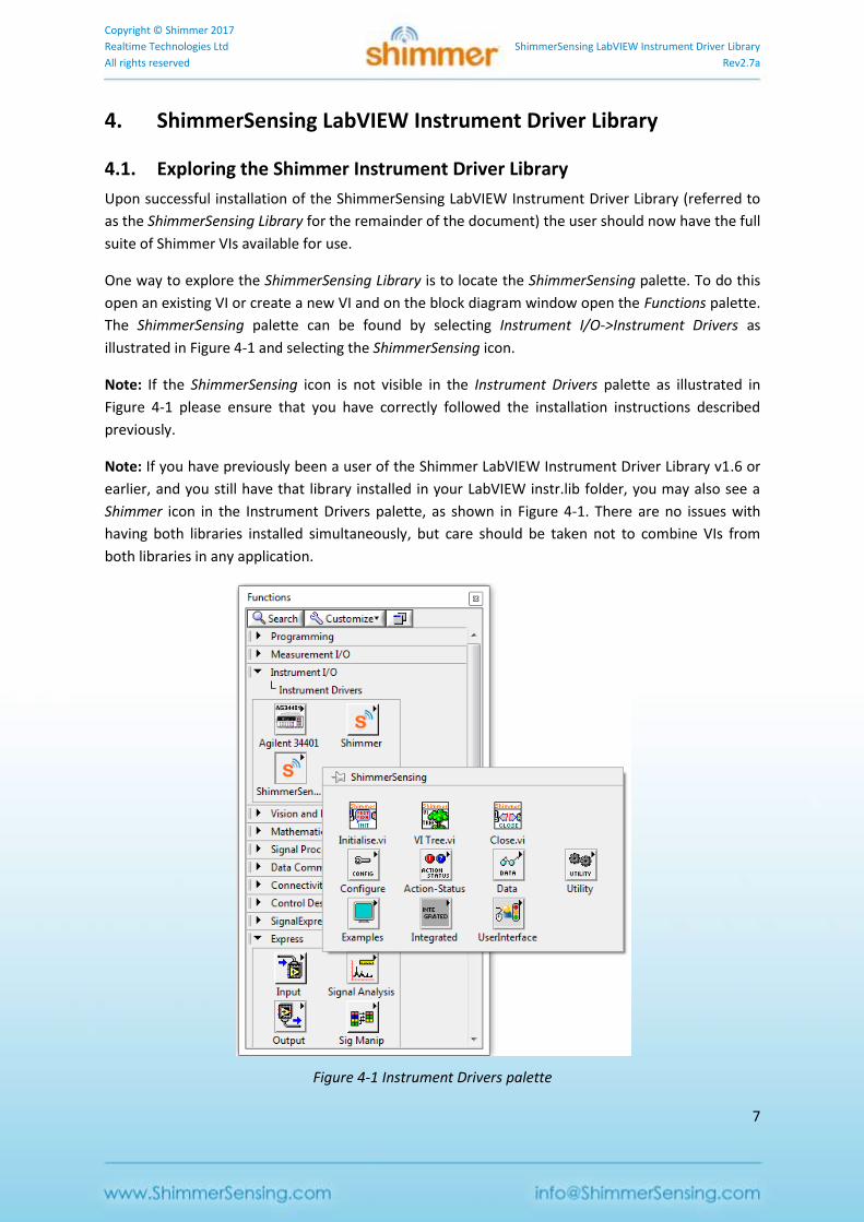
One way to explore the ShimmerSensing Library is to locate the ShimmerSensing palette. To do this
open an existing VI or create a new VI and on the block diagram window open the Functions palette.
The ShimmerSensing palette can be found by selecting Instrument I/O->Instrument Drivers as
illustrated in Figure 4-1 and selecting the ShimmerSensing icon.
Note: If the ShimmerSensing icon is not visible in the Instrument Drivers palette as illustrated in
Figure 4-1 please ensure that you have correctly followed the installation instructions described
previously.
Note: If you have previously been a user of the Shimmer LabVIEW Instrument Driver Library v1.6 or
earlier, and you still have that library installed in your LabVIEW instr.lib folder, you may also see a
Shimmer icon in the Instrument Drivers palette, as shown in Figure 4-1. There are no issues with
having both libraries installed simultaneously, but care should be taken not to combine VIs from
both libraries in any application.
Figure 4-1 Instrument Drivers palette
Copyright © Shimmer 2017
Realtime Technologies Ltd ShimmerSensing LabVIEW Instrument Driver Library
All rights reserved Rev2.7a
8
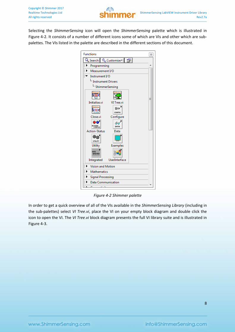
Selecting the ShimmerSensing icon will open the ShimmerSensing palette which is illustrated in
Figure 4-2. It consists of a number of different icons some of which are VIs and other which are sub-
palettes. The VIs listed in the palette are described in the different sections of this document.
Figure 4-2 Shimmer palette
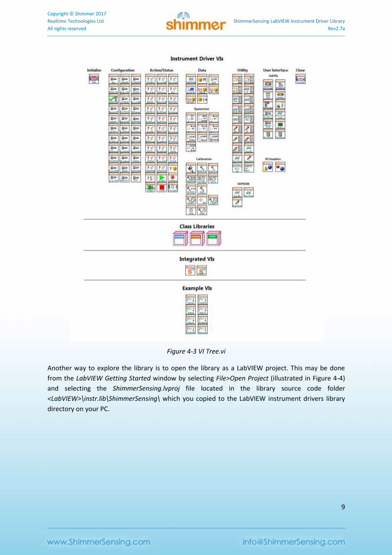
In order to get a quick overview of all of the VIs available in the ShimmerSensing Library (including in
the sub-palettes) select VI Tree.vi, place the VI on your empty block diagram and double click the
icon to open the VI. The VI Tree.vi block diagram presents the full VI library suite and is illustrated in
Figure 4-3.
Copyright © Shimmer 2017
Realtime Technologies Ltd ShimmerSensing LabVIEW Instrument Driver Library
All rights reserved Rev2.7a
9
Figure 4-3 VI Tree.vi
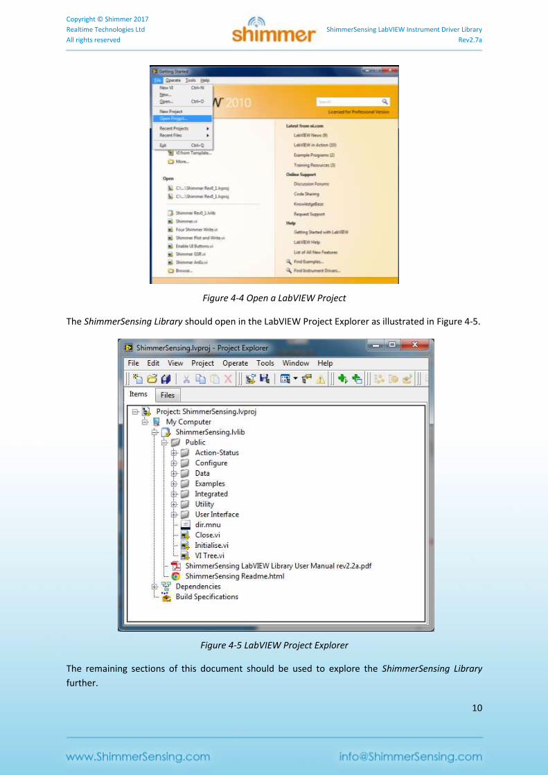
Another way to explore the library is to open the library as a LabVIEW project. This may be done
from the LabVIEW Getting Started window by selecting File>Open Project (illustrated in Figure 4-4)
and selecting the ShimmerSensing.lvproj file located in the library source code folder
<LabVIEW>\instr.lib\ShimmerSensing\ which you copied to the LabVIEW instrument drivers library
directory on your PC.
Copyright © Shimmer 2017
Realtime Technologies Ltd ShimmerSensing LabVIEW Instrument Driver Library
All rights reserved Rev2.7a
10
Figure 4-4 Open a LabVIEW Project
The ShimmerSensing Library should open in the LabVIEW Project Explorer as illustrated in Figure 4-5.
Figure 4-5 LabVIEW Project Explorer
The remaining sections of this document should be used to explore the ShimmerSensing Library
further.

Copyright © Shimmer 2017
Realtime Technologies Ltd ShimmerSensing LabVIEW Instrument Driver Library
All rights reserved Rev2.7a
11
4.2. Example Application VIs
The Example Application VIs outlined in this section can be used as standalone applications or as the
basis for more advanced LabVIEW applications. Only the front panel operation of the VIs is explained
in this section. The examples contain a number of Sub VIs which are not explained in the document.
Should the user wish to develop an understanding for the VI block diagrams and use the examples to
assist them in the development of Shimmer LabVIEW applications they should consider the
following.
The examples were designed to be used as part of an incremental learning process in conjunction
with this user manual. The different steps in the learning process are outlined below:
1. Develop a basic understanding of the Shimmer.vi by reading the Integrated VIs section of
this document.
2. Develop an understanding of basic Shimmer control in LabVIEW by studying the block
diagram of the Shimmer Basic Control.vi and operating the VI from its front panel.
3. Develop an understanding of Shimmer configuration in LabVIEW by studying the block
diagram of the Shimmer Control and Configure.vi and operating the VI from its front panel.
4. Develop an understanding of Shimmer data acquisition in LabVIEW by studying the block
diagram of the Shimmer Control and Configure.vi and operating the VI from its front panel.
5. Develop an understanding of LabVIEW based data acquisition from multiple Shimmers and
the use of different Integrated VIs by studying the block diagram of the Multi Shimmer
Template.vi / Multi Shimmer Sync Template.vi and operating the VI from its front panel.
Shimmer Basic Control.vi
The Shimmer Basic Control.vi is a VI which demonstrates basic usage of the Shimmer.vi. The
functionality it provides allows for basic control of the Shimmer such as connecting to the Shimmer
and streaming data from the Shimmer.
Starting Shimmer Basic Control.vi
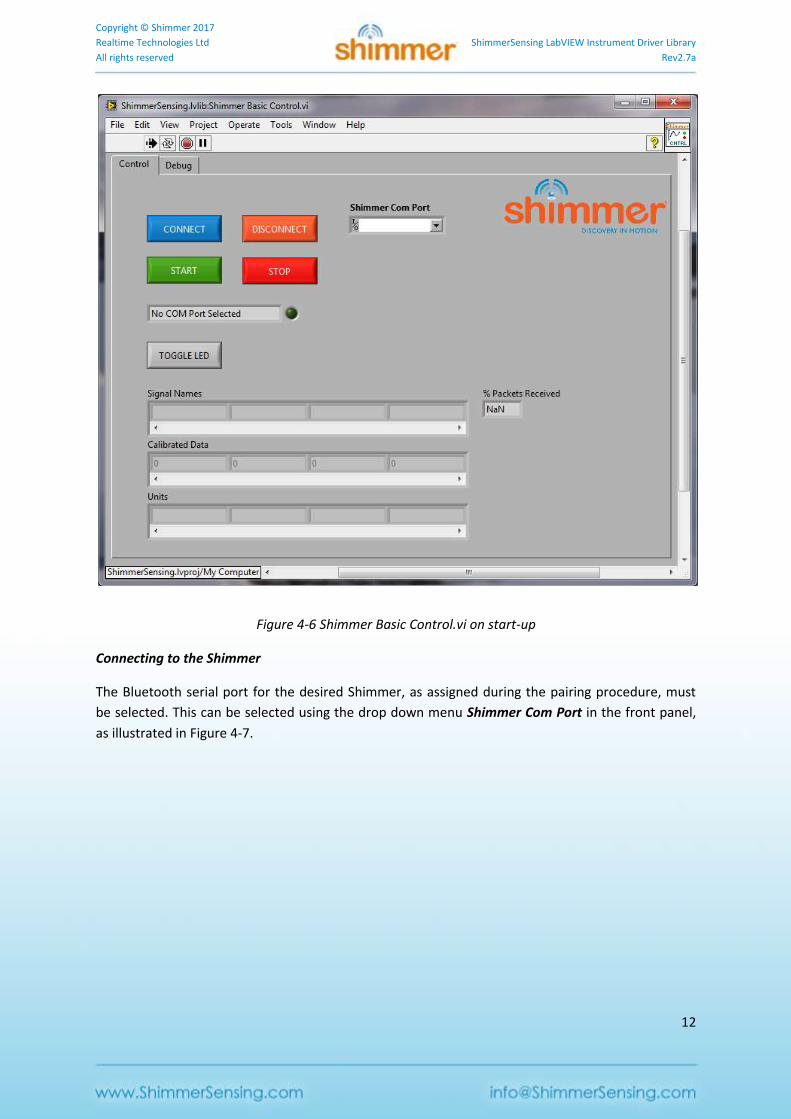
The Shimmer Basic Control.vi is located in the Examples folder of the ShimmerSensing Library. Open
the Shimmer Basic Control.vi front panel and run the VI. All controls for the VI are located on the
Control tab which is the front tab on the UI. The status display on the UI indicates the current status
of the Shimmer which on start up is No COM Port Selected as illustrated in Figure 4-6.
Copyright © Shimmer 2017
Realtime Technologies Ltd ShimmerSensing LabVIEW Instrument Driver Library
All rights reserved Rev2.7a
12
Figure 4-6 Shimmer Basic Control.vi on start-up
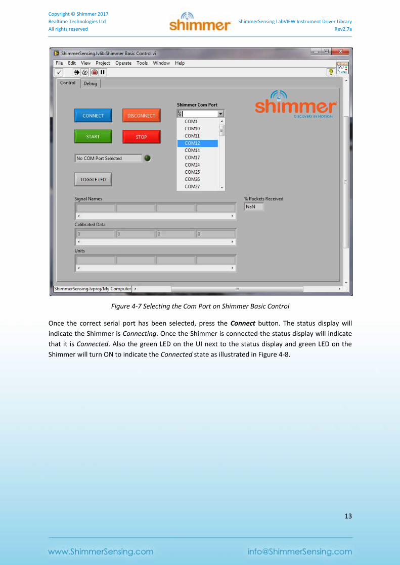
Connecting to the Shimmer
The Bluetooth serial port for the desired Shimmer, as assigned during the pairing procedure, must
be selected. This can be selected using the drop down menu Shimmer Com Port in the front panel,
as illustrated in Figure 4-7.
Copyright © Shimmer 2017
Realtime Technologies Ltd ShimmerSensing LabVIEW Instrument Driver Library
All rights reserved Rev2.7a
13
Figure 4-7 Selecting the Com Port on Shimmer Basic Control
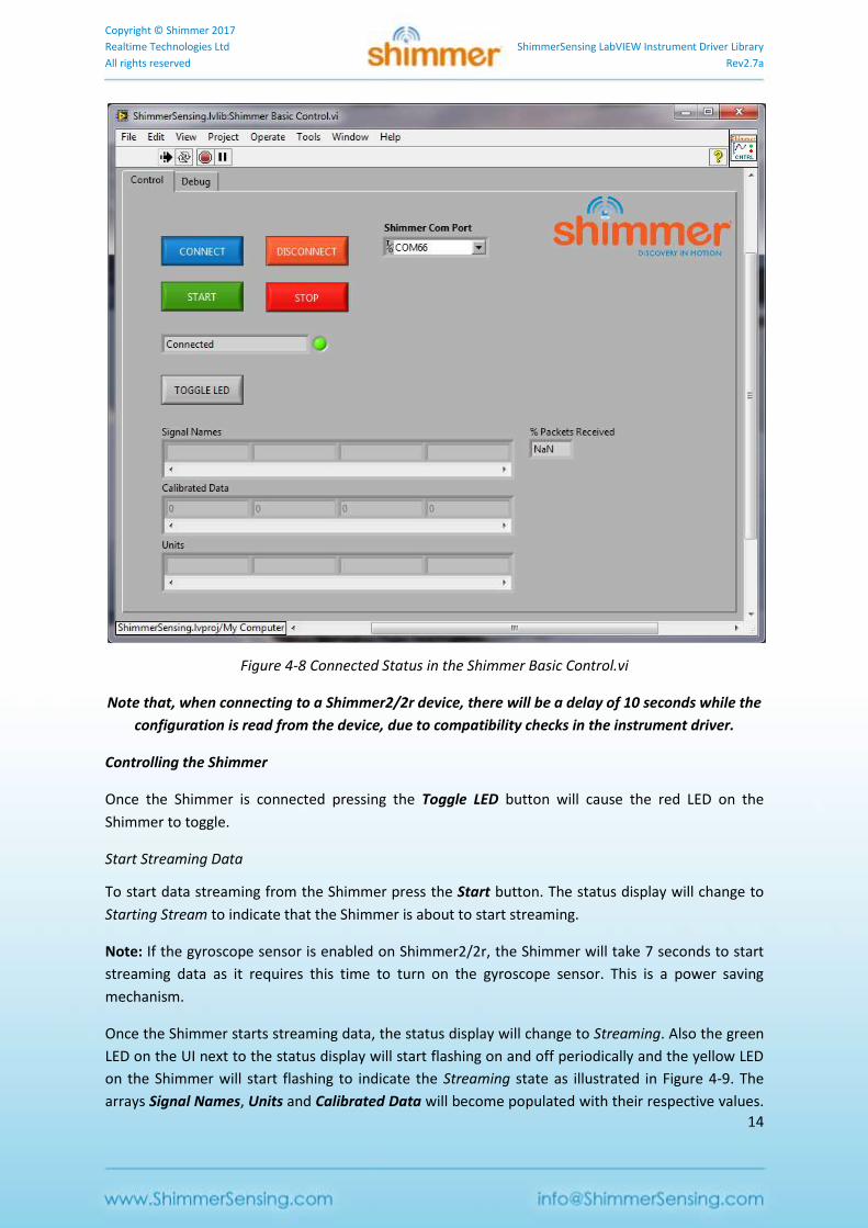
Once the correct serial port has been selected, press the Connect button. The status display will
indicate the Shimmer is Connecting. Once the Shimmer is connected the status display will indicate
that it is Connected. Also the green LED on the UI next to the status display and green LED on the
Shimmer will turn ON to indicate the Connected state as illustrated in Figure 4-8.
Copyright © Shimmer 2017
Realtime Technologies Ltd ShimmerSensing LabVIEW Instrument Driver Library
All rights reserved Rev2.7a
14
Figure 4-8 Connected Status in the Shimmer Basic Control.vi
Note that, when connecting to a Shimmer2/2r device, there will be a delay of 10 seconds while the
configuration is read from the device, due to compatibility checks in the instrument driver.
Controlling the Shimmer
Once the Shimmer is connected pressing the Toggle LED button will cause the red LED on the
Shimmer to toggle.
Start Streaming Data
To start data streaming from the Shimmer press the Start button. The status display will change to
Starting Stream to indicate that the Shimmer is about to start streaming.
Note: If the gyroscope sensor is enabled on Shimmer2/2r, the Shimmer will take 7 seconds to start
streaming data as it requires this time to turn on the gyroscope sensor. This is a power saving
mechanism.
Once the Shimmer starts streaming data, the status display will change to Streaming. Also the green
LED on the UI next to the status display will start flashing on and off periodically and the yellow LED
on the Shimmer will start flashing to indicate the Streaming state as illustrated in Figure 4-9. The
arrays Signal Names, Units and Calibrated Data will become populated with their respective values.
Copyright © Shimmer 2017
Realtime Technologies Ltd ShimmerSensing LabVIEW Instrument Driver Library
All rights reserved Rev2.7a
15
If there are more than four data signals available for viewing the horizontal scrollbar can be used to
view the additional elements of the arrays. Which data signals are available for viewing is dependent
on the configuration of the Shimmer which is not covered in the Shimmer Basic Control.vi example.
An asterisk after the Units indicates that default offset and sensitivity values from the sensor data
sheet have been used to calibrate the sensor data (e.g. mVolts*).
To improve the accuracy of your data when using the inertial sensors (accelerometer, gyroscope or
magnetometer), it is recommended that you use the standalone Shimmer 9DoF Calibration
Application which is available for download from the Shimmer website. The application supports the
calibration of the inertial sensors and the storage of the calibration parameters on the Shimmer.
When calibration parameters have been stored on the Shimmer, the Example Applications and any
data-handling VIs included in the ShimmerSensing Library will use the stored calibration parameters
instead of default calibration parameters.
Also, for the accelerometer, the Units may be followed by double asterisks (e.g. m/s2**). This
indicates that the calibration parameters which have been stored on the Shimmer are not valid
parameters for the current Accelerometer Range setting. This can be rectified by configuring the
Accelerometer Range to the setting that it was in when it was calibrated or by recalibrating the
Shimmer (using the Shimmer 9DoF Calibration Application) with the device configured to the desired
Accelerometer Range.
The indicator % Packets Received indicates the percentage of data packets transmitted by the
Shimmer which have been successfully received and processed by the Shimmer.vi.
Copyright © Shimmer 2017
Realtime Technologies Ltd ShimmerSensing LabVIEW Instrument Driver Library
All rights reserved Rev2.7a
16
Figure 4-9 Streaming Data in the Shimmer Basic Control.vi
Stop Streaming Data
To stop data streaming from the Shimmer press the Stop button. The status display will change to
Stopping Stream to indicate that the Shimmer is about to stop streaming. Once the Shimmer stops
streaming data the status display will return to Connected. Also the yellow LED on the UI next to the
status display will turn OFF and the yellow LED on the Shimmer will turn off. The green LEDs on the
UI and the Shimmer will remain ON and the UI should return to the condition illustrated in Figure
4-8.
Disconnecting from the Shimmer
To disconnect from the Shimmer press the Disconnect button. The Shimmer should return to its
original Disconnected state.
Shimmer Control and Configure.vi
Copyright © Shimmer 2017
Realtime Technologies Ltd ShimmerSensing LabVIEW Instrument Driver Library
All rights reserved Rev2.7a
17
Prior to reading this section the reader should have covered the section describing the Shimmer
Basic Control.vi. The Shimmer Control and Configure.vi is a VI which, along with providing control of
the Shimmer, allows the user to configure the shimmer settings.
Starting Shimmer Control and Configure.vi
The Shimmer Control and Configure.vi is located in the Examples folder of the ShimmerSensing
Library. Open the Shimmer Control and Configure.vi front panel and run the VI.
The Shimmer Control and Configure.vi Front Panel is very similar to the Shimmer Basic Control.vi with the exceptions that it has an additional tab Configure (illustrated in Figure 4-10) and it uses additional functionality to enable and disable certain UI buttons depending on the current state of the Shimmer.
Figure 4-10 Shimmer Control and Configure.vi on start-up
The reason for disabling buttons is to restrict invalid UI events from being triggered when the
Shimmer is in certain states.
When the VI is run initially only the Connect button will be active (as in Figure 4-10) however upon a
successful connection with a Shimmer other buttons will become active.
The Start Log And Stream button will only become active if LogAndStream firmware is detected on
the connected Shimmer device.
Copyright © Shimmer 2017
Realtime Technologies Ltd ShimmerSensing LabVIEW Instrument Driver Library
All rights reserved Rev2.7a
18
The Shimmer Control and Configure.vi Front Panel also has a Low Battery Warning LED, which
indicates that the Shimmer's battery has dropped below a user-defined threshold. Enabling the
battery monitor and setting the threshold will be discussed below.
Note: Battery monitoring is not supported on Shimmer2; Shimmer2r or Shimmer3 is
required for this functionality.
Configuring the Shimmer
When the Shimmer is in a Connected state the buttons on the Configure tab (Figure 4-11) can be
used configure the Shimmer. The configuration buttons serve the dual purpose of indicating the
current settings on the Shimmer and allowing the user to modify the settings. In Figure 4-11, the
Accelerometer and Magnetometer are enabled on a Shimmer2r.
Figure 4-11 Configuring the Shimmer: Shimmer2/2r
Copyright © Shimmer 2017
Realtime Technologies Ltd ShimmerSensing LabVIEW Instrument Driver Library
All rights reserved Rev2.7a
19
The hardware version is displayed towards the right-hand side of the Configure tab in the HW
Version field, where a value of 1 denotes Shimmer2, 2 denotes Shimmer2r and 3 denotes Shimmer3.
Certain options are greyed out depending on the hardware version of the device that is connected.
Figure 4-12 shows how the Configure tab might look with a Shimmer3 connected.
The FW Version field indicates the firmware type and version that is running on the Shimmer.
Figure 4-12 Configuration options for Shimmer3
The green LEDs in the Enable/Disable Sensors panel are used to enable and disable sensors, whilst
the Enable/Disable Expansion Channels panel contains LEDs to enable and disable the internal and
external expansion channels. An appropriate expansion board must be attached to the Shimmer to
allow meaningful results to be returned; however, an expansion board can be attached without
enabling its sensor(s) (no data will be acquired from the relevant sensor(s) in this case).
With the exception of the magnetometer on the Shimmer2/2r, a sensor can be enabled without its
daughter board being attached; however, this results in redundant data being sampled and
transmitted by the Shimmer, thus inefficiencies and power wastage. Note that if the magnetometer
is enabled and streaming started without a 9DoF daughter board attached on a Shimmer2/2r device,
a reset will be needed to return to normal device behaviour.
Copyright © Shimmer 2017
Realtime Technologies Ltd ShimmerSensing LabVIEW Instrument Driver Library
All rights reserved Rev2.7a
20
Multiple sensors from different expansion boards (conflicting sensors) cannot be enabled at the
same time. If a conflicting sensor is enabled any other conflicting sensors will be automatically
disabled.
Certain sensor and expansion channel options are greyed out depending on the hardware version of
the device that is connected. Users should note that some of the controls that have been provided in
the example are placeholders, intended for future use, and are not currently enabled for any HW
version. Furthermore, only those sensor settings which are relevant for currently enabled sensors
are available for selection; for example, the Gyroscope Range is disabled and greyed out unless the
Gyroscope Sensor is enabled. For more details on the enabling/disabling of controls, see the Section
on Convert Sampling Rate to Hz.vi
Used as a SubVI to convert the firmware representation of sampling rate to a sampling rate
in Hz and a sampling period in s.
The input HW Version ensures compatibility with different hardware versions.
The input Sampling Rate (FW) should be an 8 bit hexadecimal value which defines the
sampling rate for all sensors on and attached to the Shimmer. Table 4-2 defines the range of
legitimate values and their corresponding sampling rate in the Shimmer.
The output Sampling Rate (Hz) is the sampling rate in Hz.
The output Sampling Period (s) is the sampling period in s.
User Interface VIs, later on in this document.
The Battery Monitor enable/disable button only has effect on the Shimmer2r and Shimmer3
devices. For the Shimmer3, there is a dedicated ADC channel for battery monitoring. For the
Shimmer2r, as explained in the Shimmer User Manual rev2Rx, the External Expansion ADC channels
can be multiplexed to measure the battery voltage either side of a SBR130S3 diode. This field
switches the Shimmer between sampling the External Expansion channels and the voltage channels.
To view/save the battery voltage data on Shimmer2/2r, the External Expansion channels, A0 and A7,
must be enabled in the Enable/Disable Sensors panel field. Turning on the Battery Monitor on a
Shimmer2/2r will automatically enable these External Expansion channels.
If the Battery Monitor is enabled, as described above, the Battery Voltage Threshold (mV) can be
set by the user to determine the voltage at which the low battery warning will be triggered. The
default value is 3400 mVolts. When the battery voltage reaches the threshold, the Low Battery
Warning LED on the Control tab will turn on and the yellow LED Shimmer will begin to flash to
indicate low battery.

Copyright © Shimmer 2017
Realtime Technologies Ltd ShimmerSensing LabVIEW Instrument Driver Library
All rights reserved Rev2.7a
21
The 5V Regulator enable/disable button sets the 5V regulator on the External Expansion1 board for
the Shimmer2/2r. This is not available on Shimmer3. The 5V regulator and the Strain Gauge share an
enable pin on the Shimmer2/2r. To prevent conflict, when the Strain Gauge is enabled, the 5V
Regulator button is greyed out on the UI and not configurable.
The Exp Power option enables or disables the 3V pin on the Shimmer3 internal expansion boards to
provide power to an external sensor. Please see the user manual for the relevant expansion board
for more details.
The Sensor Settings panel contains controls to configure the range and data rates of some of the
individual sensors. The Sampling Rate setting determines the sampling rate for all channels. The
Wide Range (WR) Accelerometer Range, Gyroscope Range, Magnetometer Range and GSR Range
parameters set the measurement range for the relevant sensors (where available) and they may be
modified by selecting the desired value from the drop down menu in the Sensor Settings panel. The
available range values will automatically be populated for the detected HW version.
If the Mag LP Mode option is enabled, the data rate of the magnetometer is set to a maximum of 10
Hz, regardless of the sampling rate setting, for lower power consumption (LP). If this setting is
disabled, then the data rate of the magnetometer is set to the match the sampling rate as closely as
possible, given the available options (0.5 Hz, 1.0 Hz, 2.0 Hz, 5.0 Hz, 10.0 Hz, 20.0 Hz, 50.0 Hz). Similar
options are available for the accelerometer and gyroscope on the Shimmer3 (WR Accel LP Mode and
Gyro LP Mode). The WR Accel HR Mode can be used to enable high resolution mode on the wide
range accelerometer on Shimmer3.
The Pressure Oversampling setting determines the resolution of the pressure sensor. Options are: 1
sample - ultra-low power, 2 samples - standard, 4 samples - high resolution, 8 samples - ultra-high
resolution.
The ExG Settings panel refers to controls that are specific to ECG or EMG and these controls will only
be enabled if ECG or EMG sensors are enabled.
The ExG Resolution setting determines whether ECG/EMG data will be sent in 16-bit or 24-bit
format. Users should note that 24-bit is the default format provided by the chips on the ExG
Expansion Board and, if 16-bit data is selected, the 7 least significant bits and the 1 most significant
bit of the ECG/EMG samples will be discarded by the firmware before transmitting the data over
Bluetooth. In the instrument driver, the calibration procedure handles the different data types.
The ExG Gain setting determines the software configurable gain of the ExG channels. The
recommended value for ECG or EMG data collection will be automatically chosen when the ECG or
EMG sensor, respectively, is enabled. Please refer to the Shimmer ExG User Guide for ECG or the
Shimmer ExG User Guide for EMG for more details.
The ExG Reference Electrode setting determines whether the reference voltage used in the ExG
amplifiers is a fixed reference voltage generated by the chip or taken from a feedback channel on
1 Formerly referred to as “AnEx”.
Copyright © Shimmer 2017
Realtime Technologies Ltd ShimmerSensing LabVIEW Instrument Driver Library
All rights reserved Rev2.7a
22
the body. Please refer to the Shimmer ECG User Guide or the Shimmer EMG User Guide for more
details.
The ExG Lead-Off settings are used to enable lead-off detection mode for the Shimmer3 and to
choose the parameters for lead-off detection, such as the current applied to the body and the
threshold levels.
The Respiration settings should only be used after a modification of the Shimmer3 ExG hardware;
please contact Shimmer if this functionality is required.
The Other Settings panel contains controls to configure options that are used by the Instrument
Driver only (i.e. these settings are not sent to the Shimmer device).
The 3D Orientation setting determines whether or not the orientation of the Shimmer in 3D space is
estimated by the instrument driver in real time. If this option is enabled, then the quaternion format
of the 3D orientation is estimated for each sample and output along with the calibrated sensor data.
The accelerometer, gyroscope and magnetometer are all automatically enabled if this option is
enabled, as the 3D orientation estimation relies on data from all of these sensors.
Enabling the Gyro In-Use Calibration option turns on a method that detects if the Shimmer is
motionless and updates the offset bias estimate for the gyroscope whenever it is motionless for 2
seconds. It is recommended to enable this option if 3D Orientation is enabled or if your application
relies heavily on very accurate gyroscope calibration. It should be noted that it is only the offset bias
and not the sensitivity that is continuously calibrated using this method.
For Shimmer3, there are two further options available: Reset Default Configuration and Reset
Default Calibration. These options are not available for Shimmer2/2r.
The Reset Default Configuration button will clear all user-selected configuration options and set the
default according to the following:
Enabled sensors: Low Noise Accel, Gyro, Mag, Battery.
Sampling rate: 51.2 Hz.
Wide Range Accel range: ±2g.
Wide Range Accel data rate: 100 Hz.
Mag range: ±1.3 Ga.
Mag data rate: 75 Hz.
Gyro range: ±500°/s.
Gyro data rate: 51.28 Hz.
Accel, Gyro and Mag LP Mode: OFF.
The Reset Default Calibration button will delete any calibration parameters that are stored on the
Shimmer3 InfoMem so that the default calibration parameters for each sensor will be used for any
subsequent data calibration. Note: this operation cannot be undone; stored calibration parameters
will be permanently deleted.
Copyright © Shimmer 2017
Realtime Technologies Ltd ShimmerSensing LabVIEW Instrument Driver Library
All rights reserved Rev2.7a
23
The Detect Expansion button and Expansion Board field will be enabled in the next release of the
ShimmerSensing Library to allow automatic detection of any expansion boards that are connected to
a Shimmer3.
Note: The configuration is updated on the Shimmer immediately after a value change on any
configuration button.
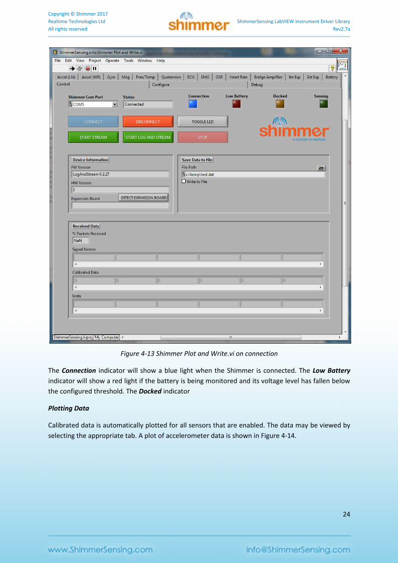
Shimmer Plot and Write.vi
Prior to reading this section the reader should have covered the section describing the Shimmer
Control and Configure.vi. The Shimmer Plot and Write.vi is a VI which, along with providing control
and configuration capabilities for the Shimmer, allows the user to acquire data from the Shimmer,
plot the data and write the data to a file.
Starting Shimmer Plot and Write.vi
The Shimmer Plot and Write.vi is located in the Examples folder of the ShimmerSensing Library. Open
the Shimmer Plot and Write.vi front panel and run the VI. The front panel of the Shimmer Plot and
Write.vi is as illustrated in Figure 4-13 and includes a number of tabs which the user can use to view
data during Streaming. It also includes an option to write data to a file.
Copyright © Shimmer 2017
Realtime Technologies Ltd ShimmerSensing LabVIEW Instrument Driver Library
All rights reserved Rev2.7a
24
Figure 4-13 Shimmer Plot and Write.vi on connection
The Connection indicator will show a blue light when the Shimmer is connected. The Low Battery
indicator will show a red light if the battery is being monitored and its voltage level has fallen below
the configured threshold. The Docked indicator
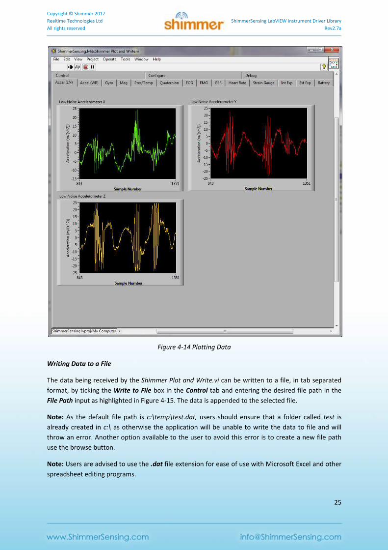
Plotting Data
Calibrated data is automatically plotted for all sensors that are enabled. The data may be viewed by
selecting the appropriate tab. A plot of accelerometer data is shown in Figure 4-14.
Copyright © Shimmer 2017
Realtime Technologies Ltd ShimmerSensing LabVIEW Instrument Driver Library
All rights reserved Rev2.7a
25
Figure 4-14 Plotting Data
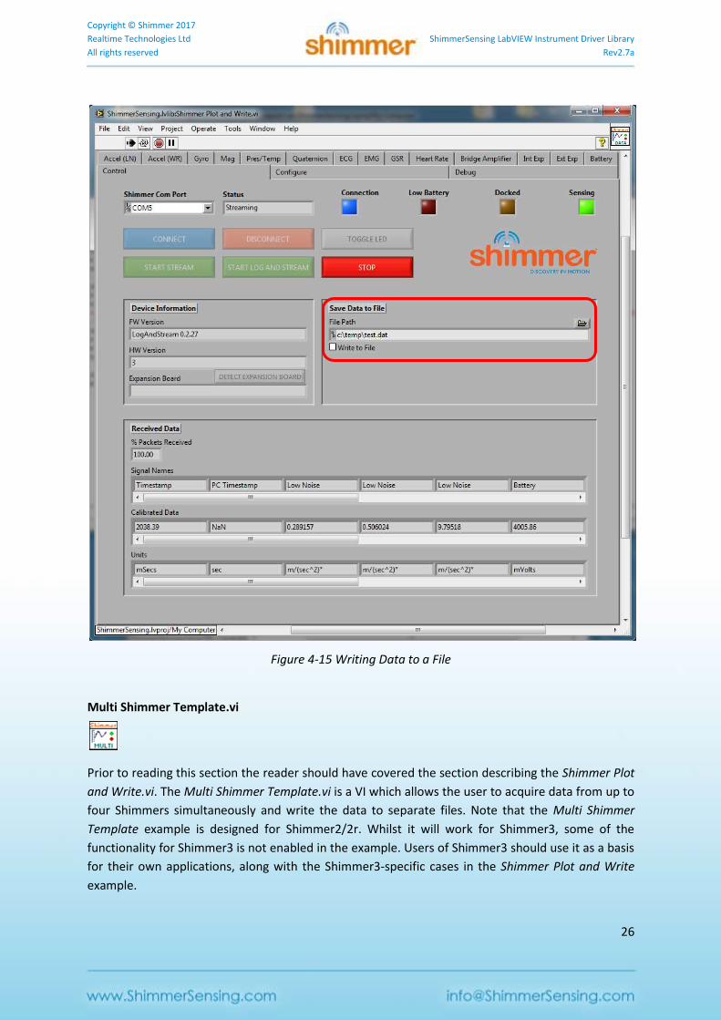
Writing Data to a File
The data being received by the Shimmer Plot and Write.vi can be written to a file, in tab separated
format, by ticking the Write to File box in the Control tab and entering the desired file path in the
File Path input as highlighted in Figure 4-15. The data is appended to the selected file.
Note: As the default file path is c:\temp\test.dat, users should ensure that a folder called test is
already created in c:\ as otherwise the application will be unable to write the data to file and will
throw an error. Another option available to the user to avoid this error is to create a new file path
use the browse button.
Note: Users are advised to use the .dat file extension for ease of use with Microsoft Excel and other
spreadsheet editing programs.
Copyright © Shimmer 2017
Realtime Technologies Ltd ShimmerSensing LabVIEW Instrument Driver Library
All rights reserved Rev2.7a
26
Figure 4-15 Writing Data to a File
Multi Shimmer Template.vi
Prior to reading this section the reader should have covered the section describing the Shimmer Plot
and Write.vi. The Multi Shimmer Template.vi is a VI which allows the user to acquire data from up to
four Shimmers simultaneously and write the data to separate files. Note that the Multi Shimmer
Template example is designed for Shimmer2/2r. Whilst it will work for Shimmer3, some of the
functionality for Shimmer3 is not enabled in the example. Users of Shimmer3 should use it as a basis
for their own applications, along with the Shimmer3-specific cases in the Shimmer Plot and Write
example.
Copyright © Shimmer 2017
Realtime Technologies Ltd ShimmerSensing LabVIEW Instrument Driver Library
All rights reserved Rev2.7a
27
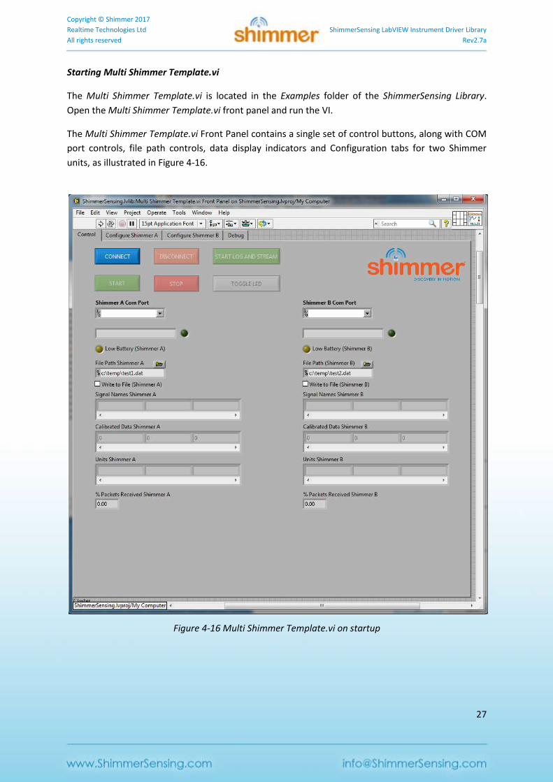
Starting Multi Shimmer Template.vi
The Multi Shimmer Template.vi is located in the Examples folder of the ShimmerSensing Library.
Open the Multi Shimmer Template.vi front panel and run the VI.
The Multi Shimmer Template.vi Front Panel contains a single set of control buttons, along with COM
port controls, file path controls, data display indicators and Configuration tabs for two Shimmer
units, as illustrated in Figure 4-16.
Figure 4-16 Multi Shimmer Template.vi on startup
Copyright © Shimmer 2017
Realtime Technologies Ltd ShimmerSensing LabVIEW Instrument Driver Library
All rights reserved Rev2.7a
28
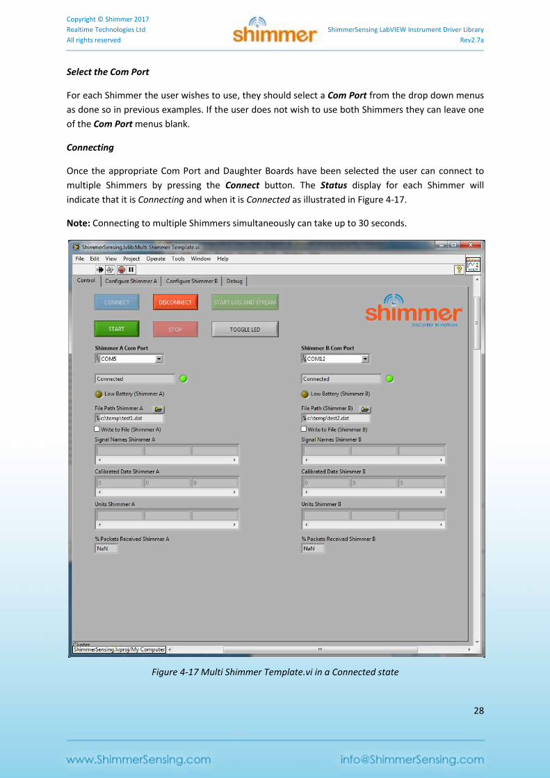
Select the Com Port
For each Shimmer the user wishes to use, they should select a Com Port from the drop down menus
as done so in previous examples. If the user does not wish to use both Shimmers they can leave one
of the Com Port menus blank.
Connecting
Once the appropriate Com Port and Daughter Boards have been selected the user can connect to
multiple Shimmers by pressing the Connect button. The Status display for each Shimmer will
indicate that it is Connecting and when it is Connected as illustrated in Figure 4-17.
Note: Connecting to multiple Shimmers simultaneously can take up to 30 seconds.
Figure 4-17 Multi Shimmer Template.vi in a Connected state
Copyright © Shimmer 2017
Realtime Technologies Ltd ShimmerSensing LabVIEW Instrument Driver Library
All rights reserved Rev2.7a
29
Configuring the Devices
Once Connected the user should then select the Configure Shimmer A or Configure Shimmer B tab, as
appropriate, to configure the device, as in the Shimmer Plot and Write example.
Streaming and Writing Data to File
If desired, the user should enter an appropriate file path for each Shimmer to write the data to a file.
Once the appropriate settings are correct, the user can start streaming data by pressing the Start
button. The Status display for each Shimmer will indicate when data has started streaming.
Note: If for some reason the Shimmer selected in Shimmer A fails to connect or fails to start
streaming the application will not display any streaming data. This is due to the fact that the event
based control in the VI is based on the Status of Shimmer A. To avoid such as scenario ensure that
the Status of Shimmer A is as expected before proceeding.
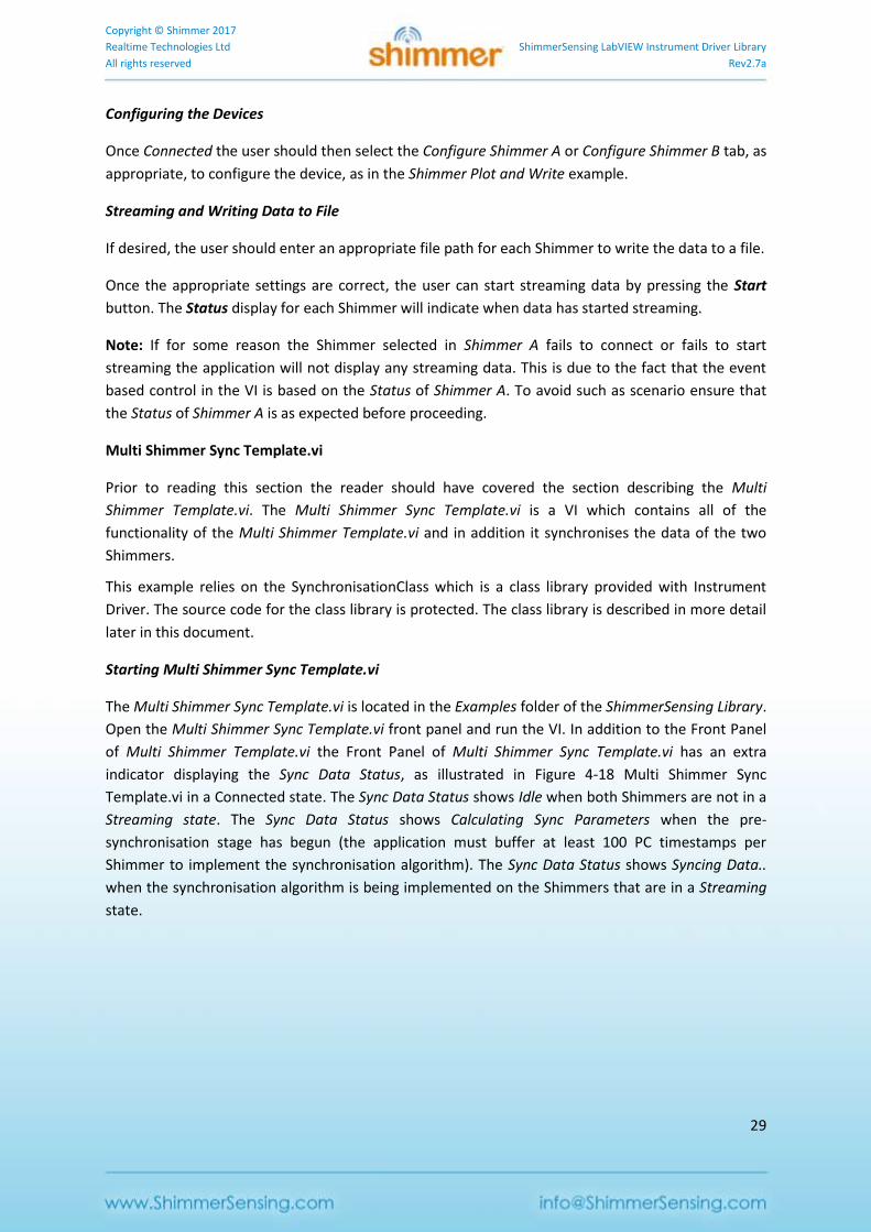
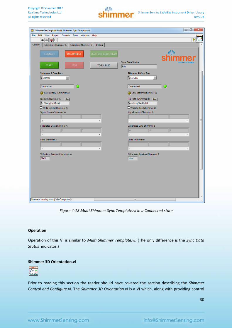
Multi Shimmer Sync Template.vi
Prior to reading this section the reader should have covered the section describing the Multi
Shimmer Template.vi. The Multi Shimmer Sync Template.vi is a VI which contains all of the
functionality of the Multi Shimmer Template.vi and in addition it synchronises the data of the two
Shimmers.
This example relies on the SynchronisationClass which is a class library provided with Instrument
Driver. The source code for the class library is protected. The class library is described in more detail
later in this document.
Starting Multi Shimmer Sync Template.vi
The Multi Shimmer Sync Template.vi is located in the Examples folder of the ShimmerSensing Library.
Open the Multi Shimmer Sync Template.vi front panel and run the VI. In addition to the Front Panel
of Multi Shimmer Template.vi the Front Panel of Multi Shimmer Sync Template.vi has an extra
indicator displaying the Sync Data Status, as illustrated in Figure 4-18 Multi Shimmer Sync
Template.vi in a Connected state. The Sync Data Status shows Idle when both Shimmers are not in a
Streaming state. The Sync Data Status shows Calculating Sync Parameters when the pre-
synchronisation stage has begun (the application must buffer at least 100 PC timestamps per
Shimmer to implement the synchronisation algorithm). The Sync Data Status shows Syncing Data..
when the synchronisation algorithm is being implemented on the Shimmers that are in a Streaming
state.
Copyright © Shimmer 2017
Realtime Technologies Ltd ShimmerSensing LabVIEW Instrument Driver Library
All rights reserved Rev2.7a
30
Figure 4-18 Multi Shimmer Sync Template.vi in a Connected state
Operation
Operation of this VI is similar to Multi Shimmer Template.vi. (The only difference is the Sync Data
Status indicator.)
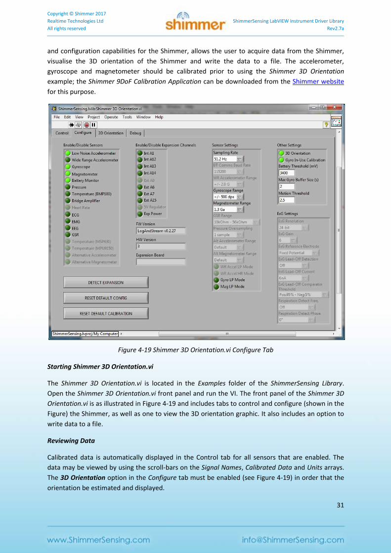
Shimmer 3D Orientation.vi
Prior to reading this section the reader should have covered the section describing the Shimmer
Control and Configure.vi. The Shimmer 3D Orientation.vi is a VI which, along with providing control
Copyright © Shimmer 2017
Realtime Technologies Ltd ShimmerSensing LabVIEW Instrument Driver Library
All rights reserved Rev2.7a
31
and configuration capabilities for the Shimmer, allows the user to acquire data from the Shimmer,
visualise the 3D orientation of the Shimmer and write the data to a file. The accelerometer,
gyroscope and magnetometer should be calibrated prior to using the Shimmer 3D Orientation
example; the Shimmer 9DoF Calibration Application can be downloaded from the Shimmer website
for this purpose.
Figure 4-19 Shimmer 3D Orientation.vi Configure Tab
Starting Shimmer 3D Orientation.vi
The Shimmer 3D Orientation.vi is located in the Examples folder of the ShimmerSensing Library.
Open the Shimmer 3D Orientation.vi front panel and run the VI. The front panel of the Shimmer 3D
Orientation.vi is as illustrated in Figure 4-19 and includes tabs to control and configure (shown in the
Figure) the Shimmer, as well as one to view the 3D orientation graphic. It also includes an option to
write data to a file.
Reviewing Data
Calibrated data is automatically displayed in the Control tab for all sensors that are enabled. The
data may be viewed by using the scroll-bars on the Signal Names, Calibrated Data and Units arrays.
The 3D Orientation option in the Configure tab must be enabled (see Figure 4-19) in order that the
orientation be estimated and displayed.
Copyright © Shimmer 2017
Realtime Technologies Ltd ShimmerSensing LabVIEW Instrument Driver Library
All rights reserved Rev2.7a
32
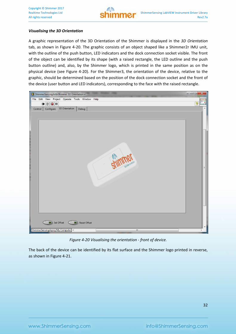
Visualising the 3D Orientation
A graphic representation of the 3D Orientation of the Shimmer is displayed in the 3D Orientation
tab, as shown in Figure 4-20. The graphic consists of an object shaped like a Shimmer2r IMU unit,
with the outline of the push button, LED indicators and the dock connection socket visible. The front
of the object can be identified by its shape (with a raised rectangle, the LED outline and the push
button outline) and, also, by the Shimmer logo, which is printed in the same position as on the
physical device (see Figure 4-20). For the Shimmer3, the orientation of the device, relative to the
graphic, should be determined based on the position of the dock connection socket and the front of
the device (user button and LED indicators), corresponding to the face with the raised rectangle.
Figure 4-20 Visualising the orientation - front of device.
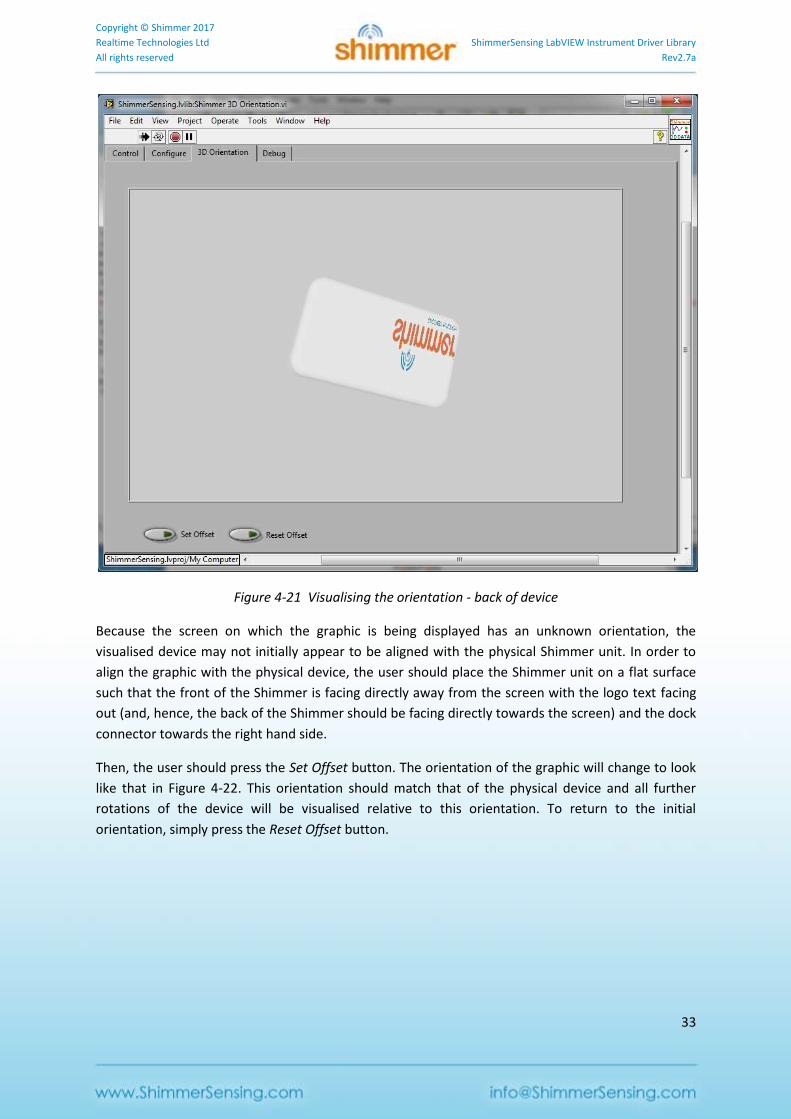
The back of the device can be identified by its flat surface and the Shimmer logo printed in reverse,
as shown in Figure 4-21.
Copyright © Shimmer 2017
Realtime Technologies Ltd ShimmerSensing LabVIEW Instrument Driver Library
All rights reserved Rev2.7a
33
Figure 4-21 Visualising the orientation - back of device
Because the screen on which the graphic is being displayed has an unknown orientation, the
visualised device may not initially appear to be aligned with the physical Shimmer unit. In order to
align the graphic with the physical device, the user should place the Shimmer unit on a flat surface
such that the front of the Shimmer is facing directly away from the screen with the logo text facing
out (and, hence, the back of the Shimmer should be facing directly towards the screen) and the dock
connector towards the right hand side.
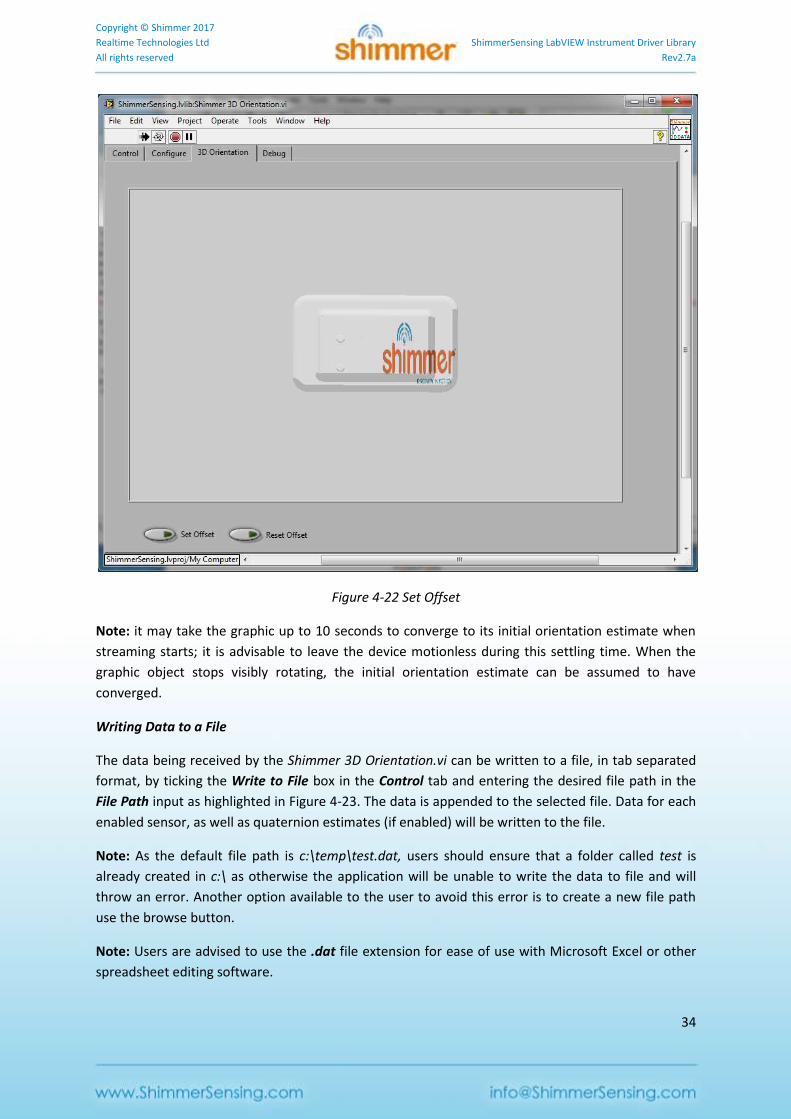
Then, the user should press the Set Offset button. The orientation of the graphic will change to look
like that in Figure 4-22. This orientation should match that of the physical device and all further
rotations of the device will be visualised relative to this orientation. To return to the initial
orientation, simply press the Reset Offset button.
Copyright © Shimmer 2017
Realtime Technologies Ltd ShimmerSensing LabVIEW Instrument Driver Library
All rights reserved Rev2.7a
34
Figure 4-22 Set Offset
Note: it may take the graphic up to 10 seconds to converge to its initial orientation estimate when
streaming starts; it is advisable to leave the device motionless during this settling time. When the
graphic object stops visibly rotating, the initial orientation estimate can be assumed to have
converged.
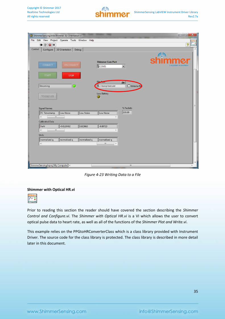
Writing Data to a File
The data being received by the Shimmer 3D Orientation.vi can be written to a file, in tab separated
format, by ticking the Write to File box in the Control tab and entering the desired file path in the
File Path input as highlighted in Figure 4-23. The data is appended to the selected file. Data for each
enabled sensor, as well as quaternion estimates (if enabled) will be written to the file.
Note: As the default file path is c:\temp\test.dat, users should ensure that a folder called test is
already created in c:\ as otherwise the application will be unable to write the data to file and will
throw an error. Another option available to the user to avoid this error is to create a new file path
use the browse button.
Note: Users are advised to use the .dat file extension for ease of use with Microsoft Excel or other
spreadsheet editing software.
Copyright © Shimmer 2017
Realtime Technologies Ltd ShimmerSensing LabVIEW Instrument Driver Library
All rights reserved Rev2.7a
35
Figure 4-23 Writing Data to a File
Shimmer with Optical HR.vi
Prior to reading this section the reader should have covered the section describing the Shimmer
Control and Configure.vi. The Shimmer with Optical HR.vi is a VI which allows the user to convert
optical pulse data to heart rate, as well as all of the functions of the Shimmer Plot and Write.vi.
This example relies on the PPGtoHRConverterClass which is a class library provided with Instrument
Driver. The source code for the class library is protected. The class library is described in more detail
later in this document.

Copyright © Shimmer 2017
Realtime Technologies Ltd ShimmerSensing LabVIEW Instrument Driver Library
All rights reserved Rev2.7a
36
Figure 4-24 Shimmer with Optical HR.vi Control Tab (Shimmer Connected)
Starting Shimmer with Optical HR.vi
The Shimmer with Optical HR.vi is located in the Examples folder of the ShimmerSensing Library.
Open the Shimmer with Optical HR.vi front panel and run the VI. The front panel of the VI is as
illustrated in Figure 4-24 and includes tabs to control and configure the Shimmer, as well as tabs to
view the output data. It also includes a Convert PPG file to HR tab, which can be used to convert
previously saved PPG data to heart rate.
Configuring the Shimmer
A Shimmer3 device with a GSR+ or PROTO3 Deluxe Expansion Board and an Optical Pulse Probe
attached to one of the 3.5mm jack connectors, can be used to capture Optical Pulse data in the form
of a photoplethysmogram (PPG) signal. In order to enable the Optical Pulse data, the relevant
Copyright © Shimmer 2017
Realtime Technologies Ltd ShimmerSensing LabVIEW Instrument Driver Library
All rights reserved Rev2.7a
37
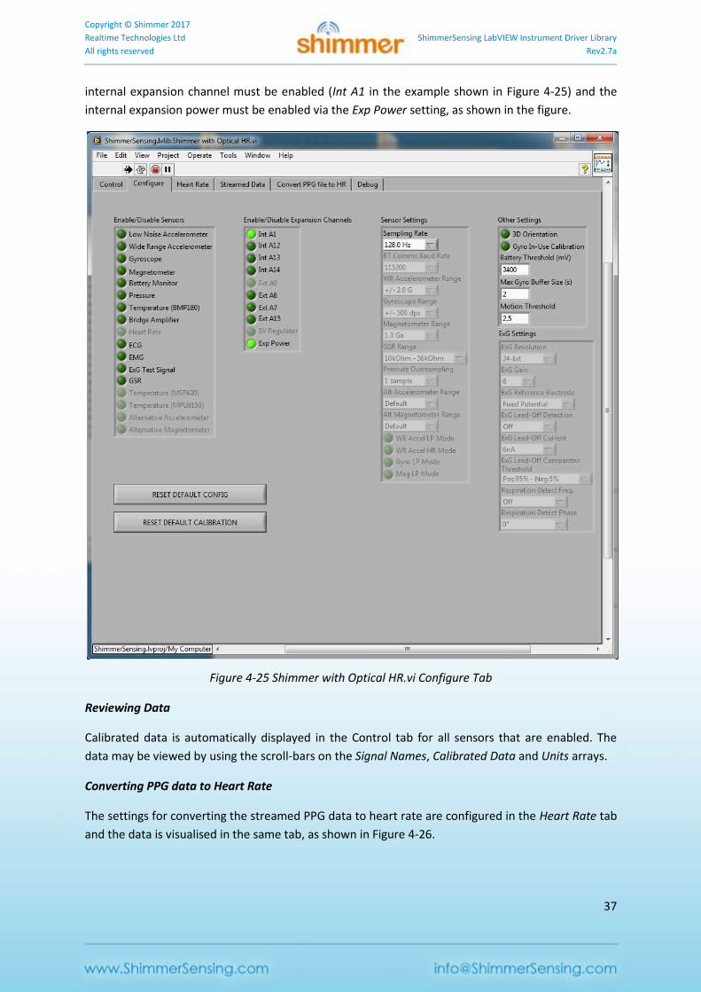
internal expansion channel must be enabled (Int A1 in the example shown in Figure 4-25) and the
internal expansion power must be enabled via the Exp Power setting, as shown in the figure.
Figure 4-25 Shimmer with Optical HR.vi Configure Tab
Reviewing Data
Calibrated data is automatically displayed in the Control tab for all sensors that are enabled. The
data may be viewed by using the scroll-bars on the Signal Names, Calibrated Data and Units arrays.
Converting PPG data to Heart Rate
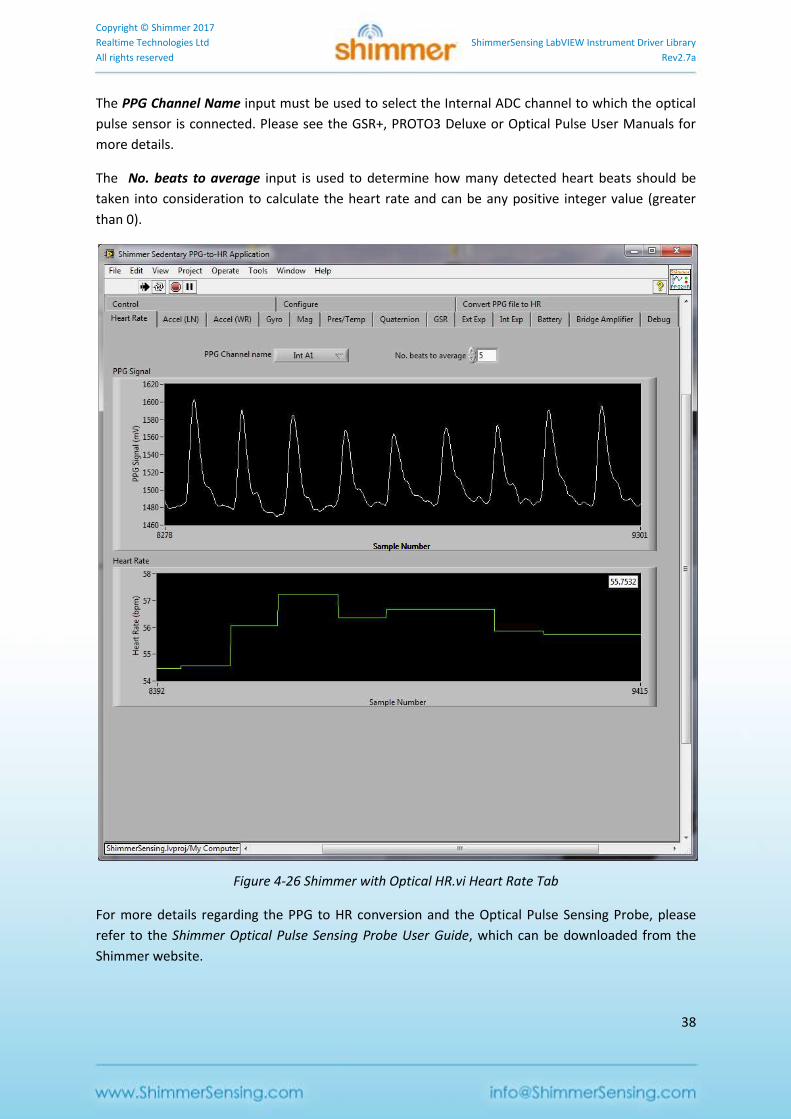
The settings for converting the streamed PPG data to heart rate are configured in the Heart Rate tab
and the data is visualised in the same tab, as shown in Figure 4-26.
Copyright © Shimmer 2017
Realtime Technologies Ltd ShimmerSensing LabVIEW Instrument Driver Library
All rights reserved Rev2.7a
38
The PPG Channel Name input must be used to select the Internal ADC channel to which the optical
pulse sensor is connected. Please see the GSR+, PROTO3 Deluxe or Optical Pulse User Manuals for
more details.
The No. beats to average input is used to determine how many detected heart beats should be
taken into consideration to calculate the heart rate and can be any positive integer value (greater
than 0).
Figure 4-26 Shimmer with Optical HR.vi Heart Rate Tab
For more details regarding the PPG to HR conversion and the Optical Pulse Sensing Probe, please
refer to the Shimmer Optical Pulse Sensing Probe User Guide, which can be downloaded from the
Shimmer website.

Copyright © Shimmer 2017
Realtime Technologies Ltd ShimmerSensing LabVIEW Instrument Driver Library
All rights reserved Rev2.7a
39
Writing Streamed Data to a File
The data being received by the Shimmer with Optical HR.vi can be written to a file, in tab separated
format, by ticking the Write to File box in the Control tab and entering the desired file path in the
File Path input as highlighted in Figure 4-27. The data is appended to the selected file. Data for each
enabled sensor, as well as HR estimates will be written to the file.
Note: As the default file path is c:\temp\test.dat, users should ensure that a folder called test is
already created in c:\ as otherwise the application will be unable to write the data to file and will
throw an error. Another option available to the user to avoid this error is to create a new file path
use the browse button.
Note: Users are advised to use the .dat file extension for ease of use with Microsoft Excel or other
spreadsheet editing software.
Figure 4-27 Writing Data to a File
Copyright © Shimmer 2017
Realtime Technologies Ltd ShimmerSensing LabVIEW Instrument Driver Library
All rights reserved Rev2.7a
40
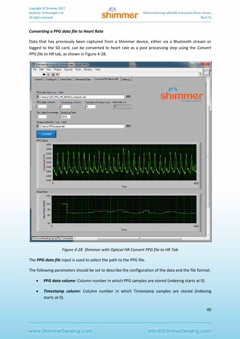
Converting a PPG data file to Heart Rate
Data that has previously been captured from a Shimmer device, either via a Bluetooth stream or
logged to the SD card, can be converted to heart rate as a post processing step using the Convert
PPG file to HR tab, as shown in Figure 4-28.
Figure 4-28 Shimmer with Optical HR Convert PPG file to HR Tab
The PPG data file input is used to select the path to the PPG file.
The following parameters should be set to describe the configuration of the data and the file format:
PPG data column: Column number in which PPG samples are stored (indexing starts at 0).
Timestamp column: Column number in which Timestamp samples are stored (indexing
starts at 0).
Copyright © Shimmer 2017
Realtime Technologies Ltd ShimmerSensing LabVIEW Instrument Driver Library
All rights reserved Rev2.7a
41
Note: The timestamps must be calibrated.
Number of header rows: number of rows containing header information; these rows will be
skipped by the processing.
delimiter: string representing the delimiter for the data file; e.g. "," (comma), "\t" (tab), "\s"
(space).
No. of beats to average: the number of consecutive detected pulses whose inter-beat-
intervals are to be averaged for heart rate estimation.
Sampling Rate: sampling rate at which the data was collected.
The Output data file input is used to select the path to which the processing output will be written.
The output file will contain the timestamps in the first column, the PPG data in the second column
and the estimated HR in the third column.
The Convert button should be clicked to carry out the PPG-to-HR conversion. When it is complete,
the PPG data and HR estimates will be displayed on the graphs.
Shimmer Advanced ECG.vi
Prior to reading this section the reader should have covered the section describing the Shimmer
Control and Configure.vi. The Shimmer Advanced ECG.vi is a VI which allows the user to convert ECG
data to heart rate, as well as all of the functions of the Shimmer Plot and Write.vi.
This example relies on the ECGtoHRConverterClass which is a class library provided with Instrument
Driver. The source code for the class library is protected. The class library is described in more detail
later in this document.
Copyright © Shimmer 2017
Realtime Technologies Ltd ShimmerSensing LabVIEW Instrument Driver Library
All rights reserved Rev2.7a
42
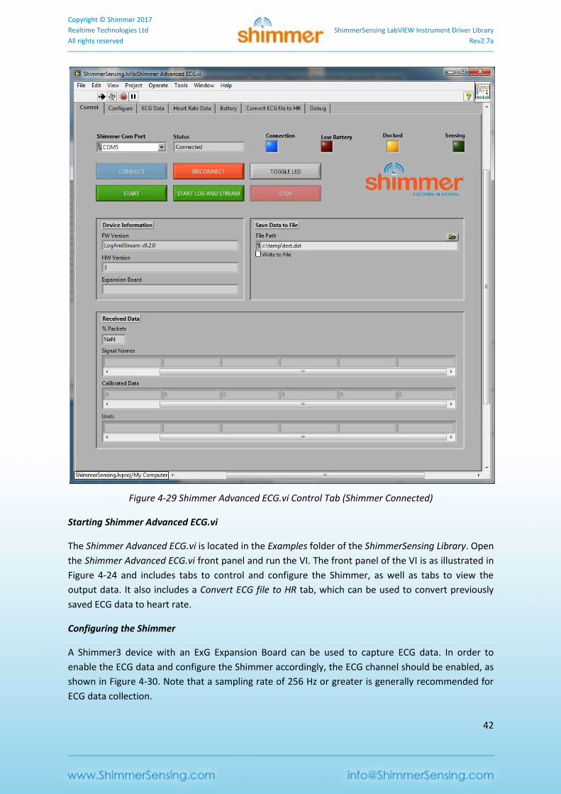
Figure 4-29 Shimmer Advanced ECG.vi Control Tab (Shimmer Connected)
Starting Shimmer Advanced ECG.vi
The Shimmer Advanced ECG.vi is located in the Examples folder of the ShimmerSensing Library. Open
the Shimmer Advanced ECG.vi front panel and run the VI. The front panel of the VI is as illustrated in
Figure 4-24 and includes tabs to control and configure the Shimmer, as well as tabs to view the
output data. It also includes a Convert ECG file to HR tab, which can be used to convert previously
saved ECG data to heart rate.
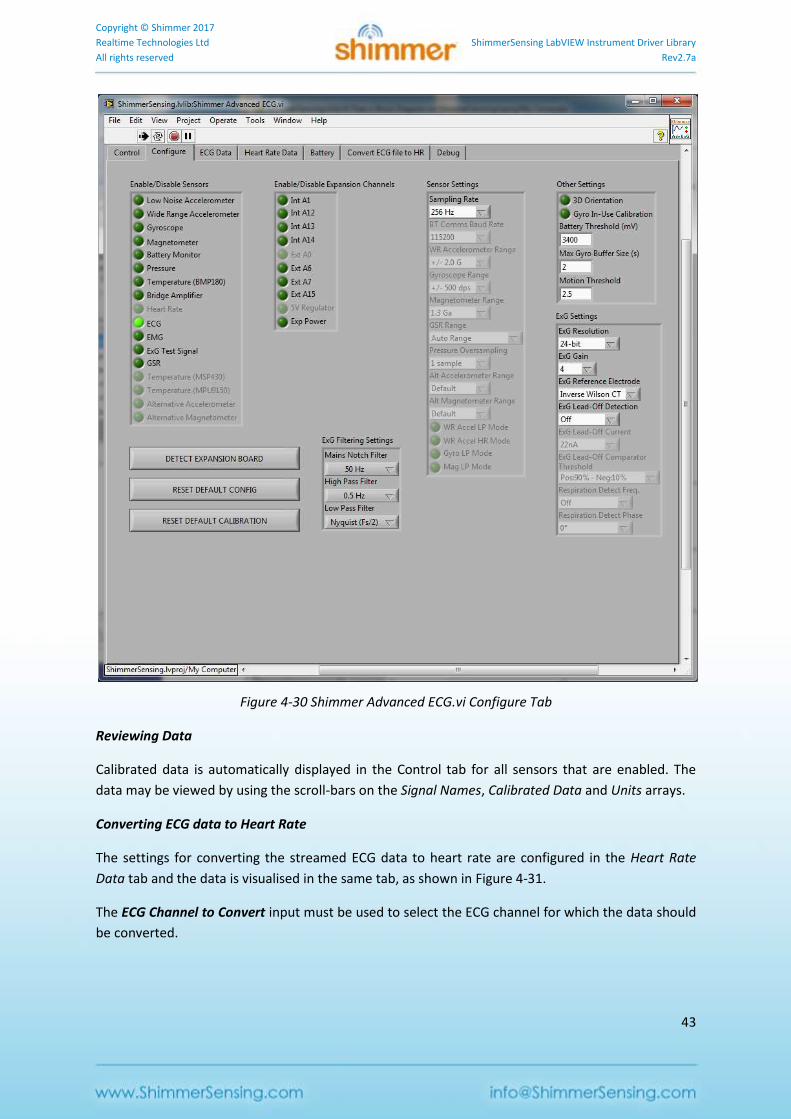
Configuring the Shimmer
A Shimmer3 device with an ExG Expansion Board can be used to capture ECG data. In order to
enable the ECG data and configure the Shimmer accordingly, the ECG channel should be enabled, as
shown in Figure 4-30. Note that a sampling rate of 256 Hz or greater is generally recommended for
ECG data collection.
Copyright © Shimmer 2017
Realtime Technologies Ltd ShimmerSensing LabVIEW Instrument Driver Library
All rights reserved Rev2.7a
43
Figure 4-30 Shimmer Advanced ECG.vi Configure Tab
Reviewing Data
Calibrated data is automatically displayed in the Control tab for all sensors that are enabled. The
data may be viewed by using the scroll-bars on the Signal Names, Calibrated Data and Units arrays.
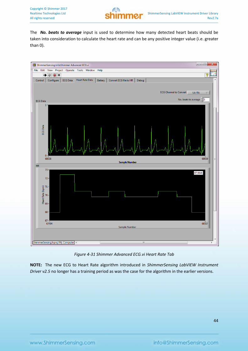
Converting ECG data to Heart Rate
The settings for converting the streamed ECG data to heart rate are configured in the Heart Rate
Data tab and the data is visualised in the same tab, as shown in Figure 4-31.
The ECG Channel to Convert input must be used to select the ECG channel for which the data should
be converted.
Copyright © Shimmer 2017
Realtime Technologies Ltd ShimmerSensing LabVIEW Instrument Driver Library
All rights reserved Rev2.7a
44
The No. beats to average input is used to determine how many detected heart beats should be
taken into consideration to calculate the heart rate and can be any positive integer value (i.e. greater
than 0).
Figure 4-31 Shimmer Advanced ECG.vi Heart Rate Tab
NOTE: The new ECG to Heart Rate algorithm introduced in ShimmerSensing LabVIEW Instrument
Driver v2.5 no longer has a training period as was the case for the algorithm in the earlier versions.
Copyright © Shimmer 2017
Realtime Technologies Ltd ShimmerSensing LabVIEW Instrument Driver Library
All rights reserved Rev2.7a
45
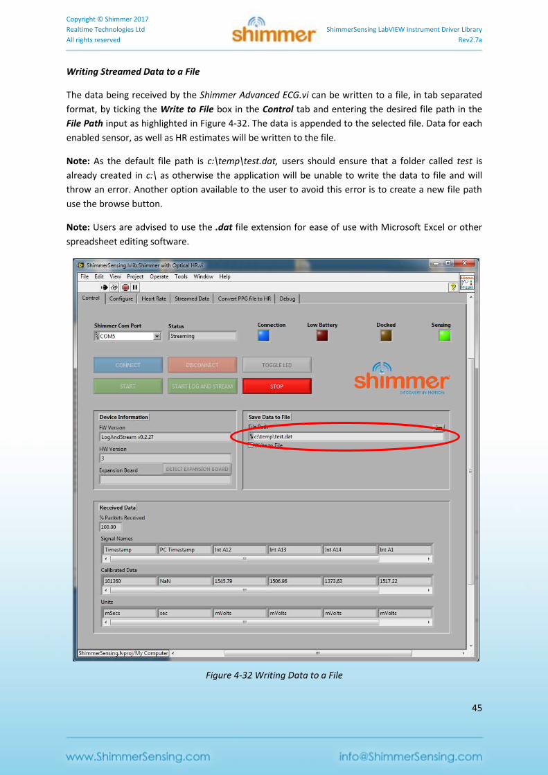
Writing Streamed Data to a File
The data being received by the Shimmer Advanced ECG.vi can be written to a file, in tab separated
format, by ticking the Write to File box in the Control tab and entering the desired file path in the
File Path input as highlighted in Figure 4-32. The data is appended to the selected file. Data for each
enabled sensor, as well as HR estimates will be written to the file.
Note: As the default file path is c:\temp\test.dat, users should ensure that a folder called test is
already created in c:\ as otherwise the application will be unable to write the data to file and will
throw an error. Another option available to the user to avoid this error is to create a new file path
use the browse button.
Note: Users are advised to use the .dat file extension for ease of use with Microsoft Excel or other
spreadsheet editing software.
Figure 4-32 Writing Data to a File
Copyright © Shimmer 2017
Realtime Technologies Ltd ShimmerSensing LabVIEW Instrument Driver Library
All rights reserved Rev2.7a
46
Converting an ECG data file to Heart Rate
Data that has previously been captured from a Shimmer device, either via a Bluetooth stream or
logged to the SD card, can be converted to heart rate as a post processing step using the Convert
ECG file to HR tab, as shown in Figure 4-33.
NOTE: In ShimmerSensing LabVIEW Instrument Driver v2.5 a new ECG to Heart Rate algorithm has
been introduced that does no longer have a training period as was the case for earlier versions.
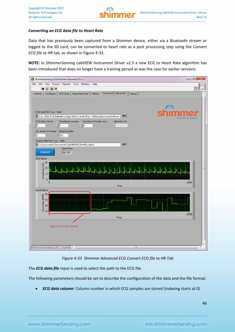
Figure 4-33 Shimmer Advanced ECG Convert ECG file to HR Tab
The ECG data file input is used to select the path to the ECG file.
The following parameters should be set to describe the configuration of the data and the file format:
ECG data column: Column number in which ECG samples are stored (indexing starts at 0).
Copyright © Shimmer 2017
Realtime Technologies Ltd ShimmerSensing LabVIEW Instrument Driver Library
All rights reserved Rev2.7a
47
Timestamp column: Column number in which Timestamp samples are stored (indexing
starts at 0).
Note: The timestamps must be calibrated.
Number of header rows: number of rows containing header information; these rows will be
skipped by the processing.
delimiter: string representing the delimiter for the data file; e.g. "," (comma), "\t" (tab), "\s"
(space).
No. of beats to average: the number of consecutive detected pulses whose inter-beat-
intervals are to be averaged for heart rate estimation.
Sampling Rate: sampling rate at which the data was collected.
The Output data file input is used to select the path to which the processing output will be written.
The output file will contain the timestamps in the first column, the ECG data in the second column
and the estimated HR in the third column.
The Convert button should be clicked to carry out the ECG-to-HR conversion. When it is complete,
the ECG data and HR estimates will be displayed on the graphs.
Example Applications Troubleshoot
When I use the Com Port drop down menu, the Com Port associated with my Shimmer isn’t listed?
1. Select the Refresh option listed in the Com Port drop down box on the GUI. If problem
persists go to step 2.
2. Verify the Com Port that your Shimmer is paired with is correct. This procedure is outlined in
the Shimmer User Manual.
When I press the Connect Button the Shimmer fails to connect?
1. Press the reset button on the Shimmer device and press the Connect button again. If
problem persists go to step 2.
2. Verify the Com Port that your Shimmer is paired with as outlined in the Shimmer User
Manual. If problem persists go to step 3.
3. Close the application and run it again. If problem persists go to step 4.
4. Ensure your Shimmer is functioning correctly by running another application with it. If it’s
not functioning correctly, please consult the Shimmer User Manual for further help.
Copyright © Shimmer 2017
Realtime Technologies Ltd ShimmerSensing LabVIEW Instrument Driver Library
All rights reserved Rev2.7a
48
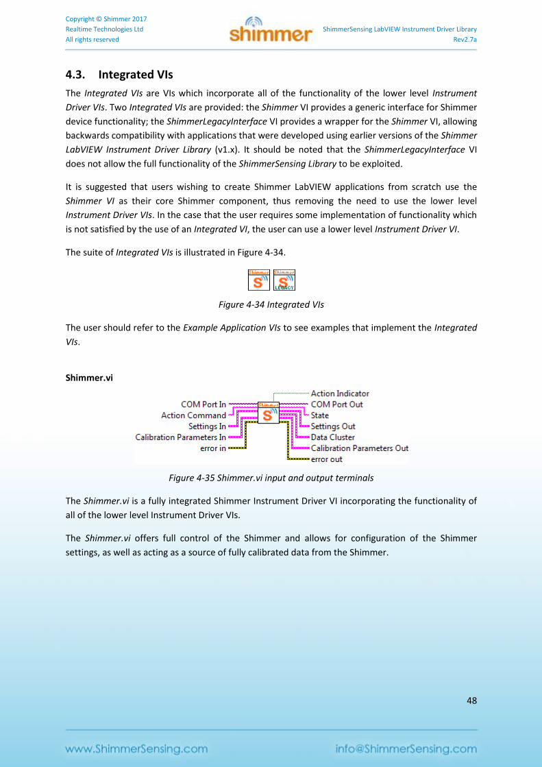
4.3. Integrated VIs
The Integrated VIs are VIs which incorporate all of the functionality of the lower level Instrument
Driver VIs. Two Integrated VIs are provided: the Shimmer VI provides a generic interface for Shimmer
device functionality; the ShimmerLegacyInterface VI provides a wrapper for the Shimmer VI, allowing
backwards compatibility with applications that were developed using earlier versions of the Shimmer
LabVIEW Instrument Driver Library (v1.x). It should be noted that the ShimmerLegacyInterface VI
does not allow the full functionality of the ShimmerSensing Library to be exploited.
It is suggested that users wishing to create Shimmer LabVIEW applications from scratch use the
Shimmer VI as their core Shimmer component, thus removing the need to use the lower level
Instrument Driver VIs. In the case that the user requires some implementation of functionality which
is not satisfied by the use of an Integrated VI, the user can use a lower level Instrument Driver VI.
The suite of Integrated VIs is illustrated in Figure 4-34.
Figure 4-34 Integrated VIs
The user should refer to the Example Application VIs to see examples that implement the Integrated
VIs.
Shimmer.vi
Figure 4-35 Shimmer.vi input and output terminals
The Shimmer.vi is a fully integrated Shimmer Instrument Driver VI incorporating the functionality of
all of the lower level Instrument Driver VIs.
The Shimmer.vi offers full control of the Shimmer and allows for configuration of the Shimmer
settings, as well as acting as a source of fully calibrated data from the Shimmer.
Copyright © Shimmer 2017
Realtime Technologies Ltd ShimmerSensing LabVIEW Instrument Driver Library
All rights reserved Rev2.7a
49
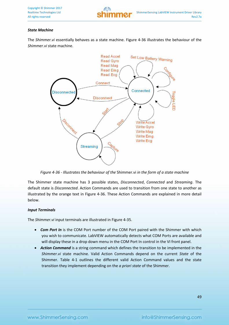
State Machine
The Shimmer.vi essentially behaves as a state machine. Figure 4-36 illustrates the behaviour of the
Shimmer.vi state machine.
Figure 4-36 - Illustrates the behaviour of the Shimmer.vi in the form of a state machine
The Shimmer state machine has 3 possible states, Disconnected, Connected and Streaming. The
default state is Disconnected. Action Commands are used to transition from one state to another as
illustrated by the orange text in Figure 4-36. These Action Commands are explained in more detail
below.
Input Terminals
The Shimmer.vi input terminals are illustrated in Figure 4-35.
Com Port In is the COM Port number of the COM Port paired with the Shimmer with which
you wish to communicate. LabVIEW automatically detects what COM Ports are available and
will display these in a drop down menu in the COM Port In control in the VI front panel.
Action Command is a string command which defines the transition to be implemented in the
Shimmer.vi state machine. Valid Action Commands depend on the current State of the
Shimmer. Table 4-1 outlines the different valid Action Command values and the state
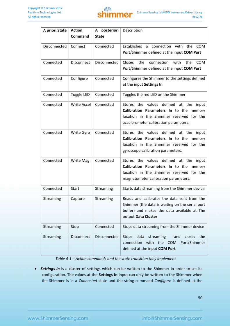
transition they implement depending on the a priori state of the Shimmer.
Copyright © Shimmer 2017
Realtime Technologies Ltd ShimmerSensing LabVIEW Instrument Driver Library
All rights reserved Rev2.7a
50
A priori State Action
Command
A posteriori
State
Description
Disconnected Connect Connected Establishes a connection with the COM
Port/Shimmer defined at the input COM Port
Connected Disconnect Disconnected Closes the connection with the COM
Port/Shimmer defined at the input COM Port
Connected Configure Connected Configures the Shimmer to the settings defined
at the input Settings In
Connected Toggle LED Connected Toggles the red LED on the Shimmer
Connected Write Accel Connected Stores the values defined at the input
Calibration Parameters In to the memory
location in the Shimmer reserved for the
accelerometer calibration parameters.
Connected Write Gyro Connected Stores the values defined at the input
Calibration Parameters In to the memory
location in the Shimmer reserved for the
gyroscope calibration parameters.
Connected Write Mag Connected Stores the values defined at the input
Calibration Parameters In to the memory
location in the Shimmer reserved for the
magnetometer calibration parameters.
Connected Start Streaming Starts data streaming from the Shimmer device
Streaming Capture Streaming Reads and calibrates the data sent from the
Shimmer (the data is waiting on the serial port
buffer) and makes the data available at The
output Data Cluster
Streaming Stop Connected Stops data streaming from the Shimmer device
Streaming Disconnect Disconnected Stops data streaming and closes the
connection with the COM Port/Shimmer
defined at the input COM Port
Table 4-1 – Action commands and the state transition they implement
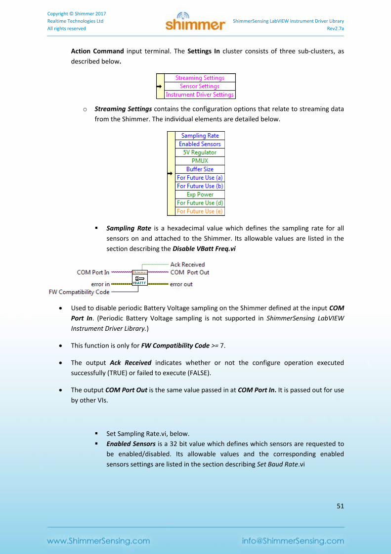
Settings In is a cluster of settings which can be written to the Shimmer in order to set its
configuration. The values at the Settings In input can only be written to the Shimmer when
the Shimmer is in a Connected state and the string command Configure is defined at the
Copyright © Shimmer 2017
Realtime Technologies Ltd ShimmerSensing LabVIEW Instrument Driver Library
All rights reserved Rev2.7a
51
Action Command input terminal. The Settings In cluster consists of three sub-clusters, as
described below.
o Streaming Settings contains the configuration options that relate to streaming data
from the Shimmer. The individual elements are detailed below.
Sampling Rate is a hexadecimal value which defines the sampling rate for all
sensors on and attached to the Shimmer. Its allowable values are listed in the
section describing the Disable VBatt Freq.vi
Used to disable periodic Battery Voltage sampling on the Shimmer defined at the input COM
Port In. (Periodic Battery Voltage sampling is not supported in ShimmerSensing LabVIEW
Instrument Driver Library.)
This function is only for FW Compatibility Code >= 7.
The output Ack Received indicates whether or not the configure operation executed
successfully (TRUE) or failed to execute (FALSE).
The output COM Port Out is the same value passed in at COM Port In. It is passed out for use
by other VIs.
Set Sampling Rate.vi, below.
Enabled Sensors is a 32 bit value which defines which sensors are requested to
be enabled/disabled. Its allowable values and the corresponding enabled
sensors settings are listed in the section describing Set Baud Rate.vi
Copyright © Shimmer 2017
Realtime Technologies Ltd ShimmerSensing LabVIEW Instrument Driver Library
All rights reserved Rev2.7a
52
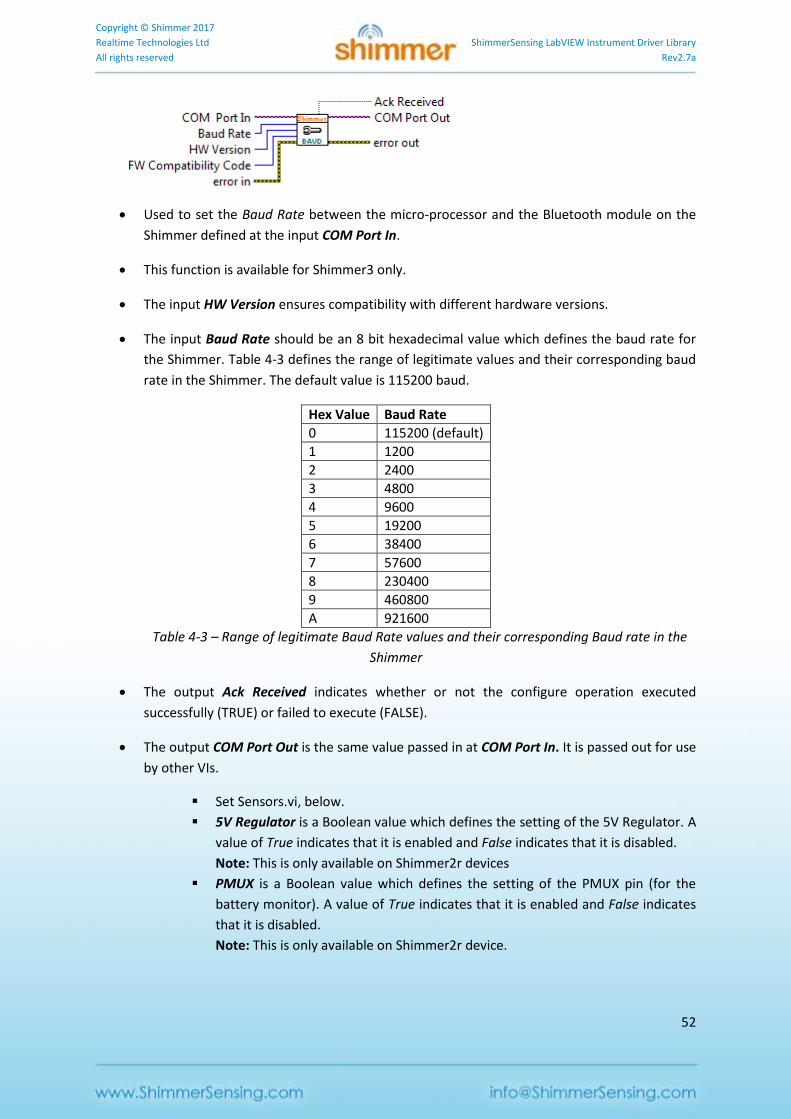
Used to set the Baud Rate between the micro-processor and the Bluetooth module on the
Shimmer defined at the input COM Port In.
This function is available for Shimmer3 only.
The input HW Version ensures compatibility with different hardware versions.
The input Baud Rate should be an 8 bit hexadecimal value which defines the baud rate for
the Shimmer. Table 4-3 defines the range of legitimate values and their corresponding baud
rate in the Shimmer. The default value is 115200 baud.
Hex Value Baud Rate
0 115200 (default)
1 1200
2 2400
3 4800
4 9600
5 19200
6 38400
7 57600
8 230400
9 460800
A 921600
Table 4-3 – Range of legitimate Baud Rate values and their corresponding Baud rate in the
Shimmer
The output Ack Received indicates whether or not the configure operation executed
successfully (TRUE) or failed to execute (FALSE).
The output COM Port Out is the same value passed in at COM Port In. It is passed out for use
by other VIs.
Set Sensors.vi, below.
5V Regulator is a Boolean value which defines the setting of the 5V Regulator. A
value of True indicates that it is enabled and False indicates that it is disabled.
Note: This is only available on Shimmer2r devices
PMUX is a Boolean value which defines the setting of the PMUX pin (for the
battery monitor). A value of True indicates that it is enabled and False indicates
that it is disabled.
Note: This is only available on Shimmer2r device.
Copyright © Shimmer 2017
Realtime Technologies Ltd ShimmerSensing LabVIEW Instrument Driver Library
All rights reserved Rev2.7a
53
Buffer Size is an integer value which specifies the number of samples that the
Shimmer will send in each data packet. Its value must be equal to 1 for
compatibility with the ShimmerSensing Library.
Exp Power is a Boolean value which defines the setting of the expansion board
power enable pin. A value of True indicates that the 3V connector on the
expansion board will be enabled when the device is streaming. A value of False
indicates that the 3V connector will be disabled.
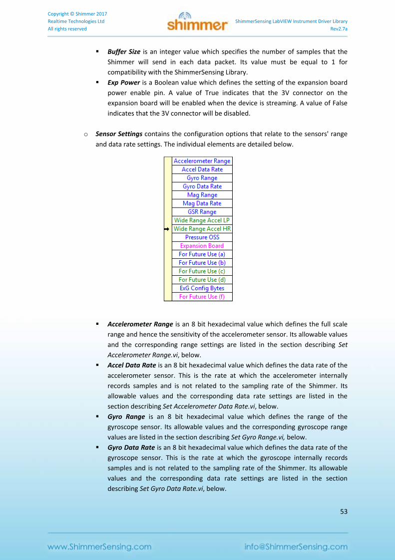
o Sensor Settings contains the configuration options that relate to the sensors' range
and data rate settings. The individual elements are detailed below.
Accelerometer Range is an 8 bit hexadecimal value which defines the full scale
range and hence the sensitivity of the accelerometer sensor. Its allowable values
and the corresponding range settings are listed in the section describing Set
Accelerometer Range.vi, below.
Accel Data Rate is an 8 bit hexadecimal value which defines the data rate of the
accelerometer sensor. This is the rate at which the accelerometer internally
records samples and is not related to the sampling rate of the Shimmer. Its
allowable values and the corresponding data rate settings are listed in the
section describing Set Accelerometer Data Rate.vi, below.
Gyro Range is an 8 bit hexadecimal value which defines the range of the
gyroscope sensor. Its allowable values and the corresponding gyroscope range
values are listed in the section describing Set Gyro Range.vi, below.
Gyro Data Rate is an 8 bit hexadecimal value which defines the data rate of the
gyroscope sensor. This is the rate at which the gyroscope internally records
samples and is not related to the sampling rate of the Shimmer. Its allowable
values and the corresponding data rate settings are listed in the section
describing Set Gyro Data Rate.vi, below.
Copyright © Shimmer 2017
Realtime Technologies Ltd ShimmerSensing LabVIEW Instrument Driver Library
All rights reserved Rev2.7a
54
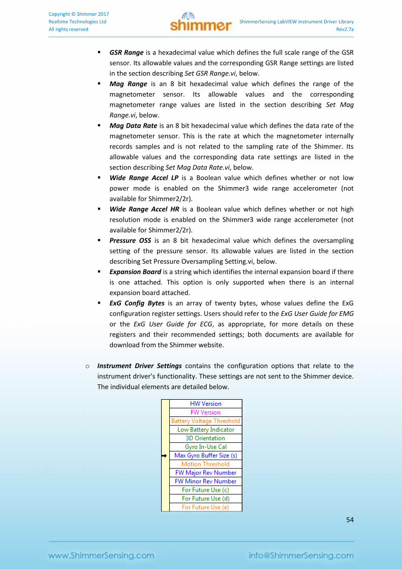
GSR Range is a hexadecimal value which defines the full scale range of the GSR
sensor. Its allowable values and the corresponding GSR Range settings are listed
in the section describing Set GSR Range.vi, below.
Mag Range is an 8 bit hexadecimal value which defines the range of the
magnetometer sensor. Its allowable values and the corresponding
magnetometer range values are listed in the section describing Set Mag
Range.vi, below.
Mag Data Rate is an 8 bit hexadecimal value which defines the data rate of the
magnetometer sensor. This is the rate at which the magnetometer internally
records samples and is not related to the sampling rate of the Shimmer. Its
allowable values and the corresponding data rate settings are listed in the
section describing Set Mag Data Rate.vi, below.
Wide Range Accel LP is a Boolean value which defines whether or not low
power mode is enabled on the Shimmer3 wide range accelerometer (not
available for Shimmer2/2r).
Wide Range Accel HR is a Boolean value which defines whether or not high
resolution mode is enabled on the Shimmer3 wide range accelerometer (not
available for Shimmer2/2r).
Pressure OSS is an 8 bit hexadecimal value which defines the oversampling
setting of the pressure sensor. Its allowable values are listed in the section
describing Set Pressure Oversampling Setting.vi, below.
Expansion Board is a string which identifies the internal expansion board if there
is one attached. This option is only supported when there is an internal
expansion board attached.
ExG Config Bytes is an array of twenty bytes, whose values define the ExG
configuration register settings. Users should refer to the ExG User Guide for EMG
or the ExG User Guide for ECG, as appropriate, for more details on these
registers and their recommended settings; both documents are available for
download from the Shimmer website.
o Instrument Driver Settings contains the configuration options that relate to the
instrument driver's functionality. These settings are not sent to the Shimmer device.
The individual elements are detailed below.
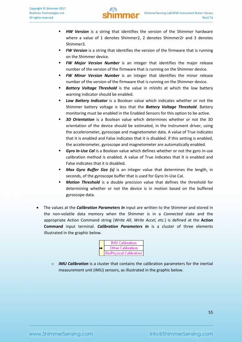
Copyright © Shimmer 2017
Realtime Technologies Ltd ShimmerSensing LabVIEW Instrument Driver Library
All rights reserved Rev2.7a
55
HW Version is a string that identifies the version of the Shimmer hardware
where a value of 1 denotes Shimmer2, 2 denotes Shimmer2r and 3 denotes
Shimmer3.
FW Version is a string that identifies the version of the firmware that is running
on the Shimmer device.
FW Major Version Number is an integer that identifies the major release
number of the version of the firmware that is running on the Shimmer device.
FW Minor Version Number is an integer that identifies the minor release
number of the version of the firmware that is running on the Shimmer device.
Battery Voltage Threshold is the value in mVolts at which the low battery
warning indicator should be enabled.
Low Battery Indicator is a Boolean value which indicates whether or not the
Shimmer battery voltage is less that the Battery Voltage Threshold. Battery
monitoring must be enabled in the Enabled Sensors for this option to be active.
3D Orientation is a Boolean value which determines whether or not the 3D
orientation of the device should be estimated, in the instrument driver, using
the accelerometer, gyroscope and magnetometer data. A value of True indicates
that it is enabled and False indicates that it is disabled. If this setting is enabled,
the accelerometer, gyroscope and magnetometer are automatically enabled.
Gyro In-Use Cal is a Boolean value which defines whether or not the gyro in-use
calibration method is enabled. A value of True indicates that it is enabled and
False indicates that it is disabled.
Max Gyro Buffer Size (s) is an integer value that determines the length, in
seconds, of the gyroscope buffer that is used for Gyro In-Use Cal.
Motion Threshold is a double precision value that defines the threshold for
determining whether or not the device is in motion based on the buffered
gyroscope data.
The values at the Calibration Parameters In input are written to the Shimmer and stored in
the non-volatile data memory when the Shimmer is in a Connected state and the
appropriate Action Command string (Write All, Write Accel, etc.) is defined at the Action
Command input terminal. Calibration Parameters In is a cluster of three elements
illustrated in the graphic below.
o IMU Calibration is a cluster that contains the calibration parameters for the inertial
measurement unit (IMU) sensors, as illustrated in the graphic below.
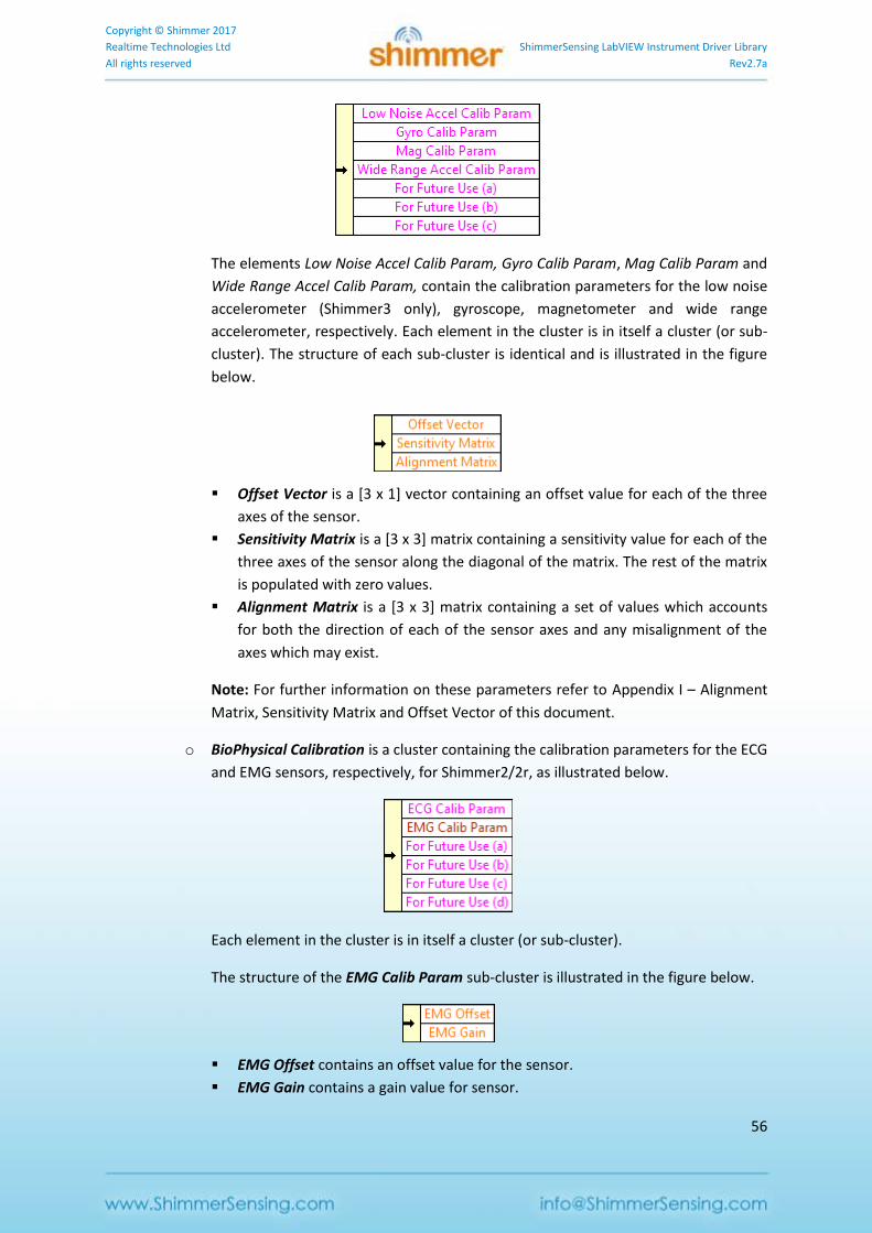
Copyright © Shimmer 2017
Realtime Technologies Ltd ShimmerSensing LabVIEW Instrument Driver Library
All rights reserved Rev2.7a
56
The elements Low Noise Accel Calib Param, Gyro Calib Param, Mag Calib Param and
Wide Range Accel Calib Param, contain the calibration parameters for the low noise
accelerometer (Shimmer3 only), gyroscope, magnetometer and wide range
accelerometer, respectively. Each element in the cluster is in itself a cluster (or sub-
cluster). The structure of each sub-cluster is identical and is illustrated in the figure
below.
Offset Vector is a [3 x 1] vector containing an offset value for each of the three
axes of the sensor.
Sensitivity Matrix is a [3 x 3] matrix containing a sensitivity value for each of the
three axes of the sensor along the diagonal of the matrix. The rest of the matrix
is populated with zero values.
Alignment Matrix is a [3 x 3] matrix containing a set of values which accounts
for both the direction of each of the sensor axes and any misalignment of the
axes which may exist.
Note: For further information on these parameters refer to Appendix I – Alignment
Matrix, Sensitivity Matrix and Offset Vector of this document.
o BioPhysical Calibration is a cluster containing the calibration parameters for the ECG
and EMG sensors, respectively, for Shimmer2/2r, as illustrated below.
Each element in the cluster is in itself a cluster (or sub-cluster).
The structure of the EMG Calib Param sub-cluster is illustrated in the figure below.
EMG Offset contains an offset value for the sensor.
EMG Gain contains a gain value for sensor.
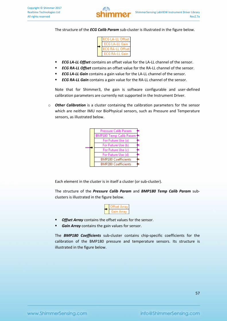
Copyright © Shimmer 2017
Realtime Technologies Ltd ShimmerSensing LabVIEW Instrument Driver Library
All rights reserved Rev2.7a
57
The structure of the ECG Calib Param sub-cluster is illustrated in the figure below.
ECG LA-LL Offset contains an offset value for the LA-LL channel of the sensor.
ECG RA-LL Offset contains an offset value for the RA-LL channel of the sensor.
ECG LA-LL Gain contains a gain value for the LA-LL channel of the sensor.
ECG RA-LL Gain contains a gain value for the RA-LL channel of the sensor.
Note that for Shimmer3, the gain is software configurable and user-defined
calibration parameters are currently not supported in the Instrument Driver.
o Other Calibration is a cluster containing the calibration parameters for the sensor
which are neither IMU nor BioPhysical sensors, such as Pressure and Temperature
sensors, as illustrated below.
Each element in the cluster is in itself a cluster (or sub-cluster).
The structure of the Pressure Calib Param and BMP180 Temp Calib Param sub-
clusters is illustrated in the figure below.
Offset Array contains the offset values for the sensor.
Gain Array contains the gain values for sensor.
The BMP180 Coefficients sub-cluster contains chip-specific coefficients for the
calibration of the BMP180 pressure and temperature sensors. Its structure is
illustrated in the figure below.
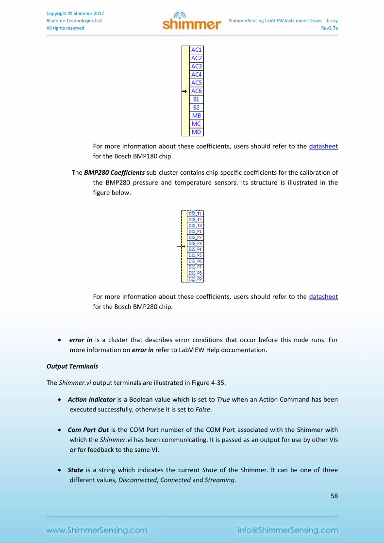
Copyright © Shimmer 2017
Realtime Technologies Ltd ShimmerSensing LabVIEW Instrument Driver Library
All rights reserved Rev2.7a
58
For more information about these coefficients, users should refer to the datasheet
for the Bosch BMP180 chip.
The BMP280 Coefficients sub-cluster contains chip-specific coefficients for the calibration of
the BMP280 pressure and temperature sensors. Its structure is illustrated in the
figure below.
For more information about these coefficients, users should refer to the datasheet
for the Bosch BMP280 chip.
error in is a cluster that describes error conditions that occur before this node runs. For
more information on error in refer to LabVIEW Help documentation.
Output Terminals
The Shimmer.vi output terminals are illustrated in Figure 4-35.
Action Indicator is a Boolean value which is set to True when an Action Command has been
executed successfully, otherwise it is set to False.
Com Port Out is the COM Port number of the COM Port associated with the Shimmer with
which the Shimmer.vi has been communicating. It is passed as an output for use by other VIs
or for feedback to the same VI.
State is a string which indicates the current State of the Shimmer. It can be one of three
different values, Disconnected, Connected and Streaming.
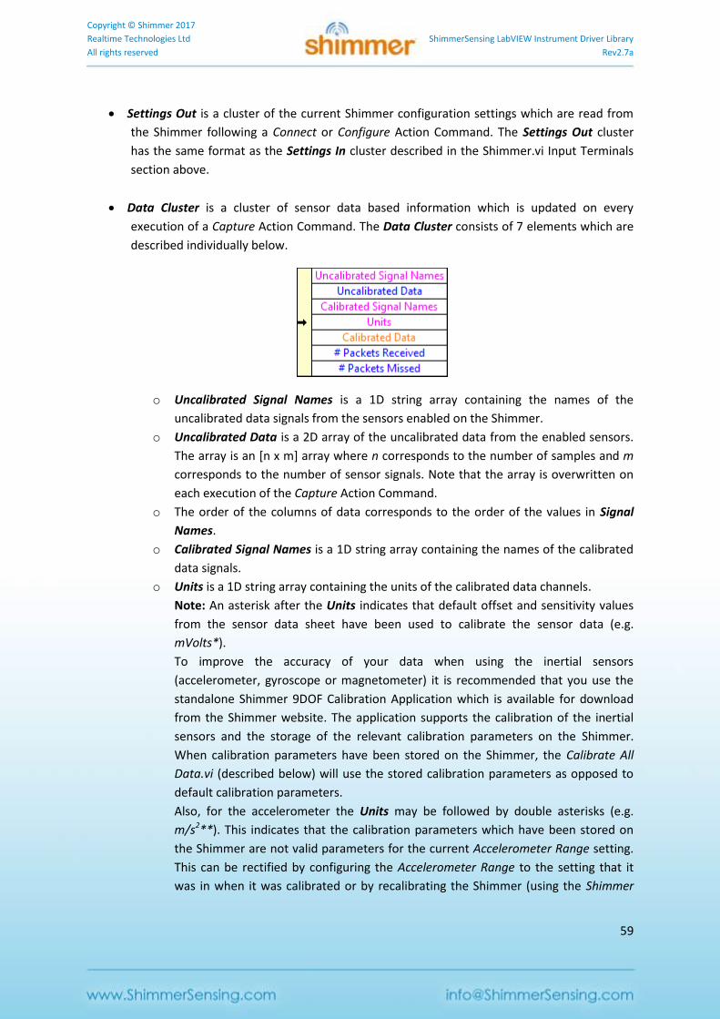
Copyright © Shimmer 2017
Realtime Technologies Ltd ShimmerSensing LabVIEW Instrument Driver Library
All rights reserved Rev2.7a
59
Settings Out is a cluster of the current Shimmer configuration settings which are read from
the Shimmer following a Connect or Configure Action Command. The Settings Out cluster
has the same format as the Settings In cluster described in the Shimmer.vi Input Terminals
section above.
Data Cluster is a cluster of sensor data based information which is updated on every
execution of a Capture Action Command. The Data Cluster consists of 7 elements which are
described individually below.
o Uncalibrated Signal Names is a 1D string array containing the names of the
uncalibrated data signals from the sensors enabled on the Shimmer.
o Uncalibrated Data is a 2D array of the uncalibrated data from the enabled sensors.
The array is an [n x m] array where n corresponds to the number of samples and m
corresponds to the number of sensor signals. Note that the array is overwritten on
each execution of the Capture Action Command.
o The order of the columns of data corresponds to the order of the values in Signal
Names.
o Calibrated Signal Names is a 1D string array containing the names of the calibrated
data signals.
o Units is a 1D string array containing the units of the calibrated data channels.
Note: An asterisk after the Units indicates that default offset and sensitivity values
from the sensor data sheet have been used to calibrate the sensor data (e.g.
mVolts*).
To improve the accuracy of your data when using the inertial sensors
(accelerometer, gyroscope or magnetometer) it is recommended that you use the
standalone Shimmer 9DOF Calibration Application which is available for download
from the Shimmer website. The application supports the calibration of the inertial
sensors and the storage of the relevant calibration parameters on the Shimmer.
When calibration parameters have been stored on the Shimmer, the Calibrate All
Data.vi (described below) will use the stored calibration parameters as opposed to
default calibration parameters.
Also, for the accelerometer the Units may be followed by double asterisks (e.g.
m/s2**). This indicates that the calibration parameters which have been stored on
the Shimmer are not valid parameters for the current Accelerometer Range setting.
This can be rectified by configuring the Accelerometer Range to the setting that it
was in when it was calibrated or by recalibrating the Shimmer (using the Shimmer
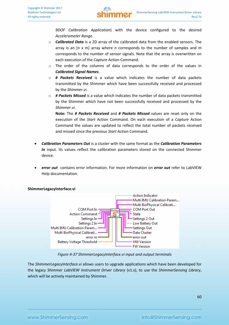
Copyright © Shimmer 2017
Realtime Technologies Ltd ShimmerSensing LabVIEW Instrument Driver Library
All rights reserved Rev2.7a
60
9DOF Calibration Application) with the device configured to the desired
Accelerometer Range.
o Calibrated Data is a 2D array of the calibrated data from the enabled sensors. The
array is an [n x m] array where n corresponds to the number of samples and m
corresponds to the number of sensor signals. Note that the array is overwritten on
each execution of the Capture Action Command.
o The order of the columns of data corresponds to the order of the values in
Calibrated Signal Names.
o # Packets Received is a value which indicates the number of data packets
transmitted by the Shimmer which have been successfully received and processed
by the Shimmer.vi.
o # Packets Missed is a value which indicates the number of data packets transmitted
by the Shimmer which have not been successfully received and processed by the
Shimmer.vi.
Note: The # Packets Received and # Packets Missed values are reset only on the
execution of the Start Action Command. On each execution of a Capture Action
Command the values are updated to reflect the total number of packets received
and missed since the previous Start Action Command.
Calibration Parameters Out is a cluster with the same format as the Calibration Parameters
In input. Its values reflect the calibration parameters stored on the connected Shimmer
device.
error out contains error information. For more information on error out refer to LabVIEW
Help documentation.
ShimmerLegacyInterface.vi
Figure 4-37 ShimmerLegacyInterface.vi input and output terminals
The ShimmerLegacyInterface.vi allows users to upgrade applications which have been developed for
the legacy Shimmer LabVIEW Instrument Driver Library (v1.x), to use the ShimmerSensing Library,
which will be actively maintained by Shimmer.

Copyright © Shimmer 2017
Realtime Technologies Ltd ShimmerSensing LabVIEW Instrument Driver Library
All rights reserved Rev2.7a
61
The ShimmerLegacyInterface.vi has the same interface as the legacy Shimmer.vi and, thus, a direct
substitution can be made.
For more detail describing each of the inputs and outputs of the ShimmerLegacyInterface.vi, the user
should refer to the documentation of the legacy instrument driver which has been previously used
for development.
Please note that, whilst the legacy interface will work with Shimmer2, Shimmer2r and Shimmer3
hardware, the full feature set of Shimmer3 cannot be exploited without fully upgrading to the
ShimmerSensing Library (i.e. using the Shimmer.vi, described above).
The main differences between the legacy Shimmer Library and the current ShimmerSensing Library
involve the Settings and Calibration clusters. The new structure of both of these clusters has been
described in detail in the previous section describing the Shimmer.vi integrated VI.
Any user who is familiar with the legacy Shimmer Library will clearly see that the new structure has
been designed to incorporate the growing number of configuration options that have come from
hardware, firmware and software improvements, in a streamlined way, that eliminates the
requirement for a growing number of input and output terminals in the VIs of the Instrument Driver.
The Settings cluster of the ShimmerSensing Library combines the Settings and Settings 2 clusters of
the legacy Shimmer Library along with other important parameters, needed for execution of the
instrument driver. Placeholders have also been added to allow for future developments without the
need for redesign of the VI interfaces.
The Calibration Parameters cluster of the ShimmerSensing Library combines the Multi IMU
Calibration Parameters and Multi BioPhysical Calibration Parameters clusters of the legacy Shimmer
Library along with calibration parameters for additional sensors that were not available on hardware
prior to Shimmer3. Once again, placeholders have also been added to allow for future developments
without the need for redesign of the VI interfaces.
4.4. Instrument Driver VIs
The Instrument Driver VIs are the lowest level VIs in the ShimmerSensing Library and may be used to
interface with the Shimmer. They are illustrated in Figure 4-38 where they are divided into a number
of different categories based on their core functionality. The VIs in each category are described in
more detail below.
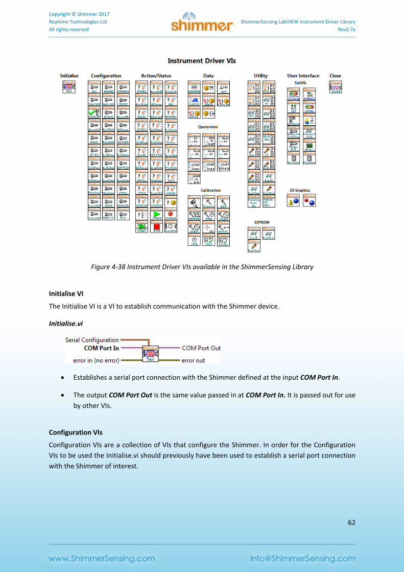
Copyright © Shimmer 2017
Realtime Technologies Ltd ShimmerSensing LabVIEW Instrument Driver Library
All rights reserved Rev2.7a
62
Figure 4-38 Instrument Driver VIs available in the ShimmerSensing Library
Initialise VI
The Initialise VI is a VI to establish communication with the Shimmer device.
Initialise.vi
Establishes a serial port connection with the Shimmer defined at the input COM Port In.
The output COM Port Out is the same value passed in at COM Port In. It is passed out for use
by other VIs.
Configuration VIs
Configuration VIs are a collection of VIs that configure the Shimmer. In order for the Configuration
VIs to be used the Initialise.vi should previously have been used to establish a serial port connection
with the Shimmer of interest.
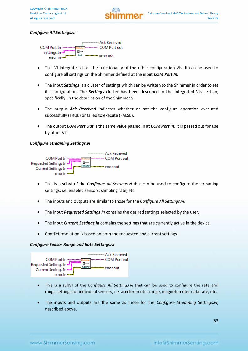
Copyright © Shimmer 2017
Realtime Technologies Ltd ShimmerSensing LabVIEW Instrument Driver Library
All rights reserved Rev2.7a
63
Configure All Settings.vi
This VI integrates all of the functionality of the other configuration VIs. It can be used to
configure all settings on the Shimmer defined at the input COM Port In.
The input Settings is a cluster of settings which can be written to the Shimmer in order to set
its configuration. The Settings cluster has been described in the Integrated VIs section,
specifically, in the description of the Shimmer.vi.
The output Ack Received indicates whether or not the configure operation executed
successfully (TRUE) or failed to execute (FALSE).
The output COM Port Out is the same value passed in at COM Port In. It is passed out for use
by other VIs.
Configure Streaming Settings.vi
This is a subVI of the Configure All Settings.vi that can be used to configure the streaming
settings; i.e. enabled sensors, sampling rate, etc.
The inputs and outputs are similar to those for the Configure All Settings.vi.
The input Requested Settings In contains the desired settings selected by the user.
The input Current Settings In contains the settings that are currently active in the device.
Conflict resolution is based on both the requested and current settings.
Configure Sensor Range and Rate Settings.vi
This is a subVI of the Configure All Settings.vi that can be used to configure the rate and
range settings for individual sensors; i.e. accelerometer range, magnetometer data rate, etc.
The inputs and outputs are the same as those for the Configure Streaming Settings.vi,
described above.
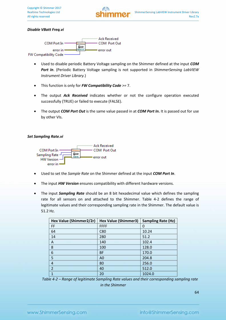
Copyright © Shimmer 2017
Realtime Technologies Ltd ShimmerSensing LabVIEW Instrument Driver Library
All rights reserved Rev2.7a
64
Disable VBatt Freq.vi
Used to disable periodic Battery Voltage sampling on the Shimmer defined at the input COM
Port In. (Periodic Battery Voltage sampling is not supported in ShimmerSensing LabVIEW
Instrument Driver Library.)
This function is only for FW Compatibility Code >= 7.
The output Ack Received indicates whether or not the configure operation executed
successfully (TRUE) or failed to execute (FALSE).
The output COM Port Out is the same value passed in at COM Port In. It is passed out for use
by other VIs.
Set Sampling Rate.vi
Used to set the Sample Rate on the Shimmer defined at the input COM Port In.
The input HW Version ensures compatibility with different hardware versions.
The input Sampling Rate should be an 8 bit hexadecimal value which defines the sampling
rate for all sensors on and attached to the Shimmer. Table 4-2 defines the range of
legitimate values and their corresponding sampling rate in the Shimmer. The default value is
51.2 Hz.
Hex Value (Shimmer2/2r) Hex Value (Shimmer3) Sampling Rate (Hz)
FF FFFF 0
64 C80 10.24
14 280 51.2
A 140 102.4
8 100 128.0
6 BF 170.0
5 A0 204.8
4 80 256.0
2 40 512.0
1 20 1024.0
Table 4-2 – Range of legitimate Sampling Rate values and their corresponding sampling rate
in the Shimmer
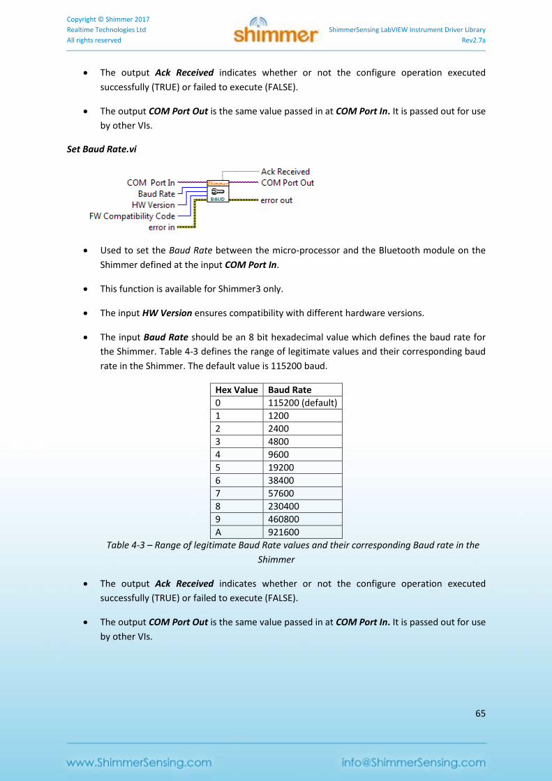
Copyright © Shimmer 2017
Realtime Technologies Ltd ShimmerSensing LabVIEW Instrument Driver Library
All rights reserved Rev2.7a
65
The output Ack Received indicates whether or not the configure operation executed
successfully (TRUE) or failed to execute (FALSE).
The output COM Port Out is the same value passed in at COM Port In. It is passed out for use
by other VIs.
Set Baud Rate.vi
Used to set the Baud Rate between the micro-processor and the Bluetooth module on the
Shimmer defined at the input COM Port In.
This function is available for Shimmer3 only.
The input HW Version ensures compatibility with different hardware versions.
The input Baud Rate should be an 8 bit hexadecimal value which defines the baud rate for
the Shimmer. Table 4-3 defines the range of legitimate values and their corresponding baud
rate in the Shimmer. The default value is 115200 baud.
Hex Value Baud Rate
0 115200 (default)
1 1200
2 2400
3 4800
4 9600
5 19200
6 38400
7 57600
8 230400
9 460800
A 921600
Table 4-3 – Range of legitimate Baud Rate values and their corresponding Baud rate in the
Shimmer
The output Ack Received indicates whether or not the configure operation executed
successfully (TRUE) or failed to execute (FALSE).
The output COM Port Out is the same value passed in at COM Port In. It is passed out for use
by other VIs.
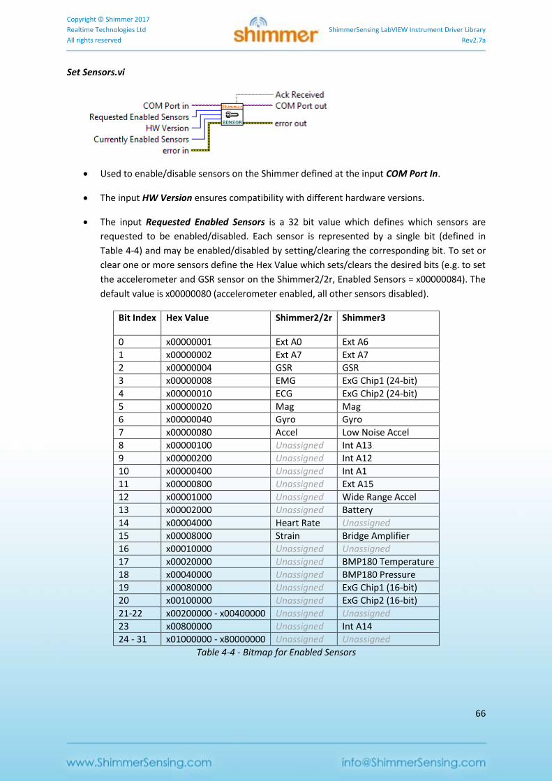
Copyright © Shimmer 2017
Realtime Technologies Ltd ShimmerSensing LabVIEW Instrument Driver Library
All rights reserved Rev2.7a
66
Set Sensors.vi
Used to enable/disable sensors on the Shimmer defined at the input COM Port In.
The input HW Version ensures compatibility with different hardware versions.
The input Requested Enabled Sensors is a 32 bit value which defines which sensors are
requested to be enabled/disabled. Each sensor is represented by a single bit (defined in
Table 4-4) and may be enabled/disabled by setting/clearing the corresponding bit. To set or
clear one or more sensors define the Hex Value which sets/clears the desired bits (e.g. to set
the accelerometer and GSR sensor on the Shimmer2/2r, Enabled Sensors = x00000084). The
default value is x00000080 (accelerometer enabled, all other sensors disabled).
Bit Index Hex Value Shimmer2/2r Shimmer3
0 x00000001 Ext A0 Ext A6
1 x00000002 Ext A7 Ext A7
2 x00000004 GSR GSR
3 x00000008 EMG ExG Chip1 (24-bit)
4 x00000010 ECG ExG Chip2 (24-bit)
5 x00000020 Mag Mag
6 x00000040 Gyro Gyro
7 x00000080 Accel Low Noise Accel
8 x00000100 Unassigned Int A13
9 x00000200 Unassigned Int A12
10 x00000400 Unassigned Int A1
11 x00000800 Unassigned Ext A15
12 x00001000 Unassigned Wide Range Accel
13 x00002000 Unassigned Battery
14 x00004000 Heart Rate Unassigned
15 x00008000 Strain Bridge Amplifier
16 x00010000 Unassigned Unassigned
17 x00020000 Unassigned BMP180 Temperature
18 x00040000 Unassigned BMP180 Pressure
19 x00080000 Unassigned ExG Chip1 (16-bit)
20 x00100000 Unassigned ExG Chip2 (16-bit)
21-22 x00200000 - x00400000 Unassigned Unassigned
23 x00800000 Unassigned Int A14
24 - 31 x01000000 - x80000000 Unassigned Unassigned
Table 4-4 - Bitmap for Enabled Sensors
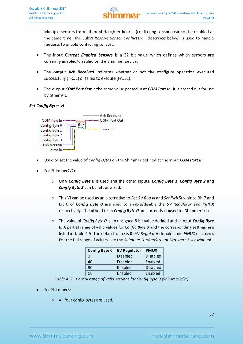
Copyright © Shimmer 2017
Realtime Technologies Ltd ShimmerSensing LabVIEW Instrument Driver Library
All rights reserved Rev2.7a
67
Multiple sensors from different daughter boards (conflicting sensors) cannot be enabled at
the same time. The SubVI Resolve Sensor Conflicts.vi (described below) is used to handle
requests to enable conflicting sensors.
The input Current Enabled Sensors is a 32 bit value which defines which sensors are
currently enabled/disabled on the Shimmer device.
The output Ack Received indicates whether or not the configure operation executed
successfully (TRUE) or failed to execute (FALSE).
The output COM Port Out is the same value passed in at COM Port In. It is passed out for use
by other VIs.
Set Config Bytes.vi
Used to set the value of Config Bytes on the Shimmer defined at the input COM Port In.
For Shimmer2/2r:
o Only Config Byte 0 is used and the other inputs, Config Byte 1, Config Byte 2 and
Config Byte 3 can be left unwired.
o This VI can be used as an alternative to Set 5V Reg.vi and Set PMUX.vi since Bit 7 and
Bit 6 of Config Byte 0 are used to enable/disable the 5V Regulator and PMUX
respectively. The other bits in Config Byte 0 are currently unused for Shimmer2/2r.
o The value of Config Byte 0 is an unsigned 8 bit value defined at the input Config Byte
0. A partial range of valid values for Config Byte 0 and the corresponding settings are
listed in Table 4-5. The default value is 0 (5V Regulator disabled and PMUX disabled).
For the full range of values, see the Shimmer LogAndStream Firmware User Manual.
Config Byte 0 5V Regulator PMUX
0 Disabled Disabled
40 Disabled Enabled
80 Enabled Disabled
C0 Enabled Enabled
Table 4-5 – Partial range of valid settings for Config Byte 0 (Shimmer2/2r)
For Shimmer3:
o All four config bytes are used.
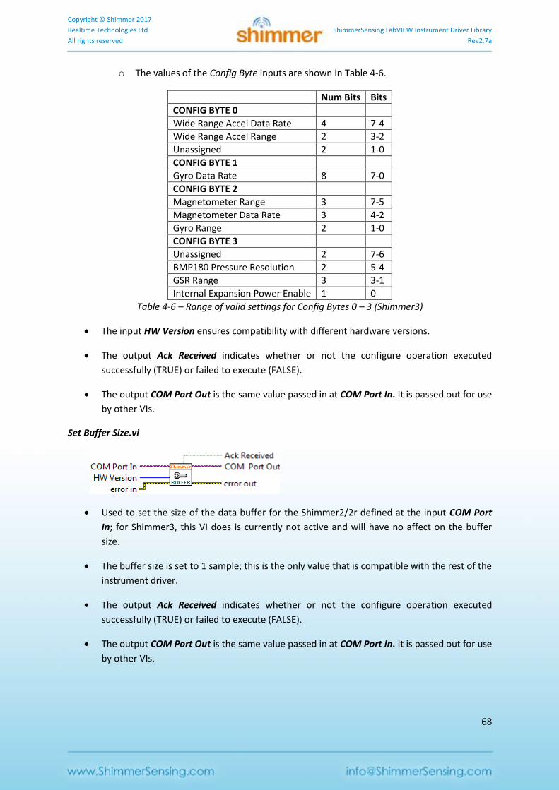
Copyright © Shimmer 2017
Realtime Technologies Ltd ShimmerSensing LabVIEW Instrument Driver Library
All rights reserved Rev2.7a
68
o The values of the Config Byte inputs are shown in Table 4-6.
Num Bits Bits
CONFIG BYTE 0
Wide Range Accel Data Rate 4 7-4
Wide Range Accel Range 2 3-2
Unassigned 2 1-0
CONFIG BYTE 1
Gyro Data Rate 8 7-0
CONFIG BYTE 2
Magnetometer Range 3 7-5
Magnetometer Data Rate 3 4-2
Gyro Range 2 1-0
CONFIG BYTE 3
Unassigned 2 7-6
BMP180 Pressure Resolution 2 5-4
GSR Range 3 3-1
Internal Expansion Power Enable 1 0
Table 4-6 – Range of valid settings for Config Bytes 0 – 3 (Shimmer3)
The input HW Version ensures compatibility with different hardware versions.
The output Ack Received indicates whether or not the configure operation executed
successfully (TRUE) or failed to execute (FALSE).
The output COM Port Out is the same value passed in at COM Port In. It is passed out for use
by other VIs.
Set Buffer Size.vi
Used to set the size of the data buffer for the Shimmer2/2r defined at the input COM Port
In; for Shimmer3, this VI does is currently not active and will have no affect on the buffer
size.
The buffer size is set to 1 sample; this is the only value that is compatible with the rest of the
instrument driver.
The output Ack Received indicates whether or not the configure operation executed
successfully (TRUE) or failed to execute (FALSE).
The output COM Port Out is the same value passed in at COM Port In. It is passed out for use
by other VIs.
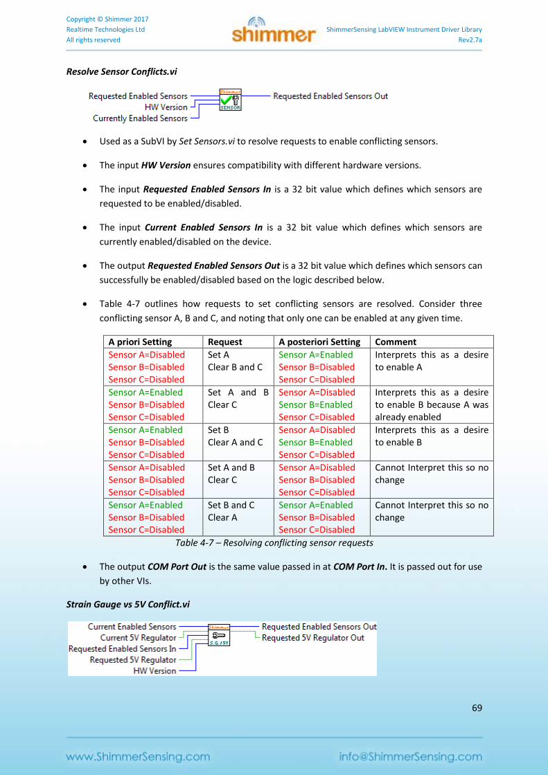
Copyright © Shimmer 2017
Realtime Technologies Ltd ShimmerSensing LabVIEW Instrument Driver Library
All rights reserved Rev2.7a
69
Resolve Sensor Conflicts.vi
Used as a SubVI by Set Sensors.vi to resolve requests to enable conflicting sensors.
The input HW Version ensures compatibility with different hardware versions.
The input Requested Enabled Sensors In is a 32 bit value which defines which sensors are
requested to be enabled/disabled.
The input Current Enabled Sensors In is a 32 bit value which defines which sensors are
currently enabled/disabled on the device.
The output Requested Enabled Sensors Out is a 32 bit value which defines which sensors can
successfully be enabled/disabled based on the logic described below.
Table 4-7 outlines how requests to set conflicting sensors are resolved. Consider three
conflicting sensor A, B and C, and noting that only one can be enabled at any given time.
A priori Setting Request A posteriori Setting Comment
Sensor A=Disabled Sensor B=Disabled Sensor C=Disabled
Set A Clear B and C
Sensor A=Enabled Sensor B=Disabled Sensor C=Disabled
Interprets this as a desire to enable A
Sensor A=Enabled Sensor B=Disabled Sensor C=Disabled
Set A and B Clear C
Sensor A=Disabled Sensor B=Enabled Sensor C=Disabled
Interprets this as a desire to enable B because A was already enabled
Sensor A=Enabled Sensor B=Disabled Sensor C=Disabled
Set B Clear A and C
Sensor A=Disabled Sensor B=Enabled Sensor C=Disabled
Interprets this as a desire to enable B
Sensor A=Disabled Sensor B=Disabled Sensor C=Disabled
Set A and B Clear C
Sensor A=Disabled Sensor B=Disabled Sensor C=Disabled
Cannot Interpret this so no change
Sensor A=Enabled Sensor B=Disabled Sensor C=Disabled
Set B and C Clear A
Sensor A=Enabled Sensor B=Disabled Sensor C=Disabled
Cannot Interpret this so no change
Table 4-7 – Resolving conflicting sensor requests
The output COM Port Out is the same value passed in at COM Port In. It is passed out for use
by other VIs.
Strain Gauge vs 5V Conflict.vi
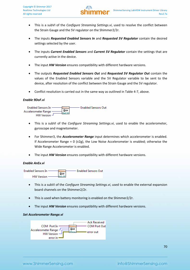
Copyright © Shimmer 2017
Realtime Technologies Ltd ShimmerSensing LabVIEW Instrument Driver Library
All rights reserved Rev2.7a
70
This is a subVI of the Configure Streaming Settings.vi, used to resolve the conflict between
the Strain Gauge and the 5V regulator on the Shimmer2/2r.
The inputs Requested Enabled Sensors In and Requested 5V Regulator contain the desired
settings selected by the user.
The inputs Current Enabled Sensors and Current 5V Regulator contain the settings that are
currently active in the device.
The input HW Version ensures compatibility with different hardware versions.
The outputs Requested Enabled Sensors Out and Requested 5V Regulator Out contain the
values of the Enabled Sensors variable and the 5V Regulator variable to be sent to the
device, after resolution of the conflict between the Strain Gauge and the 5V regulator.
Conflict resolution is carried out in the same way as outlined in Table 4-7, above.
Enable 9DoF.vi
This is a subVI of the Configure Streaming Settings.vi, used to enable the accelerometer,
gyroscope and magnetometer.
For Shimmer3, the Accelerometer Range input determines which accelerometer is enabled.
If Accelerometer Range = 0 (±2g), the Low Noise Accelerometer is enabled; otherwise the
Wide Range Accelerometer is enabled.
The input HW Version ensures compatibility with different hardware versions.
Enable AnEx.vi
This is a subVI of the Configure Streaming Settings.vi, used to enable the external expansion
board channels on the Shimmer2/2r.
This is used when battery monitoring is enabled on the Shimmer2/2r.
The input HW Version ensures compatibility with different hardware versions.
Set Accelerometer Range.vi
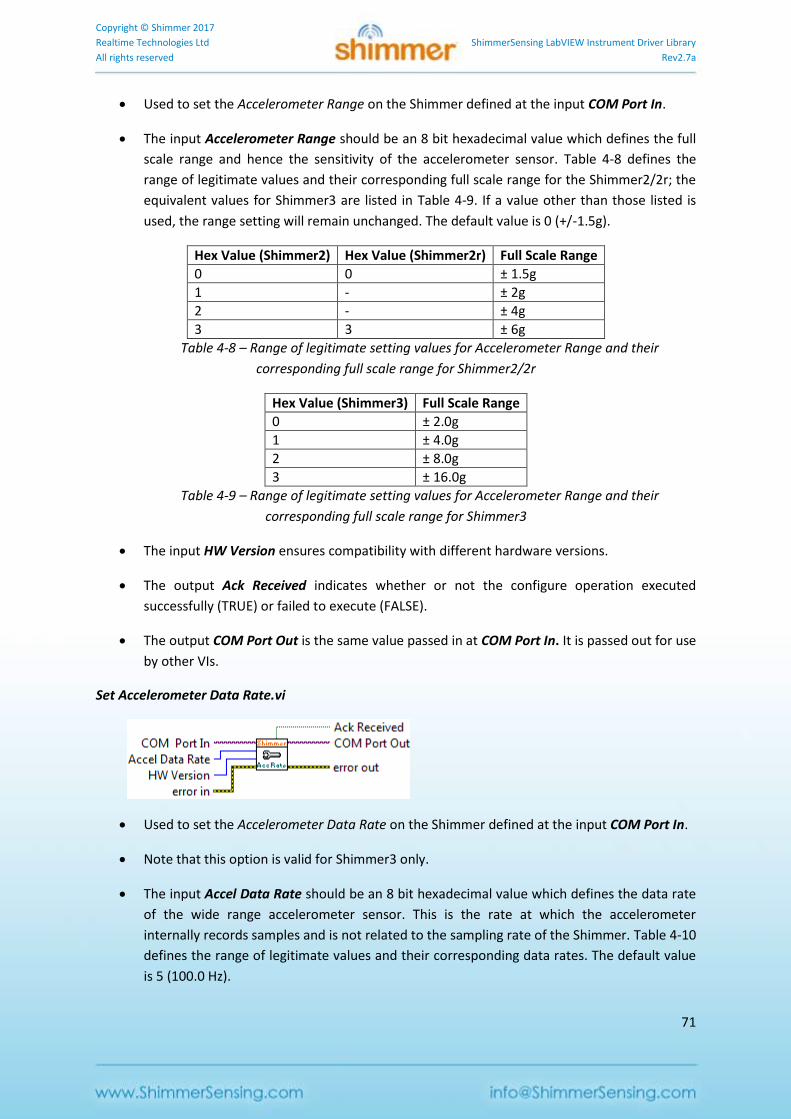
Copyright © Shimmer 2017
Realtime Technologies Ltd ShimmerSensing LabVIEW Instrument Driver Library
All rights reserved Rev2.7a
71
Used to set the Accelerometer Range on the Shimmer defined at the input COM Port In.
The input Accelerometer Range should be an 8 bit hexadecimal value which defines the full
scale range and hence the sensitivity of the accelerometer sensor. Table 4-8 defines the
range of legitimate values and their corresponding full scale range for the Shimmer2/2r; the
equivalent values for Shimmer3 are listed in Table 4-9. If a value other than those listed is
used, the range setting will remain unchanged. The default value is 0 (+/-1.5g).
Hex Value (Shimmer2) Hex Value (Shimmer2r) Full Scale Range
0 0 ± 1.5g
1 - ± 2g
2 - ± 4g
3 3 ± 6g
Table 4-8 – Range of legitimate setting values for Accelerometer Range and their
corresponding full scale range for Shimmer2/2r
Hex Value (Shimmer3) Full Scale Range
0 ± 2.0g
1 ± 4.0g
2 ± 8.0g
3 ± 16.0g
Table 4-9 – Range of legitimate setting values for Accelerometer Range and their
corresponding full scale range for Shimmer3
The input HW Version ensures compatibility with different hardware versions.
The output Ack Received indicates whether or not the configure operation executed
successfully (TRUE) or failed to execute (FALSE).
The output COM Port Out is the same value passed in at COM Port In. It is passed out for use
by other VIs.
Set Accelerometer Data Rate.vi
Used to set the Accelerometer Data Rate on the Shimmer defined at the input COM Port In.
Note that this option is valid for Shimmer3 only.
The input Accel Data Rate should be an 8 bit hexadecimal value which defines the data rate
of the wide range accelerometer sensor. This is the rate at which the accelerometer
internally records samples and is not related to the sampling rate of the Shimmer. Table 4-10
defines the range of legitimate values and their corresponding data rates. The default value
is 5 (100.0 Hz).
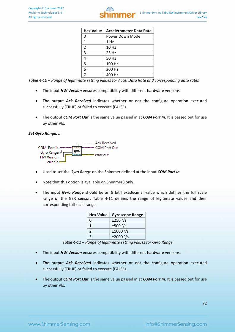
Copyright © Shimmer 2017
Realtime Technologies Ltd ShimmerSensing LabVIEW Instrument Driver Library
All rights reserved Rev2.7a
72
Hex Value Accelerometer Data Rate
0 Power Down Mode
1 1 Hz
2 10 Hz
3 25 Hz
4 50 Hz
5 100 Hz
6 200 Hz
7 400 Hz
Table 4-10 – Range of legitimate setting values for Accel Data Rate and corresponding data rates
The input HW Version ensures compatibility with different hardware versions.
The output Ack Received indicates whether or not the configure operation executed
successfully (TRUE) or failed to execute (FALSE).
The output COM Port Out is the same value passed in at COM Port In. It is passed out for use
by other VIs.
Set Gyro Range.vi
Used to set the Gyro Range on the Shimmer defined at the input COM Port In.
Note that this option is available on Shimmer3 only.
The input Gyro Range should be an 8 bit hexadecimal value which defines the full scale
range of the GSR sensor. Table 4-11 defines the range of legitimate values and their
corresponding full scale range.
Hex Value Gyroscope Range
0 ±250 °/s
1 ±500 °/s
2 ±1000 °/s
3 ±2000 °/s
Table 4-11 – Range of legitimate setting values for Gyro Range
The input HW Version ensures compatibility with different hardware versions.
The output Ack Received indicates whether or not the configure operation executed
successfully (TRUE) or failed to execute (FALSE).
The output COM Port Out is the same value passed in at COM Port In. It is passed out for use
by other VIs.
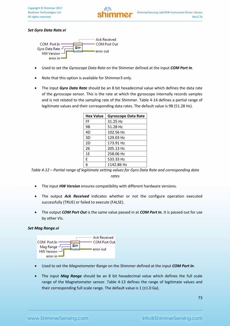
Copyright © Shimmer 2017
Realtime Technologies Ltd ShimmerSensing LabVIEW Instrument Driver Library
All rights reserved Rev2.7a
73
Set Gyro Data Rate.vi
Used to set the Gyroscope Data Rate on the Shimmer defined at the input COM Port In.
Note that this option is available for Shimmer3 only.
The input Gyro Data Rate should be an 8 bit hexadecimal value which defines the data rate
of the gyroscope sensor. This is the rate at which the gyroscope internally records samples
and is not related to the sampling rate of the Shimmer. Table 4-14 defines a partial range of
legitimate values and their corresponding data rates. The default value is 9B (51.28 Hz).
Hex Value Gyroscope Data Rate
FF 31.25 Hz
9B 51.28 Hz
4D 102.56 Hz
3D 129.03 Hz
2D 173.91 Hz
26 205.13 Hz
1E 258.06 Hz
E 533.33 Hz
6 1142.86 Hz
Table 4-12 – Partial range of legitimate setting values for Gyro Data Rate and corresponding data
rates
The input HW Version ensures compatibility with different hardware versions.
The output Ack Received indicates whether or not the configure operation executed
successfully (TRUE) or failed to execute (FALSE).
The output COM Port Out is the same value passed in at COM Port In. It is passed out for use
by other VIs.
Set Mag Range.vi
Used to set the Magnetometer Range on the Shimmer defined at the input COM Port In.
The input Mag Range should be an 8 bit hexadecimal value which defines the full scale
range of the Magnetometer sensor. Table 4-13 defines the range of legitimate values and
their corresponding full scale range. The default value is 1 (±1.0 Ga).
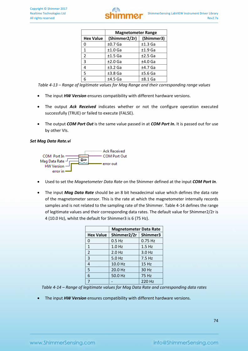
Copyright © Shimmer 2017
Realtime Technologies Ltd ShimmerSensing LabVIEW Instrument Driver Library
All rights reserved Rev2.7a
74
Magnetometer Range
Hex Value (Shimmer2/2r) (Shimmer3)
0 ±0.7 Ga ±1.3 Ga
1 ±1.0 Ga ±1.9 Ga
2 ±1.5 Ga ±2.5 Ga
3 ±2.0 Ga ±4.0 Ga
4 ±3.2 Ga ±4.7 Ga
5 ±3.8 Ga ±5.6 Ga
6 ±4.5 Ga ±8.1 Ga
Table 4-13 – Range of legitimate values for Mag Range and their corresponding range values
The input HW Version ensures compatibility with different hardware versions.
The output Ack Received indicates whether or not the configure operation executed
successfully (TRUE) or failed to execute (FALSE).
The output COM Port Out is the same value passed in at COM Port In. It is passed out for use
by other VIs.
Set Mag Data Rate.vi
Used to set the Magnetometer Data Rate on the Shimmer defined at the input COM Port In.
The input Mag Data Rate should be an 8 bit hexadecimal value which defines the data rate
of the magnetometer sensor. This is the rate at which the magnetometer internally records
samples and is not related to the sampling rate of the Shimmer. Table 4-14 defines the range
of legitimate values and their corresponding data rates. The default value for Shimmer2/2r is
4 (10.0 Hz), whilst the default for Shimmer3 is 6 (75 Hz).
Magnetometer Data Rate
Hex Value Shimmer2/2r Shimmer3
0 0.5 Hz 0.75 Hz
1 1.0 Hz 1.5 Hz
2 2.0 Hz 3.0 Hz
3 5.0 Hz 7.5 Hz
4 10.0 Hz 15 Hz
5 20.0 Hz 30 Hz
6 50.0 Hz 75 Hz
7 - 220 Hz
Table 4-14 – Range of legitimate values for Mag Data Rate and corresponding data rates
The input HW Version ensures compatibility with different hardware versions.
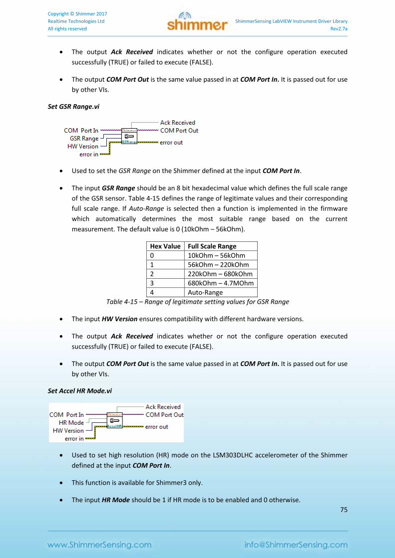
Copyright © Shimmer 2017
Realtime Technologies Ltd ShimmerSensing LabVIEW Instrument Driver Library
All rights reserved Rev2.7a
75
The output Ack Received indicates whether or not the configure operation executed
successfully (TRUE) or failed to execute (FALSE).
The output COM Port Out is the same value passed in at COM Port In. It is passed out for use
by other VIs.
Set GSR Range.vi
Used to set the GSR Range on the Shimmer defined at the input COM Port In.
The input GSR Range should be an 8 bit hexadecimal value which defines the full scale range
of the GSR sensor. Table 4-15 defines the range of legitimate values and their corresponding
full scale range. If Auto-Range is selected then a function is implemented in the firmware
which automatically determines the most suitable range based on the current
measurement. The default value is 0 (10kOhm – 56kOhm).
Hex Value Full Scale Range
0 10kOhm – 56kOhm
1 56kOhm – 220kOhm
2 220kOhm – 680kOhm
3 680kOhm – 4.7MOhm
4 Auto-Range
Table 4-15 – Range of legitimate setting values for GSR Range
The input HW Version ensures compatibility with different hardware versions.
The output Ack Received indicates whether or not the configure operation executed
successfully (TRUE) or failed to execute (FALSE).
The output COM Port Out is the same value passed in at COM Port In. It is passed out for use
by other VIs.
Set Accel HR Mode.vi
Used to set high resolution (HR) mode on the LSM303DLHC accelerometer of the Shimmer
defined at the input COM Port In.
This function is available for Shimmer3 only.
The input HR Mode should be 1 if HR mode is to be enabled and 0 otherwise.
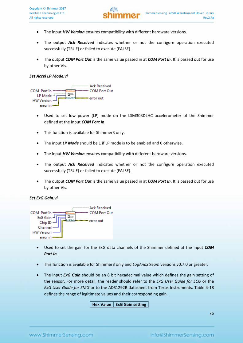
Copyright © Shimmer 2017
Realtime Technologies Ltd ShimmerSensing LabVIEW Instrument Driver Library
All rights reserved Rev2.7a
76
The input HW Version ensures compatibility with different hardware versions.
The output Ack Received indicates whether or not the configure operation executed
successfully (TRUE) or failed to execute (FALSE).
The output COM Port Out is the same value passed in at COM Port In. It is passed out for use
by other VIs.
Set Accel LP Mode.vi
Used to set low power (LP) mode on the LSM303DLHC accelerometer of the Shimmer
defined at the input COM Port In.
This function is available for Shimmer3 only.
The input LP Mode should be 1 if LP mode is to be enabled and 0 otherwise.
The input HW Version ensures compatibility with different hardware versions.
The output Ack Received indicates whether or not the configure operation executed
successfully (TRUE) or failed to execute (FALSE).
The output COM Port Out is the same value passed in at COM Port In. It is passed out for use
by other VIs.
Set ExG Gain.vi
Used to set the gain for the ExG data channels of the Shimmer defined at the input COM
Port In.
This function is available for Shimmer3 only and LogAndStream versions v0.7.0 or greater.
The input ExG Gain should be an 8 bit hexadecimal value which defines the gain setting of
the sensor. For more detail, the reader should refer to the ExG User Guide for ECG or the
ExG User Guide for EMG or to the ADS1292R datasheet from Texas Instruments. Table 4-18
defines the range of legitimate values and their corresponding gain.
Hex Value ExG Gain setting
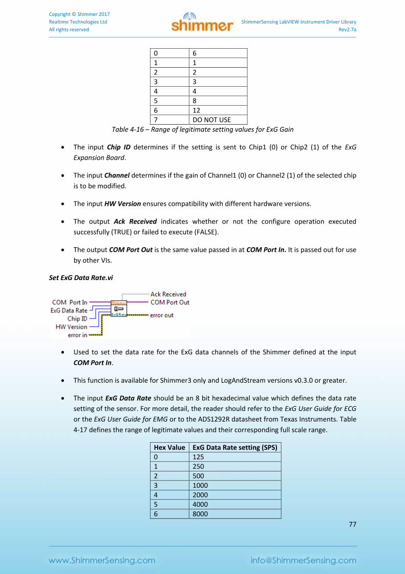
Copyright © Shimmer 2017
Realtime Technologies Ltd ShimmerSensing LabVIEW Instrument Driver Library
All rights reserved Rev2.7a
77
0 6
1 1
2 2
3 3
4 4
5 8
6 12
7 DO NOT USE
Table 4-16 – Range of legitimate setting values for ExG Gain
The input Chip ID determines if the setting is sent to Chip1 (0) or Chip2 (1) of the ExG
Expansion Board.
The input Channel determines if the gain of Channel1 (0) or Channel2 (1) of the selected chip
is to be modified.
The input HW Version ensures compatibility with different hardware versions.
The output Ack Received indicates whether or not the configure operation executed
successfully (TRUE) or failed to execute (FALSE).
The output COM Port Out is the same value passed in at COM Port In. It is passed out for use
by other VIs.
Set ExG Data Rate.vi
Used to set the data rate for the ExG data channels of the Shimmer defined at the input
COM Port In.
This function is available for Shimmer3 only and LogAndStream versions v0.3.0 or greater.
The input ExG Data Rate should be an 8 bit hexadecimal value which defines the data rate
setting of the sensor. For more detail, the reader should refer to the ExG User Guide for ECG
or the ExG User Guide for EMG or to the ADS1292R datasheet from Texas Instruments. Table
4-17 defines the range of legitimate values and their corresponding full scale range.
Hex Value ExG Data Rate setting (SPS)
0 125
1 250
2 500
3 1000
4 2000
5 4000
6 8000
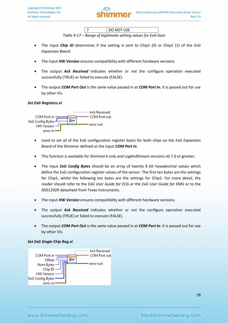
Copyright © Shimmer 2017
Realtime Technologies Ltd ShimmerSensing LabVIEW Instrument Driver Library
All rights reserved Rev2.7a
78
7 DO NOT USE
Table 4-17 – Range of legitimate setting values for ExG Gain
The input Chip ID determines if the setting is sent to Chip1 (0) or Chip2 (1) of the ExG
Expansion Board.
The input HW Version ensures compatibility with different hardware versions.
The output Ack Received indicates whether or not the configure operation executed
successfully (TRUE) or failed to execute (FALSE).
The output COM Port Out is the same value passed in at COM Port In. It is passed out for use
by other VIs.
Set ExG Registers.vi
Used to set all of the ExG configuration register bytes for both chips on the ExG Expansion
Board of the Shimmer defined at the input COM Port In.
This function is available for Shimmer3 only and LogAndStream versions v0.7.0 or greater.
The input ExG Config Bytes should be an array of twenty 8 bit hexadecimal values which
define the ExG configuration register values of the sensor. The first ten bytes are the settings
for Chip1, whilst the following ten bytes are the settings for Chip2. For more detail, the
reader should refer to the ExG User Guide for ECG or the ExG User Guide for EMG or to the
ADS1292R datasheet from Texas Instruments.
The input HW Version ensures compatibility with different hardware versions.
The output Ack Received indicates whether or not the configure operation executed
successfully (TRUE) or failed to execute (FALSE).
The output COM Port Out is the same value passed in at COM Port In. It is passed out for use
by other VIs.
Set ExG Single Chip Reg.vi
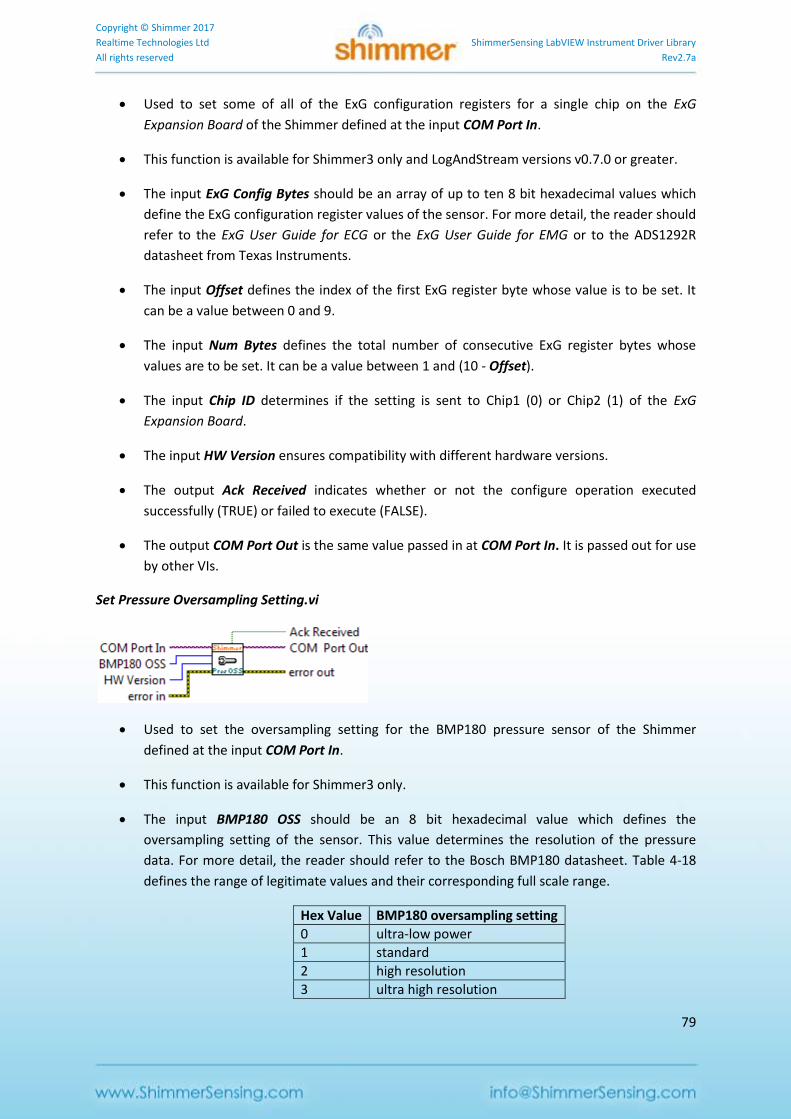
Copyright © Shimmer 2017
Realtime Technologies Ltd ShimmerSensing LabVIEW Instrument Driver Library
All rights reserved Rev2.7a
79
Used to set some of all of the ExG configuration registers for a single chip on the ExG
Expansion Board of the Shimmer defined at the input COM Port In.
This function is available for Shimmer3 only and LogAndStream versions v0.7.0 or greater.
The input ExG Config Bytes should be an array of up to ten 8 bit hexadecimal values which
define the ExG configuration register values of the sensor. For more detail, the reader should
refer to the ExG User Guide for ECG or the ExG User Guide for EMG or to the ADS1292R
datasheet from Texas Instruments.
The input Offset defines the index of the first ExG register byte whose value is to be set. It
can be a value between 0 and 9.
The input Num Bytes defines the total number of consecutive ExG register bytes whose
values are to be set. It can be a value between 1 and (10 - Offset).
The input Chip ID determines if the setting is sent to Chip1 (0) or Chip2 (1) of the ExG
Expansion Board.
The input HW Version ensures compatibility with different hardware versions.
The output Ack Received indicates whether or not the configure operation executed
successfully (TRUE) or failed to execute (FALSE).
The output COM Port Out is the same value passed in at COM Port In. It is passed out for use
by other VIs.
Set Pressure Oversampling Setting.vi
Used to set the oversampling setting for the BMP180 pressure sensor of the Shimmer
defined at the input COM Port In.
This function is available for Shimmer3 only.
The input BMP180 OSS should be an 8 bit hexadecimal value which defines the
oversampling setting of the sensor. This value determines the resolution of the pressure
data. For more detail, the reader should refer to the Bosch BMP180 datasheet. Table 4-18
defines the range of legitimate values and their corresponding full scale range.
Hex Value BMP180 oversampling setting
0 ultra-low power
1 standard
2 high resolution
3 ultra high resolution
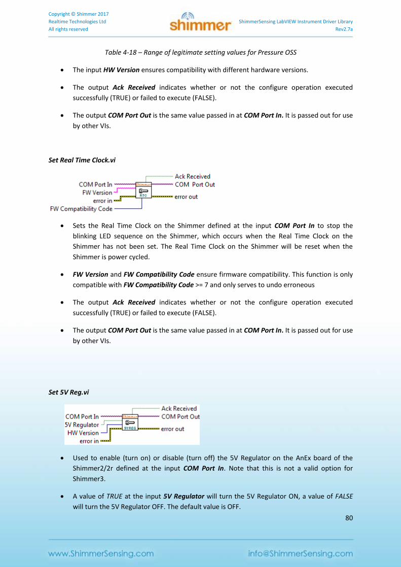
Copyright © Shimmer 2017
Realtime Technologies Ltd ShimmerSensing LabVIEW Instrument Driver Library
All rights reserved Rev2.7a
80
Table 4-18 – Range of legitimate setting values for Pressure OSS
The input HW Version ensures compatibility with different hardware versions.
The output Ack Received indicates whether or not the configure operation executed
successfully (TRUE) or failed to execute (FALSE).
The output COM Port Out is the same value passed in at COM Port In. It is passed out for use
by other VIs.
Set Real Time Clock.vi
Sets the Real Time Clock on the Shimmer defined at the input COM Port In to stop the
blinking LED sequence on the Shimmer, which occurs when the Real Time Clock on the
Shimmer has not been set. The Real Time Clock on the Shimmer will be reset when the
Shimmer is power cycled.
FW Version and FW Compatibility Code ensure firmware compatibility. This function is only
compatible with FW Compatibility Code >= 7 and only serves to undo erroneous
The output Ack Received indicates whether or not the configure operation executed
successfully (TRUE) or failed to execute (FALSE).
The output COM Port Out is the same value passed in at COM Port In. It is passed out for use
by other VIs.
Set 5V Reg.vi
Used to enable (turn on) or disable (turn off) the 5V Regulator on the AnEx board of the
Shimmer2/2r defined at the input COM Port In. Note that this is not a valid option for
Shimmer3.
A value of TRUE at the input 5V Regulator will turn the 5V Regulator ON, a value of FALSE
will turn the 5V Regulator OFF. The default value is OFF.
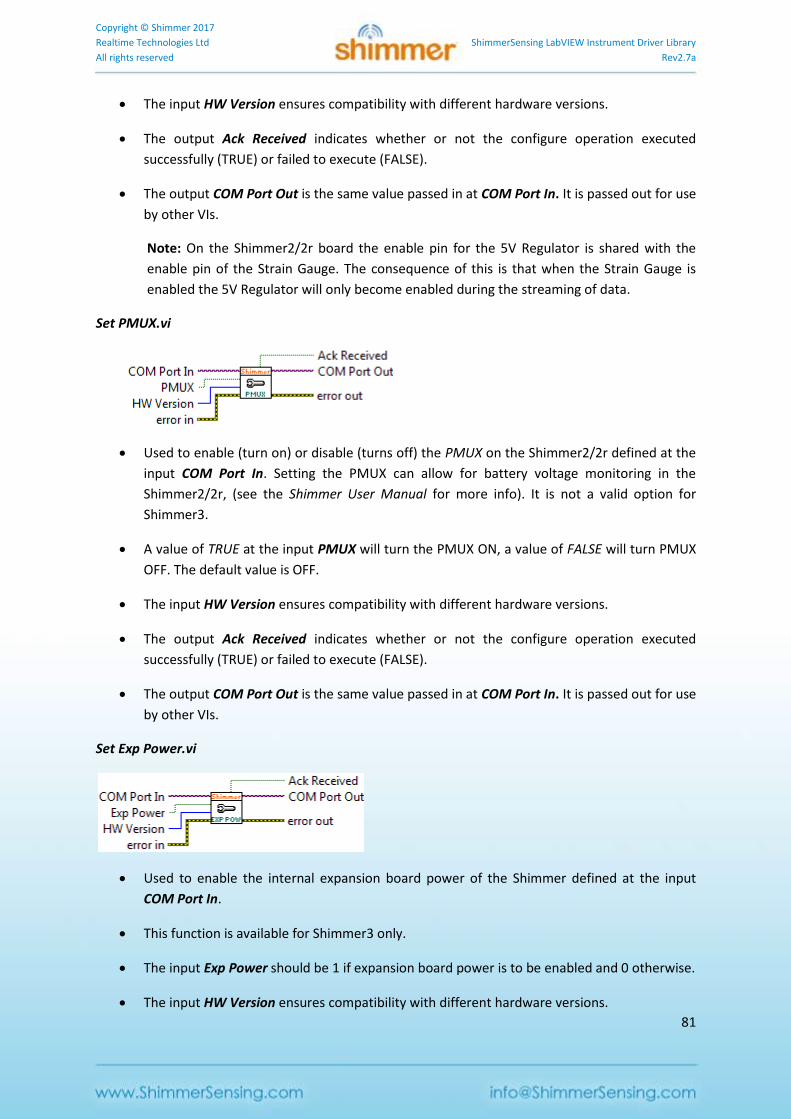
Copyright © Shimmer 2017
Realtime Technologies Ltd ShimmerSensing LabVIEW Instrument Driver Library
All rights reserved Rev2.7a
81
The input HW Version ensures compatibility with different hardware versions.
The output Ack Received indicates whether or not the configure operation executed
successfully (TRUE) or failed to execute (FALSE).
The output COM Port Out is the same value passed in at COM Port In. It is passed out for use
by other VIs.
Note: On the Shimmer2/2r board the enable pin for the 5V Regulator is shared with the
enable pin of the Strain Gauge. The consequence of this is that when the Strain Gauge is
enabled the 5V Regulator will only become enabled during the streaming of data.
Set PMUX.vi
Used to enable (turn on) or disable (turns off) the PMUX on the Shimmer2/2r defined at the
input COM Port In. Setting the PMUX can allow for battery voltage monitoring in the
Shimmer2/2r, (see the Shimmer User Manual for more info). It is not a valid option for
Shimmer3.
A value of TRUE at the input PMUX will turn the PMUX ON, a value of FALSE will turn PMUX
OFF. The default value is OFF.
The input HW Version ensures compatibility with different hardware versions.
The output Ack Received indicates whether or not the configure operation executed
successfully (TRUE) or failed to execute (FALSE).
The output COM Port Out is the same value passed in at COM Port In. It is passed out for use
by other VIs.
Set Exp Power.vi
Used to enable the internal expansion board power of the Shimmer defined at the input
COM Port In.
This function is available for Shimmer3 only.
The input Exp Power should be 1 if expansion board power is to be enabled and 0 otherwise.
The input HW Version ensures compatibility with different hardware versions.
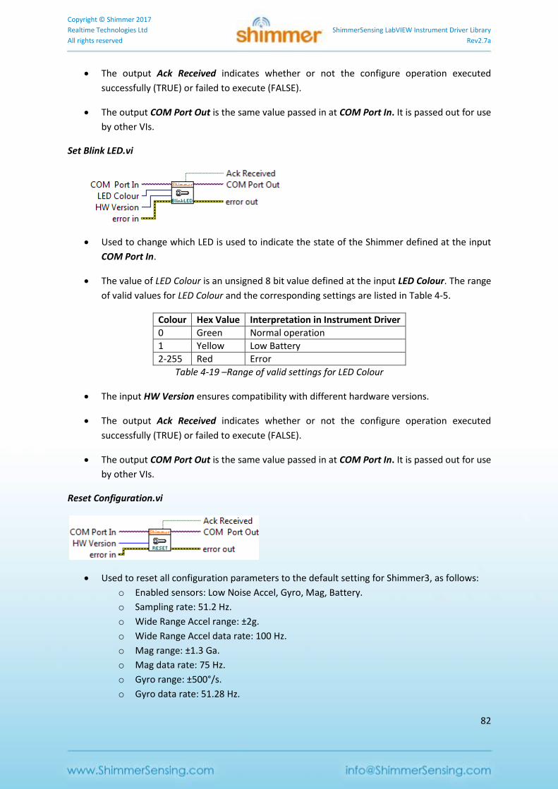
Copyright © Shimmer 2017
Realtime Technologies Ltd ShimmerSensing LabVIEW Instrument Driver Library
All rights reserved Rev2.7a
82
The output Ack Received indicates whether or not the configure operation executed
successfully (TRUE) or failed to execute (FALSE).
The output COM Port Out is the same value passed in at COM Port In. It is passed out for use
by other VIs.
Set Blink LED.vi
Used to change which LED is used to indicate the state of the Shimmer defined at the input
COM Port In.
The value of LED Colour is an unsigned 8 bit value defined at the input LED Colour. The range
of valid values for LED Colour and the corresponding settings are listed in Table 4-5.
Colour Hex Value Interpretation in Instrument Driver
0 Green Normal operation
1 Yellow Low Battery
2-255 Red Error
Table 4-19 –Range of valid settings for LED Colour
The input HW Version ensures compatibility with different hardware versions.
The output Ack Received indicates whether or not the configure operation executed
successfully (TRUE) or failed to execute (FALSE).
The output COM Port Out is the same value passed in at COM Port In. It is passed out for use
by other VIs.
Reset Configuration.vi
Used to reset all configuration parameters to the default setting for Shimmer3, as follows:
o Enabled sensors: Low Noise Accel, Gyro, Mag, Battery.
o Sampling rate: 51.2 Hz.
o Wide Range Accel range: ±2g.
o Wide Range Accel data rate: 100 Hz.
o Mag range: ±1.3 Ga.
o Mag data rate: 75 Hz.
o Gyro range: ±500°/s.
o Gyro data rate: 51.28 Hz.
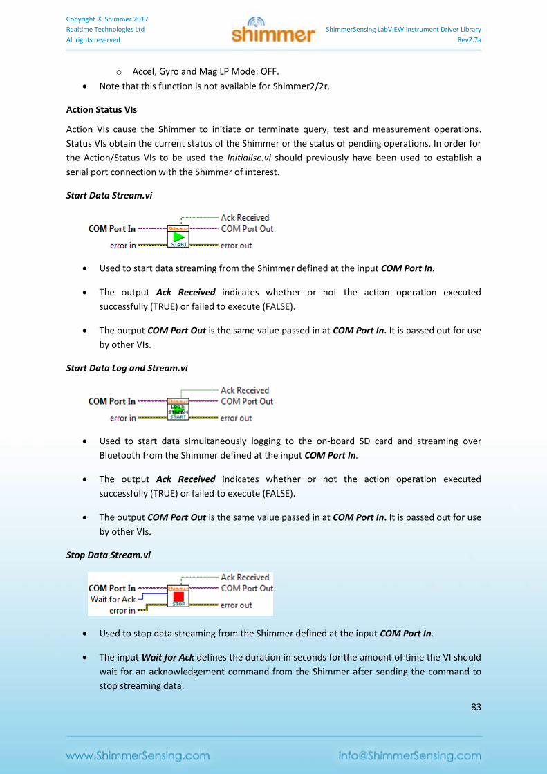
Copyright © Shimmer 2017
Realtime Technologies Ltd ShimmerSensing LabVIEW Instrument Driver Library
All rights reserved Rev2.7a
83
o Accel, Gyro and Mag LP Mode: OFF.
Note that this function is not available for Shimmer2/2r.
Action Status VIs
Action VIs cause the Shimmer to initiate or terminate query, test and measurement operations.
Status VIs obtain the current status of the Shimmer or the status of pending operations. In order for
the Action/Status VIs to be used the Initialise.vi should previously have been used to establish a
serial port connection with the Shimmer of interest.
Start Data Stream.vi
Used to start data streaming from the Shimmer defined at the input COM Port In.
The output Ack Received indicates whether or not the action operation executed
successfully (TRUE) or failed to execute (FALSE).
The output COM Port Out is the same value passed in at COM Port In. It is passed out for use
by other VIs.
Start Data Log and Stream.vi
Used to start data simultaneously logging to the on-board SD card and streaming over
Bluetooth from the Shimmer defined at the input COM Port In.
The output Ack Received indicates whether or not the action operation executed
successfully (TRUE) or failed to execute (FALSE).
The output COM Port Out is the same value passed in at COM Port In. It is passed out for use
by other VIs.
Stop Data Stream.vi
Used to stop data streaming from the Shimmer defined at the input COM Port In.
The input Wait for Ack defines the duration in seconds for the amount of time the VI should
wait for an acknowledgement command from the Shimmer after sending the command to
stop streaming data.
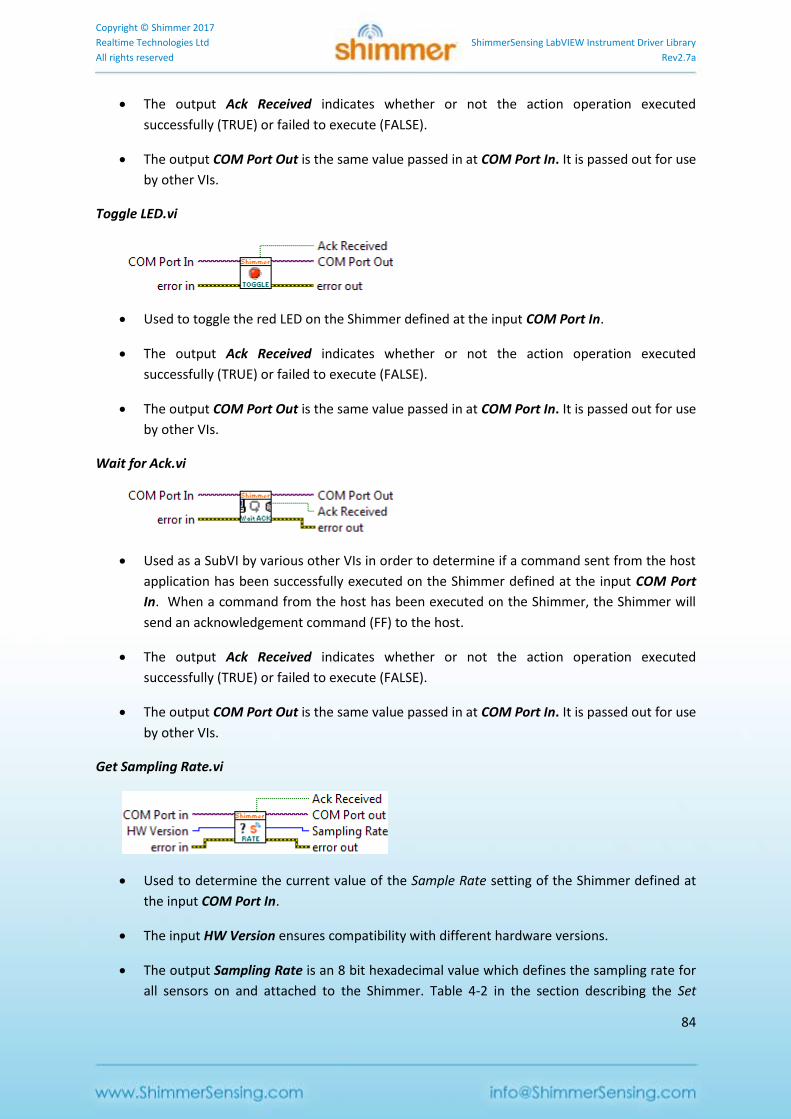
Copyright © Shimmer 2017
Realtime Technologies Ltd ShimmerSensing LabVIEW Instrument Driver Library
All rights reserved Rev2.7a
84
The output Ack Received indicates whether or not the action operation executed
successfully (TRUE) or failed to execute (FALSE).
The output COM Port Out is the same value passed in at COM Port In. It is passed out for use
by other VIs.
Toggle LED.vi
Used to toggle the red LED on the Shimmer defined at the input COM Port In.
The output Ack Received indicates whether or not the action operation executed
successfully (TRUE) or failed to execute (FALSE).
The output COM Port Out is the same value passed in at COM Port In. It is passed out for use
by other VIs.
Wait for Ack.vi
Used as a SubVI by various other VIs in order to determine if a command sent from the host
application has been successfully executed on the Shimmer defined at the input COM Port
In. When a command from the host has been executed on the Shimmer, the Shimmer will
send an acknowledgement command (FF) to the host.
The output Ack Received indicates whether or not the action operation executed
successfully (TRUE) or failed to execute (FALSE).
The output COM Port Out is the same value passed in at COM Port In. It is passed out for use
by other VIs.
Get Sampling Rate.vi
Used to determine the current value of the Sample Rate setting of the Shimmer defined at
the input COM Port In.
The input HW Version ensures compatibility with different hardware versions.
The output Sampling Rate is an 8 bit hexadecimal value which defines the sampling rate for
all sensors on and attached to the Shimmer. Table 4-2 in the section describing the Set
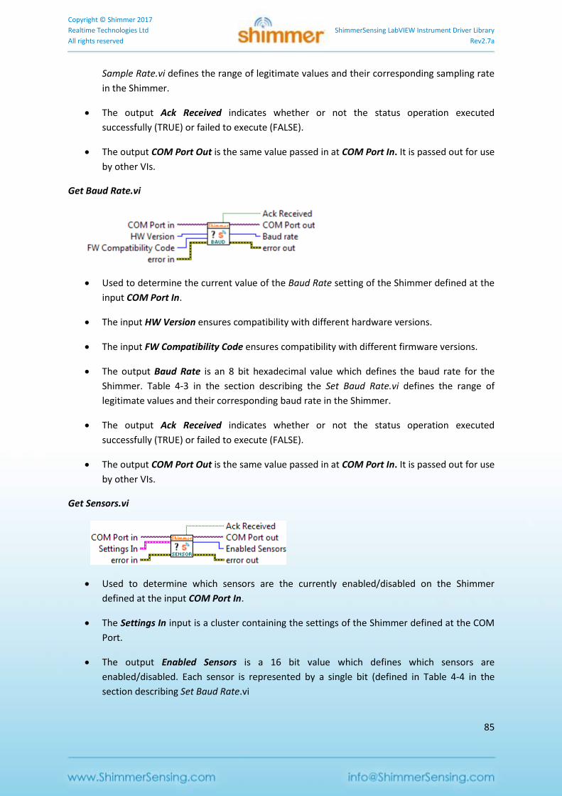
Copyright © Shimmer 2017
Realtime Technologies Ltd ShimmerSensing LabVIEW Instrument Driver Library
All rights reserved Rev2.7a
85
Sample Rate.vi defines the range of legitimate values and their corresponding sampling rate
in the Shimmer.
The output Ack Received indicates whether or not the status operation executed
successfully (TRUE) or failed to execute (FALSE).
The output COM Port Out is the same value passed in at COM Port In. It is passed out for use
by other VIs.
Get Baud Rate.vi
Used to determine the current value of the Baud Rate setting of the Shimmer defined at the
input COM Port In.
The input HW Version ensures compatibility with different hardware versions.
The input FW Compatibility Code ensures compatibility with different firmware versions.
The output Baud Rate is an 8 bit hexadecimal value which defines the baud rate for the
Shimmer. Table 4-3 in the section describing the Set Baud Rate.vi defines the range of
legitimate values and their corresponding baud rate in the Shimmer.
The output Ack Received indicates whether or not the status operation executed
successfully (TRUE) or failed to execute (FALSE).
The output COM Port Out is the same value passed in at COM Port In. It is passed out for use
by other VIs.
Get Sensors.vi
Used to determine which sensors are the currently enabled/disabled on the Shimmer
defined at the input COM Port In.
The Settings In input is a cluster containing the settings of the Shimmer defined at the COM
Port.
The output Enabled Sensors is a 16 bit value which defines which sensors are
enabled/disabled. Each sensor is represented by a single bit (defined in Table 4-4 in the
section describing Set Baud Rate.vi
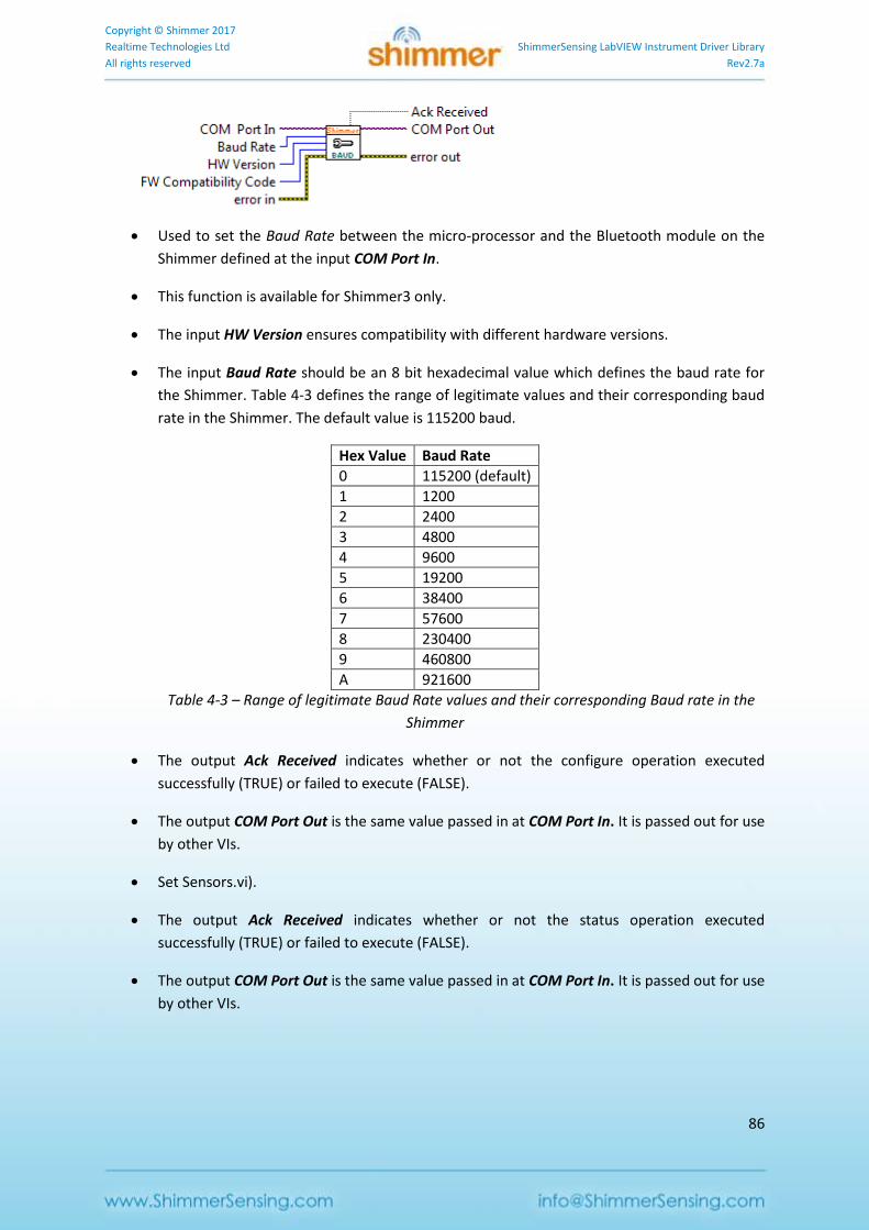
Copyright © Shimmer 2017
Realtime Technologies Ltd ShimmerSensing LabVIEW Instrument Driver Library
All rights reserved Rev2.7a
86
Used to set the Baud Rate between the micro-processor and the Bluetooth module on the
Shimmer defined at the input COM Port In.
This function is available for Shimmer3 only.
The input HW Version ensures compatibility with different hardware versions.
The input Baud Rate should be an 8 bit hexadecimal value which defines the baud rate for
the Shimmer. Table 4-3 defines the range of legitimate values and their corresponding baud
rate in the Shimmer. The default value is 115200 baud.
Hex Value Baud Rate
0 115200 (default)
1 1200
2 2400
3 4800
4 9600
5 19200
6 38400
7 57600
8 230400
9 460800
A 921600
Table 4-3 – Range of legitimate Baud Rate values and their corresponding Baud rate in the
Shimmer
The output Ack Received indicates whether or not the configure operation executed
successfully (TRUE) or failed to execute (FALSE).
The output COM Port Out is the same value passed in at COM Port In. It is passed out for use
by other VIs.
Set Sensors.vi).
The output Ack Received indicates whether or not the status operation executed
successfully (TRUE) or failed to execute (FALSE).
The output COM Port Out is the same value passed in at COM Port In. It is passed out for use
by other VIs.
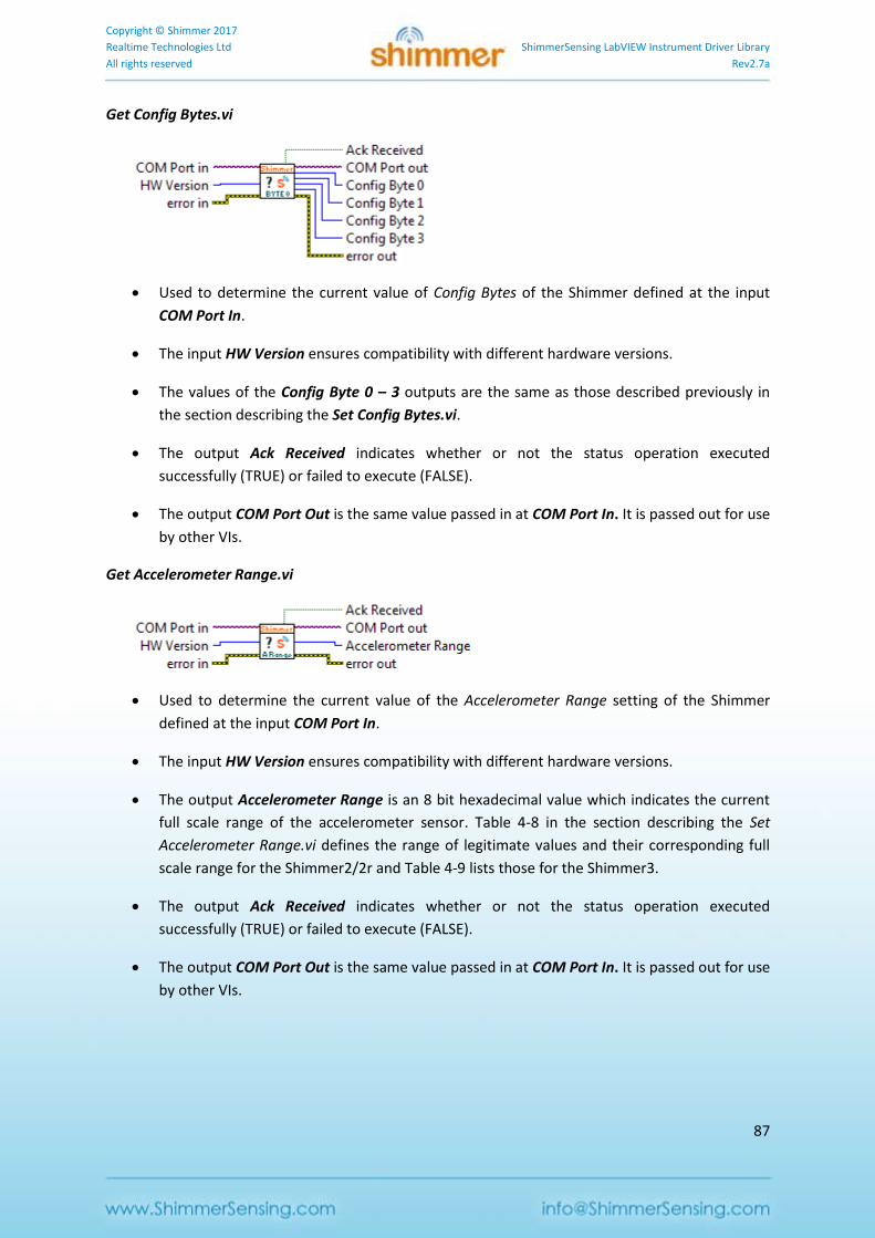
Copyright © Shimmer 2017
Realtime Technologies Ltd ShimmerSensing LabVIEW Instrument Driver Library
All rights reserved Rev2.7a
87
Get Config Bytes.vi
Used to determine the current value of Config Bytes of the Shimmer defined at the input
COM Port In.
The input HW Version ensures compatibility with different hardware versions.
The values of the Config Byte 0 – 3 outputs are the same as those described previously in
the section describing the Set Config Bytes.vi.
The output Ack Received indicates whether or not the status operation executed
successfully (TRUE) or failed to execute (FALSE).
The output COM Port Out is the same value passed in at COM Port In. It is passed out for use
by other VIs.
Get Accelerometer Range.vi
Used to determine the current value of the Accelerometer Range setting of the Shimmer
defined at the input COM Port In.
The input HW Version ensures compatibility with different hardware versions.
The output Accelerometer Range is an 8 bit hexadecimal value which indicates the current
full scale range of the accelerometer sensor. Table 4-8 in the section describing the Set
Accelerometer Range.vi defines the range of legitimate values and their corresponding full
scale range for the Shimmer2/2r and Table 4-9 lists those for the Shimmer3.
The output Ack Received indicates whether or not the status operation executed
successfully (TRUE) or failed to execute (FALSE).
The output COM Port Out is the same value passed in at COM Port In. It is passed out for use
by other VIs.
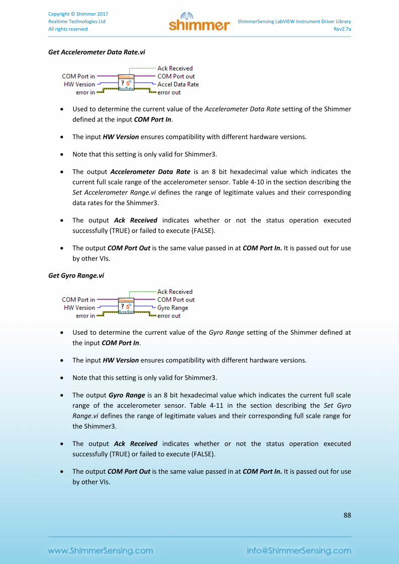
Copyright © Shimmer 2017
Realtime Technologies Ltd ShimmerSensing LabVIEW Instrument Driver Library
All rights reserved Rev2.7a
88
Get Accelerometer Data Rate.vi
Used to determine the current value of the Accelerometer Data Rate setting of the Shimmer
defined at the input COM Port In.
The input HW Version ensures compatibility with different hardware versions.
Note that this setting is only valid for Shimmer3.
The output Accelerometer Data Rate is an 8 bit hexadecimal value which indicates the
current full scale range of the accelerometer sensor. Table 4-10 in the section describing the
Set Accelerometer Range.vi defines the range of legitimate values and their corresponding
data rates for the Shimmer3.
The output Ack Received indicates whether or not the status operation executed
successfully (TRUE) or failed to execute (FALSE).
The output COM Port Out is the same value passed in at COM Port In. It is passed out for use
by other VIs.
Get Gyro Range.vi
Used to determine the current value of the Gyro Range setting of the Shimmer defined at
the input COM Port In.
The input HW Version ensures compatibility with different hardware versions.
Note that this setting is only valid for Shimmer3.
The output Gyro Range is an 8 bit hexadecimal value which indicates the current full scale
range of the accelerometer sensor. Table 4-11 in the section describing the Set Gyro
Range.vi defines the range of legitimate values and their corresponding full scale range for
the Shimmer3.
The output Ack Received indicates whether or not the status operation executed
successfully (TRUE) or failed to execute (FALSE).
The output COM Port Out is the same value passed in at COM Port In. It is passed out for use
by other VIs.
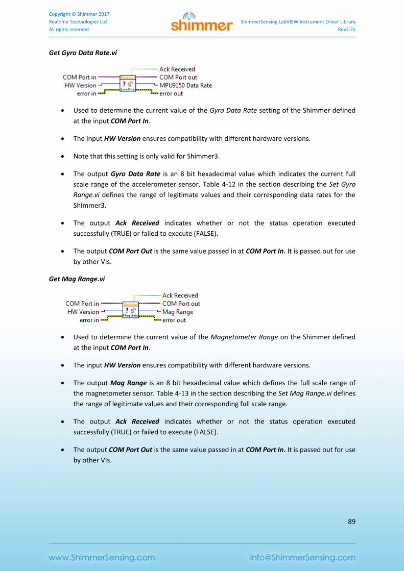
Copyright © Shimmer 2017
Realtime Technologies Ltd ShimmerSensing LabVIEW Instrument Driver Library
All rights reserved Rev2.7a
89
Get Gyro Data Rate.vi
Used to determine the current value of the Gyro Data Rate setting of the Shimmer defined
at the input COM Port In.
The input HW Version ensures compatibility with different hardware versions.
Note that this setting is only valid for Shimmer3.
The output Gyro Data Rate is an 8 bit hexadecimal value which indicates the current full
scale range of the accelerometer sensor. Table 4-12 in the section describing the Set Gyro
Range.vi defines the range of legitimate values and their corresponding data rates for the
Shimmer3.
The output Ack Received indicates whether or not the status operation executed
successfully (TRUE) or failed to execute (FALSE).
The output COM Port Out is the same value passed in at COM Port In. It is passed out for use
by other VIs.
Get Mag Range.vi
Used to determine the current value of the Magnetometer Range on the Shimmer defined
at the input COM Port In.
The input HW Version ensures compatibility with different hardware versions.
The output Mag Range is an 8 bit hexadecimal value which defines the full scale range of
the magnetometer sensor. Table 4-13 in the section describing the Set Mag Range.vi defines
the range of legitimate values and their corresponding full scale range.
The output Ack Received indicates whether or not the status operation executed
successfully (TRUE) or failed to execute (FALSE).
The output COM Port Out is the same value passed in at COM Port In. It is passed out for use
by other VIs.
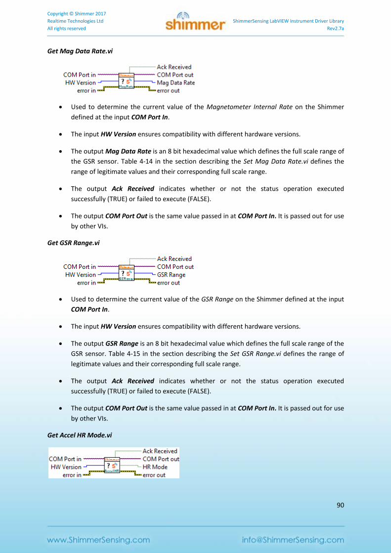
Copyright © Shimmer 2017
Realtime Technologies Ltd ShimmerSensing LabVIEW Instrument Driver Library
All rights reserved Rev2.7a
90
Get Mag Data Rate.vi
Used to determine the current value of the Magnetometer Internal Rate on the Shimmer
defined at the input COM Port In.
The input HW Version ensures compatibility with different hardware versions.
The output Mag Data Rate is an 8 bit hexadecimal value which defines the full scale range of
the GSR sensor. Table 4-14 in the section describing the Set Mag Data Rate.vi defines the
range of legitimate values and their corresponding full scale range.
The output Ack Received indicates whether or not the status operation executed
successfully (TRUE) or failed to execute (FALSE).
The output COM Port Out is the same value passed in at COM Port In. It is passed out for use
by other VIs.
Get GSR Range.vi
Used to determine the current value of the GSR Range on the Shimmer defined at the input
COM Port In.
The input HW Version ensures compatibility with different hardware versions.
The output GSR Range is an 8 bit hexadecimal value which defines the full scale range of the
GSR sensor. Table 4-15 in the section describing the Set GSR Range.vi defines the range of
legitimate values and their corresponding full scale range.
The output Ack Received indicates whether or not the status operation executed
successfully (TRUE) or failed to execute (FALSE).
The output COM Port Out is the same value passed in at COM Port In. It is passed out for use
by other VIs.
Get Accel HR Mode.vi
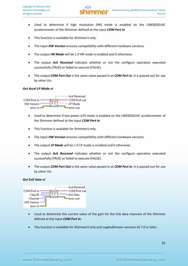
Copyright © Shimmer 2017
Realtime Technologies Ltd ShimmerSensing LabVIEW Instrument Driver Library
All rights reserved Rev2.7a
91
Used to determine if high resolution (HR) mode is enabled on the LSM303DLHC
accelerometer of the Shimmer defined at the input COM Port In.
This function is available for Shimmer3 only.
The input HW Version ensures compatibility with different hardware versions.
The output HR Mode will be 1 if HR mode is enabled and 0 otherwise.
The output Ack Received indicates whether or not the configure operation executed
successfully (TRUE) or failed to execute (FALSE).
The output COM Port Out is the same value passed in at COM Port In. It is passed out for use
by other VIs.
Get Accel LP Mode.vi
Used to determine if low power (LP) mode is enabled on the LSM303DLHC accelerometer of
the Shimmer defined at the input COM Port In.
This function is available for Shimmer3 only.
The input HW Version ensures compatibility with different hardware versions.
The output LP Mode will be 1 if LP mode is enabled and 0 otherwise.
The output Ack Received indicates whether or not the configure operation executed
successfully (TRUE) or failed to execute (FALSE).
The output COM Port Out is the same value passed in at COM Port In. It is passed out for use
by other VIs.
Get ExG Gain.vi
Used to determine the current value of the gain for the ExG data channels of the Shimmer
defined at the input COM Port In.
This function is available for Shimmer3 only and LogAndStream versions v0.7.0 or later.
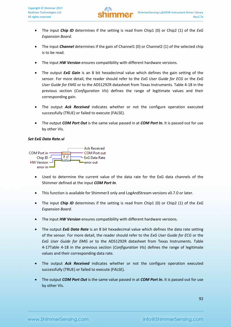
Copyright © Shimmer 2017
Realtime Technologies Ltd ShimmerSensing LabVIEW Instrument Driver Library
All rights reserved Rev2.7a
92
The input Chip ID determines if the setting is read from Chip1 (0) or Chip2 (1) of the ExG
Expansion Board.
The input Channel determines if the gain of Channel1 (0) or Channel2 (1) of the selected chip
is to be read.
The input HW Version ensures compatibility with different hardware versions.
The output ExG Gain is an 8 bit hexadecimal value which defines the gain setting of the
sensor. For more detail, the reader should refer to the ExG User Guide for ECG or the ExG
User Guide for EMG or to the ADS1292R datasheet from Texas Instruments. Table 4-18 in the
previous section (Configuration VIs) defines the range of legitimate values and their
corresponding gain.
The output Ack Received indicates whether or not the configure operation executed
successfully (TRUE) or failed to execute (FALSE).
The output COM Port Out is the same value passed in at COM Port In. It is passed out for use
by other VIs.
Set ExG Data Rate.vi
Used to determine the current value of the data rate for the ExG data channels of the
Shimmer defined at the input COM Port In.
This function is available for Shimmer3 only and LogAndStream versions v0.7.0 or later.
The input Chip ID determines if the setting is read from Chip1 (0) or Chip2 (1) of the ExG
Expansion Board.
The input HW Version ensures compatibility with different hardware versions.
The output ExG Data Rate is an 8 bit hexadecimal value which defines the data rate setting
of the sensor. For more detail, the reader should refer to the ExG User Guide for ECG or the
ExG User Guide for EMG or to the ADS1292R datasheet from Texas Instruments. Table
4-17Table 4-18 in the previous section (Configuration VIs) defines the range of legitimate
values and their corresponding data rate.
The output Ack Received indicates whether or not the configure operation executed
successfully (TRUE) or failed to execute (FALSE).
The output COM Port Out is the same value passed in at COM Port In. It is passed out for use
by other VIs.
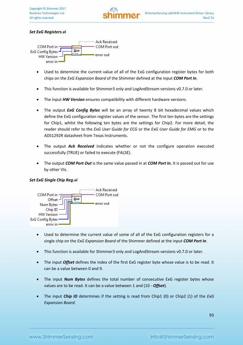
Copyright © Shimmer 2017
Realtime Technologies Ltd ShimmerSensing LabVIEW Instrument Driver Library
All rights reserved Rev2.7a
93
Set ExG Registers.vi
Used to determine the current value of all of the ExG configuration register bytes for both
chips on the ExG Expansion Board of the Shimmer defined at the input COM Port In.
This function is available for Shimmer3 only and LogAndStream versions v0.7.0 or later.
The input HW Version ensures compatibility with different hardware versions.
The output ExG Config Bytes will be an array of twenty 8 bit hexadecimal values which
define the ExG configuration register values of the sensor. The first ten bytes are the settings
for Chip1, whilst the following ten bytes are the settings for Chip2. For more detail, the
reader should refer to the ExG User Guide for ECG or the ExG User Guide for EMG or to the
ADS1292R datasheet from Texas Instruments.
The output Ack Received indicates whether or not the configure operation executed
successfully (TRUE) or failed to execute (FALSE).
The output COM Port Out is the same value passed in at COM Port In. It is passed out for use
by other VIs.
Set ExG Single Chip Reg.vi
Used to determine the current value of some of all of the ExG configuration registers for a
single chip on the ExG Expansion Board of the Shimmer defined at the input COM Port In.
This function is available for Shimmer3 only and LogAndStream versions v0.7.0 or later.
The input Offset defines the index of the first ExG register byte whose value is to be read. It
can be a value between 0 and 9.
The input Num Bytes defines the total number of consecutive ExG register bytes whose
values are to be read. It can be a value between 1 and (10 - Offset).
The input Chip ID determines if the setting is read from Chip1 (0) or Chip2 (1) of the ExG
Expansion Board.
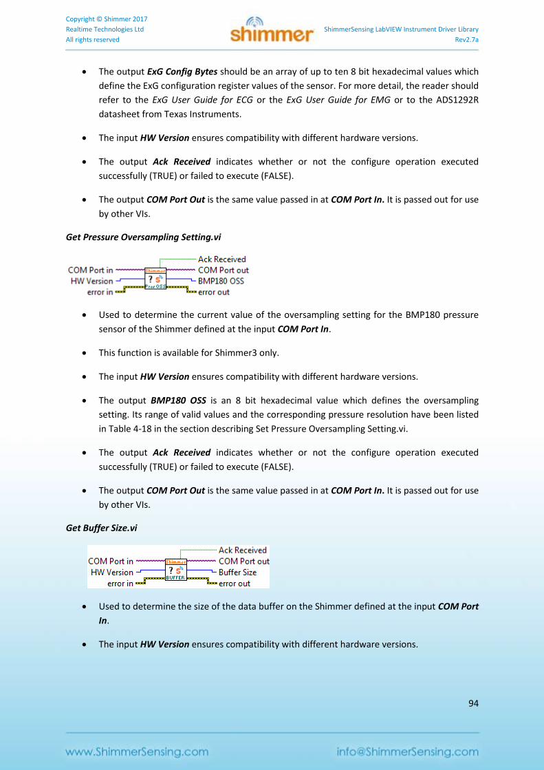
Copyright © Shimmer 2017
Realtime Technologies Ltd ShimmerSensing LabVIEW Instrument Driver Library
All rights reserved Rev2.7a
94
The output ExG Config Bytes should be an array of up to ten 8 bit hexadecimal values which
define the ExG configuration register values of the sensor. For more detail, the reader should
refer to the ExG User Guide for ECG or the ExG User Guide for EMG or to the ADS1292R
datasheet from Texas Instruments.
The input HW Version ensures compatibility with different hardware versions.
The output Ack Received indicates whether or not the configure operation executed
successfully (TRUE) or failed to execute (FALSE).
The output COM Port Out is the same value passed in at COM Port In. It is passed out for use
by other VIs.
Get Pressure Oversampling Setting.vi
Used to determine the current value of the oversampling setting for the BMP180 pressure
sensor of the Shimmer defined at the input COM Port In.
This function is available for Shimmer3 only.
The input HW Version ensures compatibility with different hardware versions.
The output BMP180 OSS is an 8 bit hexadecimal value which defines the oversampling
setting. Its range of valid values and the corresponding pressure resolution have been listed
in Table 4-18 in the section describing Set Pressure Oversampling Setting.vi.
The output Ack Received indicates whether or not the configure operation executed
successfully (TRUE) or failed to execute (FALSE).
The output COM Port Out is the same value passed in at COM Port In. It is passed out for use
by other VIs.
Get Buffer Size.vi
Used to determine the size of the data buffer on the Shimmer defined at the input COM Port
In.
The input HW Version ensures compatibility with different hardware versions.
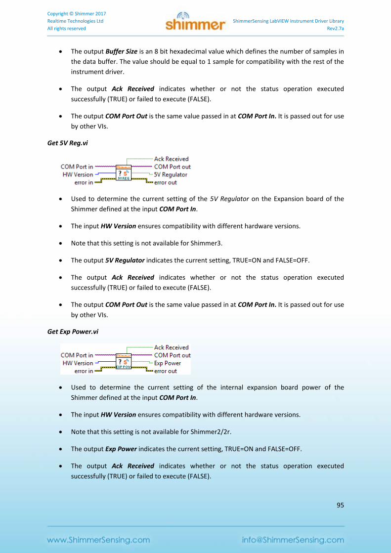
Copyright © Shimmer 2017
Realtime Technologies Ltd ShimmerSensing LabVIEW Instrument Driver Library
All rights reserved Rev2.7a
95
The output Buffer Size is an 8 bit hexadecimal value which defines the number of samples in
the data buffer. The value should be equal to 1 sample for compatibility with the rest of the
instrument driver.
The output Ack Received indicates whether or not the status operation executed
successfully (TRUE) or failed to execute (FALSE).
The output COM Port Out is the same value passed in at COM Port In. It is passed out for use
by other VIs.
Get 5V Reg.vi
Used to determine the current setting of the 5V Regulator on the Expansion board of the
Shimmer defined at the input COM Port In.
The input HW Version ensures compatibility with different hardware versions.
Note that this setting is not available for Shimmer3.
The output 5V Regulator indicates the current setting, TRUE=ON and FALSE=OFF.
The output Ack Received indicates whether or not the status operation executed
successfully (TRUE) or failed to execute (FALSE).
The output COM Port Out is the same value passed in at COM Port In. It is passed out for use
by other VIs.
Get Exp Power.vi
Used to determine the current setting of the internal expansion board power of the
Shimmer defined at the input COM Port In.
The input HW Version ensures compatibility with different hardware versions.
Note that this setting is not available for Shimmer2/2r.
The output Exp Power indicates the current setting, TRUE=ON and FALSE=OFF.
The output Ack Received indicates whether or not the status operation executed
successfully (TRUE) or failed to execute (FALSE).
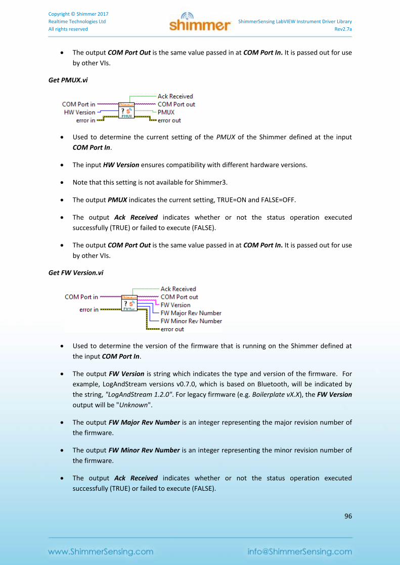
Copyright © Shimmer 2017
Realtime Technologies Ltd ShimmerSensing LabVIEW Instrument Driver Library
All rights reserved Rev2.7a
96
The output COM Port Out is the same value passed in at COM Port In. It is passed out for use
by other VIs.
Get PMUX.vi
Used to determine the current setting of the PMUX of the Shimmer defined at the input
COM Port In.
The input HW Version ensures compatibility with different hardware versions.
Note that this setting is not available for Shimmer3.
The output PMUX indicates the current setting, TRUE=ON and FALSE=OFF.
The output Ack Received indicates whether or not the status operation executed
successfully (TRUE) or failed to execute (FALSE).
The output COM Port Out is the same value passed in at COM Port In. It is passed out for use
by other VIs.
Get FW Version.vi
Used to determine the version of the firmware that is running on the Shimmer defined at
the input COM Port In.
The output FW Version is string which indicates the type and version of the firmware. For
example, LogAndStream versions v0.7.0, which is based on Bluetooth, will be indicated by
the string, "LogAndStream 1.2.0". For legacy firmware (e.g. Boilerplate vX.X), the FW Version
output will be "Unknown".
The output FW Major Rev Number is an integer representing the major revision number of
the firmware.
The output FW Minor Rev Number is an integer representing the minor revision number of
the firmware.
The output Ack Received indicates whether or not the status operation executed
successfully (TRUE) or failed to execute (FALSE).
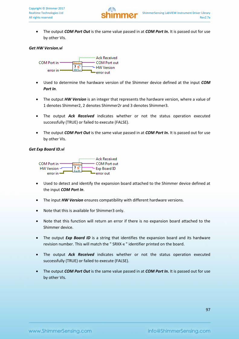
Copyright © Shimmer 2017
Realtime Technologies Ltd ShimmerSensing LabVIEW Instrument Driver Library
All rights reserved Rev2.7a
97
The output COM Port Out is the same value passed in at COM Port In. It is passed out for use
by other VIs.
Get HW Version.vi
Used to determine the hardware version of the Shimmer device defined at the input COM
Port In.
The output HW Version is an integer that represents the hardware version, where a value of
1 denotes Shimmer2, 2 denotes Shimmer2r and 3 denotes Shimmer3.
The output Ack Received indicates whether or not the status operation executed
successfully (TRUE) or failed to execute (FALSE).
The output COM Port Out is the same value passed in at COM Port In. It is passed out for use
by other VIs.
Get Exp Board ID.vi
Used to detect and identify the expansion board attached to the Shimmer device defined at
the input COM Port In.
The input HW Version ensures compatibility with different hardware versions.
Note that this is available for Shimmer3 only.
Note that this function will return an error if there is no expansion board attached to the
Shimmer device.
The output Exp Board ID is a string that identifies the expansion board and its hardware
revision number. This will match the " SRXX-x " identifier printed on the board.
The output Ack Received indicates whether or not the status operation executed
successfully (TRUE) or failed to execute (FALSE).
The output COM Port Out is the same value passed in at COM Port In. It is passed out for use
by other VIs.
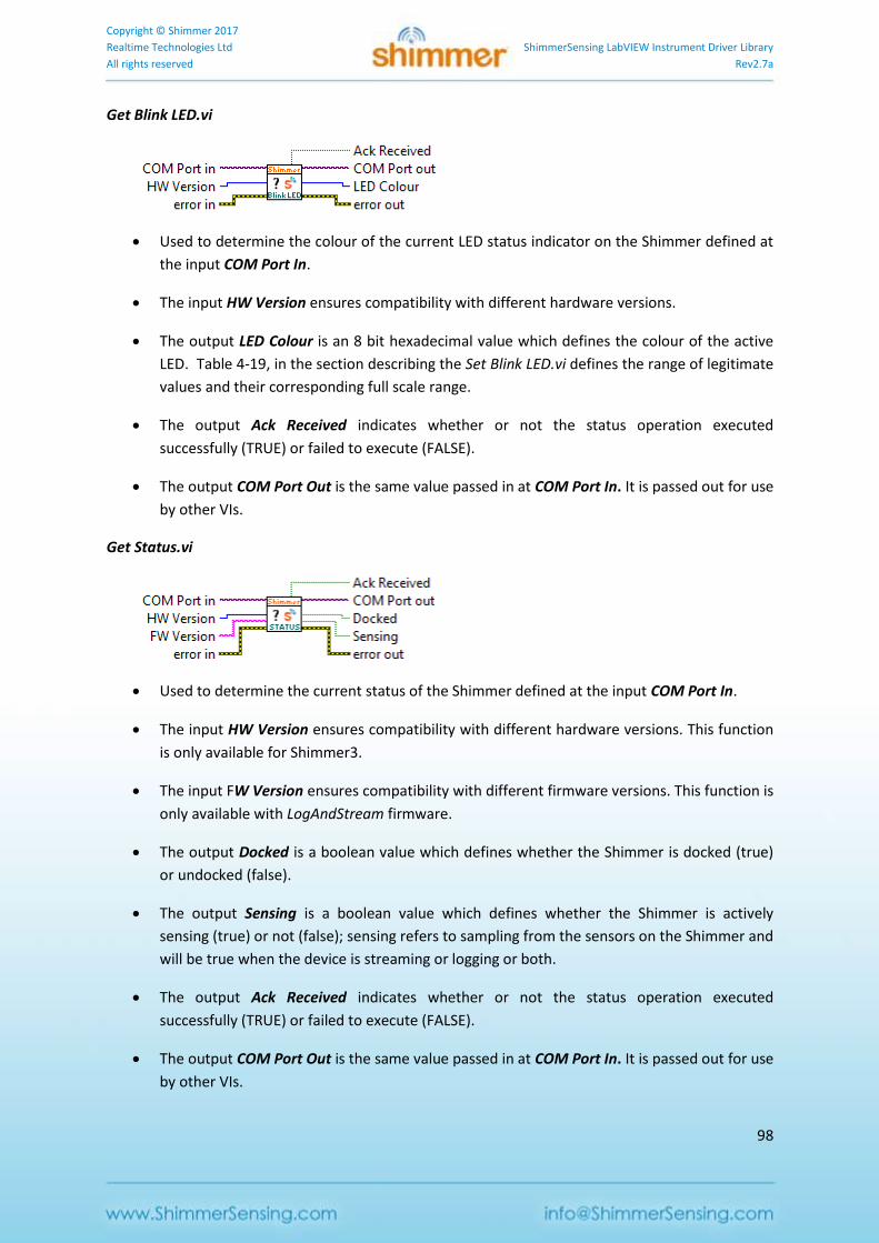
Copyright © Shimmer 2017
Realtime Technologies Ltd ShimmerSensing LabVIEW Instrument Driver Library
All rights reserved Rev2.7a
98
Get Blink LED.vi
Used to determine the colour of the current LED status indicator on the Shimmer defined at
the input COM Port In.
The input HW Version ensures compatibility with different hardware versions.
The output LED Colour is an 8 bit hexadecimal value which defines the colour of the active
LED. Table 4-19, in the section describing the Set Blink LED.vi defines the range of legitimate
values and their corresponding full scale range.
The output Ack Received indicates whether or not the status operation executed
successfully (TRUE) or failed to execute (FALSE).
The output COM Port Out is the same value passed in at COM Port In. It is passed out for use
by other VIs.
Get Status.vi
Used to determine the current status of the Shimmer defined at the input COM Port In.
The input HW Version ensures compatibility with different hardware versions. This function
is only available for Shimmer3.
The input FW Version ensures compatibility with different firmware versions. This function is
only available with LogAndStream firmware.
The output Docked is a boolean value which defines whether the Shimmer is docked (true)
or undocked (false).
The output Sensing is a boolean value which defines whether the Shimmer is actively
sensing (true) or not (false); sensing refers to sampling from the sensors on the Shimmer and
will be true when the device is streaming or logging or both.
The output Ack Received indicates whether or not the status operation executed
successfully (TRUE) or failed to execute (FALSE).
The output COM Port Out is the same value passed in at COM Port In. It is passed out for use
by other VIs.
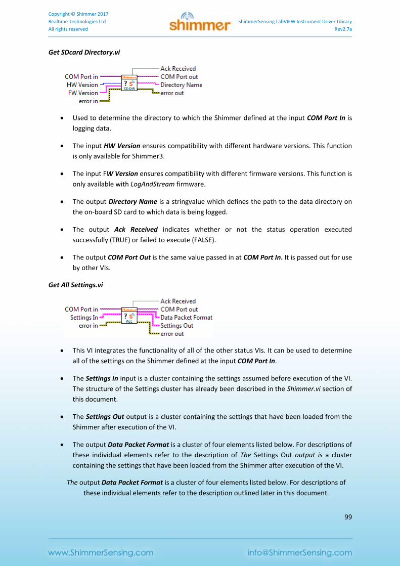
Copyright © Shimmer 2017
Realtime Technologies Ltd ShimmerSensing LabVIEW Instrument Driver Library
All rights reserved Rev2.7a
99
Get SDcard Directory.vi
Used to determine the directory to which the Shimmer defined at the input COM Port In is
logging data.
The input HW Version ensures compatibility with different hardware versions. This function
is only available for Shimmer3.
The input FW Version ensures compatibility with different firmware versions. This function is
only available with LogAndStream firmware.
The output Directory Name is a stringvalue which defines the path to the data directory on
the on-board SD card to which data is being logged.
The output Ack Received indicates whether or not the status operation executed
successfully (TRUE) or failed to execute (FALSE).
The output COM Port Out is the same value passed in at COM Port In. It is passed out for use
by other VIs.
Get All Settings.vi
This VI integrates the functionality of all of the other status VIs. It can be used to determine
all of the settings on the Shimmer defined at the input COM Port In.
The Settings In input is a cluster containing the settings assumed before execution of the VI.
The structure of the Settings cluster has already been described in the Shimmer.vi section of
this document.
The Settings Out output is a cluster containing the settings that have been loaded from the
Shimmer after execution of the VI.
The output Data Packet Format is a cluster of four elements listed below. For descriptions of
these individual elements refer to the description of The Settings Out output is a cluster
containing the settings that have been loaded from the Shimmer after execution of the VI.
The output Data Packet Format is a cluster of four elements listed below. For descriptions of
these individual elements refer to the description outlined later in this document.
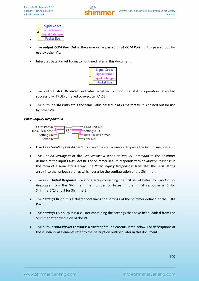
Copyright © Shimmer 2017
Realtime Technologies Ltd ShimmerSensing LabVIEW Instrument Driver Library
All rights reserved Rev2.7a
100
The output COM Port Out is the same value passed in at COM Port In. It is passed out for
use by other VIs.
Interpret Data Packet Format.vi outlined later in this document.
The output Ack Received indicates whether or not the status operation executed
successfully (TRUE) or failed to execute (FALSE).
The output COM Port Out is the same value passed in at COM Port In. It is passed out for use
by other VIs.
Parse Inquiry Response.vi
Used as a SubVI by Get All Settings.vi and the Get Sensors.vi to parse the Inquiry Response.
The Get All Settings.vi or the Get Sensors.vi sends an Inquiry Command to the Shimmer
defined at the input COM Port In. The Shimmer in-turn responds with an Inquiry Response in
the form of a serial string array. The Parse Inquiry Response.vi translates the serial string
array into the various settings which describe the configuration of the Shimmer.
The input Initial Response is a string array containing the first set of bytes from an Inquiry
Response from the Shimmer. The number of bytes in the initial response is 6 for
Shimmer2/2r and 9 for Shimmer3.
The Settings In input is a cluster containing the settings of the Shimmer defined at the COM
Port.
The Settings Out output is a cluster containing the settings that have been loaded from the
Shimmer after execution of the VI.
The output Data Packet Format is a cluster of four elements listed below. For descriptions of
these individual elements refer to the description outlined later in this document.
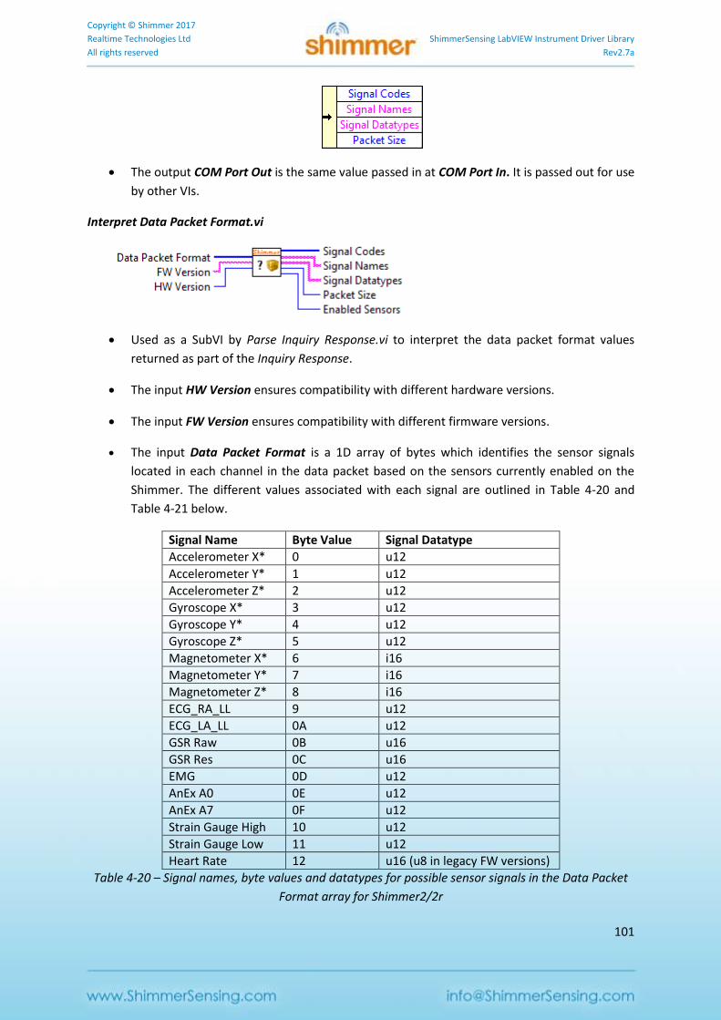
Copyright © Shimmer 2017
Realtime Technologies Ltd ShimmerSensing LabVIEW Instrument Driver Library
All rights reserved Rev2.7a
101
The output COM Port Out is the same value passed in at COM Port In. It is passed out for use
by other VIs.
Interpret Data Packet Format.vi
Used as a SubVI by Parse Inquiry Response.vi to interpret the data packet format values
returned as part of the Inquiry Response.
The input HW Version ensures compatibility with different hardware versions.
The input FW Version ensures compatibility with different firmware versions.
The input Data Packet Format is a 1D array of bytes which identifies the sensor signals
located in each channel in the data packet based on the sensors currently enabled on the
Shimmer. The different values associated with each signal are outlined in Table 4-20 and
Table 4-21 below.
Signal Name Byte Value Signal Datatype
Accelerometer X* 0 u12
Accelerometer Y* 1 u12
Accelerometer Z* 2 u12
Gyroscope X* 3 u12
Gyroscope Y* 4 u12
Gyroscope Z* 5 u12
Magnetometer X* 6 i16
Magnetometer Y* 7 i16
Magnetometer Z* 8 i16
ECG_RA_LL 9 u12
ECG_LA_LL 0A u12
GSR Raw 0B u16
GSR Res 0C u16
EMG 0D u12
AnEx A0 0E u12
AnEx A7 0F u12
Strain Gauge High 10 u12
Strain Gauge Low 11 u12
Heart Rate 12 u16 (u8 in legacy FW versions)
Table 4-20 – Signal names, byte values and datatypes for possible sensor signals in the Data Packet
Format array for Shimmer2/2r
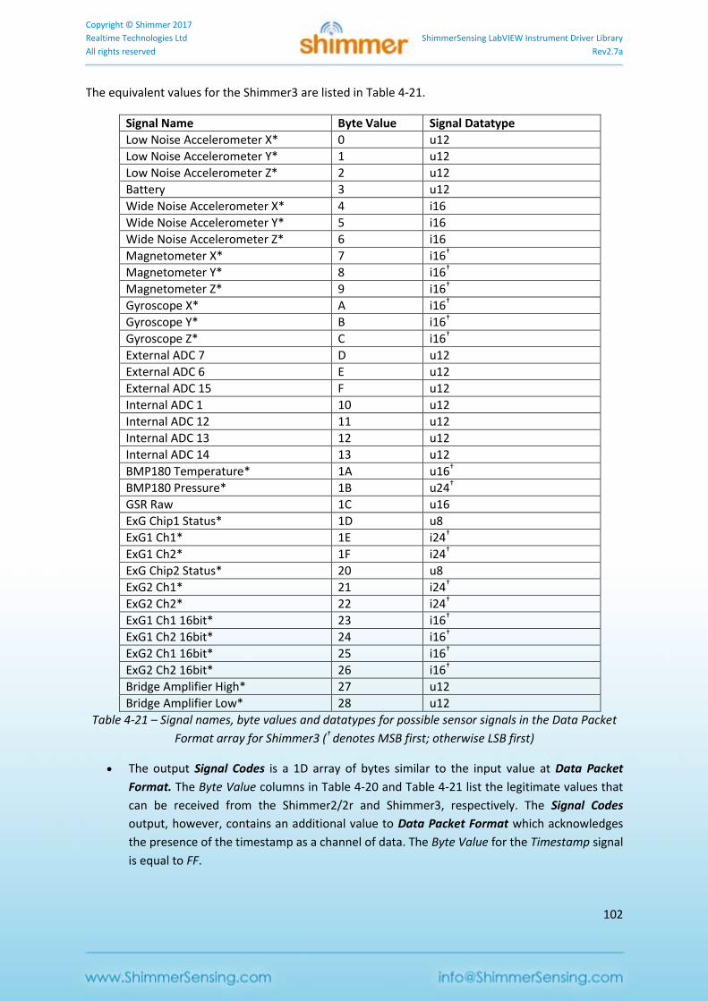
Copyright © Shimmer 2017
Realtime Technologies Ltd ShimmerSensing LabVIEW Instrument Driver Library
All rights reserved Rev2.7a
102
The equivalent values for the Shimmer3 are listed in Table 4-21.
Signal Name Byte Value Signal Datatype
Low Noise Accelerometer X* 0 u12
Low Noise Accelerometer Y* 1 u12
Low Noise Accelerometer Z* 2 u12
Battery 3 u12
Wide Noise Accelerometer X* 4 i16
Wide Noise Accelerometer Y* 5 i16
Wide Noise Accelerometer Z* 6 i16
Magnetometer X* 7 i16†
Magnetometer Y* 8 i16†
Magnetometer Z* 9 i16†
Gyroscope X* A i16†
Gyroscope Y* B i16†
Gyroscope Z* C i16†
External ADC 7 D u12
External ADC 6 E u12
External ADC 15 F u12
Internal ADC 1 10 u12
Internal ADC 12 11 u12
Internal ADC 13 12 u12
Internal ADC 14 13 u12
BMP180 Temperature* 1A u16†
BMP180 Pressure* 1B u24†
GSR Raw 1C u16
ExG Chip1 Status* 1D u8
ExG1 Ch1* 1E i24†
ExG1 Ch2* 1F i24†
ExG Chip2 Status* 20 u8
ExG2 Ch1* 21 i24†
ExG2 Ch2* 22 i24†
ExG1 Ch1 16bit* 23 i16†
ExG1 Ch2 16bit* 24 i16†
ExG2 Ch1 16bit* 25 i16†
ExG2 Ch2 16bit* 26 i16†
Bridge Amplifier High* 27 u12
Bridge Amplifier Low* 28 u12
Table 4-21 – Signal names, byte values and datatypes for possible sensor signals in the Data Packet
Format array for Shimmer3 († denotes MSB first; otherwise LSB first)
The output Signal Codes is a 1D array of bytes similar to the input value at Data Packet
Format. The Byte Value columns in Table 4-20 and Table 4-21 list the legitimate values that
can be received from the Shimmer2/2r and Shimmer3, respectively. The Signal Codes
output, however, contains an additional value to Data Packet Format which acknowledges
the presence of the timestamp as a channel of data. The Byte Value for the Timestamp signal
is equal to FF.
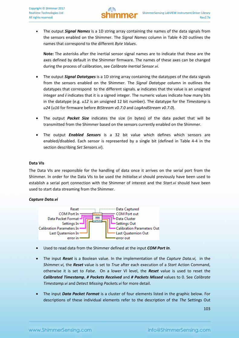
Copyright © Shimmer 2017
Realtime Technologies Ltd ShimmerSensing LabVIEW Instrument Driver Library
All rights reserved Rev2.7a
103
The output Signal Names is a 1D string array containing the names of the data signals from
the sensors enabled on the Shimmer. The Signal Names column in Table 4-20 outlines the
names that correspond to the different Byte Values.
Note: The asterisks after the inertial sensor signal names are to indicate that these are the
axes defined by default in the Shimmer firmware. The names of these axes can be changed
during the process of calibration, see Calibrate Inertial Sensor.vi.
The output Signal Datatypes is a 1D string array containing the datatypes of the data signals
from the sensors enabled on the Shimmer. The Signal Datatype column in outlines the
datatypes that correspond to the different signals. u indicates that the value is an unsigned
integer and i indicates that it is a signed integer. The numeric values indicate how many bits
in the datatype (e.g. u12 is an unsigned 12 bit number). The datatype for the Timestamp is
u24 (u16 for firmware before BtStream v0.7.0 and LogAndStream v0.7.0).
The output Packet Size indicates the size (in bytes) of the data packet that will be
transmitted from the Shimmer based on the sensors currently enabled on the Shimmer.
The output Enabled Sensors is a 32 bit value which defines which sensors are
enabled/disabled. Each sensor is represented by a single bit (defined in Table 4-4 in the
section describing Set Sensors.vi).
Data VIs
The Data VIs are responsible for the handling of data once it arrives on the serial port from the
Shimmer. In order for the Data VIs to be used the Initialise.vi should previously have been used to
establish a serial port connection with the Shimmer of interest and the Start.vi should have been
used to start data streaming from the Shimmer.
Capture Data.vi
Used to read data from the Shimmer defined at the input COM Port In.
The input Reset is a Boolean value. In the implementation of the Capture Data.vi, in the
Shimmer.vi, the Reset value is set to True after each execution of a Start Action Command,
otherwise it is set to False. On a lower VI level, the Reset value is used to reset the
Calibrated Timestamp, # Packets Received and # Packets Missed values to 0. See Calibrate
Timestamp.vi and Detect Missing Packets.vi for more detail.
The input Data Packet Format is a cluster of four elements listed in the graphic below. For
descriptions of these individual elements refer to the description of the The Settings Out
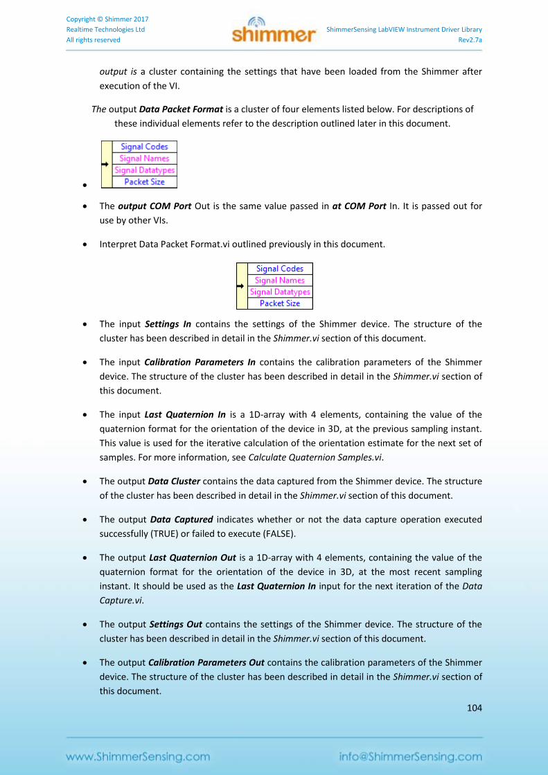
Copyright © Shimmer 2017
Realtime Technologies Ltd ShimmerSensing LabVIEW Instrument Driver Library
All rights reserved Rev2.7a
104
output is a cluster containing the settings that have been loaded from the Shimmer after
execution of the VI.
The output Data Packet Format is a cluster of four elements listed below. For descriptions of
these individual elements refer to the description outlined later in this document.
The output COM Port Out is the same value passed in at COM Port In. It is passed out for
use by other VIs.
Interpret Data Packet Format.vi outlined previously in this document.
The input Settings In contains the settings of the Shimmer device. The structure of the
cluster has been described in detail in the Shimmer.vi section of this document.
The input Calibration Parameters In contains the calibration parameters of the Shimmer
device. The structure of the cluster has been described in detail in the Shimmer.vi section of
this document.
The input Last Quaternion In is a 1D-array with 4 elements, containing the value of the
quaternion format for the orientation of the device in 3D, at the previous sampling instant.
This value is used for the iterative calculation of the orientation estimate for the next set of
samples. For more information, see Calculate Quaternion Samples.vi.
The output Data Cluster contains the data captured from the Shimmer device. The structure
of the cluster has been described in detail in the Shimmer.vi section of this document.
The output Data Captured indicates whether or not the data capture operation executed
successfully (TRUE) or failed to execute (FALSE).
The output Last Quaternion Out is a 1D-array with 4 elements, containing the value of the
quaternion format for the orientation of the device in 3D, at the most recent sampling
instant. It should be used as the Last Quaternion In input for the next iteration of the Data
Capture.vi.
The output Settings Out contains the settings of the Shimmer device. The structure of the
cluster has been described in detail in the Shimmer.vi section of this document.
The output Calibration Parameters Out contains the calibration parameters of the Shimmer
device. The structure of the cluster has been described in detail in the Shimmer.vi section of
this document.
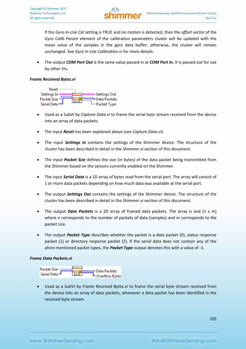
Copyright © Shimmer 2017
Realtime Technologies Ltd ShimmerSensing LabVIEW Instrument Driver Library
All rights reserved Rev2.7a
105
If the Gyro In-Use Cal setting is TRUE and no motion is detected, then the offset vector of the
Gyro Calib Param element of the calibration parameters cluster will be updated with the
mean value of the samples in the gyro data buffer; otherwise, the cluster will remain
unchanged. See Gyro In-Use Calibration.vi for more details.
The output COM Port Out is the same value passed in at COM Port In. It is passed out for use
by other VIs.
Frame Received Bytes.vi
Used as a SubVI by Capture Data.vi to frame the serial byte stream received from the device
into an array of data packets.
The input Reset has been explained above (see Capture Data.vi).
The input Settings In contains the settings of the Shimmer device. The structure of the
cluster has been described in detail in the Shimmer.vi section of this document.
The input Packet Size defines the size (in bytes) of the data packet being transmitted from
the Shimmer based on the sensors currently enabled on the Shimmer.
The input Serial Data is a 1D array of bytes read from the serial port. The array will consist of
1 or more data packets depending on how much data was available at the serial port.
The output Settings Out contains the settings of the Shimmer device. The structure of the
cluster has been described in detail in the Shimmer.vi section of this document.
The output Data Packets is a 2D array of framed data packets. The array is and [n x m]
where n corresponds to the number of packets of data (samples) and m corresponds to the
packet size.
The output Packet Type describes whether the packet is a data packet (0), status response
packet (1) or directory response packet (2). If the serial data does not contain any of the
afore-mentioned packet types, the Packet Type output denotes this with a value of -1.
Frame Data Packets.vi
Used as a SubVI by Frame Received Bytes.vi to frame the serial byte stream received from
the device into an array of data packets, whenever a data packet has been identified in the
received byte stream.

Copyright © Shimmer 2017
Realtime Technologies Ltd ShimmerSensing LabVIEW Instrument Driver Library
All rights reserved Rev2.7a
106
The input Packet Size defines the size (in bytes) of the data packet being transmitted from
the Shimmer based on the sensors currently enabled on the Shimmer.
The input Serial Data is a 1D array of bytes read from the serial port. The array will consist of
1 or more data packets depending on how much data was available at the serial port.
The output Data Packets is a 2D array of framed data packets. The array is an [n x m] array
where n corresponds to the number of packets of data (samples) and m corresponds to the
packet size.
The output Overflow Bytes contains any surplus bytes that have been received at the serial
port; for example, they may contain a partial data packet, status response packet or
directory response packet. Any bytes received at the next iteration of the VI will be
appended after the overflow bytes from the current iteration.
Parse Instream Response Bytes.vi
Used as a SubVI by Frame Received Bytes.vi to parse the serial byte stream received from the
device, whenever a so-called "in-stream response" packet has been identified in the
received byte stream. In-stream response packets can contain information about the device
status (status response packet) or the SDcard directory name (directory response packet).
The input Serial Data is a 1D array of bytes read from the serial port. The array will consist of
1 or more data packets depending on how much data was available at the serial port.
The output Data Packets is a 2D array of framed data packets. The array is an [n x m] array
where n corresponds to the number of packets of data (samples) and m corresponds to the
packet size.
The output Packet Type describes whether the packet is a status response packet (1) or
directory response packet (2). If the serial data does not contain either of the afore-
mentioned packet types, the Packet Type output denotes this with a value of -1.
The output Overflow Bytes contains any surplus bytes that have been received at the serial
port; for example, they may contain a partial data packet, status response packet or
directory response packet. Any bytes received at the next iteration of the VI will be
appended after the overflow bytes from the current iteration.
Parse Data.vi
Used as a SubVI by Capture Data.vi to parse the array of data packets into an array of
uncalibrated sensor data.
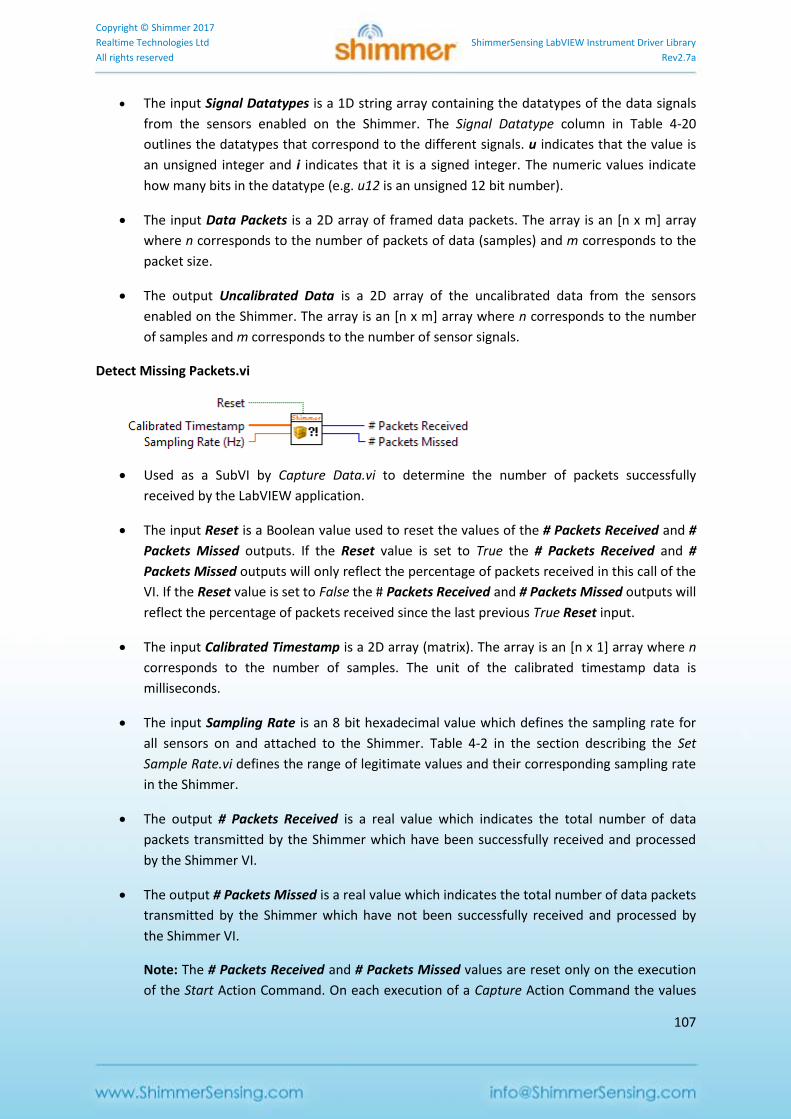
Copyright © Shimmer 2017
Realtime Technologies Ltd ShimmerSensing LabVIEW Instrument Driver Library
All rights reserved Rev2.7a
107
The input Signal Datatypes is a 1D string array containing the datatypes of the data signals
from the sensors enabled on the Shimmer. The Signal Datatype column in Table 4-20
outlines the datatypes that correspond to the different signals. u indicates that the value is
an unsigned integer and i indicates that it is a signed integer. The numeric values indicate
how many bits in the datatype (e.g. u12 is an unsigned 12 bit number).
The input Data Packets is a 2D array of framed data packets. The array is an [n x m] array
where n corresponds to the number of packets of data (samples) and m corresponds to the
packet size.
The output Uncalibrated Data is a 2D array of the uncalibrated data from the sensors
enabled on the Shimmer. The array is an [n x m] array where n corresponds to the number
of samples and m corresponds to the number of sensor signals.
Detect Missing Packets.vi
Used as a SubVI by Capture Data.vi to determine the number of packets successfully
received by the LabVIEW application.
The input Reset is a Boolean value used to reset the values of the # Packets Received and #
Packets Missed outputs. If the Reset value is set to True the # Packets Received and #
Packets Missed outputs will only reflect the percentage of packets received in this call of the
VI. If the Reset value is set to False the # Packets Received and # Packets Missed outputs will
reflect the percentage of packets received since the last previous True Reset input.
The input Calibrated Timestamp is a 2D array (matrix). The array is an [n x 1] array where n
corresponds to the number of samples. The unit of the calibrated timestamp data is
milliseconds.
The input Sampling Rate is an 8 bit hexadecimal value which defines the sampling rate for
all sensors on and attached to the Shimmer. Table 4-2 in the section describing the Set
Sample Rate.vi defines the range of legitimate values and their corresponding sampling rate
in the Shimmer.
The output # Packets Received is a real value which indicates the total number of data
packets transmitted by the Shimmer which have been successfully received and processed
by the Shimmer VI.
The output # Packets Missed is a real value which indicates the total number of data packets
transmitted by the Shimmer which have not been successfully received and processed by
the Shimmer VI.
Note: The # Packets Received and # Packets Missed values are reset only on the execution
of the Start Action Command. On each execution of a Capture Action Command the values
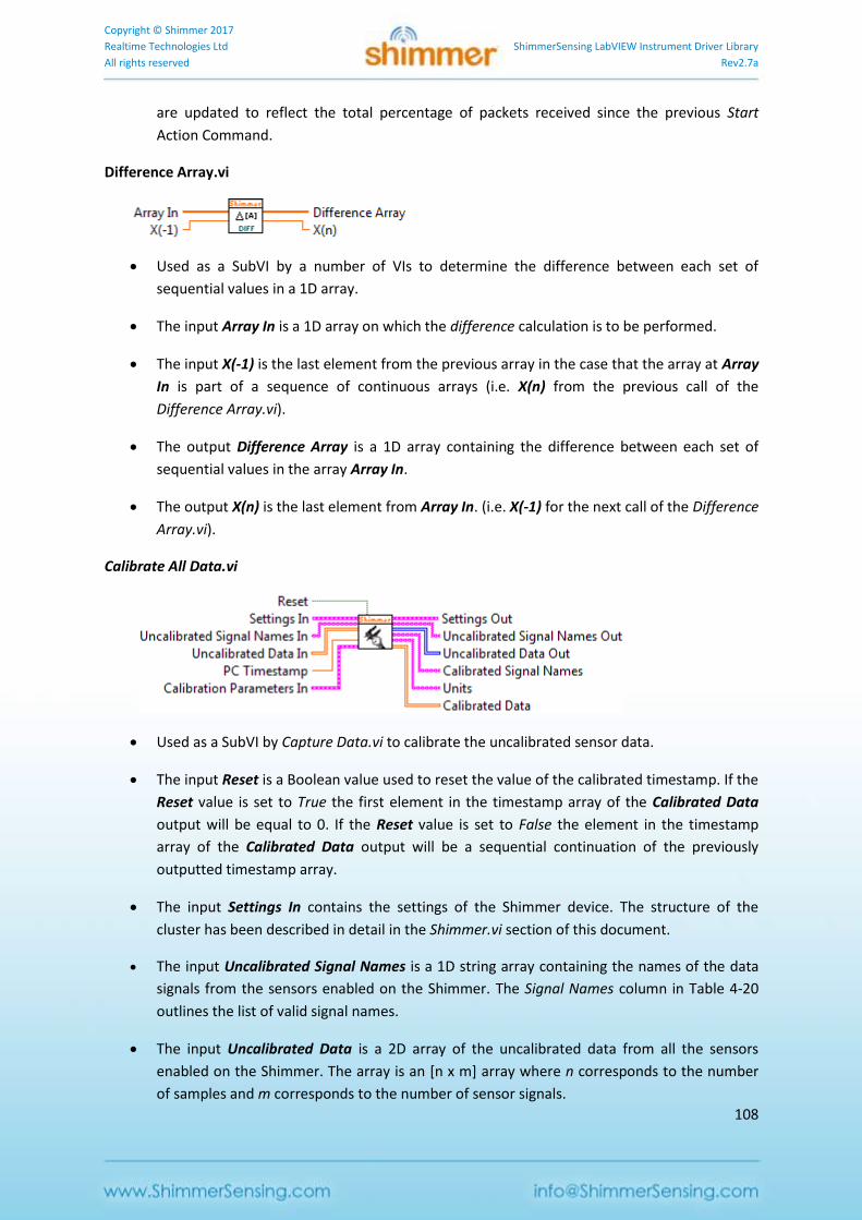
Copyright © Shimmer 2017
Realtime Technologies Ltd ShimmerSensing LabVIEW Instrument Driver Library
All rights reserved Rev2.7a
108
are updated to reflect the total percentage of packets received since the previous Start
Action Command.
Difference Array.vi
Used as a SubVI by a number of VIs to determine the difference between each set of
sequential values in a 1D array.
The input Array In is a 1D array on which the difference calculation is to be performed.
The input X(-1) is the last element from the previous array in the case that the array at Array
In is part of a sequence of continuous arrays (i.e. X(n) from the previous call of the
Difference Array.vi).
The output Difference Array is a 1D array containing the difference between each set of
sequential values in the array Array In.
The output X(n) is the last element from Array In. (i.e. X(-1) for the next call of the Difference
Array.vi).
Calibrate All Data.vi
Used as a SubVI by Capture Data.vi to calibrate the uncalibrated sensor data.
The input Reset is a Boolean value used to reset the value of the calibrated timestamp. If the
Reset value is set to True the first element in the timestamp array of the Calibrated Data
output will be equal to 0. If the Reset value is set to False the element in the timestamp
array of the Calibrated Data output will be a sequential continuation of the previously
outputted timestamp array.
The input Settings In contains the settings of the Shimmer device. The structure of the
cluster has been described in detail in the Shimmer.vi section of this document.
The input Uncalibrated Signal Names is a 1D string array containing the names of the data
signals from the sensors enabled on the Shimmer. The Signal Names column in Table 4-20
outlines the list of valid signal names.
The input Uncalibrated Data is a 2D array of the uncalibrated data from all the sensors
enabled on the Shimmer. The array is an [n x m] array where n corresponds to the number
of samples and m corresponds to the number of sensor signals.
Copyright © Shimmer 2017
Realtime Technologies Ltd ShimmerSensing LabVIEW Instrument Driver Library
All rights reserved Rev2.7a
109
The input PC Timestamp contains the time at which the data was received by LabVIEW from
the Bluetooth stack.
The input Calibration Parameters In contains the calibration parameters of the Shimmer
device. The structure of the cluster has been described in detail in the Shimmer.vi section of
this document.
The output Settings Out contains the settings of the Shimmer device. The structure of the
cluster has been described in detail in the Shimmer.vi section of this document.
The output Uncalibrated Signal Names Out is a 1D string array containing the names of the
data signals from the sensors enabled on the Shimmer. The Signal Names column in Table
4-20 outlines the list of valid signal names.
The output Uncalibrated Data is a 2D array of the uncalibrated data from all the sensors
enabled on the Shimmer. The array is an [n x m] array where n corresponds to the number
of samples and m corresponds to the number of sensor signals.
The output Calibrated Signal Names is a 1D string array containing the names of the
calibrated data signals.
The output Units is a 1D string array containing the units of the calibrated data signals.
Note: An asterisk after the Units indicates that default offset and gain values from the
sensor data sheet have been used to calibrate the sensor data (e.g. mVolts*).
To improve the accuracy of your data when using the inertial sensors (accelerometer,
gyroscope or magnetometer) it is recommended that you use the standalone Shimmer
9DOF Calibration application which is available for download from the Shimmer website.
The application supports the calibration of the inertial sensors and the storage of the
calibration parameters on the Shimmer. When calibration parameters have been stored on
the Shimmer the Calibrate All Data.vi will use the stored calibration parameters as opposed
to default calibration parameters.
Also, for the accelerometer the Units may be followed by double asterisks (e.g. m/s2**).
This indicates that the calibration parameters which have been stored on the Shimmer are
not valid parameters for the current Accelerometer Range setting. This can be rectified by
configuring the Accelerometer Range to the setting that it was in when it was calibrated or
by recalibrating the Shimmer (using the Shimmer 9DOF Calibration Application) with the
device configured to the desired Accelerometer Range.
The output Calibrated Data is a 2D array (matrix) of the calibrated data from all the sensors
enabled on the Shimmer. The array is an [n x m] array where n corresponds to the number
of samples and m corresponds to the number of sensor signals. The order of the columns of
data corresponds to the order of the values in Calibrated Signal Names.
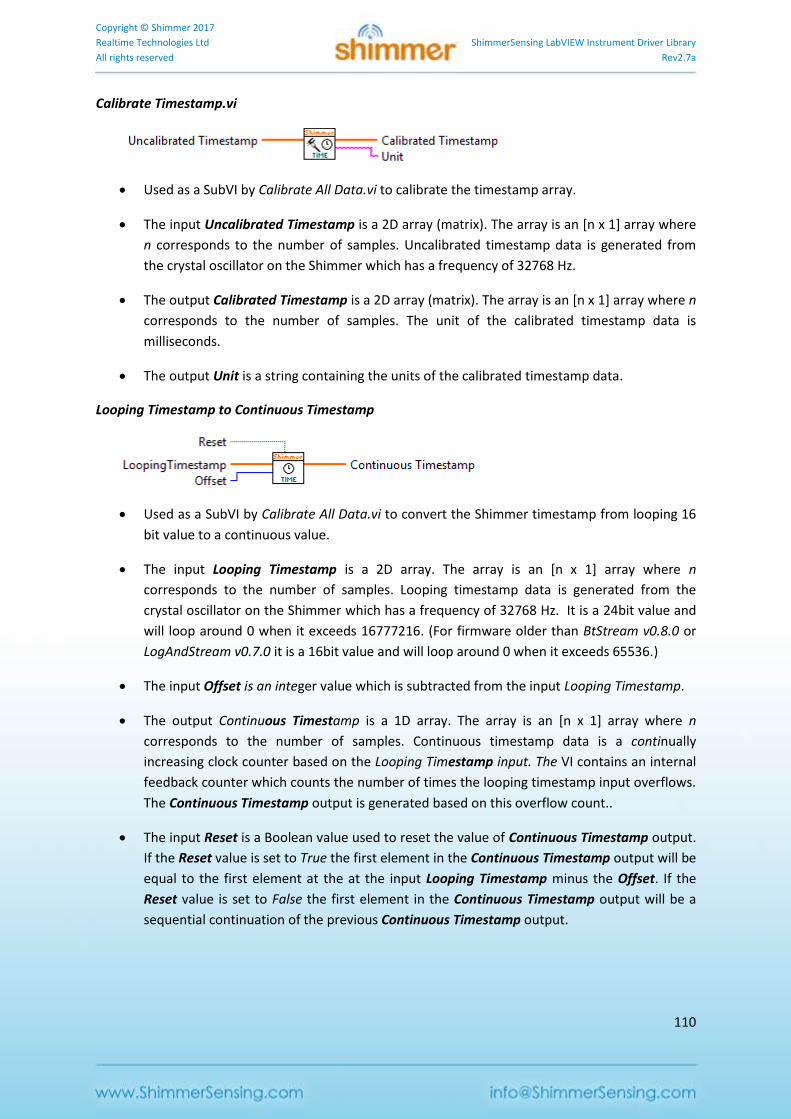
Copyright © Shimmer 2017
Realtime Technologies Ltd ShimmerSensing LabVIEW Instrument Driver Library
All rights reserved Rev2.7a
110
Calibrate Timestamp.vi
Used as a SubVI by Calibrate All Data.vi to calibrate the timestamp array.
The input Uncalibrated Timestamp is a 2D array (matrix). The array is an [n x 1] array where
n corresponds to the number of samples. Uncalibrated timestamp data is generated from
the crystal oscillator on the Shimmer which has a frequency of 32768 Hz.
The output Calibrated Timestamp is a 2D array (matrix). The array is an [n x 1] array where n
corresponds to the number of samples. The unit of the calibrated timestamp data is
milliseconds.
The output Unit is a string containing the units of the calibrated timestamp data.
Looping Timestamp to Continuous Timestamp
Used as a SubVI by Calibrate All Data.vi to convert the Shimmer timestamp from looping 16
bit value to a continuous value.
The input Looping Timestamp is a 2D array. The array is an [n x 1] array where n
corresponds to the number of samples. Looping timestamp data is generated from the
crystal oscillator on the Shimmer which has a frequency of 32768 Hz. It is a 24bit value and
will loop around 0 when it exceeds 16777216. (For firmware older than BtStream v0.8.0 or
LogAndStream v0.7.0 it is a 16bit value and will loop around 0 when it exceeds 65536.)
The input Offset is an integer value which is subtracted from the input Looping Timestamp.
The output Continuous Timestamp is a 1D array. The array is an [n x 1] array where n
corresponds to the number of samples. Continuous timestamp data is a continually
increasing clock counter based on the Looping Timestamp input. The VI contains an internal
feedback counter which counts the number of times the looping timestamp input overflows.
The Continuous Timestamp output is generated based on this overflow count..
The input Reset is a Boolean value used to reset the value of Continuous Timestamp output.
If the Reset value is set to True the first element in the Continuous Timestamp output will be
equal to the first element at the at the input Looping Timestamp minus the Offset. If the
Reset value is set to False the first element in the Continuous Timestamp output will be a
sequential continuation of the previous Continuous Timestamp output.
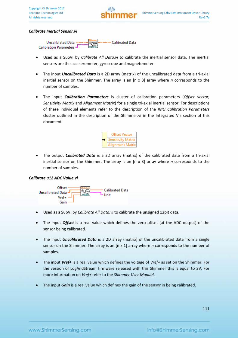
Copyright © Shimmer 2017
Realtime Technologies Ltd ShimmerSensing LabVIEW Instrument Driver Library
All rights reserved Rev2.7a
111
Calibrate Inertial Sensor.vi
Used as a SubVI by Calibrate All Data.vi to calibrate the inertial sensor data. The inertial
sensors are the accelerometer, gyroscope and magnetometer.
The input Uncalibrated Data is a 2D array (matrix) of the uncalibrated data from a tri-axial
inertial sensor on the Shimmer. The array is an [n x 3] array where n corresponds to the
number of samples.
The input Calibration Parameters is cluster of calibration parameters (Offset vector,
Sensitivity Matrix and Alignment Matrix) for a single tri-axial inertial sensor. For descriptions
of these individual elements refer to the description of the IMU Calibration Parameters
cluster outlined in the description of the Shimmer.vi in the Integrated VIs section of this
document.
The output Calibrated Data is a 2D array (matrix) of the calibrated data from a tri-axial
inertial sensor on the Shimmer. The array is an [n x 3] array where n corresponds to the
number of samples.
Calibrate u12 ADC Value.vi
Used as a SubVI by Calibrate All Data.vi to calibrate the unsigned 12bit data.
The input Offset is a real value which defines the zero offset (at the ADC output) of the
sensor being calibrated.
The input Uncalibrated Data is a 2D array (matrix) of the uncalibrated data from a single
sensor on the Shimmer. The array is an [n x 1] array where n corresponds to the number of
samples.
The input Vref+ is a real value which defines the voltage of Vref+ as set on the Shimmer. For
the version of LogAndStream firmware released with this Shimmer this is equal to 3V. For
more information on Vref+ refer to the Shimmer User Manual.
The input Gain is a real value which defines the gain of the sensor in being calibrated.

Copyright © Shimmer 2017
Realtime Technologies Ltd ShimmerSensing LabVIEW Instrument Driver Library
All rights reserved Rev2.7a
112
The output Calibrated Data is a 2D array (matrix) of the calibrated data from a single sensor
on the Shimmer. The array is an [n x 1] array where n corresponds to the number of
samples.
The output Unit is a string containing the units of the calibrated data signal.
Calibrate signed ADC Value.vi
Used as a SubVI by Calibrate All Data.vi to calibrate the signed n-bit data, where the number
of bits, n, is determined by one of the inputs.
The input Offset is a real value which defines the zero offset (at the ADC output) of the
sensor being calibrated.
The input Uncalibrated Data is a 2D array (matrix) of the uncalibrated data from a single
sensor on the Shimmer. The array is an [n x 1] array where n corresponds to the number of
samples.
The input Vref+ is a real value which defines the voltage of Vref+ as set on the Shimmer. This
value is 3V for most sensors, but can vary, e.g. 2.42V for ExG on Shimmer3. For more
information on Vref+ refer to the Shimmer User Manual and the user guides for the
expansion board that you are using; the value can be assumed to be 3V unless otherwise
mentioned.
The input Gain is a real value which defines the gain of the sensor in being calibrated.
The input Num Bits is a value which defines the number of bits in the data format (e.g., 8,
16, 24).
The output Calibrated Data is a 2D array (matrix) of the calibrated data from a single sensor
on the Shimmer. The array is an [n x 1] array where n corresponds to the number of
samples.
The output Unit is a string containing the units of the calibrated data signal.
Calibrate GSR.vi
Used as a SubVI by Calibrate All Data.vi to calibrate the data from the GSR sensor.
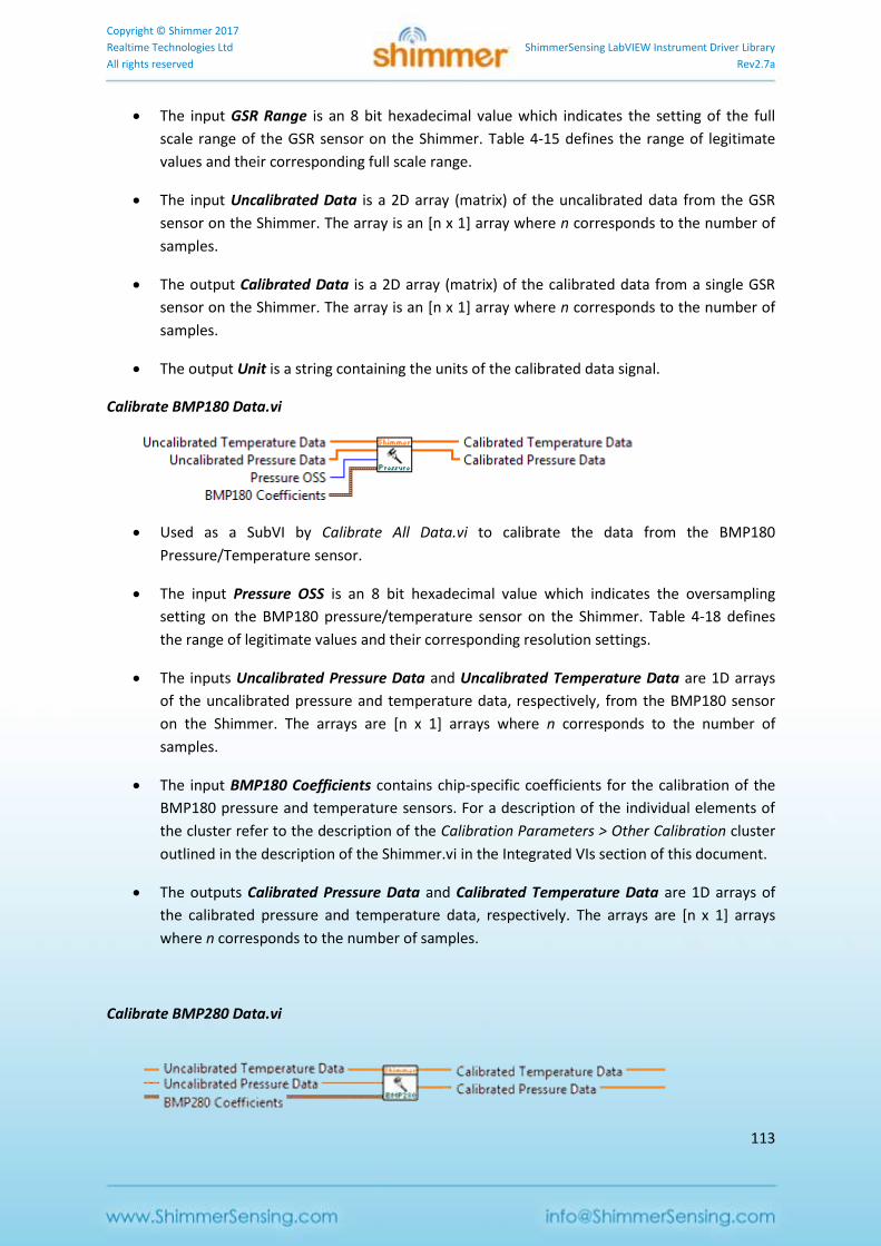
Copyright © Shimmer 2017
Realtime Technologies Ltd ShimmerSensing LabVIEW Instrument Driver Library
All rights reserved Rev2.7a
113
The input GSR Range is an 8 bit hexadecimal value which indicates the setting of the full
scale range of the GSR sensor on the Shimmer. Table 4-15 defines the range of legitimate
values and their corresponding full scale range.
The input Uncalibrated Data is a 2D array (matrix) of the uncalibrated data from the GSR
sensor on the Shimmer. The array is an [n x 1] array where n corresponds to the number of
samples.
The output Calibrated Data is a 2D array (matrix) of the calibrated data from a single GSR
sensor on the Shimmer. The array is an [n x 1] array where n corresponds to the number of
samples.
The output Unit is a string containing the units of the calibrated data signal.
Calibrate BMP180 Data.vi
Used as a SubVI by Calibrate All Data.vi to calibrate the data from the BMP180
Pressure/Temperature sensor.
The input Pressure OSS is an 8 bit hexadecimal value which indicates the oversampling
setting on the BMP180 pressure/temperature sensor on the Shimmer. Table 4-18 defines
the range of legitimate values and their corresponding resolution settings.
The inputs Uncalibrated Pressure Data and Uncalibrated Temperature Data are 1D arrays
of the uncalibrated pressure and temperature data, respectively, from the BMP180 sensor
on the Shimmer. The arrays are [n x 1] arrays where n corresponds to the number of
samples.
The input BMP180 Coefficients contains chip-specific coefficients for the calibration of the
BMP180 pressure and temperature sensors. For a description of the individual elements of
the cluster refer to the description of the Calibration Parameters > Other Calibration cluster
outlined in the description of the Shimmer.vi in the Integrated VIs section of this document.
The outputs Calibrated Pressure Data and Calibrated Temperature Data are 1D arrays of
the calibrated pressure and temperature data, respectively. The arrays are [n x 1] arrays
where n corresponds to the number of samples.
Calibrate BMP280 Data.vi
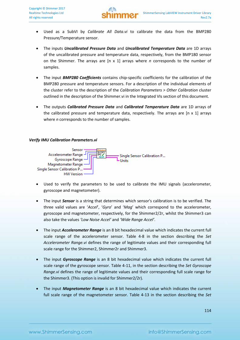
Copyright © Shimmer 2017
Realtime Technologies Ltd ShimmerSensing LabVIEW Instrument Driver Library
All rights reserved Rev2.7a
114
Used as a SubVI by Calibrate All Data.vi to calibrate the data from the BMP280
Pressure/Temperature sensor.
The inputs Uncalibrated Pressure Data and Uncalibrated Temperature Data are 1D arrays
of the uncalibrated pressure and temperature data, respectively, from the BMP180 sensor
on the Shimmer. The arrays are [n x 1] arrays where n corresponds to the number of
samples.
The input BMP280 Coefficients contains chip-specific coefficients for the calibration of the
BMP280 pressure and temperature sensors. For a description of the individual elements of
the cluster refer to the description of the Calibration Parameters > Other Calibration cluster
outlined in the description of the Shimmer.vi in the Integrated VIs section of this document.
The outputs Calibrated Pressure Data and Calibrated Temperature Data are 1D arrays of
the calibrated pressure and temperature data, respectively. The arrays are [n x 1] arrays
where n corresponds to the number of samples.
Verify IMU Calibration Parameters.vi
Used to verify the parameters to be used to calibrate the IMU signals (accelerometer,
gyroscope and magnetometer).
The input Sensor is a string that determines which sensor's calibration is to be verified. The
three valid values are ‘Accel’, ‘Gyro’ and ‘Mag’ which correspond to the accelerometer,
gyroscope and magnetometer, respectively, for the Shimmer2/2r, whilst the Shimmer3 can
also take the values ‘Low Noise Accel’ and ‘Wide Range Accel’.
The input Accelerometer Range is an 8 bit hexadecimal value which indicates the current full
scale range of the accelerometer sensor. Table 4-8 in the section describing the Set
Accelerometer Range.vi defines the range of legitimate values and their corresponding full
scale range for the Shimmer2, Shimmer2r and Shimmer3.
The input Gyroscope Range is an 8 bit hexadecimal value which indicates the current full
scale range of the gyroscope sensor. Table 4-11, in the section describing the Set Gyroscope
Range.vi defines the range of legitimate values and their corresponding full scale range for
the Shimmer3. (This option is invalid for Shimmer2/2r).
The input Magnetometer Range is an 8 bit hexadecimal value which indicates the current
full scale range of the magnetometer sensor. Table 4-13 in the section describing the Set
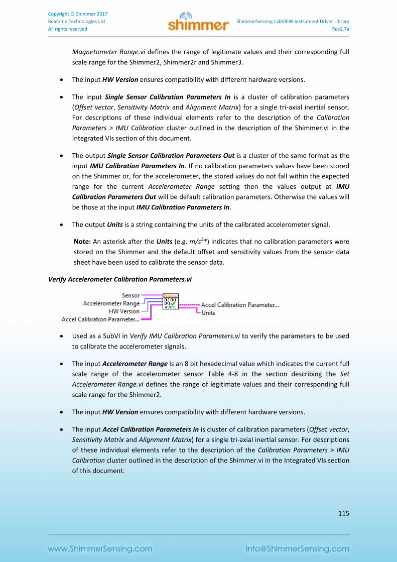
Copyright © Shimmer 2017
Realtime Technologies Ltd ShimmerSensing LabVIEW Instrument Driver Library
All rights reserved Rev2.7a
115
Magnetometer Range.vi defines the range of legitimate values and their corresponding full
scale range for the Shimmer2, Shimmer2r and Shimmer3.
The input HW Version ensures compatibility with different hardware versions.
The input Single Sensor Calibration Parameters In is a cluster of calibration parameters
(Offset vector, Sensitivity Matrix and Alignment Matrix) for a single tri-axial inertial sensor.
For descriptions of these individual elements refer to the description of the Calibration
Parameters > IMU Calibration cluster outlined in the description of the Shimmer.vi in the
Integrated VIs section of this document.
The output Single Sensor Calibration Parameters Out is a cluster of the same format as the
input IMU Calibration Parameters In. If no calibration parameters values have been stored
on the Shimmer or, for the accelerometer, the stored values do not fall within the expected
range for the current Accelerometer Range setting then the values output at IMU
Calibration Parameters Out will be default calibration parameters. Otherwise the values will
be those at the input IMU Calibration Parameters In.
The output Units is a string containing the units of the calibrated accelerometer signal.
Note: An asterisk after the Units (e.g. m/s2*) indicates that no calibration parameters were
stored on the Shimmer and the default offset and sensitivity values from the sensor data
sheet have been used to calibrate the sensor data.
Verify Accelerometer Calibration Parameters.vi
Used as a SubVI in Verify IMU Calibration Parameters.vi to verify the parameters to be used
to calibrate the accelerometer signals.
The input Accelerometer Range is an 8 bit hexadecimal value which indicates the current full
scale range of the accelerometer sensor Table 4-8 in the section describing the Set
Accelerometer Range.vi defines the range of legitimate values and their corresponding full
scale range for the Shimmer2.
The input HW Version ensures compatibility with different hardware versions.
The input Accel Calibration Parameters In is cluster of calibration parameters (Offset vector,
Sensitivity Matrix and Alignment Matrix) for a single tri-axial inertial sensor. For descriptions
of these individual elements refer to the description of the Calibration Parameters > IMU
Calibration cluster outlined in the description of the Shimmer.vi in the Integrated VIs section
of this document.
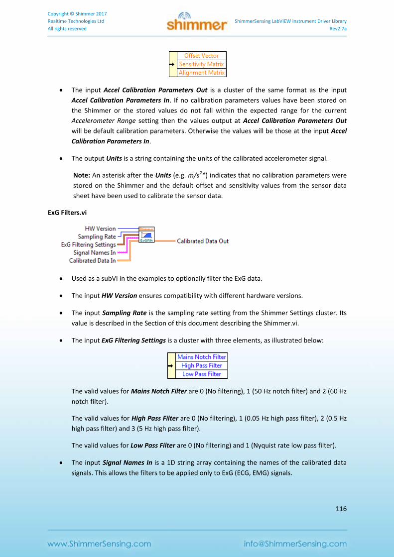
Copyright © Shimmer 2017
Realtime Technologies Ltd ShimmerSensing LabVIEW Instrument Driver Library
All rights reserved Rev2.7a
116
The input Accel Calibration Parameters Out is a cluster of the same format as the input
Accel Calibration Parameters In. If no calibration parameters values have been stored on
the Shimmer or the stored values do not fall within the expected range for the current
Accelerometer Range setting then the values output at Accel Calibration Parameters Out
will be default calibration parameters. Otherwise the values will be those at the input Accel
Calibration Parameters In.
The output Units is a string containing the units of the calibrated accelerometer signal.
Note: An asterisk after the Units (e.g. m/s2*) indicates that no calibration parameters were
stored on the Shimmer and the default offset and sensitivity values from the sensor data
sheet have been used to calibrate the sensor data.
ExG Filters.vi
Used as a subVI in the examples to optionally filter the ExG data.
The input HW Version ensures compatibility with different hardware versions.
The input Sampling Rate is the sampling rate setting from the Shimmer Settings cluster. Its
value is described in the Section of this document describing the Shimmer.vi.
The input ExG Filtering Settings is a cluster with three elements, as illustrated below:
The valid values for Mains Notch Filter are 0 (No filtering), 1 (50 Hz notch filter) and 2 (60 Hz
notch filter).
The valid values for High Pass Filter are 0 (No filtering), 1 (0.05 Hz high pass filter), 2 (0.5 Hz
high pass filter) and 3 (5 Hz high pass filter).
The valid values for Low Pass Filter are 0 (No filtering) and 1 (Nyquist rate low pass filter).
The input Signal Names In is a 1D string array containing the names of the calibrated data
signals. This allows the filters to be applied only to ExG (ECG, EMG) signals.
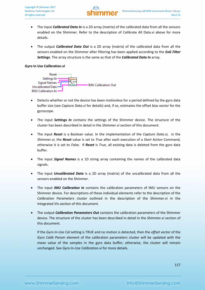
Copyright © Shimmer 2017
Realtime Technologies Ltd ShimmerSensing LabVIEW Instrument Driver Library
All rights reserved Rev2.7a
117
The input Calibrated Data In is a 2D array (matrix) of the calibrated data from all the sensors
enabled on the Shimmer. Refer to the description of Calibrate All Data.vi above for more
details.
The output Calibrated Data Out is a 2D array (matrix) of the calibrated data from all the
sensors enabled on the Shimmer after filtering has been applied according to the ExG Filter
Settings. The array structure is the same as that of the Calibrated Data In array.
Gyro In Use Calibration.vi
Detects whether or not the device has been motionless for a period defined by the gyro data
buffer size (see Capture Data.vi for details) and, if so, estimates the offset bias vector for the
gyroscope.
The input Settings In contains the settings of the Shimmer device. The structure of the
cluster has been described in detail in the Shimmer.vi section of this document.
The input Reset is a Boolean value. In the implementation of the Capture Data.vi, in the
Shimmer.vi, the Reset value is set to True after each execution of a Start Action Command,
otherwise it is set to False. If Reset is True, all existing data is deleted from the gyro data
buffer.
The input Signal Names is a 1D string array containing the names of the calibrated data
signals.
The input Uncalibrated Data is a 2D array (matrix) of the uncalibrated data from all the
sensors enabled on the Shimmer.
The input IMU Calibration In contains the calibration parameters of IMU sensors on the
Shimmer device. For descriptions of these individual elements refer to the description of the
Calibration Parameters cluster outlined in the description of the Shimmer.vi in the
Integrated VIs section of this document.
The output Calibration Parameters Out contains the calibration parameters of the Shimmer
device. The structure of the cluster has been described in detail in the Shimmer.vi section of
this document.
If the Gyro In-Use Cal setting is TRUE and no motion is detected, then the offset vector of the
Gyro Calib Param element of the calibration parameters cluster will be updated with the
mean value of the samples in the gyro data buffer; otherwise, the cluster will remain
unchanged. See Gyro In-Use Calibration.vi for more details.
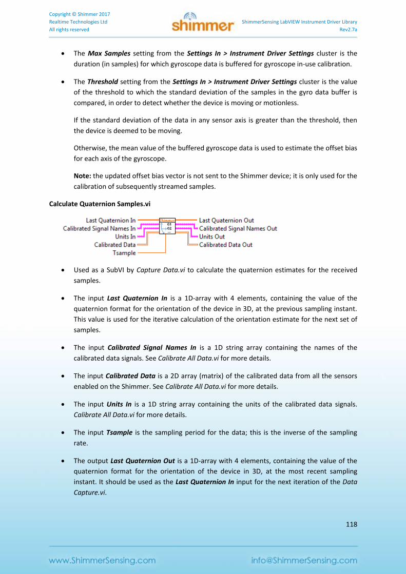
Copyright © Shimmer 2017
Realtime Technologies Ltd ShimmerSensing LabVIEW Instrument Driver Library
All rights reserved Rev2.7a
118
The Max Samples setting from the Settings In > Instrument Driver Settings cluster is the
duration (in samples) for which gyroscope data is buffered for gyroscope in-use calibration.
The Threshold setting from the Settings In > Instrument Driver Settings cluster is the value
of the threshold to which the standard deviation of the samples in the gyro data buffer is
compared, in order to detect whether the device is moving or motionless.
If the standard deviation of the data in any sensor axis is greater than the threshold, then
the device is deemed to be moving.
Otherwise, the mean value of the buffered gyroscope data is used to estimate the offset bias
for each axis of the gyroscope.
Note: the updated offset bias vector is not sent to the Shimmer device; it is only used for the
calibration of subsequently streamed samples.
Calculate Quaternion Samples.vi
Used as a SubVI by Capture Data.vi to calculate the quaternion estimates for the received
samples.
The input Last Quaternion In is a 1D-array with 4 elements, containing the value of the
quaternion format for the orientation of the device in 3D, at the previous sampling instant.
This value is used for the iterative calculation of the orientation estimate for the next set of
samples.
The input Calibrated Signal Names In is a 1D string array containing the names of the
calibrated data signals. See Calibrate All Data.vi for more details.
The input Calibrated Data is a 2D array (matrix) of the calibrated data from all the sensors
enabled on the Shimmer. See Calibrate All Data.vi for more details.
The input Units In is a 1D string array containing the units of the calibrated data signals.
Calibrate All Data.vi for more details.
The input Tsample is the sampling period for the data; this is the inverse of the sampling
rate.
The output Last Quaternion Out is a 1D-array with 4 elements, containing the value of the
quaternion format for the orientation of the device in 3D, at the most recent sampling
instant. It should be used as the Last Quaternion In input for the next iteration of the Data
Capture.vi.
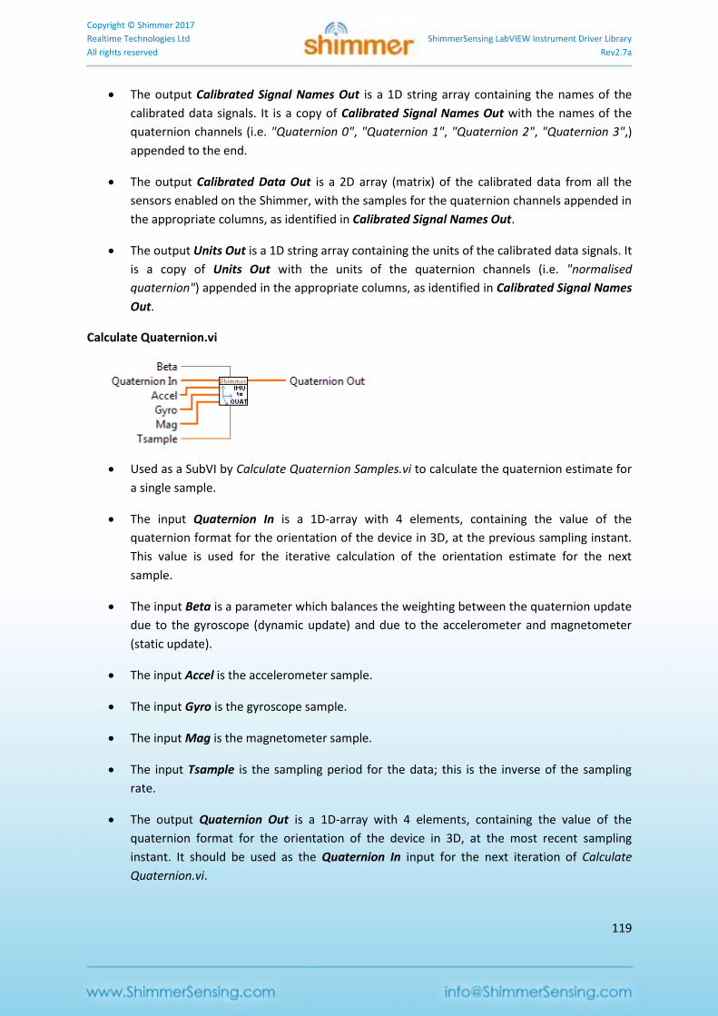
Copyright © Shimmer 2017
Realtime Technologies Ltd ShimmerSensing LabVIEW Instrument Driver Library
All rights reserved Rev2.7a
119
The output Calibrated Signal Names Out is a 1D string array containing the names of the
calibrated data signals. It is a copy of Calibrated Signal Names Out with the names of the
quaternion channels (i.e. "Quaternion 0", "Quaternion 1", "Quaternion 2", "Quaternion 3",)
appended to the end.
The output Calibrated Data Out is a 2D array (matrix) of the calibrated data from all the
sensors enabled on the Shimmer, with the samples for the quaternion channels appended in
the appropriate columns, as identified in Calibrated Signal Names Out.
The output Units Out is a 1D string array containing the units of the calibrated data signals. It
is a copy of Units Out with the units of the quaternion channels (i.e. "normalised
quaternion") appended in the appropriate columns, as identified in Calibrated Signal Names
Out.
Calculate Quaternion.vi
Used as a SubVI by Calculate Quaternion Samples.vi to calculate the quaternion estimate for
a single sample.
The input Quaternion In is a 1D-array with 4 elements, containing the value of the
quaternion format for the orientation of the device in 3D, at the previous sampling instant.
This value is used for the iterative calculation of the orientation estimate for the next
sample.
The input Beta is a parameter which balances the weighting between the quaternion update
due to the gyroscope (dynamic update) and due to the accelerometer and magnetometer
(static update).
The input Accel is the accelerometer sample.
The input Gyro is the gyroscope sample.
The input Mag is the magnetometer sample.
The input Tsample is the sampling period for the data; this is the inverse of the sampling
rate.
The output Quaternion Out is a 1D-array with 4 elements, containing the value of the
quaternion format for the orientation of the device in 3D, at the most recent sampling
instant. It should be used as the Quaternion In input for the next iteration of Calculate
Quaternion.vi.
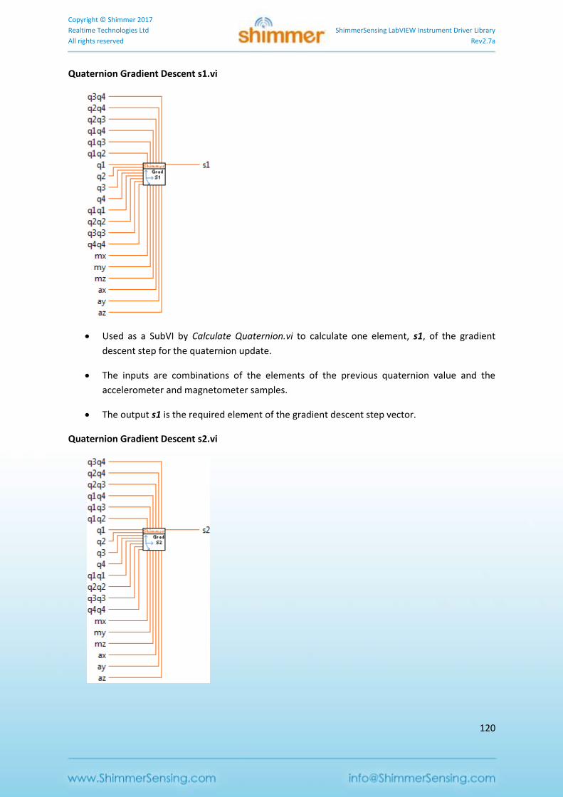
Copyright © Shimmer 2017
Realtime Technologies Ltd ShimmerSensing LabVIEW Instrument Driver Library
All rights reserved Rev2.7a
120
Quaternion Gradient Descent s1.vi
Used as a SubVI by Calculate Quaternion.vi to calculate one element, s1, of the gradient
descent step for the quaternion update.
The inputs are combinations of the elements of the previous quaternion value and the
accelerometer and magnetometer samples.
The output s1 is the required element of the gradient descent step vector.
Quaternion Gradient Descent s2.vi
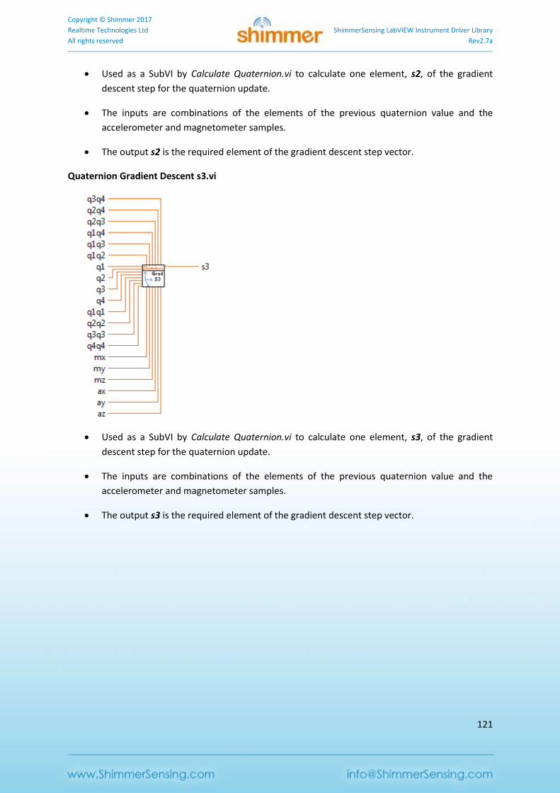
Copyright © Shimmer 2017
Realtime Technologies Ltd ShimmerSensing LabVIEW Instrument Driver Library
All rights reserved Rev2.7a
121
Used as a SubVI by Calculate Quaternion.vi to calculate one element, s2, of the gradient
descent step for the quaternion update.
The inputs are combinations of the elements of the previous quaternion value and the
accelerometer and magnetometer samples.
The output s2 is the required element of the gradient descent step vector.
Quaternion Gradient Descent s3.vi
Used as a SubVI by Calculate Quaternion.vi to calculate one element, s3, of the gradient
descent step for the quaternion update.
The inputs are combinations of the elements of the previous quaternion value and the
accelerometer and magnetometer samples.
The output s3 is the required element of the gradient descent step vector.
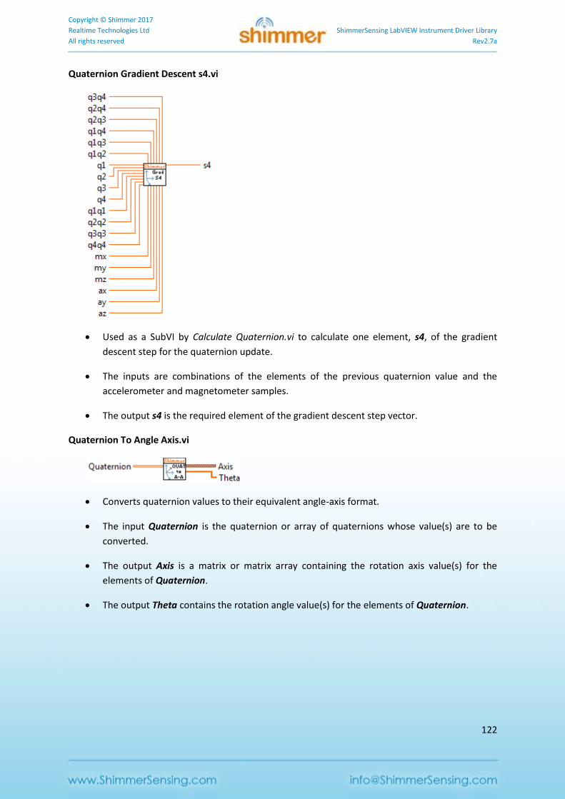
Copyright © Shimmer 2017
Realtime Technologies Ltd ShimmerSensing LabVIEW Instrument Driver Library
All rights reserved Rev2.7a
122
Quaternion Gradient Descent s4.vi
Used as a SubVI by Calculate Quaternion.vi to calculate one element, s4, of the gradient
descent step for the quaternion update.
The inputs are combinations of the elements of the previous quaternion value and the
accelerometer and magnetometer samples.
The output s4 is the required element of the gradient descent step vector.
Quaternion To Angle Axis.vi
Converts quaternion values to their equivalent angle-axis format.
The input Quaternion is the quaternion or array of quaternions whose value(s) are to be
converted.
The output Axis is a matrix or matrix array containing the rotation axis value(s) for the
elements of Quaternion.
The output Theta contains the rotation angle value(s) for the elements of Quaternion.
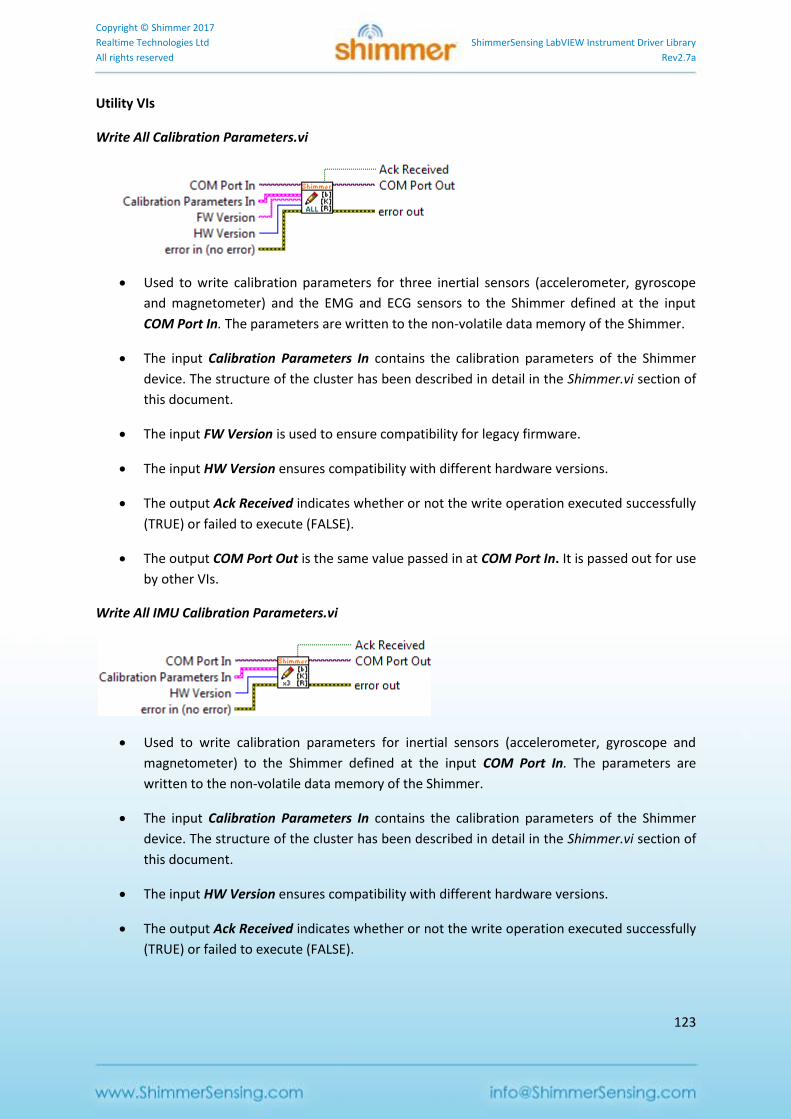
Copyright © Shimmer 2017
Realtime Technologies Ltd ShimmerSensing LabVIEW Instrument Driver Library
All rights reserved Rev2.7a
123
Utility VIs
Write All Calibration Parameters.vi
Used to write calibration parameters for three inertial sensors (accelerometer, gyroscope
and magnetometer) and the EMG and ECG sensors to the Shimmer defined at the input
COM Port In. The parameters are written to the non-volatile data memory of the Shimmer.
The input Calibration Parameters In contains the calibration parameters of the Shimmer
device. The structure of the cluster has been described in detail in the Shimmer.vi section of
this document.
The input FW Version is used to ensure compatibility for legacy firmware.
The input HW Version ensures compatibility with different hardware versions.
The output Ack Received indicates whether or not the write operation executed successfully
(TRUE) or failed to execute (FALSE).
The output COM Port Out is the same value passed in at COM Port In. It is passed out for use
by other VIs.
Write All IMU Calibration Parameters.vi
Used to write calibration parameters for inertial sensors (accelerometer, gyroscope and
magnetometer) to the Shimmer defined at the input COM Port In. The parameters are
written to the non-volatile data memory of the Shimmer.
The input Calibration Parameters In contains the calibration parameters of the Shimmer
device. The structure of the cluster has been described in detail in the Shimmer.vi section of
this document.
The input HW Version ensures compatibility with different hardware versions.
The output Ack Received indicates whether or not the write operation executed successfully
(TRUE) or failed to execute (FALSE).
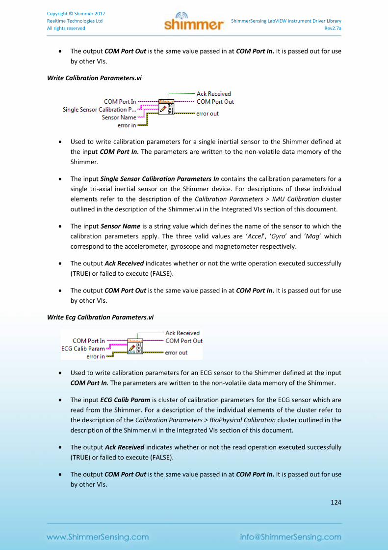
Copyright © Shimmer 2017
Realtime Technologies Ltd ShimmerSensing LabVIEW Instrument Driver Library
All rights reserved Rev2.7a
124
The output COM Port Out is the same value passed in at COM Port In. It is passed out for use
by other VIs.
Write Calibration Parameters.vi
Used to write calibration parameters for a single inertial sensor to the Shimmer defined at
the input COM Port In. The parameters are written to the non-volatile data memory of the
Shimmer.
The input Single Sensor Calibration Parameters In contains the calibration parameters for a
single tri-axial inertial sensor on the Shimmer device. For descriptions of these individual
elements refer to the description of the Calibration Parameters > IMU Calibration cluster
outlined in the description of the Shimmer.vi in the Integrated VIs section of this document.
The input Sensor Name is a string value which defines the name of the sensor to which the
calibration parameters apply. The three valid values are ‘Accel’, ‘Gyro’ and ‘Mag’ which
correspond to the accelerometer, gyroscope and magnetometer respectively.
The output Ack Received indicates whether or not the write operation executed successfully
(TRUE) or failed to execute (FALSE).
The output COM Port Out is the same value passed in at COM Port In. It is passed out for use
by other VIs.
Write Ecg Calibration Parameters.vi
Used to write calibration parameters for an ECG sensor to the Shimmer defined at the input
COM Port In. The parameters are written to the non-volatile data memory of the Shimmer.
The input ECG Calib Param is cluster of calibration parameters for the ECG sensor which are
read from the Shimmer. For a description of the individual elements of the cluster refer to
the description of the Calibration Parameters > BioPhysical Calibration cluster outlined in the
description of the Shimmer.vi in the Integrated VIs section of this document.
The output Ack Received indicates whether or not the read operation executed successfully
(TRUE) or failed to execute (FALSE).
The output COM Port Out is the same value passed in at COM Port In. It is passed out for use
by other VIs.
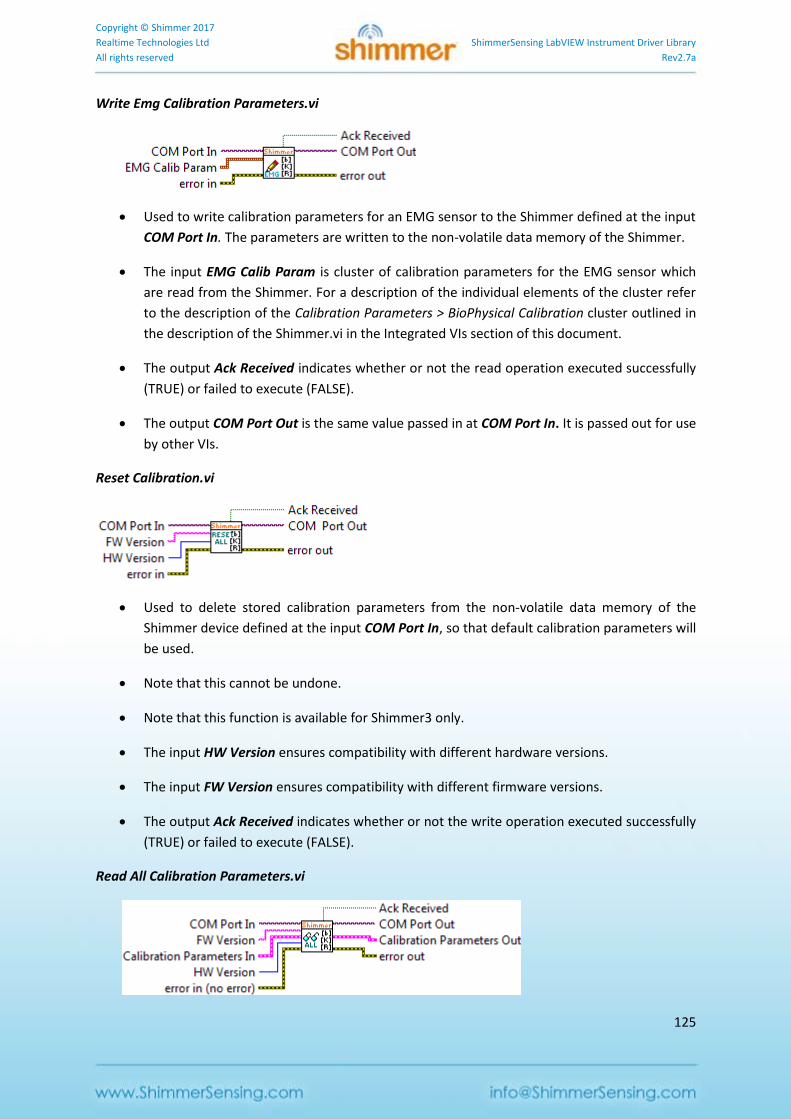
Copyright © Shimmer 2017
Realtime Technologies Ltd ShimmerSensing LabVIEW Instrument Driver Library
All rights reserved Rev2.7a
125
Write Emg Calibration Parameters.vi
Used to write calibration parameters for an EMG sensor to the Shimmer defined at the input
COM Port In. The parameters are written to the non-volatile data memory of the Shimmer.
The input EMG Calib Param is cluster of calibration parameters for the EMG sensor which
are read from the Shimmer. For a description of the individual elements of the cluster refer
to the description of the Calibration Parameters > BioPhysical Calibration cluster outlined in
the description of the Shimmer.vi in the Integrated VIs section of this document.
The output Ack Received indicates whether or not the read operation executed successfully
(TRUE) or failed to execute (FALSE).
The output COM Port Out is the same value passed in at COM Port In. It is passed out for use
by other VIs.
Reset Calibration.vi
Used to delete stored calibration parameters from the non-volatile data memory of the
Shimmer device defined at the input COM Port In, so that default calibration parameters will
be used.
Note that this cannot be undone.
Note that this function is available for Shimmer3 only.
The input HW Version ensures compatibility with different hardware versions.
The input FW Version ensures compatibility with different firmware versions.
The output Ack Received indicates whether or not the write operation executed successfully
(TRUE) or failed to execute (FALSE).
Read All Calibration Parameters.vi
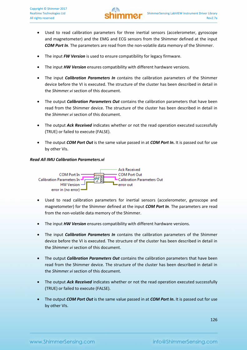
Copyright © Shimmer 2017
Realtime Technologies Ltd ShimmerSensing LabVIEW Instrument Driver Library
All rights reserved Rev2.7a
126
Used to read calibration parameters for three inertial sensors (accelerometer, gyroscope
and magnetometer) and the EMG and ECG sensors from the Shimmer defined at the input
COM Port In. The parameters are read from the non-volatile data memory of the Shimmer.
The input FW Version is used to ensure compatibility for legacy firmware.
The input HW Version ensures compatibility with different hardware versions.
The input Calibration Parameters In contains the calibration parameters of the Shimmer
device before the VI is executed. The structure of the cluster has been described in detail in
the Shimmer.vi section of this document.
The output Calibration Parameters Out contains the calibration parameters that have been
read from the Shimmer device. The structure of the cluster has been described in detail in
the Shimmer.vi section of this document.
The output Ack Received indicates whether or not the read operation executed successfully
(TRUE) or failed to execute (FALSE).
The output COM Port Out is the same value passed in at COM Port In. It is passed out for use
by other VIs.
Read All IMU Calibration Parameters.vi
Used to read calibration parameters for inertial sensors (accelerometer, gyroscope and
magnetometer) for the Shimmer defined at the input COM Port In. The parameters are read
from the non-volatile data memory of the Shimmer.
The input HW Version ensures compatibility with different hardware versions.
The input Calibration Parameters In contains the calibration parameters of the Shimmer
device before the VI is executed. The structure of the cluster has been described in detail in
the Shimmer.vi section of this document.
The output Calibration Parameters Out contains the calibration parameters that have been
read from the Shimmer device. The structure of the cluster has been described in detail in
the Shimmer.vi section of this document.
The output Ack Received indicates whether or not the read operation executed successfully
(TRUE) or failed to execute (FALSE).
The output COM Port Out is the same value passed in at COM Port In. It is passed out for use
by other VIs.
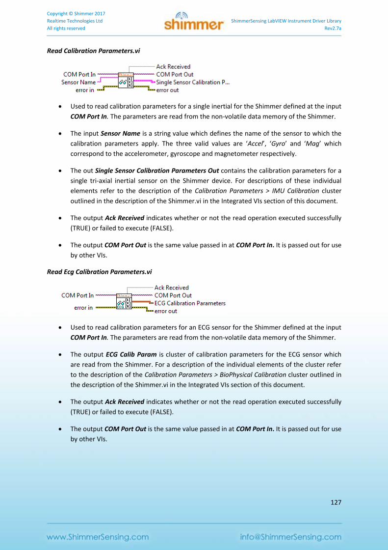
Copyright © Shimmer 2017
Realtime Technologies Ltd ShimmerSensing LabVIEW Instrument Driver Library
All rights reserved Rev2.7a
127
Read Calibration Parameters.vi
Used to read calibration parameters for a single inertial for the Shimmer defined at the input
COM Port In. The parameters are read from the non-volatile data memory of the Shimmer.
The input Sensor Name is a string value which defines the name of the sensor to which the
calibration parameters apply. The three valid values are ‘Accel’, ‘Gyro’ and ‘Mag’ which
correspond to the accelerometer, gyroscope and magnetometer respectively.
The out Single Sensor Calibration Parameters Out contains the calibration parameters for a
single tri-axial inertial sensor on the Shimmer device. For descriptions of these individual
elements refer to the description of the Calibration Parameters > IMU Calibration cluster
outlined in the description of the Shimmer.vi in the Integrated VIs section of this document.
The output Ack Received indicates whether or not the read operation executed successfully
(TRUE) or failed to execute (FALSE).
The output COM Port Out is the same value passed in at COM Port In. It is passed out for use
by other VIs.
Read Ecg Calibration Parameters.vi
Used to read calibration parameters for an ECG sensor for the Shimmer defined at the input
COM Port In. The parameters are read from the non-volatile data memory of the Shimmer.
The output ECG Calib Param is cluster of calibration parameters for the ECG sensor which
are read from the Shimmer. For a description of the individual elements of the cluster refer
to the description of the Calibration Parameters > BioPhysical Calibration cluster outlined in
the description of the Shimmer.vi in the Integrated VIs section of this document.
The output Ack Received indicates whether or not the read operation executed successfully
(TRUE) or failed to execute (FALSE).
The output COM Port Out is the same value passed in at COM Port In. It is passed out for use
by other VIs.
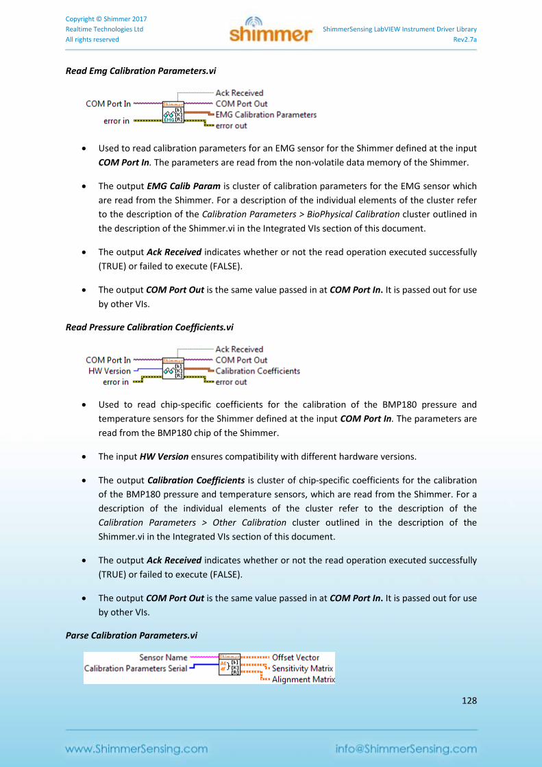
Copyright © Shimmer 2017
Realtime Technologies Ltd ShimmerSensing LabVIEW Instrument Driver Library
All rights reserved Rev2.7a
128
Read Emg Calibration Parameters.vi
Used to read calibration parameters for an EMG sensor for the Shimmer defined at the input
COM Port In. The parameters are read from the non-volatile data memory of the Shimmer.
The output EMG Calib Param is cluster of calibration parameters for the EMG sensor which
are read from the Shimmer. For a description of the individual elements of the cluster refer
to the description of the Calibration Parameters > BioPhysical Calibration cluster outlined in
the description of the Shimmer.vi in the Integrated VIs section of this document.
The output Ack Received indicates whether or not the read operation executed successfully
(TRUE) or failed to execute (FALSE).
The output COM Port Out is the same value passed in at COM Port In. It is passed out for use
by other VIs.
Read Pressure Calibration Coefficients.vi
Used to read chip-specific coefficients for the calibration of the BMP180 pressure and
temperature sensors for the Shimmer defined at the input COM Port In. The parameters are
read from the BMP180 chip of the Shimmer.
The input HW Version ensures compatibility with different hardware versions.
The output Calibration Coefficients is cluster of chip-specific coefficients for the calibration
of the BMP180 pressure and temperature sensors, which are read from the Shimmer. For a
description of the individual elements of the cluster refer to the description of the
Calibration Parameters > Other Calibration cluster outlined in the description of the
Shimmer.vi in the Integrated VIs section of this document.
The output Ack Received indicates whether or not the read operation executed successfully
(TRUE) or failed to execute (FALSE).
The output COM Port Out is the same value passed in at COM Port In. It is passed out for use
by other VIs.
Parse Calibration Parameters.vi
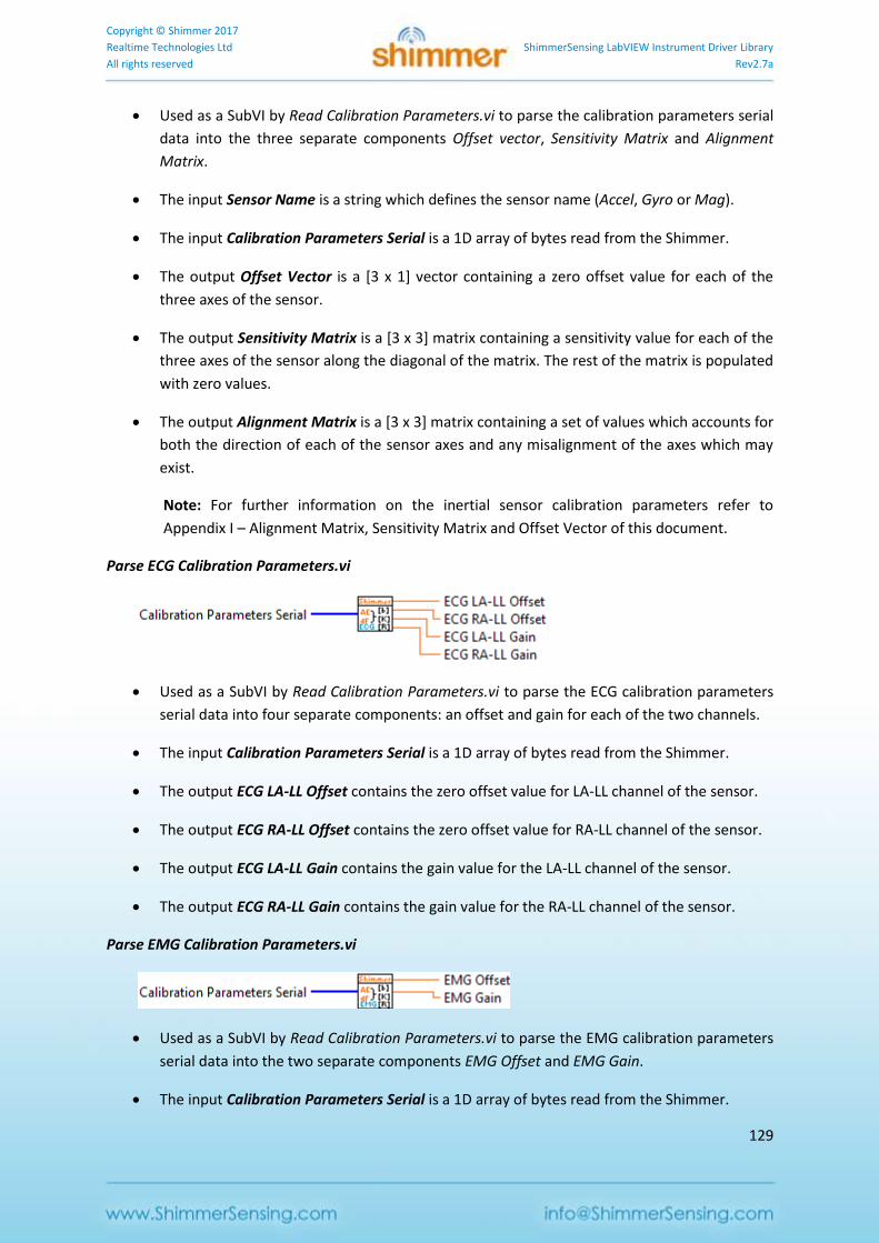
Copyright © Shimmer 2017
Realtime Technologies Ltd ShimmerSensing LabVIEW Instrument Driver Library
All rights reserved Rev2.7a
129
Used as a SubVI by Read Calibration Parameters.vi to parse the calibration parameters serial
data into the three separate components Offset vector, Sensitivity Matrix and Alignment
Matrix.
The input Sensor Name is a string which defines the sensor name (Accel, Gyro or Mag).
The input Calibration Parameters Serial is a 1D array of bytes read from the Shimmer.
The output Offset Vector is a [3 x 1] vector containing a zero offset value for each of the
three axes of the sensor.
The output Sensitivity Matrix is a [3 x 3] matrix containing a sensitivity value for each of the
three axes of the sensor along the diagonal of the matrix. The rest of the matrix is populated
with zero values.
The output Alignment Matrix is a [3 x 3] matrix containing a set of values which accounts for
both the direction of each of the sensor axes and any misalignment of the axes which may
exist.
Note: For further information on the inertial sensor calibration parameters refer to
Appendix I – Alignment Matrix, Sensitivity Matrix and Offset Vector of this document.
Parse ECG Calibration Parameters.vi
Used as a SubVI by Read Calibration Parameters.vi to parse the ECG calibration parameters
serial data into four separate components: an offset and gain for each of the two channels.
The input Calibration Parameters Serial is a 1D array of bytes read from the Shimmer.
The output ECG LA-LL Offset contains the zero offset value for LA-LL channel of the sensor.
The output ECG RA-LL Offset contains the zero offset value for RA-LL channel of the sensor.
The output ECG LA-LL Gain contains the gain value for the LA-LL channel of the sensor.
The output ECG RA-LL Gain contains the gain value for the RA-LL channel of the sensor.
Parse EMG Calibration Parameters.vi
Used as a SubVI by Read Calibration Parameters.vi to parse the EMG calibration parameters
serial data into the two separate components EMG Offset and EMG Gain.
The input Calibration Parameters Serial is a 1D array of bytes read from the Shimmer.
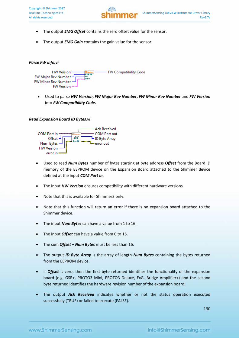
Copyright © Shimmer 2017
Realtime Technologies Ltd ShimmerSensing LabVIEW Instrument Driver Library
All rights reserved Rev2.7a
130
The output EMG Offset contains the zero offset value for the sensor.
The output EMG Gain contains the gain value for the sensor.
Parse FW info.vi
Used to parse HW Version, FW Major Rev Number, FW Minor Rev Number and FW Version
into FW Compatibility Code.
Read Expansion Board ID Bytes.vi
Used to read Num Bytes number of bytes starting at byte address Offset from the Board ID
memory of the EEPROM device on the Expansion Board attached to the Shimmer device
defined at the input COM Port In.
The input HW Version ensures compatibility with different hardware versions.
Note that this is available for Shimmer3 only.
Note that this function will return an error if there is no expansion board attached to the
Shimmer device.
The input Num Bytes can have a value from 1 to 16.
The input Offset can have a value from 0 to 15.
The sum Offset + Num Bytes must be less than 16.
The output ID Byte Array is the array of length Num Bytes containing the bytes returned
from the EEPROM device.
If Offset is zero, then the first byte returned identifies the functionality of the expansion
board (e.g. GSR+, PROTO3 Mini, PROTO3 Deluxe, ExG, Bridge Amplifier+) and the second
byte returned identifies the hardware revision number of the expansion board.
The output Ack Received indicates whether or not the status operation executed
successfully (TRUE) or failed to execute (FALSE).
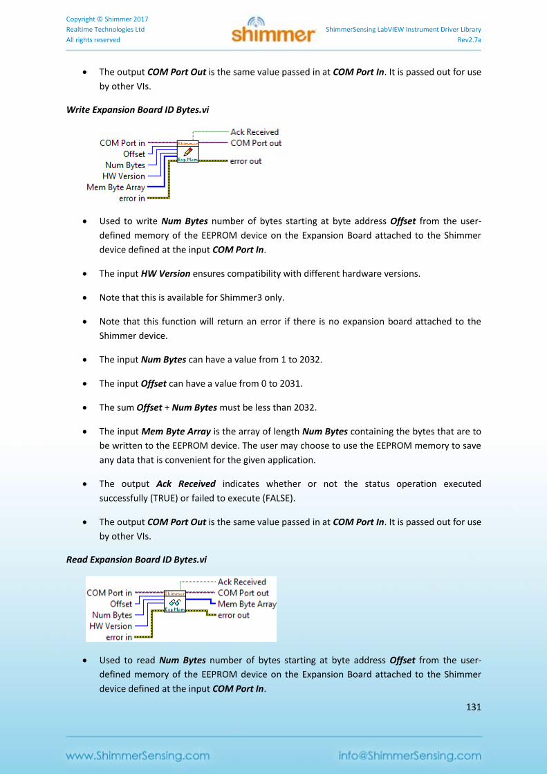
Copyright © Shimmer 2017
Realtime Technologies Ltd ShimmerSensing LabVIEW Instrument Driver Library
All rights reserved Rev2.7a
131
The output COM Port Out is the same value passed in at COM Port In. It is passed out for use
by other VIs.
Write Expansion Board ID Bytes.vi
Used to write Num Bytes number of bytes starting at byte address Offset from the user-
defined memory of the EEPROM device on the Expansion Board attached to the Shimmer
device defined at the input COM Port In.
The input HW Version ensures compatibility with different hardware versions.
Note that this is available for Shimmer3 only.
Note that this function will return an error if there is no expansion board attached to the
Shimmer device.
The input Num Bytes can have a value from 1 to 2032.
The input Offset can have a value from 0 to 2031.
The sum Offset + Num Bytes must be less than 2032.
The input Mem Byte Array is the array of length Num Bytes containing the bytes that are to
be written to the EEPROM device. The user may choose to use the EEPROM memory to save
any data that is convenient for the given application.
The output Ack Received indicates whether or not the status operation executed
successfully (TRUE) or failed to execute (FALSE).
The output COM Port Out is the same value passed in at COM Port In. It is passed out for use
by other VIs.
Read Expansion Board ID Bytes.vi
Used to read Num Bytes number of bytes starting at byte address Offset from the user-
defined memory of the EEPROM device on the Expansion Board attached to the Shimmer
device defined at the input COM Port In.
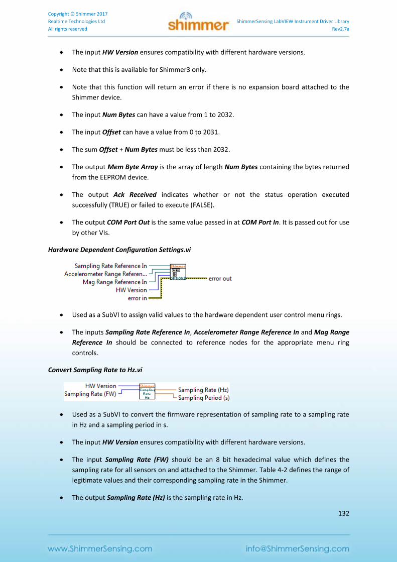
Copyright © Shimmer 2017
Realtime Technologies Ltd ShimmerSensing LabVIEW Instrument Driver Library
All rights reserved Rev2.7a
132
The input HW Version ensures compatibility with different hardware versions.
Note that this is available for Shimmer3 only.
Note that this function will return an error if there is no expansion board attached to the
Shimmer device.
The input Num Bytes can have a value from 1 to 2032.
The input Offset can have a value from 0 to 2031.
The sum Offset + Num Bytes must be less than 2032.
The output Mem Byte Array is the array of length Num Bytes containing the bytes returned
from the EEPROM device.
The output Ack Received indicates whether or not the status operation executed
successfully (TRUE) or failed to execute (FALSE).
The output COM Port Out is the same value passed in at COM Port In. It is passed out for use
by other VIs.
Hardware Dependent Configuration Settings.vi
Used as a SubVI to assign valid values to the hardware dependent user control menu rings.
The inputs Sampling Rate Reference In, Accelerometer Range Reference In and Mag Range
Reference In should be connected to reference nodes for the appropriate menu ring
controls.
Convert Sampling Rate to Hz.vi
Used as a SubVI to convert the firmware representation of sampling rate to a sampling rate
in Hz and a sampling period in s.
The input HW Version ensures compatibility with different hardware versions.
The input Sampling Rate (FW) should be an 8 bit hexadecimal value which defines the
sampling rate for all sensors on and attached to the Shimmer. Table 4-2 defines the range of
legitimate values and their corresponding sampling rate in the Shimmer.
The output Sampling Rate (Hz) is the sampling rate in Hz.
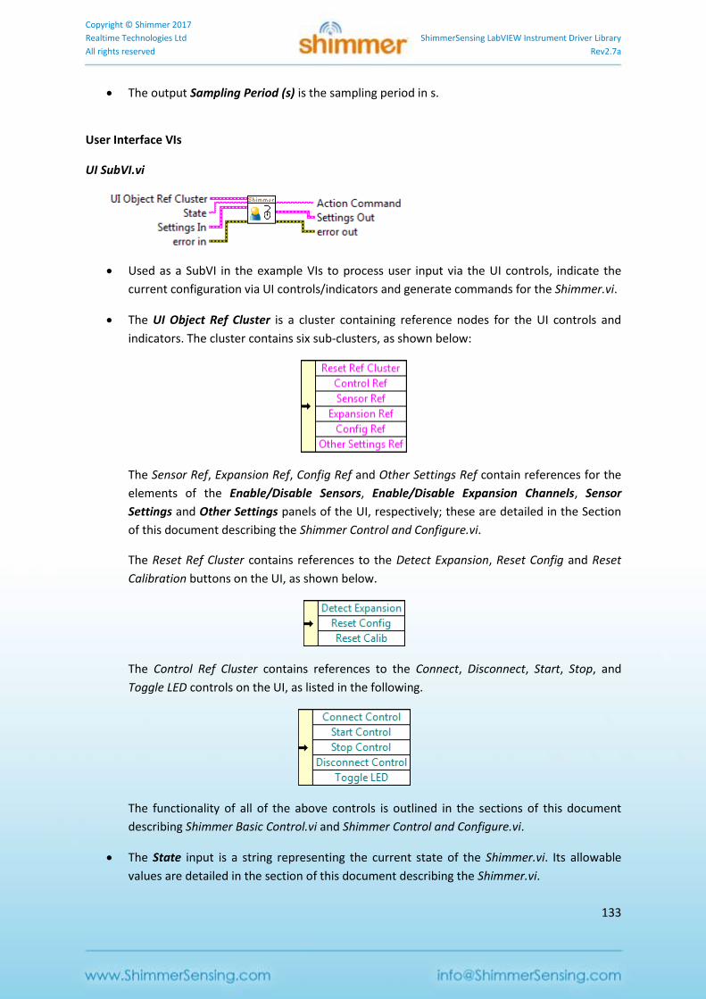
Copyright © Shimmer 2017
Realtime Technologies Ltd ShimmerSensing LabVIEW Instrument Driver Library
All rights reserved Rev2.7a
133
The output Sampling Period (s) is the sampling period in s.
User Interface VIs
UI SubVI.vi
Used as a SubVI in the example VIs to process user input via the UI controls, indicate the
current configuration via UI controls/indicators and generate commands for the Shimmer.vi.
The UI Object Ref Cluster is a cluster containing reference nodes for the UI controls and
indicators. The cluster contains six sub-clusters, as shown below:
The Sensor Ref, Expansion Ref, Config Ref and Other Settings Ref contain references for the
elements of the Enable/Disable Sensors, Enable/Disable Expansion Channels, Sensor
Settings and Other Settings panels of the UI, respectively; these are detailed in the Section
of this document describing the Shimmer Control and Configure.vi.
The Reset Ref Cluster contains references to the Detect Expansion, Reset Config and Reset
Calibration buttons on the UI, as shown below.
The Control Ref Cluster contains references to the Connect, Disconnect, Start, Stop, and
Toggle LED controls on the UI, as listed in the following.
The functionality of all of the above controls is outlined in the sections of this document
describing Shimmer Basic Control.vi and Shimmer Control and Configure.vi.
The State input is a string representing the current state of the Shimmer.vi. Its allowable
values are detailed in the section of this document describing the Shimmer.vi.
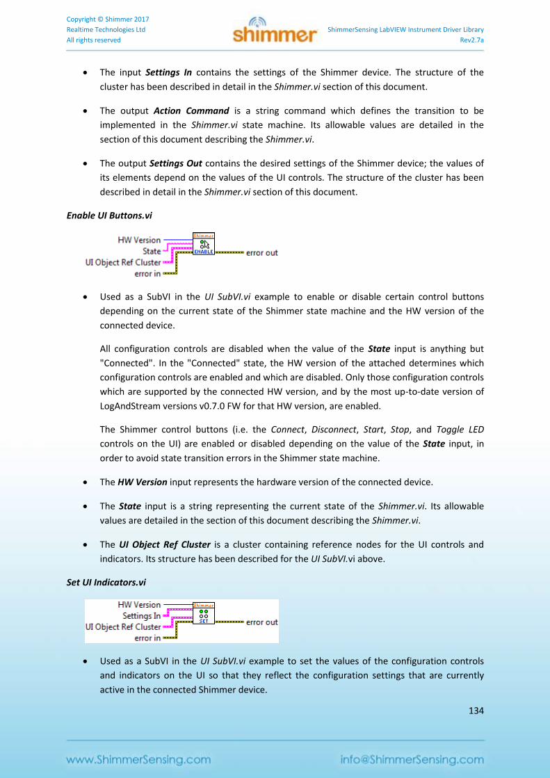
Copyright © Shimmer 2017
Realtime Technologies Ltd ShimmerSensing LabVIEW Instrument Driver Library
All rights reserved Rev2.7a
134
The input Settings In contains the settings of the Shimmer device. The structure of the
cluster has been described in detail in the Shimmer.vi section of this document.
The output Action Command is a string command which defines the transition to be
implemented in the Shimmer.vi state machine. Its allowable values are detailed in the
section of this document describing the Shimmer.vi.
The output Settings Out contains the desired settings of the Shimmer device; the values of
its elements depend on the values of the UI controls. The structure of the cluster has been
described in detail in the Shimmer.vi section of this document.
Enable UI Buttons.vi
Used as a SubVI in the UI SubVI.vi example to enable or disable certain control buttons
depending on the current state of the Shimmer state machine and the HW version of the
connected device.
All configuration controls are disabled when the value of the State input is anything but
"Connected". In the "Connected" state, the HW version of the attached determines which
configuration controls are enabled and which are disabled. Only those configuration controls
which are supported by the connected HW version, and by the most up-to-date version of
LogAndStream versions v0.7.0 FW for that HW version, are enabled.
The Shimmer control buttons (i.e. the Connect, Disconnect, Start, Stop, and Toggle LED
controls on the UI) are enabled or disabled depending on the value of the State input, in
order to avoid state transition errors in the Shimmer state machine.
The HW Version input represents the hardware version of the connected device.
The State input is a string representing the current state of the Shimmer.vi. Its allowable
values are detailed in the section of this document describing the Shimmer.vi.
The UI Object Ref Cluster is a cluster containing reference nodes for the UI controls and
indicators. Its structure has been described for the UI SubVI.vi above.
Set UI Indicators.vi
Used as a SubVI in the UI SubVI.vi example to set the values of the configuration controls
and indicators on the UI so that they reflect the configuration settings that are currently
active in the connected Shimmer device.
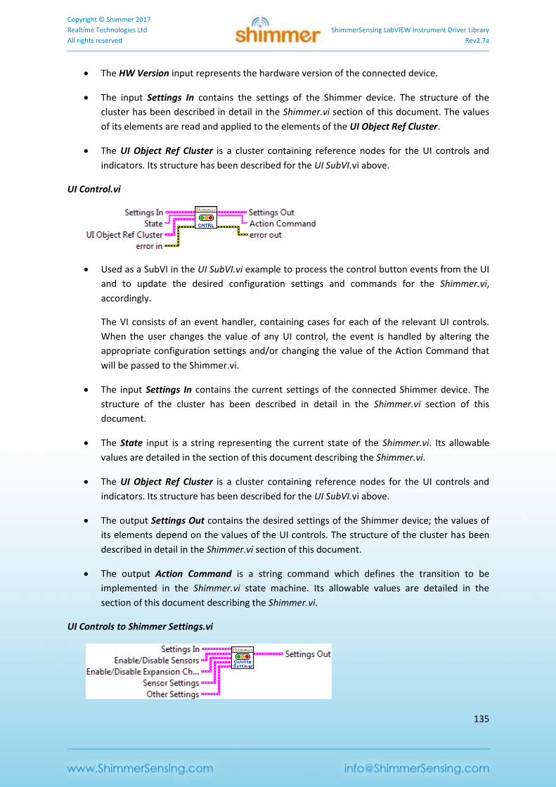
Copyright © Shimmer 2017
Realtime Technologies Ltd ShimmerSensing LabVIEW Instrument Driver Library
All rights reserved Rev2.7a
135
The HW Version input represents the hardware version of the connected device.
The input Settings In contains the settings of the Shimmer device. The structure of the
cluster has been described in detail in the Shimmer.vi section of this document. The values
of its elements are read and applied to the elements of the UI Object Ref Cluster.
The UI Object Ref Cluster is a cluster containing reference nodes for the UI controls and
indicators. Its structure has been described for the UI SubVI.vi above.
UI Control.vi
Used as a SubVI in the UI SubVI.vi example to process the control button events from the UI
and to update the desired configuration settings and commands for the Shimmer.vi,
accordingly.
The VI consists of an event handler, containing cases for each of the relevant UI controls.
When the user changes the value of any UI control, the event is handled by altering the
appropriate configuration settings and/or changing the value of the Action Command that
will be passed to the Shimmer.vi.
The input Settings In contains the current settings of the connected Shimmer device. The
structure of the cluster has been described in detail in the Shimmer.vi section of this
document.
The State input is a string representing the current state of the Shimmer.vi. Its allowable
values are detailed in the section of this document describing the Shimmer.vi.
The UI Object Ref Cluster is a cluster containing reference nodes for the UI controls and
indicators. Its structure has been described for the UI SubVI.vi above.
The output Settings Out contains the desired settings of the Shimmer device; the values of
its elements depend on the values of the UI controls. The structure of the cluster has been
described in detail in the Shimmer.vi section of this document.
The output Action Command is a string command which defines the transition to be
implemented in the Shimmer.vi state machine. Its allowable values are detailed in the
section of this document describing the Shimmer.vi.
UI Controls to Shimmer Settings.vi
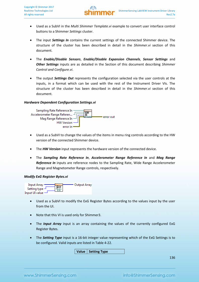
Copyright © Shimmer 2017
Realtime Technologies Ltd ShimmerSensing LabVIEW Instrument Driver Library
All rights reserved Rev2.7a
136
Used as a SubVI in the Multi Shimmer Template.vi example to convert user interface control
buttons to a Shimmer Settings cluster.
The input Settings In contains the current settings of the connected Shimmer device. The
structure of the cluster has been described in detail in the Shimmer.vi section of this
document.
The Enable/Disable Sensors, Enable/Disable Expansion Channels, Sensor Settings and
Other Settings inputs are as detailed in the Section of this document describing Shimmer
Control and Configure.vi.
The output Settings Out represents the configuration selected via the user controls at the
inputs, in a format which can be used with the rest of the Instrument Driver VIs. The
structure of the cluster has been described in detail in the Shimmer.vi section of this
document.
Hardware Dependent Configuration Settings.vi
Used as a SubVI to change the values of the items in menu ring controls according to the HW
version of the connected Shimmer device.
The HW Version input represents the hardware version of the connected device.
The Sampling Rate Reference In, Accelerometer Range Reference In and Mag Range
Reference In inputs are reference nodes to the Sampling Rate, Wide Range Accelerometer
Range and Magnetometer Range controls, respectively.
Modify ExG Register Bytes.vi
Used as a SubVI to modify the ExG Register Bytes according to the values input by the user
from the UI.
Note that this VI is used only for Shimmer3.
The Input Array input is an array containing the values of the currently configured ExG
Register Bytes.
The Setting Type input is a 16-bit integer value representing which of the ExG Settings is to
be configured. Valid inputs are listed in Table 4-22.
Value Setting Type
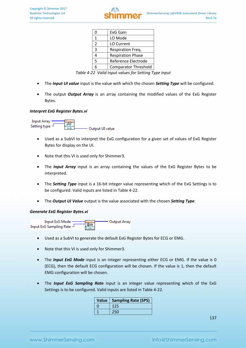
Copyright © Shimmer 2017
Realtime Technologies Ltd ShimmerSensing LabVIEW Instrument Driver Library
All rights reserved Rev2.7a
137
0 ExG Gain
1 LO Mode
2 LO Current
3 Respiration Freq.
4 Respiration Phase
5 Reference Electrode
6 Comparator Threshold
Table 4-22 Valid input values for Setting Type input
The Input UI value input is the value with which the chosen Setting Type will be configured.
The output Output Array is an array containing the modified values of the ExG Register
Bytes.
Interpret ExG Register Bytes.vi
Used as a SubVI to interpret the ExG configuration for a given set of values of ExG Register
Bytes for display on the UI.
Note that this VI is used only for Shimmer3.
The Input Array input is an array containing the values of the ExG Register Bytes to be
interpreted.
The Setting Type input is a 16-bit integer value representing which of the ExG Settings is to
be configured. Valid inputs are listed in Table 4-22.
The Output UI Value output is the value associated with the chosen Setting Type.
Generate ExG Register Bytes.vi
Used as a SubVI to generate the default ExG Register Bytes for ECG or EMG.
Note that this VI is used only for Shimmer3.
The Input ExG Mode input is an integer representing either ECG or EMG. If the value is 0
(ECG), then the default ECG configuration will be chosen. If the value is 1, then the default
EMG configuration will be chosen.
The Input ExG Sampling Rate input is an integer value representing which of the ExG
Settings is to be configured. Valid inputs are listed in Table 4-22.
Value Sampling Rate (SPS)
0 125
1 250
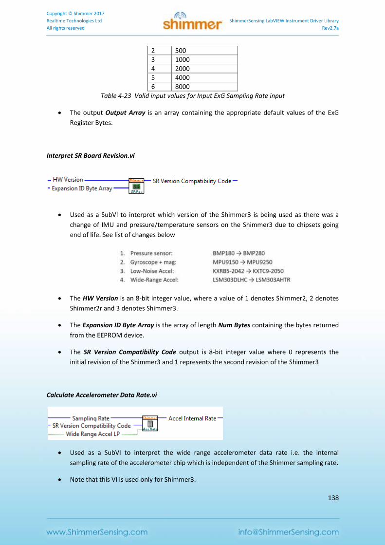
Copyright © Shimmer 2017
Realtime Technologies Ltd ShimmerSensing LabVIEW Instrument Driver Library
All rights reserved Rev2.7a
138
2 500
3 1000
4 2000
5 4000
6 8000
Table 4-23 Valid input values for Input ExG Sampling Rate input
The output Output Array is an array containing the appropriate default values of the ExG
Register Bytes.
Interpret SR Board Revision.vi
Used as a SubVI to interpret which version of the Shimmer3 is being used as there was a
change of IMU and pressure/temperature sensors on the Shimmer3 due to chipsets going
end of life. See list of changes below
The HW Version is an 8-bit integer value, where a value of 1 denotes Shimmer2, 2 denotes
Shimmer2r and 3 denotes Shimmer3.
The Expansion ID Byte Array is the array of length Num Bytes containing the bytes returned
from the EEPROM device.
The SR Version Compatibility Code output is 8-bit integer value where 0 represents the
initial revision of the Shimmer3 and 1 represents the second revision of the Shimmer3
Calculate Accelerometer Data Rate.vi
Used as a SubVI to interpret the wide range accelerometer data rate i.e. the internal
sampling rate of the accelerometer chip which is independent of the Shimmer sampling rate.
Note that this VI is used only for Shimmer3.
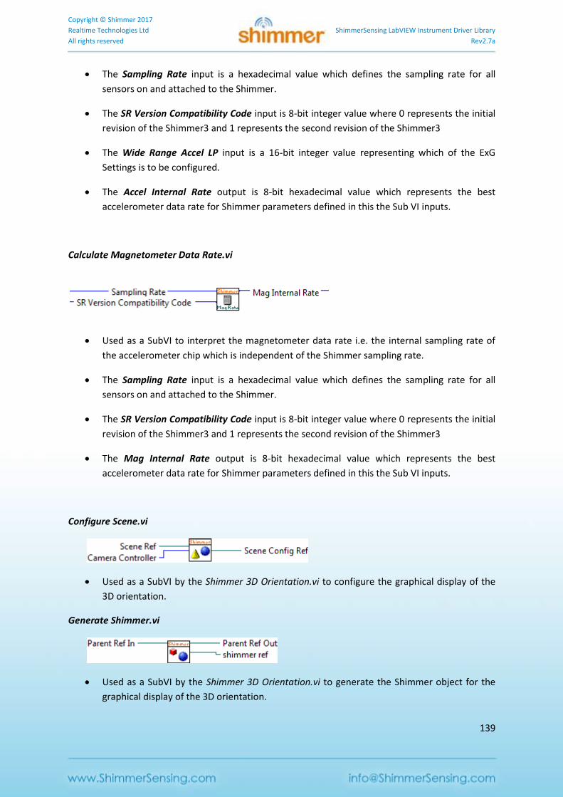
Copyright © Shimmer 2017
Realtime Technologies Ltd ShimmerSensing LabVIEW Instrument Driver Library
All rights reserved Rev2.7a
139
The Sampling Rate input is a hexadecimal value which defines the sampling rate for all
sensors on and attached to the Shimmer.
The SR Version Compatibility Code input is 8-bit integer value where 0 represents the initial
revision of the Shimmer3 and 1 represents the second revision of the Shimmer3
The Wide Range Accel LP input is a 16-bit integer value representing which of the ExG
Settings is to be configured.
The Accel Internal Rate output is 8-bit hexadecimal value which represents the best
accelerometer data rate for Shimmer parameters defined in this the Sub VI inputs.
Calculate Magnetometer Data Rate.vi
Used as a SubVI to interpret the magnetometer data rate i.e. the internal sampling rate of
the accelerometer chip which is independent of the Shimmer sampling rate.
The Sampling Rate input is a hexadecimal value which defines the sampling rate for all
sensors on and attached to the Shimmer.
The SR Version Compatibility Code input is 8-bit integer value where 0 represents the initial
revision of the Shimmer3 and 1 represents the second revision of the Shimmer3
The Mag Internal Rate output is 8-bit hexadecimal value which represents the best
accelerometer data rate for Shimmer parameters defined in this the Sub VI inputs.
Configure Scene.vi
Used as a SubVI by the Shimmer 3D Orientation.vi to configure the graphical display of the
3D orientation.
Generate Shimmer.vi
Used as a SubVI by the Shimmer 3D Orientation.vi to generate the Shimmer object for the
graphical display of the 3D orientation.
Copyright © Shimmer 2017
Realtime Technologies Ltd ShimmerSensing LabVIEW Instrument Driver Library
All rights reserved Rev2.7a
140
Close VI
The Close VI is a VI to terminate the communication with the Shimmer device.
Close.vi
Terminates a serial port connection with the Shimmer defined at the input COM Port In.
4.5. PPGtoHeartRateConverter Class
The ShimmerSensing Library contains a class library for converting photoplethysmogram (PPG)
signals from an optical pulse sensor to heart rate (HR) in beats per minute. This class library should
be used to develop applications which rely on the Optical Pulse Sensing Probe hardware from
Shimmer. The implementation of the PPG to HR conversion algorithm is not available open source,
so the implementation of the class library's VIs is protected. Users should leverage the Shimmer with
Optical HR.vi example, which was described in the Example Application VIs section of this document,
to develop applications with the PPGtoHeartRateConverter class.
Member variables
Figure 4-39 shows the input member variables of the PPGtoHeartRateConverter class. The inputs to
the class are as follows:
Reset is a Boolean value which should be set to True whenever a new data set is passed to
the class for conversion. When the value is true, the data buffers will be cleared. Otherwise
the value should be false and the data buffers will be maintained. A Write Access VI is
provided for this input. Alternatively, the Set Input Data From Arrays.vi or the Set Input Data
From Stream.vi can be used to access this input.
HW Version represents the hardware version of the Shimmer device from which the PPG
data is sampled and is the same as the equivalent setting in the Shimmer Settings cluster. A
Write Access VI is provided for this input. Alternatively, the Set Input Data From Arrays.vi or
the Set Input Data From Stream.vi can be used to access this input.
Sampling Rate represents the sampling rate at which the PPG data is sampled and is the
same as the equivalent setting in the Shimmer Settings cluster. A Write Access VI is provided
for this input. Alternatively, the Set Input Data From Arrays.vi or the Set Input Data From
Stream.vi can be used to access this input.
Num beats to average is an integer value that represents the number of detected heart
beats that will be taken into account to estimate the heart rate from the PPG signal. The
minimum valid value is 1. Increasing the value of this parameter will produce a smoother
heart rate output but will mean that the algorithm will take longer to recover from
interference in the PPG signal due to motion or other sources. A Write Access VI is provided
for this input. Alternatively, the Set Input Data From Arrays.vi or the Set Input Data From
Stream.vi can be used to access this input.
Timestamp Data is an array containing the calibrated Shimmer timestamps for the PPG data.
This array should be used if PPG data is provided from a file, rather than streamed in real-
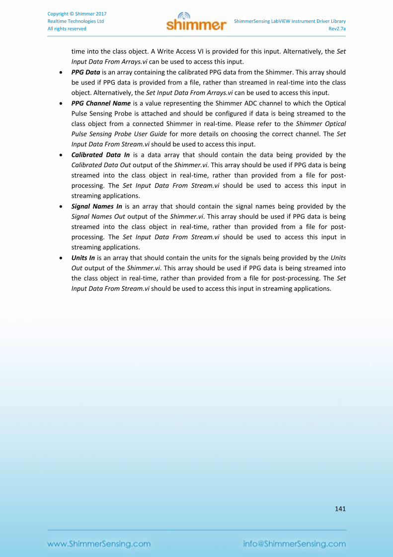
Copyright © Shimmer 2017
Realtime Technologies Ltd ShimmerSensing LabVIEW Instrument Driver Library
All rights reserved Rev2.7a
141
time into the class object. A Write Access VI is provided for this input. Alternatively, the Set
Input Data From Arrays.vi can be used to access this input.
PPG Data is an array containing the calibrated PPG data from the Shimmer. This array should
be used if PPG data is provided from a file, rather than streamed in real-time into the class
object. Alternatively, the Set Input Data From Arrays.vi can be used to access this input.
PPG Channel Name is a value representing the Shimmer ADC channel to which the Optical
Pulse Sensing Probe is attached and should be configured if data is being streamed to the
class object from a connected Shimmer in real-time. Please refer to the Shimmer Optical
Pulse Sensing Probe User Guide for more details on choosing the correct channel. The Set
Input Data From Stream.vi should be used to access this input.
Calibrated Data In is a data array that should contain the data being provided by the
Calibrated Data Out output of the Shimmer.vi. This array should be used if PPG data is being
streamed into the class object in real-time, rather than provided from a file for post-
processing. The Set Input Data From Stream.vi should be used to access this input in
streaming applications.
Signal Names In is an array that should contain the signal names being provided by the
Signal Names Out output of the Shimmer.vi. This array should be used if PPG data is being
streamed into the class object in real-time, rather than provided from a file for post-
processing. The Set Input Data From Stream.vi should be used to access this input in
streaming applications.
Units In is an array that should contain the units for the signals being provided by the Units
Out output of the Shimmer.vi. This array should be used if PPG data is being streamed into
the class object in real-time, rather than provided from a file for post-processing. The Set
Input Data From Stream.vi should be used to access this input in streaming applications.
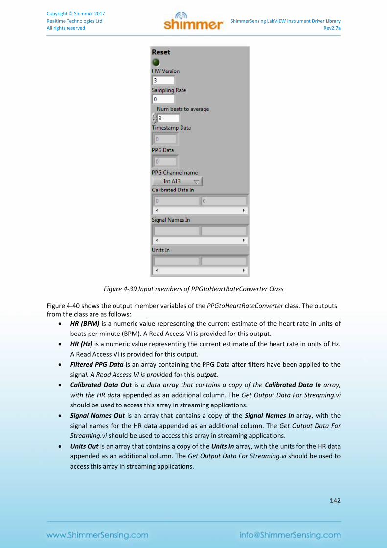
Copyright © Shimmer 2017
Realtime Technologies Ltd ShimmerSensing LabVIEW Instrument Driver Library
All rights reserved Rev2.7a
142
Figure 4-39 Input members of PPGtoHeartRateConverter Class
Figure 4-40 shows the output member variables of the PPGtoHeartRateConverter class. The outputs from the class are as follows:
HR (BPM) is a numeric value representing the current estimate of the heart rate in units of
beats per minute (BPM). A Read Access VI is provided for this output.
HR (Hz) is a numeric value representing the current estimate of the heart rate in units of Hz.
A Read Access VI is provided for this output.
Filtered PPG Data is an array containing the PPG Data after filters have been applied to the
signal. A Read Access VI is provided for this output.
Calibrated Data Out is a data array that contains a copy of the Calibrated Data In array,
with the HR data appended as an additional column. The Get Output Data For Streaming.vi
should be used to access this array in streaming applications.
Signal Names Out is an array that contains a copy of the Signal Names In array, with the
signal names for the HR data appended as an additional column. The Get Output Data For
Streaming.vi should be used to access this array in streaming applications.
Units Out is an array that contains a copy of the Units In array, with the units for the HR data
appended as an additional column. The Get Output Data For Streaming.vi should be used to
access this array in streaming applications.
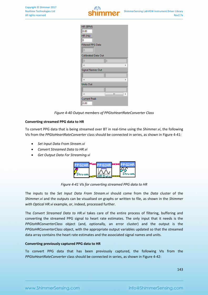
Copyright © Shimmer 2017
Realtime Technologies Ltd ShimmerSensing LabVIEW Instrument Driver Library
All rights reserved Rev2.7a
143
Figure 4-40 Output members of PPGtoHeartRateConverter Class
Converting streamed PPG data to HR
To convert PPG data that is being streamed over BT in real-time using the Shimmer.vi, the following
VIs from the PPGtoHeartRateConverter class should be connected in series, as shown in Figure 4-41:
Set Input Data From Stream.vi
Convert Streamed Data to HR.vi
Get Output Data For Streaming.vi
Figure 4-41 VIs for converting streamed PPG data to HR
The inputs to the Set Input Data From Stream.vi should come from the Data cluster of the
Shimmer.vi and the outputs can be visualised on graphs or written to file, as shown in the Shimmer
with Optical HR.vi example, or, indeed, processed further.
The Convert Streamed Data to HR.vi takes care of the entire process of filtering, buffering and
converting the streamed PPG signal to heart rate estimates. The only input that it needs is the
PPGtoHRConverterClass object (and, optionally, an error cluster) and the output is the
PPGtoHRConverterClass object, with the appropriate output variables updated so that the streamed
data array contains the heart rate estimates and the associated signal names and units.
Converting previously captured PPG data to HR
To convert PPG data that has been previously captured, the following VIs from the
PPGtoHeartRateConverter class should be connected in series, as shown in Figure 4-42:
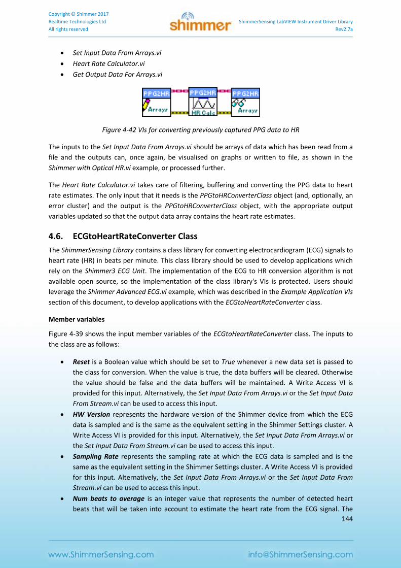
Copyright © Shimmer 2017
Realtime Technologies Ltd ShimmerSensing LabVIEW Instrument Driver Library
All rights reserved Rev2.7a
144
Set Input Data From Arrays.vi
Heart Rate Calculator.vi
Get Output Data For Arrays.vi
Figure 4-42 VIs for converting previously captured PPG data to HR
The inputs to the Set Input Data From Arrays.vi should be arrays of data which has been read from a
file and the outputs can, once again, be visualised on graphs or written to file, as shown in the
Shimmer with Optical HR.vi example, or processed further.
The Heart Rate Calculator.vi takes care of filtering, buffering and converting the PPG data to heart
rate estimates. The only input that it needs is the PPGtoHRConverterClass object (and, optionally, an
error cluster) and the output is the PPGtoHRConverterClass object, with the appropriate output
variables updated so that the output data array contains the heart rate estimates.
4.6. ECGtoHeartRateConverter Class
The ShimmerSensing Library contains a class library for converting electrocardiogram (ECG) signals to
heart rate (HR) in beats per minute. This class library should be used to develop applications which
rely on the Shimmer3 ECG Unit. The implementation of the ECG to HR conversion algorithm is not
available open source, so the implementation of the class library's VIs is protected. Users should
leverage the Shimmer Advanced ECG.vi example, which was described in the Example Application VIs
section of this document, to develop applications with the ECGtoHeartRateConverter class.
Member variables
Figure 4-39 shows the input member variables of the ECGtoHeartRateConverter class. The inputs to
the class are as follows:
Reset is a Boolean value which should be set to True whenever a new data set is passed to
the class for conversion. When the value is true, the data buffers will be cleared. Otherwise
the value should be false and the data buffers will be maintained. A Write Access VI is
provided for this input. Alternatively, the Set Input Data From Arrays.vi or the Set Input Data
From Stream.vi can be used to access this input.
HW Version represents the hardware version of the Shimmer device from which the ECG
data is sampled and is the same as the equivalent setting in the Shimmer Settings cluster. A
Write Access VI is provided for this input. Alternatively, the Set Input Data From Arrays.vi or
the Set Input Data From Stream.vi can be used to access this input.
Sampling Rate represents the sampling rate at which the ECG data is sampled and is the
same as the equivalent setting in the Shimmer Settings cluster. A Write Access VI is provided
for this input. Alternatively, the Set Input Data From Arrays.vi or the Set Input Data From
Stream.vi can be used to access this input.
Num beats to average is an integer value that represents the number of detected heart
beats that will be taken into account to estimate the heart rate from the ECG signal. The
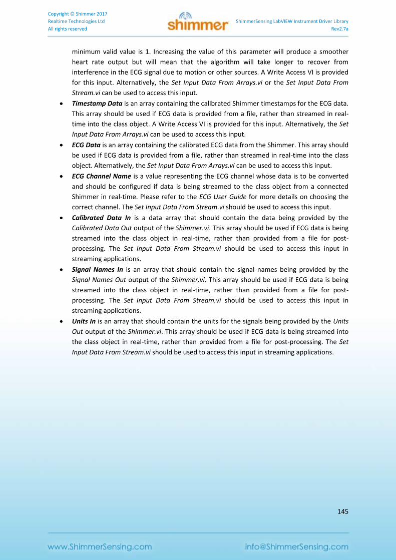
Copyright © Shimmer 2017
Realtime Technologies Ltd ShimmerSensing LabVIEW Instrument Driver Library
All rights reserved Rev2.7a
145
minimum valid value is 1. Increasing the value of this parameter will produce a smoother
heart rate output but will mean that the algorithm will take longer to recover from
interference in the ECG signal due to motion or other sources. A Write Access VI is provided
for this input. Alternatively, the Set Input Data From Arrays.vi or the Set Input Data From
Stream.vi can be used to access this input.
Timestamp Data is an array containing the calibrated Shimmer timestamps for the ECG data.
This array should be used if ECG data is provided from a file, rather than streamed in real-
time into the class object. A Write Access VI is provided for this input. Alternatively, the Set
Input Data From Arrays.vi can be used to access this input.
ECG Data is an array containing the calibrated ECG data from the Shimmer. This array should
be used if ECG data is provided from a file, rather than streamed in real-time into the class
object. Alternatively, the Set Input Data From Arrays.vi can be used to access this input.
ECG Channel Name is a value representing the ECG channel whose data is to be converted
and should be configured if data is being streamed to the class object from a connected
Shimmer in real-time. Please refer to the ECG User Guide for more details on choosing the
correct channel. The Set Input Data From Stream.vi should be used to access this input.
Calibrated Data In is a data array that should contain the data being provided by the
Calibrated Data Out output of the Shimmer.vi. This array should be used if ECG data is being
streamed into the class object in real-time, rather than provided from a file for post-
processing. The Set Input Data From Stream.vi should be used to access this input in
streaming applications.
Signal Names In is an array that should contain the signal names being provided by the
Signal Names Out output of the Shimmer.vi. This array should be used if ECG data is being
streamed into the class object in real-time, rather than provided from a file for post-
processing. The Set Input Data From Stream.vi should be used to access this input in
streaming applications.
Units In is an array that should contain the units for the signals being provided by the Units
Out output of the Shimmer.vi. This array should be used if ECG data is being streamed into
the class object in real-time, rather than provided from a file for post-processing. The Set
Input Data From Stream.vi should be used to access this input in streaming applications.
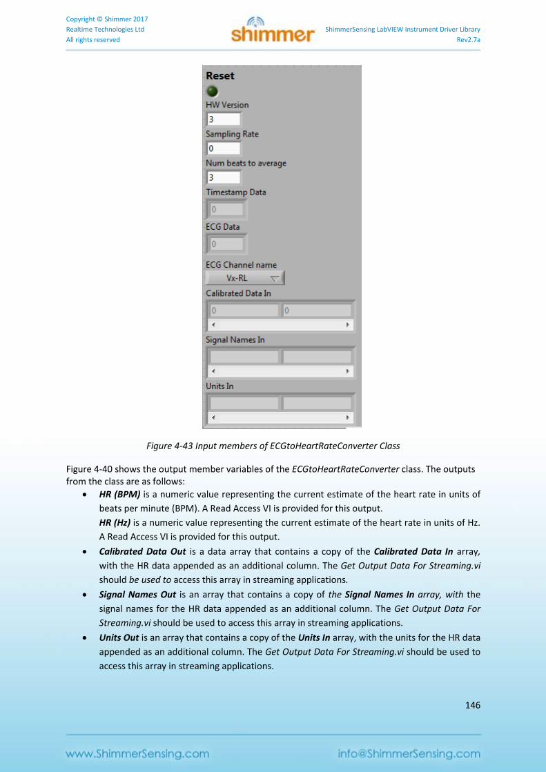
Copyright © Shimmer 2017
Realtime Technologies Ltd ShimmerSensing LabVIEW Instrument Driver Library
All rights reserved Rev2.7a
146
Figure 4-43 Input members of ECGtoHeartRateConverter Class
Figure 4-40 shows the output member variables of the ECGtoHeartRateConverter class. The outputs from the class are as follows:
HR (BPM) is a numeric value representing the current estimate of the heart rate in units of
beats per minute (BPM). A Read Access VI is provided for this output.
HR (Hz) is a numeric value representing the current estimate of the heart rate in units of Hz.
A Read Access VI is provided for this output.
Calibrated Data Out is a data array that contains a copy of the Calibrated Data In array,
with the HR data appended as an additional column. The Get Output Data For Streaming.vi
should be used to access this array in streaming applications.
Signal Names Out is an array that contains a copy of the Signal Names In array, with the
signal names for the HR data appended as an additional column. The Get Output Data For
Streaming.vi should be used to access this array in streaming applications.
Units Out is an array that contains a copy of the Units In array, with the units for the HR data
appended as an additional column. The Get Output Data For Streaming.vi should be used to
access this array in streaming applications.
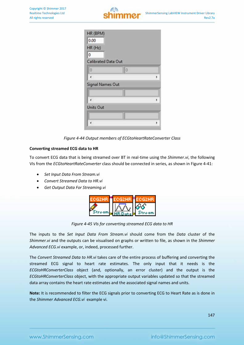
Copyright © Shimmer 2017
Realtime Technologies Ltd ShimmerSensing LabVIEW Instrument Driver Library
All rights reserved Rev2.7a
147
Figure 4-44 Output members of ECGtoHeartRateConverter Class
Converting streamed ECG data to HR
To convert ECG data that is being streamed over BT in real-time using the Shimmer.vi, the following
VIs from the ECGtoHeartRateConverter class should be connected in series, as shown in Figure 4-41:
Set Input Data From Stream.vi
Convert Streamed Data to HR.vi
Get Output Data For Streaming.vi
Figure 4-45 VIs for converting streamed ECG data to HR
The inputs to the Set Input Data From Stream.vi should come from the Data cluster of the
Shimmer.vi and the outputs can be visualised on graphs or written to file, as shown in the Shimmer
Advanced ECG.vi example, or, indeed, processed further.
The Convert Streamed Data to HR.vi takes care of the entire process of buffering and converting the
streamed ECG signal to heart rate estimates. The only input that it needs is the
ECGtoHRConverterClass object (and, optionally, an error cluster) and the output is the
ECGtoHRConverterClass object, with the appropriate output variables updated so that the streamed
data array contains the heart rate estimates and the associated signal names and units.
Note: It is recommended to filter the ECG signals prior to converting ECG to Heart Rate as is done in
the Shimmer Advanced ECG.vi example vi.
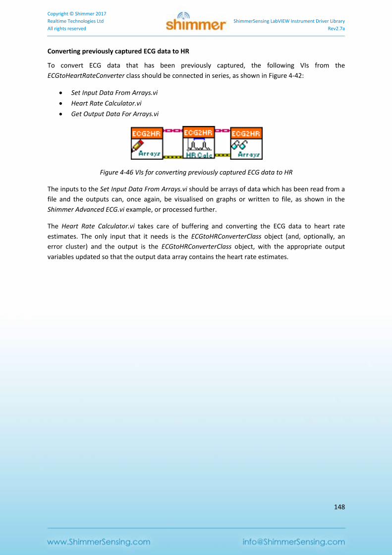
Copyright © Shimmer 2017
Realtime Technologies Ltd ShimmerSensing LabVIEW Instrument Driver Library
All rights reserved Rev2.7a
148
Converting previously captured ECG data to HR
To convert ECG data that has been previously captured, the following VIs from the
ECGtoHeartRateConverter class should be connected in series, as shown in Figure 4-42:
Set Input Data From Arrays.vi
Heart Rate Calculator.vi
Get Output Data For Arrays.vi
Figure 4-46 VIs for converting previously captured ECG data to HR
The inputs to the Set Input Data From Arrays.vi should be arrays of data which has been read from a
file and the outputs can, once again, be visualised on graphs or written to file, as shown in the
Shimmer Advanced ECG.vi example, or processed further.
The Heart Rate Calculator.vi takes care of buffering and converting the ECG data to heart rate
estimates. The only input that it needs is the ECGtoHRConverterClass object (and, optionally, an
error cluster) and the output is the ECGtoHRConverterClass object, with the appropriate output
variables updated so that the output data array contains the heart rate estimates.
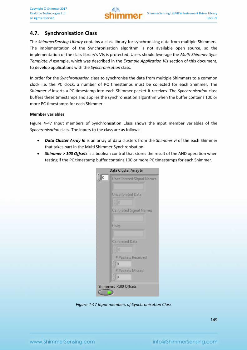
Copyright © Shimmer 2017
Realtime Technologies Ltd ShimmerSensing LabVIEW Instrument Driver Library
All rights reserved Rev2.7a
149
4.7. Synchronisation Class
The ShimmerSensing Library contains a class library for synchronising data from multiple Shimmers.
The implementation of the Synchronisation algorithm is not available open source, so the
implementation of the class library's VIs is protected. Users should leverage the Multi Shimmer Sync
Template.vi example, which was described in the Example Application VIs section of this document,
to develop applications with the Synchronisation class.
In order for the Synchronisation class to synchronise the data from multiple Shimmers to a common
clock i.e. the PC clock, a number of PC timestamps must be collected for each Shimmer. The
Shimmer.vi inserts a PC timestamp into each Shimmer packet it receives. The Synchronisation class
buffers these timestamps and applies the synchronisation algorithm when the buffer contains 100 or
more PC timestamps for each Shimmer.
Member variables
Figure 4-47 Input members of Synchronisation Class shows the input member variables of the
Synchronisation class. The inputs to the class are as follows:
Data Cluster Array In is an array of data clusters from the Shimmer.vi of the each Shimmer
that takes part in the Multi Shimmer Synchronisation.
Shimmer > 100 Offsets is a boolean control that stores the result of the AND operation when
testing if the PC timestamp buffer contains 100 or more PC timestamps for each Shimmer.
Figure 4-47 Input members of Synchronisation Class
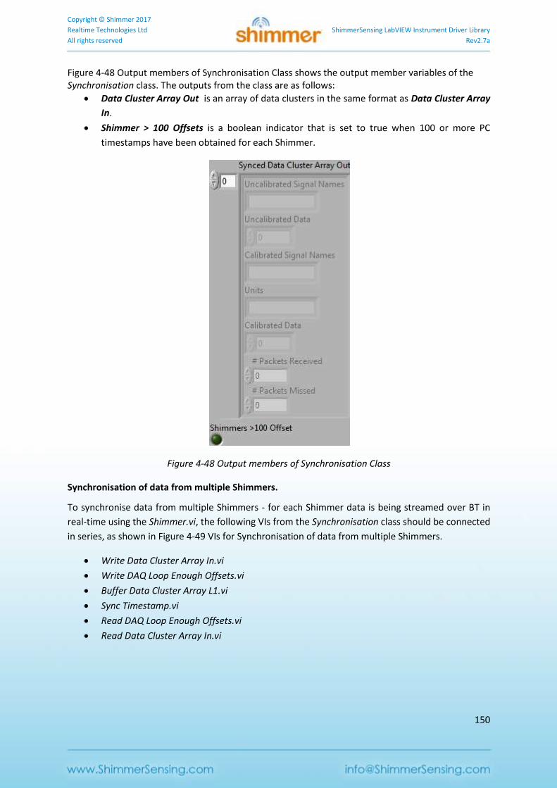
Copyright © Shimmer 2017
Realtime Technologies Ltd ShimmerSensing LabVIEW Instrument Driver Library
All rights reserved Rev2.7a
150
Figure 4-48 Output members of Synchronisation Class shows the output member variables of the Synchronisation class. The outputs from the class are as follows:
Data Cluster Array Out is an array of data clusters in the same format as Data Cluster Array
In.
Shimmer > 100 Offsets is a boolean indicator that is set to true when 100 or more PC
timestamps have been obtained for each Shimmer.
Figure 4-48 Output members of Synchronisation Class
Synchronisation of data from multiple Shimmers.
To synchronise data from multiple Shimmers - for each Shimmer data is being streamed over BT in
real-time using the Shimmer.vi, the following VIs from the Synchronisation class should be connected
in series, as shown in Figure 4-49 VIs for Synchronisation of data from multiple Shimmers.
Write Data Cluster Array In.vi
Write DAQ Loop Enough Offsets.vi
Buffer Data Cluster Array L1.vi
Sync Timestamp.vi
Read DAQ Loop Enough Offsets.vi
Read Data Cluster Array In.vi
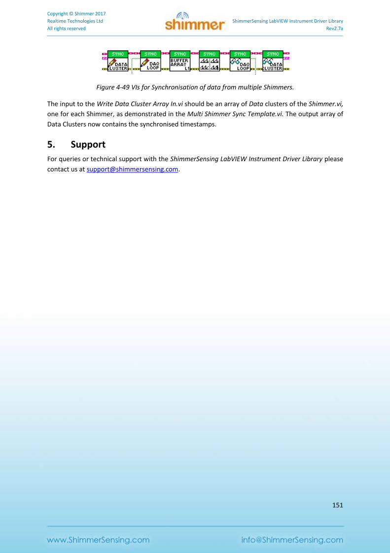
Copyright © Shimmer 2017
Realtime Technologies Ltd ShimmerSensing LabVIEW Instrument Driver Library
All rights reserved Rev2.7a
151
Figure 4-49 VIs for Synchronisation of data from multiple Shimmers.
The input to the Write Data Cluster Array In.vi should be an array of Data clusters of the Shimmer.vi,
one for each Shimmer, as demonstrated in the Multi Shimmer Sync Template.vi. The output array of
Data Clusters now contains the synchronised timestamps.
5. Support
For queries or technical support with the ShimmerSensing LabVIEW Instrument Driver Library please
contact us at [email protected].
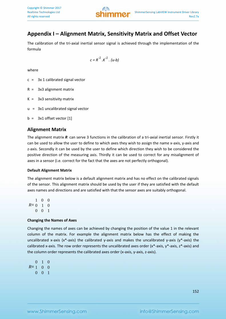
Copyright © Shimmer 2017
Realtime Technologies Ltd ShimmerSensing LabVIEW Instrument Driver Library
All rights reserved Rev2.7a
152
Appendix I – Alignment Matrix, Sensitivity Matrix and Offset Vector
The calibration of the tri-axial inertial sensor signal is achieved through the implementation of the
formula
c = R-1
.K-1
. (u-b)
where
c = 3x 1 calibrated signal vector
R = 3x3 alignment matrix
K = 3x3 sensitivity matrix
u = 3x1 uncalibrated signal vector
b = 3x1 offset vector [1]
Alignment Matrix
The alignment matrix R can serve 3 functions in the calibration of a tri-axial inertial sensor. Firstly it
can be used to allow the user to define to which axes they wish to assign the name x-axis, y-axis and
z-axis. Secondly it can be used by the user to define which direction they wish to be considered the
positive direction of the measuring axis. Thirdly it can be used to correct for any misalignment of
axes in a sensor (i.e. correct for the fact that the axes are not perfectly orthogonal).
Default Alignment Matrix
The alignment matrix below is a default alignment matrix and has no effect on the calibrated signals
of the sensor. This alignment matrix should be used by the user if they are satisfied with the default
axes names and directions and are satisfied with that the sensor axes are suitably orthogonal.
Changing the Names of Axes
Changing the names of axes can be achieved by changing the position of the value 1 in the relevant
column of the matrix. For example the alignment matrix below has the effect of making the
uncalibrated x-axis (x*-axis) the calibrated y-axis and makes the uncalibrated y-axis (y*-axis) the
calibrated x-axis. The row order represents the uncalibrated axes order (x*-axis, y*-axis, z*-axis) and
the column order represents the calibrated axes order (x-axis, y-axis, z-axis).
R=1 0 0
0 1 0
0 0 1
R=0 1 0
1 0 0
0 0 1
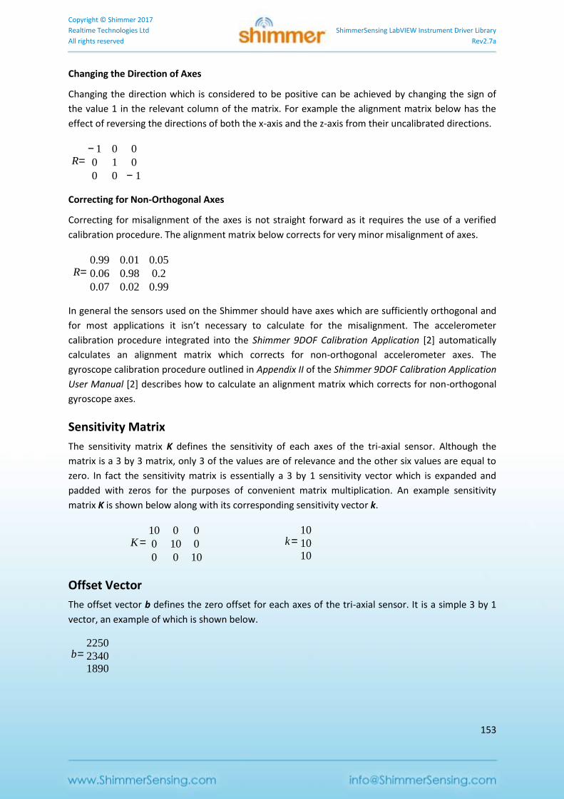
Copyright © Shimmer 2017
Realtime Technologies Ltd ShimmerSensing LabVIEW Instrument Driver Library
All rights reserved Rev2.7a
153
Changing the Direction of Axes
Changing the direction which is considered to be positive can be achieved by changing the sign of
the value 1 in the relevant column of the matrix. For example the alignment matrix below has the
effect of reversing the directions of both the x-axis and the z-axis from their uncalibrated directions.
Correcting for Non-Orthogonal Axes
Correcting for misalignment of the axes is not straight forward as it requires the use of a verified
calibration procedure. The alignment matrix below corrects for very minor misalignment of axes.
In general the sensors used on the Shimmer should have axes which are sufficiently orthogonal and
for most applications it isn’t necessary to calculate for the misalignment. The accelerometer
calibration procedure integrated into the Shimmer 9DOF Calibration Application [2] automatically
calculates an alignment matrix which corrects for non-orthogonal accelerometer axes. The
gyroscope calibration procedure outlined in Appendix II of the Shimmer 9DOF Calibration Application
User Manual [2] describes how to calculate an alignment matrix which corrects for non-orthogonal
gyroscope axes.
Sensitivity Matrix
The sensitivity matrix K defines the sensitivity of each axes of the tri-axial sensor. Although the
matrix is a 3 by 3 matrix, only 3 of the values are of relevance and the other six values are equal to
zero. In fact the sensitivity matrix is essentially a 3 by 1 sensitivity vector which is expanded and
padded with zeros for the purposes of convenient matrix multiplication. An example sensitivity
matrix K is shown below along with its corresponding sensitivity vector k.
Offset Vector
The offset vector b defines the zero offset for each axes of the tri-axial sensor. It is a simple 3 by 1
vector, an example of which is shown below.
R=− 1 0 0
0 1 0
0 0 − 1
R=0.99 0.01 0.05
0.06 0.98 0.2
0.07 0.02 0.99
K=10 0 0
0 10 0
0 0 10
k=10
1010
b=2250
23401890
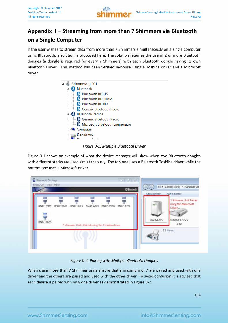
Copyright © Shimmer 2017
Realtime Technologies Ltd ShimmerSensing LabVIEW Instrument Driver Library
All rights reserved Rev2.7a
154
Appendix II – Streaming from more than 7 Shimmers via Bluetooth
on a Single Computer
If the user wishes to stream data from more than 7 Shimmers simultaneously on a single computer
using Bluetooth, a solution is proposed here. The solution requires the use of 2 or more Bluetooth
dongles (a dongle is required for every 7 Shimmers) with each Bluetooth dongle having its own
Bluetooth Driver. This method has been verified in-house using a Toshiba driver and a Microsoft
driver.
Figure 0-1: Multiple Bluetooth Driver
Figure 0-1 shows an example of what the device manager will show when two Bluetooth dongles
with different stacks are used simultaneously. The top one uses a Bluetooth Toshiba driver while the
bottom one uses a Microsoft driver.
Figure 0-2: Pairing with Multiple Bluetooth Dongles
When using more than 7 Shimmer units ensure that a maximum of 7 are paired and used with one
driver and the others are paired and used with the other driver. To avoid confusion it is advised that
each device is paired with only one driver as demonstrated in Figure 0-2.
Copyright © Shimmer 2017
Realtime Technologies Ltd ShimmerSensing LabVIEW Instrument Driver Library
All rights reserved Rev2.7a
155
References
[1] F. Ferraris, U. Grimaldi and M. Parvis, Procedure for effortless in-field calibration of three-axis rate
gyros and accelerometers, Sensors Mater. 7 (1995) (5), pp. 311–330
[2] Shimmer 9DoF Calibration Application available for download from the Shimmer website.

Copyright © Shimmer 2017
Realtime Technologies Ltd ShimmerSensing LabVIEW Instrument Driver Library
All rights reserved Rev2.7a
156