Instruments for Measuring the Electromagnetic Shielding Effectiveness - Harya,Masahiro
Upload
duongkhanhCategory
view
228download
0
Shielding Effectiveness Measurement Application Note
Products:
ı R&S®EMC32-K48
This application note shows all necessary settings for measuring shielding
effectiveness using the R&S®EMC32-K48 option via R&S
®EMC32
Measurement Software.
Note:
Please find the most up-to-date document on our homepage
http://www.rohde-schwarz.com/appnote/
App
licat
ion
Not
e
Jim
my
Goh
8.20
15 –
1.0
0

Table of Contents
1.00 Rohde & Schwarz Shielding Effectiveness Measurement
2
Table of Contents
1 Overview .............................................................................................. 3
2 Introduction ......................................................................................... 4
3 EMC32 Setup ....................................................................................... 5
3.1 Installation of Software and Drivers .......................................................................... 5
3.1.1 EMC32 on the Web........................................................................................................ 5
3.1.2 Update Manager ............................................................................................................ 6
3.2 iKey Requirements ...................................................................................................... 6
3.3 Online Help ................................................................................................................... 6
4 Test Configuration .............................................................................. 7
4.1 Instrumentation ............................................................................................................ 7
4.2 Hardware Setup ............................................................................................................ 9
5 Test Template Configurations ......................................................... 10
5.1 Reference Level Test Templates ..............................................................................10
5.1.1 Reference Level Test Template for SE........................................................................11
5.2 EUT Test Template.....................................................................................................14
5.2.1 EUT Test Template for SE ...........................................................................................15
5.3 EUT Monitoring Template .........................................................................................16
5.3.1 EUT Monitoring Template for SE .................................................................................17
5.3.2 Average Detector for EUT Monitoring..........................................................................18
5.3.3 Limit Line Input for EUT Monitoring .............................................................................19
5.4 EUT Auto Test Template ...........................................................................................20
5.4.1 EUT Auto Test for SE ..................................................................................................21
6 Running of test ................................................................................. 24
6.1 Reference Level Test for SE .....................................................................................24
6.2 EUT Auto Test for SE ................................................................................................28
7 Printing Report .................................................................................. 32
7.1 Printing Report for SE ...............................................................................................32

Overview
1.00 Rohde & Schwarz Shielding Effectiveness Measurement
3
1 Overview
This document describes the functionalities for R&S®EMC32-K48 option in
R&S®EMC32 platform which have to be done to support the shielding effectiveness
test method.
The R&S®EMC32 software offers the following applications:
▪ Provide control for instruments (RF generator, amplifier, switch units,
spectrum analyzer, network analyzer)
▪ Perform reference level testing of system and measurement protocol as
recommended by test standard
▪ Perform EUT Test and Measurement automatically
▪ Evaluate and display real-time value of the measurement
▪ Generate report
The R&S®EMC32-K48 option requires R&S
®EMC32-S Main Option (EMS Scan
Template) and R&S®EMC32-K4 option (EMS Auto Test).
Multi-user licensee should purchase R&S®EMC32MK48 option.
The following abbreviation are used in the following text:
▪ R&S®EMC32 software is referred to as EMC32
▪ R&S®EMC32-S software option is referred to as EMC32-S
▪ R&S®EMC32-K4 software option is referred to as EMC32-K4
▪ R&S®EMC32-K48 software option is referred to as EMC32-K48
▪ R&S®EMC32MK48 software option is referred to as EMC32MK48
▪ Shielding Effectiveness is referred to as SE
▪ Equipment under test is referred to as EUT
▪ Radio frequency is referred to as RF
▪ Electromagnetic interference is referred to as EMI
▪ Electromagnetic susceptibility is referred to as EMS
▪ R&S® refers to Rohde & Schwarz GmbH & Co. KG

Introduction
1.00 Rohde & Schwarz Shielding Effectiveness Measurement
4
2 Introduction
Refer to the general block diagram below on the setup for SE system according to
IEEE STD 299, EN 50147-1 and MIL-STD-188-125-1. EMC32 software is used.
Fig. 2-1: Typical SE system
The system above consists of the following:
ı RF generator as RF signal source generation
ı Amplifiers to magnify signal to increase system dynamic range
ı Antenna sets for transmitting and receiving
ı Spectrum analyzer measuring the received level at a given level of signal source
generated
ı Switching unit which can be used to switch to different amplifiers of different
frequency range capabilities
ı Network analyzer for SE measurement of an enclosure

EMC32 Setup
1.00 Rohde & Schwarz Shielding Effectiveness Measurement
5
3 EMC32 Setup
Follow the instructions below to setup EMC32. The steps are:
ı Installation of software and drivers
ı iKey requirements
ı Online help
3.1 Installation of Software and Drivers
This test is programmed to work with EMC32 version 9.20 and above. Follow the
installation procedures below:
1. Install National Instruments GPIB driver with NI-VISA.
2. Install EMC32 version 9.20 or higher. It is important to check all options for EMI
and EMS.
3. Install iKey application
4. Install VISA and drivers for relevant R&S device (e.g. SMC100A, SMF100A, NRP-
USB, and FSP)
The software can now be launched.
3.1.1 EMC32 on the Web
Do check for the latest version of EMC32 via the help menu. In the main toolbar, select
“?” and click on “EMC32 on the Web”. Alternatively, you may also find the latest update
info at www.emc32.rohde-schwarz.com.
Fig. 3-1: EMC32 on the web

EMC32 Setup
1.00 Rohde & Schwarz Shielding Effectiveness Measurement
6
3.1.2 Update Manager
The EMC32 integrated update manager will automatically prompt whenever there is a
new service patch or version update. You can either enable or disable this update
manager via the help menu by selecting “?” and clicking on “Update Manager” for its
settings.
Fig. 3-2: Update manager
3.2 iKey Requirements
EMC32 uses a physical USB dongle referred to as iKey to run test simulations and
control real equipment. Without the iKey, the EMC32 software can only run test
simulations.
The required iKeys options for SE are EMC32-S (EMS Scan template), EMC32-K4
(EMS Auto-Test) and EMC32-K48 (Shielding Effectiveness Test). EMC32 allows
merging of several options onto one iKey using EMC32 iKey Merge Tool from the EMC
program group. You may refer to the EMC32 installation manual chapter 9 for more
information on using the iKey Merge Tool.
3.3 Online Help
Online help is available on the CD and on the software after installation. Help can be
accessed at any time via the main toolbar by selecting "?" or by pressing the F1 key.

Test Configuration
1.00 Rohde & Schwarz Shielding Effectiveness Measurement
7
4 Test Configuration
Before performing SE measurements in EMC32, setup the test configuration as
described in the following sections:
ı Instrumentation
ı Hardware Setup
4.1 Instrumentation
Refer to chapter 3.3 "Online Help" on page 6. In HTML Help, select the Index tab,
search for "Device list" to show a detailed description on setting up the instruments.
Fig. 4-1: Online help for device list

Test Configuration
1.00 Rohde & Schwarz Shielding Effectiveness Measurement
8
The EMC32 software supports a wide range of spectrum analyzer models, antenna
mast controller, amplifiers and their interlock, and OSP switch units.
Fig. 4-2: Device list dialog box
Test Configuration
1.00 Rohde & Schwarz Shielding Effectiveness Measurement
9
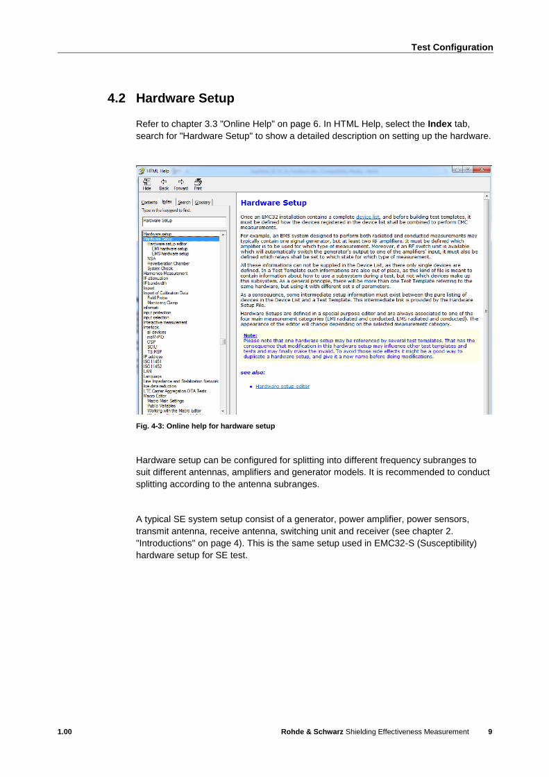
4.2 Hardware Setup
Refer to chapter 3.3 "Online Help" on page 6. In HTML Help, select the Index tab,
search for "Hardware Setup" to show a detailed description on setting up the hardware.
Fig. 4-3: Online help for hardware setup
Hardware setup can be configured for splitting into different frequency subranges to
suit different antennas, amplifiers and generator models. It is recommended to conduct
splitting according to the antenna subranges.
A typical SE system setup consist of a generator, power amplifier, power sensors,
transmit antenna, receive antenna, switching unit and receiver (see chapter 2.
"Introductions" on page 4). This is the same setup used in EMC32-S (Susceptibility)
hardware setup for SE test.

Test Template Configurations
1.00 Rohde & Schwarz Shielding Effectiveness Measurement
10
5 Test Template Configurations
Before performing SE measurements in EMC32, setup the test template configuration
as described in the following sections:
ı Reference Level Test Template
ı EUT Test Template
ı EUT Monitoring Test Template
ı EUT Auto Test Template
5.1 Reference Level Test Templates
Refer to chapter 3.3 "Online Help" on page 6. In HTML Help, select the Index tab,
search for "EMS test new" to show a detailed description on setting up the reference
level test template.
Fig. 5-1: Online help for Reference level test template
Reference level test template, known as reference calibration test template in EMC32,
is required to calibrate a known level at the output of the transmit cable, and to save
the result to a reference calibration table.
The purpose of reference level test for SE is to set a reference for generator level to
achieve SE maximum RF level which is known as reference calibration in EMC32.

Test Template Configurations
1.00 Rohde & Schwarz Shielding Effectiveness Measurement
11
This template is used for the first calibration without EUT. The test template is
configured with several sub-ranges according to the different antennas and also the
antenna sub-ranges.
In EMC32, reference level test is created in EMS scan test template in order to select
the correct hardware setup and run as reference calibration test method to perform
reference level testing.
5.1.1 Reference Level Test Template for SE
This chapter includes some of the parameters that is needed for the reference level
test templates (known as reference calibration in EMC32) to perform the SE test.
For SE reference level measurement, SE test standard will be created in the EMC Test
Standard dropdown box. EMC32-K48 option will be needed to activate the SE test
standard
In Fig. 5-2, select General Settings tab. Under EMC Test Standard, select "SE REF
CAL" from the dropdown list.
Fig. 5-2: Test standard selection for SE

Test Template Configurations
1.00 Rohde & Schwarz Shielding Effectiveness Measurement
12
In Fig. 5-3, select Frequency tab. In the area Start Frequency and Stop Frequency,
enter the appropriate antenna frequency subranges.
Fig. 5-3: Antenna frequency subranges setting
In Fig. 5-4, select Leveling Mode Tab. Under the section Common Ref. Cal. File
Name, enter desired filename in the field below.
Fig. 5-4: Filename entry

Test Template Configurations
1.00 Rohde & Schwarz Shielding Effectiveness Measurement
13
From Fig. 5-5, select Device Setups tab. Click "Span" to bring up the dialog box as
shown in Fig. 4-4. Set Device Mode to "Receiver" to activate zero span measurement
and Detector to "Average".
Fig. 5-5: Span dialog box

Test Template Configurations
1.00 Rohde & Schwarz Shielding Effectiveness Measurement
14
5.2 EUT Test Template
Refer to chapter 3.3 "Online Help" on page 6. In HTML Help, select the Index tab,
search for "EMS test new" to show a detailed description on setting up the EUT test
template.
Fig. 5-6: Online help for creating a new EMS test
This template is used for measurement on the actual EUT. It sets the output transmit
level according to previous reference level results and measure the difference in the
output level from within the EUT. This difference is the shielding effectiveness.
The hardware setup should be preset accordingly (see chapter 4.2 "Hardware Setup
on page 9) before the EUT test sequence can be created in the EMS scan test
template. The EUT test carries out the antenna coupling test using the substitution
method, based on the saved reference calibration table.

Test Template Configurations
1.00 Rohde & Schwarz Shielding Effectiveness Measurement
15
5.2.1 EUT Test Template for SE
For SE test configuration, SE test standard will be created in the EMC Test Standard
dropdown box. EMC32-K48 option will be needed to activate the SE test standard
In Fig. 5-7, select General Settings tab. Under EMC Test Standard, select "SE
TEST" from the dropdown list.
Fig. 5-7: SE test standard selection
For SE requirement, (nominal) immunity level in test measurement should follow its
reference level table to maintain a nearly fixed generator level output for both
horizontal and vertical polarization.

Test Template Configurations
1.00 Rohde & Schwarz Shielding Effectiveness Measurement
16
In Fig. 5-8, select Leveling Mode tab, input any reference calibration table created in
SE REF CAL test template. Target level generator output will follow its reference
calibration generator output hence the Power Control dropdown box will be greyed out.
Take note that SE tests are not run via a normal EMS Scan Test but in EMS Auto Test.
Fig. 5-8: Reference calibration table selection
5.3 EUT Monitoring Template
Refer to chapter 3.3 "Online Help" on page 6. In HTML Help, select the Index tab,
search for "EUT Monitoring" to show a detailed description on setting up the EUT
Monitoring template.
Fig. 5-9: Online help for EUT monitoring

Test Template Configurations
1.00 Rohde & Schwarz Shielding Effectiveness Measurement
17
The main purpose of a EUT measurement is to arrest unwanted failures during
operation by stressing the EUT with a signal. For this purpose, the EUT monitoring
template is necessary to ensure that certain parameters of the EUT are under stress
still behaving as usual. It can also provide the EUT’s worst-case results.
5.3.1 EUT Monitoring Template for SE
The settings of each EUT monitoring channel that use the spectrum analyzer are
configured as follow:
In Fig. 5-10, select Display tab and set the Units to be displayed as "dB". Under the
section Value Conversion, enter the evaluation formula as:
IMMLVL{Imm Lvl dB}-107-MEASVAL{Meas Value}
This is to convert the measured value in dBm and tabulate the effective results in dB.
Fig. 5-10: Evaluation formula for value conversion
Test Template Configurations
1.00 Rohde & Schwarz Shielding Effectiveness Measurement
18
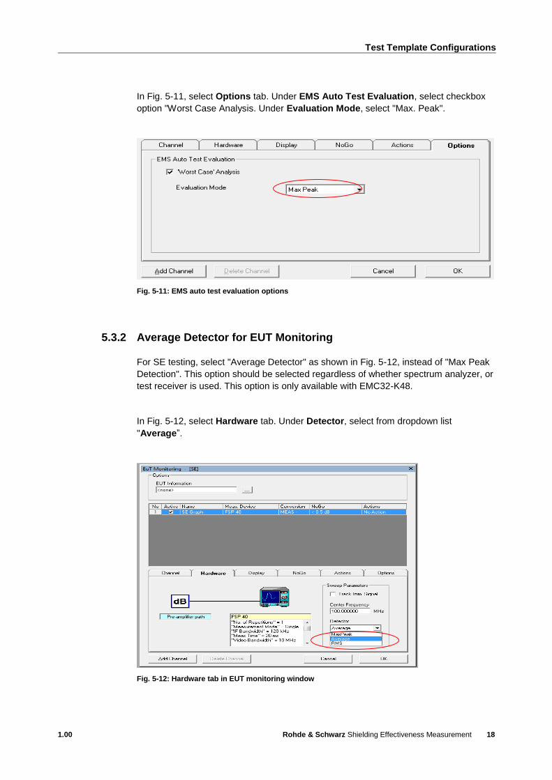
In Fig. 5-11, select Options tab. Under EMS Auto Test Evaluation, select checkbox
option "Worst Case Analysis. Under Evaluation Mode, select "Max. Peak".
Fig. 5-11: EMS auto test evaluation options
5.3.2 Average Detector for EUT Monitoring
For SE testing, select "Average Detector" as shown in Fig. 5-12, instead of "Max Peak
Detection". This option should be selected regardless of whether spectrum analyzer, or
test receiver is used. This option is only available with EMC32-K48.
In Fig. 5-12, select Hardware tab. Under Detector, select from dropdown list
"Average”.
Fig. 5-12: Hardware tab in EUT monitoring window

Test Template Configurations
1.00 Rohde & Schwarz Shielding Effectiveness Measurement
19
5.3.3 Limit Line Input for EUT Monitoring
In EMC32, the NoGo in EUT monitoring defines the limit line for SE. The value of the
limit line must be input in the NoGo tab as shown in Fig. 5-13. The value can either be
a constant value (e.g. 120 dB), or a shape table which consists of different values at
different frequencies.
Fig. 5-13: NoGo tab in EUT Monitoring window
In the NoGo tab, the criteria for pass or fail are defined, with four NoGo types to
choose from:
ı Above Limit: The EUT has failed if the measured (and converted) value is bigger
than a limit value or the value from a limit shape to be defined by the user. This
type will be the preferred setting for SE measurement
ı Below Limit: The EUT has failed if the measured (and converted) value is smaller
than a limit value or the value from a limit shape to be defined by the user.
ı Outside Value Range: The EUT has failed if the measured (and converted) value
is outside of a window of values to be defined by the user.

Test Template Configurations
1.00 Rohde & Schwarz Shielding Effectiveness Measurement
20
ı None: The EUT will never be considered to have failed, the channel is only used
for recording the EUT's parameter.
The limits defined here will be displayed in the graphics window associated to the
channel.
5.4 EUT Auto Test Template
Refer to chapter 3.3 "Online Help" on page 6. In HTML Help, select the Index tab,
search for "EMS Auto Test Template Editor" section to show a detailed description on
setting up the EUT Auto Test template.
Fig. 5-14: Online help for EMS auto test template editor
EUT auto test (known as EMS auto test in EMC32), further enhances the automation
capability of SE test. It allow users to repeat frequency sweeping of EUT measurement
for multiple location, multiple subranges and different polarization when EMC32-K48
option is used. In addition, EUT monitoring template can be used together with EUT
auto test to calculate SE for each location. Worst case analysis feature is also
available to obtain the worst case result over all locations for every frequency point.

Test Template Configurations
1.00 Rohde & Schwarz Shielding Effectiveness Measurement
21
5.4.1 EUT Auto Test for SE
This section shows the configuration for EUT Auto Test for SE Test.
From Fig. 5-15, left-click on Measurement Settings. Enter the same setup as the
EMS Scan template for EUT test.
Fig. 5-15: Measurement settings for EUT auto test

Test Template Configurations
1.00 Rohde & Schwarz Shielding Effectiveness Measurement
22
From Fig. 5-16 left-click on Loop Settings, add polarization and auto test subranges.
Under User Definition Loop Settings, enter the number of antenna positions. The
step number corresponds to the antenna position number. For example, step 1 refers
to antenna position 1.
Select checkbox Visible Column in the Report to display each loop column in the test
report. Select checkbox Show Trace for each Loop Result to show loop result
graphics in the test report.
Fig. 5-16: Loop settings for EUT auto test

Test Template Configurations
1.00 Rohde & Schwarz Shielding Effectiveness Measurement
23
From Fig. 5-17, left-click on Evaluation Settings to show its dialog box. Under EUT
Worst Case Analysis, select checkbox for "Do Worst Case Analysis for EUT
Monitoring Channels".
Fig. 5-17: Evaluation settings for EUT auto test
From Fig. 5-18, left-click on General Settings to open its dialog box. Set the "EUT
Monitoring" file to be used.
Fig. 5-18: General settings for EUT auto test
Running of Test
1.00 Rohde & Schwarz Shielding Effectiveness Measurement
24
6 Running of Test
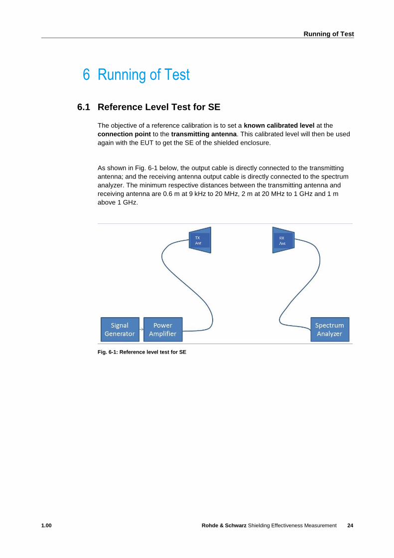
6.1 Reference Level Test for SE
The objective of a reference calibration is to set a known calibrated level at the
connection point to the transmitting antenna. This calibrated level will then be used
again with the EUT to get the SE of the shielded enclosure.
As shown in Fig. 6-1 below, the output cable is directly connected to the transmitting
antenna; and the receiving antenna output cable is directly connected to the spectrum
analyzer. The minimum respective distances between the transmitting antenna and
receiving antenna are 0.6 m at 9 kHz to 20 MHz, 2 m at 20 MHz to 1 GHz and 1 m
above 1 GHz.
Fig. 6-1: Reference level test for SE
Running of Test
1.00 Rohde & Schwarz Shielding Effectiveness Measurement
25
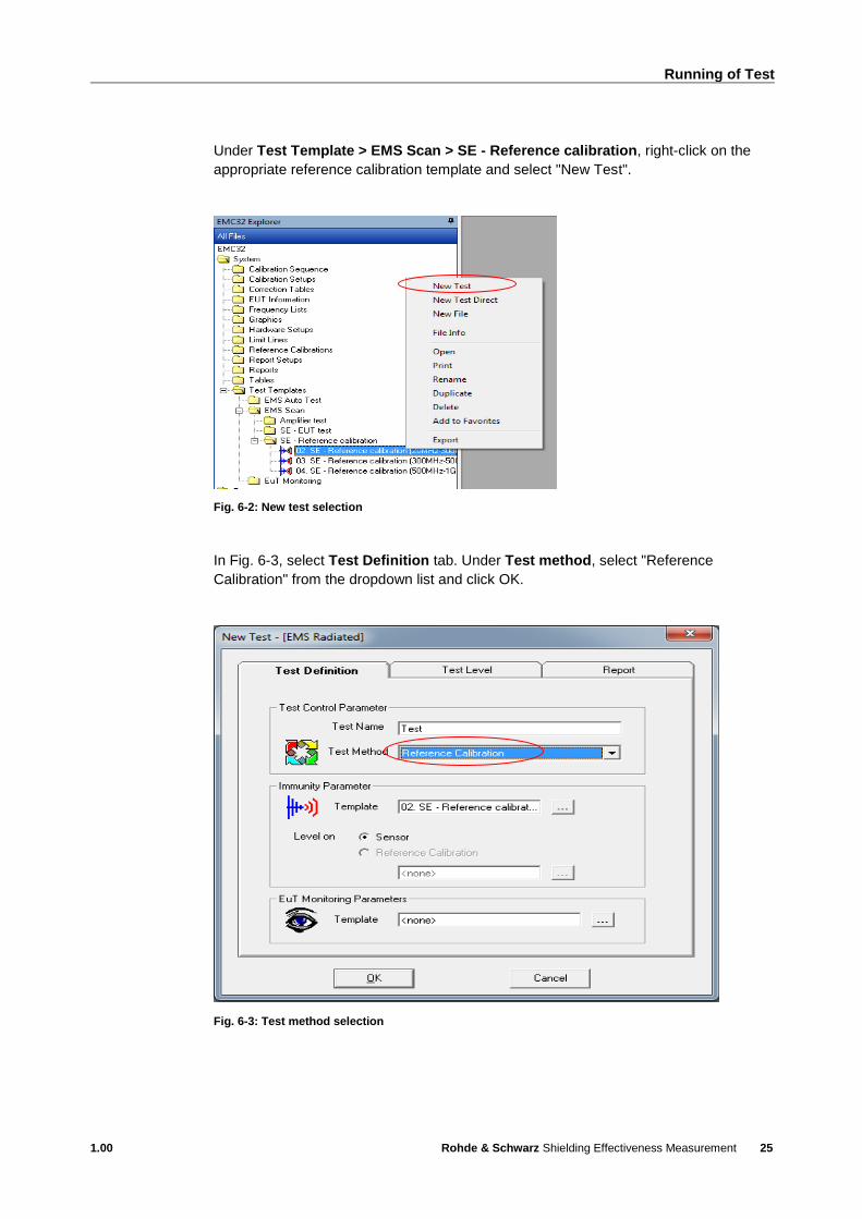
Under Test Template > EMS Scan > SE - Reference calibration, right-click on the
appropriate reference calibration template and select "New Test".
Fig. 6-2: New test selection
In Fig. 6-3, select Test Definition tab. Under Test method, select "Reference
Calibration" from the dropdown list and click OK.
Fig. 6-3: Test method selection
Running of Test
1.00 Rohde & Schwarz Shielding Effectiveness Measurement
26
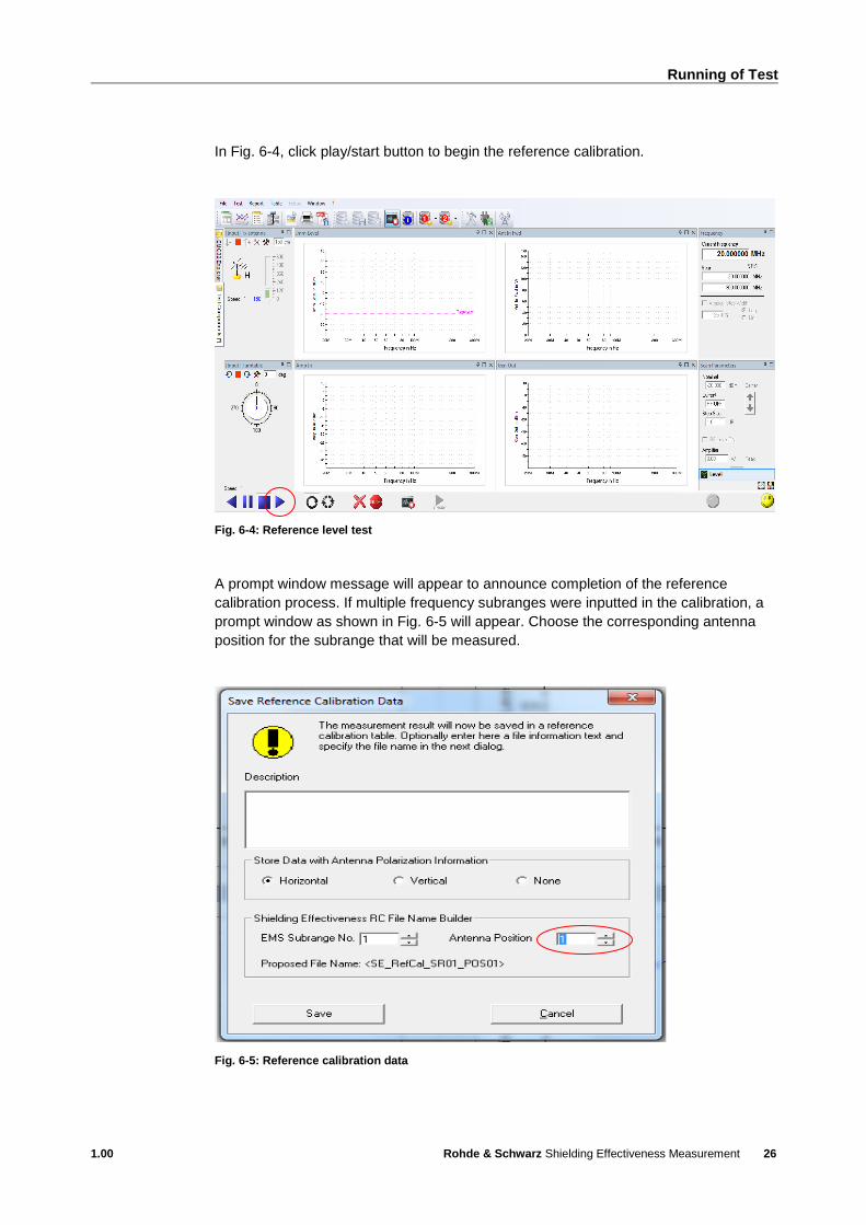
In Fig. 6-4, click play/start button to begin the reference calibration.
Fig. 6-4: Reference level test
A prompt window message will appear to announce completion of the reference
calibration process. If multiple frequency subranges were inputted in the calibration, a
prompt window as shown in Fig. 6-5 will appear. Choose the corresponding antenna
position for the subrange that will be measured.
Fig. 6-5: Reference calibration data

Running of Test
1.00 Rohde & Schwarz Shielding Effectiveness Measurement
27
The naming convention for saving the reference calibration table will be
SE_RC_Name_SR0x_POS0y; where SE_RC_Name is the reference calibration name,
x is the subrange number and y is the antenna position.
Fig. 6-6: Reference calibration filename convention
Save desired reference calibration for all subranges and antenna positions that are to
be tested. Commence with the EUT testing. With the calibration results, the EUT test
can now begin.
Fig. 6-7: Reference calibration result parameters
Running of Test
1.00 Rohde & Schwarz Shielding Effectiveness Measurement
28
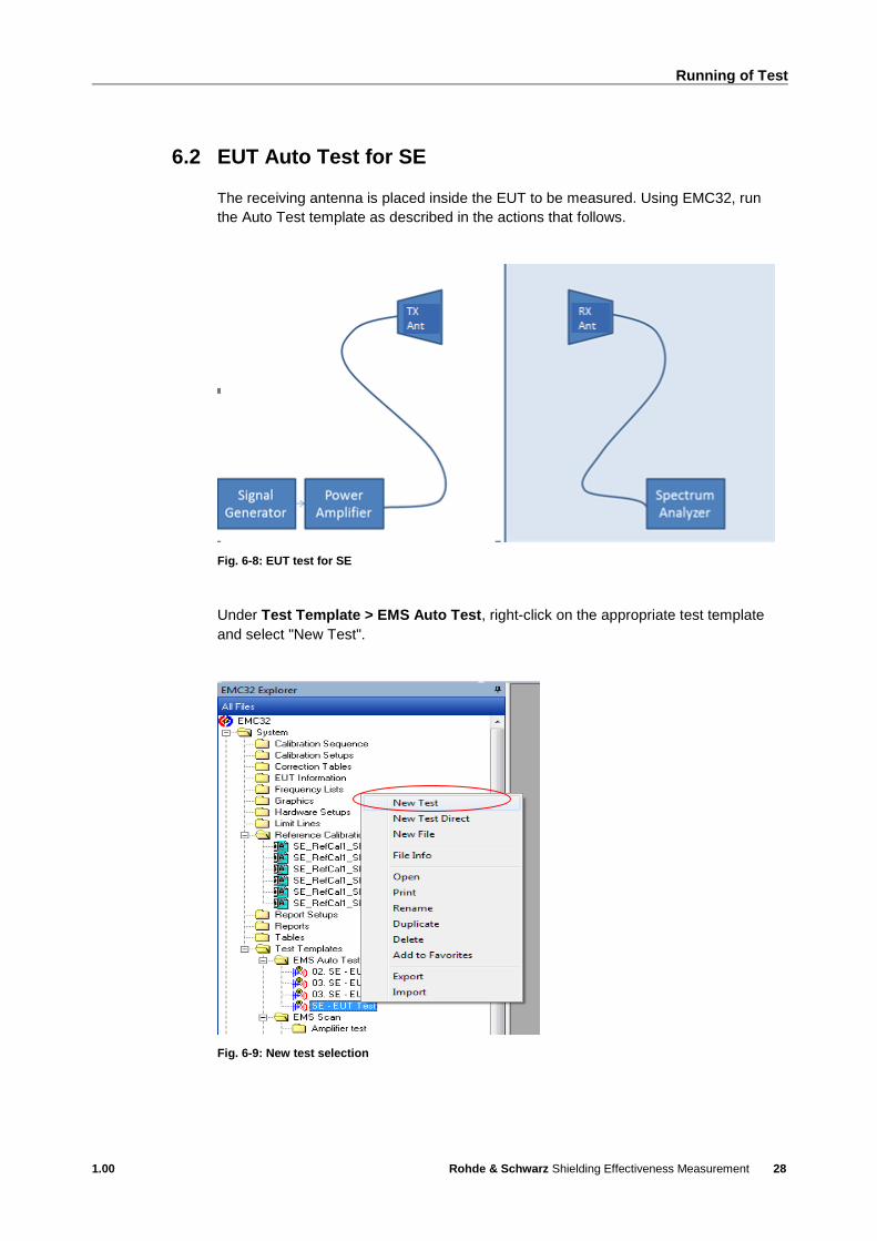
6.2 EUT Auto Test for SE
The receiving antenna is placed inside the EUT to be measured. Using EMC32, run
the Auto Test template as described in the actions that follows.
Fig. 6-8: EUT test for SE
Under Test Template > EMS Auto Test, right-click on the appropriate test template
and select "New Test".
Fig. 6-9: New test selection

Running of Test
1.00 Rohde & Schwarz Shielding Effectiveness Measurement
29
In Fig. 6-10, select Test Definition tab. Under Test method, select "EMS Auto Test"
from the dropdown list. Under EUT Monitoring Parameters, select the appropriate
EUT monitoring file and click OK.
Fig. 6-10: Test method selection
In Fig. 6-11, click play/start button to begin the EMS Auto Test for SE.
Fig. 6-11: EUT auto test

Running of Test
1.00 Rohde & Schwarz Shielding Effectiveness Measurement
30
In the left window toolbox under User Definition, right-click the corresponding set
position. Select Set as next Loop Position to move to the next frequency range or
polarization.
Fig. 6-12: Next loop position
The worst case analysis will be reflected when EUT Monitoring Template is used with
EMS Auto Test.
Fig. 6-13: Worst case analysis
Running of Test
1.00 Rohde & Schwarz Shielding Effectiveness Measurement
31
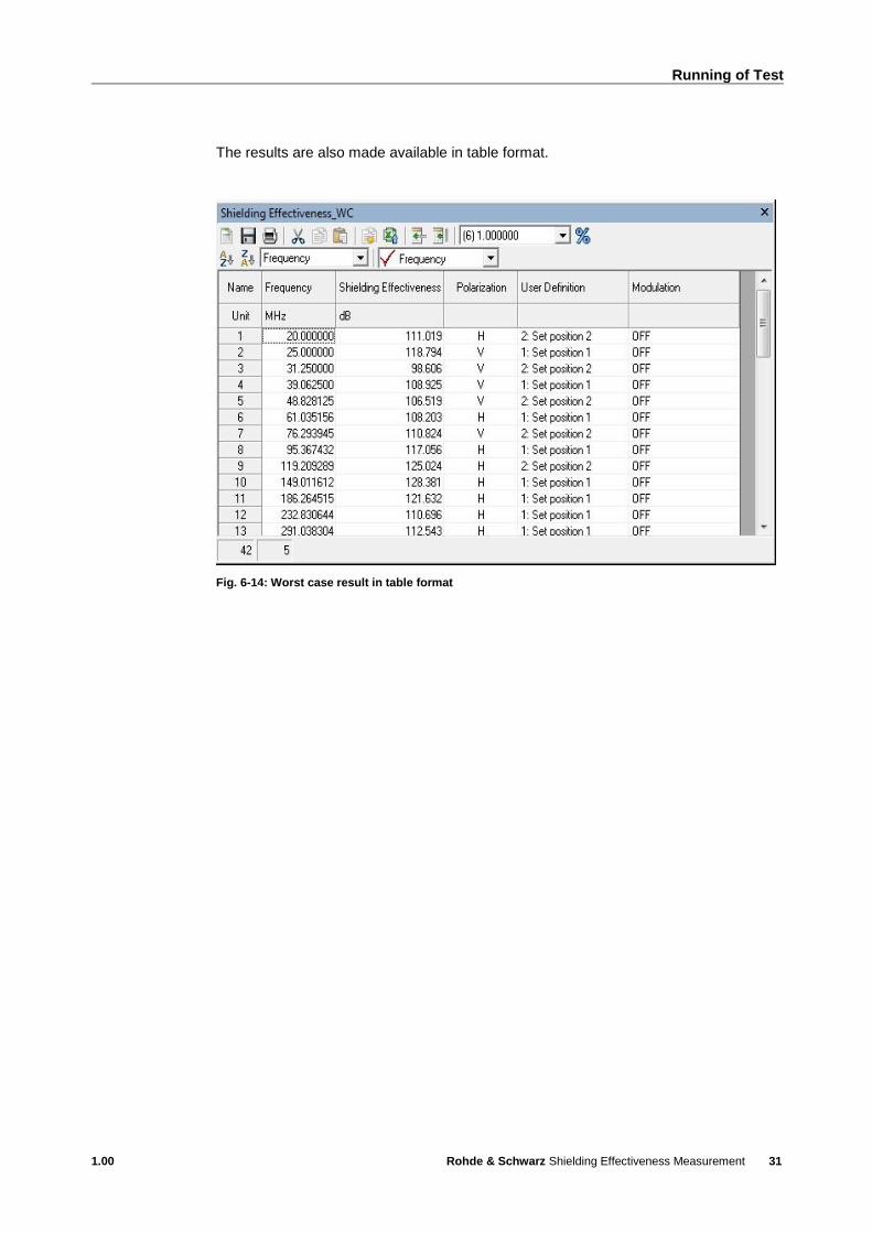
The results are also made available in table format.
Fig. 6-14: Worst case result in table format

Printing Report
1.00 Rohde & Schwarz Shielding Effectiveness Measurement
32
7 Printing Report
Refer to chapter 3.3 "Online Help" on page 6. In HTML Help, select the Index tab,
search for "Report" to show a detailed description on setting up the Report template
and print it out.
Fig. 7-1: Online help for report overview
7.1 Printing Report for SE
This section provides a guide to setting up and saving a report for SE.
When the test is complete, click on "Finish the Measurement" to exit
measurement mode.
Fig. 7-2: Measurement mode exit

Printing Report
1.00 Rohde & Schwarz Shielding Effectiveness Measurement
33
From the “Test Components” tab, right-click on the folder “Report Setups” and select
“Add Report Setup”.
Fig. 7-3: Report setup

Printing Report
1.00 Rohde & Schwarz Shielding Effectiveness Measurement
34
Select the appropriate report template and click OK
Fig. 7-4: Report template selection
The new setup will be shown in the folder "Report Setups" (see Fig. 7-5).
Fig. 7-5: Report setup creation

Printing Report
1.00 Rohde & Schwarz Shielding Effectiveness Measurement
35
From Fig. 7-6, double-click the designated report filename for more details.
Fig. 7-6: Report details

Printing Report
1.00 Rohde & Schwarz Shielding Effectiveness Measurement
36
In the left window toolbar under Selected Components (Fig. 7-6), double-click on
"Information" to enter the test report information description.
Fig. 7-7: Information details
In the left window toolbar under Selected Components (Fig. 7-6), double-click on
"Hardware Setup" to select the hardware setup required in the
report.
Fig. 7-8: Hardware setup option
Printing Report
1.00 Rohde & Schwarz Shielding Effectiveness Measurement
37
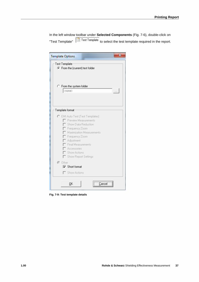
In the left window toolbar under Selected Components (Fig. 7-6), double-click on
"Test Template" to select the test template required in the report.
Fig. 7-9: Test template details

Printing Report
1.00 Rohde & Schwarz Shielding Effectiveness Measurement
38
In the left window toolbar under Selected Components (Fig. 7-6), double-click on
"Table" to select the type of tables required in the report.
Under Table Name, click on to select table types.
Fig. 7-10: Table selection
Printing Report
1.00 Rohde & Schwarz Shielding Effectiveness Measurement
39
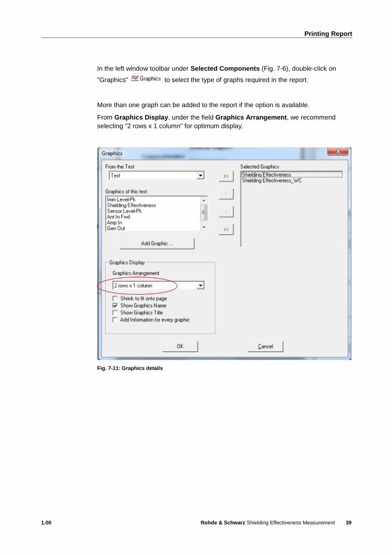
In the left window toolbar under Selected Components (Fig. 7-6), double-click on
"Graphics" to select the type of graphs required in the report.
More than one graph can be added to the report if the option is available.
From Graphics Display, under the field Graphics Arrangement, we recommend
selecting "2 rows x 1 column" for optimum display.
Fig. 7-11: Graphics details
Printing Report
1.00 Rohde & Schwarz Shielding Effectiveness Measurement
40
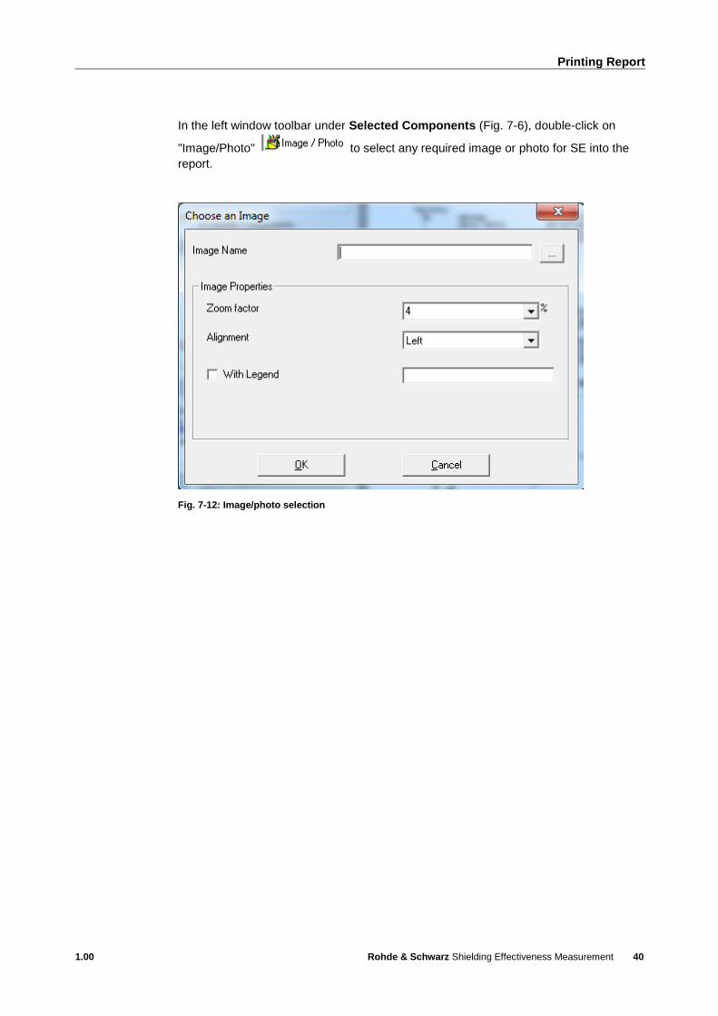
In the left window toolbar under Selected Components (Fig. 7-6), double-click on
"Image/Photo" to select any required image or photo for SE into the
report.
Fig. 7-12: Image/photo selection

Printing Report
1.00 Rohde & Schwarz Shielding Effectiveness Measurement
41
In the left window toolbar under Available Components (Fig. 7-6), click on "Export the
report" to export and save the final test report. Three types of file formats are
available: PDF, RTF and HTML.
Select ‘Save to the selected directory” and save the report to your desired file location.
Click OK to save the report.
Fig. 7-13: Saving of report

Printing Report
1.00 Rohde & Schwarz Shielding Effectiveness Measurement
42
Rohde & Schwarz
The Rohde & Schwarz electronics group offers
innovative solutions in the following business fields:
test and measurement, broadcast and media, secure
communications, cybersecurity, radiomonitoring and
radiolocation. Founded more than 80 years ago, this
independent company has an extensive sales and
service network and is present in more than 70
countries.
The electronics group is among the world market
leaders in its established business fields. The
company is headquartered in Munich, Germany. It
also has regional headquarters in Singapore and
Columbia, Maryland, USA, to manage its operations
in these regions.
Regional contact
Europe, Africa, Middle East +49 89 4129 12345 [email protected] North America 1 888 TEST RSA (1 888 837 87 72) [email protected] Latin America +1 410 910 79 88 [email protected] Asia Pacific +65 65 13 04 88 [email protected]
China +86 800 810 82 28 |+86 400 650 58 96 [email protected]
Sustainable product design
ı Environmental compatibility and eco-footprint
ı Energy efficiency and low emissions
ı Longevity and optimized total cost of ownership
This application note and the supplied programs
may only be used subject to the conditions of use
set forth in the download area of the Rohde &
Schwarz website.
R&S® is a registered trademark of Rohde & Schwarz GmbH & Co.
KG; Trade names are trademarks of the owners.
Rohde & Schwarz GmbH & Co. KG
Mühldorfstraße 15 | 81671 Munich, Germany
Phone + 49 89 4129 - 0 | Fax + 49 89 4129 – 13777
www.rohde-schwarz.com
PA
D-T
-M: 3573.7
380.0
2/0
2.0
4/E
N/