SHI CRYOCOOLER SPECIFICATION - TU Chemnitz · 2006-01-02 · SHI CRYOCOOLER SPECIFICATION MODEL:...
20
CD6505-010B December 16 / 2005 SHI CRYOCOOLER SPECIFICATION MODEL: SRDK-101E-A11C Cold Head Unit: RDK-101E Compressor Unit: CNA-11C Cryogenics Division Precision Equipment Group Sumitomo Heavy Industries, Ltd.
Transcript of SHI CRYOCOOLER SPECIFICATION - TU Chemnitz · 2006-01-02 · SHI CRYOCOOLER SPECIFICATION MODEL:...
CD6505-010BDecember 16 / 2005
SHI CRYOCOOLERSPECIFICATION
MODEL: SRDK-101E-A11C
Cold Head Unit: RDK-101ECompressor Unit: CNA-11C
Cryogenics DivisionPrecision Equipment Group
Sumitomo Heavy Industries, Ltd.

SHI CRYOCOOLERSPECIFICATION
MODEL: SRDK-101E-A11CCold Head Unit: RDK-101ECompressor Unit: CNA-11C
Cryogenics DepartmentSumitomo Heavy Industries, Ltd.
B 05 / 12 / 16 Outline Drawing revised. A. Hirato Y. Ikeya Y. IkeyaA 05 / 11 / 28 Original A. Hirato Y. Ikeya Y. Ikeya0
Rev. Date Description Prepared Checked Approved

CRYOCOOLER SPECIFICATION Cryocooler MODEL SRDK-101E-A11C
Cold Head Unit Model RDK-101ECompressor Unit Model CNA-11C
Regulation ULCE
New Condition
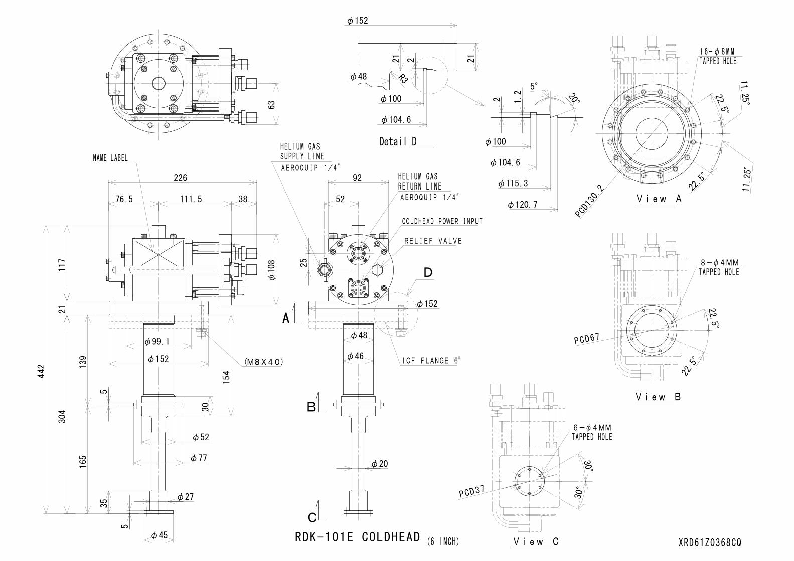
1. Cold Head Unit (Model: RDK-101E)
Refrigeration Cycle Modified Gifford-McMahon(2-Stage)
Site Condition Indoor
Cooling Capacity 1st 3.0 / 5.0 W at 60 K (50/60Hz) (Vertical Position) 2nd 0.1 W at 4.2 K (50/60Hz)
Lowest Temperature < 3.0 K -- for reference only
Cool Down Time < 150 min. -- for reference only(300K to 4.2K, 2nd Stage)
Cooling Capacity Degradation < 10 % -- for reference only(10,000Hrs.)
Orientation Free(Cooling Capacity Loss: max. 30%)
Ambient Temperature Range 5 to 35 deg.C(28 to 35 deg.C with cooling capacity loss max. 5%)

Dimension H: 442 x W: 152 x L: 226 mm -- approx.
Weight 7.2 kg -- approx.
Maintenance Shown in Table 1
Table 1 MAINTENANCE SCHEDULEFOR THE COLD HEAD UNIT
Maintenance Frequency Remark
Replace the Inside sliding parts Every 10,000 Hrs. “SHI maintenance”Return the Cold Head Unit to SHI, Ltd.
Notes・・・・The cooling capacity depends on the Flexible Gas Line length.・・・・The cooling capacity depends on the ambient temperature.・・・・The Heat Station plated with nickel plated with nickel is available upon the request.・・・・The room should be provided to install the Cold Head Unit.

2. Compressor Unit (Model: CNA-11C)
Cooling system Air Cooled
Site Condition Indoor
Electrical RequirementPower Line Voltage Single phase (2W+PE),
AC 100, 120, 220, 230, 240 V(+/- 10%)50 / 60 Hz
Power RequirementMinimum 1.8 kVARecommended 2.5 kVA
Power Consumption Steady Maximum50Hz 1.2 kW 1.3 kW -- approx.60Hz 1.3 kW 1.5 kW -- approx.
Operating CurrentMaximum 13 A -- approx.
Built-in Circuit Breaker Setting 16 A
Ambient Temperature Range 4 to 38 deg.C(28 to 38 deg.C with cooling capacity loss max. 5%)
Cooling Air Flow Rate50Hz 2.7 Nm3/min. -- approx.60Hz 3.3 Nm3/min. -- approx.
Heat Radiation to the Environment50Hz < 1.3 kW -- approx.60Hz < 1.5 kW -- approx.

Noise Level (1m distance)*Compressor Unit Only Max. 62 dBA -- approx.
*Noise level of the whole equipment may exceed 70dBA depending on the environment it is used in.
Dimension H: 610 x W: 385 x L: 450 mm* --approx.
* with Drive Unit and without Connectors.
Weight 75 kg -- approx.
Required Space* Refer to the ANNEX.*with air suction, discharge space and maintenance space.
Maintenance Shown in Table 2
Table 2 MAINTENANCE SCHEDULEFOR THE COMPRESSOR UNIT
Maintenance Frequency Remark
Replace the Adsorber Every 30,000 Hrs. “USER maintenance”
Charge/Purge the Helium Gas As required “USER maintenance”Purity of 99.999% up
Replace the Fuse(s) As required “USER maintenance”
Cleaning the Heat Exchanger As required “USER maintenance”Depending on the site conditions
Notes・・・・While carrying the compressor unit, do not tilt it by more than 30 degrees.・・・・While setting the compressor unit, do not tilt it by more than 5 degrees.

3. Accessories
Flexible Gas Line 10A x 3 m (F-F) (Supply) x 110A x 3 m (F-F) (Return) x 1
Cold Head Power Cable 6 m x 1
Input Power Cable 5 m x 1
Tool Kit Gas Charge Valve x 1Open end wrench (3/4 inch) x 2Open end wrench (5/8 inch) x 1
Manual Operation Manual x 1Technical Instruction x 1 for Cold Head UnitTechnical Instruction x 1 for Compressor Unit
Notes・・・・Longer Flexible Gas Lines and Cold Head Power Cable are available up to 6 m.・・・・Min. length is 3 m.

4. Annex.
1) System Configuration2) Cold Head Unit DWG.3) Compressor Unit DWG.4) Electrical Schematic.5) Required Space of Compressor Unit6) Flexible Gas Line DWG.7) Cold Head Power Cable DWG.8) Input Power Cable DWG.9) Gas Charge Valve DWG.10) Typical Refrigeration Capacity
5. Scope of Supply
The followings are included.1) Cold Head Unit2) Compressor Unit
(Include Transformer Unit, Drive Unit and Joint Cable)3) Input Power Cable4) Flexible Gas Lines (Supply and Return)5) Cold Head Power Cable6) Tool Kit7) Operation Manual
The followings are not included in this spec.1) Thermometer2) Temperature indicator3) O-ring between Cold Head Unit and Vacuum Chamber4) Vacuum Chamber5) Vacuum Pump6) Bolts

6. Warranty <Sale and Purchase of New Machines>
Warranty PeriodWarranty period for the newly supplied Machines shall be eighteen (18) months from the date of shipment of the Machinesfrom Sumitomo’s works or twelve (12) months from the date of the operation and use of the Machines by the customer,whichever comes earlier.
Warranty ConditionsDuring the warranty period, should any defects are found in the Machines irrespective of the fact that the Machines areproperly installed, connected and maintained in conformity to the instructions manuals and are properly operated under theconditions as instructed in the specifications and operation manuals, Sumitomo will, at its discretion, repair or replace free ofcharge the Machines except for the cases which fall under the category of the warranty exception as enumerated below.
Provided, however, that in the event the Machines are connected with the customer’s other equipment, the costs for theremoval from and re-installation of the Machines to such equipment, and other costs incidental to such work, includingtransportation charges thereto and so on shall be borne by the customer.
The scope of Sumitomo’s liability pursuant to the warranty shall be limited to the repair or replacement of the Machines.
Sumitomo shall not compensate any expenses, fees or charges for repair or replacement of the Machines or parts thereforincurred by the customer or third parties other than Sumitomo or Sumitomo’s authorized servicing companies without priorwritten consent of Sumitomo or Sumitomo’s authorized servicing companies.
SUMITOMO MAKES NO WARRANTIES OF MARCHANTABILITY OR FITNESS FOR ANY PARTICULAR USE ANDPURPOSE OF THE CUSTOMER, NOR ARE ANY OTHER WARRANTIES MADE, EXPRESS OR IMPLIED, UNLESSOTHERWISE SPECIFICALLY AGREED IN WRITING.
Warranty ExceptionThe warranty shall not apply to the following cases.
1. Any defects caused by improper installation of the Machines or improper connection with other related equipment bythe customer or third party other than Sumitomo or Sumitomo’s authorized servicing companies.
2. Any defects caused by insufficient maintenance or improper handling of the Machines by the customers.3. Any defects caused by the operation of the Machines outside the specifications or operation and use conditions
beyond Sumitomo’s expectation by the customer.4. Any defects caused by the modification or alteration to the Machines by the customer or third parties other than
Sumitomo or Sumitomo’s authorized servicing companies.5. Any defects of the Machines caused by the parts supplied or specified by the customer.6. Any damage caused by Force Majeure, such as earthquakes, fires, floods, salt damage, gas damage, thunder and
other causes beyond the control of Sumitomo.7. Any other defects caused by the events not attributable to Sumitomo.
Limitation of DamagesAny damages, if any, to be compensated to the customer due to the defects of the Machines attributable to Sumitomo shallbe limited to the direct damages actually incurred by the customer and shall not exceed the contract price of the Machines.
IndemnificationSumitomo shall not be responsible for the following damage irrespective of the causes or reasons for the claims made by thecustomer.
1. Any losses of profits and operation opportunity and other consequential or indirect loss or damage of any kindincurred by the customer in connection with the Machines.
2. Any damage to the Machines caused by any special circumstance on the part of the customer which is attributable tothe customer irrespective of whether such damage is foreseeable or not by Sumitomo.
3. Any damage incurred by the customer resulting from the damages claimed by third party for which Sumitomo is notresponsible.
4. Any damage incurred by the customer due to collection and improvement of the same kind of machines or similar tothe Machines caused by recall of those machines.
MaintenanceThe maintenance work of the Machines shall be recommendable to be performed at an interval which is described in theabove sentence.
Parts SupplyUnless otherwise specified in the contract documents, Sumitomo shall keep any parts for the Machines for a period of seven(7) years from the delivery date of the Machines to the customer.
Notes; Specifications subject to change or delete without notice.

SYSTEM CONFIGURATION

COMPRESSOR UNIT

ELECTRICAL SCHEMATIC(TRANSFORMER UNIT)
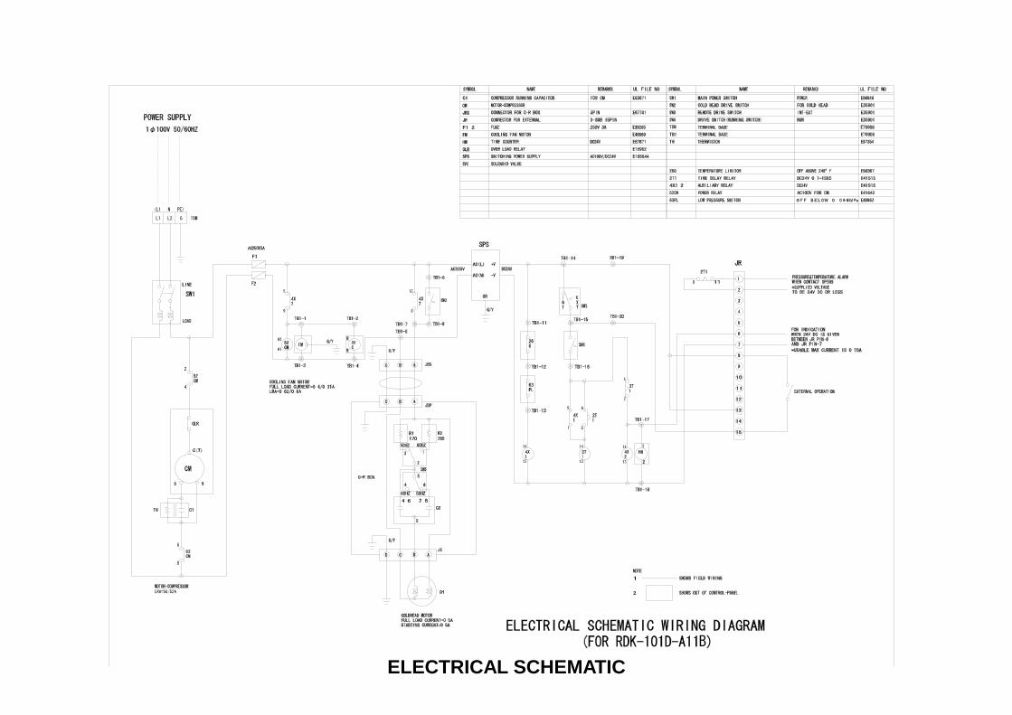
ELECTRICAL SCHEMATIC

REQUIRED SPACE OF COMPRESSOR UNIT

10A x 3m (F-F) FLEXIBLE GAS LINE
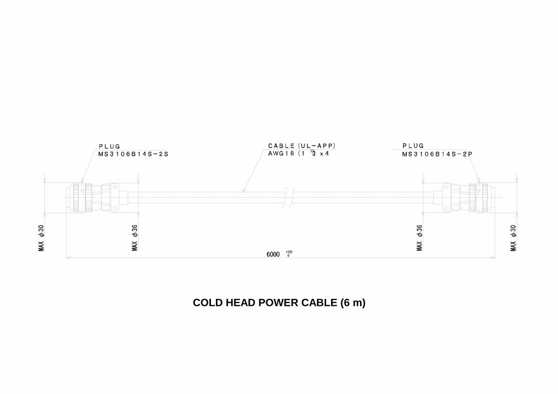
COLD HEAD POWER CABLE (6 m)

INPUT POWER CABLE (5 m)

GAS CHARGE VALVE

TYPICAL REFRIGERATION CAPACITY
RDK101D Typical Load Map (50Hz)
0
4
8
12
16
20
25 30 35 40 45 50 55 60 65 701st Stage Temperature (K)
2nd
Sta
ge T
empe
ratu
re (K
)
0W 1W 2W 3W4W
0.1W
0.2W
0.3W
0.5W
1.0W
1.5W
2.0W
1st Stage Heat Load (Watts)
2nd
Stag
e H
eat L
oad
(Wat
ts)
RDK101D Typical Load Map (60Hz)
0
4
8
12
16
20
25 30 35 40 45 50 55 60 65 701st Stage Temperature (K)
2nd
Sta
ge T
empe
ratu
re (K
)
0W 1W2W 3W 4W
0.1W
0.2W
0.3W
0.5W
1.0W
1.5W
2.0W
5W
2.5W
1st Stage Heat Load (Watts)
2nd
Stag
e H
eat L
oad
(Wat
ts)