
Shear Strength of Soil-final
94
Shear Strength of Soils
-
Upload
arun-rajagopal -
Category
Documents
-
view
236 -
download
9
description
shear strength of soil notes
Transcript of Shear Strength of Soil-final

Shear Strength of Soils
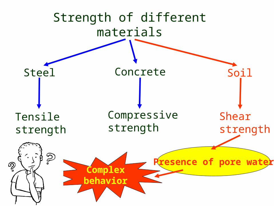
Strength of different materials
Steel
Tensile strength
Concrete
Compressive strength
Soil
Shear strength
Presence of pore waterComplexbehavior

Embankment
Strip footing
Shear failure of soilsSoils generally fail in shear
At failure, shear stress along the failure surface (mobilized shear resistance) reaches the shear strength.
Failure surface
Mobilized shear resistance

Retaining wall
Shear failure of soilsSoils generally fail in shear

Retaining wall
Shear failure of soils
At failure, shear stress along the failure surface (mobilized shear resistance) reaches the shear strength.
Failure surface
Mobilized shear resistance
Soils generally fail in shear

Shear failure mechanism
The soil grains slide over each other along the failure surface.No crushing of individual grains.
failure surface

Shear failure mechanism
At failure, shear stress along the failure surface () reaches the shear strength (f).

Mohr-Coulomb Failure Criterion(in terms of total stresses)
f is the maximum shear stress the soil can take without failure, under normal stress of .
tancf
c
failure envelope
Cohesion
Friction anglef

Mohr-Coulomb Failure Criterion(in terms of effective stresses)
f is the maximum shear stress the soil can take without failure, under normal effective stress of ’.
’
'tan'' cf
c’
’
failure envelope
Effective
cohesion
Effectivefriction angle
f
’
u '
u = pore water pressure

Mohr-Coulomb Failure Criterion
'tan'' ff c
Shear strength consists of two components: cohesive and frictional.
’f
f
’
'
c’ c’cohesive
component
’f tan ’ frictional component

c and are measures of shear strength.
Higher the values, higher the shear strength.

Mohr Circle of stress
Soil element
’1
’1
’3’3
’
222
22
'3
'1
'3
'1'
'3
'1
Cos
Sin
Resolving forces in and directions,
2'3
'
1
2'3
'1'2
22

Mohr Circle of stress
2'3
'
1
2'3
'1'2
22
Soil element
’1
’1
’3’3
’
Soil elementSoil element
’1
’1
’3’3
’1
’1
’3’3
’
’
’
2
'3
'1
2
'3
'1
'3
'1

Mohr Circle of stress
2'3
'
1
2'3
'1'2
22
Soil element
’1
’1
’3’3
’
Soil elementSoil element
’1
’1
’3’3
’1
’1
’3’3
’
’
’
2
'3
'1
2
'3
'1
'3
'1
PD = Pole w.r.t. plane
’,

Soil elements at different locations
Failure surface
Mohr Circles & Failure Envelope
X X
X ~ failure
YY
Y ~ stable
’
'tan'' cf

Mohr Circles & Failure Envelope
Y
c
c
c
Initially, Mohr circle is a point
c+
The soil element does not fail if the Mohr circle is contained within the envelope
GL

Mohr Circles & Failure Envelope
Y
c
c
c
GL
As loading progresses, Mohr circle becomes larger…
.. and finally failure occurs when Mohr circle touches the envelope

’
2
'3
'1 '
3'1
PD = Pole w.r.t. plane
’, f
Orientation of Failure Plane
’
’1
’1
’3’3
’
’1
’1
’3’3
’
Failure envelope
–
Therefore,
–’ = 45 + ’/2

Mohr circles in terms of total & effective stresses
= X
v’
h’ X
u
u+
v’h’
effective stresses
uvh
X
v
h
total stresses
or’

Failure envelopes in terms of total & effective stresses
= X
v’
h’ X
u
u+
v’h’
effective stresses
uvh
X
v
h
total stresses
or’
If X is on failure
c
Failure envelope in terms of total stresses
’
c’
Failure envelope in terms of effective stresses

Mohr Coulomb failure criterion with Mohr circle of stress
X
’v = ’1
’h = ’3
X is on failure ’1’3
effective stresses
’’ c’
Failure envelope in terms of effective stresses
c’ Cot’ ’’
’’
2'
2''
'3
'1
'3
'1 SinCotc
Therefore,

Mohr Coulomb failure criterion with Mohr circle of stress
2'
2''
'3
'1
'3
'1 SinCotc
''2''3
'1
'3
'1 CoscSin
''2'1'1 '3
'1 CoscSinSin
'1
''2
'1
'1'3
'1
Sin
Cosc
Sin
Sin
2
'45'2
2
'452'
3'1
TancTan

Other laboratory tests include,Direct simple shear test, torsional ring shear test, plane strain triaxial test, laboratory vane shear test, laboratory fall cone test
Determination of shear strength parameters of soils (c, orc’’
Laboratory tests on specimens taken from representative undisturbed samples
Field tests
Most common laboratory tests to determine the shear strength parameters are,
1.Direct shear test2.Triaxial shear test
1. Vane shear test2. Torvane3. Pocket penetrometer4. Fall cone5. Pressuremeter6. Static cone penetrometer7. Standard penetration test

Laboratory tests
Field conditions
z vc
vc
hchc
Before construction
A representative soil sample
z vc +
hchc
After and during construction
vc +

Laboratory testsSimulating field conditions in the laboratory
Step 1
Set the specimen in the apparatus and apply the initial stress condition
vc
vc
hchc
Representative soil sample taken from the site
0
00
0
Step 2
Apply the corresponding field stress conditions
vc +
hchc
vc + Traxial t
est
vc
vc
Direct shear test

Direct shear testSchematic diagram of the direct shear apparatus

Direct shear test
Preparation of a sand specimen
Components of the shear box Preparation of a sand specimen
Porous plates
Direct shear test is most suitable for consolidated drained tests specially on granular soils (e.g.: sand) or stiff clays

Direct shear test
Leveling the top surface of specimen
Preparation of a sand specimen
Specimen preparation completed
Pressure plate

Direct shear test
Test procedure
Porous plates
Pressure plate
Steel ball
Step 1: Apply a vertical load to the specimen and wait for consolidation
P
Proving ring to measure shear force
S

Direct shear test
Step 2: Lower box is subjected to a horizontal displacement at a constant rate
Step 1: Apply a vertical load to the specimen and wait for consolidation
PTest procedure
Pressure plate
Steel ball
Proving ring to measure shear force
S
Porous plates

Direct shear test
Shear box
Loading frame to apply vertical load
Dial gauge to measure vertical displacement
Dial gauge to measure horizontal displacement
Proving ring to measure shear force

Direct shear testAnalysis of test results
sample theofsection cross of Area
(P) force Normal stress Normal
sample theofsection cross of Area
(S) surface sliding at the developed resistanceShear stressShear
Note: Cross-sectional area of the sample changes with the horizontal displacement

Direct shear tests on sands
Sh
ear
str
ess
,
Shear displacement
Dense sand/ OC clayfLoose sand/ NC clayf
Dense sand/OC Clay
Loose sand/NC Clay
Ch
ang
e in
hei
gh
t o
f th
e sa
mp
le Exp
ansi
on
Co
mp
ress
ion Shear displacement
Stress-strain relationship

f1
Normal stress = 1
Direct shear tests on sandsHow to determine strength parameters c and
Sh
ear
stre
ss,
Shear displacement
f2
Normal stress = 2
f3
Normal stress = 3
Sh
ear
stre
ss a
t fa
ilu
re,
f
Normal stress,
Mohr – Coulomb failure envelope

Direct shear tests on sandsSome important facts on strength parameters c and of sand
Sand is cohesionless hence c = 0
Direct shear tests are drained and pore water pressures are dissipated, hence u = 0
Therefore,
’ = and c’ = c = 0

Direct shear tests on clays
Failure envelopes for clay from drained direct shear tests
Sh
ear
stre
ss a
t fa
ilu
re,
f
Normal force,
’
Normally consolidated clay (c’ = 0)
In case of clay, horizontal displacement should be applied at a very slow rate to allow dissipation of pore water pressure (therefore, one test would take several days to finish)
Overconsolidated clay (c’ ≠ 0)

Interface tests on direct shear apparatusIn many foundation design problems and retaining wall problems, it is required to determine the angle of internal friction between soil and the structural material (concrete, steel or wood)
tan' af c Where,
ca = adhesion,
= angle of internal friction
Foundation material
Soil
P
S
Foundation material
Soil
P
S

Triaxial Shear Test
Soil sample at failure
Failure plane
Porous stone
impervious membrane
Piston (to apply deviatoric stress)
O-ring
pedestal
Perspex cell
Cell pressureBack pressure Pore pressure or
volume change
Water
Soil sample

Triaxial Shear TestSpecimen preparation (undisturbed sample)
Sampling tubes
Sample extruder

Triaxial Shear TestSpecimen preparation (undisturbed sample)
Edges of the sample are carefully trimmed
Setting up the sample in the triaxial cell

Triaxial Shear Test
Sample is covered with a rubber membrane and sealed
Cell is completely filled with water
Specimen preparation (undisturbed sample)

Triaxial Shear TestSpecimen preparation (undisturbed sample)
Proving ring to measure the deviator load
Dial gauge to measure vertical displacement

Types of Triaxial Tests
Is the drainage valve open?
yes no
Consolidated sample
Unconsolidated sample
Is the drainage valve open?
yes no
Drained loading
Undrained loading
Under all-around cell pressure c
cc
c
cStep 1
deviatoric stress ( = q)
Shearing (loading)
Step 2
c c
c+ q

Types of Triaxial Tests
Is the drainage valve open?
yes no
Consolidated sample
Unconsolidated sample
Under all-around cell pressure c
Step 1
Is the drainage valve open?
yes no
Drained loading
Undrained loading
Shearing (loading)
Step 2
CD test
CU test
UU test

Consolidated- drained test (CD Test)
Step 1: At the end of consolidationVC
hC
Total, = Neutral, u Effective, ’+
0
Step 2: During axial stress increase
’VC = VC
’hC = hC
VC +
hC 0
’V = VC +
=’1
’h = hC =’3
Drainage
Drainage
Step 3: At failureVC + f
hC 0
’Vf = VC + f=’1f
’hf = hC =’3fDrainage

Deviator stress (q or d) = 1 – 3
Consolidated- drained test (CD Test)
1 = VC +
3 = hC

Vo
lum
e ch
ang
e o
f th
e sa
mp
le
Exp
ansi
on
Co
mp
ress
ion
Time
Volume change of sample during consolidation
Consolidated- drained test (CD Test)

De
via
tor
str
ess
,
d
Axial strain
Dense sand or OC clay
d)f
Dense sand or OC clay
Loose sand or NC clay
Vo
lum
e ch
ang
e o
f th
e sa
mp
le Exp
ansi
on
Co
mp
ress
ion Axial strain
Stress-strain relationship during shearing
Consolidated- drained test (CD Test)
Loose sand or NC Clayd)f

CD tests How to determine strength parameters c and D
evia
tor
stre
ss,
d
Axial strain
Sh
ear
stre
ss,
or’
Mohr – Coulomb failure envelope
d)fa
Confining stress = 3ad)fb
Confining stress = 3b
d)fc
Confining stress = 3c
3c 1c3a 1a
(d)fa
3b 1b
(d)fb
1 = 3 + (d)f
3

CD tests
Strength parameters c and obtained from CD tests
Since u = 0 in CD tests, = ’
Therefore, c = c’ and = ’
cd and d are used to denote them

CD tests Failure envelopesS
hea
r st
ress
,
or’
d
Mohr – Coulomb failure envelope
3a 1a
(d)fa
For sand and NC Clay, cd = 0
Therefore, one CD test would be sufficient to determine d
of sand or NC clay

CD tests Failure envelopes
For OC Clay, cd ≠ 0
or’
3 1
(d)f
cc
OC NC

Some practical applications of CD analysis for clays
= in situ drained shear strength
Soft clay
1. Embankment constructed very slowly, in layers over a soft clay deposit

Some practical applications of CD analysis for clays
2. Earth dam with steady state seepage
= drained shear strength of clay core
Core

Some practical applications of CD analysis for clays
3. Excavation or natural slope in clay
= In situ drained shear strength
Note: CD test simulates the long term condition in the field. Thus, cd and d should be used to evaluate the long term behavior of soils

Consolidated- Undrained test (CU Test)
Step 1: At the end of consolidationVC
hC
Total, = Neutral, u Effective, ’+
0
Step 2: During axial stress increase
’VC = VC
’hC = hC
VC +
hC ±u
Drainage
Step 3: At failureVC + f
hC
No drainage
No drainage ±uf
’V = VC + ±u =’1
’h = hC ±u
=’3
’Vf = VC + f±uf =’1f
’hf = hC ±uf =’3f

Vo
lum
e ch
ang
e o
f th
e sa
mp
le
Exp
ansi
on
Co
mp
ress
ion
Time
Volume change of sample during consolidation
Consolidated- Undrained test (CU Test)

De
via
tor
str
ess
,
d
Axial strain
Dense sand or OC clay
d)f
Dense sand or OC clay
Loose sand /NC Clayu
+-
Axial strain
Stress-strain relationship during shearing
Consolidated- Undrained test (CU Test)
Loose sand or NC Clayd)f

CU tests How to determine strength parameters c and D
evia
tor
stre
ss,
d
Axial strain
Sh
ear
stre
ss,
or’
d)fb
Confining stress = 3b
3b 1b3a 1a
(d)fa
cuMohr – Coulomb failure envelope in terms of total stresses
ccu
1 = 3 + (d)f
3
Total stresses at failured)fa
Confining stress = 3a

(d)fa
CU tests How to determine strength parameters c and S
hea
r st
ress
,
or’3b 1b3a 1a
(d)fa
cu
Mohr – Coulomb failure envelope in terms of total stresses
ccu’3b ’1b
’3a ’1a
Mohr – Coulomb failure envelope in terms of effective stresses
’
C’ ufa
ufb
’1 = 3 + (d)f -
uf
’=3 -
ufEffective stresses at failure
uf

CU tests
Strength parameters c and obtained from CD tests
Shear strength parameters in terms of total stresses are ccu and cu
Shear strength parameters in terms of effective stresses are c’ and ’
c’ = cd and ’ = d

CU tests Failure envelopes
For sand and NC Clay, ccu and c’ = 0
Therefore, one CU test would be sufficient to determine cu and ’= d) of sand or NC clay
Sh
ear
stre
ss,
or’
cuMohr – Coulomb failure envelope in terms of total stresses
3a 1a
(d)fa
3a 1a
’
Mohr – Coulomb failure envelope in terms of effective stresses
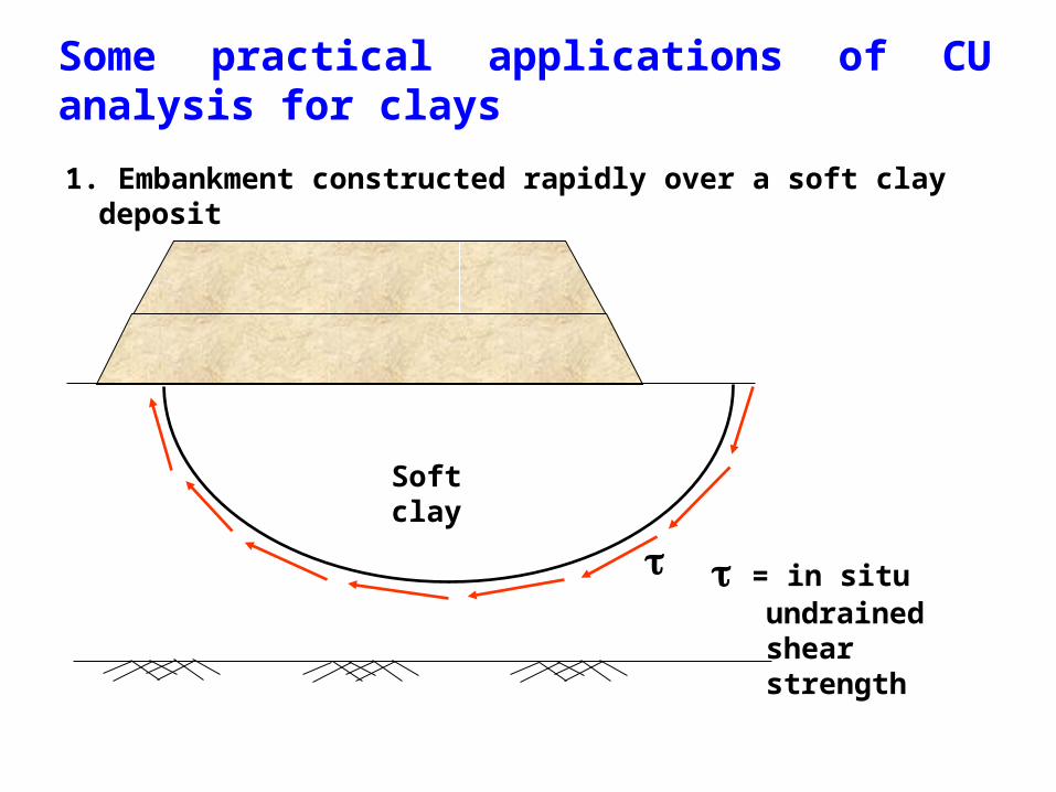
Some practical applications of CU analysis for clays
= in situ undrained shear strength
Soft clay
1. Embankment constructed rapidly over a soft clay deposit

Some practical applications of CU analysis for clays
2. Rapid drawdown behind an earth dam
= Undrained shear strength of clay core
Core

Some practical applications of CU analysis for clays
3. Rapid construction of an embankment on a natural slope
Note: Total stress parameters from CU test (ccu and cu) can be used for stability problems where,
Soil have become fully consolidated and are at equilibrium with the existing stress state; Then for some reason additional stresses are applied quickly with no drainage occurring
= In situ undrained shear strength

Unconsolidated- Undrained test (UU Test)Data analysis
C = 3
C = 3
No drainage
Initial specimen condition
3 + d
3
No drainage
Specimen condition during shearing
Initial volume of the sample = A0 × H0
Volume of the sample during shearing = A × H
Since the test is conducted under undrained condition,
A × H = A0 × H0
A ×(H0 – H) = A0 × H0
A ×(1 – H/H0) = A0z
AA
10

Unconsolidated- Undrained test (UU Test)
Step 1: Immediately after sampling0
0
= +
Step 2: After application of hydrostatic cell pressure
uc = B 3
C = 3
C = 3 uc
’3 = 3 -uc
’3 = 3 -uc
No drainage
Increase of pwp due to increase of cell pressure
Increase of cell pressure
Skempton’s pore water pressure parameter, B
Note: If soil is fully saturated, then B = 1 (hence, uc = 3)

Unconsolidated- Undrained test (UU Test)
Step 3: During application of axial load
3 + d
3
No drainage
’1 = 3 + d- uc ud
’3 = 3 - uc ud
ud = ABd
uc ± ud
= +
Increase of pwp due to increase of deviator stress
Increase of deviator stress
Skempton’s pore water pressure parameter, A

Unconsolidated- Undrained test (UU Test)
Combining steps 2 and 3,
uc = B 3 ud = ABd
u = uc + ud
Total pore water pressure increment at any stage, u
u = B [3 + Ad]
Skempton’s pore water pressure equation
u = B [3 + A(1 – 3]

Unconsolidated- Undrained test (UU Test)
Step 1: Immediately after sampling
0
0
Total, = Neutral, u Effective, ’+
-ur
Step 2: After application of hydrostatic cell pressure
’V0 = ur
’h0 = ur
C
C
-uruc = -urc
(Sr = 100% ; B = 1)Step 3: During application of axial load
C +
C
No drainage
No drainage
-urc ± u
’VC = C +ur - C=ur
’h = ur
Step 3: At failure
’V = C + + ur - c u
’h = C + ur - c u
’hf = C + ur - c uf
= ’3f
’Vf = C + f+ ur - c uf = ’1f
-urc ± ufC
C + fNo drainage

Unconsolidated- Undrained test (UU Test)
Total, = Neutral, u Effective, ’+Step 3: At failure
’hf = C + ur - c uf
= ’3f
’Vf = C + f+ ur - c uf = ’1f
-urc ± ufC
C + fNo drainage
Mohr circle in terms of effective stresses do not depend on the cell pressure.
Therefore, we get only one Mohr circle in terms of effective stress for different cell pressures
’’3 ’1f

3b 1b3a 1af’3 ’1
Unconsolidated- Undrained test (UU Test)
Total, = Neutral, u Effective, ’+Step 3: At failure
’hf = C + ur - c uf
= ’3f
’Vf = C + f+ ur - c uf = ’1f
-urc ± ufC
C + fNo drainage
or ’
Mohr circles in terms of total stresses
uaub
Failure envelope, u = 0
cu

3b b
Unconsolidated- Undrained test (UU Test)
Effect of degree of saturation on failure envelope
3a a3c c
or ’
S < 100% S > 100%

Some practical applications of UU analysis for clays
= in situ undrained shear strength
Soft clay
1. Embankment constructed rapidly over a soft clay deposit

Some practical applications of UU analysis for clays
2. Large earth dam constructed rapidly with no change in water content of soft clay
Core
= Undrained shear strength of clay core

Some practical applications of UU analysis for clays
3. Footing placed rapidly on clay deposit
= In situ undrained shear strength
Note: UU test simulates the short term condition in the field. Thus, cu can be used to analyze the short term behavior of soils

Unconfined Compression Test (UC Test)
1 = VC +
3 = 0
Confining pressure is zero in the UC test

Unconfined Compression Test (UC Test)
1 = VC + f
3 = 0
Sh
ear
stre
ss,
Normal stress,
qu
τf = σ1/2 = qu/2 = cu
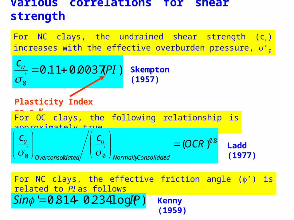
Various correlations for shear strength
For NC clays, the undrained shear strength (cu) increases with the effective overburden pressure, ’0
)(0037.011.0'0
PIcu
Skempton (1957)
Plasticity Index as a %
For OC clays, the following relationship is approximately true
8.0
'0
'0
)(OCRcc
edConsolidatNormally
u
idatedOverconsol
u
Ladd (1977)
For NC clays, the effective friction angle (’) is related to PI as follows
)log(234.0814.0' IPSin Kenny (1959)

Shear strength of partially saturated soils
In the previous sections, we were discussing the shear strength of saturated soils. However, in most of the cases, we will encounter unsaturated soils
Solid
Water
Saturated soils
Pore water pressure, u
Effective stress, ’
Solid
Unsaturated soils
Pore water pressure, uw
Effective stress, ’
Water
Air Pore air pressure, ua
Pore water pressure can be negative in unsaturated soils

Shear strength of partially saturated soils
Bishop (1959) proposed shear strength equation for unsaturated soils as follows
'tan)()(' waanf uuuc Where,
n – ua = Net normal stress
ua – uw = Matric suction= a parameter depending on the degree of saturation
( = 1 for fully saturated soils and 0 for dry soils)
Fredlund et al (1978) modified the above relationship as follows
bwaanf uuuc tan)('tan)('
Where,
tanb = Rate of increase of shear strength with matric suction

Shear strength of partially saturated soils
bwaanf uuuc tan)('tan)('
Same as saturated soils Apparent cohesion due to matric suction
Therefore, strength of unsaturated soils is much higher than the strength of saturated soils due to matric suction
-ua
’ua
– uw = 0(ua
– uw)1
> 0(ua – uw
)2 > (ua
– uw)1

-ua
How it become possible build a sand castle
bwaanf uuuc tan)('tan)('
Same as saturated soils Apparent cohesion due to matric suction
’
ua – uw
= 0 Failure envelope for saturated sand (c’ = 0)
(ua – uw
) > 0 Failure envelope for unsaturated sand
Apparent cohesion

• What does Vane Shear Test measure?
o Shear strength a term used to describe the maximum strength of soil at which point
significant plastic deformation or yielding occurs due to an applied shear stress.
o Undrained shear strength refers to a shear condition where water does not enter or leave the
cohesive soil during the shearing processo Remolded undrained shear strength
is the peak undrained shearing resistance measured during the initial rotation of the vane.
o Peak undrained shear strength is the shear strength after significant failure and remolding of the initial
soil structure.o Sensitivity
is the effect of remolding on the consistency of cohesive soil.
Vane shear test

PLAN VIEW
Vane shear test
This is one of the most versatile and widely used devices used for investigating undrained shear strength (Cu) and sensitivity of soft clays
Bore hole (diameter = DB)
h > 3DB)
Vane
D
H
Applied Torque, T
Vane T
Rupture surface
Disturbed soil
Rate of rotation : 60 – 120 per minute
Test can be conducted at 0.5 m vertical intervals

Vane shear test
Since the test is very fast, Unconsolidated Undrained (UU) can be expected
Cu
Cu
T = Ms + Me + Me = Ms + 2Me
Me – Assuming a uniform distribution of shear strength
2
0
).2(
d
ue rCrdrM
2
0
32
0
2
322
d
u
d
ue
rCdrrCM
1283
2 33 dCdCM uu
e
d/2d/2
Cu
h

Surface area of the cylinder = 2rh= dh

Vane shear test
Since the test is very fast, Unconsolidated Undrained (UU) can be expected
Cu
Cu
Ms – Shaft shear resistance along the circumference
22
2hdC
ddhCM uus
2122
32
dChd
CT uu
62
32 dhdCT u
62
32 dhd
TCu
T = Ms + Me + Me = Ms + 2Me

Vane shear test
Since the test is very fast, Unconsolidated Undrained (UU) can be expected
Cu
Cu
T = Ms + Me + Me = Ms + 2Me
Me – Assuming a triangular distribution of shear strength
h
d/2d/2
Cu
82
32 dhd
TCu
Can you derive this ???

Vane shear test
Since the test is very fast, Unconsolidated Undrained (UU) can be expected
Cu
Cu
T = Ms + Me + Me = Ms + 2Me
Me – Assuming a parabolic distribution of shear strength
h
203
2
32 dhd
TCu
Can you derive this ???
d/2d/2
Cu

Vane shear test
Since the test is very fast, Unconsolidated Undrained (UU) can be expected
Cu
Cu
h
After the initial test, vane can be rapidly rotated through several revolutions until the clay become remoulded
peak ultimate
Shear displacement
StengthUltimate
StengthPeakySensitivit

Some important facts on vane shear test
Insertion of vane into soft clays and silts disrupts the natural soil structure around the vane causing reduction of shear strength
The above reduction is partially regained after some time
Cu as determined by vane shear test may be a function of the rate of angular rotation of the vane

Correction for the strength parameters obtained from vane shear test
Bjerrum (1974) has shown that as the plasticity of soils increases, Cu obtained by vane shear tests may give unsafe results for foundation design. Therefore, he proposed the following correction.
Cu(design) = Cu(vane shear)
Where, = correction factor = 1.7 – 0.54 log (PI)
PI = Plasticity Index


