SHEAR PERFORMANCE OF FIBER REINFORCED SELF COMPACTING CONCRETE DEEP BEAMS
22
http://www.iaeme.com/IJCIET/index.asp 25 [email protected] International Journal of Civil Engineering and Technology (IJCIET) Volume 7, Issue 1, Jan-Feb 2016, pp. 25-46, Article ID: IJCIET_07_01_003 Available online at http://www.iaeme.com/IJCIET/issues.asp?JType=IJCIET&VType=7&IType=1 Journal Impact Factor (2016): 9.7820 (Calculated by GISI) www.jifactor.com ISSN Print: 0976-6308 and ISSN Online: 0976-6316 © IAEME Publication SHEAR PERFORMANCE OF FIBER REINFORCED SELF COMPACTING CONCRETE DEEP BEAMS Maher A. Adam Associate Prof., Civil Eng. Dept, Shoubra Faculty of Eng., Benha University, Egypt Mohamed Said Assistant Prof., Civil Eng. Dept, Shoubra Faculty of Eng, Benha University, Egypt Tamer. M. Elrakib Associate Prof, Housing and Building National Research Center, Giza, Egypt ABSTRACT The self-compacting concrete (SCC) is the newest innovating category of high performance concrete. The shear behavior of Fiber Reinforced Self- Compacted Concrete (FRSCC) deep beams was investigated. The experimental program consisted of twelve simply supported beams tested up to failure under four-point load. The key parameters covered in this investigation were steel fibers ratios (0.0, 0.50, 0.75 & 1.00%) and the effective shear span to depth ratio; a/d that varied from 0.6 to 1.0. Also, the main flexure reinforcement ratio was variable (1.0, 1.60 and 2.20 percent). In addition, vertical and horizontal web reinforcement effect was investigated. The mid- span deflection, cracks, reinforcement and concrete strains of the tested beams were recorded and compared. Test results pointed out that the steel fibers enhanced the cracking load, ultimate capacity, displacement and energy absorption of the tested FRSCC deep beams. The utmost enhancement in the performance of deep beams was achieved with steel fibers content of 1.0% within the range of the test parameters. The enhancement in the ultimate capacity was 40%. The test results indicated that both vertical and horizontal web reinforcement are efficient in shear capacity enhancement of FRSCC deep beams. The ultimate shear capacity was increased by about 47% with increasing the longitudinal steel ratio from 1.0% to 2.2%. Maximum strain in the extreme compression fiber of concrete section was 0.0019 and achieved at specimen tested at a/d ratio of 0.6. A non-linear finite element analysis (NLFEA) model was constructed to simulate the shear behavior of tested beams, in terms of crack pattern and load deflection behavior. It can be concluded that a good agreement between the experimental and numerical
-
Upload
iaeme-publication -
Category
Engineering
-
view
288 -
download
0
Transcript of SHEAR PERFORMANCE OF FIBER REINFORCED SELF COMPACTING CONCRETE DEEP BEAMS

http://www.iaeme.com/IJCIET/index.asp 25 [email protected]
International Journal of Civil Engineering and Technology (IJCIET)
Volume 7, Issue 1, Jan-Feb 2016, pp. 25-46, Article ID: IJCIET_07_01_003
Available online at
http://www.iaeme.com/IJCIET/issues.asp?JType=IJCIET&VType=7&IType=1
Journal Impact Factor (2016): 9.7820 (Calculated by GISI) www.jifactor.com
ISSN Print: 0976-6308 and ISSN Online: 0976-6316
© IAEME Publication
SHEAR PERFORMANCE OF FIBER
REINFORCED SELF COMPACTING
CONCRETE DEEP BEAMS
Maher A. Adam
Associate Prof., Civil Eng. Dept, Shoubra Faculty of Eng., Benha University, Egypt
Mohamed Said
Assistant Prof., Civil Eng. Dept, Shoubra Faculty of Eng, Benha University, Egypt
Tamer. M. Elrakib
Associate Prof, Housing and Building National Research Center, Giza, Egypt
ABSTRACT
The self-compacting concrete (SCC) is the newest innovating category of
high performance concrete. The shear behavior of Fiber Reinforced Self-
Compacted Concrete (FRSCC) deep beams was investigated. The
experimental program consisted of twelve simply supported beams tested up to
failure under four-point load. The key parameters covered in this investigation
were steel fibers ratios (0.0, 0.50, 0.75 & 1.00%) and the effective shear span
to depth ratio; a/d that varied from 0.6 to 1.0. Also, the main flexure
reinforcement ratio was variable (1.0, 1.60 and 2.20 percent). In addition,
vertical and horizontal web reinforcement effect was investigated. The mid-
span deflection, cracks, reinforcement and concrete strains of the tested beams
were recorded and compared. Test results pointed out that the steel fibers
enhanced the cracking load, ultimate capacity, displacement and energy
absorption of the tested FRSCC deep beams. The utmost enhancement in the
performance of deep beams was achieved with steel fibers content of 1.0%
within the range of the test parameters. The enhancement in the ultimate
capacity was 40%. The test results indicated that both vertical and horizontal
web reinforcement are efficient in shear capacity enhancement of FRSCC
deep beams. The ultimate shear capacity was increased by about 47% with
increasing the longitudinal steel ratio from 1.0% to 2.2%. Maximum strain in
the extreme compression fiber of concrete section was 0.0019 and achieved at
specimen tested at a/d ratio of 0.6. A non-linear finite element analysis
(NLFEA) model was constructed to simulate the shear behavior of tested
beams, in terms of crack pattern and load deflection behavior. It can be
concluded that a good agreement between the experimental and numerical

Maher A. Adam, Mohamed Said and Tamer. M. Elrakib
http://www.iaeme.com/IJCIET/index.asp 26 [email protected]
results was achieved. The ratio of the predicted to the experimental ultimate
strength ranged between 0.98 and 1.04.
Key words: Self-compacting, Deep beams, NLFEA, Steel fibers, Shear
Reinforcement.
Cite this Article: Maher A. Adam, Mohamed Said and Tamer. M. Elrakib.
Shear Performance of Fiber Reinforced Self Compacting Concrete Deep
Beams, International Journal of Civil Engineering and Technology, 7(1),
2016, pp. 25-46.
http://www.iaeme.com/IJCIET/issues.asp?JType=IJCIET&VType=7&IType=1
1. INTRODUCTION
Reinforced concrete deep beams appear as common structural elements in many
structures ranging from tall buildings to offshore gravity structures. They are used as
load-transferring elements, such as transfer girders, pile caps, tanks, folded plates, and
foundation walls. In buildings, a deep beam or transfer girder is used when a lower
column is to be removed. Sometimes the full depth of the floor-to-floor height is used
to transfer the high axial forces of columns above to the supporting columns below
[1]. The high depth to span ratio causes non-linearity in the elastic flexural stress
distribution over the beam depth and their strength is usually controlled by shear,
rather than flexure [2]. ACI 318-14; [3] defines a deep beam as a structural element
in which either the clear span is equal to or less than four times the overall depth, or
the concentrated loads are applied within a distance equal to or less than two times
the depth from the face of the support.
It has been widely shown that to increase the strength and reduce the brittleness of
deep beams, it is necessary to increase the percentages of horizontal and vertical grids
or to integrate or partially substitute the secondary shear steel reinforcements by using
fiber reinforced concrete; FRC, as widely observed in the literature [4-8]. Reducing
amounts of shear reinforcement in reinforced concrete deep beams can potentially
reduce the congestion of reinforcing. In addition, steel fibers offer multi-directional
reinforcement in concrete, simple detailing without congestion, and enhanced post
cracking residual strength and ductility. The most common fibers utilized are end
hook steel ones, and the best percentage for structural application is between 0.5%
and 1.5% by volume of concrete. Lee [9] indicated that the steel fibers are more
effective in improving the strength and ductility capacity than the stiffness and energy
capacity of the specimens. Kimura et al. [10] pointed out that, the maximum flexural
strength provided with steel fibers and the increases the fibers prevented the
separation of the concrete and cover for columns under seismic actions. Therefore, the
steel fibers may play the same role of horizontal and vertical web reinforcement.
Overcrowded arrangement of rebars in reinforced concrete members, such as deep
beams, makes it difficult to compact concrete properly with the use of a mechanical
vibrator. Self-compacting concrete (SCC) is a preferred substitution for conventional
concrete where highly congested reinforcement is present or forms with complex
shapes need to be filled. It is able to flow and consolidate under its own weight
without the need for mechanical vibration (ACI 237R-07) [11]. The self-compacting
concrete (SCC) was first developed by Okamura in 1986 [12, 13]. Although
widespread application of SCC is still hindered by a lack of manuals and codes, it is
expected that SCC will gain more popularity globally as a cost saving option. There
have been a number of notable studies on structural shear behavior and performance

Shear Performance of Fiber Reinforced Self Compacting Concrete Deep Beams
http://www.iaeme.com/IJCIET/index.asp 27 [email protected]
of RC structures made with SCC [14-17]. However, investigations on shear
performance of SCC and FRSCC deep beams are inadequate [18-21].
This research work is aimed to study experimentally the shear behavior of SCC
deep beams with and without steel fibers. The primary objective of the study is to
investigate the effects of the variables covered in this investigation that are the steel
fibers content; Vf, vertical and horizontal transverse reinforcement ratio, effective
span-to-depth ratio; a/d, and the ratios of the main longitudinal reinforcement. In
addition, numerical analysis using nonlinear finite element model (NLFEA) was
conducted to evaluate the beams behavior employing ANSYS [22] software.
2. EXPERIMENTAL PROGRAM
2.1. Test specimens
The experimental program consisted of twelve specimens with concrete compressive
strength about 27MPa.Each specimen tested in a four-point loading arrangement. All
beams were constructed in the R.C. laboratory of the Housing and Building National
Research Center. All beams were 150 mm wide, 450 mm deep and 1250mm long.
The beams where simply supported over a span of 1.05 m. The shear span to depth
ratio a/d, for specimens selected to be 0.60, 0.80 and 1.0.The steel fiber ratio in
concrete mix was nil, 0.5%, 0.75% and 1.00%, respectively.
Figure 1 Test setup and details of tested beams
Maher A. Adam, Mohamed Said and Tamer. M. Elrakib
http://www.iaeme.com/IJCIET/index.asp 28 [email protected]
The fiber used in this study was end hook steel fibers with fiber length of 50 mm
and diameter of 1.0 mm. High strength steel, grade 40/60, of 12, 16 and 18 mm
diameter (denoted by T) was used in the experimental tests. Mild steel, grade 24/35,
of 6 and 8 mm diameter (denoted by Y) was also used for horizontal and vertical
stirrups. In order to investigate the shear behavior, the specimens were designed to
fail in shear (i.e., the flexural capacity was designed to exceed the shear capacity).
Typical concrete dimensions and reinforcement details and the setup of the test
specimens are illustrated in Fig. 1. Table 1 summarizes the details of the test
specimens.
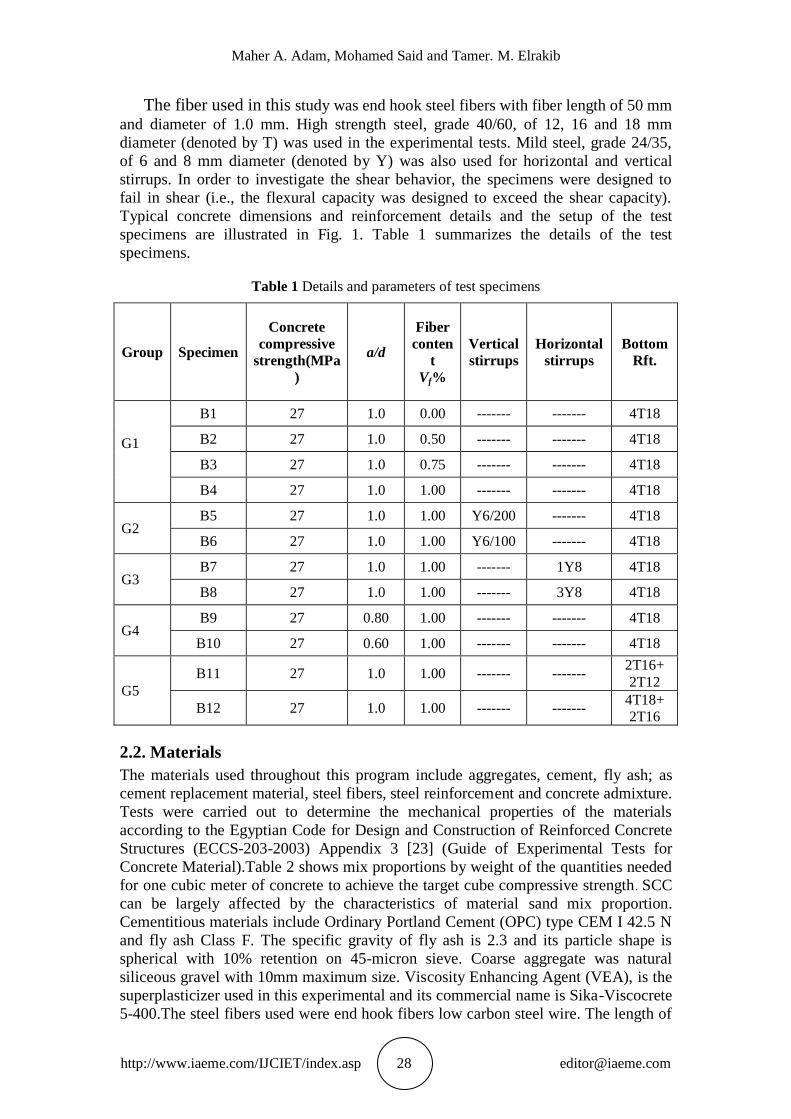
Table 1 Details and parameters of test specimens
Group Specimen
Concrete
compressive
strength(MPa
)
a/d
Fiber
conten
t
Vf%
Vertical
stirrups
Horizontal
stirrups
Bottom
Rft.
G1
B1 27 1.0 0.00 ------- ------- 4T18
B2 27 1.0 0.50 ------- ------- 4T18
B3 27 1.0 0.75 ------- ------- 4T18
B4 27 1.0 1.00 ------- ------- 4T18
G2 B5 27 1.0 1.00 Y6/200 ------- 4T18
B6 27 1.0 1.00 Y6/100 ------- 4T18
G3 B7 27 1.0 1.00 ------- 1Y8 4T18
B8 27 1.0 1.00 ------- 3Y8 4T18
G4 B9 27 0.80 1.00 ------- ------- 4T18
B10 27 0.60 1.00 ------- ------- 4T18
G5
B11 27 1.0 1.00 ------- ------- 2T16+
2T12
B12 27 1.0 1.00 ------- ------- 4T18+
2T16
2.2. Materials
The materials used throughout this program include aggregates, cement, fly ash; as
cement replacement material, steel fibers, steel reinforcement and concrete admixture.
Tests were carried out to determine the mechanical properties of the materials
according to the Egyptian Code for Design and Construction of Reinforced Concrete
Structures (ECCS-203-2003) Appendix 3 [23] (Guide of Experimental Tests for
Concrete Material).Table 2 shows mix proportions by weight of the quantities needed
for one cubic meter of concrete to achieve the target cube compressive strength . SCC
can be largely affected by the characteristics of material sand mix proportion.
Cementitious materials include Ordinary Portland Cement (OPC) type CEM I 42.5 N
and fly ash Class F. The specific gravity of fly ash is 2.3 and its particle shape is
spherical with 10% retention on 45-micron sieve. Coarse aggregate was natural
siliceous gravel with 10mm maximum size. Viscosity Enhancing Agent (VEA), is the
superplasticizer used in this experimental and its commercial name is Sika-Viscocrete
5-400.The steel fibers used were end hook fibers low carbon steel wire. The length of

Shear Performance of Fiber Reinforced Self Compacting Concrete Deep Beams
http://www.iaeme.com/IJCIET/index.asp 29 [email protected]
fiber was 50mm. The diameter was 1mm and the tensile strength was about 1000
MPa.
Table 2 Mix proportions of concrete
High strength steel-deformed type; grade 40/60 of 10, 12 and 16 mm diameter,
and mild steel-smooth type; grade 24/35 of 8 and 10 mm diameter were used in the
experimental tests. Also, the actual area and unit weight were determined. Test results
are given in Table 3.
Table 3 Mechanical properties of steel bars
Nominal
diameter
(mm)
Grade Actual area
(mm2)
Yield
strength
(N/mm2)
Ultimate
strength
(N/mm2)
Elongation
%
6 24/35 28 271 413 21.64
8 24/35 49 274 402 20.51
12 40/60 112 520 672 17.50
16 40/60 199 485 623 18.75
18 40/60 251 426 677 18.25
The slump flow test, T50 cm slump flow and L-box were carried out to investigate
the material characteristics of fresh concrete. These tests were conducted to assess the
flowability and flow rate of SCC in the absence of obstructions. The result of the
slump flow is an indication of the filling ability of SCC. The test result of fresh
concrete properties are shown in Table 4, these results are within the acceptable
criteria for SCC given by ACI committee-363 [24] and indicate excellent
deformability without blocking.
Table 4 Results of testing fresh SCC property in experimental work
Mix Slump flow (mm) T50 (sec) L-box (H2/H1)
SCC 760 2.6 0.93
Limit ACI-363 650-800 2-5 0.8-1
2.3. Instrumentation and test procedure
Test specimens were instrumented to measure the applied load, mid-span deflection,
strain at bottom reinforcement and strains of vertical and horizontal stirrups in the
constant shear force region as shown in Fig. 1. A linear variable displacement
transducer (LVDT) is used to record measurements at fixed time intervals. In
addition; the bi-gauges were used to draw the surface concrete strain distribution
along the beam depth. The load was distributed equally by a spreader beam to two
points along the specimen. The test was continued after the ultimate load in order to
MATERIAL CEMENT
(KG/M3)
FLY ASH
(KG/M3)
DOLOMITE
(KG/M3)
SAND
(KG/M3)
WATER
(LITER/M3)
VISCOCRETE
(VEA)
(LITER/M3)
QUANTITY 350 75 940 1000 206 7.5

Maher A. Adam, Mohamed Said and Tamer. M. Elrakib
http://www.iaeme.com/IJCIET/index.asp 30 [email protected]
evaluate the post peak behavior of the tested beams. The development of cracks was
marked along the sides of the specimens. Auxiliary specimens of cubes and prisms
were tested on the same day of testing of FRSCC beams to determine the mean
compressive strength and modulus of rupture of the concrete respectively.
3. TEST RESULTS
3.1. Cracking behavior
Typical behavior of beams is introduced through cracks pattern distributions recorded
at applied load increments as shown in Fig. 2. The test beams were free of cracks in
the early stages of loading. The initial shear crack inclined or diagonal crack was
developed near the neutral axis in the shear span. With the increase in load, the
shear crack propagated diagonally towards the top and bottom fiber of the beam
with the development of additional shear and flexure cracks along the beam. All
beam specimens failed in shear and shear cracks crossed the compression zone of
beam section as clearly shown in Fig. 2.
For all specimens the shear cracks started without appearance of flexural cracks.
For most of specimens without vertical and horizontal stirrups B1 to B4, B10 and
B11, it was observed that a main crack was formed in the shear span region and
gradually propagated towards the two loading points until failure occurred. In the
other hand, other specimens had two nearly parallel diagonal cracks; in addition, a
series of flexural cracks was formed at the bottom of specimens at zone between
two point loads for these specimens.
The first shear crack in the middle of shear span, with an inclination angle was
about 45o, 51
o and 60
o for beams B4, B9 and B10, respectively. Generally, the first
diagonal crack (shear crack) appears at the middle third of the diagonal region
bounded by load and support positions at a loading level ranges between 53% and 57
% of the ultimate load for specimens with a/d; ratio equal to 1.0. For specimens B9
and B10 with a/d; ratio of 0.8 and 0.6 the first shear crack started at 49% and 45% of
the ultimate load. Similar observation was recorded by CIRIA guide 2 [2]. Al-Khafaji
et al [20] recorded that, for FRSCC deep beam strengthened with 0.8% steel fiber
tested at a/d; ratio equal to 1.0 the diagonal shear crack started at 46% of the ultimate
load. On the other hand, the first crack loads appeared at about 60% to 80% of the
ultimate load for FRSCC deep beam tested by Shad and Modhera [25]. The influence
of fiber content Vf; is very sensitive. The increase of Vf enhances the shear and tension
resistances of concrete and plays an important role to bridge and arrest the cracks.
This is the reason behind the delay of appearance of first flexural and diagonal shear
cracks for FRSCC deep beams.
3.2. Mode of failure
In deep beams, significant part of load is transferred to support directly through
compression struts formed between loads and supporting points. This mechanism of
transferring load leads to the type of failure that is most common in deep beams.

Shear Performance of Fiber Reinforced Self Compacting Concrete Deep Beams
http://www.iaeme.com/IJCIET/index.asp 31 [email protected]
Figure 2 Crack Pattern of FRSCC deep beams

Maher A. Adam, Mohamed Said and Tamer. M. Elrakib
http://www.iaeme.com/IJCIET/index.asp 32 [email protected]
Table 5 Test results
All specimens exhibited the mode of shear failure as shown in Fig. 2. Specimens
B1 to B5 and B11 exhibited a mode of shear failure characterized by splitting of the
web concrete along the line joining the load pad and the beam support. The shear
splitting failure occurred when a main crack developed to split the beam from top to
bottom without crushing of concrete. For specimens failed with shear crushing,
additional parallel diagonal cracks formed a series of concrete struts. One of the struts
was failed by crushing between cracks, as shown in Fig.2. Failure of beams B6, B7
and B8 exhibited the role of horizontal and vertical steel stirrups in changing the
mode of failure and increasing the ultimate load. Generally, at small a/d ratios the
failure of the beams B9 and B10 was characterized by crushing of the web of the
beams. As the shear span to effective depth ratio increased (a/d=1.0), the failure was
characterized by splitting of the web of beam; B4.It is obvious that the significance of
vertical compressive stresses on the shear response of the beam prevails on as the a/d
ratio decreases. The experimental results pointed out that the shear behavior of SCC
deep beams and the conventional vibrated concrete are dissimilar. The shear strength
of FRSCC deep beam is less than conventional vibrated concrete deep beam due to
lesser amount and smaller maximum size of coarse aggregate used in SCC. Evidently
the interlock mechanism of coarse aggregate is weaker which represents an important
part of the total shear strength parts for these members. Similar observation was
recorded by Sultan [26].
Specime
n
Experimental
cracking level
Experimental
ultimate level
NLFEA results Absorbed
energy
(kN.mm)
Faliure
mode
Crackin
g
Ultimat
e
Δc
(mm)
(Pc-exp)
(kN)
Δu
(mm)
(Pu-exp)
(kN)
(Pc-an)
(kN)
(Pu-an)
(kN)
B1 0.38 145.0 1.377 268.2 154.0 270.0 320.8 Shear
splitting
B2 0.53 175.0 1.545 329.3 170.0 324.5 403.6 Shear
splitting
B3 0.60 190.0 2.065 348.5 180.0 341.3 642.3 Shear
splitting
B4 0.70 215.0 2.60 375.4 198.0 387.0 727.3 Shear
splitting
B5 0.85 225.0 3.01 408.6 221.0 400.7 1035.9 Shear
splitting
B6 1.01 250.0 3.67 443.8 240.0 452.0 1478.2 Shear
crushing
B7 0.77 220.0 2.81 399.0 214.0 407.0 892.0 Shear
crushing
B8 0.84 235.0 3.06 445.2 228.0 461.0 1073.4 Shear
crushing
B9 0.78 250.0 3.57 514.4 234.0 512.0 1525.0 Shear
crushing
B10 0.89 270.0 3.55 597.7 260.0 589.0 1653.7 Shear
crushing
B11 0.79 170.0 2.02 302.4 158.0 297.0 476.8 Shear
splitting
B12 0.75 250.0 2.77 441.7 249.0 435.0 1095.4 Shear
crushing

Shear Performance of Fiber Reinforced Self Compacting Concrete Deep Beams
http://www.iaeme.com/IJCIET/index.asp 33 [email protected]
3.3. Load-Deflection Relationship
The load mid-span deflection response was characterized by a linear uncracked
response up to first diagonal cracking, followed by a nonlinear cracked response up to
the peak load. Once the peak load was attained, sudden failure was observed for RC
deepbeams.Fig.3 shows the load-deflection responses of five different series of
beams. In general, deflections of deep beams are small compared with slender beams.
As beam section height increases the stiffness of beam increases leading to brittle
failure. The principal reason for incorporating fibers into a cement matrix is to
improve the crack and deformation characteristics of the composite due to increases in
tensile strength. As shown in Fig. 3a, the increase of steel fibers ratio; Vf leads to an
increase in the ultimate load carrying capacity as a result of the enhanced post-
cracking strength of steel fiber reinforced concrete. Experimental results of specimens
with steel fibers given in table 5 reveal that the enhancement in the ultimate load was
23%, 30% and 40%, for specimens B2 with 0.50%, B3 with 0.75% and B4 with
1.00% steel fibers content, respectively. In addition, increasing the steel fibers content
from 0.0 to 1.0 percent increased the ultimate displacement from 1.37 mm to 2.60 mm
as shown in table 5.
As far as the specimens with fibers ratio of 1.0% are concerned, the load
displacement shown in Fig. 3b proved that the ultimate load is enhanced significantly
with increasing the vertical stirrups content. The maximum increase in the ultimate
load was 18%, and in the ultimate displacement was 41% for specimens B6. On the
other hand, Beam B8, with horizontal stirrups of R8/100 mm, showed improved
ultimate load and post peak behavior. The ultimate load of this beam is higher than
those of beams B7 (R8/200mm) and B4 (without horizontal stirrups) by about 12%
and 19% respectively, as shown in Fig. 3c and table 5. Comparison of test results in
Fig. 3d evinces the greet effect of shear span to depth ratio; a/d, on the shear capacity
of test specimens. The ultimate shear capacity of Beams B9 and B10 was 1.37, and
1.60 times that of Beams B4. Concerning the longitudinal reinforcement ratio, the
ultimate capacity was 302.4, 375.4 and 441.7 kN, and the ultimate displacement
was2.02, 2.60 and 2.77 mm for beams provided with longitudinal steel ratio of 1.0%,
1.6% and 2.2%, respectively; as shown in Fig. 3e for specimens B11, B4 and B12.
3.4. Ductility
The brittle failure reduces the capacity of structural elements and considerably
reduces the ductility and serviceability of the structure. The ability of dissipating the
inelastic deformation energy is one of the significant factors for evaluating the
ductility of the specimens. Based on Mohammadhassani et al. [27] the total dissipated
energy was computed as the sum of the areas enclosed by the displacement. Referring
to Fig. 3, as the displacement level increased, the energy dissipated increased. The
energy dissipation for specimens provided with steel fibers was quite higher as
clarified by the large areas enclosed by the load displacement of these specimens. The
utmost energy dissipation was exhibited by the specimens strengthened using 1.0%
steel fibers as shown in Table 5 and Fig. 4. Experimental results of specimens with
steel fibers reveal that the increasing in the energy dissipation was 25%, 100% and
127%, for specimens with 0.50%, 0.75% and 1.0% steel fibers content, respectively; (
B2, B3 and B4). Increasing the tension reinforcement ratio from 1.0 to 1.6 and 2.2
resulted in 52% and 130% increase in the absorbed energy, respectively. Also, as the
spacing between horizontal and vertical stirrups decreased, the ductility of specimen
increased.

Maher A. Adam, Mohamed Said and Tamer. M. Elrakib
http://www.iaeme.com/IJCIET/index.asp 34 [email protected]
(3a) (3b)
(3c) (3d)
(3e)
Figure 3 Load-deflection relationship for tested specimens

Shear Performance of Fiber Reinforced Self Compacting Concrete Deep Beams
http://www.iaeme.com/IJCIET/index.asp 35 [email protected]
Figure 4 Absorbed energy of the tested specimens
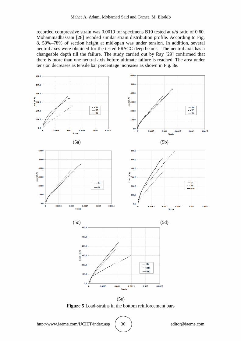
3.5. Strains in reinforcement and concrete
Strain gauges were attached to the bottom steel bar of specimens to investigate the
variation of strain in flexural reinforcement. These gauges were placed at mid-span of
FRSCC specimens. Fig.5 shows the variation of measured strain of the specimens.
The strain variation in longitudinal reinforcement was nearly similar for all tested
specimens and the formation of a tie-action was observed. The strain readings
increased rapidly in the vicinity of the first crack load. Eventually, the strain readings
were increased with uniform rate until the failure load. The maximum strain in
longitudinal tension bars was less than the yield value. The measured strains was
ranged from 48% to 67% of yield strain. The strain gauges situated along the flexural
steel of specimens B2 and B7 were inoperative. The measured strain in bottom
reinforcement indicated that the flexure mode of failure was secured for all of the
specimens to allow for shear mode of failure.
As shown in Fig 6, the strain in vertical stirrups was plotted. The strain in shear
reinforcement stirrups was measured at the critical shear surface in order to gauge its
effectiveness. Prior to cracking, the internal shear resistance was provided by the solid
beam section. Once the inclined cracks occurred, the shear stirrups started to pick up
strains, indicating shear resistance contribution by the vertical stirrups. The maximum
strain in vertical stirrups was about 0.0016 and 0.00175 for specimen B5 and B6,
respectively. The readings of strain in stirrups pointed out that the transverse
reinforcement developed yielding before failure of specimens and also entered the
strain hardening range exhibiting strains much higher than the yield strain which
indicated that the stirrups were successful in resisting the shear stresses in FRSCC
deep beams.
The concrete strain gauges measuring tension perpendicular to compression strut
was recorded. Typical strain profiles for specimens B1 and B7 are drawn in Fig. 7.
The rate of increasing the tensile strain in concrete was very low till just before
the formation of first shear crack, then, increased rapidly with load increase. From the
data collected through strain and bi-gauges reading, the strain distribution through the
height of beam section had been investigated and drawn. It was decided to present the
strain distribution through the height of beam section at the ultimate load. Strain
distributions along the height of mid-span of the twelve FRSCC deep beams tested as
recorded by various bi-gauges at concrete surface are shown in Fig. 8. The stress and
strain distribution in deep beams is nonlinear. The basic assumption for shallow
beams that plane section remains plane after deformation, does not apply for deep
beams. Deep beams exhibit lower strain in the extreme compression fiber. Maximum
Maher A. Adam, Mohamed Said and Tamer. M. Elrakib
http://www.iaeme.com/IJCIET/index.asp 36 [email protected]
recorded compressive strain was 0.0019 for specimens B10 tested at a/d ratio of 0.60.
Mohammadhassani [28] recoded similar strain distribution profile. According to Fig.
8, 50%–78% of section height at mid-span was under tension. In addition, several
neutral axes were obtained for the tested FRSCC deep beams. The neutral axis has a
changeable depth till the failure. The study carried out by Ray [29] confirmed that
there is more than one neutral axis before ultimate failure is reached. The area under
tension decreases as tensile bar percentage increases as shown in Fig. 8e.
(5a) (5b)
(5c) (5d)
(5e)
Figure 5 Load-strains in the bottom reinforcement bars

Shear Performance of Fiber Reinforced Self Compacting Concrete Deep Beams
http://www.iaeme.com/IJCIET/index.asp 37 [email protected]
Figure 6 Load-strains in the vertical stirrups Figure 7 Load-strains (diagonal)
in the concrete
(8a) (8b)
(8c) (8d)

Maher A. Adam, Mohamed Said and Tamer. M. Elrakib
http://www.iaeme.com/IJCIET/index.asp 38 [email protected]
(8e)
Figure 8 Strain distribution of beams at ultimate load
4. EFFECT OF STUDIED PARAMETERS
4.1. Steel fibers content
Four specimens were tested to study the effect of the amount of steel fibers on the
behavior of FRSCC deep beams. The test results show significant improvement in the
cracking and ultimate load-carrying capacities of FRSCC deep beams. Compared to
specimen B1, the increase in the cracking load was 21%, 31% and 78%, and in the
ultimate load was 23%, 30% and 40% for specimens B2, B3 and B4, respectively, as
given in table 5 and Fig. 3a. In addition, increasing the steel fibers content from 0.0 to
1.0 percent increased the ultimate displacement by about 86%. The estimated
absorbed energy confirms the improvement in behavior of the specimens with steel
fibers. The maximum enhancement in the absorbed energy was about 127%. The
improvement in the cracking and ultimate load-carrying capacity is due to the fact that
the steel fibers improve biaxial strength of FRSCC. In deep members, the strut and tie
mechanism development is strongly influenced by the compressed strut biaxial
strength, and the presence of fibers plays a fundamental role, as observed
experimentally in the tested specimens [30].
4.2. Vertical web reinforcement
To investigate the effect of the vertical stirrups on the behavior of FRSCC deep
beams, three beams were analyzed. All specimens had fibers content of 1.0%.
Obviously, the vertical stirrups had no significant effect on the initial stiffness of
specimens B4, B5 and B6 as depicted in Fig. 3b. Provision of the steel stirrups is
shown to enhance the cracking and ultimate capacities of the tested beams. The
enhancement increases with increasing the amount of stirrups and decreasing the
spacing between them. Compared to the control Specimen B4, the increase in the
cracking load was about 5% and 16% for B5 and B6, respectively. on the other hand,
the maximum increasing in the ultimate load was about 19%.The absorbed energy of
specimen B6 was about 2.0 times that of specimen B4. According to ACI 318 [3],
minimum strut reinforcement needs to be provided to avoid splitting failure in struts.
No clear consensus about the role of transverse reinforcement in bottle shaped struts.
Catastrophic failure could be avoided by providing minimum transverse
reinforcement [31].

Shear Performance of Fiber Reinforced Self Compacting Concrete Deep Beams
http://www.iaeme.com/IJCIET/index.asp 39 [email protected]
4.3. Horizontal web reinforcement
Both the vertical and horizontal web reinforcement are efficient in resisting the shear
capacity of deep beams, but the horizontal shear reinforcement is most effective when
aligned perpendicular to the major axis of the diagonal crack [32]. Experimental
results on three specimens; B4, B7 and B8 were investigated to demonstrate the effect
of horizontal web reinforcement on the deep beam performance. The increase in the
cracking and ultimate load due to presence of horizontal stirrups was about10% and
19%, respectively, for B8 as shown in Fig. 3c. Obviously, the horizontal and vertical
web reinforcement had similar effective in providing shear strength for the tested
beams. On the other hand, the horizontal web reinforcement changes the mode of
failure from shear splitting to shear crushing, (see Fig. 2).
4.4. Shear span to effective depth ratio (a/d)
Reserve strength and normalized shear strength decreases when a/d increases. The
shear span to effective depth ratio is highly influencing parameter of deep beams
shear strength. Specimens B4, B9 and B10 were tested to investigate the effect of the
shear span to depth ratio on FRSCC deep beams (see Fig. 3d). Decreasing the (a/d)
ratio from 1.0 to 0.8 and 0.60 resulted in 16% and 26% increase in the cracking load,
respectively, and resulted in 37% and 60% enhancement in the ultimate load,
respectively, (see table 5). The maximum recorded compressive strain was about
0.002 for specimen B10 tested at a/d; ratio of 0.6.
4.5. Longitudinal steel reinforcement
Specimens B4, B11 and B12 were tested to demonstrate the effect of longitudinal
reinforcement amount on the FRSCC deep beam performance. The load displacement
was shown in Fig. 3e.The enhancement in the cracking and ultimate load was about
47%. The maximum improvement in the absorbed energy was 130% for specimen
B12. Increase in the reinforcement ratio resulted in increase in ultimate load energy
absorption and number of cracks. Beams with high tension reinforcement ratio endure
the load beyond the elastic stage with less deflection. Clearly, compression strut fails
when the tension capacity is high [27].
5. NON-LINEAR FINITE ELEMENTS ANALYSES
Finite elements method becomes a reliable tool in determining the stresses in the
structure during linear and non-linear stage of loading. Application of the non-linear
finite elements analysis (NLFEA) to a reinforced concrete structure is largely
dependent on the stress-strain relationships, failure criteria, simulation of steel
reinforcement and interaction between steel and concrete. NLFEA investigation of the
shear behavior of the tested FRSCC deep beams was carried out using the finite
element software “ANSYS 10.0” [22]. The load deflection curve is considered the key
aspect in studying the FRSCC deep beams behavior as it involves many response
parameters including beam ultimate strength, maximum deformation and cracking
behavior. Therefore, correlating the load-deflection relationships of the analytical
results with that of the experimental ones is considered an effective mean to verify the
non-linear model. Numerous previous studies were carried to study shear behavior of
reinforced concrete beams using ANSYS software [33, 34].

Maher A. Adam, Mohamed Said and Tamer. M. Elrakib
http://www.iaeme.com/IJCIET/index.asp 40 [email protected]
5.1. Finite element model
Non-linear finite elements analysis was carried out using a computer package
“ANSYS 10.0”. An 8-node solid element with three translational and additional
rotational degrees of freedom at each node was chosen to idealize the concrete
whereas a 2-node bar element was used to model the steel rebars. Specimens were
typically discretized using 3000 of nearly equal-size 3-D isoparametric elements;
Solid65 as shown in Fig. 9a. Both linear and non-linear behaviors of the concrete
were considered. The concrete was assumed to be an isotropic material up to cracking
stage and then to undergo plasticity. Cracking may take place in three orthogonal
directions at each integration point. The stress-strain curve and behavior of SCC
based on results from Maghsoudi and Arabpour [35] were adopted. The addition of
steel fibers increases the strain corresponding to the peak stress but does not produce
any significant change in the compressive strength. The steel fibers were represented
by discrete model. The reinforcing bars were idealized using a 2-node bar (linear)
element; Link8 as shown in Fig. 9b. In this study the main and web steel
reinforcement are modeled as discrete and embedded, and the steel fiber modeled as
smeared model.
To account for aggregate interlock dowel action and steel fibers content for
FRSCC, the transfer of shear stresses is modeled numerically using a constant fraction
shear retention model. Shear transfer coefficients were taken as 0.125, 0.150, 0.175 or
0.20 for open crack and 0.60, 0.625, 0.65 or 0.675 for closed crack, for fibers ratio of
nil, 0.50, 0.75 and 1.0, respectively. A value of 0.6 for stress relaxation after cracking
was considered in the analysis.
(9a) concrete element; Solid65; (9b) reinforcing bar element; Link8
Figure 9 Typical idealization of test beam
5.2. NLFEA predictions
A correlative study, based on the cracking and ultimate capacities, and load
displacement, was conducted to verify the analytical model with the experimental
results. Referring to Table 5, the predicted cracking loads; Pc-an are shown to be in a
good agreement with the experimental loads; Pc-exp with a mean Pc-an / Pc-exp ratio of
0.97 and a standard deviation of 3.7%. The ratio of the predicted to experimental
ultimate strength for the columns ranged between 0.98 and 1.04, with a mean value of
1.01 and a standard deviation of 2.0%. Implicitly, the analysis reflected the

Shear Performance of Fiber Reinforced Self Compacting Concrete Deep Beams
http://www.iaeme.com/IJCIET/index.asp 41 [email protected]
significance of test parameters investigated on the load-carrying capacity.
Furthermore, the analysis adequately reflected the enhancement in the ultimate
capacity recorded for specimens provided with steel fibers. Output sample for NLFEA
indicating the cracks propagation for beams B6 and B10 were given in Fig. 10. All
beam specimens exhibited similar predicted patterns of crack development and
propagation.
(10a) specimen B6
(10b) specimen B10
Figure 10 Cracks propagation for specimen B6 and B10
For specimen B12, the predicted shear and normal stresses distribution along the
beam at ultimate load were presented in Fig. 11. The maximum analytical
compressive and tensile stress for concrete was 20.5MPa and 2.3MPa, respectively.
On the other hand, the shear stress in concrete was symmetrical and the maximum
shear stress about 9.8 MPa.
(11a) shear stress; (11b) normal stress
Figure 11 Concrete stress distribution for specimen B12 at ultimate load
Figure 12 shows the analytical results compared with the load deflection curve for
all FRSCC deep beam specimens. The analytical results of the ultimate loads of most
of the specimens were very close to the experimental results. In conclusion, to the
range of the test parameters investigated, the application of non-linear finite elements
model presented in this study yielded satisfactory cracking load, load-carrying
capacity, and load-deflection response.

Maher A. Adam, Mohamed Said and Tamer. M. Elrakib
http://www.iaeme.com/IJCIET/index.asp 42 [email protected]
(12a) specimen B1 (12b) specimen B2
(12c) specimen B3 (12d) specimen B4
(12e) specimen B5 (12f) specimen B6
(12g) specimen B7 (12h) specimen B8

Shear Performance of Fiber Reinforced Self Compacting Concrete Deep Beams
http://www.iaeme.com/IJCIET/index.asp 43 [email protected]
(12i) specimen B9 (12j) specimen B10
(12k) specimen B11 (12l) specimen B12
Figure 12 Experimental and NLFEA Load-deflection relationship for tested
specimens
6. CONCLUSIONS
Based on the current investigation, the main findings may be summarized as follow:
Provision of the steel fibers enhanced the cracking load, ultimate capacity,
displacement and energy absorption of tested SCC deep beams. The utmost
enhancement in the performance of beams was achieved with steel fibers content of
1.0% according to the range of the investigated parameters. The enhancement in the
ultimate capacity and displacement was about 40% and 50%, respectively. The
corresponding improvement in the energy absorption capacity was about 127%.
The contribution of vertical web reinforcement to the shear capacity is proportional to
the amount of shear reinforcement. The maximum increase in the shear capacity was
about 19% for the range of the tested beams.
The horizontal shear reinforcement can improve the shear strength of reinforced
concrete deep beams as well as the vertical reinforcement. The load-carrying
capacities of the beams with horizontal web reinforcement were 106% and 119% of
that of the beam without horizontal web reinforcement.
The failure of FRSCC deep beams without horizontal stirrups was classified as shear
splitting failure whereas the corresponding beams with horizontal web reinforcement
experienced a shear crushing mode of failure.

Maher A. Adam, Mohamed Said and Tamer. M. Elrakib
http://www.iaeme.com/IJCIET/index.asp 44 [email protected]
Decreasing the shearing span to depth ratio increased the shear capacity of the
concrete beams. Decreasing the shearing span to depth ratio from 1.0 to 0.6 led to
increasing in the crack and failure load of the beam by 26% and 60 %, respectively.
The ultimate shear capacity increases as the amount of main flexural steel increases
pointing out the necessity of increasing the flexural reinforcement in the deep beam.
The shear capacity increased with about 47% with increasing the longitudinal steel
ratio from 1.0% to 2.2%.
Strain distribution at the section height of mid span length is nonlinear with more
than one neutral axis depth. Maximum measured strain in extreme compression fiber
of concrete section is 0.0019.
Application of non-linear finite elements model to test beams, yielded acceptable
load-carrying capacities, cracking behavior and load displacement. The analysis
adequately reflected the trend of experimental results.
The experimental and analytical results pointed out that the deep beams work as a
tied arch. The compression strut formed between the loading point and the support is
under biaxial compression tension stresses. Beams with a shear span to depth ratio of
less than 1.0 will work as tied arches provided that the main reinforcement is well
anchored beyond the support.
The construction of RC specimens can be time-consuming and labor-intensive due to
the complicated detailing of reinforcing bars in contrast to the FRSCC specimens.
The current findings represent good encouragement for the application engineers
toward the use of FRSCC in deep beam structures.
REFERENCES
[1] Kong F. G., (2003), "Reinforced concrete deep beams," 2nd ed., Taylor &
Francis, pp.2.
[2] CIRIA Guide 2, (1984),"The design of deep beams in reinforced concrete,"
London: Over Arup and Partners, and Construction Industry Research and
Information Association; pp. 131.
[3] ACI Committee 318, (2014), “Building code requirements for reinforced concrete
(ACI 318-14) and commentary (ACI 318R-14),” American Concrete Institute,
Farmington Hills, Mich.
[4] Narayanan, R., and Darwish, I. Y. S., (1989), “Fiber concrete deep beams in
shear,” ACI Structural Journal. 85, pp. 141-149.
[5] Mansur, M. A., and Ong, K. C. G., (1991), “Behavior of reinforced fiber concrete
deep beams in shear,” ACI Structural Journal. 88, No. 1, pp. 98-105.
[6] Ward, R., and Hamza, A. M., (1992), “Steel and synthetic fibers as shear
reinforcement,” ACI Structural Journal, V. 89, No. 5, pp. 499-508.
[7] Tan, K. H., Murugappan, K., and Parasivam, P., (1993), “Shear behavior of steel
fiber reinforced concrete beams,” ACI Structural Journal. 90, No. 1, pp. 499-508.
[8] Campione, G., (2012), “Performance of steel fibrous reinforced concrete corbels
subjected to vertical and horizontal loads,” ASCE Journal of Structural
Engineering. 138, No. 2, pp. 235-246.
[9] Lee, H. H., (2007), “Shear strength and behavior of steel fiber reinforced concrete
columns under cyclic loading,” Science Direct, Engineering Structures 29. pp.
1253-1262.
[10] Kimura, H., Kambayashi, A., and Takatsu, H., (2007), “Seismic behavior of 200
MPaultr-high-strength steel fiber reinforced concrete columns under varying axial
load,” Journal of Advanced Concrete Technology, V. 5, No. 2, pp. 193-200.

Shear Performance of Fiber Reinforced Self Compacting Concrete Deep Beams
http://www.iaeme.com/IJCIET/index.asp 45 [email protected]
[11] ACI Committee 237, (2007), “Self-consolidating concrete,” ACI 237R-07, ACI
Committee 237Report, American Concrete Institute, Farmington Hills, Michigan,
pp. 32.
[12] Okamura, H., (1999), “Self-compacting high performance concrete, Tokyo:
Social System Institute.
[13] Okamura, H., Maekawa, K., and Ozawa, K., (1998), High performance concrete,”
Tokyo: Gihoudou Publication.
[14] Choulli, Y., Marı´, A. R., and Cladera, A., (2008), Shear behavior of full-scale
prestressed I-beams made with self compacting concrete,” Materials and
Structures, V. 41, pp. 131-141.
[15] Hassan, A. A. A., Hossain, K. M. A., and Lachemi, M., (2008), “Behavior of full-
scale self-consolidating concrete beams in shear,” Cement and Concrete
Composites, V. 30, pp. 588-596.
[16] Hassan, A. A. A., Hossain, K. M. A., and Lachemi, M., (2010), “Structural
assessment of corroded self-consolidating concrete beams,” Engineering
Structures, V. 32, pp. 874-885.
[17] Lachemi, M., Hassain, K. M. A., Lambros, V., Nkinamubanzi,P. C., and
Bouzoubaa, N., (2005),“Self-compacting concrete in corporating new viscosity
modifying admixtures,” Cement and Concrete Research, V. 24, pp. 917-926.
[18] Hassan, S. A., (2012), “Behavior of reinforced concrete deep beams using self
compacting concrete,” PhD Thesis, University of Baghdad, Civil Department,
Baghdad, Iraq, pp. 164.
[19] Mahmoud, K.Sh, (2012), Experimental study of the shear behavior of self
compacted concrete T-beams, Journal of Engineering and Development, Vol. 16,
No.1.
[20] Al-Khafaji, J., Al-Shaarbaf, I., and Wisam, W.H., (2014), Shear behavior of self
compacting concrete deep beams, Journal of Engineering and Development, Vol.
18, No.2.
[21] Mohammadhassani, M., (2011), An experimental investigation on bending
stiffness and neutral axis depth variation of over-reinforced high strength
concrete beams,” Nuclear Engineering. V. 241, pp. 2060-2067.
[22] ANSYS®, (2006), Engineering Analysis System User's Manual, Vol. 1 & 2, and
Theoretical Manual”, Revision 10.0, Swanson Analysis System Inc., Houston,
Pennsylvania.
[23] ECCS-203, (2003), Egyptian code for design and construction of reinforced
concrete Structures, Housing and Building Research Center, Egypt.
[24] ACI Committee 363, (1992), State-of-the-Art Report on High-Strength Concrete
(ACI363R-92),” American Concrete Institute, Farmington Hills, Michigan,
pp.55.
[25] Shah, D.L., and Modhera, C.D., (2010), Evalution of shear Strength of Self
Compacting Concrete Deep Beam, International Journal of Advanced
Engineering and Technology. V.I, Issue II, pp. 292-305.
[26] Sultan, W. H., (2013), “Behavior of steel fibers reinforced self compacting
concrete deep beams under shear effect, PhD Thesis, University of Al-
Mustansirya, Civil Department, Baghdad, Iraq, pp. 240.
[27] Mohammadhassani, M., Jumaat, M.Z., Ashour, A., and Jameel, M. An.,(2011),
Failure modes and serviceability of high strength self compacting concrete deep
beams, Engineering Failure Analysis 18, pp. 2272-2281
[28] Mohammadhassani, M., (2011), “Experimental and analytical study on HSSCC
deep beams,” PhD thesis, University of Malaya, Kuala Lumpur, Malaysia.

Maher A. Adam, Mohamed Said and Tamer. M. Elrakib
http://www.iaeme.com/IJCIET/index.asp 46 [email protected]
[29] Ray, SP, (2011), Behaviour and ultimate shear strength of reinforced concrete
deep beams with and without opening in web, PhD thesis, Indian Institute of
Technology, Kharagpur, India.
[30] Campione, G, (2012), Flexural behavior of steel fibrous reinforced concrete deep
beams,” ASCE Journal of Structural Engineering. V.138, No.2, 2012, pp. 235-
246.
[31] Raj, J. L., and Rao, G. A., (2013), Performance of RC Deep Beams with
Different Combinations of Web Reinforcement, Applied Mechanics and
Materials, V. 343, pp. 21-26.
[32] Arabzadeh, A., Aghayari, R., and Rahai, A. R. (2011), “Investigation of
experimental and analytical shear strength of reinforced concrete deep beams,”
International Journal of Civil Engineering. V. 9. No. 3. pp. 207-214.
[33] Said, M., Adam, M. A., Mahmoud, A. A., and Shanour A. S., (2016),
Experimental and analytical shear evaluation of concrete beams reinforced with
glass fiber reinforced polymers bars, Construction and Build. Material. V. 102.
pp. 574-591.
[34] R. M. Sawant, Junaid Khan, Jabeen Khan and Satish Waykar. Behavior of High
Strength Fiber Reinforced Concrete Under Shear, International Journal of Civil
Engineering and Technology, 6(4), 2015, pp. 46-54.
[35] Javaid Ahmad, Dr. Javed Ahmad Bhat and Umer Salam. Behavior of Timber
Beams Provided with Flexural as Well as Shear Reinforcement In The Form of
CFRP Strips, International Journal of Advance Research in Engineering and
Technology, 4(6), 2013, pp. 153-165.
[36] Majeed, H. Q., (2012), “Nonlinear finite element analysis of steel fiber reinforced
concrete deep beams with and without opening,” Journal of Engineering and
Development, Vol. 18, No.2.
[37] Maghsoudi. A. A and Arabpour Dahooei. (2005), Effect of Nan scale Materials in
Engineering Properties of Performance Self Compacting Concrete,” 7th
International Conf. In Civil Eng., University of Tarbiat Modares, Tehran. Iran.
[38] Dharane Sidramappa Shivashankar. Ferrocement Beams and Columns with X
Shaped Shear Reinforcement and Stirrups, International Journal of Civil
Engineering and Technology, 5(7), 2015, pp. 172-175.