Shark Animation PDF Tutorial - Blender 3D Design Course
69
Course: 3D Design Title: Shark Animation Blender: Version 2.6X Level: Beginning Author; Neal Hirsig ([email protected] ) (May 2012) Shark Animation In this tutorial, we will animate a shark model created in an earlier tutorial and place it in an underwater scene and create a video file. You can view this Video file HERE . If you do not have the earlier shark modeling tutorial blend file, you can use the “Shark_Modeling_Complete.blend” file located HERE . Open the earlier shark modeling blend file. Save this file as SharkAnimation.blend.
Transcript of Shark Animation PDF Tutorial - Blender 3D Design Course
Course: 3D Design Title: Shark Animation Blender: Version 2.6X Level: Beginning Author; Neal Hirsig ([email protected]) (May 2012)
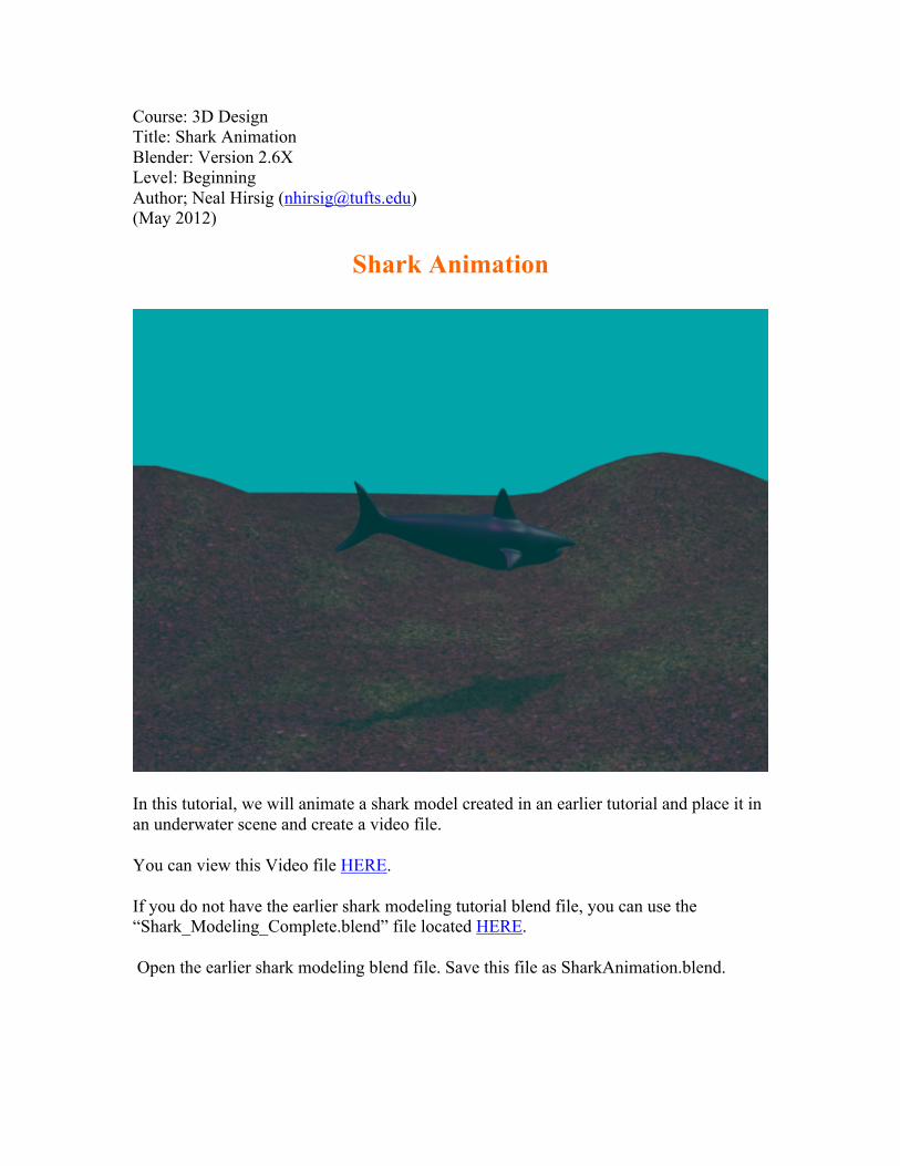
Shark Animation
In this tutorial, we will animate a shark model created in an earlier tutorial and place it in an underwater scene and create a video file.
You can view this Video file HERE.
If you do not have the earlier shark modeling tutorial blend file, you can use the “Shark_Modeling_Complete.blend” file located HERE.
Open the earlier shark modeling blend file. Save this file as SharkAnimation.blend.
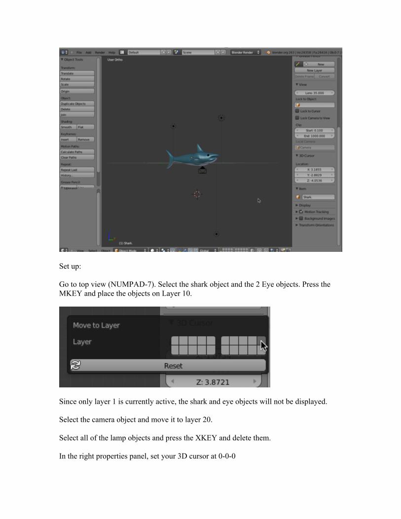
Set up:
Go to top view (NUMPAD-7). Select the shark object and the 2 Eye objects. Press the MKEY and place the objects on Layer 10.
Since only layer 1 is currently active, the shark and eye objects will not be displayed.
Select the camera object and move it to layer 20.
Select all of the lamp objects and press the XKEY and delete them.
In the right properties panel, set your 3D cursor at 0-0-0
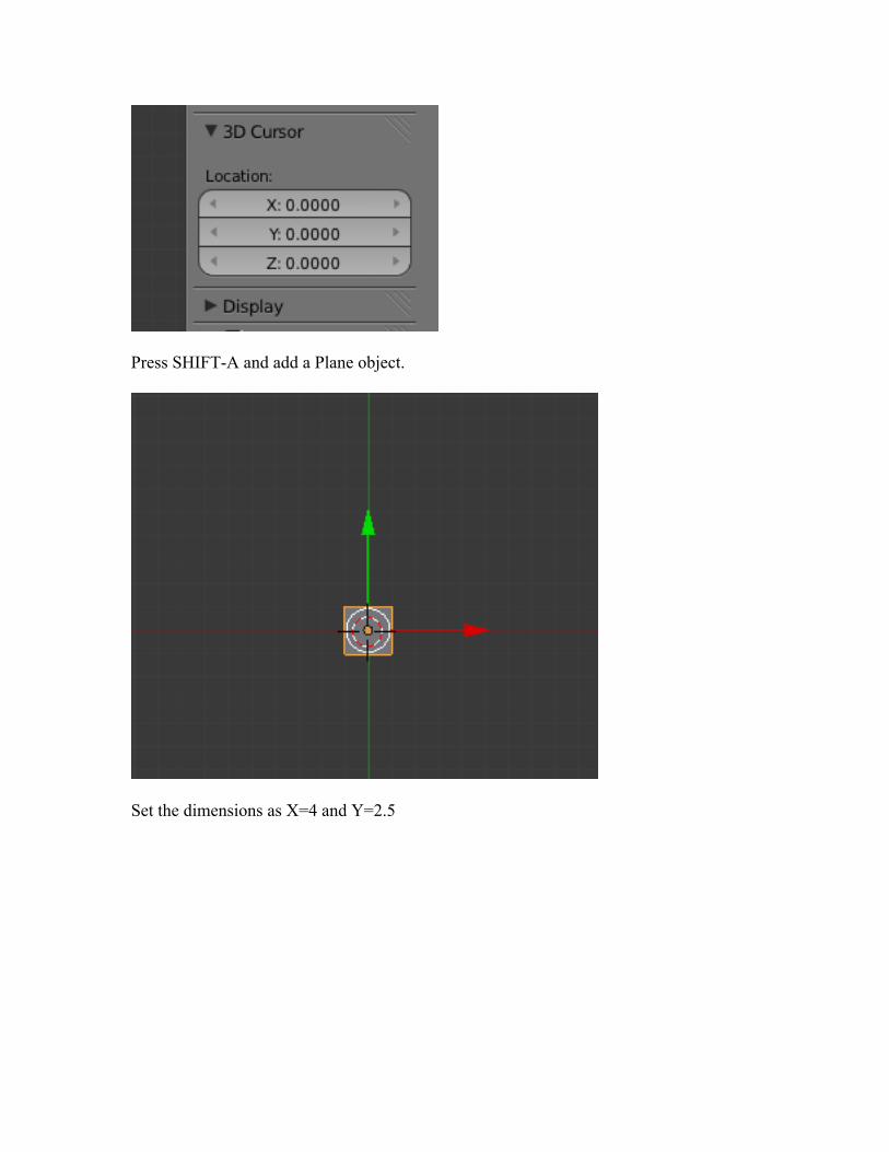
Press SHIFT-A and add a Plane object.
Set the dimensions as X=4 and Y=2.5
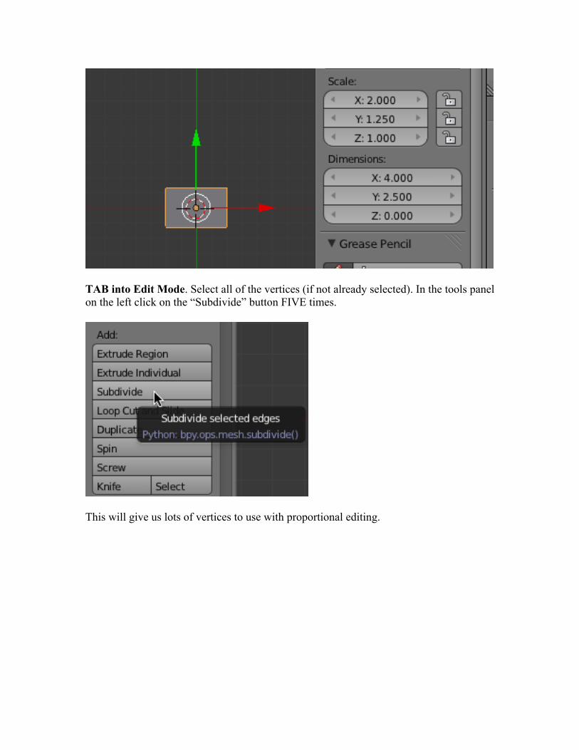
TAB into Edit Mode. Select all of the vertices (if not already selected). In the tools panel on the left click on the “Subdivide” button FIVE times.
This will give us lots of vertices to use with proportional editing.
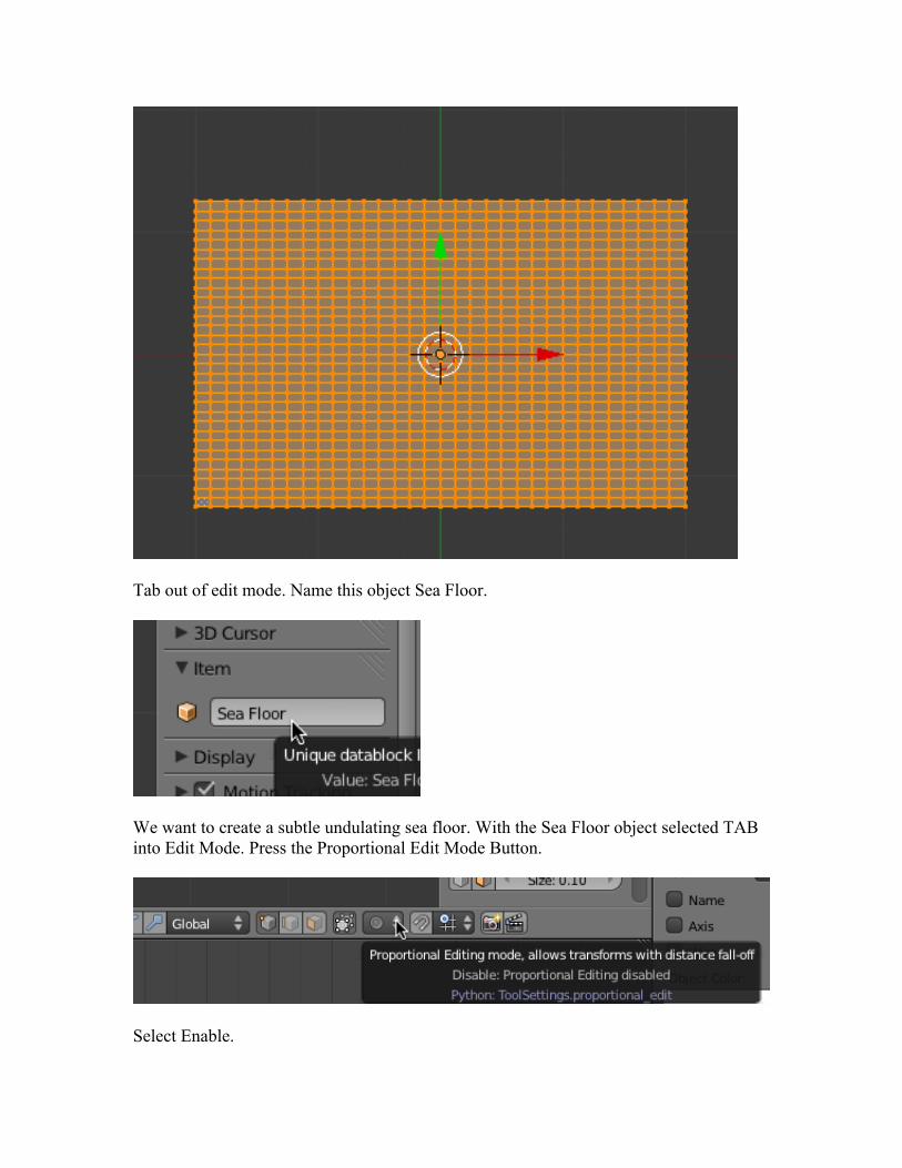
Tab out of edit mode. Name this object Sea Floor.
We want to create a subtle undulating sea floor. With the Sea Floor object selected TAB into Edit Mode. Press the Proportional Edit Mode Button.
Select Enable.
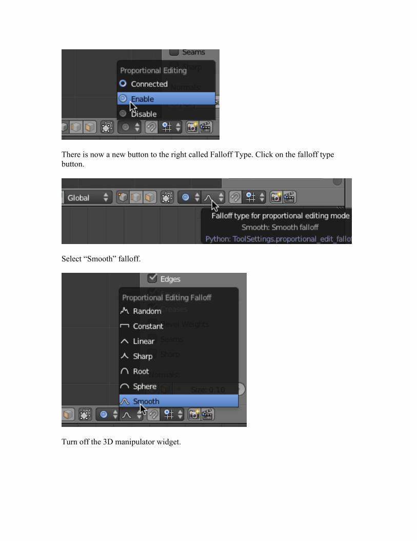
There is now a new button to the right called Falloff Type. Click on the falloff type button.
Select “Smooth” falloff.
Turn off the 3D manipulator widget.
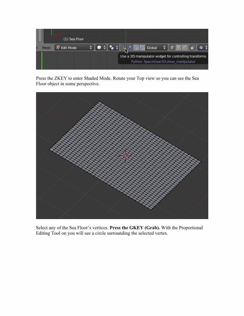
Press the ZKEY to enter Shaded Mode. Rotate your Top view so you can see the Sea Floor object in some perspective.
Select any of the Sea Floor’s vertices. Press the GKEY (Grab). With the Proportional Editing Tool on you will see a circle surrounding the selected vertex.
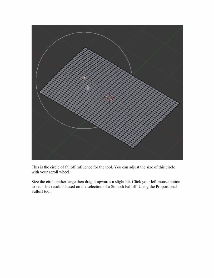
This is the circle of falloff influence for the tool. You can adjust the size of this circle with your scroll wheel.
Size the circle rather large then drag it upwards a slight bit. Click your left mouse button to set. This result is based on the selection of a Smooth Falloff. Using the Proportional Falloff tool.
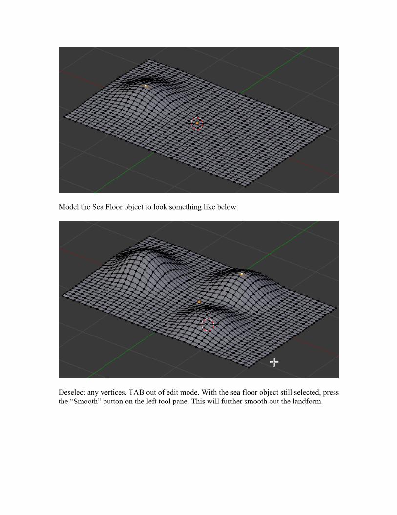
Model the Sea Floor object to look something like below.
Deselect any vertices. TAB out of edit mode. With the sea floor object still selected, press the “Smooth” button on the left tool pane. This will further smooth out the landform.
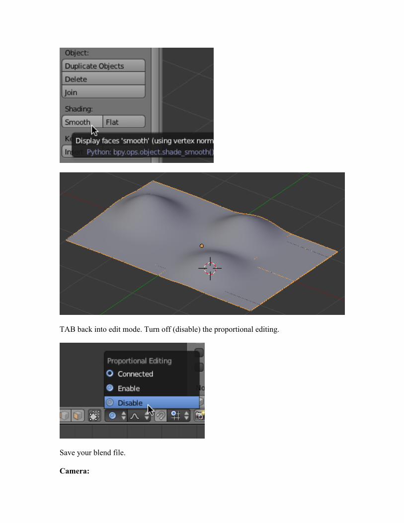
TAB back into edit mode. Turn off (disable) the proportional editing.
Save your blend file.
Camera:
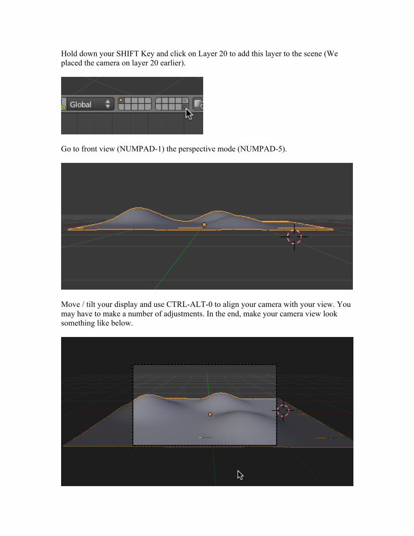
Hold down your SHIFT Key and click on Layer 20 to add this layer to the scene (We placed the camera on layer 20 earlier).
Go to front view (NUMPAD-1) the perspective mode (NUMPAD-5).
Move / tilt your display and use CTRL-ALT-0 to align your camera with your view. You may have to make a number of adjustments. In the end, make your camera view look something like below.
Note that we only see a portion of the sea floor.
When you are satisfied, go to top view (NUMPAD-7).
Save your blend file.
Materials:
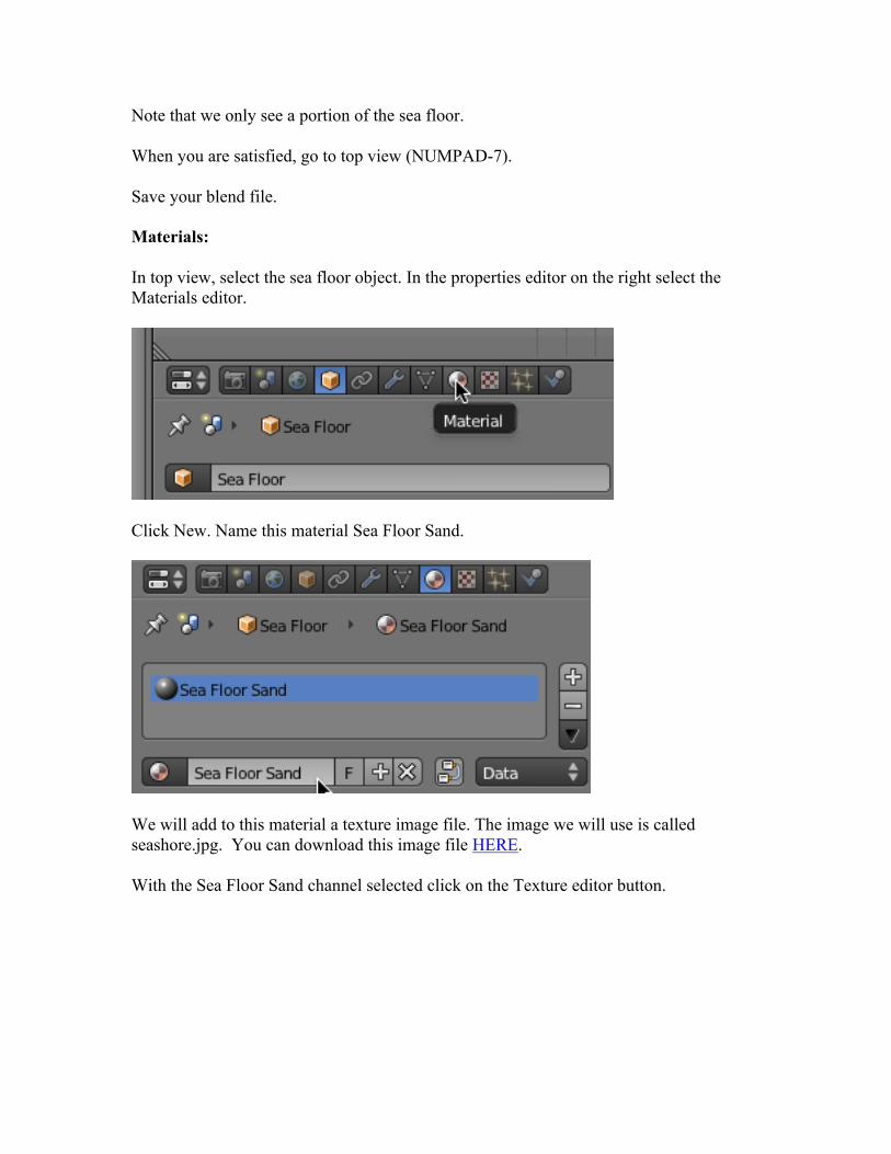
In top view, select the sea floor object. In the properties editor on the right select the Materials editor.
Click New. Name this material Sea Floor Sand.
We will add to this material a texture image file. The image we will use is called seashore.jpg. You can download this image file HERE.
With the Sea Floor Sand channel selected click on the Texture editor button.
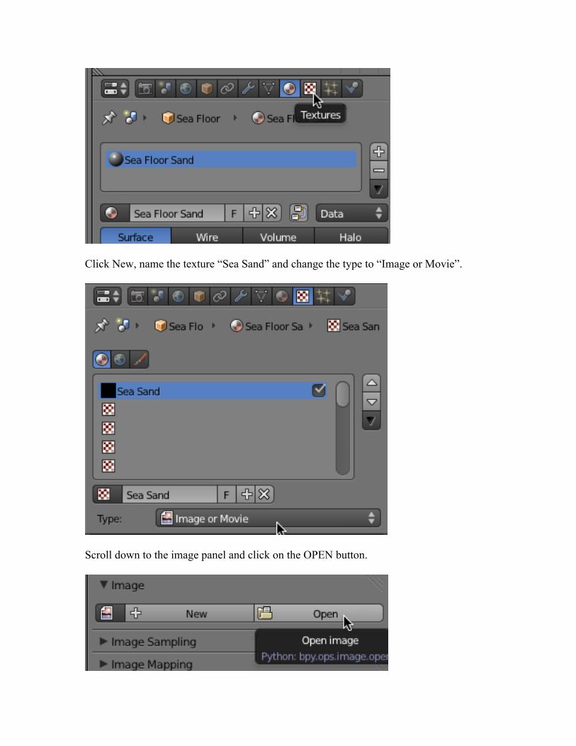
Click New, name the texture “Sea Sand” and change the type to “Image or Movie”.
Scroll down to the image panel and click on the OPEN button.
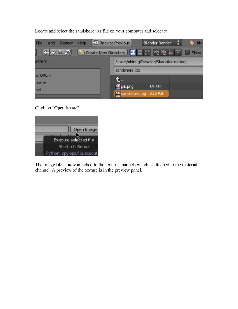
Locate and select the sandshore.jpg file on your computer and select it.
Click on “Open Image”
The image file is now attached to the texture channel (which is attached to the material channel. A preview of the texture is in the preview panel.
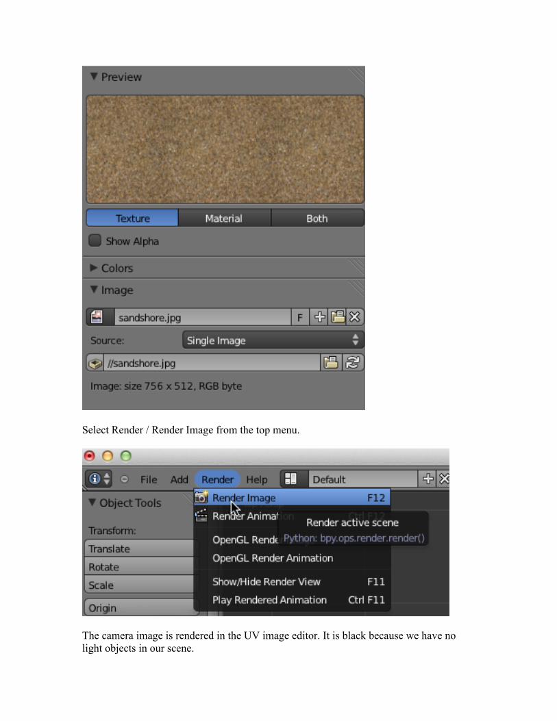
Select Render / Render Image from the top menu.
The camera image is rendered in the UV image editor. It is black because we have no light objects in our scene.
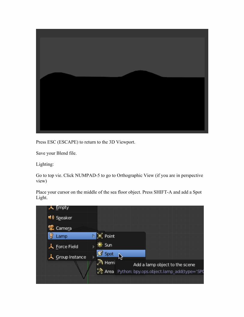
Press ESC (ESCAPE) to return to the 3D Viewport.
Save your Blend file.
Lighting:
Go to top vie. Click NUMPAD-5 to go to Orthographic View (if you are in perspective view)
Place your cursor on the middle of the sea floor object. Press SHIFT-A and add a Spot Light.
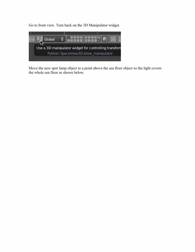
Go to front view. Turn back on the 3D Manipulator widget.
Move the new spot lamp object to a point above the sea floor object so the light covers the whole sea floor as shown below.
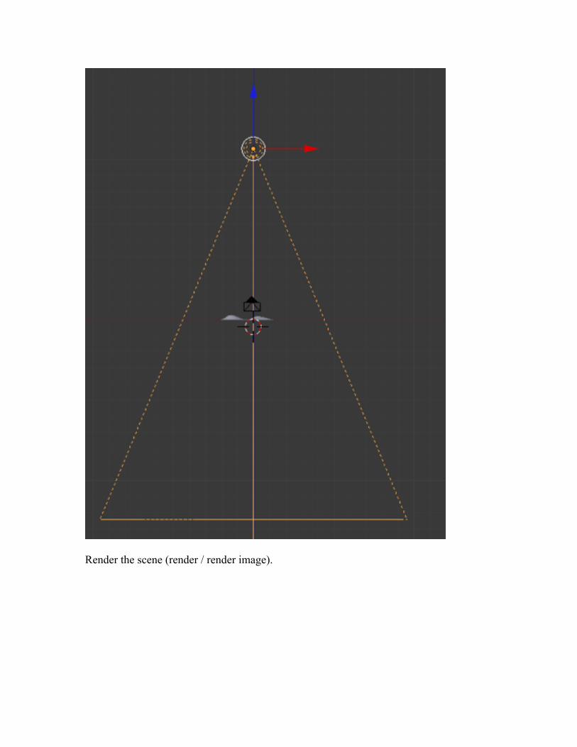
Render the scene (render / render image).
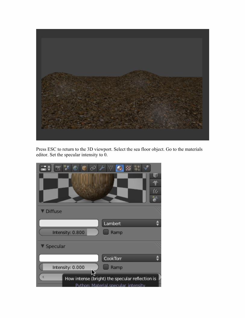
Press ESC to return to the 3D viewport. Select the sea floor object. Go to the materials editor. Set the specular intensity to 0.
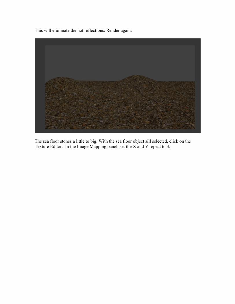
This will eliminate the hot reflections. Render again.
The sea floor stones a little to big. With the sea floor object sill selected, click on the Texture Editor. In the Image Mapping panel, set the X and Y repeat to 3.
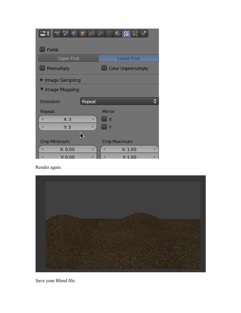
Render again.
Save your Blend file.
World Background:
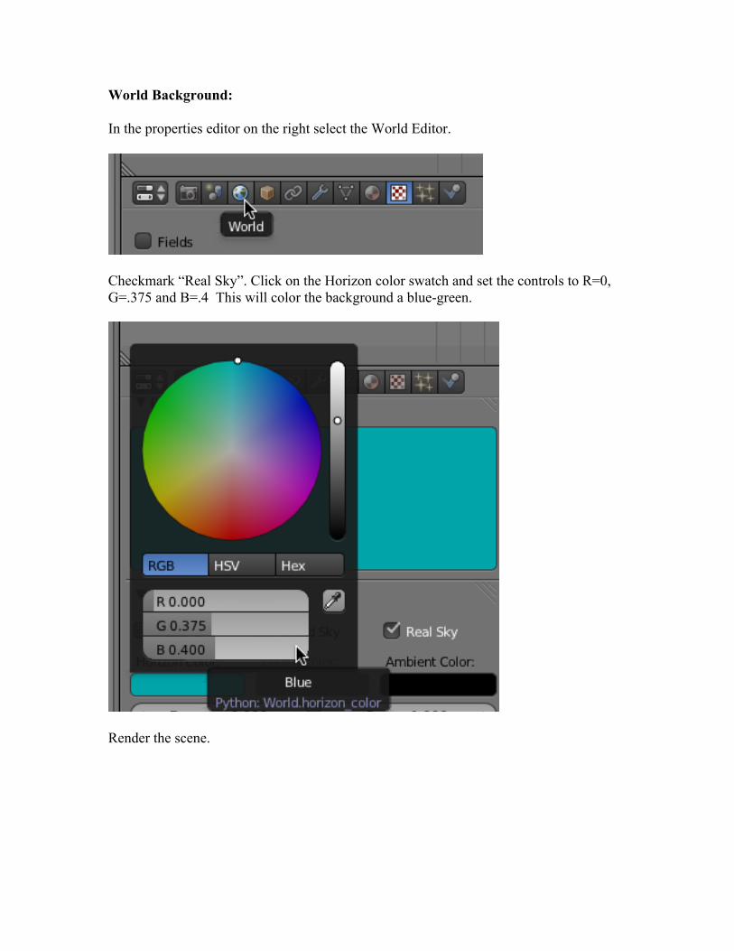
In the properties editor on the right select the World Editor.
Checkmark “Real Sky”. Click on the Horizon color swatch and set the controls to R=0, G=.375 and B=.4 This will color the background a blue-green.
Render the scene.
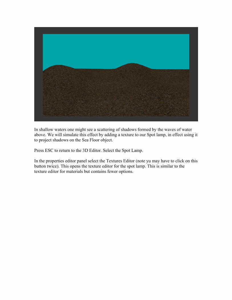
In shallow waters one might see a scattering of shadows formed by the waves of water above. We will simulate this effect by adding a texture to our Spot lamp, in effect using it to project shadows on the Sea Floor object. Press ESC to return to the 3D Editor. Select the Spot Lamp.
In the properties editor panel select the Textures Editor (note yu may have to click on this button twice). This opens the texture editor for the spot lamp. This is similar to the texture editor for materials but contains fewer options.
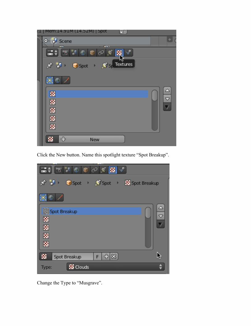
Click the New button. Name this spotlight texture “Spot Breakup”.
Change the Type to “Musgrave”.
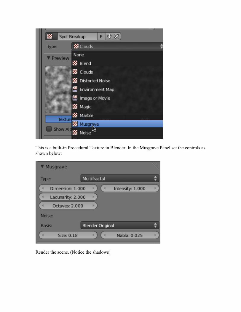
This is a built-in Procedural Texture in Blender. In the Musgrave Panel set the controls as shown below.
Render the scene. (Notice the shadows)
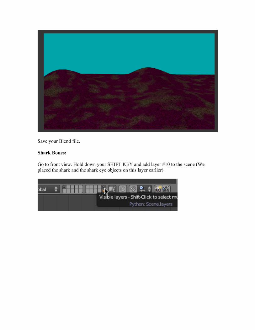
Save your Blend file.
Shark Bones:
Go to front view. Hold down your SHIFT KEY and add layer #10 to the scene (We placed the shark and the shark eye objects on this layer earlier)
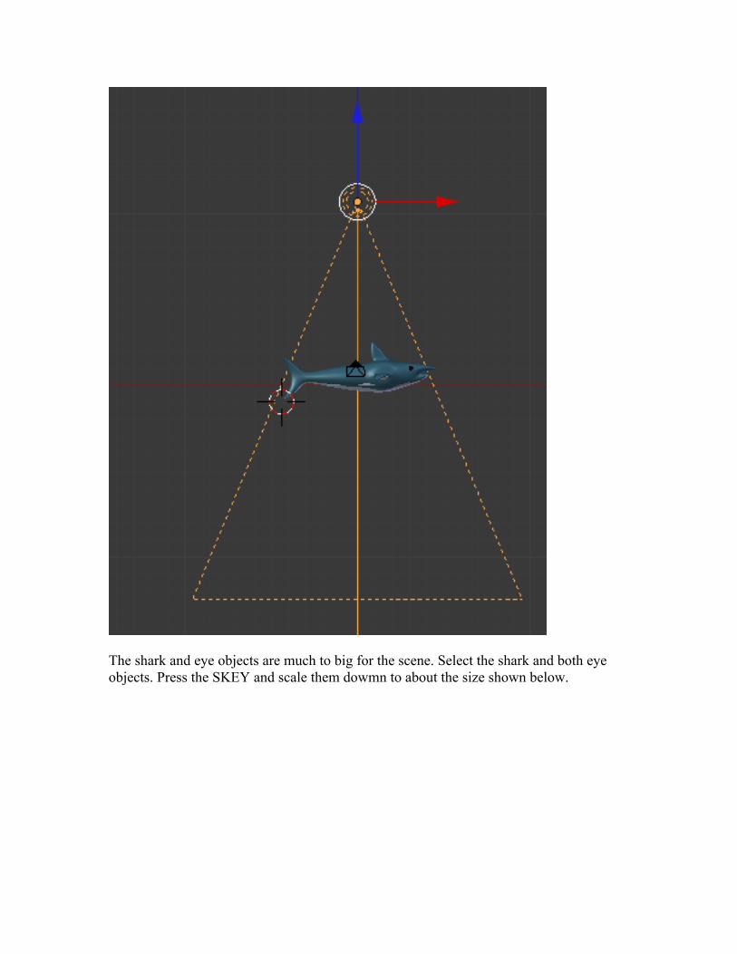
The shark and eye objects are much to big for the scene. Select the shark and both eye objects. Press the SKEY and scale them dowmn to about the size shown below.

Zoom in on the Shark. The shark has a subsurface modifier applied to it. We need to apply that modifier so we end up with a mesh that we can animate.
Deselect all objects. Select only the shark object. With the shark object selected, go to the Object Modifiers Editor.
Click on the “apply” button. This will apply the modifier to the object permanently.
Go to wireframe view. TAB into edit mode.
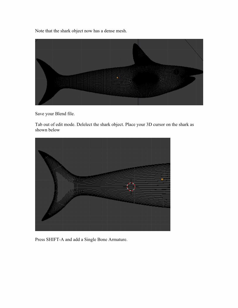
Note that the shark object now has a dense mesh.
Save your Blend file.
Tab out of edit mode. Delelect the shark object. Place your 3D cursor on the shark as shown below
Press SHIFT-A and add a Single Bone Armature.
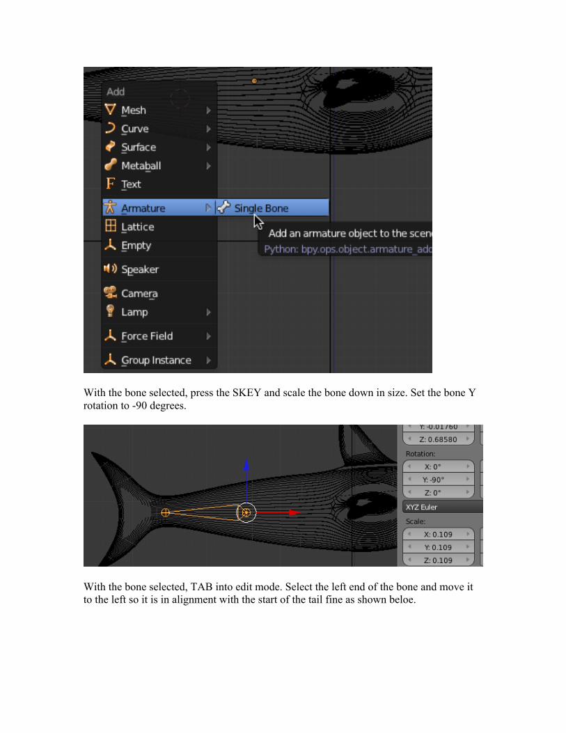
With the bone selected, press the SKEY and scale the bone down in size. Set the bone Y rotation to -90 degrees.
With the bone selected, TAB into edit mode. Select the left end of the bone and move it to the left so it is in alignment with the start of the tail fine as shown beloe.
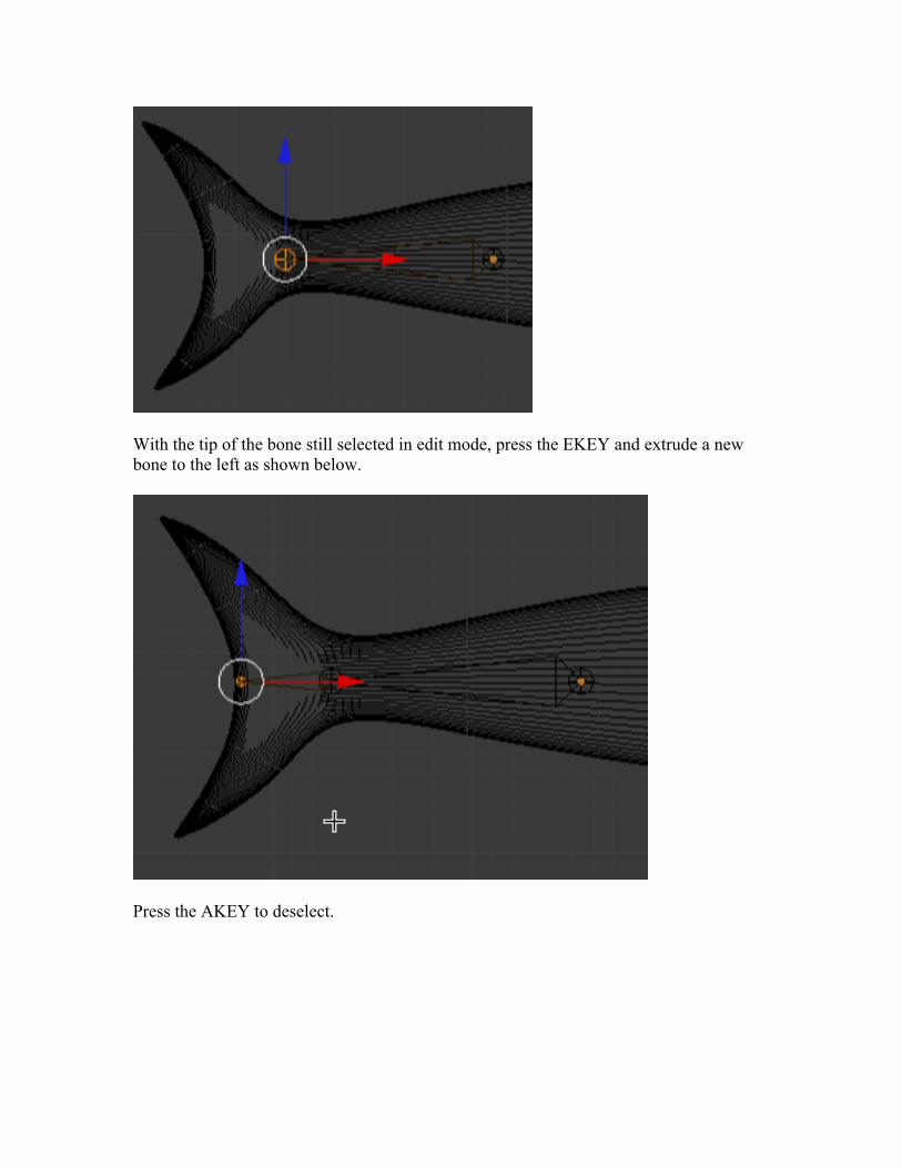
With the tip of the bone still selected in edit mode, press the EKEY and extrude a new bone to the left as shown below.
Press the AKEY to deselect.

We now have an armature consisting of 2 bones. In the properties panel press the Object Data editor.
Because we have an armature selected, the object data controls are for the armature object. In the display panel checkmark “Names”. This will display the default names of the bones. Checkmark “X-Ray”. This will allow us to see the bones when the shark object is in solid shading mode.
We will use the bone armature to control the movement of a group of vertices of the shark, much like your finger bones control your fingers.
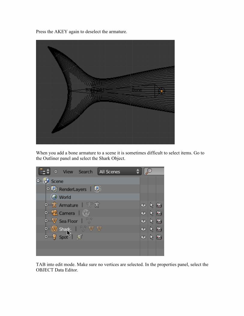
Press the AKEY again to deselect the armature.
When you add a bone armature to a scene it is sometimes difficult to select items. Go to the Outliner panel and select the Shark Object.
TAB into edit mode. Make sure no vertices are selected. In the properties panel, select the OBJECT Data Editor.
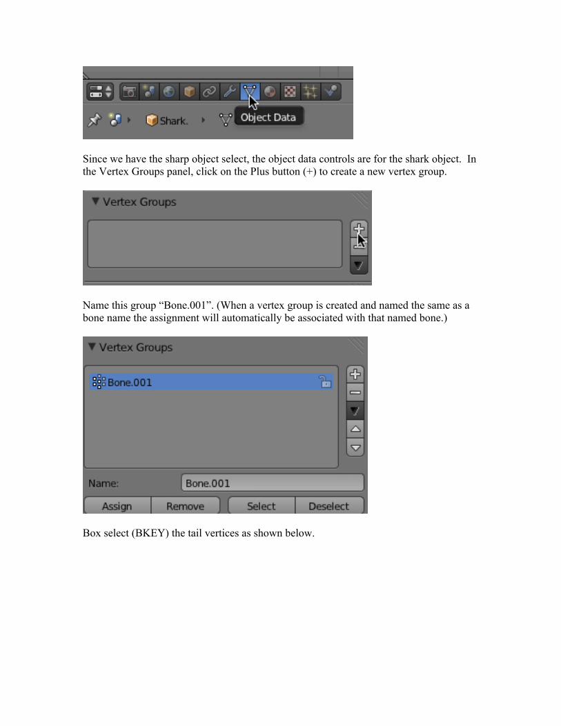
Since we have the sharp object select, the object data controls are for the shark object. In the Vertex Groups panel, click on the Plus button (+) to create a new vertex group.
Name this group “Bone.001”. (When a vertex group is created and named the same as a bone name the assignment will automatically be associated with that named bone.)
Box select (BKEY) the tail vertices as shown below.
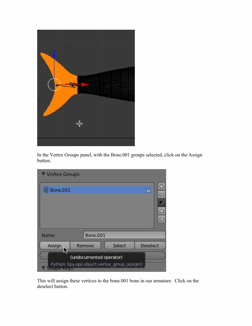
In the Vertex Groups panel, with the Bone.001 groups selected, click on the Assign button.
This will assign these vertices to the bone.001 bone in our armature. Click on the deselect button.
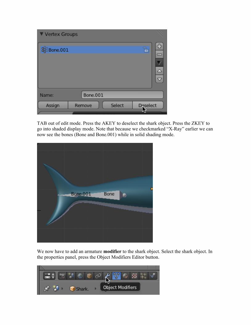
TAB out of edit mode. Press the AKEY to deselect the shark object. Press the ZKEY to go into shaded display mode. Note that because we checkmarked “X-Ray” earlier we can now see the bones (Bone and Bone.001) while in solid shading mode.
We now have to add an armature modifier to the shark object. Select the shark object. In the properties panel, press the Object Modifiers Editor button.
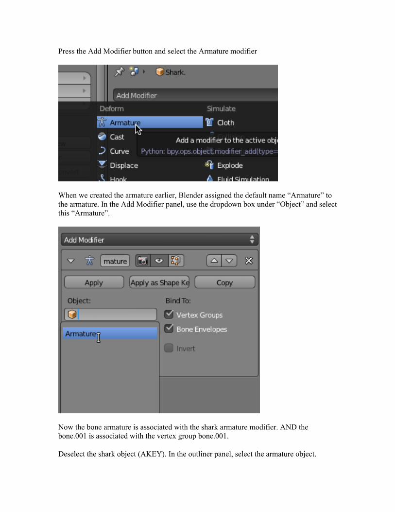
Press the Add Modifier button and select the Armature modifier
When we created the armature earlier, Blender assigned the default name “Armature” to the armature. In the Add Modifier panel, use the dropdown box under “Object” and select this “Armature”.
Now the bone armature is associated with the shark armature modifier. AND the bone.001 is associated with the vertex group bone.001.
Deselect the shark object (AKEY). In the outliner panel, select the armature object.
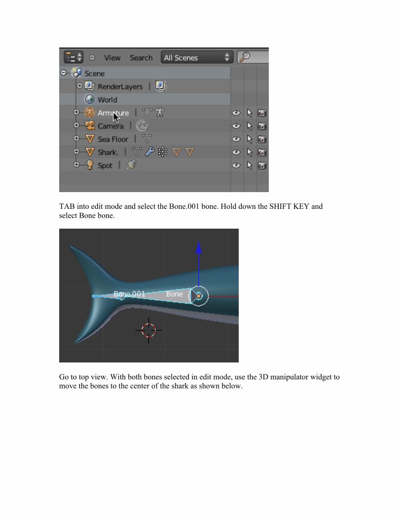
TAB into edit mode and select the Bone.001 bone. Hold down the SHIFT KEY and select Bone bone.
Go to top view. With both bones selected in edit mode, use the 3D manipulator widget to move the bones to the center of the shark as shown below.
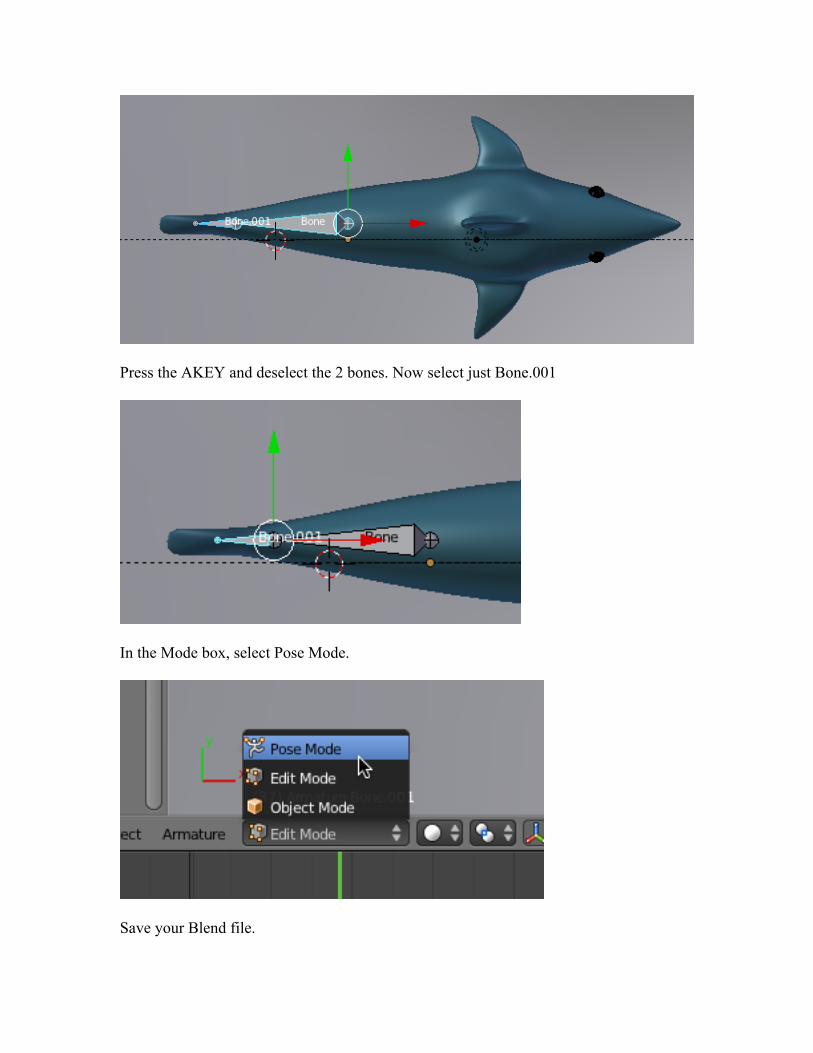
Press the AKEY and deselect the 2 bones. Now select just Bone.001
In the Mode box, select Pose Mode.
Save your Blend file.
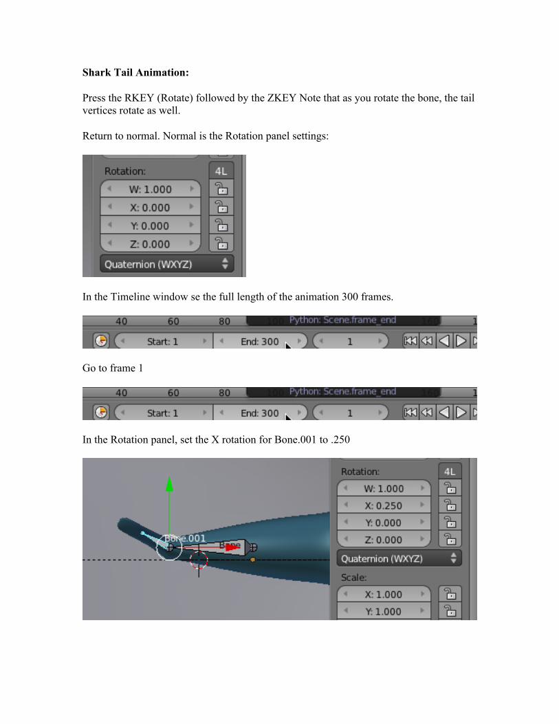
Shark Tail Animation:
Press the RKEY (Rotate) followed by the ZKEY Note that as you rotate the bone, the tail vertices rotate as well.
Return to normal. Normal is the Rotation panel settings:
In the Timeline window se the full length of the animation 300 frames.
Go to frame 1
In the Rotation panel, set the X rotation for Bone.001 to .250
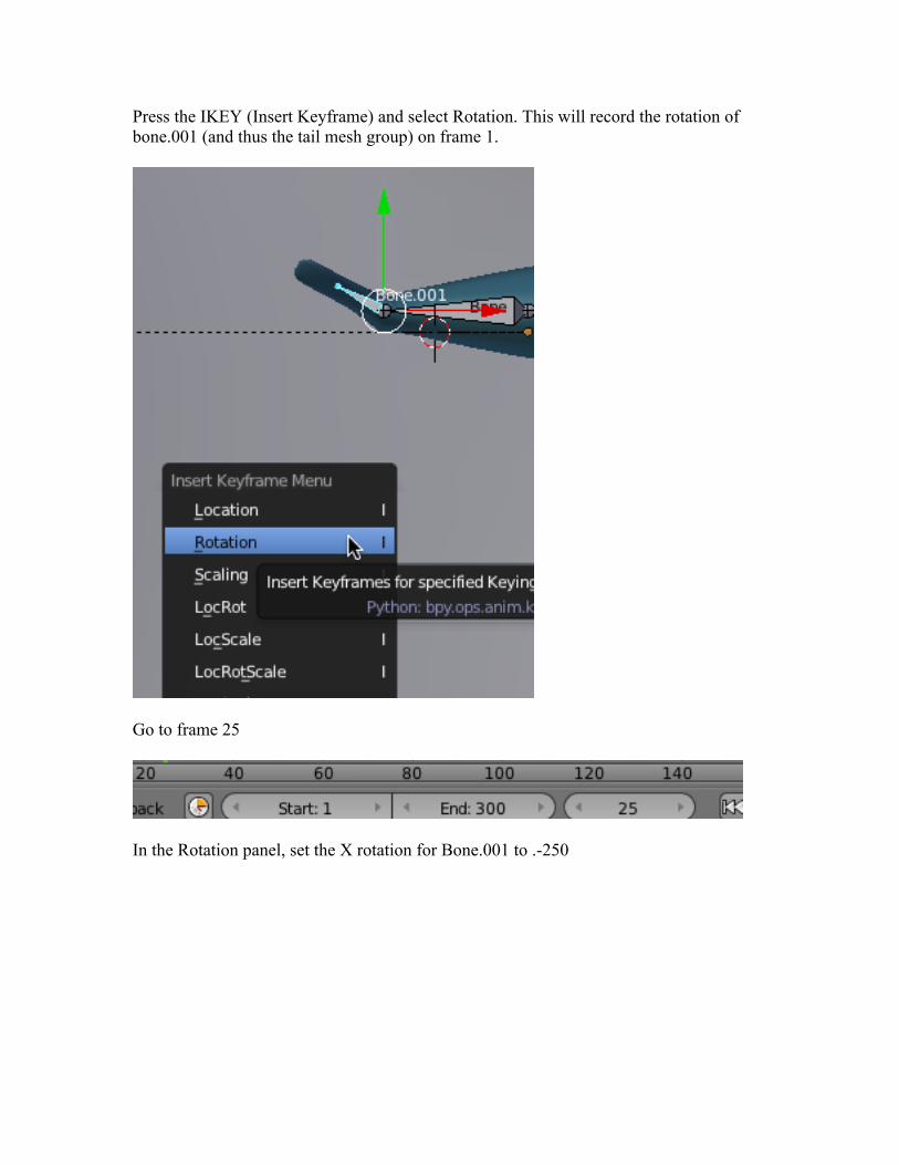
Press the IKEY (Insert Keyframe) and select Rotation. This will record the rotation of bone.001 (and thus the tail mesh group) on frame 1.
Go to frame 25
In the Rotation panel, set the X rotation for Bone.001 to .-250
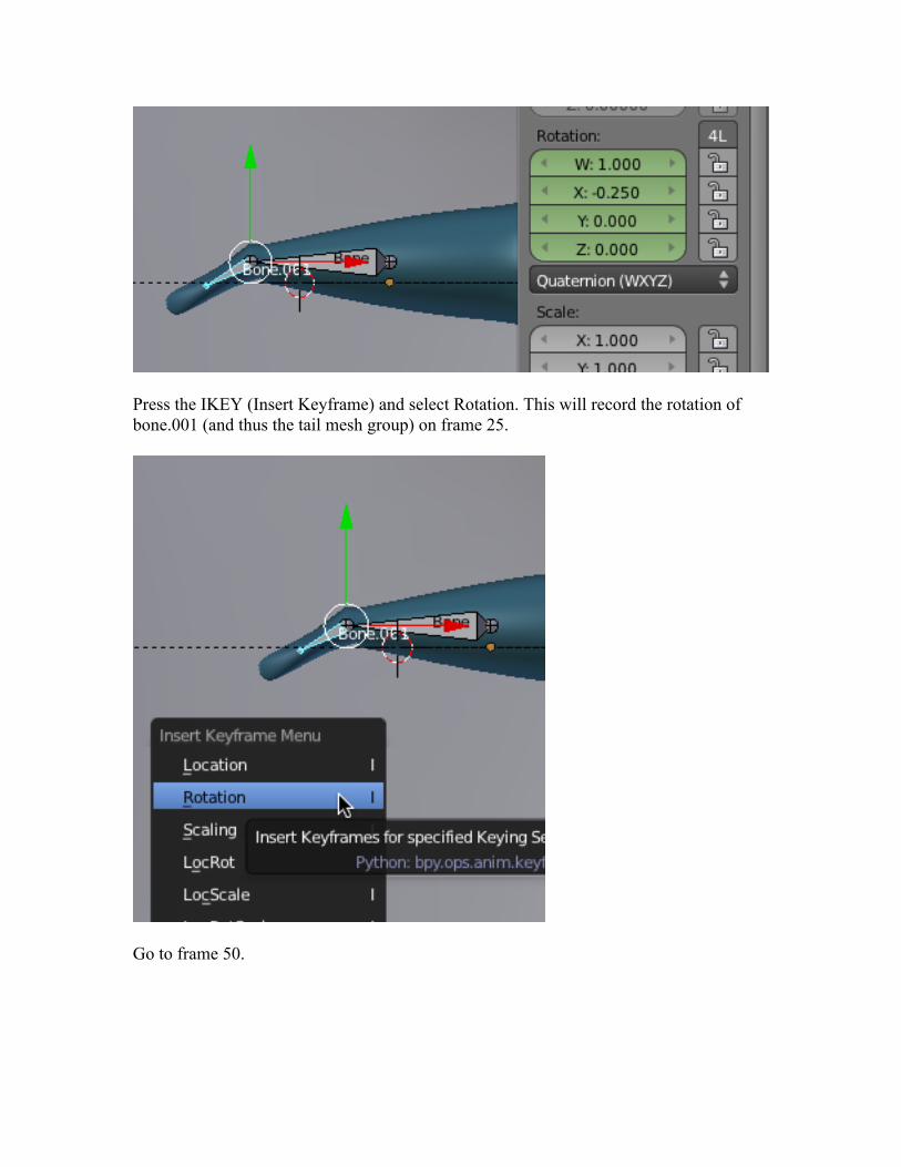
Press the IKEY (Insert Keyframe) and select Rotation. This will record the rotation of bone.001 (and thus the tail mesh group) on frame 25.
Go to frame 50.
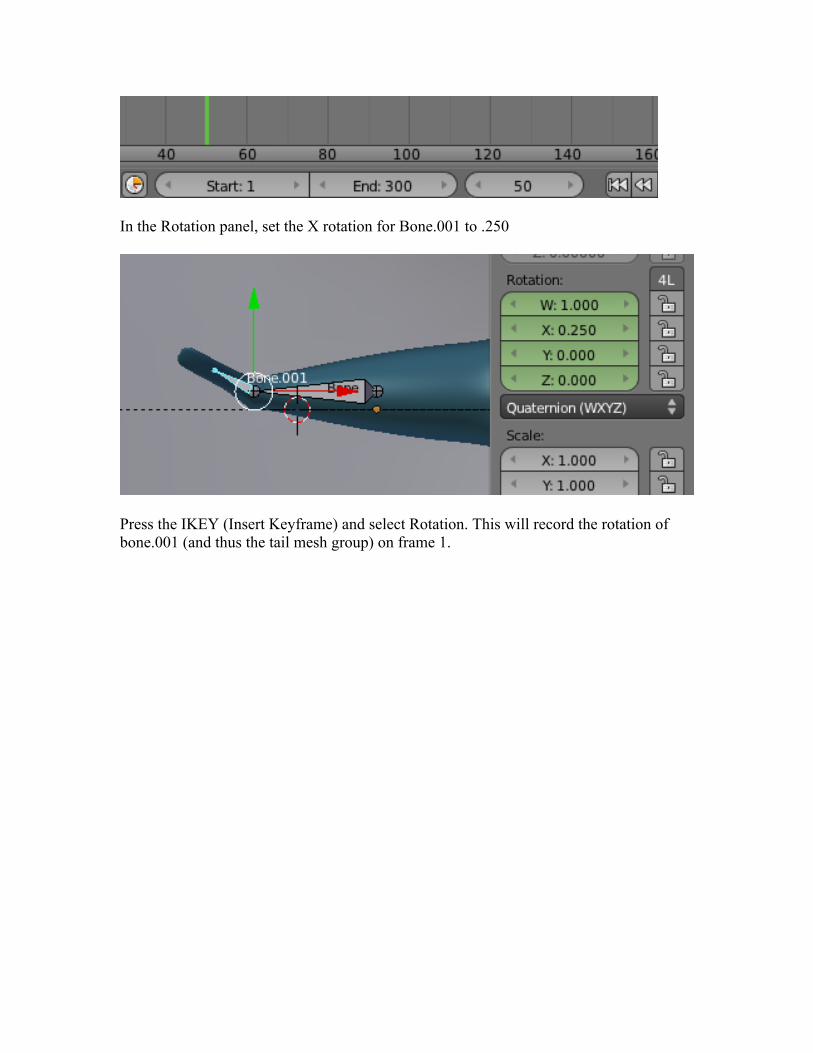
In the Rotation panel, set the X rotation for Bone.001 to .250
Press the IKEY (Insert Keyframe) and select Rotation. This will record the rotation of bone.001 (and thus the tail mesh group) on frame 1.
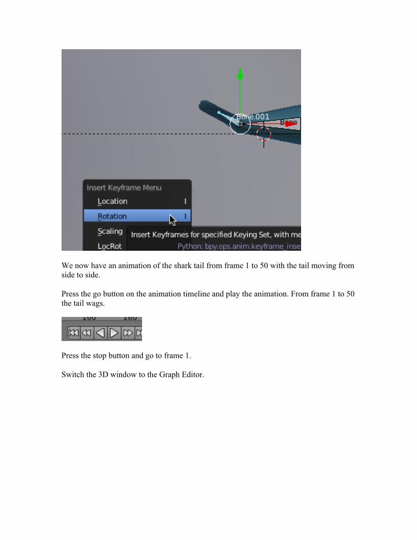
We now have an animation of the shark tail from frame 1 to 50 with the tail moving from side to side.
Press the go button on the animation timeline and play the animation. From frame 1 to 50 the tail wags.
Press the stop button and go to frame 1.
Switch the 3D window to the Graph Editor.
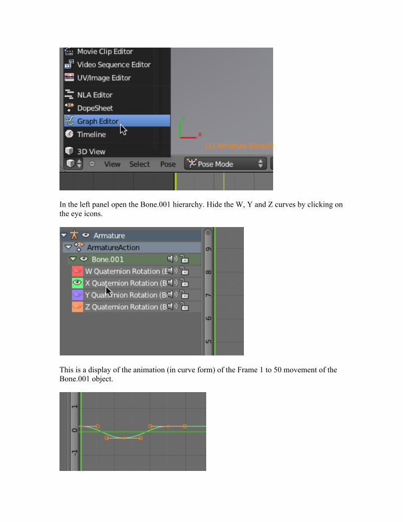
In the left panel open the Bone.001 hierarchy. Hide the W, Y and Z curves by clicking on the eye icons.
This is a display of the animation (in curve form) of the Frame 1 to 50 movement of the Bone.001 object.
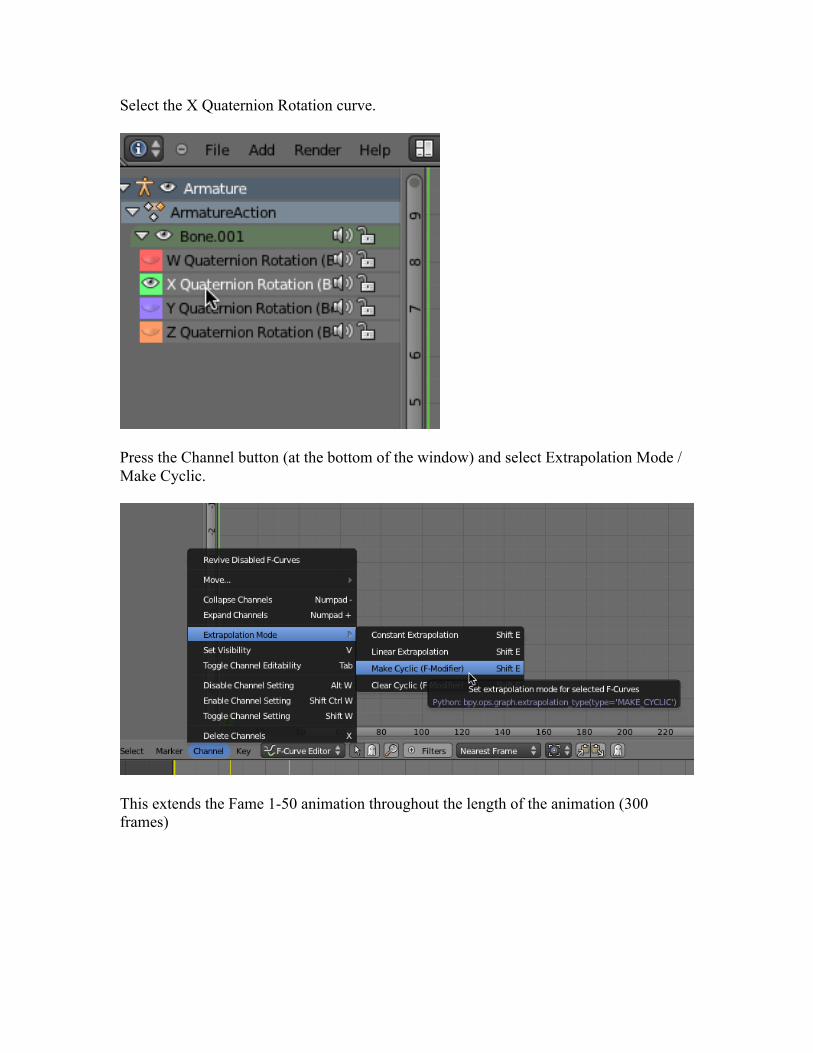
Select the X Quaternion Rotation curve.
Press the Channel button (at the bottom of the window) and select Extrapolation Mode / Make Cyclic.
This extends the Fame 1-50 animation throughout the length of the animation (300 frames)
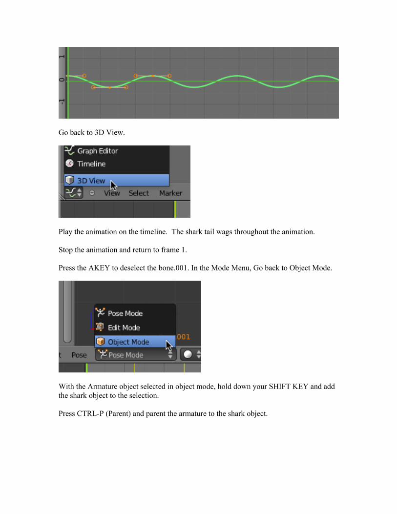
Go back to 3D View.
Play the animation on the timeline. The shark tail wags throughout the animation.
Stop the animation and return to frame 1.
Press the AKEY to deselect the bone.001. In the Mode Menu, Go back to Object Mode.
With the Armature object selected in object mode, hold down your SHIFT KEY and add the shark object to the selection.
Press CTRL-P (Parent) and parent the armature to the shark object.
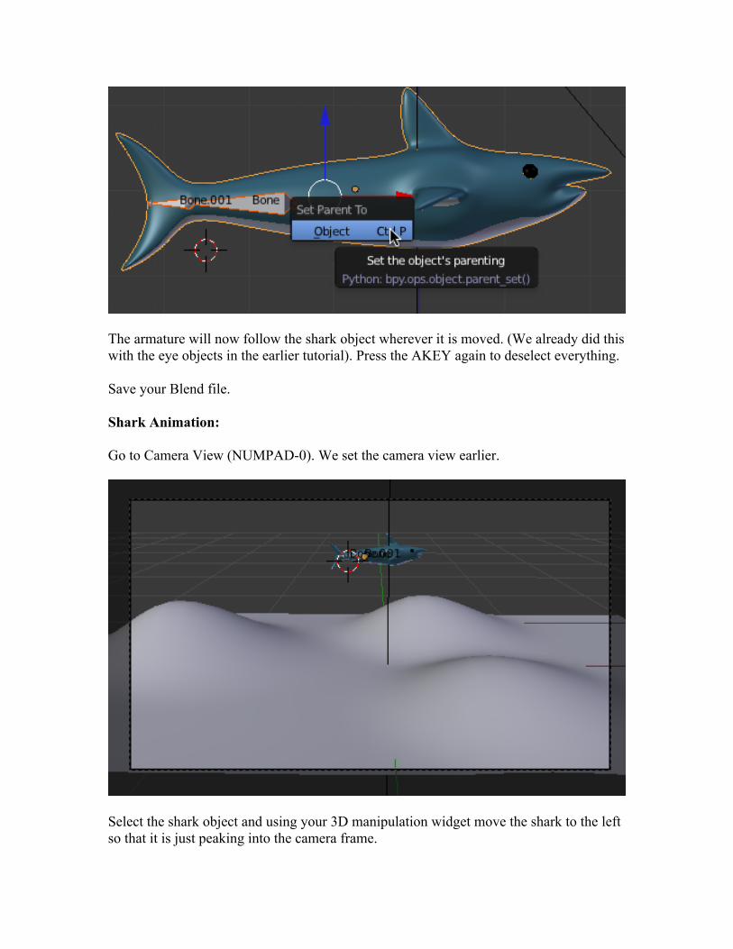
The armature will now follow the shark object wherever it is moved. (We already did this with the eye objects in the earlier tutorial). Press the AKEY again to deselect everything.
Save your Blend file.
Shark Animation:
Go to Camera View (NUMPAD-0). We set the camera view earlier.
Select the shark object and using your 3D manipulation widget move the shark to the left so that it is just peaking into the camera frame.
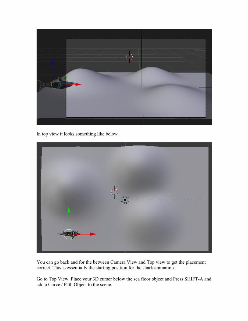
In top view it looks something like below.
You can go back and for the between Camera View and Top view to get the placement correct. This is essentially the starting position for the shark animation.
Go to Top View. Place your 3D cursor below the sea floor object and Press SHIFT-A and add a Curve / Path Object to the scene.
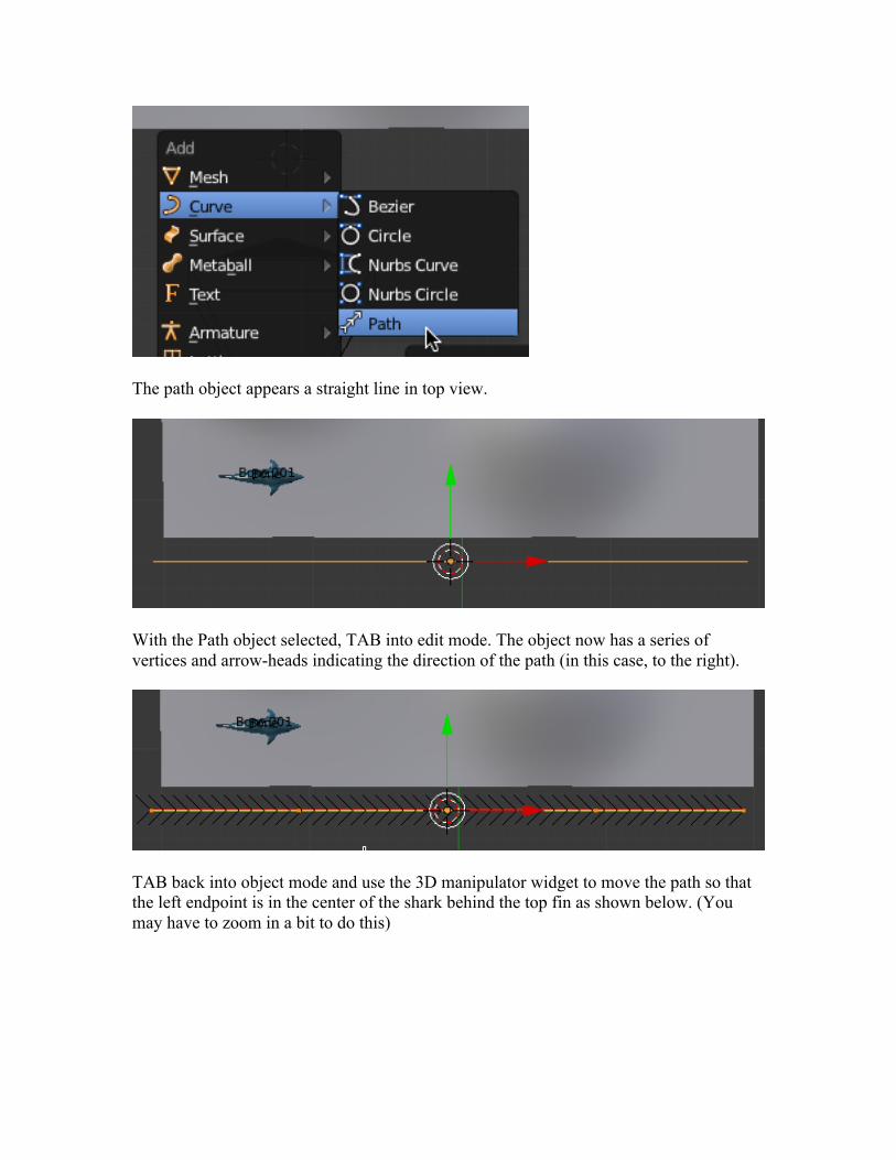
The path object appears a straight line in top view.
With the Path object selected, TAB into edit mode. The object now has a series of vertices and arrow-heads indicating the direction of the path (in this case, to the right).
TAB back into object mode and use the 3D manipulator widget to move the path so that the left endpoint is in the center of the shark behind the top fin as shown below. (You may have to zoom in a bit to do this)
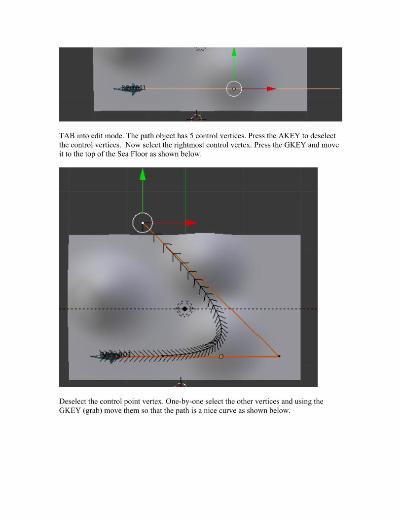
TAB into edit mode. The path object has 5 control vertices. Press the AKEY to deselect the control vertices. Now select the rightmost control vertex. Press the GKEY and move it to the top of the Sea Floor as shown below.
Deselect the control point vertex. One-by-one select the other vertices and using the GKEY (grab) move them so that the path is a nice curve as shown below.
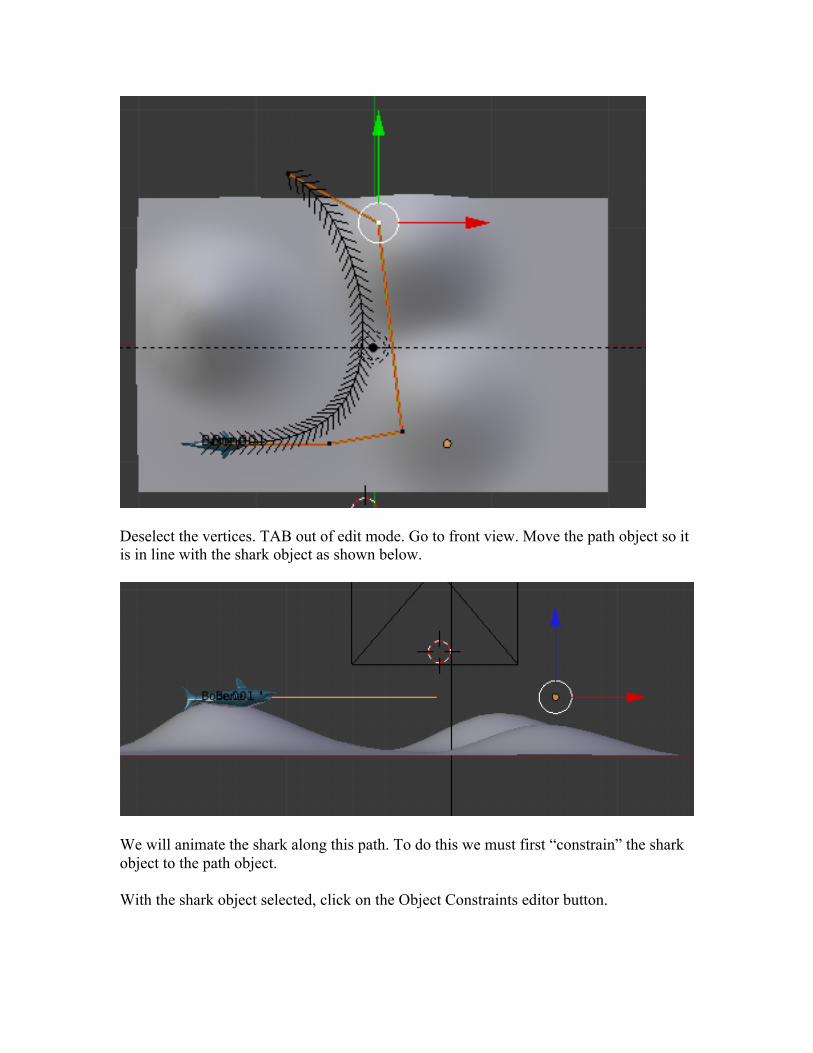
Deselect the vertices. TAB out of edit mode. Go to front view. Move the path object so it is in line with the shark object as shown below.
We will animate the shark along this path. To do this we must first “constrain” the shark object to the path object.
With the shark object selected, click on the Object Constraints editor button.
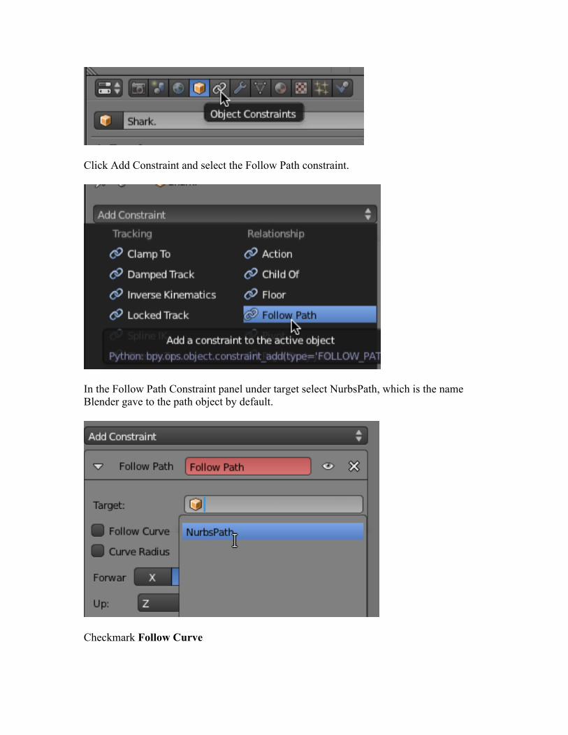
Click Add Constraint and select the Follow Path constraint.
In the Follow Path Constraint panel under target select NurbsPath, which is the name Blender gave to the path object by default.
Checkmark Follow Curve
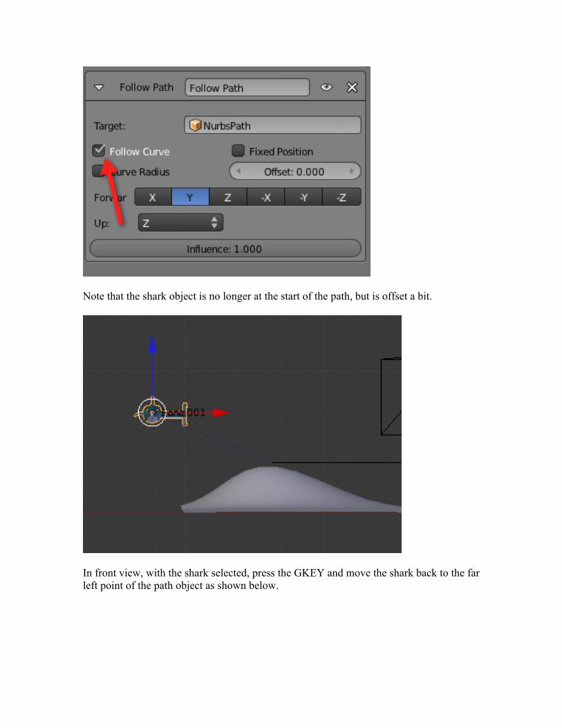
Note that the shark object is no longer at the start of the path, but is offset a bit.
In front view, with the shark selected, press the GKEY and move the shark back to the far left point of the path object as shown below.
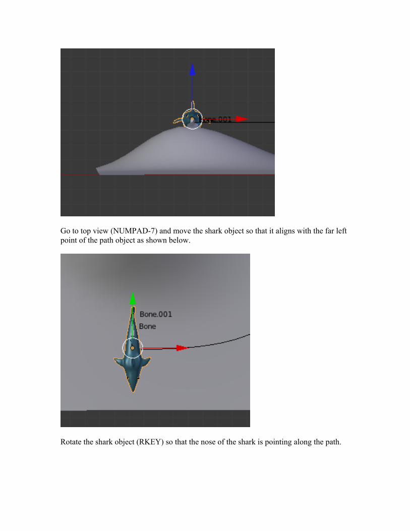
Go to top view (NUMPAD-7) and move the shark object so that it aligns with the far left point of the path object as shown below.
Rotate the shark object (RKEY) so that the nose of the shark is pointing along the path.
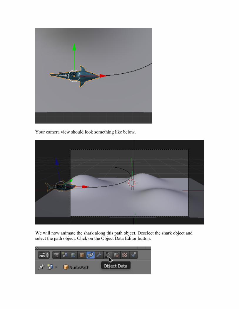
Your camera view should look something like below.
We will now animate the shark along this path object. Deselect the shark object and select the path object. Click on the Object Data Editor button.
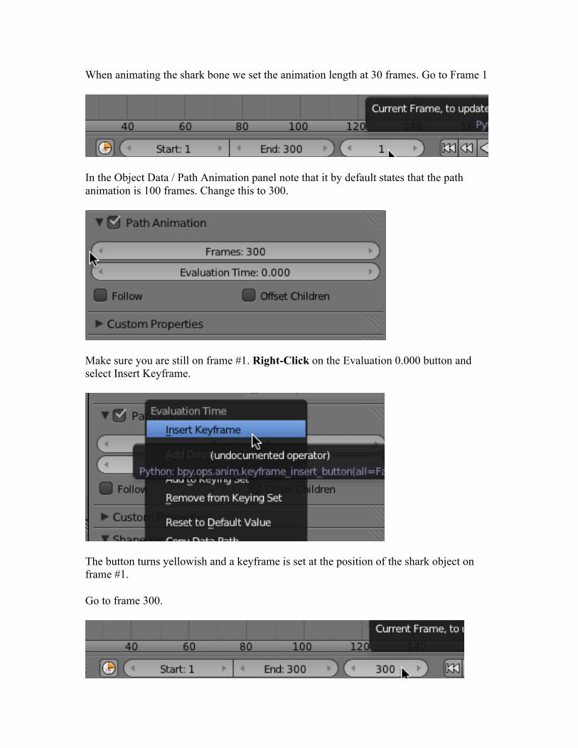
When animating the shark bone we set the animation length at 30 frames. Go to Frame 1
In the Object Data / Path Animation panel note that it by default states that the path animation is 100 frames. Change this to 300.
Make sure you are still on frame #1. Right-Click on the Evaluation 0.000 button and select Insert Keyframe.
The button turns yellowish and a keyframe is set at the position of the shark object on frame #1.
Go to frame 300.
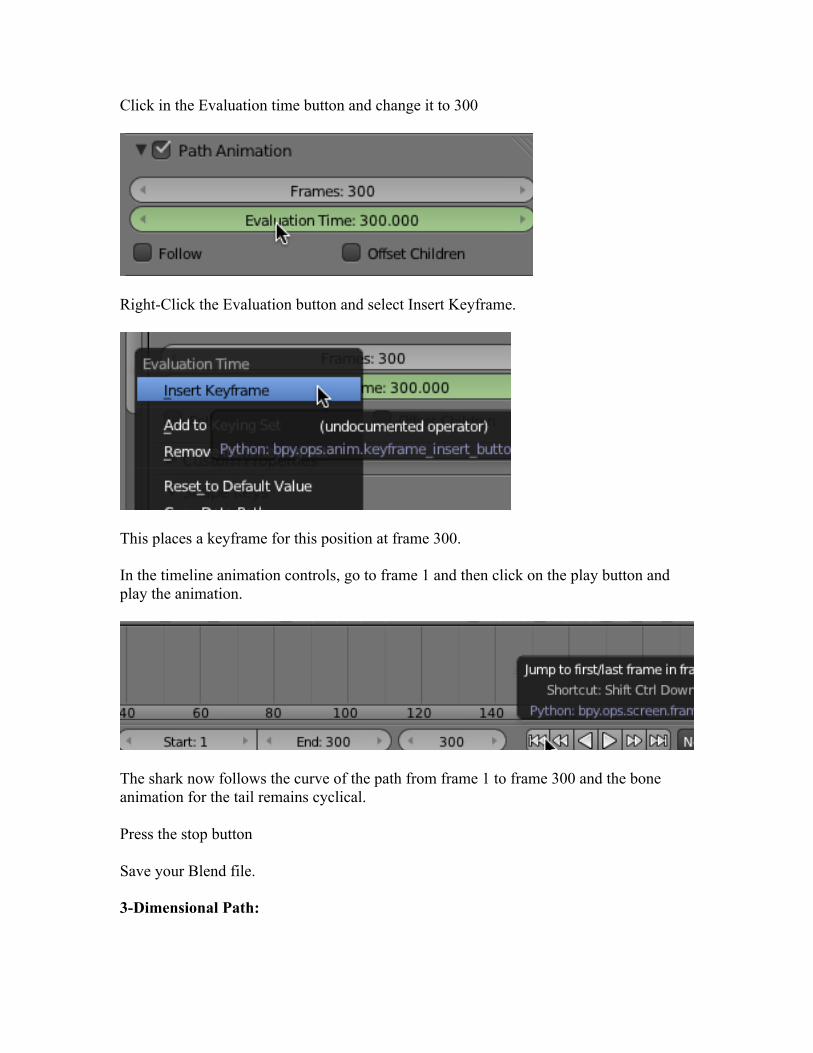
Click in the Evaluation time button and change it to 300
Right-Click the Evaluation button and select Insert Keyframe.
This places a keyframe for this position at frame 300.
In the timeline animation controls, go to frame 1 and then click on the play button and play the animation.
The shark now follows the curve of the path from frame 1 to frame 300 and the bone animation for the tail remains cyclical.
Press the stop button
Save your Blend file.
3-Dimensional Path:
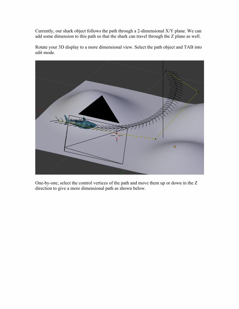
Currently, our shark object follows the path through a 2-dimensional X/Y plane. We can add some dimension to this path so that the shark can travel through the Z plane as well.
Rotate your 3D display to a more dimensional view. Select the path object and TAB into edit mode.
One-by-one, select the control vertices of the path and move them up or down in the Z direction to give a more dimensional path as shown below.
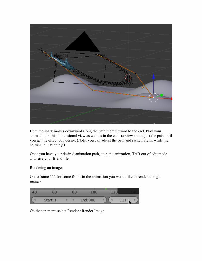
Here the shark moves downward along the path them upward to the end. Play your animation in this dimensional view as well as in the camera view and adjust the path until you get the effect you desire. (Note: you can adjust the path and switch views while the animation is running.)
Once you have your desired animation path, stop the animation, TAB out of edit mode and save your Blend file.
Rendering an image:
Go to frame 111 (or some frame in the animation you would like to render a single image)
On the top menu select Render / Render Image
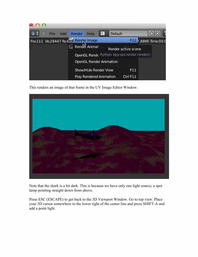
This renders an image of that frame in the UV Image Editor Window.
Note that the shark is a bit dark. This is because we have only one light source; a spot lamp pointing straight down from above.
Press ESC (ESCAPE) to get back to the 3D Viewport Window. Go to top view. Place your 3D cursor somewhere to the lower right of the center line and press SHIFT-A and add a point light.
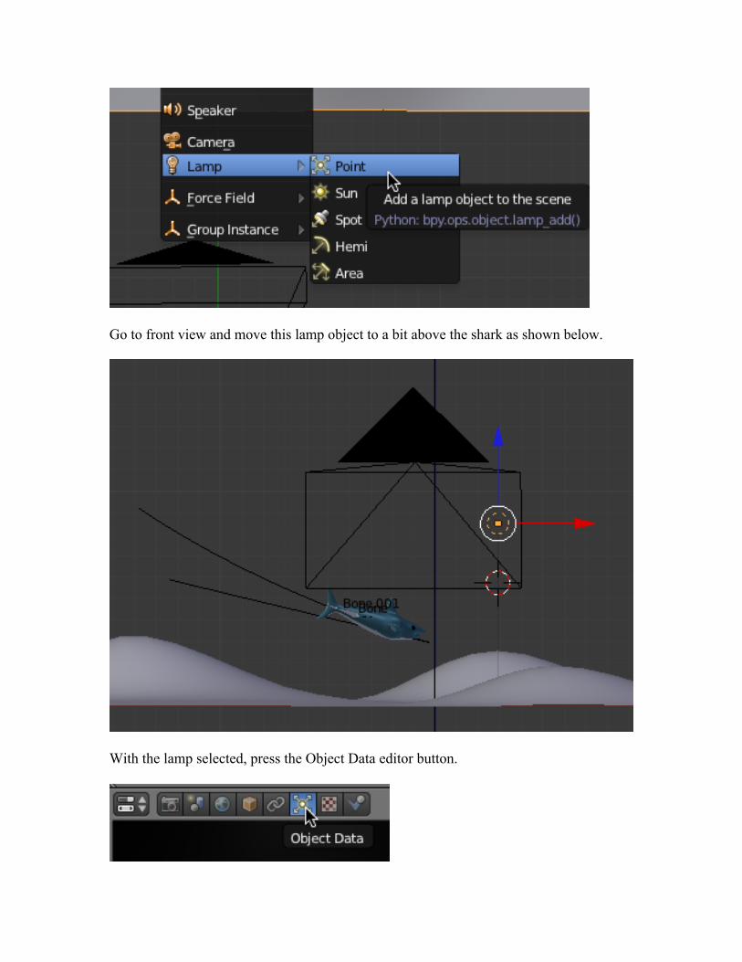
Go to front view and move this lamp object to a bit above the shark as shown below.
With the lamp selected, press the Object Data editor button.
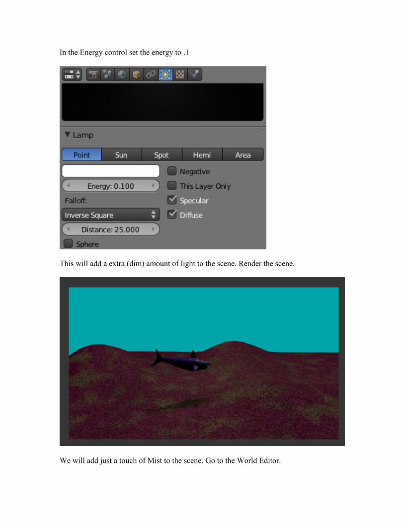
In the Energy control set the energy to .1
This will add a extra (dim) amount of light to the scene. Render the scene.
We will add just a touch of Mist to the scene. Go to the World Editor.
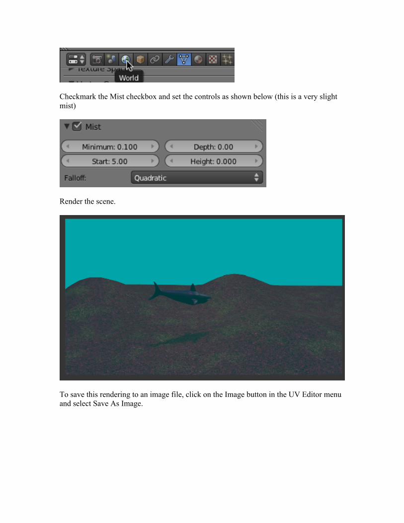
Checkmark the Mist checkbox and set the controls as shown below (this is a very slight mist)
Render the scene.
To save this rendering to an image file, click on the Image button in the UV Editor menu and select Save As Image.
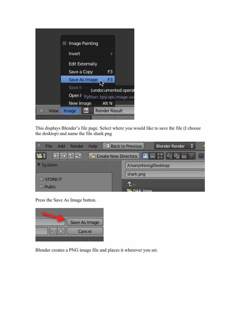
This displays Blender’s file page. Select where you would like to save the file (I choose the desktop) and name the file shark.png
Press the Save As Image button.
Blender creates a PNG image file and places it wherever you set.
Save your Blend file.
Render Animation Video:
In addition to rendering a still image we can also render the 300 frame animation and save it to our computer as a Video file (MPEG).
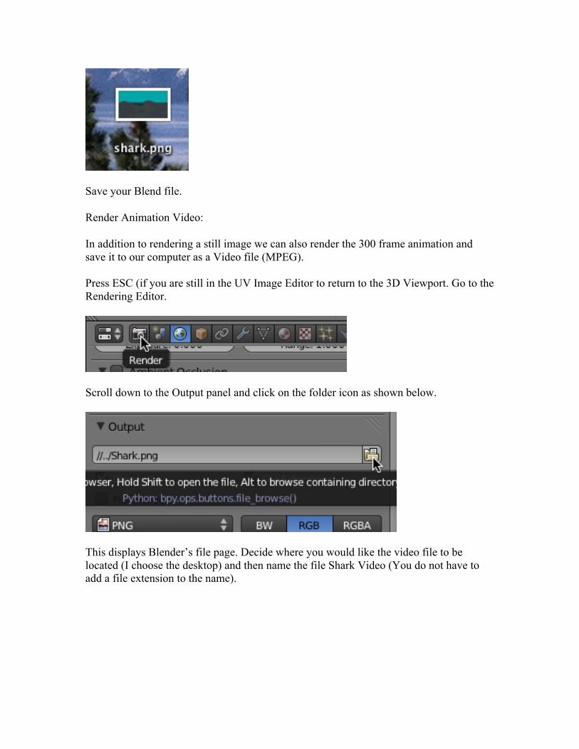
Press ESC (if you are still in the UV Image Editor to return to the 3D Viewport. Go to the Rendering Editor.
Scroll down to the Output panel and click on the folder icon as shown below.
This displays Blender’s file page. Decide where you would like the video file to be located (I choose the desktop) and then name the file Shark Video (You do not have to add a file extension to the name).
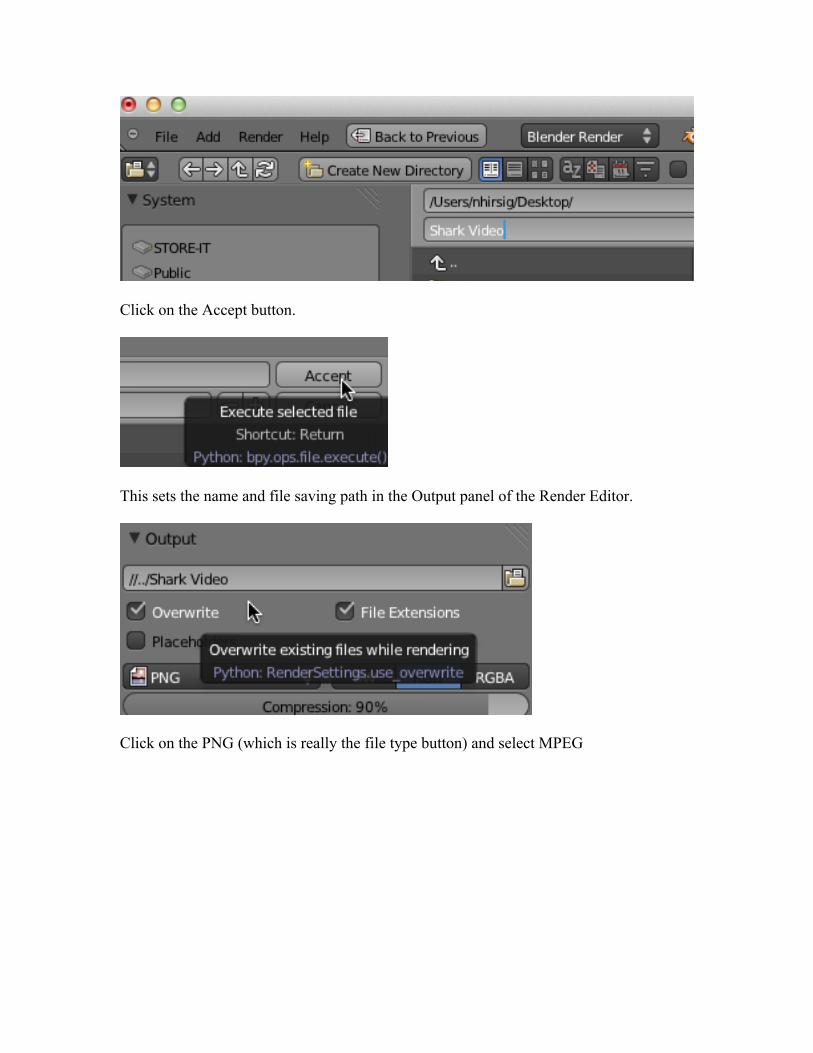
Click on the Accept button.
This sets the name and file saving path in the Output panel of the Render Editor.
Click on the PNG (which is really the file type button) and select MPEG
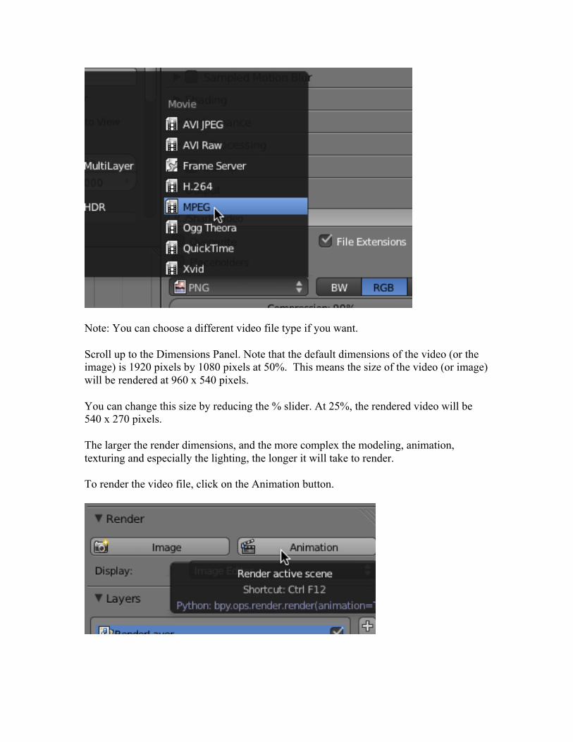
Note: You can choose a different video file type if you want.
Scroll up to the Dimensions Panel. Note that the default dimensions of the video (or the image) is 1920 pixels by 1080 pixels at 50%. This means the size of the video (or image) will be rendered at 960 x 540 pixels.
You can change this size by reducing the % slider. At 25%, the rendered video will be 540 x 270 pixels.
The larger the render dimensions, and the more complex the modeling, animation, texturing and especially the lighting, the longer it will take to render.
To render the video file, click on the Animation button.
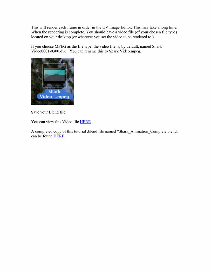
This will render each frame in order in the UV Image Editor. This may take a long time. When the rendering is complete. You should have a video file (of your chosen file type) located on your desktop (or wherever you set the video to be rendered to.)
If you choose MPEG as the file type, the video file is, by default, named Shark Video0001-0300.dvd. You can rename this to Shark Video.mpeg.
Save your Blend file.
You can view this Video file HERE.
A completed copy of this tutorial .blend file named “Shark_Animation_Complete.blend: can be found HERE.


![Blender in Research & Education · Blender in Research •Blender as a modelling tool •Projects: •Radio Wave Propagation •Global Illumination •Character Animation [1] Wave](https://static.fdocuments.us/doc/165x107/5e986a71843c4f2f7349f3ad/blender-in-research-education-blender-in-research-ablender-as-a-modelling.jpg)