Revolution in gear milling: uP-Gear Technology - Interempresas
UNIT – 3
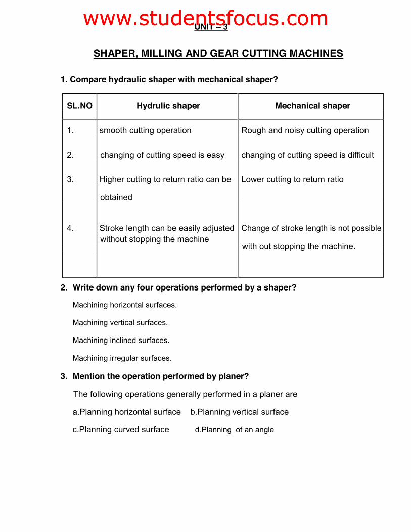
SHAPER, MILLING AND GEAR CUTTING MACHINES 1. Compare hydraulic shaper with mechanical shaper?
SL.NO Hydrulic shaper Mechanical shaper
1. smooth cutting operation Rough and noisy cutting operation
2. changing of cutting speed is easy changing of cutting speed is difficult
3. Higher cutting to return ratio can be Lower cutting to return ratio
obtained
4. Stroke length can be easily adjusted Change of stroke length is not possible
without stopping the machine with out stopping the machine.
2. Write down any four operations performed by a shaper?
Machining horizontal surfaces.
Machining vertical surfaces.
Machining inclined surfaces.
Machining irregular surfaces. 3. Mention the operation performed by planer?
The following operations generally performed in a planer are
a.Planning horizontal surface b.Planning vertical surface
c.Planning curved surface d.Planning of an angle
www.studentsfocus.comwww.studentsfocus.com
4. What is the function of clapper block in a planer?
During cutting stroke, the tool block fits inside the clapper block rigidly.
During the return stroke, the tool block lifts out of the clapper block to avoid
rubbing of the tool on the job.
5. State the difference between a vertical shaper and a slotter?
vertical shaper slotter
1. vertical shapers generally fitted 1.The slides are fitted
with rotary table to machine
curved surfaces
2. Rotary table along with tools will 2.slides will move to perform
remove. slotting.
3. vertical shaper is not fixed in the 3. slotter is fixed in the vertical
vertical plane plane.
6. What are the common work holding devices used on milling
machines? a.„v‟ blocks.
b.machine vises.
c .milling fixtures.
d.Dividing heads
www.studentsfocus.comwww.studentsfocus.com
7. What is a shell mill?
A shell mill is a large type of face or end mill that mounts onto an arbor,
rather than having an integral shank. Typicaly, there is a hollow or recess in
the center of the shell for mounting hardware onto a separate arbor. 8. What is meant by up-milling and down milling?
In up milling, cutters rotates opposites to the direction of a feed of the work
piece whereas in down milling, the cutter rotates in the same direction of
travel of the workpiece.
9. What are the differences between up milling and down milling?
SL.NO EVENT OF UP MILLING DOWN MILLING
OPERATION
1. Direction of Cutter rotates against the Cutter rotates in the
Travel direction of travel of same direction of
workpiece. travel of workpiece
Chip
Minimum at the
2. beginning
of cut Maximum at the
thickness beginnining Greeches
Greeches max when the min at terminates
3. cut terminates.
cutting force Decreases from max
Increases from zero to
to zero per tooth.
max per tooth
www.studentsfocus.comwww.studentsfocus.com
10. What is thread milling?
A thread milling has no chamfer. The mill is inserted into the hole along the
axis of the spindle, deep enough to produce full thread depth required
11. write down the rule for gear ratio in differential indexing
Rule for gear ratio in differential
indexing: Gear ratio = (A-N)/A
A- Selected no which can be indexed by plain indexing and
approximately equal to N.
N- Required no. of divisions to be indexed. 12. How do specify radial drilling machine?
A drilling machine is specified by the job following items.
1. Maximum size of the drill in mm that the machine can be operates.
2. Table size of maximum dimension of a job can mount on a table in
square meter.
3. maximum spindle speed and range of spindle speeds in r.p.m 13. Write down any four operations that can be performed in a drilling machine?
1. Drilling
2. counter sinking
3. Tapping
4. Reaming. 14. What is meant by “sensitive hand feed”?
In drilling machines, manual sensing of the hand does feeding of the tools
towards the work piece. it is called as sensitive hand feed
www.studentsfocus.comwww.studentsfocus.com
15. What is broaching?
Broaching is a process of machining a surface with a special multipoint cutting
tool called “broach” which has successively higher cutting edges in a fixed
path. 16. Why is sawing a commonly used process?
1. Easy handling of machines and spindle construction
2. Fast operation and cost of machinery is less
www.studentsfocus.comwww.studentsfocus.com
UNIT III
SHAPER, MILLING AND GEAR CUTTING MACHINES
PART - B
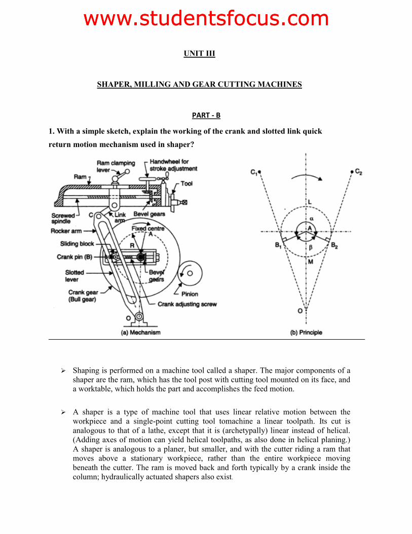
1. With a simple sketch, explain the working of the crank and slotted link quick return motion mechanism used in shaper?
¾ Shaping is performed on a machine tool called a shaper. The major components of a shaper are the ram, which has the tool post with cutting tool mounted on its face, and a worktable, which holds the part and accomplishes the feed motion.
¾ A shaper is a type of machine tool that uses linear relative motion between the workpiece and a single-point cutting tool tomachine a linear toolpath. Its cut is analogous to that of a lathe, except that it is (archetypally) linear instead of helical. (Adding axes of motion can yield helical toolpaths, as also done in helical planing.) A shaper is analogous to a planer, but smaller, and with the cutter riding a ram that moves above a stationary workpiece, rather than the entire workpiece moving beneath the cutter. The ram is moved back and forth typically by a crank inside the column; hydraulically actuated shapers also exist.
www.studentsfocus.comwww.studentsfocus.com
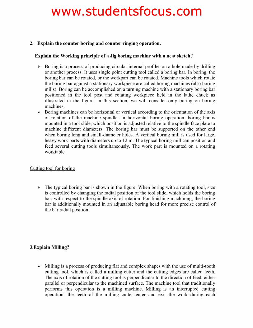
2. Explain the counter boring and counter ringing operation.
Explain the Working principle of a Jig boring machine with a neat sketch?
¾ Boring is a process of producing circular internal profiles on a hole made by drilling or another process. It uses single point cutting tool called a boring bar. In boring, the boring bar can be rotated, or the workpart can be rotated. Machine tools which rotate the boring bar against a stationary workpiece are called boring machines (also boring mills). Boring can be accomplished on a turning machine with a stationary boring bar positioned in the tool post and rotating workpiece held in the lathe chuck as illustrated in the figure. In this section, we will consider only boring on boring machines.
¾ Boring machines can be horizontal or vertical according to the orientation of the axis of rotation of the machine spindle. In horizontal boring operation, boring bar is mounted in a tool slide, which position is adjusted relative to the spindle face plate to machine different diameters. The boring bar must be supported on the other end when boring long and small-diameter holes. A vertical boring mill is used for large, heavy work parts with diameters up to 12 m. The typical boring mill can position and feed several cutting tools simultaneously. The work part is mounted on a rotating worktable.
Cutting tool for boring
¾ The typical boring bar is shown in the figure. When boring with a rotating tool, size is controlled by changing the radial position of the tool slide, which holds the boring bar, with respect to the spindle axis of rotation. For finishing machining, the boring bar is additionally mounted in an adjustable boring head for more precise control of the bar radial position.
3.Explain Milling?
¾ Milling is a process of producing flat and complex shapes with the use of multi-tooth cutting tool, which is called a milling cutter and the cutting edges are called teeth. The axis of rotation of the cutting tool is perpendicular to the direction of feed, either parallel or perpendicular to the machined surface. The machine tool that traditionally performs this operation is a milling machine. Milling is an interrupted cutting operation: the teeth of the milling cutter enter and exit the work during each
www.studentsfocus.comwww.studentsfocus.com
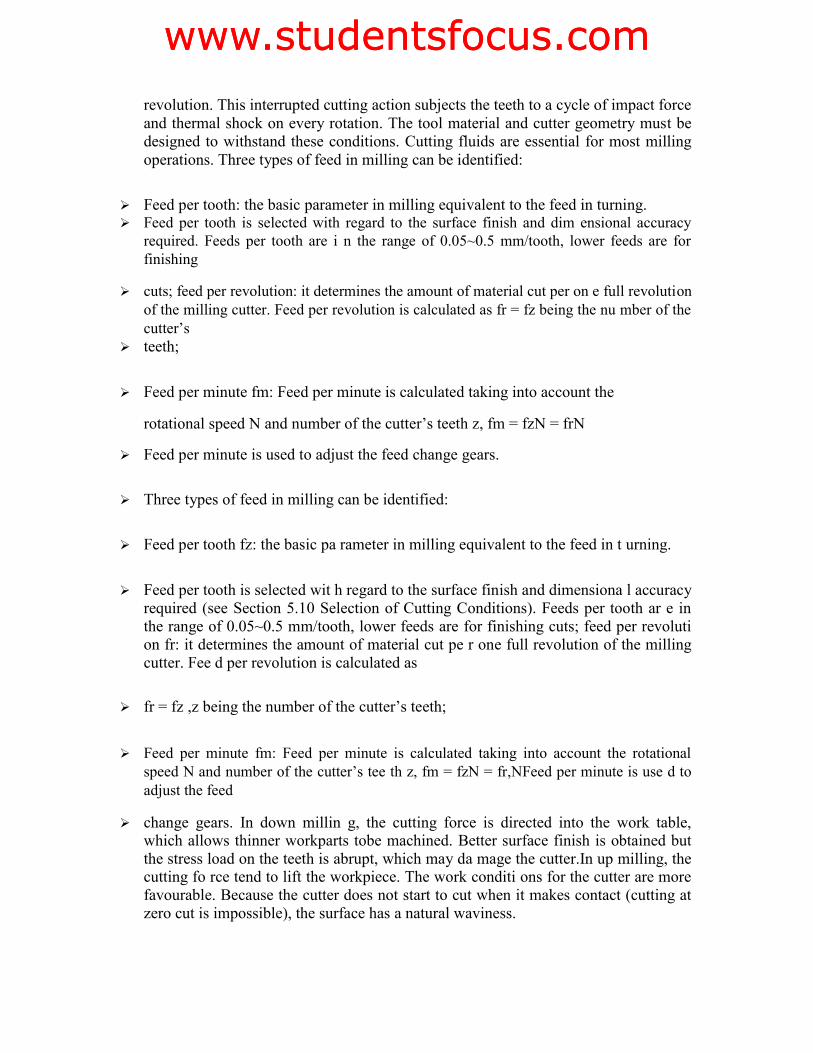
revolution. This interrupted cutting action subjects the teeth to a cycle of impact force and thermal shock on every rotation. The tool material and cutter geometry must be designed to withstand these conditions. Cutting fluids are essential for most milling operations. Three types of feed in milling can be identified:
¾ Feed per tooth: the basic parameter in milling equivalent to the feed in turning. ¾ Feed per tooth is selected with regard to the surface finish and dim ensional accuracy
required. Feeds per tooth are i n the range of 0.05~0.5 mm/tooth, lower feeds are for finishing
¾ cuts; feed per revolution: it determines the amount of material cut per on e full revolution of the milling cutter. Feed per revolution is calculated as fr = fz being the nu mber of the cutter’s
¾ teeth;
¾ Feed per minute fm: Feed per minute is calculated taking into account the
rotational speed N and number of the cutter’s teeth z, fm = fzN = frN
¾ Feed per minute is used to adjust the feed change gears.
¾ Three types of feed in milling can be identified:
¾ Feed per tooth fz: the basic pa rameter in milling equivalent to the feed in t urning.
¾ Feed per tooth is selected wit h regard to the surface finish and dimensiona l accuracy required (see Section 5.10 Selection of Cutting Conditions). Feeds per tooth ar e in the range of 0.05~0.5 mm/tooth, lower feeds are for finishing cuts; feed per revoluti on fr: it determines the amount of material cut pe r one full revolution of the milling cutter. Fee d per revolution is calculated as
¾ fr = fz ,z being the number of the cutter’s teeth;
¾ Feed per minute fm: Feed per minute is calculated taking into account the rotational speed N and number of the cutter’s tee th z, fm = fzN = fr,NFeed per minute is use d to adjust the feed
¾ change gears. In down millin g, the cutting force is directed into the work table, which allows thinner workparts tobe machined. Better surface finish is obtained but the stress load on the teeth is abrupt, which may da mage the cutter.In up milling, the cutting fo rce tend to lift the workpiece. The work conditi ons for the cutter are more favourable. Because the cutter does not start to cut when it makes contact (cutting at zero cut is impossible), the surface has a natural waviness.
www.studentsfocus.comwww.studentsfocus.com
Milling Operations
Owing to the variety of shapes possible and its high production rates, m illing is one of the most versatile and widely used machining operations. The geometric form created by milling fall into three major groups: P lane surfaces: the surface is linear in all thre e dimensions. The simplest and most convenient type of surface;
Two-dimensional surfaces: th e shape of the surface changes in the direc tion of two of the axes and is linear along the third axis.
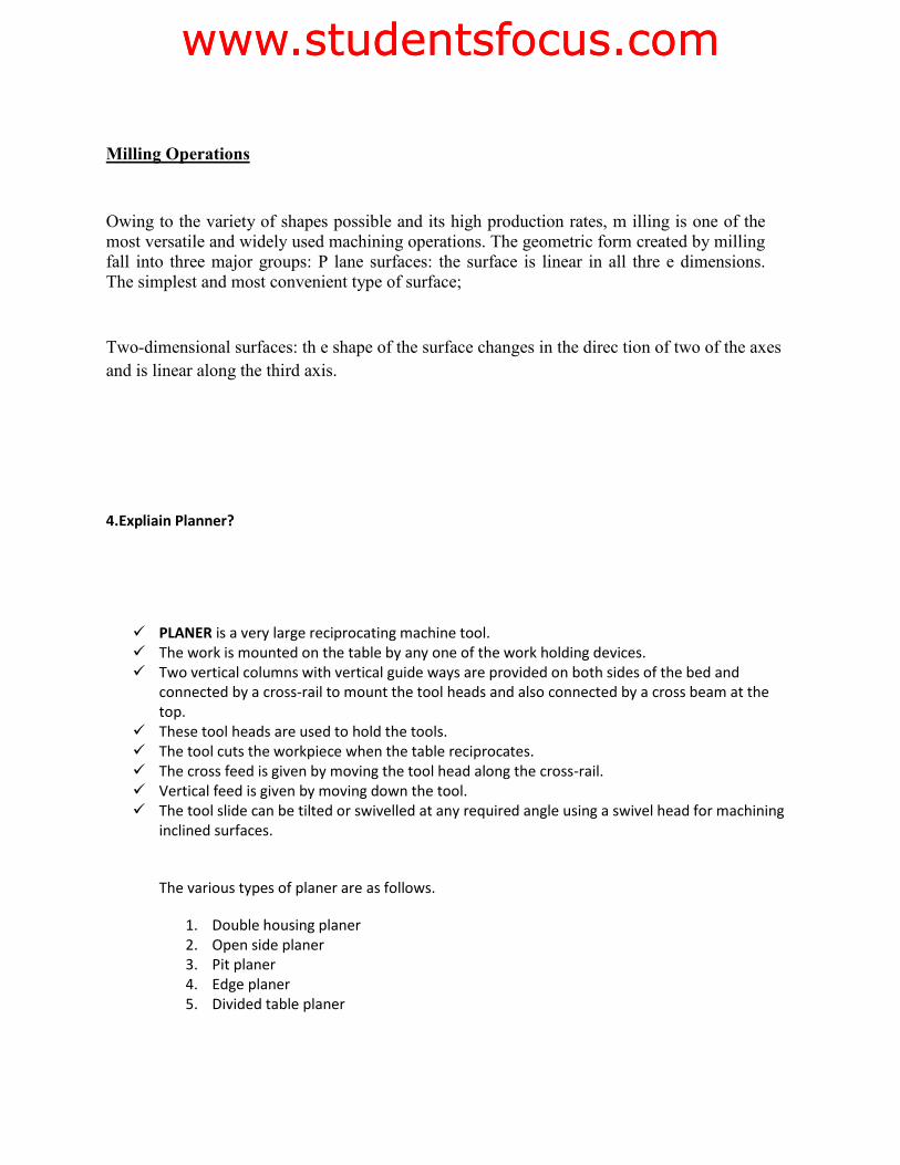
4.Expliain Planner?
9 PLANER is a very large reciprocating machine tool. 9 The work is mounted on the table by any one of the work holding devices. 9 Two vertical columns with vertical guide ways are provided on both sides of the bed and
connected by a cross-rail to mount the tool heads and also connected by a cross beam at the top.
9 These tool heads are used to hold the tools. 9 The tool cuts the workpiece when the table reciprocates. 9 The cross feed is given by moving the tool head along the cross-rail. 9 Vertical feed is given by moving down the tool. 9 The tool slide can be tilted or swivelled at any required angle using a swivel head for machining
inclined surfaces.
The various types of planer are as follows.
1. Double housing planer 2. Open side planer 3. Pit planer 4. Edge planer 5. Divided table planer
www.studentsfocus.comwww.studentsfocus.com
5.Explain Specification of Planer?
9 The distance between two columns 9 Stroke length of the planer 9 Radial distance between the top of the table and the bottom most position of the cross rail 9 Maximum length of the table 9 Power of the motor 9 Range of the speeds and feed available 9 Type of drives required
6.Explain the twist drill nomenclature and define various elements of twist drill?
DRILLING is the process of producing hole in the work piece by using a rotating cutter called drill.
9 The machine on which the drilling is carried out is called drilling machines. 9 The drilling machine sometimes called drill press as the machine exerts vertical pressure to
originate a hole. Specification of Drilling Machine
9 Maximum size of the drill in mm that the machine can operate. 9 Table size of maximum dimensions of a job can mount on a table in square metre. 9 Maximum spindle travel in mm. 9 Number of spindle speeds and range of spindle speeds in RPM. 9 Number of automatic spindle feeds or feed range available in mm/rev. 9 Morse taper number of the drill spindle nose. 9 Power input of the machine HP. 9 Floor space required in m2.
.
www.studentsfocus.comwww.studentsfocus.com
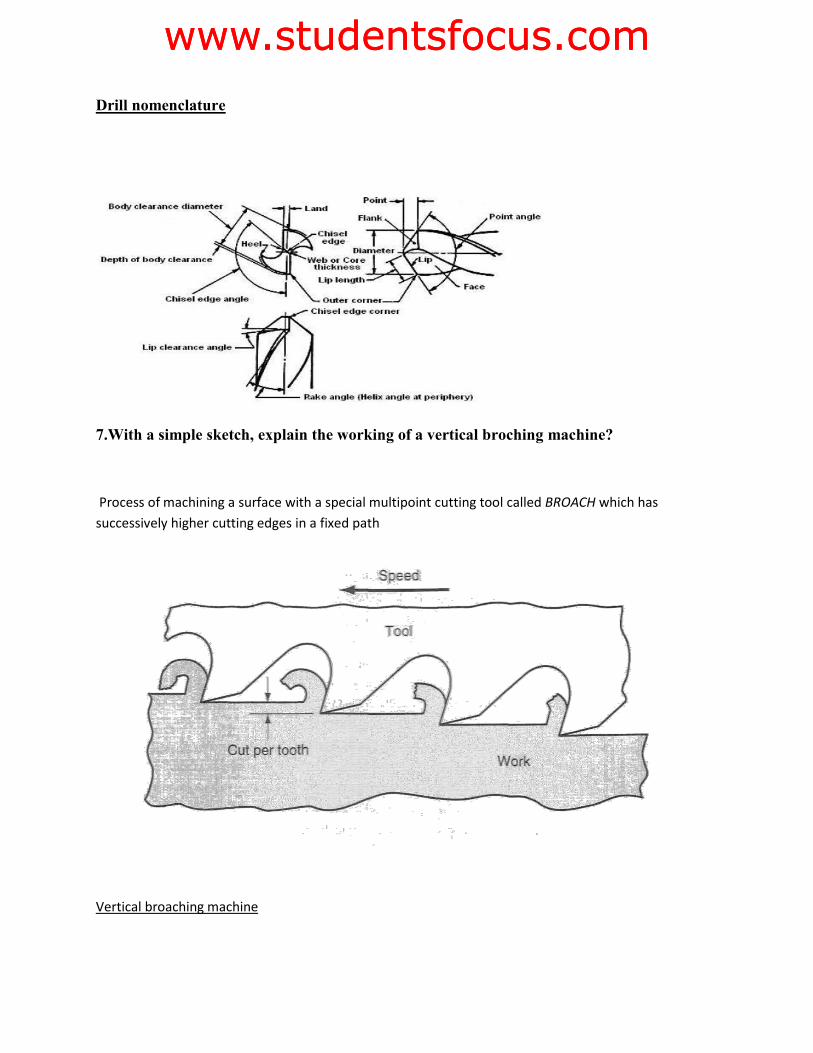
Drill nomenclature
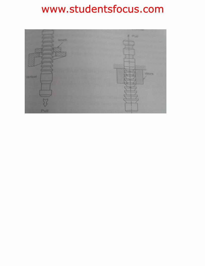
7.With a simple sketch, explain the working of a vertical broching machine?
Process of machining a surface with a special multipoint cutting tool called BROACH which has successively higher cutting edges in a fixed path
Vertical broaching machine
www.studentsfocus.comwww.studentsfocus.com
www.studentsfocus.comwww.studentsfocus.com


![EN Gear Milling Presentation.ppt [Kompatibilitätsmodus] · GEAR MILLING SPECIALS ... - quality AA acc. DIN 3968. Thank you very much for your attention. Title: Microsoft PowerPoint](https://static.fdocuments.us/doc/165x107/5b4374ab7f8b9abe2a8b56eb/en-gear-milling-kompatibilitaetsmodus-gear-milling-specials-quality.jpg)