Shape variable seals for pressure actuated cellular structures
13
Shape variable seals for pressure actuated cellular structures B. Gramüller, A. Tempel, C. Hühne German Aerospace Center, Institute of Composite Structures and Adaptive Systems E-Mail: [email protected] Abstract Sealing concepts allowing a large change of cross-sectional area are investigated. Shape variable seals are indispensable for the biologically inspired pressure actuated cellular structures (PACS), which can be utilized to develop energy efficient, lightweight and adaptive structures for diverse applications. The requirements regarding extensibility, stiffness and load capacity exceed the characteristics of state of the art solutions. This work focuses on the design of seals suitable for extensional deformations greater than 25 %. In a first step, a number of concepts are generated. Then the most suitable concept is chosen based on numerical characterization and experimental examination. The deformation supportive end cap (DSEC) yields satisfying results as it displays a stress optimized shape under maximum load, an energetically inexpensive bending-based deformation mechanism and utilizes the applied forces to support distortion. In the first real-life implementation of a double row PACS demonstrator, which contains DSEC, the proof of concept is demonstrated. 1 Introduction Shape variable structures present great potential regarding design, flexibility and functionality for a wide range of applications. The integration of morphing capabilities allows for the development of novel structures and tools, which hold the potentials to save weight, increase efficiency and reduce complexity. The demands on such concepts can be summarized by two basic challenges. First, adaptive structures have to be profitable. A shape variable high lift system for airplanes may improve the aerodynamic efficiency during take- off and landing, but could be uneconomical because of increased weight, complexity and cost of the overall system. Although the advantages of adaptive structures in immobile, automotive or aeronautical applications differ, they have to outweigh the efforts and risks of implementing these morphing concepts. Second, a convenient shape changing structure circumvents the dilemma of geometric flexibility, mechanical stiffness and strength. Pressure actuated cellular structures (PACS) provide lightweight, energy efficient solutions for a wide range of applications with their specific challenges. In this work, shape variable seals are investigated for a sample PACS structure, though the implemented concepts can be adapted for other arbitrary structures with deformable sealing area. After clarifying the basic requirement of shape variable cell closures, different concepts with individual advantages and disadvantages are presented. The selection of the preferential sealing concept is followed by the description of a suitable assembly concept. The subsequent evaluation includes the material selection, investigates the impact of design parameters, and provides the proof of concept using two tested structures. 1.1 Use case - PACS Pressure actuated structures possess a number of essential advantages over other morphing concepts. Performance studies about mechanical actuators by Huber et al. [1] identified fluid powered devices as the most efficient with respect to power density, actuation strain and resolution. Various aeronautical applications exist form the scale of wing tips [2] to full aircraft structures [3]. Vasista et al. [4] use air pressure to actuate their topology optimized morphing trailing edge structure. The direct pressurization of shape variable tube like structures distributes forces and eliminates the strict functional separation of actuator and structure. They conceived and calculated a trailing edge flap, that allows tip deflections of up to 9° at a pressure of 0.1 MPa. Based on pressure adaptive honeycombs (PAH), Vos et al. [5] investigated and patented [6] a similar concept that allows adjusting a flap’s shape. Barrett et al. [7] showed the positive effects of pressure stiffened control surfaces with regard to microbursts. The operating pressure is limited to 0.1 MPa for their application. The variation in the cells’ pressure allows for the biomimetic PACS structure to move between predefined form functions. The flexibility of this concept is based on the individual shape changing ability of the cell elements, which are assembled to yield the actual cell compound. The need for adaptive structures, which can be satisfied by PACS, ranges from aircraft applications like the high-lift device droop nose, gapless flaps, and shape variable airfoils to the automotive sector that would profit from smoothly adjustable seats or rear spoilers. A solar radiation driven PACS structure, which uses vapor pressure, could be used to autonomously align photovoltaic collectors towards the current position of the sun. Theoretical research about PACS and their applications are investigated by Pagitz et al. [8], [9] and Gramüller et al. [10]. The practicability of the concept is verified for the first time by a single row cantilever test body, which demonstrated a tip deflection of 123° at a length of 300 mm and a maximum pressure of 0.2 MPa [11]. Figure 1 depicts the principle behind the PACS structures. It is based on pressure induced forces that lead to the energetically favored state of shape where the enclosed volume is maximized. For a cell pressure change from 0 = 0 to 1 > 0 , the shape of a single cell shifts from the initial state 0 to a deformed state 1 . In the case of a cell compound, a shape variable cantilever, that moves between predefined shape functions, results. The depicted PACS cantilever is designed according to [10] and moves between two circular arc positions. The first real life implementation of a double row PACS structure with a total length of 450 mm is presented in chapter 5.4. Figure 1: Principle of a double row PACS structure All of the introduced pressure actuated structures overcome the second challenge for morphing structures using one characteristic property. Even though the initial body is very
Transcript of Shape variable seals for pressure actuated cellular structures

Shape variable seals for pressure actuated cellular structures B. Gramüller, A. Tempel, C. Hühne
German Aerospace Center, Institute of Composite Structures and Adaptive Systems E-Mail: [email protected]
Abstract Sealing concepts allowing a large change of cross-sectional area are investigated. Shape variable seals are indispensable for the biologically inspired pressure actuated cellular structures (PACS), which can be utilized to develop energy efficient, lightweight and adaptive structures for diverse applications. The requirements regarding extensibility, stiffness and load capacity exceed the characteristics of state of the art solutions. This work focuses on the design of seals suitable for extensional deformations greater than 25 %. In a first step, a number of concepts are generated. Then the most suitable concept is chosen based on numerical characterization and experimental examination. The deformation supportive end cap (DSEC) yields satisfying results as it displays a stress optimized shape under maximum load, an energetically inexpensive bending-based deformation mechanism and utilizes the applied forces to support distortion. In the first real-life implementation of a double row PACS demonstrator, which contains DSEC, the proof of concept is demonstrated.
1 Introduction
Shape variable structures present great potential regarding design, flexibility and functionality for a wide range of applications. The integration of morphing capabilities allows for the development of novel structures and tools, which hold the potentials to save weight, increase efficiency and reduce complexity. The demands on such concepts can be summarized by two basic challenges. First, adaptive structures have to be profitable. A shape variable high lift system for airplanes may improve the aerodynamic efficiency during take-off and landing, but could be uneconomical because of increased weight, complexity and cost of the overall system. Although the advantages of adaptive structures in immobile, automotive or aeronautical applications differ, they have to outweigh the efforts and risks of implementing these morphing concepts. Second, a convenient shape changing structure circumvents the dilemma of geometric flexibility, mechanical stiffness and strength. Pressure actuated cellular structures (PACS) provide lightweight, energy efficient solutions for a wide range of applications with their specific challenges. In this work, shape variable seals are investigated for a sample PACS structure, though the implemented concepts can be adapted for other arbitrary structures with deformable sealing area. After clarifying the basic requirement of shape variable cell closures, different concepts with individual advantages and disadvantages are presented. The selection of the preferential sealing concept is followed by the description of a suitable assembly concept. The subsequent evaluation includes the material selection, investigates the impact of design parameters, and provides the proof of concept using two tested structures.
1.1 Use case - PACS
Pressure actuated structures possess a number of essential advantages over other morphing concepts. Performance studies about mechanical actuators by Huber et al. [1] identified fluid powered devices as the most efficient with respect to power density, actuation strain and resolution. Various aeronautical applications exist form the scale of wing tips [2] to full aircraft structures [3]. Vasista et al. [4] use air pressure to actuate their topology optimized morphing trailing edge structure. The direct pressurization of shape variable tube like structures distributes forces and eliminates the strict functional separation of actuator and structure. They conceived and calculated a trailing edge flap, that allows tip deflections of up to 9° at a pressure of 0.1 MPa. Based on pressure adaptive honeycombs (PAH), Vos et al. [5] investigated and patented [6] a similar concept that allows adjusting a flap’s shape. Barrett et al. [7] showed the positive effects of pressure stiffened control
surfaces with regard to microbursts. The operating pressure is limited to 0.1 MPa for their application. The variation in the cells’ pressure allows for the biomimetic PACS structure to move between predefined form functions. The flexibility of this concept is based on the individual shape changing ability of the cell elements, which are assembled to yield the actual cell compound. The need for adaptive structures, which can be satisfied by PACS, ranges from aircraft applications like the high-lift device droop nose, gapless flaps, and shape variable airfoils to the automotive sector that would profit from smoothly adjustable seats or rear spoilers. A solar radiation driven PACS structure, which uses vapor pressure, could be used to autonomously align photovoltaic collectors towards the current position of the sun. Theoretical research about PACS and their applications are investigated by Pagitz et al. [8], [9] and Gramüller et al. [10]. The practicability of the concept is verified for the first time by a single row cantilever test body, which demonstrated a tip deflection of 123° at a length of 300 mm and a maximum pressure of 0.2 MPa [11]. Figure 1 depicts the principle behind the PACS structures. It is based on pressure induced forces that lead to the energetically favored state of shape where the enclosed volume is
maximized. For a cell pressure change from 𝑝𝑠𝑡0 = 0 𝑀𝑃𝑎 to
𝑝𝑠𝑡1 > 0 𝑀𝑃𝑎, the shape of a single cell shifts from the initial
state 𝑠𝑡0 to a deformed state 𝑠𝑡1. In the case of a cell
compound, a shape variable cantilever, that moves between predefined shape functions, results. The depicted PACS cantilever is designed according to [10] and moves between two circular arc positions. The first real life implementation of a double row PACS structure with a total length of 450 mm is presented in chapter 5.4.
Figure 1: Principle of a double row PACS structure
All of the introduced pressure actuated structures overcome the second challenge for morphing structures using one characteristic property. Even though the initial body is very

flexible, the structural stiffens as it is pressurized. The higher the inherent pressure, the higher the structure’s rigidity. Thus there is an essential demand for shape variable seals, which only allow the realization of pressure actuated morphing concepts and significantly influence their performance.
1.2 Demands on seals for PACS
The main challenge in developing a suitable end cover for shape variable cross sections is to combine the conflicting aims of structural strength so as to withstand out of plane (pressure) and deforming forces, flexibility with respect to the in plane deformations and tolerable installation space. Two dimensional considerations of the PACS concept are described in [8], [9] and [10], where the underlying computational methods are validated by FEM-simulation and first experimental tests. The cell end covers, an elementary part of each three dimensional PACS structure, is first implemented in [11], but not investigated sufficiently. Depending on the depth of the cell tubes, the geometrical portion of the seal significantly influences the global mechanical behavior of PACS. Thus the conception, implementation, and characterization of different sealing solutions are necessary to maximize the performance of PACS. The following work analysis and discusses in detail the requirements of shape variable seals for PACS.
The interface between seal and cell structure can be reduced to the two dimensional cross section of a single PACS cell. Consisting of assumed rigid cell sides and flexible compliant hinges, the base structure’s main deformations are concentrated in areas with low wall thickness. In addition to an irregular distribution of in plane deformations resulting from the cells’ kinematics, this varying wall thickness leads to the narrowing at corner angles. Figure 2 visualizes the requirements on seals for PACS and relates them to pressure allocation, mechanical demands and geometrical boundaries. Pressure allocation capabilities divide the affected zones into cell sides (A1), hinges (A2) and edge regions (A3) near the interface plane. An optimal concept would allow for a constant pressurization of all three zones. The tube cartridge system implemented for pressurizing the single row PACS cantilever [11] showed slight disadvantages regarding (A2). The inherent stiffness of the elastic tube prevents the pressurization of sharp corners. The most basic mechanical requirement for the sealing concept addresses the structural strength (B1). A pressure of 0.5 MPa causes axial forces of about 1 kN for a cell diameter of 50mm, which have to be carried by the sealing system. A high grade of deformability (B2) and infinitesimal counteraction (B3) are in contradiction to strength focused designs and thus a compromise must be found. The design freedom is limited by geometrical boundary conditions. As the cellular compound consists of multiple adjacent cell tubes, the installation space is restricted to half of a wall thickness in the case of (C1). Depending on the applied cell material, the hinge thickness range lies usually between 0.2 mm and 1.0 mm. The need for adaptability to different cell side lengths and cell sizes is based on the concept of PACS (C2). In case of failure or for maintenance work, the system has to be easily accessible (C3). The demands on the sealing concept for PACS are essential for the subsequent concept generation and selection.
Figure 2: Demands on shape variable sealing concepts exemplary shown for PACS structures
2 Sealing Concepts
Different concepts, which fulfill the particular requirements for PACS structure seals with varying efficiency, are investigated. A holistic solution for the covers of the cells’ ends includes a concept for an airtight sealing of the cell tube openings and also for a pressure tight connection between seal and cell structure. As the connection between the cell and the seal depends on the manufacturing and assembly process, and does not imperatively exceed state of the art solutions, this chapter focusses on the investigation of airtight seals. After an overview of conventional sealing solutions from literature, a collection of five relevant concepts is presented. The emphasis of this chapter lays on the implementation of a form finding strategy for isotensoid and deformation supportive seals. An evolutionary conception profits from the existing seal concepts and tries to adapt them to current needs. Hence, available solutions are investigated in order to summarize the state of the art and to provide the ground work for novel concepts (cf. Figure 3). The partitioning of neighboring volumes by separating the contained located fluids of similar or differing pressure is the main function of seals. Static seals are used to connect adjoining partners, which do not move relative to each other. Dynamic seals allow relative motions [12]. Static seals, like gaskets and sealing rings, which can be used for pressure gradients above 100 MPa, are maintenance free and wear resistant. Due to the cross sectional in plane deformation, their application is limited to cell axial implementations. A solution for the mechanical demand on large translational strain to seal off the open cell ends cannot be deduced. The advantages of dynamic seals are the ability to allow translational and rotational displacements as well as the ability to compensate gap variations perpendicular to the plane of the seal. While in contact with the inner cell surface, the touch contacted dynamic seal is not able to close openings, which are multiples of seal’s profile height in size. Attaching the seal in cell axial direction would solve the problem but requires a static sealing partner at both ends of the PACS structure. An implementation using two glass plates containing the structure is not feasible for outside of the laboratory. Special types of seals extend the potential scope of conventional PACS concepts. Compression seals are

conceived to compensate large deformations perpendicular to the contact plane. Sealing high pressures over large areas requires a great thickness to raise the bending stiffness, which coincidently increases the in plane stiffness. Vos et al. [5] used airtight plastic bladders, which are evaluated by experiment for a cell differential pressure of 0.04MPa. In [11] a concept is chosen that consists of a rigid core surrounded by a thin, flexible membrane, which compensates deformations and is tested with a maximum pressure of 0.35MPa. Disadvantages regarding attrition, additional load paths and pressure limitations led to the rejection of these two concepts. Bellows similarly handle huge displacements, but are not suited to bear loads perpendicular to the cross sectional plane of the PACS structure. Inflatable seals are very complex, in need of a separate pressure supply and influence the cell’s deformation behavior. The geometric flexibility and similar functional principle is beneficial.
Figure 3: Conventional seal concepts (from l. to r.): gasket, O-ring, rotary shaft seal, V-ring, compression seal, bellow, inflatable seal
As the demands on shape variable seals for PACS exceed the performance of conventional solutions, the following investigations were necessary to provide suitable concepts.
2.1 Flat plate
The simplest way of sealing the cells’ ends is given by a flat plate. The advantages of this concept are the optimal wetting capabilities, its adaptability to arbitrary cell geometries and the straightforward manufacturing. The deformability can be ensured by considering the required elasticity during the selection of materials. Necessary fracture strains of more than 25 % predestine elastomers for these applications. To limit the out of plane deformations, the minimum plate thickness can be estimated analytically according to the plate theory of Timoshenko [13]. The maximum deflection of a uniformly loaded circular plate is:
(1) 𝑤𝑚𝑎𝑥 =𝑝𝑎4
64𝐷=3𝑝𝑎4(1−𝜈2)
16𝐸𝑡3, with
(2) 𝐷 =𝐸𝑡3
12(1−𝜈2)
The required plate thickness results in
(3) 𝑡𝑚𝑖𝑛,𝑤 = √3𝑝𝑎4(1−𝜈2)
16𝐸𝑤𝑚𝑎𝑥
3.
Radial 𝜎𝑟 and tangential 𝜎𝑡 stresses are maximal at the edge of
the plate and can be calculated using
(4) 𝜎𝑟,𝑚𝑎𝑥 =3𝑝𝑎2
4𝑡2, and
(5) 𝜎𝑡,𝑚𝑎𝑥 =3𝑝𝑎2
4𝑡2𝜈.
For example, a thermoplastic material with a stiffness 𝐸 =
1300 𝑀𝑃𝑎, a Poisson ratio of 𝜈 = 0.5, a strength 𝑅 = 40 𝑀𝑃𝑎, a
pressure of 𝑝 = 0.5 𝑀𝑃𝑎 and an estimated plate radius of
𝑎 = 25 𝑚𝑚 requires a minimum plate thickness of 𝑡𝑚𝑖𝑛,𝜎 =
2.42 𝑚𝑚 for a deflection of 𝑤𝑚𝑎𝑥 = 1.49 𝑚𝑚. The resulting in
plane stiffness is responsible for the huge amount of energy required to deform the seal. An additional mechanical problem occurs in the form of leakage. The higher the forces needed to deform the seal, the higher the loads on the connection
between cell structure and seal. Leakage and overstressing occur at the thin walled flexure hinges as observed in chapter 5.3. In order to increase the ratio between bending and axial stiffness, a sandwich construction can be used. Figure 11 shows the trial structure of an aramid honeycomb sandwich with elastomer skin. Face sheet wrinkling could be avoided by pretensioning the skin material but results in the desired low in plane stiffness. The unevenly distributed appearance of wrinkles indicates stress concentrations and causes delamination.
2.2 Compliant Rib Cap (CRC)
In contrast to the regular honeycomb core, a mechanism, which is adapted to the cells kinematic, allows for evenly distributed deformations. The basic idea is to reduce the in plane stiffness of the seal by facilitating deformations through a shear flexible rib structure. Coincidently the structure can bear out of plane pressure forces due to its bending stiffness. Moreover, the concept presented in this chapter separates the sealing and the force bearing functions due to the main structural elements’ hinged rib structure and thin elastomeric skin. The design principle of the rib structure ensures that each hinge is connected to at least three neighboring hinges. The kinematics of each part of the mechanism is thus fully constrained by the surrounding cell structure, respectively by its independent hinge angles. Figure 4 shows the design principle for the sample geometry of an irregular hexagonal PACS cell. Notice that the halving of cell sides results in a division of the original cross sectional area 𝐴0, such that the largest newly
formed subarea 𝐴1 is 𝐴0/4. As the largest newly formed cross
section equates the initial geometry except for its scale, this relation is valid for all convex polygons. The recurrence of independent hinge angles illustrates the equality.
Figure 4: Design principle of the Compliant Rib Cap for division of initial area by four and sixteen and position of independent hinge
angles 𝜶𝟏, 𝜶𝟐 and 𝜶𝟑
Regarding the equations (3), (4) and (5), the following relationships can be obtained:
(6) 𝑡𝑚𝑖𝑛,𝑤~𝑎4/3,
(7) 𝑡𝑚𝑖𝑛,𝜎~𝑎
Thus the quartering of cell sides allows the reduction of the
thickness of the sealing plate to 𝑡1,𝑚𝑖𝑛,𝜎 = 0.605 𝑚𝑚. The in
plane stiffness is thereby decreased to 25.0 % compared to the flat plate. This strategy of dividing the pressurized area into multiple fragments is applicable to arbitrary convex polygons and can be applied for any resolution. Comparable to the divisibility of a parallelogram, the kinematics of the CRC only consists of the ratio of cell side lengths and the cell side orientations which are already used by the surrounding polygon. A real-life implementation of this mechanism is depicted in Figure 11.

2.3 Isotensoid
Out of plane forces cannot be borne efficiently by a two dimensional structure. Large deformations in the cell’s longitudinal direction and bending induced stress limitations arise. A three dimensional isotensoid end cap avoids bending loads and shows a uniform stress distribution over the whole seal. In the following, the procedure of generating this isotensoid seal geometry is presented before the application of this concept to PACS is implemented and particular properties are identified.
2.3.1 Method of generating the isotensoid geometry
Bletzinger et al. [14] and Wüchner et al. [15] investigated the Updated Reference Strategy (URS) for the form finding of minimal surfaces and prestressed isotensoid membranes. This chapter introduces a comparable approach which is adapted to the current problem. After the description of the implemented approach, it is verified by an analytically solvable sample problem. Based on the method of virtual work, the continuum mechanical approach of Bletzinger et al. is summarized in equation (8). The equilibrium state is reached when the virtual work 𝛿𝑤 vanishes.
(8) 𝛿𝑤𝑈𝑅𝑆 = 𝜆𝑡 ∫ 𝑑𝑒𝑡𝑭(𝜎 ∙ 𝑭−𝑇)
𝑎: 𝛿𝑭𝑑𝑎 −
(1 − 𝜆)𝑡 ∫(𝑭 ∙ 𝑺)
𝐴
: 𝛿𝑭𝑑𝐴 = 0
𝑭 is the deformation gradient, 𝐴 the area in the reference
configuration and 𝑎 the area in the actual configuration. The first
term contains the Cauchy stress 𝜎 which describes the
structural stresses related to the actual geometry. As this term
causes singularities, the approach is extended by the second, stabilizing term. As the 2
nd Piola-Kirchhoff stress 𝑺 refers to the
undeformed reference configuration, it is not affected by shape variations. The convergence characteristics of this method depend on the manual determination of the homotopy factor 𝜆.
The basic idea of URS is transferred to a pragmatic implementation within a common FEM software that overcomes the stabilization problem. As illustrated in Figure 5, the problem of calculating minimal surfaces and pressure loaded uniformly stressed membranes is subsequently extended by a strategy, which allows to control deformations.
The minimal surface of arbitrary reference geometry can be reached by calculating the equilibrium state of a homogenously pretensioned membrane, identified as Internal preloads in
Figure 6. The exemplary geometry of a catenoid with diameter 𝑅0 = 1 and height ℎ = ℎ0 = 1.2 is used to demonstrate the
accuracy and convergence behavior of the form finding process. For the reference configuration a cylinder of the same dimensions is used. The model is implemented in ANSYS with 25 shell elements (shell181) over the height and an initial temperature strain of 휀𝑇 = −0.9. The solver is set to consider
non-linear geometrical deformations. Analogue to the URS the computed deformations are used to modify the affected elements and thus the geometry of the membrane. After each iteration step, the model is transformed into its deformed shape. As the envelop surface of the catenoid can be computed analytically, the quality of the results are evaluated by comparison to it. The first chart of Figure 5 attests good convergence for the numerically calculated shape of the catenoid. A negligible deviation of the catenoid’s radius at ℎ = ℎ0/2 compared to the analytical solution ensues already
after two iterations.
The minimal surface is uniformly stressed for even tangential preloads. It is not suitable for bearing external normal forces
and it is equal to the flat plate for the actual flat envelop contour. An overview of the adaptability of URS for the form finding of pressure loaded isotensoid structures is given in [14] with the example of an inflated bubble. Transferred to the cylindrical geometry, an internal pressure forces the membrane to extend (see Figure 5, Pressure formed membrane). Similarly to the example of the literature, the pressure intensity is controlled to start at a high value, which causes large deformations, and is halved after each iteration step until the target pressure is reached. Two problems occur using this strategy. First, the resulting membrane structure is not uniformly stressed. The stress distribution varies by about 30 % (see Figure 5, 2
nd chart). The reason for this is the missing target
geometry. The pressure forces cause an extension of the membrane and the reference geometry is set to the deformed state after each iteration step. As the difference between undeformed and deformed state only depends on the magnitude of the applied forces, which are always oriented to induce positive strains, the geometry cannot converge to a certain shape. For a non-converging geometry, the desired isotensoid shape changes after each iteration step. The remaining difference between actual and target state results in the remaining stress deviation. Beyond that, the size of the curvature cannot be regulated as it depends on the initial pressure set. As it is responsible for the ensuing stress level, the size of the inflated membrane is crucial for the form finding of sealing caps. In addition to the general demand for stress reduction, the height of the end cap reduces the effective length of a PACS cell, which causes a loss of performance. A not controllable bulge is thus not desired for the present application.
Figure 5: FEM-based form finding for (I) minimal surfaces, (II) uniformly stressed membranes, and (I+II) deformation regulated isotensoid membranes
With the extension regulation, which widens the URS, a solution is found for the task of generating a geometry that displays a uniform stress distribution at a specific target pressure and is controllable in size. The strategy for generating minimal surfaces (I) allows to preload membranes uniformly, whereas the pressure formed model (II) includes external forces. The combination of the two approaches leads to an extension regulated URS (ER-URS). The basic idea of this ER-URS is to modify the shape of the elements according to their strains and thus to form the structure according to the load paths of the

external forces. A flow chart, given in Figure 6, visualizes the principle procedure. An initial cylindrical geometry with radius 𝑅0 shall be used as
reference to calculate an isotensoid structure with target radius 𝑅𝑡 at a given pressure load (see Figure 6). The target radius is
extracted as the distance between cylinder axis and membrane element node at ℎ = ℎ0/2. In the initial configuration, stresses
due to external loads are calculated. The stress related strains are superimposed with a uniform internal strain, which is adjusted to the residual geometrical extension ∆𝑅 = 𝑅0 − 𝑅𝑡. The extension of the membrane structure is regulated by shape modifications due to these strains. Figure 6 shows how the shape of a single element is altered during the ER-URS procedure. The iteration step is repeated until the variance compared to the target shape is less than 𝜂𝑅 and the deviation
of stresses falls below 𝜂𝜎.
An example is computed with the same initial geometry as used
for the minimal surface with a pressure load of 𝑝 = 0.5 𝑀𝑃𝑎,
and the target radius 𝑅𝑡 = 1.5𝑅0 (see Figure 5, I+II). For the
first four steps, a high pressure load 𝑝 = 𝑝𝑖𝑛𝑖𝑡 stabilizes large
deformations and accelerates the form finding process until the geometric deviation is less than 𝜂𝑅 =0.1 %. Subsequently the
external force is reduced to its real value 𝑝 = 𝑝𝑡𝑟𝑢𝑒. The second
chart of Figure 5 shows a deviation of stresses of less than 1 % after fourteen iteration steps. A final geometrical variance of 8.7e-8 compared to the target radius was extracted.
Figure 6: Shape modification process of the extension regulated Updated Reference Strategy
A gradient method is used to regulate the cell height. The control element with access to the internal strain is governed by the following equation:
(9) 휀𝑛+1 = 휀𝑛 − (𝑅𝑛 + 𝑑𝑅𝑛 − 𝑅𝑡)( 𝑛− 𝑛−1)
𝑑𝑅𝑛−𝑑𝑅𝑛−1, with
(10) 𝑑𝑅𝑛 = 𝑅𝑛 − 𝑅𝑛−1
2.3.2 Application to PACS
An isotensoid cell closing geometry with a cylindrical base contour can also be calculated analytically as [16] shows for linear elastic isotropic materials. These approaches are not suitable for the issue of sealing a PACS cell with its complex edge contour. The ER-URS strategy is adapted to the sealing of a PACS cell by simply changing the contour of the initial configuration and the corresponding boundary conditions in the numerical model. Figure 7 depicts the isotensoid sealing cap (l.) and the related stress distribution (r.). The production of a complete PACS structure is depicted in chapter 5.4 to clarify the geometrical design. For the model with an element size of 1mm, convergence is reached after ten iteration steps. The geometrical deviation of 4.72e-8 % related to the target cap
height of ℎ = 25 𝑚𝑚 and a residual stress divergence of 0.60 %
are suitable values within the context of PACS.
Figure 7: Isotensoid sealing cap and stress distribution
As for the analytically calculated stresses in the flat plate, the determination of the cell’s diameter allows for an estimate of the stresses in the isotensoid according to the pipe formula:
(11) 𝜎𝑟 = 𝜎𝑡 =𝑝𝑎
2𝑡.
For the sample setup described in chapter 2.1, a reduction of
stress based membrane thickness to 𝑡𝑚𝑖𝑛,𝜎 = 0.16 𝑚𝑚,
meaning 6.6 % compared to the flat plate concept, results.
Based on the example of the complex edge contour of the pentagonal PACS cell’s cross section, it can be assumed that the ER-URS is stable for arbitrary initial configurations. The functional principle is adaptable to other form finding problems. As the shape modification is driven by structural strains, other external forces beyond pressure loads are conceivable. As it could be interesting for components built of fiber reinforced polymers [17], a follow up work should address anisotropic materials.
2.4 Isotensoid Rib Cap (IRC)
Reinforcing the isotensoid membrane with a flexible load bearing rib structure provides the possibility to reduce stresses and thus the membrane thickness and stiffness. As for the CRC, the IRC benefits from a reduced diameter of the segmented sealing surfaces. Dividing the cell sides by four also reduces the sealing stresses or the necessary membrane thickness by four. The minimum thickness of the IRC results in
𝑡𝑚𝑖𝑛,𝜎 = 0.04 𝑚𝑚. A prototype of this concept is produced and
shown in Figure 11. On the left side of the third row, an IRC is depicted with a division of the effective cell side length by two. The illustration on the right hand shows the possibility of a compliant implementation to reduce manufacturing efforts. A division of cell side length by six is established with this demonstrator.
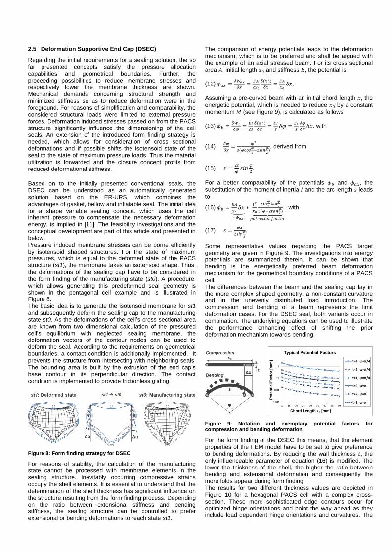
2.5 Deformation Supportive End Cap (DSEC)
Regarding the initial requirements for a sealing solution, the so far presented concepts satisfy the pressure allocation capabilities and geometrical boundaries. Further, the proceeding possibilities to reduce membrane stresses and respectively lower the membrane thickness are shown. Mechanical demands concerning structural strength and minimized stiffness so as to reduce deformation were in the foreground. For reasons of simplification and comparability, the considered structural loads were limited to external pressure forces. Deformation induced stresses passed on from the PACS structure significantly influence the dimensioning of the cell seals. An extension of the introduced form finding strategy is needed, which allows for consideration of cross sectional deformations and if possible shifts the isotensoid state of the seal to the state of maximum pressure loads. Thus the material utilization is forwarded and the closure concept profits from reduced deformational stiffness.
Based on to the initially presented conventional seals, the DSEC can be understood as an automatically generated solution based on the ER-URS, which combines the advantages of gasket, bellow and inflatable seal. The initial idea for a shape variable sealing concept, which uses the cell inherent pressure to compensate the necessary deformation energy, is implied in [11]. The feasibility investigations and the conceptual development are part of this article and presented in below. Pressure induced membrane stresses can be borne efficiently by isotensoid shaped structures. For the state of maximum pressures, which is equal to the deformed state of the PACS structure (st1), the membrane takes an isotensoid shape. Thus, the deformations of the sealing cap have to be considered in the form finding of the manufacturing state (st0). A procedure, which allows generating this predeformed seal geometry is shown in the pentagonal cell example and is illustrated in Figure 8. The basic idea is to generate the isotensoid membrane for st1 and subsequently deform the sealing cap to the manufacturing state st0. As the deformations of the cell’s cross sectional area are known from two dimensional calculation of the pressured cell’s equilibrium with neglected sealing membrane, the deformation vectors of the contour nodes can be used to deform the seal. According to the requirements on geometrical boundaries, a contact condition is additionally implemented. It prevents the structure from intersecting with neighboring seals. The bounding area is built by the extrusion of the end cap’s base contour in its perpendicular direction. The contact condition is implemented to provide frictionless gliding.
Figure 8: Form finding strategy for DSEC
For reasons of stability, the calculation of the manufacturing state cannot be processed with membrane elements in the sealing structure. Inevitably occurring compressive strains occupy the shell elements. It is essential to understand that the determination of the shell thickness has significant influence on the structure resulting from the form finding process. Depending on the ratio between extensional stiffness and bending stiffness, the sealing structure can be controlled to prefer extensional or bending deformations to reach state st1.
The comparison of energy potentials leads to the deformation mechanism, which is to be preferred and shall be argued with the example of an axial stressed beam. For its cross sectional area 𝐴, initial length 𝑥0 and stiffness 𝐸, the potential is
(12) 𝜙𝑎𝑥 =𝛿𝑊𝑎𝑥
𝛿𝑥=
𝐸𝐴
2𝑥0
𝛿(𝑥2)
𝛿𝑥=𝐸𝐴
𝑥0𝛿𝑥.
Assuming a pre-curved beam with an initial chord length 𝑥, the
energetic potential, which is needed to reduce 𝑥0 by a constant
momentum 𝑀 (see Figure 9), is calculated as follows
(13) 𝜙𝑏 =𝛿𝑊𝑏
𝛿𝜑=𝐸𝐼
2𝑠
𝛿(𝜑2)
𝛿𝜑=𝐸𝐼
𝑠𝛿𝜑 =
𝐸𝐼
𝑠
𝛿𝜑
𝛿𝑥𝛿𝑥, with
(14) 𝛿𝜑
𝛿𝑥=
𝜑2
𝑠(𝜑𝑐𝑜𝑠𝜑
2−2𝑠𝑖𝑛
𝜑
2), derived from
(15) 𝑥 =2𝑠
𝜑𝑠𝑖𝑛
𝜑
2.
For a better comparability of the potentials 𝜙𝑏 and 𝜙𝑎𝑥, the
substitution of the moment of inertia 𝐼 and the arc length 𝑠 leads
to
(16) 𝜙𝑏 =𝐸𝐴
𝑥0𝛿𝑥
⏟ =𝜙𝑎𝑥
∗𝑡2
𝑥0
𝑠𝑖𝑛𝜑
2tan
𝜑
2
3(𝜑−2𝑡𝑎𝑛𝜑
2)⏟
𝑝𝑜𝑡𝑒𝑛𝑡𝑖𝑎𝑙 𝑓𝑎𝑐𝑡𝑜𝑟
, with
(17) 𝑠 =𝜑𝑥
2𝑠𝑖𝑛𝜑
2
.
Some representative values regarding the PACS target geometry are given in Figure 9. The investigations into energy potentials are summarized therein. It can be shown that bending is the energetically preferred beam deformation mechanism for the geometrical boundary conditions of a PACS cell. The differences between the beam and the sealing cap lay in the more complex shaped geometry, a non-constant curvature and in the unevenly distributed load introduction. The compression and bending of a beam represents the limit deformation cases. For the DSEC seal, both variants occur in combination. The underlying equations can be used to illustrate the performance enhancing effect of shifting the prior deformation mechanism towards bending.
Figure 9: Notation and exemplary potential factors for compression and bending deformation
For the form finding of the DSEC this means, that the element properties of the FEM model have to be set to give preference to bending deformations. By reducing the wall thickness 𝑡, the only influenceable parameter of equation (16) is modified. The lower the thickness of the shell, the higher the ratio between bending and extensional deformation and consequently the more folds appear during form finding. The results for two different thickness values are depicted in Figure 10 for a hexagonal PACS cell with a complex cross-section. These more sophisticated edge contours occur for optimized hinge orientations and point the way ahead as they include load dependent hinge orientations and curvatures. The

sealing cap on the right side was formed with half the thickness of the geometry on the left. Notice that the folding of the two sealing cap configurations significantly differs.
Figure 10: Effects of wall thickness on the results of the form finding
The DSEC is an efficient solution for sealing PACS cells. Moreover, it has the advantage of a nearly isotensoid shape in the state of maximum pressure induced deformation and a minimized stiffness against this change of shape. Figure 10 illustrates that this form finding strategy is suitable for geometrically complex basis contours and converges in a stable manner. The influence of varying initial wall thickness on form finding is investigated in chapter 5.2.
3 Concept selection
The presented concepts are rated based on the analysis in chapter 1.2 and a characterization of properties. The subsequent selection of an optimum solution reduces efforts in the following evaluation. Table 1 summarizes the advantages and disadvantages of the different concepts corresponding to Figure 2.
Conventional concepts provide good wetting capability as well as exchangeability. Prior research showed that off the shelf sealing concepts are not capable of compensating strains larger than 25 %. This eliminates the first group of potential solutions. The flat plate for casting a complete PACS segment benefits from good wetting capability and an excellent adaptability to various cell geometries. The particularly high in plane stiffness and difficulties with maintenance and repair are distinct disadvantages (cf. Figure 11 and Figure 13). The CRC improves the load bearing and stiffness characteristics of the seal. Since each cell shape has an individual mechanism, which can hardly be applied to adjacent cells, this concept is also slightly inconvenient. A hinge based prototype structure for this concept is shown in Figure 11. Conceived to optimize the stress distribution within the sealing material, the shape optimized isotensoid seal is well suited for carrying pressure forces (see Figure 13). The pressurization of the edge region is not ensured. As the isotensoid shape constitutes the energetic minimum of a pressured cell closure, the deformation is hindered for increasing pressures. With a higher conceptual complexity and the problem of intersecting hinges of neighboring cells, the IRC is less suitable than the Isotensoid cell closure. Figure 11 shows a hinge based and a compliant prototype of the IRC. Regarding the pressurization of cell sides and hinge regions, the DSEC seal shows as good performance as other concepts.
The cells’ edge region profits from the folded cap shape. The isotensoid shape is calculated for the deformed shape st1 of the cell and builds an energetic minimum with maximum volume. Due to the smoothing of wrinkles, the enclosed volume enlarges during deformation and the seal converges automatically to the target shape for increasing pressures. Since the interface region between cell and seal behaves as the cell structure does, an efficient wetting, and simultaneously low stiffness result. High grades of contour deformation can be realized without a violation of the geometrical boundaries.
Table 1: Characterization of sealing concepts regarding the requirements listed in Figure 2
\Demand Concept A1 A2 A3 B1 B2 B3 C1 C2 C3 SUM
Conv. + + 0 0 - 0 0 - + +1 Flat plate + + + 0 0 - + + - +3 CRC + + + + 0 0 - 0 - +2 Isotensoid + + - + 0 0 + 0 0 +3 IRC + + - + 0 0 - 0 0 +1 DSEC + + + + + + + 0 0 +7
Due to the assessment of concepts, the DSEC seal is selected as the preferred and most efficient sealing concept. Beyond that, the flat plate and the isotensoid seal are considered as reference in the evaluation (see Figure 13).
Figure 11: Realization of sealing concepts flat plate - sandwich stiffened (l.), face sheet wrinkling (r.) - CRC and IRC
4 Assembly of cell and sealing
To give a complete description of capping shape variable cellular structures, Figure 12 illustrates the assembly and sealing concept for the selected DSEC cap. The depicted

solution for connecting cell and seal is developed for differentially manufactured components. An integral production of cell and closure is also conceivable. The pressure port is conceived to be located at one of the rigid cell sides, for the single cell and the PACS cell compound. An internal fluid flow duct reduces interfaces and weight. Redundancy requirements for aeronautical certification may make it necessary to allow for individual pressurization of single cells. For this purpose, low-stressed end cap regions can alternatively be used to realize local fluid introduction.
Figure 12: Assembly concept for DSEC
For the connection between DSEC seal and PACS cell, the cap is extended by a gasket seam. Bolting provides axial forces for the clamping of the DSEC so as to be pressure tight between mounting frame and cell structure, and it transfers pressure induced forces from the sealing to the robust cell sides. The minimum overall axial bolt force 𝐹𝑎𝑥 is calculated according to
[12]:
(18) 𝐹𝑎𝑥 = 𝑚𝑎𝑥 (𝐹𝐷𝑉 + 𝐹𝑆𝐵), with
(19) 𝐹𝐷𝑉 = 𝜋𝑑𝐷𝑘0𝐾𝐷 and
(20) 𝐹𝑆𝐵 = 𝜋𝑝(1
4𝑑𝐷2 + 𝑑𝐷𝑆𝐷𝑘1)
To compute the preforming force 𝐹𝐷𝑉 of the gasket, the average
seal diameter 𝑑𝐷 and the tabular information of the effective
width 𝑘0 and deformation resistance 𝐾𝐷 are needed (cf. [12]).
The additional input of the pressure load 𝑝, the safety factor 𝑆𝐷
and the fictive effective width 𝑘1 lead to the minimum bolt force
𝐹𝑆𝐵.
The shape of the DSEC and the assembly concept are covered by patent application number 10 2015 102 189.7 (not published yet).
5 Investigation of DSEC for application in PACS
The functionality of the shape variable seal concept is validated in four steps. As input for the subsequent FEM simulation, the materials and the corresponding manufacturing process are described. The numerical simulation of the DSEC allows characterizing the preferred solution using parameters like wall thickness and material stiffness. The gained insights are transferred to an experimental test setup involving a single cell so as to validate the computational results. A double row PACS structure shows the practicability in an actual application.
5.1 Materials and manufacturing
The manufacturing process strongly depends on the type of material. The numerical investigations of potential sealing materials with different elastic moduli showed that elastomers provide suitable results for this application (cf. chapter 5.2). For
an average cell radius of 𝑎 = 25 𝑚𝑚 and a sealing wall
thickness of 𝑡 = 1…3 𝑚𝑚, a geometrical tolerance of ∆𝑡 =
0.1 𝑚𝑚 is acceptable considering assembly and structural
strength. Here is a preselection of production techniques:
Compression molding
Vacuum casting
Injection molding
Blow molding
Dip molding
Selective Laser Sintering (SLS)
In order to reach the fullest potential of the concept, a PACS structure is designed consisting of multiple individually shaped cells with varying base contours. Hence, a distinct mold for each seal cap is needed for the first five manufacturing techniques. Additionally, undercuts impede the mold construction. A novel elastomer material, the thermoplastic polyurethane TPU-92A, used for the SLS process provides
satisfying material characteristics. These are described below and lead to a fast and economic production of prototypes (see Figure 13).
Figure 13: Produced sealing concepts flat plate, Isotensoid and DSEC manufactured in SLS process with TPU92-A
For the FEM based evaluation of the DSEC concept, the hyperplastic material properties of TPU-92A are thus examined. Figure 14 shows a summarizing chart of the optical strain measurements, which are gained according to the DIN EN ISO 527-2 test norm. As illustrated, the optical system (GOM Aramis) analyses a monochrome dot pattern on the sample so as to compute longitudinal and lateral strains, 휀𝑦 and 휀𝑥. E
modulus and Poisson’s ratio can thus be derived.
Figure 14: Results from the optical measurement of longitudinal and lateral strain at a horizontally sintered TPU-92A specimen
The optical measurement is stable for strains below 100 %. Flaking patterns, which occur at higher deformations, prevent

from measuring values above 100% strain with the optical system. The ultimate elongation of the material though lies between 200 % and 400 %. The data from the optical system is used in two ways. First, it enabled the calculation of the Poisson’s ratio. Second, as Figure 15 shows, it was used for a fitting of optically and mechanically measured test data.
As the orientation of the component in the machine bed affects the material characteristics, an anisotropic mechanical behavior results. Two sets of specimens which are manufactured in horizontal (xy-axis) and perpendicular (z-axis) machine bed orientation are thus used. Figure 15 condenses the outcomes for both material orientations and mechanically and optically measured data. The linearization of the stress-strain curves leads to the resulting input data for FEM computations. The initial gradient for finding the yield point of the highly nonlinear
material stiffness is evaluated between 휀𝑦1 = 0 % and 휀𝑦2 =
10 %. As the linearized data for the specimens of the two
orientations differ by about 25 % of stress, the final values used in the FEM model are mean values of the two linearized functions.
Figure 15: Stress-strain plot for different manufacturing directions and according derived FEM data
An initial E modulus of 𝐸 = 29.08 𝑀𝑃𝑎 results and a Poisson’s
ratio of 𝜈 = 0.38 is derived. The non-linear stiffness properties of TPU-92A for the following FEM simulation are posted in
Table 2. Physical implementations of sealing caps made from this material are investigated in chapter 5.3.
Table 2: Stress-strain linearization for FEM-input
Step 0 Step 1 Step 2 Step 3 Step 4
Strain [%] 0 16.37 100 175 380 Stress [MPa] 0 4.76 6.80 9.11 19.25
5.2 Design sensitivities
The efficiency of a DSEC seal depends on three major design parameters. As it is shown analytically in chapter 2.5, the most efficient shape of a DSEC seal is found by prioritizing the bending over the extensional deformation mode. The effects of varying thicknesses during the form finding process are investigated numerically. Due to the ability of setting arbitrary end cap heights in the form finding strategy, an optimization allows to determine the cap dimensions yielding the overall best solution with respect to energy. The basic idea is to find the optimum ratio between sealing length and remaining cell length, which provides the deformational energy, without increasing the overall dimensions of the PACS structure. Beyond that, the influence of the applied material properties and wall thicknesses
is examined before the acquired information is used to compare the DSEC solution with an isotensoid shaped seal and a flat plate. A comparison of pressure dependent cell and seal behavior shall clarify the similarity of their functional principle.
The selected sample pentagonal cell geometry is similar to those used in the double row cantilever, which is presented in chapter 5.4. With a target deformation of ∆𝛼 = 8.5° (cf. Figure 8)
and the assumed diameter of 𝑑𝐷 = 50 𝑚𝑚, the sealing contour
is representative for the application in a double row PACS structure, like shown in chapter 5.4. A sensitivity analysis is processed to find a suitable discretization of the DSEC geometry for the subsequent investigations. For the seal height
of 𝑧𝑚𝑎𝑥 = 25 𝑚𝑚, the sensitivity curve and the respective
computation time compared to the most expensive variant are illustrated in Figure 16. With a deviation from the isotensoid stress distribution of less than 1 % and a tolerable computational expense, an element size of 1 mm is chosen for the subsequent examinations.
Figure 16: Sensitivity analysis and computational expense for isotensoid geometry
The minimum applicable shell thickness for form finding, which results in a stable computation process, is 𝑡𝐹𝐹,𝑚𝑖𝑛 = 0.01(𝑑𝐷/2).
For thinner sealing structures, the nonlinear solver does not converge for the described modeling. The reason for this limitation lies in the snap through of folds. It was observed, that for increasing deformation and thicknesses below 𝑡𝐹𝐹,𝑚𝑖𝑛,
compression loaded areas of the cap abruptly change their wrinkling pattern. Analogues to equation (16), it is found that the E modulus of isotropic materials does not affect the DSEC seal’s shape. For the comparison of different design parameters, the energy potential provides a key value. It is extracted from the FEM simulation in the form of the totalized cell side momentum 𝑀𝑡𝑜𝑡 that is needed to deform the PACS cell by an angle ∆𝛼 (cf.
Figure 16). As the efficiency of the sealing is evaluated according to its pressure dependent behavior in the plane of the cell’s cross section, the respective in plane momentum provides the necessary information. The similarity of the behavior of DSEC seal and PACS cell, which is designed to use the applied internal pressure, is evaluated in Figure 17 for two pressure values. Three different seal shapes generated using the shell thicknesses 𝑡𝐹𝐹 = 𝑡𝐹𝐹,𝑚𝑖𝑛, 𝑡𝐹𝐹 = 5𝑡𝐹𝐹,𝑚𝑖𝑛 and 𝑡𝐹𝐹 = 10𝑡𝐹𝐹,𝑚𝑖𝑛
(from l. to r.) are shown together with their deformation dependent behavior. On the left side, the total momentum on the cell sides from the sealing cap is depicted. The right graph shows the differential momentum between seal and undisturbed cell structure, which allows evaluating the efficiency of the seal compared to the individual PACS cell. The positive momentum 𝑀𝑡𝑜𝑡 causes a positive deformation ∆𝛼. The differential
momentum 𝑀𝑑𝑖𝑓 is oriented in the same way and compares the
potentials of cell and seal.

In accordance with chapter 2.5, the flexible design with vigorous folding, which results from the minimum shell thickness setting, yields the highest potential for deformation and the least difference compared to the deformation of the unsealed cell structure.
Figure 17: Effects of shell thickness induced DSEC seal shapes on seal momentum
The height of the sealing cap is the second significant parameter of the DSEC concept. The effect on the overall energy efficiency is again investigated to enhance the cap geometry. Therefore three DSEC seals are generated with the
cell heights of 𝑧1,𝑚𝑎𝑥 = 20 𝑚𝑚, 𝑧2,𝑚𝑎𝑥 = 25 𝑚𝑚 and 𝑧3,𝑚𝑎𝑥 =
30 𝑚𝑚 (from l. to r.) and a shell thickness of 𝑡𝐹𝐹 = 𝑡𝐹𝐹,𝑚𝑖𝑛.
Figure 18 shows that the largest seal shape provides the highest momentums. As the length of the cell tube has to be reduced by the same amount as the cap is extended, the differential momentum in the right graph reveals the true optimum solution. The DSEC cap with the height ℎ = 𝑑𝐷/2 shows the best performance. It leads to the highest pressure induced deformation and shows the slightest deviations compared to the momentums of the cell near the convergence angle.
Figure 18: Effects of DSEC seal height on seal momentum
With the three dimensional geometrical data from the form finding procedure, one major input for the manufacturing of a DSEC seal is determined. The optimum shape is found for 𝑡𝐹𝐹 = 𝑡𝐹𝐹,𝑚𝑖𝑛 and ℎ = 𝑑𝐷/2 and used for further investigations.
The third parameter, which is included in the sizing, is the seal material and the derived wall thickness. For the simulation,
which is summarized in Figure 20, the stiffness and related shell thickness for the investigated materials are listed in Table 3. Notice that the shell thickness of the seal 𝑡𝑠𝑒𝑎𝑙 is calculated for
the yield stress 𝑅, the maximum pressure 𝑝 = 0.5 𝑀𝑃𝑎 and a
cell diameter of 𝑑𝐷 = 50 𝑚𝑚 using
(21) 𝑡𝑠𝑒𝑎𝑙 =𝑝𝑑𝐷
4𝑅.
Table 3: Material characteristics and property settings
Nr. Material E-modulus
𝐸 [MPa]
Yield stress
𝑅 [MPa]
Thickness
𝑡𝑠𝑒𝑎𝑙 [mm]
1 TPU-92A 29.08 4.76 1.313
2 Arnitel PL420-H 100 5.3 1.179
3 Arnitel PB582-H 300 16.5 0.379
A thin membrane like seal represents the most efficient implementation. The difference between pressure dependent behavior of cell and seal for Arnitel PB582-H is minimal. The selection of materials in Table 3 is limited to elastomers with low stiffness and strength. For materials leading to thinner shell thickness through higher yield strain, an increased deformational performance may be found. Dynamic deformations result for thin structures, similar to the limitation of the shell thickness in the form finding process. An experimental test with a DSEC cap made of the material PA2200 and a thickness of 𝑡 = 0.5 𝑚𝑚 confirmed the computations (see
Figure 19). As this unsteady deformation mechanism yields high dynamic stresses, no further investigations are done in this area. Design enhancement potentials however are conceivable.
Figure 19: Two stable states of shape for DSEC sealing made of
the material PA2200 with a thickness of t=0.5 mm
Figure 20: Effects of applied material and resulting wall thickness on seal momentum
A comparison of the DSEC seal with previously established solutions, i.e. the isotensoid and the flat plate, will evaluate the improvements of the selected concept. Figure 21 visualizes the efficiency advance of the DSEC. Notice that the momentums for the flat plate are plotted at the secondary y-axis. The energy needed to deform the pressurized isotensoid seal is more than twice as high as for the DSEC. The momentums from the flat plate are one order of magnitude higher.
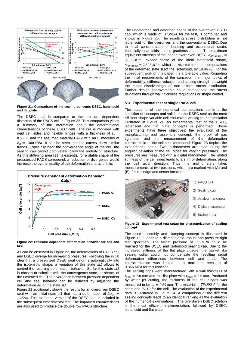
Figure 21: Comparison of the sealing concepts DSEC, isotensoid and flat plate
The DSEC seal is compared to the pressure dependent distortion of the PACS cell in Figure 22. This comparison yields a summary of the information about the deformational characteristics of these DSEC cells. The cell is modeled with rigid cell sides and flexible hinges with a thickness of 𝑡𝐻 =
0.5 𝑚𝑚 and the assumed material PA12 with an E modulus of
𝐸𝐻 = 1300 𝑀𝑃𝑎. It can be seen that the curves show similar
trends. Especially near the convergence angle of the cell, the sealing cap cannot completely follow the underlying structure. As this stiffening area [11] is essential for a stable shape of the pressurized PACS compound, a reduction of divergence would increase the overall quality of the deformation characteristic.
Figure 22: Pressure dependent deformation behavior for cell and seal
As can be observed in Figure 22, the deformations of PACS cell and DSEC diverge for increasing pressures. Following the initial idea that a pressurized DSEC seal deforms automatically into the isotensoid shape, a variation of this state st1 allows to control the resulting deformation behavior. So far this state st1
is chosen to coincide with the convergence state, or shape, of the unsealed cell. The divergence between pressure dependent cell and seal behavior can be reduced by adjusting the deformation ∆𝛼 of the state st1.
Figure 22 additionally shows the results for an overdriven DSEC seal with an initial state st1 that has a deformation of ∆𝛼𝑂𝑉 =1.25∆𝛼. This extended version of the DSEC seal is included in
the subsequent experimental test. The improved characteristics are also used to produce the double row PACS structure.
The undeformed and deformed shape of the overdriven DSEC cap, which is made of TPU92-A for the test, is computed and shown in Figure 25. The resulting stress distribution is not isotensoid for the overdriven and the conventional DSEC. Due to local concentration of bending and extensional strain, especially near folds, stress gradients appear. The maximum equivalent stresses of the loaded overdriven DSEC, 𝜎𝐷𝑆𝐸𝐶,𝑚𝑎𝑥 =
3.366 𝑀𝑃𝑎, exceed those of the ideal isotensoid shape,
𝜎𝐼𝑠𝑜𝑡,𝑚𝑎𝑥 = 2.806 𝑀𝑃𝑎, which is extracted from the computations
of the deformed state st1of the isotensoid, by 19.96 %. For the subsequent work of this paper it is a tolerable value. Regarding the initial requirements of the concepts, the major topics of deformability, stiffness reduction and sealing strength outweight the minor disadvantage of non-uniform stress distribution. Further design improvements could compensate the stress deviations through wall thickness regulations or shape control.
5.3 Experimental test at single PACS cell
The outcome of the numerical computations confirms the selection of concepts and validates the DSEC seal as the most efficient shape variable cell end cover. Analog to the simulation illustrated in Figure 21, an experimental test of the DSEC, isotensoid and flat plate concepts is performed. These experiments have three objectives: the evaluation of the manufacturing and assembly concept, the proof of gas tightness and the measurement of the deformation characteristic of the cell-seal compound. Figure 23 depicts the experimental setup. Two inclinometers are used to log the angular deviation of the cell sides for varying pressures. The pressures are measured with a digital manometer. The limited stiffness of the cell sides leads to a shift of deformations along the cell axial direction. Thus the inclinometers takes measurements at two positions, which are marked with (A) and (B), for cell edge and center location.
Figure 23: Experimental test setup for characterization of sealing concept
The used assembly and clamping concept is illustrated in Figure 12. It leads to a dismountable, robust and pressure-tight test specimen. The target pressure of 0.5 MPa could be reached for the DSEC and isotensoid sealing cap. Due to the increased stiffness of the flat plate closure, the gasket like sealing collar could not compensate the resulting radial deformation differences between cell and seal. The characterization was limited to a maximum pressure of 0.366 MPa for this concept. The sealing caps were manufactured with a wall thickness of
𝑡𝑠𝑒𝑎𝑙 = 2.0 𝑚𝑚 and the flat plate with 𝑡𝑠𝑒𝑎𝑙 = 5.0 𝑚𝑚. Produced by water jet cutting, the thickness of the cell hinges was
measured to be 𝑡𝐻 = 0.69 𝑚𝑚. The material is TPU92-A for the seals and PA12 for the cell. The evaluation of the experimental data is illustrated in Figure 24. A comparison of the different sealing concepts leads to an identical ranking as the evaluation of the numerical examinations. The overdriven DSEC solution is the most efficient implementation, followed by DSEC, isotensoid and flat plate.

Figure 24: Experimental test results at two different measurement positions
The deformation of the overdriven DSEC seal is shown in Figure 26 and illustrates the transition of its shape from the
undeformed, folded state st0 at 𝑝0 = 0 𝑀𝑃𝑎 to the deformed
state st1 at 𝑝1 = 0.5 𝑀𝑃𝑎.
Figure 25: Undeformed and deformed shape of the overdriven DSEC under p = 0.5 MPa pressure load and according stress distribution
Figure 26: Undeformed and deformed shape of the overdriven DSEC seal for p = 0 MPa and p = 0.5 MPa
5.4 Implementation in of double row PACS structure
The successful test of the shape variable sealing concept allows for the production of a double row PACS structure prototype having the following dimensions 450 x 300 x 85 mm³ (length x width x height). It is depicted in Figure 27. After the first production of a single row PACS structure presented in [11], this prototype is an important additional step towards the applicability of PACS to aeronautical structures.
The functionality of a PACS structure was addressed briefly in the introduction and is described in detail in [9]. The conceptual idea is to design each single cell of a PACS compound in a way that the pressurized structure moves between multiple predefined states of shape. As it can be seen in Figure 27, there are two digital manometers measuring the two applied pressures: 𝑝𝑃 for the pentagonal cells, and 𝑝𝐻 being applied to
the hexagonal shaped cells. The maximum pressures are
𝑝𝑃,𝑚𝑎𝑥 = 0.3 𝑀𝑃𝑎 and 𝑝𝐻,𝑚𝑎𝑥 = 0.36 𝑀𝑃𝑎 . They lead to a tip
rotation of 𝛼𝑝𝑃,𝑚𝑎𝑥 = −11° and 𝛼𝑝𝐻,𝑚𝑎𝑥 = 45°. The top view of this
prototype with the dimensions of 450 mm x 320 mm gives a first insight into the sample target application of the control surface of an aircraft. Further investigations shall clarify the conceptual limits of strength and deformation and promote PACS for the use in technical applications.
6 Discussion of Results
Based on the URS, which is used for optimizing membrane structures by finding the shape of minimal surfaces and isotensoid structures, a concept with comparable results is found using common FEM software. Based on the example of the catenoid, the fast convergence behavior and the high quality of results are demonstrated. A reduction of the shell thickness to 18.25 % of to the flat plate is obtained. The implementation of the DSEC concept is founded on analytical equations describing the energy potential of bending and extensional deformation. The theoretical approach is confirmed by numerical investigations and experimental tests. Studies about optimum sealing shape, height and material result in the following outcomes. The more distinct the folding
Figure 27: Double row PACS cantilever demonstrator
of the DSEC, the more efficient is its pressure dependent deformation characteristic. Folds can be supported by reducing the shell thickness during the form finding, according to equation (16). The optimum cell height is in the range of the cells radius. Smaller end caps lead to a shift of the major deformation mechanism to extensional strain, so that a closing of large heights suffers from the reduced cell length. Stiff materials which lead to thin shells provide the preferred solution, as they support energetically inexpensive bending deformation. The free selection of materials is limited by an additional deformation mechanism, snap-through. When the shell thickness falls below a value of about 𝑡𝐹𝐹,𝑚𝑖𝑛 = 0.01(𝑑𝐷/2), the deformation process becomes unstable. Dynamic
motion and unsteady pressure dependent shape changes result and are avoided in this study. The experimental test at a single cell level confirms the DSEC cap as the most efficient seal and illustrates the functional similarity of cell and seal. The proof of concept, the applicability of complex base contours and the energetic efficiency are shown by the example of a double row PACS demonstrator which deforms between the tip angles of 𝛼𝑝𝑃,𝑚𝑎𝑥 = −11°
and 𝛼𝑝𝐻,𝑚𝑎𝑥 = 45°.
7 Conclusion
A novel concept for shape variable seals, the DSEC, is introduced and characterized for the use case of PACS. As the state of the art does not provide a suitable solution for the challenge of sealing tube like structures with shape variable cross sectional area, innovative ideas are presented which provide a remedy for currently unfulfillable requirements. Design aspects and form finding strategies are presented for the each solution. According to a requirements analysis, the DSEC seal is identified as the most efficient concept. The evaluation confirms the theoretical work, identifies design potentials and provides valuable knowledge regarding manufacturing and sealing. For the production of the seal caps, a SLS process is used, which allows to handle the elastomer material TPU92-A. The related material constants are
determined by experimental investigations as they are indispensable input for the subsequent FEM computations. Three major parameters are identified which influence the performance of the DSEC seal. The propensity of the seal to privilege bending deformations over extensional strain is examined. The results coincide with the introduced analytical equations. Due to the correlation of seal height and remaining length of a PACS cell, an increase of energy contained in the closed volume does not imperatively enhance the sealing cap’s characteristics. The application of materials with different stiffness and strength properties in the DSEC shell implies additional optimization potentials. Limitations regarding the material selection are revealed and identified as rooted in snap-through mechanisms. The pressure dependent behavior of cell and seal structure is compared in order to illustrate the similarity of their mode of operation. The pressurized and deformed DSEC shows a slight increase of maximum stress of only 19.96 % with respect to the isotensoid, what confirms a weight efficient design. Compared to the flat plate the shell thickness is reduced to 18.25 %. An advancement found by simulation, the overdriven DSEC, is characterized as well. The subsequent experimental tests of the overdriven DSEC, the DSEC, the isotensoid and the flat plate support the results of the numerical investigations. The target pressure of 0.5 MPa for the single cell test is reached. In the real life implementation of a double row PACS structure that moves between -11° and 45° of tip deflection at a maximum pressure of 0.36 MPa, the novel
idea for a shape variable seal is applied and demonstrates the proof of concept.
8 Literature
[1] Huber J. E. et al.. The selection of mechanical actuators. The Royal Society. 1997 October: 2185-2205.
[2] Sun J. et al.. Active inflatable auxetic honeycomb structural concept for morphing wingtips. Smart Materials and Structures. 2014 December 1: Art.Nr. 125023.
[3] Brown G. et al.. Inflatable structures for deployable wings. 16th AIAA Aerodynamic Decelerator Systems Technology Conference and Seminar. 2001 May: Code 102917.
[4] Vasista S, et.al. Topology-optimized design and testing of a pressure-driven morphing-aerofoil trailing-edge structure. AIAA Journal. 2013 August: 1898-1907.
[5] Vos R, et.al.. Pressure Adaptive Honeycomb: Mechanics, Modeling, and Experimental Investigation. AIAA. 2010 April: 2010-2023.
[6] Vos R. et al. , inventor; USA patent US Pat 8366057. 2010.
[7] Barrett R. et al.. Biomimetic FAA-certifiable, artificial muscle structures for commercial aircraft wings. Smart Materials and Structures. 2014 June 17: Art.Nr. 074011.
[8] Pagitz M. et al.. Compliant Pressure Actuated Cellular Structures. arXiv:1403.2197v1. 2014.
[9] Pagitz M. et al.. A modular approach to adaptive structures. Bioinspiration and Biomimetics. 2014 December 1: 046005.
[10] Gramüller B. et al.. PACS – Numerical approach and evaluation of a concept for dimensioning pressure actuated cellular structures. German Aerospace Congress 2014. 2015 January 23.
[11] Gramüller B. et al.. PACS - Realization of an adaptive concept using pressure actuated cellular structures. Smart Materials and Structures. 2014 November 1: 115006.
[12] Wittel H. et al.. Roloff / Matek Maschinenelemente. Wiesbaden: Vieweg+Teubner Verlag; 2011.
[13] Timoshenko S. et al.. Theory of plates and shells. New York: McGraw-Hill Book Company; 1989.
[14] Bletzinger et al.. A general finite element approach to the form finding of tensile structures by the updated reference strategy. International Journal of Space Structures. 1999 April 28.
[15] Wüchner R. et al.. Stress-adapted numerical form finding of pre-stressed surfaces by the updated reference strategy. International Journal for Numerical Methods in Engineering. 2005 May 9: 143-166.
[16] Kruzelecki J. et al.. Shape and thickness optimization of thin-walled pressure vessel end closures. In EngOpt 2012 – 3rd International Conference on Engineering Optimization; 2012; Rio de Janeiro.
[17] Konzelmann et al.. Freiformbarer DLR-Wabentank – Aufbau, Eigenschaften und Charakteristika des CNG-Tanks. In VDI-Wissensforum Tank- und Kraftstoffführende; 2014; Filderstadt.