Shaking Table Tests on a Physical Model of a Concrete ... · PDF fileShaking Table Tests on a...
9
International Journal of Scientific & Engineering Research, Volume 6, Issue 9, September-2015 1230 ISSN 2229-5518 IJSER © 2015 http://www.ijser.org Shaking Table Tests on a Physical Model of a Concrete Gravity Dam Atheer Zaki Mohsin , Hassan Ali Omran , Abdul-Hassan K. Al-Shukur Abstract— This research is devoted to experimental investigations on response of a concrete gravity dam to seismic excitations including dam-reservoir-foundation interaction. The research consists of a series of 1g shaking table tests conducted on the scaled model of the gravity dam. The experiments are conducted at the Physical Modeling Laboratory of School of Civil Engineering, University of Tehran. A parametric study is achieved through change of relative density (Dr) of ground soil. Two tests, namely, Test-1 and Test-2 are conducted on shaking table device on Dr=80% and 60 %, respectively. Also 3-phases of accelerations, namely, 0.15g, 0.3g, and 0.6g are conducted in each test. The presented data include acceleration, pore water pressure, soil pressure, dynamic water pressure and displacement records. The results are analyzed and they are suitable for comparisons with numerical ones. Index Terms— Concrete gravity dam, Dam-reservoir-foundation interaction, dynamic response, hydrodynamic pressure, Shaking table tests, Physical model. —————————— —————————— 1 INTRODUCTION Gravity dams form a lifeline of a country economy and their failure will create huge loss of life and properties. Some of dams are in seismically active area. The dynamic analysis of a concrete gravity dam is a reasonably complex problem and hence its behavior under seismic actions due to earthquakes has become a matter of immense interest by the researchers. The dynamic response of concrete gravity dam subjected to earthquake excitation could be conducted experimentally by shaking table tests. The investigations on response of dams by shaking table tests are suitable experimental works for these issues. Tinawi et al. [1] presented shake table experiments conducted on four 3.4 high plain concrete gravity dam models to study their dynamic cracking and sliding responses. Rosca [2] studied the dynamic behavior of concrete dams by means of the physical model method to understand the failure mechanism of these structures to action of the earthquakes. The response of a dam subjected to dynamic loading, exhibits a combined effect of the interaction among dam, reservoir and foundation systems. The analysis of dams is a complex problem due to dam-reservoir interaction. An important factor in the design of dams in seismic regions is the effect of hydrodynamic pressure exerted on the face of dam as a result of earthquake ground motions. The seismic response of a gravity dam is influenced by its interaction with reservoir. The hydrodynamic pressure acting on dam faces during earthquakes has been recognized as a main loading in the design of dams [3]. Therefore, Resatalab et al. [4] presented an experimental study on seismic behavior analysis of dams considering the interaction among concrete gravity dam foundation and reservoir by using shaking table instrument. A scaled dam and similitude procedure had been adapted to construct the physical model in this test and the dynamic responses have been achieved. In this paper, the dynamic responses on the scaled model of optimized concrete gravity dam on random soil including dam-reservoir-foundation interaction to seismic excitations of a series of 1g shaking table tests have been investigated. To achieve this issue, the paper is organized to the following sections: Section 2 is to describe the model of a prototype dam section, while Section 3 presents the experimental works and all related sub works. The shaking table tests conducting are explained in Section 4. Results and Dissuasions are presented in Section 5. Conclusions and recommendations are shared in Sections 6 and 7, respectively. 2 MODELING OF A GRAVITY DAM The model of prototype dam that has been scaled is shown in the Fig. 1 [5]. The dam section that is optimized to achieve all factors of safety and stability requirements is given in Table (1). The properties of materials that used to build the prototype model are as given in Table 2- a,b, and c [5]. ———————————————— • Atheer Zaki Mohsin, PhD Postgraduate Student, Dept. of Building and Construction Engineering, University of Technology, Baghdad , Iraq, E- mail: [email protected] • Hassan Ali Omran, Assistant Professor, Dept. of Building and Construction Engineering, University of Technology, Baghdad, Iraq, E- mail:hassn7745 @gmail.com • Abdul-Hassan K. Al-Shukur, Professor, Dept. of Civil Engineering, College of Engineering, University of Babylon, Babylon, Iraq, E-mail:dr_alshukur @yahoo.com IJSER
Transcript of Shaking Table Tests on a Physical Model of a Concrete ... · PDF fileShaking Table Tests on a...
International Journal of Scientific & Engineering Research, Volume 6, Issue 9, September-2015 1230 ISSN 2229-5518
IJSER © 2015 http://www.ijser.org
Shaking Table Tests on a Physical Model of a Concrete Gravity Dam
Atheer Zaki Mohsin , Hassan Ali Omran , Abdul-Hassan K. Al-Shukur
Abstract— This research is devoted to experimental investigations on response of a concrete gravity dam to seismic excitations including dam-reservoir-foundation interaction. The research consists of a series of 1g shaking table tests conducted on the scaled model of the gravity dam. The experiments are conducted at the Physical Modeling Laboratory of School of Civil Engineering, University of Tehran. A parametric study is achieved through change of relative density (Dr) of ground soil. Two tests, namely, Test-1 and Test-2 are conducted on shaking table device on Dr=80% and 60 %, respectively. Also 3-phases of accelerations, namely, 0.15g, 0.3g, and 0.6g are conducted in each test. The presented data include acceleration, pore water pressure, soil pressure, dynamic water pressure and displacement records. The results are analyzed and they are suitable for comparisons with numerical ones.
Index Terms— Concrete gravity dam, Dam-reservoir-foundation interaction, dynamic response, hydrodynamic pressure, Shaking table tests, Physical model.
—————————— ——————————
1 INTRODUCTIONGravity dams form a lifeline of a country economy and
their failure will create huge loss of life and properties. Some of dams are in seismically active area. The dynamic analysis of a concrete gravity dam is a reasonably complex problem and hence its behavior under seismic actions due to earthquakes has become a matter of immense interest by the researchers.
The dynamic response of concrete gravity dam subjected to earthquake excitation could be conducted experimentally by shaking table tests. The investigations on response of dams by shaking table tests are suitable experimental works for these issues. Tinawi et al. [1] presented shake table experiments conducted on four 3.4 high plain concrete gravity dam models to study their dynamic cracking and sliding responses. Rosca [2] studied the dynamic behavior of concrete dams by means of the physical model method to understand the failure mechanism of these structures to action of the earthquakes.
The response of a dam subjected to dynamic loading, exhibits a combined effect of the interaction among dam, reservoir and foundation systems. The analysis of dams is a complex problem due to dam-reservoir interaction. An important factor in the design of dams in seismic regions is the effect of hydrodynamic pressure exerted on the face of dam as a result of earthquake ground motions. The seismic response of a gravity dam is influenced by its interaction with reservoir. The hydrodynamic pressure acting on dam
faces during earthquakes has been recognized as a main loading in the design of dams [3]. Therefore, Resatalab et al. [4] presented an experimental study on seismic behavior analysis of dams considering the interaction among concrete gravity dam foundation and reservoir by using shaking table instrument. A scaled dam and similitude procedure had been adapted to construct the physical model in this test and the dynamic responses have been achieved.
In this paper, the dynamic responses on the scaled model of optimized concrete gravity dam on random soil including dam-reservoir-foundation interaction to seismic excitations of a series of 1g shaking table tests have been investigated.
To achieve this issue, the paper is organized to the following sections: Section 2 is to describe the model of a prototype dam section, while Section 3 presents the experimental works and all related sub works. The shaking table tests conducting are explained in Section 4. Results and Dissuasions are presented in Section 5. Conclusions and recommendations are shared in Sections 6 and 7, respectively.
2 MODELING OF A GRAVITY DAM
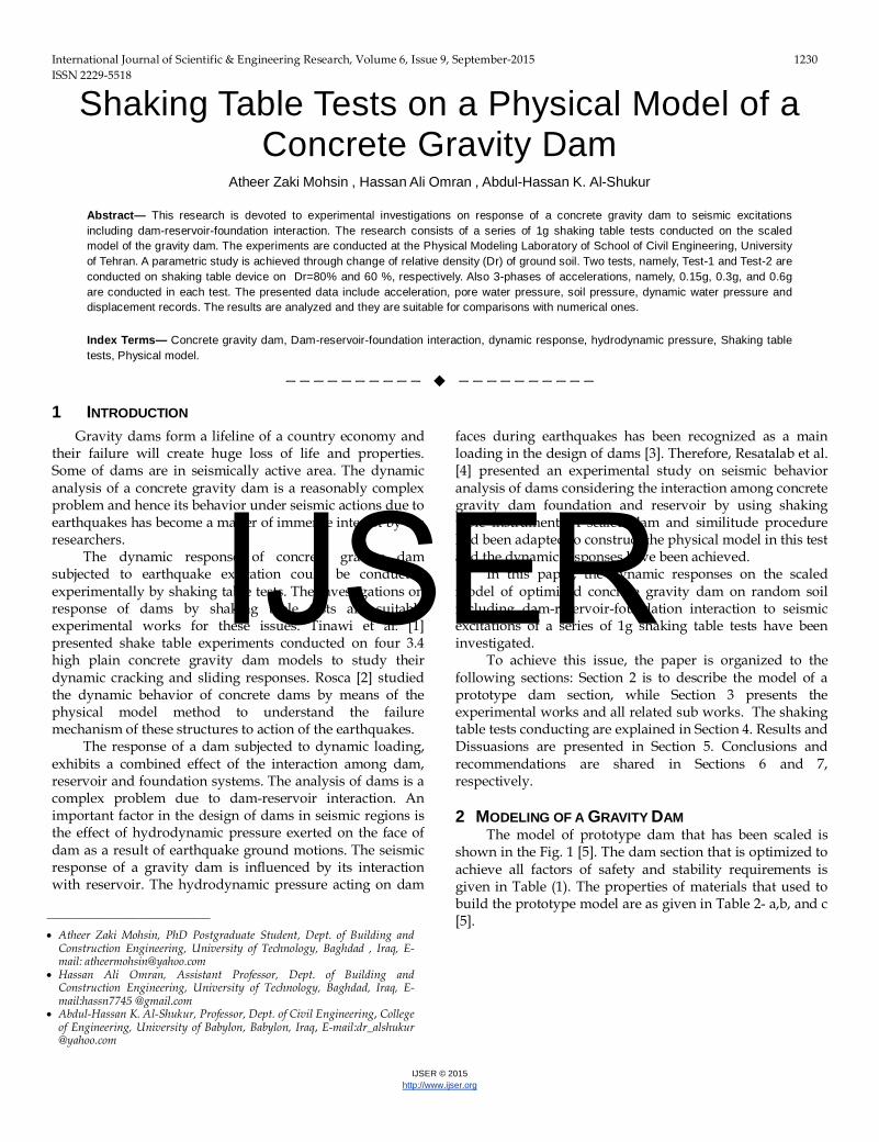
The model of prototype dam that has been scaled is shown in the Fig. 1 [5]. The dam section that is optimized to achieve all factors of safety and stability requirements is given in Table (1). The properties of materials that used to build the prototype model are as given in Table 2- a,b, and c [5]. ————————————————
• Atheer Zaki Mohsin, PhD Postgraduate Student, Dept. of Building and Construction Engineering, University of Technology, Baghdad , Iraq, E-mail: [email protected]
• Hassan Ali Omran, Assistant Professor, Dept. of Building and Construction Engineering, University of Technology, Baghdad, Iraq, E-mail:hassn7745 @gmail.com
• Abdul-Hassan K. Al-Shukur, Professor, Dept. of Civil Engineering, College of Engineering, University of Babylon, Babylon, Iraq, E-mail:dr_alshukur @yahoo.com
IJSER
International Journal of Scientific & Engineering Research, Volume 6, Issue 9, September-2015 1231 ISSN 2229-5518
IJSER © 2015 http://www.ijser.org
Fig. 1: Prototype Dam Model [5]
Table 1: Optimized Dam& Pile Sections [5]
Table 2: Properties of Materials [5]
3 EXPERIMENTAL WORKS
The experimental work consisted of two 1g shaking table tests. The tests are conducted using Shaking Table device of the Physical Modeling Laboratory of School of Civil Engineering, University of Tehran. This device has deck dimensions of 1.2m×1.8m and thanks to its actuator of 25kN capacity; it can apply horizontal base shakings of different forms up to 20Hz frequency and amplitude up to 1g. The tests are all designed, prepared and tested based on the procedure described in following parts.
a) Physical Model Design
The relation between the behavior of the scaled model and that of the prototype is defined by the scale similitude laws. In this research all required parameters are scaled based on [6] similitude law. Considering the limitations due to the dimensions of model container and the capacity of shaking table, a geometric scale of l =55 is used. Table (3) summarizes the scaling parameters used in this research. In this research, where the problem being studied is of a dynamic soil-water-structure interaction nature, the most critical parameters affecting the response of the model have been modeled. Therefore, the most important parameters
affecting the seismic response of the dam can be pointed out as below:
• Geometry of the dam and reservoir. • Natural period of the dam body. • Natural period of the soil that is affected by shear
wave velocity (VRsR) or shear modulus (G) of the soil. • Stress-strain behavior of the soil. • Stress-strain behavior of concrete used in dam body. • Behavior of soil in failure (c, φ). • Permeability of the soil. • Flexural stiffness of piles beneath the dam.
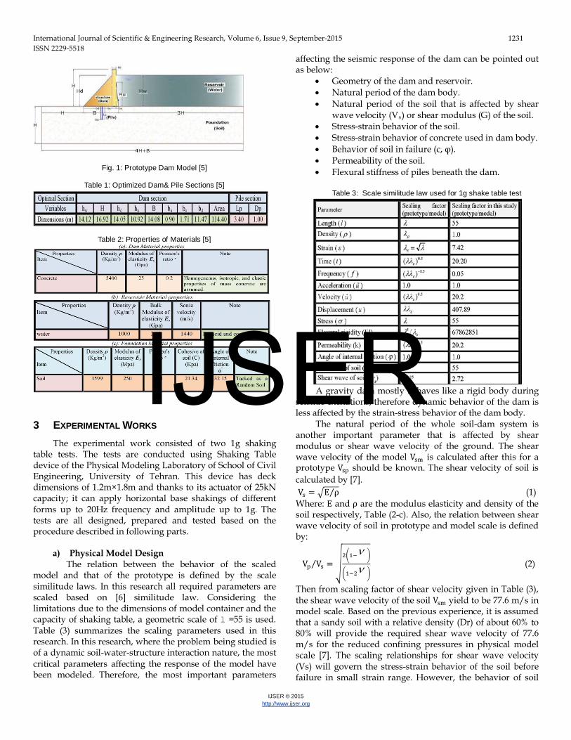
Table 3: Scale similitude law used for 1g shake table test
A gravity dam mostly behaves like a rigid body during
seismic excitations; therefore dynamic behavior of the dam is less affected by the strain-stress behavior of the dam body.
The natural period of the whole soil-dam system is another important parameter that is affected by shear modulus or shear wave velocity of the ground. The shear wave velocity of the model Vsm is calculated after this for a prototype Vsp should be known. The shear velocity of soil is calculated by [7]. Vs = �E ρ⁄ (1) Where: E and ρ are the modulus elasticity and density of the soil respectively, Table (2-c). Also, the relation between shear wave velocity of soil in prototype and model scale is defined by:
Vp Vs⁄ = �2�1−ν �
�1−2ν � (2)
Then from scaling factor of shear velocity given in Table (3), the shear wave velocity of the soil Vsm yield to be 77.6 m/s in model scale. Based on the previous experience, it is assumed that a sandy soil with a relative density (Dr) of about 60% to 80% will provide the required shear wave velocity of 77.6 m/s for the reduced confining pressures in physical model scale [7]. The scaling relationships for shear wave velocity (Vs) will govern the stress-strain behavior of the soil before failure in small strain range. However, the behavior of soil
IJSER
International Journal of Scientific & Engineering Research, Volume 6, Issue 9, September-2015 1232 ISSN 2229-5518
IJSER © 2015 http://www.ijser.org
y = 2.0729xR² = 0.9898
0
0.5
1
1.5
2
2.5
3
3.5
0 0.2 0.4 0.6 0.8 1 1.2 1.4 1.6
Defle
ction
(cm
)
Load (kg)
close to the failure was modeled by selecting type of soil scaling the cohesion (C) and the angle of internal (φ) of the soil in prototype scale given in Table (3-c).
Instead during the model construction, a 0.5cm thick clay blanket was created at the upstream side (i.e. below the reservoir) to decrease the seepage flow through the soil beneath the dam. Flexural rigidity of the concrete secant piles beneath the dam was also scaled as 1400MPa. In order to correctly scale the flexural rigidity of concrete piles, the material used to construct the pile in physical model should have a modulus of elasticity of about 1400MPa. As the modulus of elasticity of Teflon (Trade name for poly-tetra-fluoro-ethylene (PTFE) is very close to this value, it was decided to use model piles which are made of Teflon.
b) Material properties In this section the characteristics of basic materials (soil,
concrete…) that shall be used in tests will be discussed in the following subsections:
i. Soil The type of soil that is compatible with a prototype one
was used for construction of the ground in physical model which is sand with golden yellow appearance. A summary of the index properties of sand is provided in Table 4.
Table 4: Index properties of sand soil
As mentioned earlier, two shake table tests was performed in this research. The ground in these tests consisted of sand of two relative densities of 60% and 80%. In order to characterize the mechanical properties of the soil, two direct shear tests were performed on clean sand and an unconfined compression test was conducted on sandy soil with 3% clay. The final data of mechanical properties of soil used in physical model are summarized in Table 5.
Table 5: Summary of mechanical properties of soil used in physical model
As seen in Table (5), the angle of internal friction of sand used in physical model is 30.9˚ and 35.5˚ for relative density of 60% and 80%, respectively. These values are obtained by dividing the results of direct shear tests provided in Table (5) by a factor of 1.1. In this regard, it should be noted that it is commonly assumed that the angle of internal friction of soil in a plane strain condition (i.e. similar to the conditions in direct shear test) is about 10% higher than corresponding values in a fully 3D strain condition in reality (i.e. similar to triaxial test).
ii. Concrete
As mentioned before, since the behavior of gravity dam is expected to be similar to a rigid body during shaking, the strain-stress behavior and also the strength of the concrete was not scaled. As a result, the concrete mix design was only done in such a way to provide enough workability for the concrete to easily fill the formworks during casting. Materials used to create the concrete are fresh potable water, ordinary Portland cement (type 1) and sand aggregates. The specification of concrete mix design is W C⁄ = 0.89, Ww =314 kg m3⁄ , WC = 353 kg m3⁄ , Ws = 1506 kg m3⁄ . The results of compressional strength tests are provided that the average compressional strength of the concrete is 15.5 MPa for 28 days old specimens.
iii. Piles
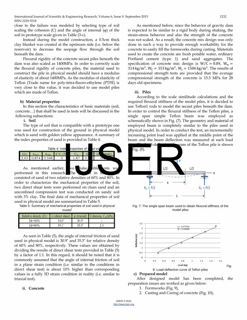
According to the scale similitude calculations and the required flexural stiffness of the model piles, it is decided to use Teflon1 rods to model the secant piles beneath the dam. In order to control the flexural stiffness of the Teflon piles, a single span simple Teflon beam was employed as schematically shown in Fig. (7). The geometry and material of employed beam is completely similar to the piles used in physical model. In order to conduct the test, an incrementally increasing point load was applied at the middle point of the beam and the beam deflection was measured at each load step. The load-deflection diagram of the Teflon pile is shown in Fig. (8).
Fig. 7: The single span beam used to obtain flexural stiffness of the model piles
Fig. 8: Load-deflection curve of Teflon piles
c) Prepared model After designed model has been completed, the
preparation issues are worked as given below: 1. Formworks (Fig. 9), 2. Casting and Curing of concrete (Fig. 10),
IJSER
International Journal of Scientific & Engineering Research, Volume 6, Issue 9, September-2015 1233 ISSN 2229-5518
IJSER © 2015 http://www.ijser.org
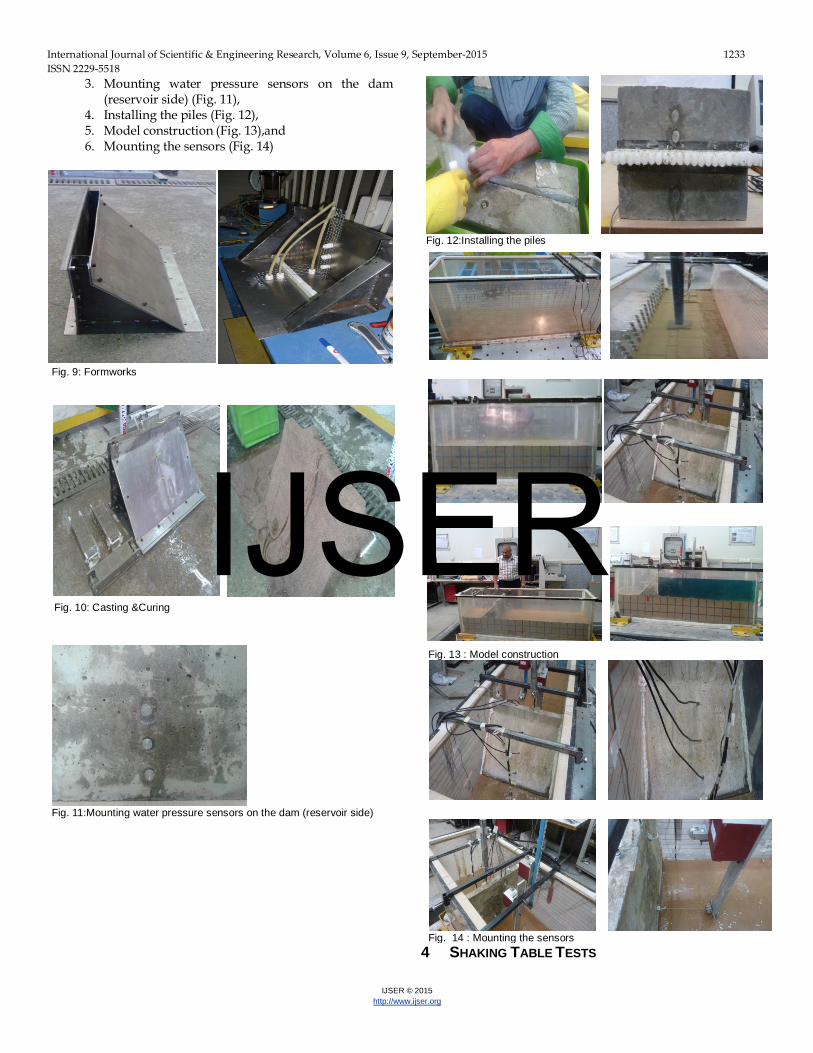
3. Mounting water pressure sensors on the dam (reservoir side) (Fig. 11),
4. Installing the piles (Fig. 12), 5. Model construction (Fig. 13),and 6. Mounting the sensors (Fig. 14)
Fig. 9: Formworks
Fig. 10: Casting &Curing
Fig. 11:Mounting water pressure sensors on the dam (reservoir side)
Fig. 12:Installing the piles
Fig. 13 : Model construction
Fig. 14 : Mounting the sensors
4 SHAKING TABLE TESTS
IJSER
International Journal of Scientific & Engineering Research, Volume 6, Issue 9, September-2015 1234 ISSN 2229-5518
IJSER © 2015 http://www.ijser.org
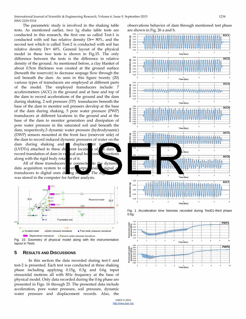
The parametric study is involved in the shaking table tests. As mentioned earlier, two 1g shake table tests are conducted in this research, the first one so called Test-1 is conducted with soil has relative density Dr= 80%, and the second test which is called Test-2 is conducted with soil has relative density Dr= 60%. General layout of the physical model in these two tests is shown in Fig.15. The only difference between the tests is the difference in relative density of the ground. As mentioned before, a clay blanket of about 0.5cm thickness was created at the ground surface (beneath the reservoir) to decrease seepage flow through the soil beneath the dam. As seen in this figure twenty (20) various types of transducers are employed at different parts of the model. The employed transducers include: 7 accelerometers (ACC) in the ground and at base and top of the dam to record accelerations of the ground and the dam during shaking, 2 soil pressure (TP) transducers beneath the base of the dam to monitor soil pressers develop at the base of the dam during shaking, 5 pore water pressure (PWP) transducers at different locations in the ground and at the base of the dam to monitor generation and dissipation of pore water pressure in the saturated soil and beneath the dam, respectively,3 dynamic water pressure (hydrodynamic) (DWP) sensors mounted at the front face (reservoir side) of the dam to record induced dynamic pressures of water on the dam during shaking and 3 displacement transducers (LVDTs) attached to three different locations of the dam to record translation of dam in vertical and horizontal directions along with the rigid body rotation of it.
All of these transducers are connected to the dynamic data acquisition system to convert output analog signal of transducers to digital ones during shaking. The digital data was stored in the computer for further analysis.
Fig. 15: Geometry of physical model along with the instrumentation layout in Tests 5 RESULTS AND DISCUSSIONS
In this section the data recorded during test-1 and test-2 is presented. Each test was conducted at three shaking phase including applying 0.15g, 0.3g and 0.6g input sinusoidal motions all with 8Hz frequency at the base of physical model. Only data recorded during the 0.6g phase are presented in Figs. 16 through 25. The presented data include acceleration, pore water pressure, soil pressure, dynamic water pressure and displacement records. Also, the
observations behavior of dam through mentioned test phase are shown in Fig. 26 a and b.
Fig. 1 :Acceleration time histories recorded during Test01-third phase 0.6g
-0.60
-0.40
-0.20
0.00
0.20
0.40
0.60
0 1 2 3 4 5 6
Acce
lera
tion
(g)
Time (Sec)
ACC1
-0.60
-0.40
-0.20
0.00
0.20
0.40
0.60
0 1 2 3 4 5 6
Acce
lera
tion
(g)
Time (Sec)
ACC2
-0.60
-0.40
-0.20
0.00
0.20
0.40
0.60
0 1 2 3 4 5 6
Acce
lera
tion
(g)
Time (Sec)
ACC3
-0.80-0.60-0.40-0.200.000.200.400.600.80
0 1 2 3 4 5 6
Acce
lera
tion
(g)
Time (Sec)
ACC4
-0.80-0.60-0.40-0.200.000.200.400.600.80
0 1 2 3 4 5 6
Acce
lera
tion
(g)
Time (Sec)
ACC5
-0.80-0.60-0.40-0.200.000.200.400.600.80
0 1 2 3 4 5 6
Acce
lera
tion
(g)
Time (Sec)
ACC6
-1.00
-0.50
0.00
0.50
1.00
0 1 2 3 4 5 6
Acc
eler
atio
n (g
)
Time (Sec)
ACC7
-1.50
-1.00
-0.50
0.00
0.50
1.00
1.50
0 1 2 3 4 5 6 7 8 9 10
Exce
ss p
ore
wat
er
pres
sure
(kPa
)
Time (Sec)
PWP1
-0.80-0.60-0.40-0.200.000.200.400.600.80
0 1 2 3 4 5 6 7 8 9 10
Exce
ss p
ore
wat
er
pres
sure
(kPa
)
Time (Sec)
PWP2
IJSER

International Journal of Scientific & Engineering Research, Volume 6, Issue 9, September-2015 1235 ISSN 2229-5518
IJSER © 2015 http://www.ijser.org
Fig. 17: Pore water pressure time histories recorded during Test01-third phase 0.6g
Fig. 18: Dynamic water pressure time histories recorded during Test01-third phase 0.6g
Fig. 19: Soil pressure time histories recorded during Test01-third phase 0.6g
Fig. 2: Displacement time histories recorded during Test01-third phase 0.6g
Fig. 21: Acceleration time histories recorded during Test-2-third phase 0.6g
-0.80-0.60-0.40-0.200.000.200.400.600.80
0 1 2 3 4 5 6 7 8 9 10
Exc
ess
pore
wat
er
pres
sure
(kP
a)
Time (Sec)
PWP4
-0.80-0.60-0.40-0.200.000.200.400.600.80
0 1 2 3 4 5 6 7 8 9 10
Exce
ss p
ore
wat
er
pres
sure
(kPa
)
Time (Sec)
PWP5
-2.00-1.000.001.002.003.004.005.006.00
0 1 2 3 4 5 6 7 8 9 10
Dyn
amic
soi
l pr
essu
re (k
Pa)
Time (Sec)
TP1
-2.00-1.000.001.002.003.004.005.006.00
0 1 2 3 4 5 6 7 8 9 10
Dyn
amic
soi
l pr
essu
re (k
Pa)
Time (Sec)
TP2
-0.50
0.00
0.50
1.00
1.50
0 1 2 3 4 5 6 7 8 9 10
Dis
plac
emen
t (cm
)
Time (Sec)
LVDT1
-0.50
0.00
0.50
1.00
1.50
0 1 2 3 4 5 6 7 8 9 10
Dis
pla
cem
ent (
cm)
Time (Sec)
LVDT2
-1.00
-0.80
-0.60
-0.40
-0.20
0.00
0.20
0 1 2 3 4 5 6 7 8 9 10
Dis
plac
emen
t (cm
)
Time (Sec)
LVDT3
-0.60
-0.40
-0.20
0.00
0.20
0.40
0.60
0 1 2 3 4 5 6 7 8
Acc
eler
atio
n (g
)
Time (Sec)
ACC1
-0.40-0.30-0.20-0.100.000.100.200.300.40
0 1 2 3 4 5 6 7 8
Acc
eler
atio
n (g
)
Time (Sec)
ACC2
-0.20-0.15-0.10-0.050.000.050.100.150.20
0 1 2 3 4 5 6 7 8
Acc
eler
atio
n (g
)
Time (Sec)
ACC3
-0.80-0.60-0.40-0.200.000.200.400.600.80
0 1 2 3 4 5 6 7 8
Acce
lera
tion
(g)
Time (Sec)
ACC4
-0.80-0.60-0.40-0.200.000.200.400.600.80
0 1 2 3 4 5 6 7 8
Acc
eler
atio
n (g
)
Time (Sec)
ACC5
-0.80-0.60-0.40-0.200.000.200.400.600.80
0 1 2 3 4 5 6 7 8
Acc
eler
atio
n (g
)
Time (Sec)
ACC6
-0.80-0.60-0.40-0.200.000.200.400.600.80
0 1 2 3 4 5 6 7 8
Acc
eler
atio
n (g
)
Time (Sec)
ACC7
-1.00
0.00
1.00
2.00
3.00
4.00
5.00
0 1 2 3 4 5 6 7 8 9 10
Exc
ess
pore
wat
er
pres
sure
(kP
a)
Time (Sec)
PWP1
IJSER
International Journal of Scientific & Engineering Research, Volume 6, Issue 9, September-2015 1236 ISSN 2229-5518
IJSER © 2015 http://www.ijser.org
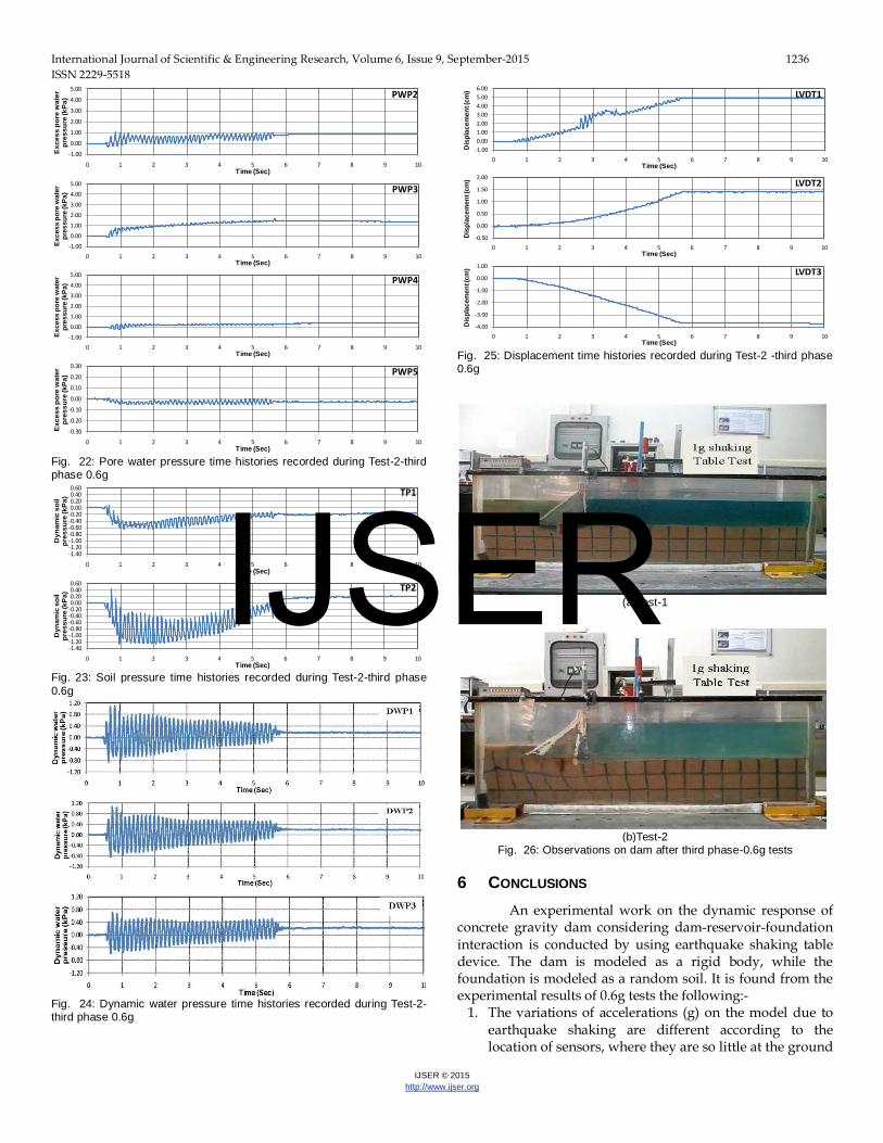
Fig. 22: Pore water pressure time histories recorded during Test-2-third phase 0.6g
Fig. 23: Soil pressure time histories recorded during Test-2-third phase 0.6g
Fig. 24: Dynamic water pressure time histories recorded during Test-2-third phase 0.6g
Fig. 25: Displacement time histories recorded during Test-2 -third phase 0.6g
(a)Test-1
(b)Test-2
Fig. 26: Observations on dam after third phase-0.6g tests
6 CONCLUSIONS An experimental work on the dynamic response of
concrete gravity dam considering dam-reservoir-foundation interaction is conducted by using earthquake shaking table device. The dam is modeled as a rigid body, while the foundation is modeled as a random soil. It is found from the experimental results of 0.6g tests the following:-
1. The variations of accelerations (g) on the model due to earthquake shaking are different according to the location of sensors, where they are so little at the ground
-1.00
0.00
1.00
2.00
3.00
4.00
5.00
0 1 2 3 4 5 6 7 8 9 10
Exc
ess
pore
wat
er
pres
sure
(kP
a)
Time (Sec)
PWP2
-1.00
0.00
1.00
2.00
3.00
4.00
5.00
0 1 2 3 4 5 6 7 8 9 10
Exce
ss p
ore
wat
er
pres
sure
(kPa
)
Time (Sec)
PWP3
-1.00
0.00
1.00
2.00
3.00
4.00
5.00
0 1 2 3 4 5 6 7 8 9 10
Exce
ss p
ore
wat
er
pres
sure
(kPa
)
Time (Sec)
PWP4
-0.30
-0.20
-0.10
0.00
0.10
0.20
0.30
0 1 2 3 4 5 6 7 8 9 10
Exc
ess
pore
wat
er
pres
sure
(kP
a)
Time (Sec)
PWP5
-1.40-1.20-1.00-0.80-0.60-0.40-0.200.000.200.400.60
0 1 2 3 4 5 6 7 8 9 10
Dyn
amic
soi
l pr
essu
re (k
Pa)
Time (Sec)
TP1
-1.40-1.20-1.00-0.80-0.60-0.40-0.200.000.200.400.60
0 1 2 3 4 5 6 7 8 9 10
Dyn
amic
soi
l pr
essu
re (k
Pa)
Time (Sec)
TP2
-1.000.001.002.003.004.005.006.00
0 1 2 3 4 5 6 7 8 9 10
Dis
plac
emen
t (cm
)
Time (Sec)
LVDT1
-0.50
0.00
0.50
1.00
1.50
2.00
0 1 2 3 4 5 6 7 8 9 10
Dis
plac
emen
t (cm
)
Time (Sec)
LVDT2
-4.00
-3.00
-2.00
-1.00
0.00
1.00
0 1 2 3 4 5 6 7 8 9 10
Dis
plac
emen
t (cm
)
Time (Sec)
LVDT3
IJSER

International Journal of Scientific & Engineering Research, Volume 6, Issue 9, September-2015 1237 ISSN 2229-5518
IJSER © 2015 http://www.ijser.org
due to absorption of impact wave of acceleration by the saturation soil particles and at the boundary of reservoir upstream U/S of dam due to effect of interaction in-between reservoir and foundation. In other hand, these variation increase from base of ground to the crest of dam.
2. There are obvious variations of pore water pressure under dam.
3. The variations on soil pressure at the base of dam are different in-between heel and toe.
4. The most variation of hydrodynamic pressure increase with depth of reservoir.
5. The displacements in the crest and bottom of dam indicate that the sliding and overturning are desired.
6. The liquefaction phenomenon is observed in saturated loss sand soil.
7 RECOMMENDATIONS
1. From the results and observations of tests, it is recommended the following:
2. Avoidance of construct this type of dam on random soil at region affected by seismic zone of PGA=0.6g (Category V of moderate shaking and 4.5 of Richter Scale ) and more, but it can construct this type as located on region affected by seismic zone of PGA= (0.01‒0.4)g (Category I, II-III, and IV as Not felt, weak, and light shaking respectively that ranged 1-4 of Richter Scale).
3. Construct blanket of clay layer about 30 cm upstream dam to reduce seepage flow through foundation.
4. Construct sheet of secant piles beneath dam to reduce seepage, pear the weight of dam, and to prevent both sliding and overturning.
5. Avoidance of construct concrete gravity dam founded on saturated sand soil under effects of seismic zone due to liquefaction effect.
ACKNOWLEDGMENT The authors wish to thank Dr. Ghalandarzadeh and Dr. Kavand for allowableling to achieve the tests of this paper in the Physical Model Laboratory, Civil Engineering department, College of Engineering, University of Tehran. Also, continually thinks introduce to the staff of this laboratory to their encouragements and assessments to complete the works. REFERENCES [1] R. Tinawi, P. Leger, and M. Lecler ,“ Seismic Response of
Gravity Dams-Correlations between Shake Table Tests and Numerical Analyses ”, Technical Journal of Engineering and Applied Sciences (TJEAS), Volum 03, issue 16, PP. 1756-1762. 2000.
[2] B. Rosca, “Physical Model Method for Seismic Study of Concrete Dams”, Buletinul Institutului Politehnic Din Iasi, Voulm 4, Issue 3, PP. 57-76, October 12-17, 2008.
[3] M. Pasbani-Khiavi , A.R.M. Gharabaghi, and K. Abedi, “Dam-Reservoir Interaction Analysis Using Finite Element Model”, The 4th World Conference on Earthquake Engineering, October 12-17, 2008.
[4] S. Resatalab, R. Attarnejad,and A. Ghalandarzadeh,“ Experimental investigation on interaction of concrete gravity dam-reservoir-foundation on shaking table”, Technical Journal of Engineering and Applied Sciences (TJEAS), volum 03, issue 16, PP. 1756-1762, 2013.
[5] A. Z. Mohsin , H. A. Omran, and A.-H. K. Al-Shukur, “Optimal Design of Low Concrete Gravity Dam on Random Soil Subjected to Earthquake Excitation”, ITISET, vol. 4, no.9, PP. 8961-8973, September,2015.
[6] S. Iai, “Similitude for shaking table tests on soil–structure–fluid model in 1g gravitational field”, Soils and Foundations, vol. 29, no.1, pp. 105–118, 1989.
[7] K. Rao, “Foundation Design: Theory and Practice”, John Wiley and sons (Asia) Pte, pp. 9-48, 2011.
IJSER

International Journal of Scientific & Engineering Research, Volume 6, Issue 9, September-2015 1238 ISSN 2229-5518
IJSER © 2015 http://www.ijser.org
IJSER