SHAHPURKANDI DAM PROJECT
132
SHAHPURKANDI DAM PROJECT BID DOCUMENT FOR CONSTRUCTION OF AQUEDUCT OVER SUKHRAL KHAD AND ADJOINING NALLAH INCLUDING CONSRUCTION OF BARREL,FLAIR- IN-& FLAIR-OUT-WALLS & PROTECTION WORK FROM RD ± 265.8M TO ± 819.0M OF PROPOSED RAVI CANAL ON EPC MODE VOLUME-II WATER RESOURCES DEPARTMENT GOVERNMENT OF PUNJAB
Transcript of SHAHPURKANDI DAM PROJECT

SHAHPURKANDI DAM
PROJECT
BID DOCUMENT FOR
CONSTRUCTION OF AQUEDUCT OVER SUKHRAL KHAD AND ADJOINING NALLAH INCLUDING CONSRUCTION OF BARREL,FLAIR-IN-& FLAIR-OUT-WALLS & PROTECTION WORK FROM RD ± 265.8M TO ± 819.0M OF PROPOSED RAVI CANAL ON EPC MODE
VOLUME-II
WATER RESOURCES DEPARTMENT
GOVERNMENT OF PUNJAB
SUMMARY SHEET OF
BID DOCUMENTS
Volume Section Description Page No.
No. No.
II 10 Technical Specifications 1-117
General Arrangement Drawings and Site 118-122
II 11 Investigation Data

Volume –II
Section – 10
Technical Specifications

Index
Para Description Page No.
No.
General 1
1 Specifications for RCC Items of Aqueduct 2
1. Material for Concrete 2
1.1 Composition of Concrete 2
1.2 Cement 2-3
1.3 Admixtures 4-5
1.4 Water 6-7
1.5 Sand 7
1.6 coarse Aggregate 10-11
1.7 Production of Sand and coarse Aggregate 12-13
2. Batching and Mixing of Aggregate 13
2.1 Batching 13-16
2.2 Mixing 16-17
3. Quality of Concrete 19
3.1 Maximum size of Aggregate 19-20
3.2 Mix Proportions 20
3.3 Water -Cement Ratio 20-23
3.4 Consistency 23-24
3.5 Test 24-26
3.6 Designation and classification of concrete Mixes 27-28
3.7 Porous Concrete 28
4. Tolerances For Concrete Construction 29
4.1 General 29-30
4.2 Tolerances for structures 30

4.3 Tolerance in intake structures spillway etc. 31
4.4 Lining of Approach etc. 33-34
4.5 Monolithic siphons and culverts 34
4.6 Anchors, Bends etc. 34
4.7 Concrete Roads, Yards etc. 34-35
4.8 Tolerance for placing reinforcement steel 35
5 Forms for Concrete 40
5.1 General 36-37
5.2 Forms sheathing and lining 37-38
5.3 Plywood form lining 38
5.4 Tongue and groove Sheathing 38
5.5 Uniformity of forming material 38-39
5.6 Forms for warped surface designated for F4 finish 39
5.7 Form Ties 39-40
5.8 Cleaning and oiling forms 40
5.9 Removal of forms 40-41
6 Placing of Concrete 41
6.1 Preparations for placing concrete 41
6.2 Placing of concrete 44
6.3 Placing Temperature 49-50
6.4 Weather Conditions 50
7 Finishes and Finishing of Concrete 50
7.1 General 50-51
7.2 Finishes for formed surfaces 51
7.3 Finishes for unformed surfaces 53-55
7.4 Maximum allowances of irregularities 55-56

7.5 Finishing Recesses 56
8 Protection, Curing and Repair of Concrete 56
8.1 Protection of concrete 56
8.2 Curing of concrete 56-58
8.3 Repair of concrete 59-60
8.4 Dry pack mortar 60-61
8.5 Expensive concrete or mortar 61-62
9 Steel Reinforcement 62
9.1 Scope 62
9.2 Applicable publications 62-63
9.3 Materials 63
9.4 Fabrication 63
9.5 Placing in position 63-64
2 Specifications for Items Other Than RCC for Aqueduct 65
10 Foundation excavation 65
10.1 Scope 65
10.2 Setting out 65
10.3 Clearing 65
10.4 Stripping 65
10.5 Access and haulage roads 66
10.6 Excavation –basic requirements 66-67
10.7 Methods of excavation 67
10.8 Disposal of excavated material 67
10.9 Dewatering 67
11 Backfill 68
11.1 Scope 68

11.2 Location of backfill and production of fill material 68
11.3 Preparation of foundation surface and placement 68
11.4 Gradation requirements 69
11.5 Compaction 69-70
11.6 Subsoil water level 70
12 Water Profing Seals & Joint 70
12.1 Construction Joints 70
12.2 Expansion Joints 70
12.3 Asphalt seals 71-72
12.4 Water swelling rubber sealing material 73-74
12.5 P.V.C water stops 74-75
Annexure –A, Test and Test procedure for PVC Water stops 81-82
3. Earthwork Specifications for Canal 83
1.0 Scope 83
2.0 Planning 83
3.0 Setting Out 83-84
4.0 Clearing 84
5.0 Stripping Loose Material 84
6.0 Excavation 84
6.1 General 84-85
6.2 Excavation - Basic Requirements 85-86
6.3 Method of Excavation 86
6.4 Rock Excavation 86-87
6.5 Disposal of Excavated Material 87
6.6 Preparation of Sub grade 87-88
7.0 Filling Reaches 88

7.1 Definition of Canal Section 88
7.2 Definition of Materials 89-89
7.3 Gradation Requirements 89
7.4 Sources of Fill Materials 89
7.5 Production of Fill Material 89-90
7.6 Fill Placement 90
8.0 Quality Control 94
8.1 General 94
8.2 Field Tests 94-95
8.3 Laboratory Tests 95
8.4 The Data of Various Tests 96
8.5 Location and Periodicity of Field Tests 96-97
9.0 Compaction Equipment 97
10.0 Miscellaneous 98
Appendix-1 100
Appendix-2 101
5. Specifications for Cement Concrete Lining 102
1.0 Scope 102
2.0 Terminology 102
2.1 Compaction 102
2.2 Consolidation 102
2.3 Construction Joint 102
2.4 Expansion Joint 102
2.5 Lip cutting 102
2.6 Slip Form 103
2.7 Sub Grade 103
3.0 Materials 103

3.1 Cement 103
3.2 Aggregates 103
3.3 Water 103
4.0 Preparation of Sub grade 103
4.1 General 103-104
4.2 Preparation of Sub grade in Expansive Soils 105
4.3 Preparation of Sub grade consisting of Rock 105-106
4.4 Preparation of Sub grade consisting of Earth 106
4.5 Anti Salt Treatment 107
5.0 Laying of Concrete Lining 108
5.1 General 108
5.2 Cement Concrete 108
5.3 Slump 108
5.4 Air Entraining Admixture 108-109
5.5 Laying of Sleepers 109
5.6 Laying of Slabs 109
5.7 Mixing 109
5.8 Transporting 109-110
5.9 Placing 110
5.10 Finishing 111-112
5.11 Curing 112
5.12 Testing 112
6.0 Surface Drainage 112-113
7.0 Joints 113
7.1 Expansion Joints 113
7.2 Construction / Contraction Joints 113-114
7.3 Filler 114

5. Specifications for Protection work 115
1.0 Wire Crates 115
2.0 Boulder 115
6. Detail of Drawings & Site investigation Data 118-122

1
GENERAL
The Contractor shall adhere to various elevations (Reduced Levels) as
mentioned in the drawings provided with the bid documents except for
lowest/bottom levels shown in station layout drawings (as these are
indicative only) for which detailed structural design is to be carried out by
the contractor.
All Hydraulic/Structural design shall confirm to latest IS Codes.
The latest IS codes shall supersede the specifications mentioned in the bid
documents, however concurrence for the same shall be obtained from
engineer in charge before making any change in specifications.
The contractor should take other parameters as shown in the relevant
drawings for Structural and Hydraulic design. In case, the Contractor needs
any clarification, he can refer the matter to the Chief Engineer.

2
1) Specifications for RCC Items of Aqueduct
SPECIFICATIONS FOR CEMENT
CONCRETE PURPOSE
These specifications for Cement Concrete have been framed to provide
uniformity in the construction of works of Aqueduct. These specifications are to be
adopted both by the Employer and the executing agency.
The specifications proposed are based on the specification 4-AS:
“Specifications for Cement Concrete General” issued by HDO. Suitable modifications
however have been incorporated keeping in view the latest practices. Whenever
reference to Indian Standards are given in these Specifications, these refer to the
latest edition of the relevant Indian Standard.
MATERIALS FOR CONCRETE
1.1 Composition of Concrete
Concrete shall be composed of cement, sand, coarse aggregate, water and
other admixtures, all well mixed and brought to the proper consistency.
1.2 Cement
1.2.1 Specifications
Cement for concrete, mortar and grout shall be ordinary or low heat Portland
cement conforming to relevant IS Code. In case Portland pozzolana cement is to be
used, the same shall conform to IS: 1489 Part-1: 2015 (or latest revision)
“Specification for Portland pozzolana cement, fly ash based,” and must not contain
any other pozzolanic material except fly ash. Fly ash for use as pozzolana shall
conform to IS: 3812-1981 “Specification for fly ash for use as pozzolana and
admixture. (First Revision) Reaffirmed 1999”
A certificate should be obtained from the manufacturer for each consignment
indicating the percentage of fly ash used for that particular batch and certifying that fly
ash conforming to relevant Indian Standards have been used in the manufacture of
Portland pozzolana cement.

3
The use of Portland pozzolana cement should be limited to concrete mixes up
to a Grade of M-30. Only ordinary Portland cement should be used for mixes richer
than M-30 and for works where pre-stressed concrete is employed.
1.2.2 Transportation of Cement
Cement shall be transported to Project site in bulk, cartload lots or in bags as
approved by the Employer. Cement shall be checked on the job for contamination or
partial setting due to any accidental exposure to moisture during transit.
1.2.3 Storage of Cement
Storage bins for bulk cement shall be weather tight and shall be so constructed that
there will be no dead storage. If, in the opinion of the S.E. / Director, Inspection and
Control, there is reason to believe that any dead storage exists, bins shall be emptied
completely at least every 120* days. Handling and storage facilities shall be such that
no cement is stored before use for more than 120* days. Should any cement be
unavoidably kept in storage longer than 120* days, it shall be tested and, if found
defective, shall be condemned. Cement stored beyond 180 days shall not be used.
In case of storage of cement in bags, the cement shall be stored in a dry and
water-tight structure with adequate provisions for the prevention of absorption of
moisture. All storage facilities shall be subject to the approval of S.E./Director,
Inspection & Control or his authorized agent and shall be such as to permit easy
access for inspection and identification. The cement which has been stored for 60
(sixty) days or more, shall be used before using cement of lesser age. Cement stored
beyond 120* days from the date of manufacture by the manufacturer, shall be tested
and rejected if found defective in anyway. Ordinary Portland cement and Portland
pozzolana cement shall be stored separately.
Cement should be stored at least 18 inches (45 cm) above the natural surface
of the ground. Cement shall not be stored in contact with walls. Cement should be
stacked not more than ten layers high to prevent bursting of bags in the bottom layers
and formation of clods.
* If in the opinion of S.E./ Director, Inspection & Control, it is found that storage has not been done as per specifications laid out here or relevant IS Code ,the period may be reduced to 90 days or less.

4
1.2.4 Inspection
Sampling and testing of cement shall be done in accordance with relevant
Indian Standard Specifications. In case of Portland pozzolana cement, quality control
should be more effectively enforced. Immediately on receipt of each consignment of
cement, tests should be carried out for its various properties as per relevant Indian
Standard Codes. The 3 days, 7 days and 28 days compressive strength of Portland
pozzolana cement should be same as specified in Para 7.4.1 of IS: 1489 Part 1: 2015
(or latest revision) which should be tested in the project laboratory before use. If test
results do not conform to IS standards, the matter should be taken up with the agency.
No cement shall be used until notice has been given by the S.E./ Director, Inspection
& Control or his authorized agent that test results conform to IS requirements. If the
tests prove that cement which has been delivered is unsatisfactory, it shall be
promptly removed from the site of work and should not be used on any work on the
project.
1.2.5 Vibration
It should be ensured that a heavy duty vibrating screen is in place over the
discharge into the air slide. The screen size shall be 4 mm. All cement or foreign
material retained on the screen shall be wasted.
1.2.6 Testing of cement at site
The tests to be conducted on site by the Employer on a routine basis are:
- Time of set
- False set
- Compressive strength
- Fineness
1.3 Admixtures
1.3.1 Accelerators
The early strength of concrete can be increased by inclusion of an accelerator,
such as calcium chloride, in the concrete mix. However, such admixtures shall be
used only upon written approval of the Employer covering the type, amount and
location of use. The use of calcium chloride shall not be permitted in concrete in which
reinforced steel/any other metal work is to be embedded. The amount of

5
accelerator used shall be no more than that necessary to produce the desired results.
Calcium chloride shall not be used in excess of 2% by weight of the cement. Calcium
chloride shall be measured accurately and shall be added to the batch in solution in a
portion of the mixing water. Use of calcium chloride in the concrete shall in no way
affect compliance with the requirements of these specifications governing protection
and curing of the concrete. Special precautions shall be taken to avoid delay in
handling and placing of concrete when accelerator are used.
Accelerating admixtures, whenever used, shall conform to the requirements of
IS: 9103-1999 reaffirmed 2018 (or latest revision) “Specifications for Admixtures for
Concrete”.
1.3.2 Air-entraining Agents
An air-entraining agent shall be used in all concrete. The agent used shall
conform to IS: 9103-1999 reaffirmed 2018 (or latest revision), “Specifications for
Admixtures for Concrete”, except that the limitation and test on bleeding by concrete
containing the agent shall not apply. The agent shall be of uniform consistency and
quality within each container. The air-entraining admixtures shall be added to the
batch in solution in a portion of the mixing water. The solution shall be maintained at
uniform strength and shall be batched by means of a mechanical batcher capable of
accurate measurement of the agent, throughout the batch during the specified mixing
period. When calcium chloride is being used in concrete, the portion of the mixing
water containing the air-entraining agent shall be introduced separately into the mixer.
The amount of air-entraining agent used in each concrete mix shall be such as
will affect the entrainment of the percentage of air in the concrete as discharged from
the mixer in accordance with the following table:
Coarse Aggregate max.
Size in mm
Total air percent, by Volume, of concrete
20
40
80
5.0±1
4.0±1
3.0±1

6
The quantity of air as tabulated above shall be changed as directed by the
Employer, whenever such change is deemed necessary to meet the varying
conditions encountered during construction.
1.3.3 Water-reducing, Set-retarding Agent
The water reducing, set-retarding agent, if its use as an admixture is approved,
shall conform to IS:9103-1999 reaffirmed 2018 (or latest revision). The agent shall be
of uniform consistency and quality within each container and from procurement to
procurement.
The amount of water-reducing, set-retarding agent used in each concrete batch
shall be determined by laboratory tests.
The water-reducing, set-retarding agent shall be measured for each batch by
means of a reliable mechanical dispenser. The agent, in a suitably diluted form, may
be added to water containing air-entraining agent for the batch, provided the agents
are compatible with each other. The agent can also be introduced separately to the
batch in a portion of the mixing water.
1.3.4 Banning of Powdered Admixtures
Powdered admixture shall not be used nor any admixture which requires any
processing other than measurement prior to use.
1.4 Water
The water used in concrete, mortar and grout shall be clean and free from
objectionable quantities of silt, organic matter, alkalis, acids, oil or other impurities
which are injurious to concrete. Potable waters are generally considered satisfactory
for mixing and curing concrete.
Where water can be shown to contain any sugar or an excess of acid, alkali or
salt, the Employer may refuse to permit its use. The following concentrations
represent the maximum permissible values of sugar, acid, alkali or salt:
a. To neutralize 200 ml sample using phenolphthalein as an indicator, it should not require > 2 ml of 0.1 normal NaOH
b. To neutralize 200 ml sample using mixed indicator, it should not require > 10 ml of 0.1 normal HCl.

7
c. Percentage of solids should not exceed the following:-
Organic 0.02 percent
Inorganic 0.30 percent
Sulphates 0.05 percent.
Alkali Chlorides 0.10 percent.
In case of doubt the Employer may require that concrete mixed with water
proposed to be used should not have a compressive strength lower than 90% strength
of the concrete mixed with distilled water.
1.5 Sand
1.5.1 General
The term “sand” is used to designate aggregate in which the maximum size of
particles is 4.75 mm. Sand for concrete, mortar and grout shall be natural sand or
crushed rock or a mixture of natural sand and crushed rock. Sand, as delivered to the
batching plant, shall have reasonably uniform and stable moisture content.
1.5.2 Quality
Sand from natural sources shall consist of siliceous material having hard,
strong, durable, uncoated particles free from injurious amounts of dust, lumps, soft or
flaky particles, shale, alkali, organic matter, loam, mica and other deleterious
substances.
Manufactured sand shall consist of crushed stone, gravel or other inert
materials having hard, strong, durable, uncoated particles, free from injurious amounts
of dust, lumps, soft or flaky particles and other deleterious substances.
The maximum percentage of deleterious substances in the sand, as delivered
to the mixer, shall not exceed the following values.
S. No.
Deleterious substance
Fine aggregate percentage by weight max.
Uncrushed Crushed
I
II
Coal and lignite.
Clay Lumps
1.00
1.00
1.00
1.00

8
III
IV
V
VI
Material Finer than 75-μm IS Sieve
Soft fragments.
Shale
Total of percentages of all the deleterious materials (except mica) including S. No. (I) to (V) for col. 3 and S. No. i to ii for col 4 only
3.00
--
1.00
5.00
15.00
---
--
2.00
NOTES:
1. The presence of mica in the fine aggregate has been found to reduce
considerably the durability and compressive strength of concrete and further
investigations are underway to determine the extent of the deleterious effect
of mica. It is advisable, therefore, to investigate and make suitable
allowances for the possible reduction in the strength of concrete or mortar.
2. The aggregate shall not contain harmful organic impurities (tested in
accordance with IS:2386 Part II-1963 reaffirmed 2016) in sufficient
quantities to affect adversely the strength or durability of concrete. A fine
aggregate which fails in the test for organic impurities may be used provided
that when tested for the effect of organic impurities on the strength of
mortar, the relative strength at 7 and 26 days reported in accordance with
IS:2386 Part-II-1963 is not less than 95%.
3. The sum of the percentages of all deleterious substances shall not exceed
5% by weight. Sand producing a colour darker than the standard in the
colorimetric test for organic impurities (Designation 14) may be rejected.
Sand having a specific gravity (Designation 9, saturated surface-dry-basis)
of less than 2.50 may be rejected. The sand may be rejected if the portion
retained on No. 50 ASTM Screen (IS Sieve 300 micron) when subjected to
5 cycles of the sodium sulphate tests for soundness (Designation 19),
shows a weighted average loss of more than 10% by weight. The
designations in parentheses refer to methods of tests described in the
U.S.B.R. “Concrete Manual”.

9
1.5.3 Grading
The sand, as batched, shall be well graded and when tested by means of
Standard Screen Conforming to IS:460-1985, shall conform to following limits:-
IS Sieve as per IS:460-
1985
Percentage passing for
Grading Grading Grading Grading Zone-I Zone-II Zone-III Zone-IV
10 mm
4.75 mm
2.36 mm
1.18 mm
600 micron
300 micro
n
150 micron
100
90-100
60-95
30-70
15-34
5-20
0-10
100
90-100
75-100
55-90
35-59
8-30
0-10
100
90-100
85-100
75-100
60-79
12-40
0-10
100
95-100
95-100
90-100
80-100
15-50
0-15

10
NOTES: For crushed stone sand the permissible limit on IS sieve 0.150 mm is
20%
1. Fine aggregates complying with the requirements of any grading Zone in
this table is suitable for concrete but the quality of concrete produced will
depend upon a number of factors including proportions.
2. Where concrete of high strength and good durability is required, fine
aggregate conforming to any one of the four grading Zones may be
used, but the concrete mix should be properly designed.
3. It is recommended that fine aggregate conforming to grading Zone IV
should not be used in reinforced concrete unless tests have been made
to ascertain the suitability of proposed mix proportions.
In addition to the grading limits shown above, the sand as delivered to the
mixer shall have a fineness modulus of not less than 2.20.
1.6 Coarse Aggregate
1.6.1 General
The term “Coarse Aggregate” for the purposes of these specifications
designates aggregate of sizes ranging from 4.75 mm to 80 mm or any size or range of
sizes within such limits. The coarse aggregate shall be reasonably well graded within
the nominal size ranges as specified later in this paragraph.
Coarse aggregate for concrete shall consist of natural gravel or crushed rock or
a mixture of natural gravel and crushed rock and shall conform to either IS:383 - 2016
(or latest revision) “Specification for Coarse and Fine Aggregate from Natural Sources
for Concrete”.
Manufactured aggregate shall consist of crushed stone which is produced by
the artificial crushing of rocks, boulders or large cobble stones. Coarse aggregate, as
delivered to the batching plant, shall have uniform and stable moisture content.
1.6.2 Quality
The coarse aggregate, natural or manufactured, shall consist of clean, hard,
dense, durable, uncoated rock fragments. The percentage of deleterious substances
in any size of coarse aggregate, as delivered to the mixer, shall not exceed the
following values:-

11
Coarse aggregate % by weight
S. Deleterious substance
max.
No.
Uncrushed
crushed
i Coal and lignite. 1.00 1.00
ii Clay Lumps 1.00 1.00
iii Material Finer than 75 micron 3.00 3.00 Sieve
iv Soft fragments. 3.00 ---
V Shale -- --
vi Total of percentages of all 5.00 5.00 deleterious materials (Except mica) including S. No. (i) to (v) for col. 3 and 4.
NOTES :

12
The aggregate shall not contain harmful organic impurities (tested in
accordance with IS:2386 Part II-1963) in sufficient quantities to affect adversely the
strength or durability of concrete. The sum of the percentage of all deleterious
substances in any sizes, as delivered to the mixer, shall not exceed 5% by weight.
Coarse aggregate may be rejected if it fails to meet the specifications of IS: 383 - 2016
and following test requirements:-
Specific gravity (Designation 10) - if the specific gravity (saturated surface-
dry basis) is less than 2.50.
The designation in parentheses refers to methods of tests described in the U.S.B.R.
“Concrete Manual”.
1.6.3 Separation
The coarse aggregate shall be separated into nominal sizes and shall be
graded or batched (U.S.B.R. “Concrete Manual” Designation-5) as follows:
Designation of size
20 mm
40 mm
80 mm
Nominal size range Min % retained on screens
indicated
4.75 mm to 20 mm 50% on 10 mm
30 mm to 40 mm 25% on 31.5 mm
40 mm to 80 mm 25% on 63 mm
The screen sizes correspond to ASTM Standards (ASTM Designation 11.61) and in mm to Indian Standards (IS:460-1985 reaffirmed 2018).
Grading of coarse aggregate and all-in aggregate shall conform to Table 2 &
Table 5 respectively of IS: 383 - 2016.
1.7 Production of Sand and Coarse Aggregate
1.7.1 Source of Aggregate
Sand and coarse aggregate for concrete, sand for mortar and grout and raw
materials for manufacturing sand and coarse aggregate shall be obtained from any
approved source. The suitability of the available material will be established by
obtaining samples from the source and subjecting them to prescribed tests in the
laboratory.

13
1.7.2 Developing Aggregate Deposits
The area of the deposits from which aggregates are to be produced shall be
carefully cleared of trees, roots, brush, sod, soil, unsuitable sand, gravel and other
objectionable matter.
1.7.3 Processing Raw Materials
Processing of the raw material from sand and gravel deposits will include
quarrying, crushing, screening, washing and blending, supplemented by such other
processing operations as may be necessary to produce sand and coarse aggregate
meeting the requirements of paragraphs 1.5 & 1.6.
2. BATCHING AND MIXING OF CONCRETE
2.1 Batching
2.1.1 General
The batching equipment shall be such as to accurately determine and control
the prescribed amounts of various constituents materials for concrete, viz. water,
cement, admixtures, sand and each size of coarse aggregate entering each batch of
concrete shall be determined by separate weighing. Cumulative batching may be
adopted for small jobs with the approval of the Employer. For further details, see
clause 10.2 of IS: 456-2000 reaffirmed 2016 and clause 4.6 of IS: 457-1957 reaffirmed
2014. Batching plant should confirm to IS 4925-1968.
Necessary precautions should be taken to ensure adjustments to be applied for
the water absorption and surface moisture of aggregate. For determination of these
adjustments, reference may be made to IS: 2386 (Part III) – 1963 reaffirmed 2016,
“Methods of test of aggregate for concrete: Part III specific gravity, density, voids,
absorption and bulking.”
Batch bins shall be constructed so as to be self-cleaning during drawdown and
the bins shall be drawn down until they are practically empty at least 3 times per week.
Materials shall be deposited in the batch bins directly over the discharge gates. The
40 mm and 80 mm coarse aggregate shall be deposited in the batcher bins through
effective rock ladders when the distance through which the aggregates would fall is
greater than 120 cm. To minimizes breakages, the method used in transporting the
aggregate from a higher to a lower elevation shall be such that the aggregate will

14
roll and slide with a minimum amount of free fall. Equipment for conveying batched
materials from the batch hopper or hopper to and into the mixer shall be such that
there will be no spillage of the batched materials or overlap of batches. Equipment for
handling Portland cement in the batching plant shall be such as to prevent noticeable
increase of dust in the plant during the discharging of each batch of material. If the
batching and mixing plant is enclosed, exhaust fans or other suitable equipment for
removing dust shall be installed.
When bulk cement and aggregates are hauled from a central batching plant to
the mixers, the cement for each batch shall either be placed in an individual
compartment which, during transit, will prevent the cement from intermingling with the
aggregates and will prevent loss of cement, or be completely enfolded in and covered
by the aggregates by loading the cement and aggregate for each batch
simultaneously into the batch compartment. Each batch compartment shall be of
sufficient capacity to prevent loss in transit and to prevent spilling and intermingling of
batches as compartments are being emptied. If the cement is enfolded in aggregates
containing moisture, and delays occurs between filling and emptying the
compartments, extra cement shall be added to each batch in accordance with
following schedule :-
Hour of contact between cement and wet aggregate
Additional cement required
0 to 2
2 to 3
3 to 4
4 to 5
5 to 6
Over 6
0 percent
5 percent
10 percent
15 percent
20 percent
Batch will be rejected
2.1.2 Equipment
The weighing and measuring equipment shall conform to the following:-
IS:2722-1964 reaffirmed 2016 “Specifications for Portable Swing Weigh Batchers for

15
Concrete (Single and Double Bucket Type)” or IS:1791 - 2020 “General Requirements
for Batch Type Concrete Mixers”.
a. The construction and accuracy of the equipment shall conform to the applicable
requirements for such equipment, except that an accuracy of 0.4% over the
entire range of equipment will be required as per IS: 4925-2004 reaffirmed 2015
“Specifications for Concrete Batching and Mixing Plant.” Standard test weights
and any other auxiliary equipment shall be available for checking operating
performance of each scale. Periodic tests shall be made to test the accuracy of
the weighing equipment involved in the batch operations. Such tests will be made
at least every two weeks in the case of equipment for measuring water, cement,
and admixtures and at least once every month in the case of equipment for
measuring sand and coarse aggregates. Such adjustments, repairs, or
replacements shall be made as may be necessary to meet the specified
requirements for accuracy of measurements.
b. Each weighing unit shall be equipped with a visible spring less dial which will
register the scale load at any stage of the weighing operation from zero to full
capacity. The weighing hoppers shall permit the convenient removal of
overweight materials in excess of the prescribed tolerances. The scales shall be
inter-locked so that a new batch cannot be started until the weighing hoppers
have been completely emptied of the last batch and the scales are in balance.
c. The batching equipment shall include an accurate recorder for making a
continuous visible combined record on a single chart of the separate
measurement of each concrete ingredient including all mixing water, air-
entraining agent, and water-reducing, set retarding agent. A portion of the
recorder chart equivalent to at least 30 minutes of plant operation shall include
facilities for automatically registering on the chart the time of day at intervals of
not more than 15 minutes.
d. The equipment shall be capable of ready adjustment for compensating for the
varying weight of any moisture contained in the aggregates and for changing the
mix proportions.

16
e. The equipment shall be capable of controlling the delivery of material for
weighting so that the combined inaccuracies in feeding and measuring during
normal operation will not exceed 1% for water; 1.5% for cement; 3% for
admixtures; 2% for sand, 20 mm and 40 mm coarse aggregate for admixtures
and 3% for 80 mm coarse aggregate.
f. The operating mechanism in the water-measuring device shall be such that
leakages will not occur when the valves are closed. The water measuring device
shall be constructed so that the water will be discharged quickly and freely into
the mixer without objectionable dribble from the end of discharge pipe. In addition
to the water-measuring device, there shall be supplemental means for measuring
and introducing small increments of water into each mixer when required for final
tempering of the concrete. This equipment shall introduce the added water well
into the batch.
g. Dispensers for air-entraining agents (calcium chloride solutions) and water-
reducing, set-retarding agents shall have sufficient capacity to measure at one
time the full quantity of the properly diluted solution required for each batch and
shall be maintained in a clean and freely operating condition. Equipment for
measuring shall be designed for convenient confirmation of the accuracy of the
measurement for each batch and shall be so constructed that the required
quantity can be added only once to each batch.
2.2 Mixing
Concrete shall be mixed in a mechanical mixer. The mixer shall comply with the
requirements of IS: 1791- 2020 “Specifications for batch type concrete mixer.”
The mixer shall be tested for its mixing efficiency in accordance with the
method specified in IS: 4634-1991 reaffirmed 2014 “Method for testing the
performance of batch type concrete mixer.” For details of mixing efficiency refer clause
26 of IS: 1791- 2020. Mixing process shall be in accordance with clause 4.7 of IS:
457-1957 reaffirmed 2014. The mixing shall be continued until there is uniform
distribution of materials and mass is uniform in colour and consistency.
Mixers in centralized batching and mixing plants shall be arranged, so that
mixing action in the mixers can be observed from a location convenient to the mixing

17
plant operator. In such plants, the consistency of concrete during the mixing process
shall also be recorded on the chart as mentioned in Para 2.1.2(c).
Mixers shall not be loaded in excess of their rated capacity. Each mixer shall be
equipped with a mechanically or electrically operated timing and signaling (or locking)
and metering device which will indicate and assure the completion of the required
mixing period and will count the batches.
Truck mixers will be permitted by the S.E. / Director, Inspection and Control
only when the mixers and their operation are such that the concrete throughout the
mixed batch and from batch to batch is uniform with respect to consistency and
grading. Any concrete retained in truck mixers which requires additional water to
permit satisfactory placing shall be wasted.
2.2.1 Adequacy of Mixing
The concrete ingredients shall be mixed thoroughly in batch mixers of approved
type & size and designed so as to positively ensure uniform distribution of all of the
component materials throughout the mass at the end of the mixing period. The
adequacy of mixing will be determined by mixer performance tests in accordance with
Designation 26 of the U.S.B.R. “Concrete Manual” or IS: 4634-1991 reaffirmed 2014
“Methods for Testing Performance of Batch Type Concrete Mixers”, as approved by
the Employer. Mixers, when tested, shall meet the following criteria:-
a. The unit weight of air-free mortar in samples taken from the first and last
portions of the batch as discharged from the mixer shall not vary more than
0.8% from the average of the two mortar weights.
b. For any one mix, the average variability for more than one batch shall not
exceed the following limits:-
No of Average variability (% based on tests average mortar weight of all Tests.)
3 0.6
6 0.5
20 0.4
90 0.3

18
c. The weight of coarse aggregate per 0.03 cubic meters in samples taken from
the first and last portions of the batch as discharges from the mixer shall not
vary more than 5% from the average of the two weights of coarse aggregate.
2.2.2 Mixing time
Concrete shall be mixed in a mechanical mixer. The mixer should comply with
IS: 1791 and IS: 12119 reaffirmed 2018. The mixer shall be fitted with water
measuring devices. The mixing shall be continued until there is a uniform distribution
of the materials and the mass is uniform in colour and consistency. If there is
segregation after unloading from the mixer, the concrete should be re-mixed. The
mixing time for each batch after all materials, except the full amount of water, are in
the mixer, provided that all the mixing water shall be introduced before one-fourth the
mixing time has elapsed, shall be as follows:-
Capacity of mixer Time of mixing
1.5 cubic meters or less 1.5 minutes
2.0 cubic meters or less 2.0 minutes
3.0 cubic meters or less 2.5 minutes
4.0 cubic meters or less 2.75 minutes
4.5 cubic meters of less 3.0 minutes
The minimum mixing periods specified are based on proper control of the
speed of rotation of the mixer, and of the introduction of the material, including water
into the mixer. Mixing time shall be increased if and when the charging and mixing
operations fail to produce a concrete batch which conforms throughout with the
foregoing requirements with respect to adequacy of mixing.
2.2.3 General Requirements for Mixing
The concrete, as discharge from the mixer, shall be uniform in composition and
consistency throughout the mixed batch, and from batch to batch except where
changes in composition or consistency are required. Water shall be admitted prior to,
and following the mixer charging operations. Excessive over mixing requiring addition
of water to preserve the required concrete consistency will not be permitted. Any

19
mixer that at any time produces unsatisfactory results shall be repaired promptly and
effectively.
Mixers in centralized batching and mixing plants shall be arranged so that
mixing section in the mixer can be observed from a location convenient to the mixing
plant operator‟s station. In such plants the consistency of concrete during the mixing
process shall also be recorded on the chart as mentioned in Para 2.1.2. (c).
Mixers shall not be loaded in excess of their rated capacity. Each mixer shall be
equipped with a mechanically or electrically operated timing and signaling or locking
and metering device which will indicate and assure the completion of the required
mixing period and will count the batches.
Truck mixers will be permitted only when the mixers and their operation are
such that the concrete throughout the mixed batch and from batch to batch is uniform
with respect to consistency and grading. Any concrete retained in truck mixers which
requires additional water to permit satisfactory placing shall be wasted.
3. QUALITY OF CONCRETE
3.1 Maximum Size of Aggregate
The maximum size of coarse aggregate in concrete for any part of the work
shall be the largest of the specified sizes, the use of which is practicable from the
standpoint of satisfactory consolidation of the concrete by vibration. In general, criteria
laid down in clause 3.4 of IS: 457-1957 reaffirmed 2014 and clause 5.3.3 of IS: 456-
2000 reaffirmed 2016 shall be followed.
Except where it is determined by the Employer that due to closely spaced
reinforcement or other reasons, the use of smaller maximum size aggregate is
necessary to obtain satisfactory placement of the concrete, the maximum size
aggregate shall be as under:-
a. In general 20 mm aggregate is suitable. Where there is no restriction to the flow
of concrete into sections, 40 mm or larger size may be permitted, but not
exceeding 80 mm.
b. In general, the following criteria will hold for deciding the maximum size of
aggregate:-

20
i) One-fourth the narrowest dimensions between the faces of forms,
ii) One-third the depth of a slab,
iii) Three-fourths of the clear space between reinforcement bars,
iv) Three-fourths of the narrowest space through which the concrete shall
have to pass.
3.2 Mix Proportions
The proportions in which the various ingredients are to be used for different
parts of the work shall as determined from time to time during the progress of the work
and as tests are made of samples of the aggregate and the resulting concrete. The
mix proportions and appropriate water-cement ratios shall be determined by the
Employer on the basis that the concrete shall have suitable workability, density,
impermeability, durability and required strength without the use of an excessive
amount of cement. Tests for the concrete shall be performed and the mix proportions
shall be adjusted whenever necessary for the purpose of securing the required
economy, workability, density, impermeability, durability or strength. If Portland
pozzolana cement is to be used, the design mixes should be determined separately
and the design mixes of the ordinary Portland cement should not be used for it.
For design of mix, reference may be made to IS: 10262-2019 “Recommended
Guidelines for concrete mix design.” For the initial design of mix, value of standard
deviation corresponding to „good‟ degree of control may be adopted as given in Table
1 of IS: 10262-2019 after getting experience and field data this value can be modified
if considered necessary.
3.3 Water –Cement Ratio
The water-cement ratio will be regulated by the requirements of workability, strength
and durability. In general, water cement ratios for a given strength of concrete will be
determined by laboratory tests. In the absence of tests data on the material to be used
in the concrete, the water-cement ratio for a given strength of concrete shall not
exceed the values given in Table 3.1.
The climatic conditions have a direct bearing on the durability of concrete
surfaces. Table 3.2 gives allowable maximum net water-cement ratios (exclusive of
21
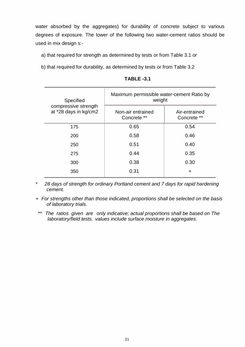
water absorbed by the aggregates) for durability of concrete subject to various
degrees of exposure. The lower of the following two water-cement ratios should be
used in mix design s:-
a) that required for strength as determined by tests or from Table 3.1 or
b) that required for durability, as determined by tests or from Table 3.2
TABLE -3.1
Specified compressive strength at *28 days in kg/cm2
Maximum permissible water-cement Ratio by weight
Non-air entrained Air-entrained Concrete ** Concrete **
175
200
250
275
300
350
0.65
0.58
0.51
0.44
0.38
0.31
0.54
0.46
0.40
0.35
0.30
+
* 28 days of strength for ordinary Portland cement and 7 days for rapid hardening cement.
+ For strengths other than those indicated, proportions shall be selected on the basis of laboratory trials.
** The ratios given are laboratory/field tests.
only indicative; actual proportions shall be based on The values include surface moisture in aggregates.

22
TABLE- 3.2
Allowable maximum net water-cement ratio for durability of concrete
Type or location of concrete or structure and degree of exposure A
Water-cement ratio by weight
B
a) All exposed concrete structures including 0.55 ±0.02 Aqueduct
b) Concrete in structures or parts of 0.58 ± 0.02 structures to be covered with back-fill or to
be continually submerged or otherwise protected from the weather such as cut off walls, foundations, parts of sub-structures.
c) Concrete that will be subject to attack by 0.50 ± 0.02 sulphates, alkalis in soil and ground waters.
d) Concrete deposited by tremie in water 0.45 ± 0.02
e) Canal lining 0.58 ± 0.02
NOTES:-
1. For concrete not exposed to weather, such as the interior of buildings and
portions of structures entirely below ground, no exposure hazard is involved and
the water content will be selected on the basis of strength and workability
requirement.
2. In working out water ratio, pozzolana, if any used, shall be assumed to be part of
cement.
3. In calculating the water-cement ratio, the amount of water shall be total weight of
water in mix, including all free water in the aggregate but not including any
moisture absorbed by then. The surface moisture shall be determined in
accordance with Designation 11 as U.S.B.R. “Concrete Manual” or IS: 2386 (Part-
III)-1963 reaffirmed 2016 “Methods of Tests for Aggregate for Concrete.” In at
absence of data the amount of surface water may be estimated from the values
given in Table 3.3.

23
TABLE-3.3
Surface water carried by average aggregate.
Aggregate
Approx. Quantity of surfaces water liters/cu
meter.
Very wet sand.
Moderate wet sand.
Moist sand.
* Moist gravel or crushed rock
120
80
40
20 to 40
*Coarser the aggregate, the less water it will carry.
3.4 Consistency
The proportion of aggregate to cement for any concrete shall be such as to
produce a mix which can work readily into the corners and angles of the forms and
around reinforcement bars with the method of placing employed on the work, but
without permitting the materials to aggregate or excess free water to collect on the
surface.
The amount of water used in the concrete shall be regulated as required to
secure concrete of the proper consistency and to adjust for any variations in the
moisture content or grading of the aggregates as they enter the mixer. Addition of
water to compensate for stiffening of the concrete before placing will not be permitted.
Uniformity in concrete consistency from batch to batch will be required. Each mixer
shall be equipped with a consistency meter that will provide a reliable continuous
indication of concrete consistency and record in on the combined autographic recorder
chart described in paragraph 2.1.2(c). The sensitivity of the consistency meters shall
be such that the effect of a change in slump of 12 mm shall be readily discernible to
the operator and the range of the meters shall be sufficient to include a slump of as
little as 25 mm. The design and construction of the consistency meters shall be such
as to eliminate appreciable errors in indicated consistency that would result from
friction in the mixer operation and variations in power input.

24
The slump, as a measure of concrete consistency shall be maintained fairly
uniform at the point of placement. When the mixer is at a considerable distance from
the form, slumps should be taken occasionally on the same batch at the point of
placement to determine the slump loss in handling. Compensation for excessive
slump loss, by allowing wetter consistency at the mixer with consequent higher water
and cement contents and increased aggregation in transit, should not be permitted.
The allowable slump loss in transit shall not exceed 25 mm.
The slump of the concrete after the it has been deposited but before it has been
consolidated, shall not exceed 50 mm for heavy mass concrete structures, the tops of
walls, piers, parapets and curbs, and for slabs that are horizontal or nearly horizontal;
100 mm for concrete in pumped or air-placed concrete, in side walls and; and 75 mm
for all other concrete. The Employer may require a lesser slump whenever concrete of
such lesser slump can be consolidated readily into place by means of the vibration
specified in paragraph 6.2. The use of buckets, chutes, hoppers or other equipment
which will not readily handle and place concrete of such lesser slump will not be
permitted.
The slump shall be measured in accordance with the method prescribed in
Designation 22 of the U.S.B.R. “Concrete Manual” and IS: 1199-1959 reffirmed
2018“Method of Sampling and Analysis of Concrete.”
3.5 Tests
3.5.1 Sampling Fresh Concrete
Samples from fresh concrete shall be taken as per IS: 1199-1959 reaffirmed
2018, and cubes shall be made, cured and tested at 28 days in accordance with IS:
516- part 4: 2018. Samples for strength tests of each class of concrete shall be taken
neither less than once a day nor less than once every 115 cubic meter of concrete or
for each 465 m2 of surface area placed. Sampling from chutes, conveyors and
transporting containers shall be avoided. Sample will be taken from concrete after it
has been placed and vibrated in the forms. Samples taken from air entrained concrete
shall be hand rodded in moulds to disturb the air content as little as possible. Samples
taken from the mixers or from chutes, conveyors, transporting containers, etc.,
whenever unavoidable, will be vibrated in the moulds to simulate the vibrations given
in the forms.

25
Separate portions of the samples shall be used for slump and unit weight tests
and for casting the cylinders/cubes. For slumps tests or compressive strength tests,
aggregate in concrete larger than 40 mm shall be removed by wet-screening or hand-
picking. However for air-entrained concrete the over-size aggregate shall be removed
by hand picking and not by wet screening. For larger cylinders/cubes, the maximum
size of aggregate left in the samples shall not be more than one-fourth the diameter of
the cylinder or cube dimension. The hand-picked concrete shall be remixed with a
shovel into a uniform mass before making slump tests or test specimens for
compressive strength. Occasional specimens as large as can be tested in the field
laboratory shall be cast without removing any aggregates. Such specimens shall be
tested to establish the relation between un-screened and normally screened samples.
The corrective factors thus determined shall be applied to the tests strength of
screened specimens in recording the average daily unit.
Slump tests and cylinder/cube specimens shall be made without delay after
sampling, as a delay of even 15 minutes may decrease the slump as much as 50%.
Samples for strength tests of each class of concrete shall be taken at least one from
each shift and in accordance with the following:
Quantity of
concrete in the work No. of samples
m3
1-5 1
6-15 2
16-30 3
31-50 4
>= 51 4 + one for each additional 50
m3 or part thereof.
3.5.2 Securing Hardened Specimens of Concrete from Structures
The procedure for securing, preparing and testing specimens of hardened
concrete from structures shall be in accordance with Designation 2 of the U.S.B.R.

26
“Concrete Manual” and Appendix „B‟ of IS: 457-1957, and IS: 1199-1959. The cores
from hardened concrete will be extracted from concern at such ages and locations as
directed by S.E./Director, Inspection & Control or his authorized agent. In general, the
concrete shall be 14 days old or older before the specimens are removed. Specimens
that show abnormal defects or that have been damaged in removal shall not be used.
A core specimen for the determination of compressive strength shall have a
diameter at least three times the maximum nominal size of the coarse aggregate used
in the concrete and in no case shall be final diameter of the specimen be less than
twice the maximum nominal size of the coarse aggregate. The length of the specimen,
when capped, shall be as nearly as practicable twice its diameter.
3.5.3 Testing
In general strength tests acceptance criteria inspection & testing on concrete
shall be in accordance with the provision of clause 15.1 to 17 of IS: 456-2000
reffirmed 2016.
The compressive strength of the concrete will be determined by testing 15 cm *
50 cm cylinder made and tested in accordance with Designation 29 to 33 of the
U.S.B.R. “Concrete Manual” or IS: 516-1959 “Methods of Tests for Strength of
Concrete” except that, for all concrete samples from which cylinders are to be cast,
the places of coarse aggregates larger than 40 mm will be removed by screening or
hand picking.
Compressive strength will also be determined by testing drilled cores, which will
be extracted from concrete at such ages and locations as may be directed by the
Employer. The cores shall normally be 15 cm or 25 cm in diameter except as
otherwise directed. The cores shall be painted with some legible identification mark.
The cores shall be prepared for testing by cutting the ends to form cylinders, whose
lengths are twice the diameter and by suitable capping, if required, and shall be tested
in the same manner as cast concrete cylinders. The cores shall be tested as soon as
practicable after extraction and shall be kept continuously moist either by wet burlap or
fog room curing until the time of test. The compressive specimens and cores drilled
from the structure shall be used for determining unit weight, specific gravity,
absorption tests and durability.

27
Slump tests will be made in accordance with Designation 22 of the U.S.B.R.
“Concrete Manual” or IS: 1199-1959 “Method of Sampling and Analysing of Concrete”.
3.6 Designation and Classification of Concrete Mixes
The mixes are designated in accordance with IS: 456-1964. The figure
appearing after word „M‟ indicates the strength of concrete mix in kg/cm2. The
maximum size of aggregates is indicated in mm after the dash (-) at the end, such as
“M 20-M-40”.
Specified Permissible stress in
Max. size of compression (kg/cm2 Grade of characteristic
Aggregates
)
Concrete compressive strength in mm
at 28 days in kg/cm2
Bending Direct
M 10 80
40 100 30 25
20
M 15 80
40 150 50 40
20
M 20 80
40 200 70 50
20
M 25 80
40 250 85 60
20
M 30 80
40 300 100 80
20
M 35 80
40 350 115 90
20
M 40 80
40 400 130 100
20
NOTE:-
i) The characteristic strength is defined as the strength of material below which not more than 5 percent of the test results are expected to fail.

28
ii) The characteristic compressive strength shall be measured on 15 cm cube at 28 days expressed in Kg/ cm 2.
iii) Designation of concrete lower than M 20 shall not be used in reinforcement
concrete.
iv) M 5 & M 7.5, of concrete may be used for simple foundations of a masonry walls. These mixes need not be designed.
v) Other properties of concrete shall be in accordance with IS: 456-2000.
vi) Instructions issued by the Employer for sampling and testing of concrete may
also be followed where necessary.
The minimum 28 days compressive strength shown in classifications table shall
be taken as the average of any five consecutive strength tests of the laboratory cured
specimens representing each class of concrete. Average strength tests shall have
values less than the specified strength.
3.7 Porous Concrete
Porous concrete may be placed as a slab under split sewer pipe drains of the
stilling basins and such other features. Porous concrete shall be composed of one part
of cement to 5.5 parts of the coarse aggregate, by weight. The aggregate shall pass
20 mm mesh and be retained on No.4 ASTM screen (IS sieve 4.75 mm). The amount
of water used in the concrete shall be such that the resulting cement paste will not fill
the voids of the aggregates but will thoroughly coat and bind the aggregate particles.
In placing porous concrete, care shall be taken that it is not over tamped or compacted
so as to reduce its porosity. The compressive strength of the porous concrete at 7
days, as determined by tests of 15 cm* 30cm cylinders made and tested in
accordance with the latest standard practice, shall be not be less than 70 kg/cm2. The
porosity of the concrete at 7 days shall be such that water will pass through a slab of
the concrete, 30 mm thick at the rate of not less than 407 liters per minute per sq.
meter of slab, with a constant 10 mm depth of water on the slab. The porous concrete
shall be placed to the grades and dimensions as directed.
3.7.1 PLUMS
The size of plums shall usually be 225 mm to 300 mm (each of 50 kg or more
such as one man can handle). Plums shall be sound and hard having crushing
strength not less than 350 Kg/cm2, and shall be perfectly free from earth or clay or

29
disintegrated matter or any adhering coating and properly washed. They shall not
have sharp corners or soft material embedded in them.
3.7.1.1 PLUM CEMENT CONCRETE
Cement Concrete shall conform to „Specifications for Cement Concrete‟ and
shall be of the specified normal mix. However, plum concrete shall not be used for the
concrete mixes of M-25 or of higher strength.
3.7.1.2 PLACING OF PLUM CONCRETE
During concreting, first 45 to 60 cm thick concrete of the specified nominal mix
shall be laid at the bottom. While the top layer of this concrete is still wet, plums shall
be laid so that they are slightly embedded in the wet concrete. Normally, these plums
will sink-in sufficiently under their own weight in all but dry mixes. If the mix is sloppy,
the placing of the plums should be delayed until the concrete has commenced to
stiffen to avoid undue sinking. Complete submergence shall be avoided and all plums
should be significantly visible before placing the next layer of concrete. The thickness
of the latter and successive layers shall be at least twice of the largest plum. The
plums shall be placed so that the clear distance between any two is not less than the
greatest width or thickness of either of plums. The clear distance between any plum
and the face of the work or reinforcement shall not be less than 15 cm. The plums
shall be carefully placed and not dropped so as to avoid injury to the forms or to the
partially set adjacent concrete. Cement Concrete shall then be inserted in the
interstices and well packed.
It must be ensured that all dripping surface water is removed from the plums
before being embedded in the concrete. If plums of stratified stone are used, they
shall be laid on their natural bed. Care must be taken to ensure that no air is trapped
underneath the stone and the concrete does not work-away from their underside.
4. TOLERANCES FOR CONCRETE CONSTRUCTION
4.1 General
Permissible surface irregularities for the various classes of concrete surface
finish are specified in section 7. These finishes are to be distinguished from tolerance
as described in this section. The intent of this section is to establish tolerances which
are consistent with the construction practice, as well as governed by the effect which

30
the permissible deviations will have upon the structural action or operational function
of the structure.
In case of structure where tolerances are not stated in these specifications,
permissible deviations will be interpreted in conformity with the provisions of this
section. The tolerances set forth herein may however, be diminished if such
tolerances impair the structural action or operational function of a structure.
All concrete structure shall be constructed to the exact lines, grades, and
dimensions. However, inadvertent deviations from the established lines, grades and
dimensions will be permitted to the extent set forth in this section.
If an approved drawing shows specific tolerances in regard to certain
dimensions, these tolerances shall be considered in addition to the tolerances
specified in this section. Concrete work that exceeds the specified tolerance limits
shall be remedied or removed and replaced.
Concrete forms shall be set and maintained sufficiently within the tolerance
limits so as to ensure completed work within the specific tolerance. However, the
forms for the curved sections or in conduits which are to receive an F4 finish shall be
constructed as specified in the relevant section.
4.2 Tolerances for Structures
Tolerances for RCC structures
Variations from the Plumb
Variation from Plumb
In 3 M. ….. 6 mm
a. In the lines and surfaces of In any storey of 6 meters max. 9 columns, piers, walls and in arises. mm
In 12 meters or more 18 mm.
b. For exposed corner columns In any bay or 6 meters max. 6mm control joints grooves, and other In 12 m. or more ...12 mm. conspicuous lines
4.2.1 Variations from the Level
Variations from the level or from the grades indicated on the approved drawings:

31
a. In floors, ceilings, beam soffits, and in arises measured before removal of supporting shores.
In 3 meters...6 mm
In any bay of 6 m. max. 9 mm In 12 meters or more ...18 mm.
b. For exposed lintels, sills, parapets, horizontal grooves, and other conspicuous lines
In any bay of 6 m. max.: 6 mm In 12 m or more : 12 mm
Variations of the linear building lines from
established position in plan and related
position of columns, walls and partitions
In any bay of 6m max 12 mm In 12 m or more .. 25 mm
Variations in the sizes and locations Of sleeves. Floor opening, wall opening
6 mm
Variations in cross-sectional dimensions Minus …. 6 mm of columns and bears and slabs and walls
plus.......12 mm.
4.2.2 Variation in Footings
a. Variations of dimensions in plan
Minus ........-12 mm , +50 mm
b. Misplacement or eccentricity
2 % of the footing width in the directions of misplacement but not more than 50 mm.
c. Reductions in thickness Minus...5 % of specified thickness.
4.3 Tolerance in intake structures etc.
Tolerance in intake structures, bridges and pier are given below:
4.3.1 Intakes Structure Columns
A. variations of dimension from established position Max........ 12mm including distance between opposite columns
B. variations from the plumb for total height of column Max.......... 12 mm
C. variations of dimensions between trash rack slot Minus........ None adjacent columns including tolerance for concrete Plus........ 12 mm

32
constructions & irregularities of finish.
4.3.2 All Other Structures
a. Variations of the constructed liner outline from established positions in plan
In 6 meters.... ± 12 mm and 12 meters..... ± 18 mm
b. Variations of dimensions to individual ...In24meters 36mm. In buried structural features from established position construction twice the above amount.
c. Variations from the plumbed from the In 3 meters.... ± 12 mm. specified better or from the curved surfaces of In 6 meters.... ± 18 mm. all Structures, including the lines and surfaces In 12 m. or more …..± 32 mm. of Columns, walls piers, buttress, arch In buried construction: twice the sections Vertical joint grooves & visible above mentioned. arises.
d. Variations from the level or from the grades In 3 meters.... ± 6 mm. indicated on the approved drawings in slabs, In 19 meters or more…….. ± 12 mm. beams soffits, horizontal joint grooves and In buried construction: twice the visible arises above mentioned.
e. Variations in cross-sectional dimensions of Minus................ 6 mm. columns beams buttresses, piers & similar Plus................. 12 mm. members
f. Variations in the thickness of slabs, walls, Minus................ 6 mm. arch sections and similar members Plus................. 12 mm.
4.3.3 Footings for Columns etc.
Tolerances for footings for columns, piers walls, buttresses and similar members:
a. Variations of dimensions in plan.
Minus...12 mm; Plus......50 mm
b. Misplacement of eccentricity.
2 % of footing width in the direction of misplacement but not more than...50mm
c. Reductions in thickness 5 % of specified thickness
4.3.4 Sills and Side Walls etc.
Tolerances for sills and side walls for gate and similar water-tight joints are given below:

33
a. Variations from the plumb and level. ≤ rate of 3 mm in 3 m. Max. 5 mm.
b. Variations from indicated spacing.
For effective depth 200 mm or less ± 10 mm.
For effective depth more than 200 mm ± 15 mm.
4.3.5 Bridges and Piers
a. Departure from established alignment.
25 mm
b. Departure from established grades. 25 mm
c. Variations from the plumb or the specified batter in the 12 mm, Max 18 lines and surfaces of piers in 3 meters mm
d. Variations from the level or from the grades indicated in 3 M.......12 mm. on the drawings in slabs, beams, horizontal grooves and Max 18 mm. railing offsets.
4.3.6 Variations in Steps
a. In a flight of stairs ........Rise ......3mm;Tread 6mm.
b. In consecutive steps
Rise.........2 mm; Tread......3 mm.
4.4 Lining of Approach etc.
Tolerance for lining of approach and canal, and lining of excavated slopes are given below:
a. Departure from established alignment.
25 mm
b. Departure from established grades and slopes 25 mm
c. Thickness of lining. Minus....5 % of specified thickness.
d. Variations from specified width of section at any 1/4th of 1% plus 12 mm. height
e. Variations from established height of lining 1/2th of 1% plus 25 mm.

34
f. Variations in surfaces. Invert....6 mm in 3 m.
Sides slopes..12 mm in 3 m.
4.5 Monolithic Aqueduct and Culverts
a. Departure from established alignment.
25 mm
b. Departure from established grades and 25 mm Slopes
c. Variations in thickness. At any point.....minus 2.5 % or 6 mm whichever is greater; next any point...... plus 5 % or 12 mm whichever is greater.
d. Variations from inside dimensions. 1/2 or 1 percent
e. Variations in surface. Inverts...6mm in 3 meters Sides slopes...12 mm in 3 m.
4.6 Anchors, Bends etc.
Tolerance for anchors, bends, manholes, turnouts, and similar structures:
a. Departure from established alignment.
25 mm
b. Departure from established grades. 25 mm
c. Variations from the plumb or the Exposed, in 3 meters... ....12 specified better in the lines and surfaces of mm. piers exposed Walls, and in arises. Backfilled in 3 meters ....25 mm
d. Variations from the level or from the Exposed in 3 meters ..... 12 mm grades indicated on the drawings in slabs, Backfilled in 3 meters ....25 mm beams, horizontal grooves and railing offsets.
4.7 Concrete Roads, Yards etc.
Tolerance for concrete roads, parking areas and repair and storage yards :
Departure from established, alignment

35
a. Concrete roads. ± 12 mm
b. Parking areas & Yards. ± 25 mm
Departure from established, longitudinal grade on any line
a. Concrete roads. ± 6 mm
b. Parking areas & Yards. ± 12 mm
Departure from established traverse template contour except at traverse joints
a. Concrete roads. ± 3 mm
b. Parking areas & Yards. ± 6 mm
Departure from established traverse template contour at traverse joints.
a. Concrete roads in width of one traffic lane ± 6 mm
b. Parking areas & Yards. ± 12 mm
4.8 Tolerance for Placing Reinforcement Steel
a) Variations of protective covering. With 50 mm cover.. 6 mm. With 75 mm cover..12 mm. With 150 mm cover 25mm
b) Variations from indicated spacing 25 mm provided total steel remains the same
c) for effective depth 200 mm or less 10 mm
d) for effective depth more than 200 mm 15 mm
The cover shall in no case be reduced by more than one third of specified cover
or five mm whichever is less.

36
5. FORMS FOR CONCRETE
5.1 General
Forms shall be used, wherever necessary to confine the concrete and shape it
to the required lines, or to ensure against contamination of the concrete by materials
caving or sloughing from adjacent surfaces left by excavations or other features of
work. All exposed concrete surfaces having slopes of 2 to 1 or steeper shall be
formed. Where the side slopes or walls or an excavations for a concrete structure can
be trimmed to the prescribed lines without sloughing, the use of the form will not be
required.
Forms shall be true to lines and grades within the allowable tolerances. Forms
shall have sufficient strength to withstand the pressure resulting from placement and
vibration of the concrete, and shall be maintained rigidly in position. Forms shall be
sufficiently tight to prevent loss of mortar from concrete. Chamfer strips shall be
placed in the corners of forms so as to reduce beveled edges on permanently
exposed concrete surfaces. Interior angles on such surfaces and edges at formed
joints will not require beveling unless requirement for beveling is specially laid down.
Where forms for continuous surfaces are placed in successive units, care shall be
taken to fit the forms over the completed surfaces so as to obtain accurate alignment
of surfaces and to prevent leakage of mortar. All forms shall be so constructed that
they can be removed without hammering or prying against the concrete.
Forms for side walls shall be provided with openings of ample size for
supervision, vibration and inspection. The openings shall be located in the crown and
along two longitudinal lines in each side wall. The openings along the two selected
longitudinal lines in each side wall shall be staggered and shall be spaced at not more
than 2.5 meters on centres along each longitudinal line. Opening in the crown shall be
spaced at not more than 2.5 meters on centers and shall be located alternatively on
each side of the Aqueduct center line.
Forms for concrete surfaces for which finish F3 is specified shall not be
constructed continuously from lift to lift but shall be removed after concrete in a lift has
hardened and reset for the next life. The reset forms shall overlap the hardened
concrete in the lift previously placed by not more than 25 mm and shall be tightened
snugly against the hardened concrete so that, when concrete placement is resumed,

37
the forms will not spread and allow offsets or loss of mortar at construction joints.
Additional bolts or form ties shall be used as necessary to hold reset forms tight
against the hardened concrete.
5.2 Forms Sheathing and Lining
Wood sheathing or lining shall be of such kind and quality or shall be so treated
or coated that there will be no chemical deterioration or discoloration of the formed
concrete surfaces. The type and condition of form sheathing and lining, and
fabrications of forms for finishes F2, F3 and F4 shall be such that the form surfaces
shall be even and uniform. The ability of the forms to withstand distortion caused by
placement and vibration of concrete and the workmanship used in form construction
shall be such that the formed surfaces will conform with the applicable requirements of
these specifications pertaining to finish of formed surfaces. Where F3 is specified, the
sheathing or lining shall be so placed that joints marks on concrete surfaces will be in
general alignment both horizontally and vertically.
Except where otherwise specifically provided, materials used for form sheathing
or lining shall conform to the following requirements:-
Required finish of Formed surface
or lining
Wooden sheathing
Steel sheathing
Steel lining
F1 Any grade Permitted Permitted
F2 Common shiplap or plywood sheathing Permitted Permitted or lining if approved
F3
Common T & G Except where
Plywood lining or sheeting as
specifically required
Not permitted
Not permitted.
F4
For plane surfaces Common T & G shiplap or plywood. For warped surfaces, timber which is free from knots and imperfections and which can be cut and bent accurately the required curvatures without splintering or splitting.
Permitted
Not permitted.

38
* Steel ‘Sheathing’ denotes steel sheets, not supported by a backing of wood boards. Steel ‘lining’ denotes thin steel sheets supported by a backing of wood boards.
* Preferably F4 -Finish is required in Aqueduct including U/s and D/s sloping portions
of Aqueduct to minimize the transition losses.
+ Tongue and grooved.
Lagging that is rough on the side against which concrete is to be placed shall
be used to form inside surfaces of the structures that are to be plastered or to be
covered with terracotta or terrazzo.
5.3 Plywood Form Lining
Plywood shall be used for lining forms for the interior surfaces of the power
plants etc. which are exposed permanently to view. The plywood shall be water-proof,
non-warping, non-wrinkling, concrete from plywood manufactured with special water
resistant glue. In so far as practicable, the plywood sheets shall be of uniform width
and length and shall have a uniform thickness of not less than 16 mm, or not less than
9 mm if backed with shiplap or other approved backing. Tempered water-proof
pressed board or similar approved material not less than 3 mm in thickness may be
used instead of plywood if backed with shiplap or other approved backing. The joints
between the plywood or pressed- board sheets shall be smooth and as nearly perfect
as practicable, and no patching of the plywood or pressed-board lining will be
permitted. Minor imperfections in the plywood or pressed-board lining shall be
corrected by the use of plastic wood secured firmly in place and sand-papered smooth
after it has hardened thoroughly. The use of sheets metal to correct imperfections in
such lining of forms will not be permitted.
5.4 Tongue-and Groove Sheathing
Tongue-and-groove sheathing shall be used for forming interior surfaces of the
Power Plants etc. which are above water or fill level. The tongue-and-groove
sheathing shall be 10 cm or 15 cm, common T & G, and shall be placed horizontally,
provided, that either all 10 cm or all 16 cm timber shall be used.
5.5 Uniformity of Forming Materials
Forms for concrete surfaces required to receive F2 and F3 finishes shall be
constructed so as to produce uniform and consistent texture and pattern on the face of
the concrete. Metal patches on forms for these surfaces will not be permitted. The

39
form sheathing or lining shall be placed so that all horizontal form marks are
continuous across the entire surfaces. If forms are constructed of plywood form lining
or of panels of common timber, the vertical form marks shall be continuous for the
entire height of the surface. If forms are constructed of common timber that are not
panelled, the sheathing shall be cut square and vertical joints in the sheathing shall be
staggered and shall be made only at studs. For these surfaces one type of form timber
for all F2 surfaces and one type of material for all F3 surfaces shall be used, the T & G
timber shall either be 15 cm or all 20 cm timber.
5.6 Forms for Warped Surfaces Designated for F4 Finish
Forms for the transitions in the Aqueduct and other warped surfaces shall be
constructed so as to conform accurately to the required curvatures of the sections.
Dimensions from the center lines of the concrete surfaces shall be given at several
sections throughout the length of the warped surface. Intermediate sections shall be
interpolated as necessary for the type of form construction being used and the forms
shall be constructed so that the curvature will be continuous between sections. Where
necessary to meet requirements for curvature, the form sheathing shall be built up of
laminated splines cut to make tight and smooth form surface.
The form shall be so constructed that the joint marks on the concrete surfaces
inside of principal water conduits shall, as far as possible, follow the line of water-flow.
After the forms have been constructed and erected, all surface imperfections shall be
corrected, all nails shall be hidden and any roughness and all angles on the surfaces
of the forms caused by matching the form materials shall be dressed to the required
curvatures.
5.7 Form Ties
Embedded metal rods used for holding forms shall remain embedded and
except where F1 finish is permitted shall terminate not less than two diameters or
twice the min. dimension of the tie clear of formed faces of concrete. Where F1 finish
is permitted, ties may be cut-off flush with the formed surfaces. The ties shall be
constructed so that removal of end fasteners can be accomplished without causing
appreciable spalling at faces of the concrete. Recesses resulting from removal of ends
of form ties shall be filled in accordance with the provisions for “Repairs of

40
Concrete”. Embedded wire ties for holding forms will be permitted in concrete walls for
which finish F1 is specified, except walls to be subjected to water pressure.
Embedded wire ties will not be permitted in concrete works for which other finishes are
specified. Wire ties shall be set-off flush with the surface of the concrete after the
forms are removed.
5.8 Cleaning and Oiling of Forms
At the time the concrete is placed in the forms, the surface of the forms shall be
free from incrustation of mortar, grout or other foreign material that would contaminate
the concrete or interfere with the fulfillment of the specification requirements relating to
the finish of formed surfaces. Before concrete is placed, the surfaces of the forms
except surfaces of rough timber meant for concrete surfaces which are to be
plastered, shall be oiled with a commercial form oil that will effectively prevent sticking
and will not stain the concrete surfaces. After oiling, surplus oil on the form surfaces
and any oil on the reinforced steel or other surfaces requiring bond with the concrete
shall be removed. For wooden forms form oil shall consist of straight, refined, pale,
paraffin mineral oil. For steel forms, form oil shall consist of refined mineral oil suitably
compounded with one or more ingredients which are appropriate for the purpose.
Special care shall be taken to oil thoroughly the form strips for narrow grooves at
windows, doors and elsewhere so as to prevent swelling of the forms and consequent
damage to the concrete prior to or during the removal of forms
5.9 Removal of Forms
To facilitates satisfactory progress with the specified curing and enable earliest
practicable repairs of surface imperfections, forms shall be removed as soon as the
concrete has hardened sufficiently to prevent damage by careful form removal. Forms
on upper sloping faces on concrete, such as on the water sides of warped transitions,
shall be removed as soon as the concrete has attained sufficient stiffness to prevent
sagging. Any needed repairs or treatment required on such sloping surfaces shall be
performed at once and be followed immediately by the specified curing.
To avoid excessive stresses in the concrete that might result from swelling of
the forms, wood forms for walls openings shall be loosened as soon as this can be
accomplished without damage to the concrete. Forms for the openings shall be
constructed so as to facilitate such loosening. Forms for tunnel lining shall not be

41
removed until the strength of the concrete is such that form removal will not result in
perceptible cracking, spalling, or breaking of edges or surfaces, or other damages to
the concrete. Forms shall be removed with care so as to avoid injury to the concrete
and any concrete so damaged shall be repaired in accordance with the provisions for
“Repairs of Concrete”.
In normal circumstances and where ordinary Portland cement is used, forms
may generally be removed after the expiry of the following periods:-
a) Walls, columns and vertical faces of 24 to 48 hrs. as may be
all structural members decided by the Employer
b) Slabs (props left under) 3 days
c) Beam soffits (props left under) 7 days d)
e)
Removal of props under slabs :
1) Spanning up to 4.5 m 7 days
2) Spanning over 4.5 m 14 days
Removal of props under beams and
arches:
1) Spanning up to 6 m 14 days
2) Spanning 6 – 8 m 21 days
28 days 3) Spanning over 8 m
6. PLACING OF CONCRETE
6.1 Preparations for Placing Concrete
6.1.1 General
No concrete shall be placed until all form work, installation of parts to be
embedded, and preparation of surfaces involved in the placing have been approved
by the officer the Employer. No concrete shall be placed in water except with written
permission of the Employer and the method of depositing the concrete shall be subject
to his approval. Concrete shall not be placed in running water and shall not be
subjected to the action of running water until after the concrete has hardened. All
surfaces of forms and embedded materials that have become encrusted with dried
mortar or grout from concrete previously placed shall be cleaned of all such mortar or
grout before the surrounding or adjacent concrete is placed.

42
6.1.2 Foundations Surfaces
Immediately before placing concrete, all surfaces of foundations upon or
against which the concrete is to be placed, shall be free from standing water, mud,
debris, organic deposits, and other foreign material which may prevent a tight bond
between the boulder bed and concrete. All surfaces of rock upon or against which the
concrete is to be placed shall, in addition to the foregoing requirements, be clean,
solid and free from oil, objectionable coatings, and loose, semi-detached, or unsound
fragments, and shall be sufficiently rough to assure satisfactory bond with the
concrete. The cleaning and roughening of the surfaces of rock/boulders shall be
performed by the use of high-velocity air-water jets, wet sand blasting, stiff brooms,
picks or other effective means satisfactory to the Employer. In the case of earth or
shale foundation, all soft or loose mud and surface debris shall be scrapped and
removed. The surfaces of absorptive foundations against which concrete is to be
placed shall be kept continuously wet for at least 24 hours immediately prior to placing
concrete so that moisture will not be drawn from the freshly placed concrete
6.1.3 Surfaces of Construction and Contraction Joints
Concrete surfaces upon or against which concrete is to be placed and to which
new concrete is to adhere, that have become so rigid that the new concrete cannot be
incorporated integrally with that previously placed, are defined as construction joints.
The surfaces of constructions joints shall be clean, rough and damp when
covered with fresh concrete or mortar. Cleaning shall consist of the removal of all
laitance, loose or defective concrete, coatings, sand, sealing compound if used, and
other foreign materials. Cleaning of the surfaces of construction joints shall be
accomplished by wet sand blasting, followed by thorough washing. The joints in mass
concrete, and where practicable in other concrete, shall be cleaned and washed
immediately before concrete in the next lift is placed. Where it is not practicable to
clean the joints after forms are set, the joints shall be wet sand-blasted and washed at
the last opportunity prior to setting the forms and the joints shall be washed thoroughly
with air water jets immediately prior to placement of the adjoining concrete. The
method to dispose off waste water used in curing and washing of concrete surfaces
shall be such that the waste water does not stain, discolour, or affect the exposed
surfaces of the structures. All embedded pipes, recesses or openings used for

43
disposing of waste water shall, after they have served their purpose, be filled
completely with concrete mixed in the proportions specified. All pools of water shall be
removed from the surfaces of construction joints before the new concrete is placed.
The surfaces of all contraction joints shall be cleaned thoroughly of accretions
of concrete or other foreign material by scrapping, chipping, or other satisfactory
means.
6.1.4 Placing Anchors in Concrete
Anchors bolts, structural shapes, plates and bearings required in connection
with the installation of gates, gate hoists, operating machinery, and other apparatus
shall be placed in concrete as found necessary. Wherever practicable, anchors shall
be installed before the concrete is place, and except as otherwise provided, drilling for
installation of anchors in concrete will not be permitted.
Where the installation of anchors prior to placing the concrete is not practicable,
satisfactory formed openings shall be provided and anchors shall be grouted into the
openings at some later time. Anchors bolts for machinery may be placed in approved
pipe sleeves to facilitate installation of machinery, and the sleeves shall be completely
filled with grout after the locations of the bolts are finally determined.
6.1.5 Chipping and Roughening of Concrete Surfaces
At places, as directed by the Employer, concrete surfaces upon or against
which additional concrete is to be placed shall be chipped and roughened to a depth
of not more than 25 mm of the surfaces.
The roughening shall be performed by chipping or other satisfactory methods
and in such a manner as not to loosen, crack, or shatter any part of the concrete
beyond the roughened surfaces. After being roughened, the surfaces of the concrete
shall be cleaned thoroughly of all loose fragments, dirt, lime, and other objectionable
materials and shall be sound and hard and in such condition as to assure good
mechanical bond between old and new concrete. All concrete which is not hard,
dense, and durable, shall be removed to the depth required to secure a satisfactory
surface.

44
6.2 Placing of Concrete
6.2.1 Transportation
The method and equipment used for transporting concrete and the time that
elapses during transportation shall be such as will not cause appreciable segregation
of coarse aggregates or slump loss in excess of 25 mm in concrete as it is delivered to
the work.
6.2.2 Placing
Concrete shall be placed only in the presence of a representative of the
Employer. After the surfaces have been cleaned and dampened as specified, all
approximately horizontal surfaces of work and unformed construction joints shall be
covered, wherever practicable, with a layer of mortar, not less than 12 mm and not
more than 20 mm thick. The mortar shall have the same proportions of water, air-
entraining agent, cement and sand as regular concrete mixture. The water-cement
ratio of the mortar in place shall not exceed that of concrete to be placed upon it, and
the consistency of the mortar shall be suitable for placing and working in the manner
here-in-after specified. The mortar shall be spread uniformly and shall be worked
thoroughly into all irregularities of the surface. Concrete shall be placed immediately
upon fresh mortar.
In formed work, structural concrete placements shall generally be started with
an over-sanded mix containing 20 mm maximum size aggregate, an extra 50 kg. sack
of cement per cubic meter and having 125 mm slump, placed several cm. deep on the
joint at the bottom of the form. Concrete placement shall commence immediately
thereafter.
Retempering of concrete shall not be permitted. Any concrete which has
become so stiff that proper placing without retempering cannot be assured shall be
wasted. Concrete shall be deposited in all cases as nearly as practicable directly in its
final position and shall not be caused to flow in a manner that the lateral movement
will permit or cause segregation of the coarse aggregate, mortar or water from the
concrete, caused by allowing the concrete to fall freely from too great a height or at
too great an angle from the vertical or to strike the forms or reinforcement steel, will
not be permitted and, where such separation would otherwise occur, suitable drop
chutes and baffles shall be provided to confine and control the falling concrete.

45
Methods and equipment employed in depositing concrete in forms shall be such as
will not result in clusters or groups of coarse aggregates particles being separated
from the concrete mass, but if clusters occur they shall be scattered before the
concrete is vibrated. A few scattered individual pieces of coarse aggregate that can be
restored into the mass by vibration will not be objectionable
6.2.3 Formed Concrete Placement
Except as intercepted by joints, all formed concrete, except concrete in tunnel
lining, shall be placed in continuous approximately horizontal layers. The depth of
layers for mass concrete to be placed in lifts of 150 cm or so and other concrete shall
be generally not exceed 50 cm. Lesser depths of layers will be placed where 50 cm
concrete layers cannot be placed in accordance with the requirements of these
Specifications.
To prevent feather edges, the construction joints at the tops of horizontal lifts
near sloping exposed concrete surfaces shall be inclined near the exposed surfaces
so that angle between such inclined surface and the exposed concrete surface will not
be less than 50o.
6.2.4 Unformed Concrete Placement
In placing unformed concrete on slopes so steep as to make internal vibration
of the concrete impracticable without forming, the concrete shall be placed ahead of
non-vibrated slip-form screed extending approximately 75 cm back from its leading
edge. Concrete ahead of the slip-form screed shall be consolidated by internal
vibrators so as to ensure complete filling under the slip form.
6.2.5 Mass Concrete
In placing mass concrete, the exposed area of fresh concrete shall be
maintained at the practical minimum, by first building up the concrete in successive
approximately horizontal layers up to the full width of the block and to full height of the
lift over a restricted area at the downstream end of the block and then continuing
upstream in similar progressive stage to the full area of the block. The slope formed by
the unconfined upstream edges of the successive layers of concrete shall be kept as
steep as practicable in order to keep its area minimum. Concrete along these edges
shall not be vibrated until adjacent concrete in the layer in placed, except that it

46
shall be vibrated immediately when weather conditions are such that the concrete will
harden to the extent that it is doubtful whether later vibration will fully consolidate and
integrate it with more recently placed adjacent concrete. Cluster of large aggregate
shall be scattered before new concrete is placed over them. Each deposit of concrete
shall be vibrated completely before another deposit of concrete is placed over it.
Mass concrete shall not be placed during rains sufficiently heavy or prolonged
to wash mortar from coarse aggregate on the forward slopes of the placement. Once
placement of mass concrete has commenced in a block, placement shall not be
interrupted by diverting the placing equipment to other places.
The concrete shall be deposited, as nearly as practicable in final position and
shall not be piled up in large masses at any point and then pushed, shovelled, or
vibrated into space for long distances. The full capacity of the bucket may be
deposited in one operation where this has no objectionable effect on the placing of the
concrete, but near forms, in and around embedded metal work, and elsewhere as
directed, the contents of the bucket shall be discharged in such quantities that
satisfactory placing will be secured.
Concrete buckets shall be capable of promptly discharging the low slump, mass
concrete mixes specified, and the dumping mechanism shall be designed to permit the
discharge of as little as 0.3 cubic meter portion of the lead in one place. Buckets shall
be suitable for attachment and drop chutes be used where required in confined
locations.
6.2.6 Placement of Monolithic Concrete
Where concrete is placed monolithically around openings having vertical
dimensions greater than 60 centimeters or where concrete in decks, floor slabs, top
slabs, beams, girders, or other similar parts of structures is placed monolithically with
supporting concrete, the following instructions shall be strictly observed.
1. Placing of concrete shall be delayed from 1 to 3 hours at the top of openings and
at the bottoms of bevels under decks, floor slabs, top slabs, beams, girders, or
other similar parts of structures when bevels are specified and at the bottom of
such structure members when bevels are not specified; but in no case shall the
placing be delayed so long that the vibrating unit will not readily penetrate of its

47
own weight the concrete placed before the delay. When consolidating concrete
placed after the delay, the vibrating unit shall penetrate and revibrate the concrete
placed before the delay.
2. The last 60 cm or more of concrete placed immediately before the delay shall be
placed with as low a slump as practicable and special care shall be exercised to
effect thorough consolidation of the concrete.
3. The surfaces of concrete where delays are made shall be clean and free from
loose and foreign material when concrete placing is started after the delay.
4. Concrete placed over openings and in decks, floors, beams, girders, and other
similar parts of structures shall be placed with as low a slump as practicable and
special care shall be exercised to effect thorough consolidation of the concrete..
6.2.7 Concrete Below Scroll Case
Concrete below scroll case shall be done by a series of 250 mm dia J-pipes.
250 mm dia M.S. J-pipes shall be manufactured in curvature and shape as per
direction of the Employer out of 20 gauge black sheets. J-pipes should be placed in
proper position and be held in position with the help of stays as directed by the
Employer. Precaution shall be taken to prevent displacements and choking of these
pipes during concreting around scroll case up to the time of concreting through these
pipes. The joints shall be welded as to conform to the applicable welding codes to the
satisfaction of the Employer.
6.2.8 Construction Joints
Constructions joints shall be approximately horizontal unless otherwise directed
by the chief engineer and shall be given the prescribed shape by the use of forms,
where required, or other means that will ensure suitable joining with subsequent work.
Unless otherwise directed, keyways will not be required at constructions joints.
Horizontal construction joints in mass concrete shall have a slope of approximately 15
mm from midway between sumps and from edges of the blocks to the sumps to
facilitate the removal of clean by waste. All construction joints intersecting with
concrete surfaces exposed to view shall be made straight and level or plumb.

48
6.2.9 Cold Joints
Cold joints shall be avoided where practicable. In the event of equipment break
down or for any other reasons, continuous placing is interrupted, the concrete shall be
thoroughly consolidated at such joints to a reasonably uniform and stable slope while
the concrete is plastic. If thorough consolidation at the sloping joints is not obtained
the Employer may require the use of bulk-headed construction joints. The concrete at
the surfaces of such cold joints shall be cleaned and damped as required for
construction joints before being covered with fresh mortar and concrete. The cleaning
of such joints shall consist of the removal of all loose and foreign material.
In mass concrete placement, delays may occur which result in cold joints within
a lift. When placement is resumed while the concrete is so green (and therefore,
capable of ready bonding) that it can readily be dug out with a hand pick, the usual
construction joint treatment will not be required if (1) the surfaces are kept moist, and
(2) the concrete placed against the surfaces is thoroughly and systematically vibrated
over the entire area adjacent to the older concrete. If the delay is short enough to
permit penetration of the vibrator into the lower layer during routine vibration of
successive layers, the vibrations will assure thorough consolidation. By eliminating
clean up and mortar coat, extra thorough vibration at such cold and semi-cold joints in
lieu of the usual mortar-joints treatment avoids interference with normal placing
operation and it saves cement.
6.2.10 Consolidation
Concrete shall be consolidated to the maximum practicable density, so that it is
free from pockets of coarse aggregate and entrapped air, and closes snugly against
all surfaces of forms and embedded materials. Consolidation of concrete in structures
and in tunnel lining inverts shall be by electric or pneumatic-drive, immersion-type
vibrators. Consolidations of concrete in the side walls and shall be by electric or
pneumatic-drive form vibrators, vibrators supplemented where practicable by
immersion-type vibrators. Vibrators having vibrating heads 10 cm or more in diameter
shall be operated at speeds of at least 6000 rpm when immersed in concrete.
Vibrators having vibrating heads less than 10 cm in diameter shall be operated at
speeds of at least 7000 rpm when immersed in concrete. Immersion-type vibrators
used in mass concrete shall be heavy duty, two-man vibrators capable of readily

49
consolidating mass concrete of the consistency specified. Form vibrators shall be
rigidly attached to the forms and shall be operate at speeds of at least 8000 rpm when
vibrating concrete.
In consolidation each layer of concrete, the vibrator shall be operated in a near
vertical position and the vibrating head shall be allowed to penetrate and revibrate the
concrete in the upper portion of underlying layers. In the areas where newly placed
concrete in each layer joins previously placed concrete, particularly in mass concrete,
more than usual vibration shall be performed, the vibrator penetrating deeply and at
close intervals into the upper portion of the previously placed layer along these
contacts. In all vibration of mass concrete, vibration shall continue until bubbles of
entrapped air have generally ceased to escape. Additional layers of concrete shall not
be superimposed on concrete previously placed until the previously placed concrete
has been vibrated thoroughly as specified. Care shall be exercised to avoid contact of
the vibrating head with surfaces of the forms.
Disturbances of the surface concrete at a construction joint during the early
stages of hardening shall be avoided. Necessary traffic on new concrete shall be on
timber walk-ways constructed so as to not cause injury to the concrete.
For formed concrete surface to be exposed to high velocities of water special
precautions shall be taken to prevent or to minimize surface pitting without resorting to
over manipulation of the concrete next to the forms. The use of mechanical vibrator
complying with IS: 2505-1992, IS 2506-1985, IS 2514-1963 and IS: 4656-1968 for
compacting concrete is recommended. Over vibration or vibration of very wet mixes is
harmful and should be avoided, under vibration is also harmful.
6.3 Placing Temperature
Concrete in all structures shall be placed at temperature between 10oC and
21oC. .
General Guidelines for various works:
1. Placement of concrete from April to September may be done normally
during the night hours only i.e. starting in the evening and ending by
morning.

50
2. To prevent shrinkage cracks, curing of freshly laid concrete may be
commenced promptly after placement and should remain uninterrupted
during the specified curing period.
3. During hot weather, the transit mixers shall be insulated and steel forms
shall be sprayed with direct river water.
6.4 Weather Conditions
Concrete operations shall be temporarily suspended during excessively hot or
rainy weather when conditions are such that the concrete cannot properly placed and
cured.
During hot weather no concrete shall be deposited when the temperature within
the forms is more than 50oC. Whenever necessary, exposed surfaces of fresh or
green concrete shall be shaded from the direct rays of the sun and protected against
premature setting or drying by being cured under continuous fine spray of water.
During continued rainy weather or heavy downpour, all freshly placed concrete
shall be covered and protected against surface wash. Special precautions shall be
taken to prevent the formation of lean seams or sand streaks. Mortar coats for
bonding construction joints shall not be placed or left exposed if the rain is tending to
increase the water-cement ratio of the mortar. Under no conditions shall concrete be
placed in a pool or a sheet of water. The top of all badly washed or streaked surfaces
shall be removed and washed before depositing the next course.
For other precautions / measures required to be taken for extreme weather
concreting reference may be made to Indian Standard Code of practice for extreme
weather concreting, IS:7861 (Part I) – 1975 “Recommended practice for hot weather
concreting” and IS:7861 (Part II) – 1981 “Recommended practice for cold weather
concreting.”
7. FINISHES AND FINISHING OF CONCRETE
7.1 General
Allowable deviations from plumb or level and from the alignment, profile grades
and dimensions, as specified in Section 4, are defined as “tolerances” and are to be
distinguished from irregularities in finish as described herein. The classes of finish
and the requirements for finishing of concrete surfaces shall be as specified in this

51
section or as directed. In the event that finishes are not definitely specified in this
section, the finish to be used shall be that specified for similar adjacent surfaces, as
determined by the Employer. Finishing of concrete surfaces shall be performed only
by skilled workmen and in the presence of a representative of the Employer.
Surface irregularities are classified as “abrupt” or “gradual”. Off-sets caused by
displaced or misplaced form sheathing or lining of form sections or by loose knots in
forms or otherwise defective form timber, will be considered as abrupt irregularities
and will be tested by direct measurements. All other irregularities will be considered as
gradual irregularities and will be tested by use of a template, consisting of a straight
edge or the equivalent thereof for curved surfaces. The length of the template will be
150 cm for testing of formed surfaces and 300 cm for testing of unformed surfaces.
All exposed surfaces, except where finish F1 is specified, shall be cleaned of
unsightly incrustations, oil drippings, rust stains and drainage from concrete work at
higher levels.
7.2 Finishes for Formed Surfaces
The classes of finish for formed concrete surfaces are designated by use of
symbols F1, F2, F3, F4 and F5. No sack-rubbing or sand-blasting will be done on
formed surfaces. Except as required for finishing of surfaces of spillways, stilling
basing etc., as set forth in definition of F4 given below, no grinding will be required on
formed surfaces, other than that necessary for repair of surface imperfections. Unless
otherwise specified, the classes of finish shall apply as follows:-
F1 - Finish F1 applies to formed surfaces upon or against which backfill or concrete is
to be placed or which will otherwise be permanently concealed. The surface
requires no treatment after form removal except removal and repair of defective
concrete and filling of holes left by the removal of fasteners from the ends of ties
rods, as required in section 8, and the specified curing. Correction of surfaces
irregularities will be required for depressions only, and only for those which, when
measured as described in para 7.1, exceed 25 mm. Form sheathing may be
anything that will not leak mortar where the concrete is vibrated. Forms may be
built with a minimum of refinement.

52
F2 - Finish F2 applied to all formed surfaces not permanently concealed by backfill or
concrete, except surfaces for which finish F3, F4 or F5 is specified. Surfaces for
which finish F2 is specified will need no filling of pits or sack rubbing and no
grinding other than that needed for repair of surfaces imperfections. surfaces
irregularities, measured as described in paragraph 7.1, shall not exceed 6 mm for
abrupt irregularities and 12 mm for gradual irregularities. Where “no surfaces
irregularities” is specified, no abrupt irregularities will be permitted and gradual
irregularities shall not exceed 12 mm for the length of the surfaces designated.
The following surfaces generally receive F2 finish:-
a) Inspection galleries.
F3 - Finish F3 applies to formed surfaces, the appearance of which is considered to
be of special importance, such as surfaces of structures prominently exposed to
public inspection. No general stoning or grinding will be required on surfaces for
which finish F3 is specified, although in some cases, conspicuous air-holes shall
be filled by sack rubbing. Surface irregularities (measured as described in
paragraph 7.1) shall not exceed 3 mm for abrupt irregularities and 6 mm for
gradual irregularities, except that abrupt irregularities will not be permitted at
construction joints.
a) Exterior surfaces of buildings.
b) Decorative features on bridges.
c) Surfaces of structure permanently exposed to view.
d) Surfaces of access portals.
F4 - Finish F4 applies to formed surfaces for which accurate alignment and evenness
of surfaces are of paramount importance from the standpoint of eliminating
destructive effects of water actions. Abrupt irregularities shall not exceed 6 mm
for irregularities parallel to the direction of flow, 3 mm for irregularities not parallel
to the direction of flow. Gradual irregularities shall not exceed 5mm. Also, when
flow velocities exceed 12 meters per second, abrupt irregularities which are not
parallel to the direction of flow and off-set into the flow should be completely
eliminated by grinding on a 1 to 20 ratio of height to length.

53
a) Streamlined surfaces of outlets, in-take structures, and transitions.
F5 - Finish F5 is required for forced concrete surfaces where plaster, stucco, or
wainscoting is to be applied. Since a coarse-textured surface is needed for bond,
the concrete should be cast against rough faced form boards. Form oil should not
be used. Steel lining or steel sheathing is not permitted.
7.3 Finishes for Unformed Surfaces
The classes of finish for unformed concrete surfaces are designated by the
symbols U1, U2, U3, U4 and U5. Interior surfaces shall be sloped for drainage where
directed. Surfaces which will be exposed to the weather and which would normally be
level, shall be sloped for drainage. Unless the use of other slopes or level surfaces is
directed, narrow surfaces, such as tops of walls and curbs, shall be sloped
approximately 10 mm per 30 cm of width: broader surfaces such as walks, roadways
platforms, and decks shall be sloped approximately 5 mm per 25 cm. Unless
otherwise specified, these classes of finish shall apply as follows:-
U1- Finish U1 (screeded finish) applies to unformed surfaces that will be covered by
backfill or by concrete; surfaces of bridges pavements; and surfaces of sub-floors
which will be covered by concrete floor topping. Finish U1 is also used as the first
stage of finishes U2 and U3. Finishing operations shall consist of sufficient
levelling and screeding to produce even uniform surfaces. Surfaces irregularities,
measured as described in para 7.1, shall not exceed 9 mm.
U2 - Finish U2 (floated finish) applies to unformed surfaces not permanently
concealed by backfill or concrete or for which finish U3 is not specified. Finish U2
is also used as the second stage of finish U3. Stair treads after floating shall be
roughened by brooming parallel to the long dimensions of the tread. The
concrete shall then be tooled round. Floating shall be performed by use of hand
or power-driven equipment. Floating shall be started as soon as screeded
surfaces has stiffened sufficiently, and shall be the minimum necessary to
produce a surfaces that is free from screed marks and is uniform in texture. If
finish U3 is to be applied, floating shall be continued until a small amount of
mortar without excess water is brought to the surfaces, so as to permit effective
trowelling. Surfaces irregularities measured as described in para 7.1, shall not

54
exceed 6 mm. Joints and edges of gutters, side walls and entrance slabs and
also other joints and edges shall be tooled when so directed.
Surfaces to receive U2 finish include:-
a) Surfaces of inverts of siphons, aqueducts, Flumes.
b) Floors of canal structures.
c) Bridge floors and bridge deck.
d) Floors of galleries, sumps, culverts, adits and chambers.
e) Tops of piers & walls, except tops of parapet walls prominently exposed
to view.
f) Surfaces of gutters, side walls, stairs, and outside entrance slabs.
g) Slabs that will be covered with built-up roofing or membrane water
proofing.
h) Surfaces of safety rack structures and transitions.
U3 - Finish U3 is a trowelled finish. When the floated surface has hardened
sufficiently to prevent excess of fine material from being drawn to the surface,
steel trowelling shall be started. Steel trowelling shall be performed with firm
pressure, such as will flatten the sundry texture of the floated surfaces and
produce a dense uniform surface, free from blemishes and trowel marks; except
that light steel trowelling will be permitted on surfaces of slabs to be covered with
built-up roofing or membrane water proofing, in which event light trowel marks
will not be considered objectionable; surface irregularities, measured as
described in para 7.1, shall not exceed 6 mm. All abrupt irregularities, offsets and
bulges shall be ground to a slope not steeper than 1 in 20, provided that any
abrupt irregularities not parallel to the flow such as those at transverse joints
shall be to a slope not steeper than 1 in 40.
Finish U3 applies to the following surfaces:-
a) Tops of parapet walls prominently exposed to view.
b) Interior stair treads and thresholds.

55
c) Floors of transitions upstream and downstream of gate shaft.
d) Floor of the outlets works downstream from the gate frames.
U4 - The finished surfaces should be equivalent in evenness, smoothness, and
freedom from rock pockets and surfaces voids, to that obtainable by effective use
of a long handled steel trowel. Light surface pitting and light trowel marks are not
objectionable. Where the surface produced by a lining machine meets the
specified requirements, no further finishing is necessary. If a few spots are left by
the lining machine, there is no objection to the immediate use of a little mortar to
reduce the labour of producing an acceptable finish. Surfaces to receive F4 finish
include:-
a) Canal and lateral linings.
U5 - Finish U5 includes various special finishes requiring certain finishing procedures
in each case. It is also used for architectural purposes.
7.4 Maximum Allowance of Irregularities
Max. allowance of irregularities in concrete surfaces as given in preceding
paragraphs of this section are tabulated below:-
Finish (formed surfaces) Finish (unformed surfaces)
Type of Irregularities
F1 F2 F3 F4 F5 U1 U2 U3 U4
mm mm mm mm mm mm mm mm mm
Depressions 25 -- -- -- -- -- -- -- --
Gradual -- 10 5 5 5 -- -- -- --
Abrupt -- 5 3 5* 5 -- -- -- --
All Surfaces -- -- -- 3** -- 9 5 5 --
Canal surfaces Bottom -- -- -- -- -- -- -- -- 5 slab
Canal surfaces Side -- -- -- -- -- -- -- -- 10 slopes
* Allowance of irregularities or off-set extending parallel to flow.
56
** Allowance of irregularities or off-set not extending parallel to flow.
1. Allowance in mm measured from 1525 mm template.
2. Allowance in mm measured from 3050 mm template.
7.5 Finishing recesses
All recesses in concrete, where required for lightening units, lightening panel
boards, miscellaneous power boards, and all other recesses for installing equipment
shall be thoroughly cleaned and washed, and given one brush coat of neat white
Portland cement prepared by thoroughly mixing sufficient white Portland cement with
water to produce a consistency equivalent to that of thick cream. The cement shall be
applied while the surface is still moist. After the cement has set and has become
reasonably dry, the recess shall be painted with two coats of white vinolite paint.
8. PROTECTION, CURING & REPAIR OF
CONCRETE 8.1 Protection of Concrete
All concrete shall be adequately protected from mechanical injury. Unhardened
concrete shall be protected from heavy rains and flowing water. No fire or excessive
heat shall be permitted near or in direct contact with concrete at any time. All galleries
and conduits etc. shall be bulk headed during construction period to prevent free
circulation of air and resultant drying of concrete. Exposed finished surfaces of all
concrete shall be protected from the direct rays of the sun for at least the first three
days after placement. Such protection shall be made effective as soon as practicable
after the placing of unformed concrete or after the removal of forms from formed
concrete.
8.2 Curing of Concrete
Concrete shall be cured either by water (water curing) or by the use of sealing
compounds (membrane curing).
8.2.1 Water Curing
Concrete cured with water shall be kept wet for at least 14 days for ordinary
Portland cement concrete and 21 days for low heat or pozzolana mixed cement
concrete after placement of concrete. Curing shall start as soon as the concrete has
hardened sufficiently to prevent damage by moistening the surface and shall continue
until completion of the specified curing period or until covered with fresh concrete. The
concrete shall be kept wet by covering the unformed surface with water-saturated

57
material (such as damp sand, or by use of wet sacks) or by a system of perforated
pipes, mechanical sprinkler, or porous hose, or by any other approved method which
shall keep all surfaces of concrete continuously wet. Appropriate measures shall be
adopted to protect exposed surfaces of fresh concrete from water spray.
All equipment needed for adequate protection and curing of the concrete shall
be on hand and ready to install before actual concrete placement begins. Detailed
plans, provisions and procedures whereby the various protection and curing phases
will be firmly established, and shall be settled prior to the initial stages of concreting
operations.
Water for curing shall be clean and free from any element which will cause
staining or discolouration of concrete besides meeting the specifications for water
used for mixing concrete.
Where forms of lagging are used and left in place during curing, the lagging
shall be kept wet at all times to prevent the lagging from opening at the joints. Forms
in tight contact with new concrete shall also be kept wet so as to keep the surface of
new concrete as cool as possible.
Construction joints shall be cured in the same manner as other concrete
surfaces & shall be kept moist for at least 72 hours prior to the placing of additional
concrete upon the joints.
8.2.2 Membrane Curing
Membrane curing shall be application of a sealing compound which forms a
water retaining membrane on the surface of the concrete. The sealing compound shall
be white- pigmented and shall conform to U.S.B.R. “Specifications for Sealing
Compound for Curing Concrete” June 1, 1961 or its equivalent. The compound shall
be of uniform consistency and quality within each container and from procurement to
procurement.
Sealing compound shall be applied to the concrete surfaces by spraying in one
coat to provide a continuous, uniform membrane over all areas. Coverage shall not
exceed 3.5 sq. meters per litre and on rough surfaces coverage shall be decreased as
necessary to obtain the required continuous membrane. Mortar encrustations and fins
on surfaces designated to receive finish F3 or F4 or F5 shall be removed prior to

58
application of sealing compound. The repair of all other surface imperfections shall not
be made until after application of sealing compound.
When sealing compound is used on unformed concrete, surface application of
the compound shall commence immediately after the finishing operations are
completed. When sealing compound is to be used on formed concrete surfaces, the
surfaces shall be moistened with a light spray of water immediately after the forms are
removed and shall be kept wet until the surfaces will not absorb more moisture. As
soon as the surface film of moisture disappears but while the surface still has a damp
appearance, the sealing compound shall be applied. Special care shall be taken to
ensure ample coverage with the compound at edges, corners and rough spots of
formed surfaces. After application of the sealing compound has been completed and
the coating is dry to tough, any required repair of concrete surfaces shall be
performed. Each repair, after being finished, shall be moistened and coated with
sealing compound in accordance with the foregoing requirements.
Equipment for applying sealing compound and the method of application shall
be in accordance with the provision of the U.S.B.R. “Concrete Manual” or its
equivalent and other operations shall be such as to avoid damage to coatings of
sealing compound for a period of not less than 28 days. Where it is impossible
because of construction operations to avoid traffic over surfaces coated with sealing
compound, the membrane shall be protected by covering of sand or earth not less
than 25 mm in thickness or by other effective means. The protective covering shall not
be placed until the sealing membrane is completely dry. Before final acceptance of the
work, all sand or earth covering shall be finally removed in an approved manner. Any
sealing membrane that is damaged or that peels from concrete surfaces within 28
days after application shall be repaired without delay and in an approved manner.
Sealing compound shall be tested before use after obtaining proper samples.
Sampling will be in accordance with Designation 38 of the U.S.B.R. “Concrete
Manual” or its equivalent.

59
8.3 Repair of Concrete
Repair of concrete shall be performed by skilled workmen and in the presence
of a representative of the Employer. All imperfections of concrete surfaces shall be
corrected as necessary to produce surfaces that conform to the requirements
specified in Section 7. Repair of imperfection in formed concrete shall be completed
within 24 hours after removal from surfaces for which finishes F2, F3, F4 and F5 are
specified and encrustations shall be removed from surfaces for which finishes U2, U3,
U4, U5 are required. Concrete that is damaged from any cause and concrete that is
honeycombed, fractured, or otherwise defective and concrete which, because of
excessive surface depression must be excavated and built up to bring the surface to
the prescribed lines, shall be removed and replaced with dry-pack mortar or concrete,
as here-in-after specified (see paragraph 8.4 for dry-pack and refer to U.S.B.R.
“Concrete Manual” for mortar filling and concrete filling procedures). If removal of the
ends of form ties results in recesses larger than 6 mm in diameter or in the minimum
dimension, the recesses shall be filled with dry-pack except that filling of recesses in
surfaces designated to receive finish F1 will be required only where the surfaces are
required to be coated with damp proofing, and where the recesses are deeper than 25
mm in walls less than 30 mm thick.
Where bulges and abrupt irregularities protrude outside the limits specified in
Section 7 on formed surfaces for which finishes F2, F3, F4 are required, the
protrusions shall be reduced by bush-hammering and grinding so that the surfaces are
within the specified limits. Off-sets and other abrupt irregularities, on surfaces for
which finish F4 or F5 is required which exceed the limits specified in Sections 7, shall
except for F4 or other surfaces requiring reduction or elimination of irregularities by
grinding be dressed smoothly to bevels having cross-sectional length not less than 6
times the amount of projection. After dressing, the irregularities shall not exceed the
limits specified in Section 7. Off-sets and other irregularities, on F4 or other surfaces
requiring reduction or elimination of irregularities by grinding, shall be reduced or
eliminated in accordance with the finishing requirements.
Dry pack filling (see paragraph 8.4) shall be used for filling holes having at
least one surfaces dimension little, if any, greater than the holes depth, for narrow
slots cut for repair of cracks, for grout and cooling pipe recesses and for tie rod

60
fastener recesses as specified. Filling of holes left by the removal of fasteners from
the ends of the tie rods in surfaces for which finish F1 is specified will not be required.
Dry pack shall not be used for filling behind reinforcement or for filling holes that
extend completely through concrete section.
Mortar filling, placed under impact by use of mortar gun, may be used for
repairing defects on surfaces designated to receive F1 and F2 finishes where the
defects are too wide for dry pack filling and too shallow for concrete filling and no
deeper than the far side of the reinforcement that is nearest the surface.
Concrete filling shall be used for holes extending entirely through concrete
section for holes in which no reinforcement is encountered and which are greater in
area than 930 sq. cm and deeper than 10 mm and for holes in reinforced concrete
which are greater in area than 465 sq. cm. and which extent beyond reinforcement
and for holes resulting from drilling of 25 cm diameter concrete test cores as provided
in Section 3.
All materials used in the repair of concrete shall conform to the requirement of
these specifications and repairs shall be in accordance with procedures of chapter VII
of the U.S.B.R. “Concrete Manual” or equivalent. All fillings shall be bonded tightly to
the surfaces of the holes and shall be sound and free from shrinkage cracks and
drummy areas after the fillings have been cured and have dried. All fillings in surfaces
for which finish F3 is specified shall contain sufficient white Portland cement to
produce the same colour as that of the adjoining concrete.
All patching shall be done with extreme care, so that patches will not be
noticeable from a distance of 25 meters. Colour cement as an ingredient of the
patching mortar may be used, if necessary, to produce patch of same colour as the
adjoining concrete.
8.4 Dry Pack Mortar
Repair operations shall be proceeded by a careful inspection to see that the
hole is thoroughly clean and slightly wet but with a small amount of free water on the
interior surface. The surface shall then be dusted lightly and slowly with cement by
means of a small dry brush until all surfaces have been covered and darkened by
absorption of the free water by the cement. There shall be no dry cement in the holes

61
when packing begins and such cement if present shall be removed. The holes shall
not be painted with neat cement grout.
Dry pack mortar shall consist of a mixture of 1 part of cement to 2.5 parts of
sands that will pass a No. 16 ASTM Screen (IS Sieve No. 120). White cement will be
used in sufficient quantity to produce uniform colour matching with that of the
surrounding concrete at points wherever desired by the Employer.
For packing cone-bolt holes, a leaner mixture of 1:3 or 1:3.5 will be used. Only
enough water shall be used to produce a mortar which when used, will stick together
on being moulded into a ball by a slight pressure of the hands and will not exude water
but shall leave the hands damp. The proper amount of mixing water and the proper
consistency are those which will produce a filling which is at a point of becoming
rubbery when the material is solidly packed.
Dry pack mortar shall be placed and packed in layers having a compacted
thickness of about 10 mm. The surface of each layer shall be scratched to facilitate
bonding with the next layer. One layer may follow another immediately unless
appreciable rubberiness develops, in which case work on the repair shall be delayed
by 30 to 40 minutes. Under no circumstances shall alternate layers of wet and dry
materials be used.
Each layers must be solidly compacted over its entire surface by use of hard-
wood stick and hammer. These sticks are usually 20 to 30 cm long and not over 25
mm in diameter and are used on the fresh mortar like a caulking tool. Much of the
tamping will be directed at a slight angle and towards the sides of the hole to assure
maximum compaction in these areas. The holes shall not be over filled and finishing
shall be completed at once by laying the flat side of a hardwood piece against the fill
and striking it several good blows. Steel finishing tools shall not be used and water
must not be used to facilitate finishing.
8.5 Expansive Concrete or Mortar
In place where tight fillings are required such as back filling of block outs and
repair works in spillway stilling basin, a special expansive concrete or mortar is used
instead of ordinary dry pack mortar or concrete described above. This concrete has an
admixture of a very small quantity of aluminium powder that largely reduces

62
separation of water (bleeding) which would cause “settlement shrinkages” and also
cause expansion of concrete or mortar, thus filling up the confined space fully.
The aluminium powder, which should be of the unpolished variety, shall be free
from impurities and it shall have a fineness such that 100% of this passes through IS
Sieve 75 micron. The powder shall be first be blended with 50 parts by weight of some
inert pulverized material such as calcined shale. The blend shall then be added to the
concrete by sprinkling over the batch. The amount of blend to be used shall be
determined by laboratory tests. Aluminium powder shall not be used until test with job
material and at job temperatures have shown that effective expansion can be obtained
can be obtained and even then only under strict control.
The blend shall be mixed thoroughly with cement and sand before water is
added, otherwise the aluminium powder will float on water. Batches shall be small
enough to allow placement of freshly prepared mortar, as the action of the aluminium
becomes very weak about 45 minutes after mixing. After all ingredients are added, the
batch shall be mixed for 3 minutes.
The cavity in which concrete is to be filled should be confined by suitable form
work on all sides to take proper advantages of this expansive concrete.
9. STEEL REINFORCEMENT
9.1 Scope
The specification covers the item of providing, fabricating and placing in
position reinforcement bars for RCC works, anchor rods etc., including cost of steel,
binding wire, cleaning, cutting, bending, tying, welding wherever directed, lapping,
providing necessary protective works to keep the working area dry, desilting etc.,
complete with all leads and lifts.
9.2 Applicable Publications
The steel for reinforcement bars and all methods and procedures for fabrication
and placing in position of reinforcement bars for RCC works shall conform to following
latest revisions of IS specifications or other Internationally recognized standard
specifications:
IS: 456 Code of practice for plain and reinforced concrete.

63
IS: 1786 High strength deformed steel bars and wires for concrete
reinforcement.
IS: 2502 Code of practice for bending and fixing of bars for concrete
reinforcement.
9.3 Materials
The reinforcement steel shall be high-yield strength deformed bars of grade Fe-
500/550 conforming to latest revision of IS: 1786. All reinforcement steel required for
the work shall be procured by the Contractor from reputed manufacturer like SAIL,
TISCO, RASHTRIYA ISPAT NIGAM LTD., JSPL in standard lengths. The binding
wire for tying the reinforcement bars in position shall be 1.25 mm dia soft annealed
steel wire having yield point strength not less than 350 MPA.
9.4 Fabrication
Reinforcement bars shall not be straightened or bent in a manner that will injure
or weaken the material. Bars shall be bent cold to the shape and dimensions as per
design or as directed, using a bar bender operated by hand or power to attain the
proper shape. The radius of any bend shall not be less than 4 times the diameter of
the bar. Heating of reinforcement bars to facilitate bending shall not be permitted. The
reinforcement bars available from rejected work shall not be used. After fabrication,
the bars of same size, diameter and shape shall be grouped separately and stored in
racks duly marking the identification details for early identification during placing.
9.5 Placing in Position
All fabricated reinforcement bars shall be cleaned of rust, scale, dirt, grease or
other objectionable substances before use. Before the reinforcement bars are fixed in
position, it shall be verified that these are of the specified diameter and are cut and
bent in accordance with design. These shall be accurately placed and secured in
position by means of built in concrete blocks, steel chairs, hangers, spacers or other
suitable devices at sufficiently close intervals so that they will not sag either between
supports or be displaced during the placing of the concrete or by any operation of the
work. Cement mortar cover blocks of requisite size shall be used to maintain cover at
all places. The spacers and cover blocks shall be secured to reinforcements so that
these shall not be displaced during tamping or vibrating. No timber pieces, stone chips
or any other soft materials, to be used as cover blocks, shall be permitted.

64
The reinforcement bars shall have concrete covers as specified. Special care
shall be exercised to prevent any disturbance of reinforcement bars in concrete that
has already been placed. The reinforcement bars after being placed in position shall
be maintained in clean condition until it is completely embedded in concrete. Steel
reinforcement bars shall be placed in the concrete as directed. Where the exact
positions, size and shapes of reinforcement bars are not shown, detailed bar-lists and
bending diagram will be prepared and furnished by the Employer. The longitudinal
bars shall be straight and fixed parallel to one another and to the side of the forms or
as directed.
The ties, links and stirrups connected to the bars shall be tightly drawn so that
the bars are properly braced. The ties, links and stirrups shall be in actual contact with
the bars around which they are placed and their position shall be exactly as specified
in the design or as directed. Bar splices shall be used as per design unless the
Employer therein approves modifications. Splicing at points of maximum stress shall
be avoided. Splicing of adjacent bars at one position in plan shall be avoided as far as
possible. All protruding bars from concrete to which bars are to be spliced later shall
be protected from rusting by a thin coat of neat cement grout. Accurate records shall
be kept at all times of the number, size, length and weight of bars placed in position
for different parts of the work. All joints shall be lap joints, lap being as directed. Where
lap joints are provided in the reinforcing bars they shall be staggered and in conformity
with the requirements laid down in the latest revision of IS: 456. In exceptional cases,
welding of reinforcement rods shall be done wherever required as directed by the
Employer. No extra payment will be made on this account.
Welding of joints may be allowed in place of lapping at the direction of the
Employer. The joints shall be butt-welded and shall be of the V-cut type. Welding shall
be done by the electric arc method. The ends of the bars shall be cleaned of all loose
scales; rust, grease or other foreign materials and all welding shall conform to the best
modern practice. The reinforcement placed in position shall be got approved by the
Employer before embedding the same in concrete.

65
2. Specifications for Items Other than RCC
10. FOUNDATION EXCAVATION
10.1 Scope
These specifications shall govern the general requirements for all excavation
work relating to the foundations work. In case of doubt in the interpretation of these
specifications, the Employer or any other officer deputed on his behalf shall exercise
his discretion.
10.2 Setting Out
Reference burjis on definite station and chain lines shall be established at a
safe distance away from the top cut limits and their levels determined accurately with
reference to permanent Bench Marks.
Concrete pillars should be fixed along the proposed top of cut of the pit to be
excavated with correct ground levels marked on them with reference to permanent
Bench Marks to control excavation. All levels shall be with reference to established
bench marks not subject to subsidence or interference.
10.3 Clearing
The pit and surrounding area as required for excavation operations shall be
cleared of all trees, bushes, rubbish and other objectionable matter. Similar clearance
shall be done in areas earmarked for storing selected excavated materials for reuse
on the project. The cleared material shall be suitably disposed off by removal from the
site so as not to interfere with construction operations and maintenance of works. In
the work of disposal, all necessary precautions shall be taken for the protection of
persons, works and private property. Non-cohesive or any other excavated material
proposed to be used in the backfill around Aqueduct*- or for any other purpose shall
stacked separately as directed by the Employer.
10.4 Stripping
Before excavation work is taken up, all loose material close to the area to be
excavated which is liable to fall or otherwise endanger workmen or works, shall be
stripped. The method used shall be such as not to shatter or render unsuitable or
unsafe any formation which is originally sound.

66
10.5 Access and Haulage Roads
Access and haulage roads shall be constructed as and when required to
facilitate economical excavation operations and disposal of excavated material and
keeping in view the safety of adjoining structures, slopes, men, material and
equipments etc. The alignment and layout of these will be subject to approval of the
Employer to ensure that these do not interfere with permanent excavation lines,
slopes or foundations of appurtenant works.
10.6 Excavation – Basic Requirements
Excavation shall be done according to the approved drawings or direction of the
Employer. Excavation of the pit shall be done to the level as shown in the approved
drawings except that a depth of 1 meter + above the foundation level shall be kept
unexcavated. Excavation to the final foundation level shall be done after the relevant
tests are completed and just before the foundation is required for laying grounding
mat, concrete, etc. so as to avoid any deterioration of the foundation.
The bottom 1 m layer above the foundation level shall be excavated carefully at
the time of preparation of subgrade or placement of concrete in the raft so as not to
over-excavate, disturb or loosen the natural sub-grade in any manner. Over
excavation shall be avoided. In unavoidable circumstances, any excess excavation
under concrete raft of Aqueduct shall be filled up satisfactorily with lean concrete or
compacted back fill with prior approval of the Employer.
All excavation shall be done to the slopes, lines and grades as indicated on the
approved drawings except where, during the progress of work, it is felt necessary to
modify the slopes and or provide benches to ensure stability of the slopes. Any
deviation from approved drawings shall be done in consultation with the Employer.
A careful watch for the stability of slopes shall be kept during construction stage
and suitable measures shall be taken immediately if any movement is noticed before
proceeding with further excavation.
Effective dewatering arrangements shall be made to ensure that no boiling take
place at the bottom of the pit and that no sloughing/cavities on the excavated slopes
occur. To prevent blow out of the bed of the pit at all levels suitable arrangement shall
be made to observe artesian pressure so that the same, if found to be excessive, is
67
reduced by pumping before proceeding further with excavation of the pit. The pumped
water shall be discharged at a sufficient distance from the pit so that it flows away and
does not find its way back to the pit.
The pit material considered suitable for backfill of the pit, filling reaches of the
Hydel Channel, and which may be required to be so used shall be excavated in a
manner so as not to mix it with other materials and stock piled separately at proper
sites as directed by the Employer.
Disintegrated or loose and weathered material resulting from exposure or due
to any other reason shall be removed. The final clean up shall be done to the
satisfaction of the officer designated as Inspector prior to the placement of concrete or
backfill.
10.7 Method of Excavation
Excavation shall be done by standard excavation equipments such as rippers,
power shavers, bulldozers and by such techniques as conform to the best current
practice for such works and as required to reduce to the minimum any excavation and
not to cause injury to the foundation beyond the specified lines of excavation.
10.8 Disposal of Excavated Material
Excavated materials suitable for being used in the backfill or for any other
purpose on the project shall be carefully stock piled at suitable places designated for
the purpose or carried direct to the sites where required. Other material shall be
disposed off at placed earmarked for the purpose of disposal and as directed by the
Employer.
10.9 Dewatering
Where the foundation excavation extends below the water table, dewatering
arrangement shall be made in advance of excavation. The dewatering shall be
accomplished in a manner that would prevent the loss of fines from the foundation,
maintain stability of excavated slopes etc. and ensure all construction operations
being performed in dry conditions. Suitable methods shall be used for dewatering as
approved by the Employer.

68
11. BACKFILL
11.1 Scope
These specifications shall govern the general requirements for compaction of
backfill around structures to be constructed. Backfilling constitutes procuring of
suitable materials, depositing in the defined and approved areas and compacting to
the required specified density as specified by the Employer.
11.2 Location of Backfill & Production of Fill Material
When sufficient and suitable materials for the backfill are not available from the
Aqueduct excavation, the material shall be procured from approved resources as per
para 2.4 of the Specifications.
All borrow areas shall be stripped of top soil, loam, vegetation and other
materials which are unsuitable for filling, and the same shall be disposed off
separately as approved by the Employer. The approved backfill material, if stockpiled,
shall be maintained free of vegetation.
11.3 Preparation of Foundation Surface and Placement
Before the backfill is placed, the areas shall be cleared of all rubbish such as
bushes, grass, pieces of wood, steel, slush and other objectionable material. The
material so removed shall be burnt or otherwise disposed off or removed to a safe
distance so that, it may not interfere or mix with the earthwork to be carried out.
Backfill shall not be placed on any part of the foundation surface unless that part has
been inspected and approved. No slopes against which the fill is placed shall be
steeper than 1:1. In case steeper slopes are encountered they should be either
flattened or the area close to the slope shall be compacted to the desired density by
hand operated or other suitable equipment.
The fill shall be free from lenses, pockets or layers of material differing
substantially, in texture or gradation unless specified in Drawings. The combined
dumping, spreading and compacting operations shall be such that the materials will be
blended sufficiently so as to avoid rock pockets and to secure the degree of
compaction as specified.
69
11.4 Gradation Requirements
Cohesionless reasonably well graded pervious sand gravel material shall be
placed in the backfill. „Reasonably well graded‟ means that there should be a
reasonably good distribution of all sizes of particles from the coarsest to the finest and
without a major deficiency of any size or group of sizes. The distribution of material
must be uniform and such that compacted back-fill is free from lenses, pockets,
streaks or other imperfections. The gradation curves of the material to be used as
back-fill, shall be got approved from the Employer before using it.
11.5 Compaction
The compaction shall be done in layers. The depth of layer after compaction
unless otherwise specified, should not be more than 300 mm maximum, when tractors
or surface vibrators are used or a depth equal to the penetration length of the internal
vibrators. The layer under compaction shall be thoroughly wetted during compaction.
Proper precautions shall be taken to avoid damage to power plant building and other
structures. To achieve this, hand-operated pneumatic tools shall be used in the vicinity
of the structure, where the depth of the layer after compaction shall not exceed 100
mm. Rock pockets shall not be permitted any-where. The zone under the service bay
and ducts shall be compacted to 85% relative density. The rest of the backfill shall be
compacted to 60% relative density.
The adequacy of compaction and moisture control of pervious soils shall be
controlled by field density tests in conjunction with the relative density tests as outlined
in relevant IS 2720-1968 code. As the adequacy of compaction is specified in terms of
density achieved, the Employer can seek sufficient number of tests. At the start of
work a number of tests are required to specify the compaction operations to produce
the desired results, after this has been established, the number of tests required are
only those necessary to ensure that the specifications requirements are met with.
Minimum one test for each 150 cubic meters (200 cubic yards) shall be done in this
zone. For the rest of the backfill portion, it is expected that the required relative density
would be achieved by spreading the material in layers of specified thickness, flooding
and normal movement of the dumping equipment. This may, however, be occasionally
checked by field density tests to see that the required density is achieved.

70
The top surface of backfill shall be finally finished as per lines and grades to be
specified by the officer designated as Inspector. The low spots shall be filled up and
dressed up to the specified lines and grades after the backfill has withstood one rainy
season.
11.6 Sub-Soil Water Level
While compacting, the sub-soil water level in the fill should be maintained at
least 300 mm lower than the bottom of the layer being compacted.
12. Water Proofing Seals and Joints
12.1 Contraction Joints
Concreting shall be done on one side of the joint first. The form is removed
from the joint face and then a coat of sealing compound conforming to IS: 1834-1984
“Specifications for hot applied sealing compounds for joints in concrete”, shall be
applied to prevent adhesion of concrete to be placed against the formed face. The
reinforcement is discontinued and bond not allowed to develop between the joints
faces thereby introducing structural discontinuity. Contraction joints may be provided
between each block of one unit. These joints shall be effectively water sealed so that
the rain water is not allowed to seep through them.
12.2 Expansion Joints
Expansion joint is made by placing fresh concrete after separating the old
surface by joint filler. In order to provide an expansion joint 25 mm space shall be left
between the concrete joint faces to permit expansion and allow room for joint filling
between seals.
Preformed Joint Filler
25 mm or less thick preformed joint filler shall be placed as directed.
Materials
1) Preformed joint filler conforming to IS:1838 (Pt I)1983 “Specification for preformed
fillers for expansion joints in concrete non-extending and Resilient type (Bitumen
impregnated fiber).”
2) Vinyl resin paint – vinyl resin paint shall be in accordance with clause 7.3 of IS:
4461-1998.

71
3) Joint compound shall conform to IS 1834-1961, “Specification for hot applied
sealing compound for joints in concrete.”
Field Coating
All surfaces of the preformed joint filler shall be coated with vinyl resin paint or
bitumen. The surface or the preformed joint filler to be coated shall be clean and dry
and shall be free from loose, hanging particles. Each coat of Vinyl-resin paint shall be
applied at the rate of 1 Litre for each 50 sq. meter area and allowed to dry thoroughly
before the following coat is applied or before the joint filler is placed against the
completed side of the expansion joint. After the coated joint filler has been cut to
shape, all out edges of the coated joint filler shall be given two coats of Vinyl – resin
paint or bitumen.
Installation
The preformed joint filler shall be cut to cover the entire surface of the concrete
at the joints around which preformed joint filler is required to be placed except where
directed, the exposed edges of the filler materials shall be placed at a prescribed
distance back from the finished surfaces of the concrete. Where placed against
vertical concrete surfaces, the joint filler shall be held securely in place against the
completed side of an expansion joint by nails pre-cast in the first placed concrete. All
joints in the filler material shall be so water tight as not to permit any mortar from the
concrete to seep through to the opposite concrete or metal surface.
12.3 Asphalt Seals
The asphalt seals 140 mm x 140 mm, where directed by the Employer, shall be
provided in the Power House. Expansion joints are made water tight by use of rubber
water stops and asphalt seals. The water-stops are installed, one on each side of
diamond shaped hole which filled with asphalt as on additional seal against possible
leaks in the water-stops.
All materials for asphalt seals including metal cover plates and frames for
recesses, 18 mm electrodes fastening bars, clamps and wire for supporting electrodes
and asphalt material shall conform to the applicable IS Codes. The electrodes shall be
secured rigidly at different points and all electrode connections shall be made tight and
leak proof. After each lift of concrete has been completed, the recesses for the
72
seals shall be filled with hot asphalt during construction to ensure dense filling.
Heating shall be accomplished electrically through electrodes which shall be left in
place and be used for reheating if leak develops at a later stage. After each seal has
been completed to the top, the seal shall be capped.
The bidder when directed, shall connect the electrodes in the seal to the power
and electric current shall be passed through the electrodes until all the asphalt in the
seal is liquefied completely. The bidder shall make arrangements to avoid any leakage
of current.
Rubber Water Stops
The rubber water stops shall be fabricated and cured in such a manner that any
cross-section will be dense, homogeneous and free from porosity and other
imperfections.
The following minor surface defects will be acceptable
- Lumps and depressions not exceeding 0.64 cm in longest lateral
dimensions and 0.16 cm deep with no limit to the frequency of occurrence
- Lumps and depressions between 0.64 and 1.27 cm in longest lateral
dimension and 0.24 cm deep as long as the frequency of occurrence does
not exceed six in a 15.0 m length, and there are at least 5 cm between any
two such defects.
- Marks resulting from the tubing operation or handling during manufacturer,
with no limit to width or frequency of occurrence, as long as the thickness of
material below the mark is not less than the minimum thickness.
- Coarse or grainy surface texture.
- Suck-back along flash lines of molded goods, if not more than 0.16 cm wide,
0.16 cm deep, and not more than 0.60 cm long.
Any defects which are not within the above limitations shall either be repaired
as approved by the Employer or be removed by cutting out such defects and splicing
the water stop at that point. All factory splices shall be molded splices. All molded
splices shall withstand being bent 1800 around a 5 cm diameter pin without any
separation at the splice.
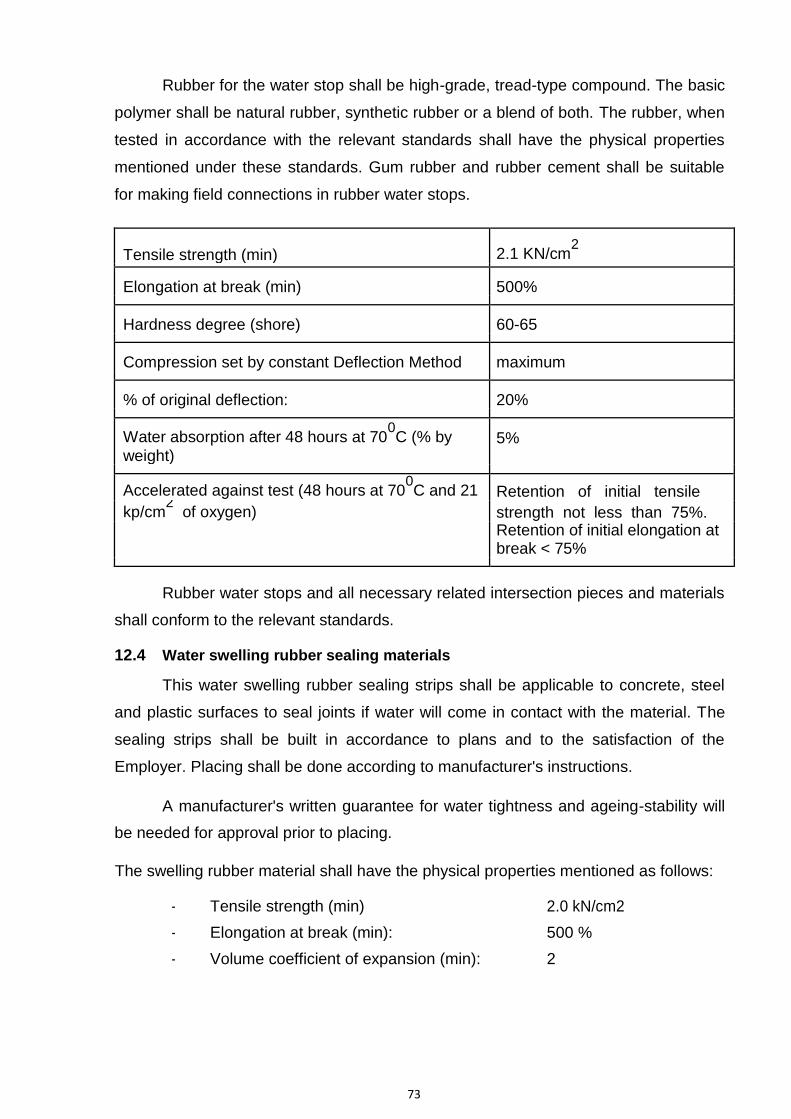
73
Rubber for the water stop shall be high-grade, tread-type compound. The basic
polymer shall be natural rubber, synthetic rubber or a blend of both. The rubber, when
tested in accordance with the relevant standards shall have the physical properties
mentioned under these standards. Gum rubber and rubber cement shall be suitable
for making field connections in rubber water stops.
Tensile strength (min) 2.1 KN/cm2
Elongation at break (min) 500%
Hardness degree (shore) 60-65
Compression set by constant Deflection Method maximum
% of original deflection: 20%
Water absorption after 48 hours at 700C (% by 5%
weight)
Accelerated against test (48 hours at 700C and 21 Retention of initial tensile
kp/cm2 of oxygen) strength not less than 75%.
Retention of initial elongation at break < 75%
Rubber water stops and all necessary related intersection pieces and materials
shall conform to the relevant standards.
12.4 Water swelling rubber sealing materials
This water swelling rubber sealing strips shall be applicable to concrete, steel
and plastic surfaces to seal joints if water will come in contact with the material. The
sealing strips shall be built in accordance to plans and to the satisfaction of the
Employer. Placing shall be done according to manufacturer's instructions.
A manufacturer's written guarantee for water tightness and ageing-stability will
be needed for approval prior to placing.
The swelling rubber material shall have the physical properties mentioned as follows:
- Tensile strength (min) 2.0 kN/cm2
- Elongation at break (min): 500 %
- Volume coefficient of expansion (min): 2

74
11.7
11.7.1
- Hardness degree (shore):
- Vulcanization:
Metal Seals
General
20-40
shall be possible
Details of type and placing of seals shall be as approved by Employer. The
seals shall be jointed carefully together by welding or brazing so as to form continuous
water-tight diaphragm in the joints. Adequate provisions shall be made to support and
protect the seals during progress of the work.
11.7.2 Materials
Materials for metal seals shall conform to the following specifications unless
otherwise approved in writing:
iii) Welding Rods – Welding rods shall be of a type and composition confirming to IS:
5898-1970 “Copper and Copper alloy welding rods and wires and magnesium
alloys welding Rods” IS 5856-1970 “Corrosion and heat resisting chromium-nickel
steel solid welding rods and bare electrodes”, for welding the copper or corrosion
resisting steel specified above.
12.5 P.V.C. Water Stops
12.5.1 General
PVC water stops of the types approved by the Employer shall be installed at
expansion, contraction & construction joints. PVC water stops are profiles, based on
specially formulated plasticized PVC compositions, available in different design such
as serrated (ribbed) as with central bulb.
12.5.2 Material
The PVC water stops shall be fabricated from virgin plastic compound the basic
resin of which shall be polyvinyl chloride manufactured by reputed concerns. The
compound shall contain any additional resin plasticizers, inhibitors, or other materials
such that, when the material is compounded it shall meet the performance
requirements given in these specifications. Reworked PVC of the same composition
generated from the manufacturer‟s water stops production may be used. Reclaimed
PVC shall not be used.

75
All water stops shall be extruded type and manufactured in such a manner that
the finished product shall be dense, homogenous and free from porosity and other
imperfections that might affect durability or performance.
12.5.3 Definitions
a) Reworked P.V.C: It is the material obtained from a finished product in the
fabrication of which only virgin P.V.C. was used. The material is intended for use
by the same manufacturer in the refabrication by the same process, of a similar
product. Reworked P.V.C. can be blended with only virgin P.V.C. of the same
composition and quality as the original material, the source of supply being the
same for both.
b) Reclaimed P.V.C. : It is a reused material that fails to meet the requirements of
reworked PVC as defined above.
12.5.4 Properties
The material shall have the following physical characteristics as recommended
by Central Water Commission:
No. Characteristics Unit Values
1 Tensile strength Kg/Cm2 116 minimum
2 Ultimate Elongation % 300 minimum
3 Tear resistance Kg/Cm2 49 minimum
4 Stiffness in flexure Kg/cm2 24.6 minimum
5 Accelerated extraction Tensile Kg/cm2 105 minimum
strength % 250 minimum
Ultimate elongation
6 Effect of Alkali 7 days
Weight increase % 0.25 maximum
Weight decrease % 0.10 maximum
Hardness change Point 5.0
7 Effect of Alkali 28 days

76
Weight increase % 0.4 maximum
Weight decrease % 0.3 maximum
Dimension change % 1.0 maximum
NOTE: - In respect of the tensile strength (under „1‟above) a higher value of about 140
Kg/cm2, with corresponding change in related values, shall be preferred.
12.5.7 Installation and jointing
a) Installation
The installation consists of embedding half the width of the water stop in
concrete, leaving the second half open. After concreting the first half, the second half
is also embedded leaving the central bulb free for expansion and contraction. It is
important that during placement of concrete, the water stop shall not be deformed due
to impact. The concrete shall be properly vibrated so that it develops intimate contact
with the water stop. Care shall be taken so as not to reduce effective cross section of
the water stop.
It is necessary that PVC water stops are placed near the centre of thin concrete
walls and about 150 mm away from the outside face of thick concrete walls.
Suitable precautions shall be taken to support and protect the water stops
during the progress of the work and any damaged water stops shall be repaired or
replaced. PVC water stop shall be protected from direct sunlight. The exposed parts of
these water stops which are partially protected in shall be protected by timber boxes
or other satisfactory means.
b) Jointing
During the installation, PVC water stops are often required to be jointed. There
are essentially two types of joints.
1) Straight joints
2) Mitred joints
Jointing shall be carried out as per instructions of the manufacturer. However,
the following method is suggested for general guidance.
77
1) Straight joint
i) Water stops are cut at the point of jointing by means of a cutting device such as
handsaw or sharp knife. The cut shall be smooth so as to result in close mating
of the surface.
ii) A heating plate with a wooden handle is heated to about 2000o C by blow lamp
or any other means. The heating plate shall not be overheated as it results in
charring of the PVC material.
iii) Two ends of the PVC water stops to be joined are pressed uniformly against hot
heating plate till the PVC material is fused. The heating plate is pulled back and
both ends are pressed together uniformly until the joint cools down to ambient
temperature. It is essential that the entire cross section of the water stops is
uniformly fused on heating. During the process the alignment of the complete
cross section especially the centre bulb shall be maintained.
2) Mitred Joints
Cross, L-shaped or T-shaped mitred joints can also be formed by fusion
method, described above for straight joints. This involves some experience to obtain
perfect joints. In case there is difficulty in attaining perfect joining, factory made
intersection pieces may be obtained from the manufacturer and their jointing with the
straight pieces carried out as described for straight joints.
Inspection of joints is necessary to ensure that all joints are properly made and
are water tight, and, that the water stop is properly located in the form. Placing of
concrete shall not be allowed to start until the location and condition of water stops
has been inspected and approved.
12.5.8 Inspection and Tests
a) General
Before placing order, the manufacturer shall be required to furnish latest test
certificate of all tests carried out on test specimen prepared from the same batch of
PVC compound as used in the manufacture of the PVC water stops for properties
specified under Clause 7.6.4 from reputed test house such as National test House,
Alipore, Calcutta. In addition, before acceptance of the materials, PVC water stops

78
shall be subjected to Laboratory tests for characteristics given under Clause 7.6.4.
Material for tests shall be furnished by the manufacturer and all tests shall be carried
out at their own works or if such facilities are not available then at approved test house
in the presence of S.E./ Director, Inspection & Control or his authorized agent.
General sampling procedure shall be as laid down in 7.6.6(b).
b) Sampling for Tests
Sampling for laboratory tests to determine physical properties of the compound
shall be taken at random to obtain the following number of test units from each
separate purchase order.
Size of purchase order No. of test unit
150 metres or less 1
151 to 300 metres 2
301 to 1500 metres 4
1501 to 3000 metres 8
3001 metres and above 15
Laboratory tests to determine physical properties of the PVC water stops,
required under these specifications, shall be performed on test specimen taken from
the finished product.
c) Tests : The test and the test procedures for the various properties of the material
given in clause 7.6.4 are described in Annexure-A.
11.7.3 Procurement and storing
PVC water stops shall be procured in rolls to facilitate handling. The inside
diameter of rolls shall not be less than 300 mm. Any roll of water stops, which is not to
be installed in the structure within 6 months after receipt of the material, shall be
loosened. All water stops shall be stored in as cool a place as practicable preferably at
27o C or less. Water stops shall not be stored in the open or where it will be exposed
to the direct rays of the sun.

79
11.7.4 P.V.C. Joint Strips
PVC joint strips, shall be used in the exterior face of the 25 mm expansion
joints as directed by the Employer.
For „Material & Fabrication and „Inspection & Tests‟ refer clause 7.6.2 and 7.6.6
respectively for PVC water stops.
11.8 Under drainage of Bye pass Channel and Special lining portion of hydel
Channel
Bye pass channel: Under drainage of bye pass channel shall be provided to
safe guard it against pressure exerted by sub soil water on it. The arrangement shall
consist of network of longitudinal drains and cross drains along with Pressure relieve
valves at suitable junction points of drains in the bypass channel in order to release
the uplift pressure on the bed of the various components of bye pass channel viz.
crest, glacis, cistern etc as per approved design. A minimum of 2 numbers of
longitudinal drains shall be provided along the length of bye pass channel and cross
drains should be provided at suitable intervals keeping in view of the presence of sub
soil water level however this distance shall not be more than 10 m in cistern portion of
the falls of bye pass channel or as approved by the Employer.
Special lining portion of hydel channel: A filter blanket shall be provided up to
depth of 3.7 to 4.3m below top of lining in this portion i.e. up to the minimum FSL in
channel. The filter blanket should be connected to longitudinal drains in the bed by
providing cross filter drains along the slope of the channel at 7.5m centre to centre.
Two longitudinal PVC/Asbestos Cement perforated pipe drains laid in trenches filled
with gravel and surrounded by graded filter layers along with cross drains at 45m
centre to centre shall be provided in special lining portion and that this network should
be in consonance and is connected to the hydel channel portion upstream or
downstream of special lining portion of hydel channel. Pressure relief valves should be
provided on longitudinal and cross drains in bed at 90 m centre to centre but should
staggered in adjacent rows.
The longitudinal and cross drains in bye pass and special lining portion of hydel
channel should be trapezoidal with bottom width as 500m and depth 525mm with side
as steep possible. The PVC/Asbestos Cement pipe should preferably of 150mm

80
diameter with 12mm diameter holes/perforation. On an average there should be a
minimum of 100 perforations/holes per meter length of pipe and these
perforation/holes shall be staggered in adjacent rows. The pipe should shrouded by
suitable filter. All pipes and fittings shall be maintained clean during the progress of
work and care should be taken that filter should not clog during construction. If any
pipe becomes either partially or wholly clogged, it shall be satisfactorily cleaned or
replaced. IS: 4558- 1995 shall be referred to for any other detail as required in field
during construction. The PVC pipes shall confirm to IS 4985-1988 and Asbestos
Cement pipe shall confirm to IS 9633-1980.
No work shall be covered over or surrounded by concrete until it has been
inspected and approved by the Employer. The entire work shall confirm to Punjab
PWD specifications or relevant IS coded or as directed by the Employer.

81
ANNEXURE-A
TESTS AND TEST PROCEDURE FOR PVC WATER STOPS
1. Tensile properties
Each test specimen shall be tested for tensile strength, ultimate elongation and
arithmetic mean result shall be calculated for each property. The calculated
results shall satisfy the requirements given in clause 7.6.4.Method of test shall
be in accordance with ASTM D-638 or equivalent. Test specimens shall be type
IV.
2. Tear Resistance
Each test specimen shall be tested and arithmetic mean result shall be
calculated. The calculated result shall satisfy the requirement given in clause
7.6.4.The method of test shall be in accordance with ASTM D-624 or
equivalent. Test specimen shall be cut by Die „B‟ as per above ASTM.
3. Effect of Alkali
Test specimens shall be prepared as per type IV of ASTM D-638 or equivalent
and the specimens shall be weighed singly to the nearest milligram.
The Alkali treatment will be as follows:-
The specimens shall be individually totally immersed in a solution consisting of
5.0 gm chemically pure sodium hydroxide and 5.0 gm chemically pure potassium hydroxide dissolved in one liter of distilled water. The solution shall
be maintained at 95 20 o C.
Effect after 7 days
After seven days, the specimens shall be removed rinsed, surface dried and
prepared for reweighing according to ASTM D-471 or equivalent except that the
acetone dip shall not be used. The Alkali treated specimen shall be weighed
singly to the nearest milligram and the arithmetic mean change in mass shall be
calculated in percent. The calculated result shall satisfy the requirements given
in clause 7.6.4.
Each Alkali treated test specimen shall be tested for hardness in accordance
with ASTM D-676 or equivalent using the Shore Durometer and the arithmetic
mean result shall be calculated. The calculated result shall satisfy the
requirement given in clause 7.6.4
Effect after 28 days

82
The dimension of the specimens shall be measured to the nearest 0.001 inch
and the specimens weighed to the nearest milligram and both observations
recorded.
The specimens shall then be subject to the effect of Alkali for 28 days, after
which they shall be removed, rinsed, surface dried and reweighed. The
arithmetic mean change in mass shall be calculated in percent. The calculated
result shall satisfy the requirement given in clause 7.6.4.
The Alkali treated test specimens shall also be measured to the nearest 0.001
inch and the arithmetic mean change in length shall be calculated in percent.
The calculated result shall satisfy the requirement given in clause 7.6.4.
4. Stiffness in flexure
A specimen 1” width and 2” in length shall be fixed in a vice, having jaws of the
smooth flat type, with one half of the length of the specimen free of jaws. The
vice shall be fixed to a suitable base and placed in universal testing machine.
The specimen shall be subjected to loading as a cantilever beam with the point
of loading at a position ¼” from the face of the vice jaws. A loading head of
greater width than the specimen and of suitable length shall be used to apply
the load. The loading head shall be of ½” material and shall be braced to
prevent any flexure under load. The loading face of the head shall be ground to
one side to form a knife edge and sufficiently founded to prevent gripping of the
specimen material by the head. The rate of loading shall be 0 2” per minute.
The stiffness in flexure shall be determined from the material load deflection
characteristics.
5. Accelerated extraction test
Each test specimen conforming to the shape and dimensions given in ASTM D- 412 or equivalent, using Die „C‟ as per ASTM shall be cut from the sample
submitted and weighed to the nearest milligrams. The specimens shall be
subjected to the same test as for „Effects of Alkali‟, continuously for not less
than 11 days after which, provided they have reached constant weight, they
shall be tested for tensile strength and ultimate elongation as per ASTM D-638
or equivalent. Under no circumstances, however, shall the specimen be tested
for tensile strength until they have reached constant weight. Constant weight is
assumed to have been obtained when the successive daily readings do not
differ from one another by more than 0.05% of the original weight.
Joints in the board shall be finished flush with fillers. Necessary cutouts for
electrical / AC fixtures shall be provided with a framing of wall channels.

83
3. Earthwork Specifications Canal
1.0 SCOPE
These specifications shall govern the general requirements and methods for
earth work, covering excavation and construction of embankments of Ravi Canal
and do not include the excavation relating to bridges and other works.
The excavations as herein defined include the disposal and transportation of
the excavated material to the adjoining filling reaches or as spoils, if necessary.
2.0 PLANNING
2.1 Prior to the commencement of a work, all relevant data shall be collected and
drawings prepared showing the location of the excavation, and embankment
reaches separately. On these drawings, both the excavation and filling reaches
should be distinctively indicated separately and the quantity of material to be
excavated and placed in fill stated in these reaches. This information would be
useful to ensure economic hauls throughout the work. Where the material to be
excavated consists of different types and if the various types have to be used
separately in the fill or run to spoil tip, the quantities of each class of material in
each area should be shown on drawings.
From the nature of material to be excavated and method of its disposal, the type
of excavation, the length of haul and the amount of compaction necessary, it is
possible to select the most suitable 0type of plant for a particular job.
2.2 No earthwork on canals should be started unless proper acquisition and
demarcation of land has been finalized and permission of concerned
organization obtained. Such land shall be demarcated by fixing permanent
boundary stones at intervals of 0.2 Km. on both sides on straight reaches and at
points where there is change in direction or change in land width. Similar
precautions shall be taken for defining the borrow areas also. Such areas will be
temporarily acquired and suitably demarcated.
3.0 SETTING OUT
3.1 Prior to the commencement of work, the centre line of the proposed channel
shall be marked by stones or pegs, each at about 30 metres. Curves shall be
laid out; top and bottom edges of the excavation and toe of all embankments
suitably peg marked. Reference pegs should also be driven into ground at a
fixed distance outside peg markings. All levels shall be referred to an established
bench mark not subject to subsidence or interference.

84
3.2 Profiles of designed canal section in fill and moderate cut reaches may be
marked at 25 m intervals in curves and 50 m in straight reaches.
4.0 CLEARING
4.1 The land over which embankments are to be formed and other excavation is to
be carried out, shall be cleared of all trees, stumps, roots, bushes, rubbish ant-
hills and other objectionable matter. The cleared material shall be suitably
disposed off.
4.2 All waste materials to be burned shall be piled neatly and when in suitable
condition shall be burned completely. Piling for burning shall be done in such a
manner and in such a location as to cause least fire risk. All burning shall be so
thorough that the materials are reduced to ashes. Necessary precautions shall
be taken to prevent fire from spreading to areas beyond the limits of cleared
areas. Suitable equipment shall be supplied for use in preventing and
suppressing fires and shall be kept available at all times.
4.3 In filling reaches, all holes and hollows whether originally existing or produced
by digging up stumps and roots, shall be filled with suitable earth, well rammed
and levelled off.
4.3.1 In filling reaches, the boulders in the top strata shall be removed and filled
with suitable material.
4.3.2 Boulders which may interfere in the work should be generally removed
after breaking them down, if necessary.
4.3.3 It is desirable to protect the trees outside the outer edge of the canal
embankments. However, the presence of trees in the vicinity of the canal can
accentuate variation of moisture content in the sub – stratum. In the case of
expensive spoils such excessive moisture variation can result in damage to the
lining. Such influence is believed to extend to distances equal to twice the height
of the tree.
5.0 STRIPPING LOOSE MATERIAL
5.1 Before excavation work is taken up, all loose material close to the area to be
excavated which is liable to fall or otherwise endanger the workmen or works
shall be stripped. The method used shall be such as not to shatter or render
unsuitable or unsafe any formation which is originally sound.
6.0 EXCAVATION
6.1 GENERAL

85
6.1.1The excavation for the Link canal in cutting reaches shall be done according
to the drawings issued by the Hydel Designs Directorate, Chandigarh.
6.2 EXCAVATION – BASIC REQUIREMENTS
6.2.1 The excavation in the canal section, where lining is to be provided, shall not be
done to the final grade as shown in the drawings in the first instance. To begin
with adequate margin to be decided by the officer designated as a Inspector
shall be left to provide for settlement and ravelling travel and for sub surface
preparation for the lining, provided that a minimum of 150mm excavation to the
final designed grades on bed and sides is the left to be done immediately before
the lining is laid. The aforesaid 150mm of the material shall be excavated
carefully at the time of preparation of the sub grade for the laying of lining.
6.2.2 The excavation slopes as shown on the drawings must be adhered to.
6.2.3 Canal section shall be excavated as shown on the drawings or as directed by
the engineer- in- charge. Both edges of the bank, especially the inner one shall be
neatly aligned symmetrically to the centre line of the channel. They shall be
absolutely straight in straight reaches and smoothly curved on bends. All gangways,
roads and stoppings shall be such that they fall within the canal section so that final
dressing of slope will consist of digging only and no filling will be required.
6.2.4 Suitable arrangements for drainage shall be provided to take surface water
clear of the excavation during the progress of work. Sumps may be constructed
at suitable places and water collected may be pumped out. When cutting on
sloping ground, it is advisable to cut a catch water drain on the higher side to
prevent water from flowing down the cutting slope.
6.2.5 Whenever ground water is met during excavation adequate measures shall be
taken to dewater the cutting. The choice of method to be employed and type of
equipment to be used would depend on the nature of ground and the volume of
the water to be dealt with.
6.2.6 If there is a continuous flow of water a sub drain with sumps at the intervals
may be installed. Drainage will be helped by excavating from downstream side
to upstream side so that water tends to drain away from the working face.
Generally area is drained by providing pilot cut to natural valley so as to drain
the sub soil water.
6.2.7 In case of lined canals sub soil water shall not be allowed to accumulate in the
bottom of the canal and pumping arrangements shall be so organized as to deal
with any temporary flood water which may occur. As described above (6.2.4,
6.2.5 and 6.2.6) the subsoil water should be

86
drained by providing drain or pumping the sub soil water so as to keep the area
dry as far as possible.
6.2.8 Excavation may be carried out by manual labour or by excavating machines.
The choice of type of excavating machine to be used will depend on the nature
and quantity of material to be excavated and also on the leads and lifts involved.
6.2.9 Exploratory holes and type of soil shall be determined before excavation. The
permeability characteristics of the soil encountered should be accessed by
making use of in place permeability tests as required. Canal sub grade soil on
the slopes and bottom with respect to probable future seepage and erosion
should be examined.
6.2.10 Above the lining, the rock may be allowed to stand at its steepest safe
angle and no finishing is required other then removal of rock masses which are
loose and are liable to fall.
6.2.11 Lined sections in the areas of high ground water shall be protected against
uplift by drainage system as per IS 4558- 1995- “Code of practice for under
drainage of lined canals” (Second revision). If fine grain soils (sand) are to be
placed as sub grade below concrete or membrane lining, this should be without
organic matter, gravel, pebbles etc. Natural sub grade should be inspected and
organic material, gravels, pebbles, protruding should be removed from sub grade.
Filter blankets should be provided beneath lining as per IS 4558-1995 to release
uplift pressure. All washable materials and any soil which generally becomes
unstable on saturation such as organic soil, loose , silts, expansive clays are
generally removed or properly treated for embankment and canal lining so as to
provide safe and stable sub grade under operating condition.
6.3 METHOD OF EXCAVATION
6.3.1 Excavation shall be done by standard excavation equipment such as rippers,
power shovels or bull-dozers and by such techniques as conform to the best
current practice for such works, as are required to reduce the over excavation, if
any, to the minimum.
6.4 ROCK EXCAVATION
6.4.1 Rock may be excavated by the following methods:-
a) Quarrying out by hand with suitable rock wedges and hammer steel bars, picks
etc. and breaking with rock hammers.
b) Loosening by use of pneumatic paving breakers.

87
c) Drilling suitable holes by hand with hand jumpers or pneumatic drilling
machines and breaking up rock with plugs and features.
d) Drilling holes by hand jumpers or pneumatic drilling machines as above, but
breaking the rock with suitable commercial explosives or blasting devices.
e) Ripping with suitable heavy duty tractors where the rock formation falls within
the range of repability of commercially available units.
6.4.2 Excavation of rock is usually done by loosening and removing the rock by
forming a slightly sloping open face across the cut and working towards this
open face. The depth and width of this face will vary according to the nature of
rock and method adopted. Several faces may be worked simultaneously, one
behind the other, with benches between each face; the space between the faces
and length of each method adopted for removing the rock. Provided that proper
equipment and technique are adopted, drilling and blasting is the most speedy
and economical method for excavating hard rock. For soft rocks ripping may
loosen the rock at greater speed and at much less cost.
6.4.3 Blasting shall be restored to only when absolutely necessary and shall be kept
to the minimum. Blasting where permitted by the officer designated as Inspector,
shall be carefully controlled to minimize the over breaks and preserve the
formation in the soundest possible condition beyond the minimum lines of
excavation wherever it becomes apparent that further blasting may loosen or
otherwise damage the slopes, the use of explosives shall be discontinued and
excavation completed by methods other than blasting.
6.4.4 Final cutting for 45 – 60 cm in hard rock shall be carried out by controlled
blasting or trimming or with the help of pneumatic paving breakers.
6.5 DISPOSAL OF EXCAVATED MATERIAL
Excavated material suitable for use in the filling reaches of the hydel channel shall be
used directly in the appropriate reaches to avoid rehandling. Material which are
not considered suitable for fill by the officer designated as Inspector shall be
systematically placed on the spoil banks in a manner indicated on the respective
drawings or as directed at site by the officer designated as Inspector.
6.6 PREPARATION OF SUB GRADE:
6.6.1 The excavation and Preparation of sub grade shall be done in accordance with
IS: 3873 – 1993 “ Code of Practice for lining in - in situ cement concrete lining on
canals. Where the original ground surface is below the grade of the canal the
bottom of the canal shall be filled to the grade in a manner prescribed for the
construction of canal embankments. In so far as

88
practicable the finishing operation required on canal sections shall be performed
simultaneously with canal excavation.
6.6.2 The sub grade and embankment for a canal may comprise of rock or soil.
Canal sections excavated in rock should be inspected to examine whether joints
or fissures exists which will cause excessive seepage or piping. In case this is
so, rock will require grouting of the section before lining. Rock surfaces on which
compacted earth is to be placed should be moistened before placing the first
layer of earth but standing water should not be allowed. The minimum soil cover
over rock should be 225 mm.
7.0 FILLING REACHES
7.1 DEFINITION OF CANAL SECTION
For the purpose of these specifications, the term canal section shall be defined
as all zones, special fill and parts thereof, above the foundation surface and
within lines and grades as shown on the drawings or as otherwise directed by
the officer designated as Inspector as the limits of the canal section.
7.2 DEFINITION OF MATERIALS
7.2.1 The section for filling reaches of link canal will be shown on approved
drawings. The sections may be classified as under:-
I) Normal filling reaches
II) Special reaches
I) Normal Filling Reaches
The filling part of these reaches will be divided into following fill zones:-
Impervious Fill zone No.1
Suitable earth material as per limiting grading curves shown in plate-4, spread in
150 mm layers compacted to 98% of the maximum dry bulk density or higher at
moisture content varying from optimum moisture content (O.M.C.) to 2% drier of
O.M.C.
Filter Fill zone No. 2
Selected free draining clean sand and gravels as per grading curves. The filter
material shall be placed in position in wet condition and compacted in 250 mm
layers. The minimum relative density of the compacted material shall not be less
than 70 percent.
89
Zone No. 3 Toe Drain – Gravel and cobbles as per limiting grading curves.
Pervious fill zone No. 4
The rest of the compacted zone shall consist of pervious fill material consisting
maximum size not more than 150 mm and not containing more than 5% fines
passing No. 200 sieve generally. It should be spread in 250 mm layers and
compacted to achieve minimum 70 percent relative density.
II) Special Reaches
These reaches shall cover portions adjoining to drainage works and other parts of
the canal where normal methods of placement and compaction are difficult to
work. Special specifications shall be issued on receipt of specific references of
such problematic reaches from the field.
7.3 GRADATION REQUIREMENTS
Limiting grading curves of material for different zones of the canal embankment are
shown in plate – 4.
7.4 SOURCES OF FILL MATERIALS
Zone No. 1 - Material for this zone shall be obtained from borrow areas approved by
the Board of Consultants (BOC) for the Shahpurkandi Dam Project and
conforming to the specified grading limits.
Zone No. 2 - Material for this zone shall be obtained from suitable borrow areas viz.
bed of khads; screening or processing if necessary shall be done to obtain
suitable material conforming to the specified grading limits.
Zone No. 3 - Material for this zone shall also be obtained from bed of khads;
suitable borrow areas or suitable rejects from a screening plant.
Pervious fill zone No. 4
Economics permitting, the material for this zone shall be obtained from the
cutting reaches of the Hydel Channel and any deficiency thereof shall be
supplemented from borrow areas duly approved by the officer designated as
Inspector. It shall conform to the specified grading limits in plate-4.
7.5 PRODUCTION OF FILL MATERIAL
7.5.1 Investigations:- Materials from the cutting reaches and borrow areas (where
necessary) shall be completely investigated and the engineering and index
properties of the material to be used in the canal filling sections shall be
established well in advance of construction. Distribution charts shall be

90
prepared indicating the reaches from where the material will be available and the
reaches where the material shall be utilized.
7.5.2 CLEARING AND STRIPPING
All borrow areas and the area of cutting reaches shall be stripped of top soil, sod,
loam, vegetation and other material which is unsuitable for filling, and the same
shall be disposed off separately at the places to be designated by the officer
designated as Inspector.
In case the excavation from cutting reaches are stockpiled for subsequent use, the
top surfaces of these stockpiles shall be maintained free of vegetation.
7.5.3 EXCAVATION OF MATERIAL
The material from cutting reaches and other approved borrow areas shall be
excavated by a power shovel or a scraper or any other suitable means as
directed. The material shall be excavated in a way that it forms a homogeneous
mixture for the particular zone.
7.6 FILL PLACEMENT
7.6.1 SCOPE
This section shall cover all work of placing material necessary for the construction of
canal sections to the lines and grades shown on the drawings. All operations of
construction viz. spreading, moisture conditions, compaction etc. of materials
shall be carried out in accordance with the requirement of this section or those
specified from time to time.
7.6.2 GENERAL
Before commencing the work, the toe of the slope on each side of the banks
shall be lock – spitted (Dag – Belled) and marked by pegs, firmly driven into the ground
at intervals of about 20 m. Profiles made by bamboos, earth or other convenient
materials and strings shall be set up for the guidance of the workmen at about 50 m
apart over straight reaches and about 25 m apart at curves. In setting up the profile for
an embankment a suitable allowance shall be made for settlement.
Masonry blocks shall be constructed at each profile to indicate the centre line
as also the bed level of the canal before starting the entire earthwork.
Embankments shall be built to the height and slope as shown on the drawings.
All the edges of the embankment shall be neatly aligned symmetrical to the centre line
of the channel. They shall be absolutely straight in reaches and smoothly curved at
bends.

91
The top of each embankment shall be levelled and finished so as to be
suitable for roadway and given a cross outward slope to drain away rain waters. The
bank carrying inspection road shall be given a suitable cross slope.
For embankment in which controlled compaction has not to be carried out,
suitable allowance be made for settlement.
An allowance of about 10% for settlement is recommended for embankments
in which controlled compaction has not been carried out.
The canal section shall not be constructed to the lines and grades shown on
the drawing in the first instance. A plus margin of 450 mm minimum will be given on the
inner face of the embankment slope to be lined in case of filling. This additional
compacted soil will be removed (Lip-cutting) from the inner slope of the embankment
subsequently just prior to placing the lining and the filter behind the same.
Placement of the fill within the zone shall be controlled by the embankment
inspector in an orderly sequence and in an efficient and workmanlike manner so as to
produce fills having specified qualities of density, strength and permeability as well
ensure the highest practicable degree of stability and permanence of the whole
embankment.
7.6.3 PREPARATION OF FOUNDATION SURFACE
Before the earthwork in each reach is started, the area within the specified
limit of the drawing shall be cleared of all trees, roots, rubbish and other objectionable
material. The material so removed shall be burnt or otherwise disposed off or removed
to a safe distance in a way that it does not interfere or mix with the earth work to be
carried out. No fill shall be placed on any part of the foundation surface unless that part
has been inspected, surveyed and approved in writing by the officer designated as
Inspector as ready for fill placement. No slopes against which the fill is placed shall be
steeper than 1:1 In case steeper slopes are encountered they should be flattened by
suitable excavation.
The surface of each portion of the foundation immediately prior to receiving
material for the earth fill shall be moistened and compacted by a few passes of roller.
When in the opinion of the Inspector such prepared surfaces are too dry or
smooth to bond properly with the first layer of the fill material to be placed thereon,
they shall be sprinkled with water and worked with harrow, scarifier or other suitable
equipment in an approved manner and to an extent and depth sufficient to provide a
satisfactory bonding surface before the first layer of fill material is placed. Similarly
where the foundations surface is considered to be too wet, adequate arrangements for
its drainage shall be made.

92
7.6.4 PLACEMENT: The distribution and the grading of the material throughout the canal section shall be approved by the inspecting authority, the coarser material being preferably placed on the outer side of each zone .The fill shall be free from lenses, pockets or layer of material differing substantially in texture or gradation from surrounding material. The combined dumping, spreading and compacting Operation shall be such that the material will be blended sufficiently to secure the best practical degree of compaction and stability.
Successive loads of material shall be deposited parallel to the canal alignment
and at proper spacing in order to obtain a uniform spread thickness with a minimum
amount of dozing.
The material in the canal section shall be placed only when the weather
conditions are satisfactory to permit accurate control of moisture content during that
period of construction when placement is suspended and embankment may be subject
to rainfall , the section shall be graded and rolled with a smooth wheeled roller to
facilitate run off. The top surface shall be given a 2% slope to prevent accumulation of
water on the embankment.
Prior to resuming the work after shut down the top surface shall be slightly
scarified and moisture adjusted, if necessary.
The incomplete ends of the canal embankment shall be placed at the slope not
steeper than 1 in 3 to permit satisfactory bonding with the portion of the embankment
which is constructed later.
Zone 1:- The material for the zone shall be spread in continuous approximately
horizontal layers of such loose thickness so that the compacted layer thickness does
not exceed more than 150mm.Rock fragments or cobbles having maximum
dimensions of more than 10 mm shall not be placed in this zone. Large size fragments
of material which is not likely to be crushed under the feet of sheep foot roller shall be
removed during the spreading operation. The embankment inspector shall direct the
placing in such manner that more clayey material is located towards the inner edge of
the embankment.
After the layer has been properly placed, the embankment inspector shall
determine the moisture content of the material. When the surface of any layer of earth
fill is too dry to bond properly with the layer of the material to be placed thereon , it
shall be moistened in an approved manner , when the surface of any layer of earth fill
placed is too wet for the proper compaction of layer of earth fill to be placed thereon , it
shall be removed , allowed to dry or worked with harrow, scarifier or other suitable
equipment to reduce moisture content to the required amount and then it shall be re-
compacted before the succeeding layer of earth fill material is placed.

93
Prior to or during compaction operation, the fill material shall be conditioned so
that the optimum practicable moisture content required for compaction purpose is
uniformly distributed throughout the layer. The moisture content shall be kept within the
limit specified for zone 1 under paragraph 7.2.1 ( I ). If the addition of water to the fill
material is necessary, for such moisture conditioning water shall be added before
rolling of the layer. The addition of water shall be done by controlled sprinkling followed
by such mixing as is necessary to obtain uniform moisture content increase throughout
the material. Care shall be taken not to place too drier or too wetter material than that
specified.
Zone 2:- The material for this zone shall be spread in 250mm thick loose layers and
thoroughly wetted before rolling. Rock fragments or cobbles having maximum
dimensions more than 20 mm shall not be placed in this zone. This zone should not
contain more than 5 percent fines passing No. 200 sieve generally.
Zone 3:- The material for this zone shall be dumped and dozed into place. Rock
fragments or cobbles having maximum dimensions more than 225 mm shall not be
placed in this zone.
Pervious fill zone No. 4 :- The material for this zone shall be spread so that the loose
layer thickness does not exceed 250mm.The material having maximum dimensions of
more than 150mm shall not be placed in this zone. This zone should not contain more
than 5 percent fines passing No. 200 sieve generally.
7.6.5. ROLLING
Zone 1:- After placement of the fill material as described under Para 7.6.4 above, it
shall be rolled as specified herein, such that the thickness of the layer after compaction
is not more than 150 mm.
The number of coverage of the compaction equipment shall be determined in
the field so as to give the specified compacted density.
Additional width of minimum 450 mm is to be compacted to leave a margin for
probable improper compaction on the inner edge of the embankment.
One coverage of the compaction equipment is defined as the action achieved
when the entire surface of a layer has been traversed at least once by the compacting
surface of the compactor, one pass is defined as the continuous motion the compactor
in one direction only. In case of sheep-foot roller, if one double drum roller is used its
one pass shall make one coverage of the area traversed. However if two rollers are
coupled one behind the other, their one pass constitute two coverages.
Compaction of each layer of fill shall proceed in a systematic, orderly and
continuous manner so as to ensure the specified coverage by the compactors. Rolling
shall be performed parallel to centre line of the channel.

94
Zone 2 and Zone 4: - The material for these zones shall be compacted with vibrating
roller. The minimum relative density of the compacted material shall not be less than
70 percent.
Zone 3: - The material for this zone shall not be compacted but shall simply be
dumped and dozed into place, in reasonably level layers of thickness, as specified.
7.6.6 STAMPINGS
Special pneumatic or other tampers shall be employed for compacting fill
material to specified densities at location (such as reaches clause (ii) in para 7.2.1
where it is impracticable to use the equipment and procedure specified for placement
of the bulk of the fill.)
All material to be tamped shall be spread in layers not over 100mm thick
when loose, special care shall be exercised to obtain a good contact and bond with
surface of concrete / masonry structures.
8. QUALITY CONTROL
8.1 General
Shahpurkandi Hydel Channel is a power channel and, unlike irrigation canals, may
have to be run, without any seasonal or even annual closure for long periods. The
success of canal embankment depends on the control of the construction and
rigidness of inspection. Regular field tests shall be conducted and checks made in the
field laboratory by the inspection authorities to determine whether the desired results
have been obtained. Densities and moisture control for zones have been specified
under para 7.2.1 (I).
The following control tests shall be performed on the canal embankment:-
8.2 FIELD TESTS
8.2.1 DENSITY TESTS
The purpose of this test is to make a comparison of the condition of the
rolled materials to the desired standard of compaction in the laboratory.
Any of the following two methods may be used for density determination of zone 1:-
a) Sand replacement method in accordance with IS: 2720 (Part 28) – 1974.
(First Revision).
b) Core Cutter method in accordance with IS:2720 (Part 29) – 1975. (First
Revision).

95
The quicker and more accurate method out of these should be selected on
the basis of experience. The size of the density hole shall be 200 mm diameter and of
350 mm depth. The dry bulk density of the compacted material shall be within the
limits prescribed in para 7.2.1.
For pervious material, the density may be determined by the water
replacement method in accordance with IS: 2720 (Part-33)-1971.
8.2.2. MOISTURE DETERMINATION TESTS
The water content of the samples taken during the field density test should
be lower than the water content of the material before rolling because of the time lag
for compacting and testing the material and due to the time required to dig the density
test holes, during which adequate protection against moisture loss is impossible. The
moisture content of the material before compaction should be determined by one of
the procedure suggested in IS: 2720 (Part II) – 1973 second Revision, Amendment-I.
8.3 LABORATORY TESTS
8.3.1 RAPID COMPACTION CONTROL METHOD (LABORATORY
COMPACTION OF FIELD DENSITY TESTS)
Upon receipt of soil samples from the field, laboratory shall process the
samples and result of field density tests shall be compared with laboratory maximum
dry density and the optimum water content for effective control over the construction
operation by the method given in IS:2720 (Part 38) – 1976, “Method of test for soils –
compaction control Test (Hilf method)”. The rapid control procedure provides the exact
percentage of laboratory maximum dry density and a very close approximation of the
difference between optimum moisture content and fill water content of the field density
sample, without determining water contents. Fill water content of the sample being
known, the values of field dry density, cylinder dry density at fill water content,
laboratory dry density and optimum water content shall be calculated and the results
shall be reported on Form (Appendix-I).
8.3.2 PERMEABILITY TESTS
These tests shall be performed on a few selected record samples in
accordance with IS: 2720 – Part 17) 1986 “Methods of test for soils – laboratory
determination of permeability (First revision)”. The coefficient of permeability of
impervious material should not be greater than 30 cm per year.
8.3.3 GRADATION ANALYSIS OF SAMPLES
Gradation analysis tests should be conducted on some of the samples
received from the field in accordance with IS: 2720 (Part 4) – 1985 “Methods of test for
Soils grain size analysis (Second revision)”.

96
8.3.4. TRIAXIAL SHEAR TESTS
Undisturbed samples of approximate 200mm dia shall be taken from
representative locations for triaxial shear tests on 100mm specimens and results
reported. These tests should be conducted on materials in accordance with IS: 2720
(Part 12) -1981 “Method of test for soils-determination of shear strength parameters of
soil from consolidated undrained triaxial compression test with measurement of pore
water pressure (First Revision)”
8.4 THE DATA OF VARIOUS TESTS
The data of various tests shall be recorded in the relevant Performa given in
the relevant Indian standards referred to above. Consolidated statement of all the test
results for impervious and pervious fills shall be reported in Appendix I,II.
8.5 LOCATION AND PERIODICITY OF FIELD TESTS
The density and moisture field test shall be made to the following extent:-
a) In areas where degree of compaction is doubtful.
The area of doubtful density, where tests are to be made shall be detected
by observation by the embankment compaction inspector.
Possible locations of insufficient compaction include:-
i) Junction between areas of mechanical tamping and rolled
embankments.
ii) Areas where rollers turn during rolling operations.
iii) Areas where too thick layer is being compacted.
iv) Areas where improper water content exists in a material.
v) Areas where less than specified number of roller coverages were
made.
vi) Areas where dirt logged rollers are being used to compact the
materials.
vii) Areas where oversize rock which has been over looked is contained in
the fill.
viii) Areas containing material differing substantially from the average.
ix) Areas that were compacted by rollers which had lost possible part
of their ballast.
b) In areas where embankment operations are concentrated.

97
c) For every 1530 Cum of embankment when no doubtful or concentrated
areas occur to check for density and moisture content.
d) In addition, one undisturbed sample for every 11500 Cum of materials
placed or at least one sample per week when fill is placed, shall be tested
for, in the laboratory for density, mechanical analysis and shear strength.
9.0 COMPACTION EQUIPMENT
9.1 All compaction equipment, together with their associated equipment, shall be
maintained in first class operating condition during all period in which they are required
for work on the embankment when compacting. Rollers are operated in sets or
random or sets of rollers operated one behind the other in the same track. All rollers
operated in this manner shall be of the same general dimensions, same width,
essentially the same weights and having the same operating characteristics. Tractors
used to pull roller shall be of types and of sufficient power to operate those units at full
capacity and maximum efficiency under the most adverse conditions to be
encountered.
Vibrating roller shall be used for compaction of the Filter Zone-2 and
Pervious Fill Zone-4 of the canal embankments.
9.2 Sheep foot roller shall be used for compaction of the impervious compacted fill or
zone 1, as the case may be. The number of coverages of the compaction equipment
shall be such as to achieve 150 mm thickness after compaction of spread layer and
the value of density equal to the specified percentage of the maximum laboratory
density attained in 1415 Ccm (1/2 cft.) mould with standard proctor effort. One
coverage of the sheep-foot roller shall consist one pass of each roller i.e. one pass of
two rollers coupled one directly behind the other shall constitute two coverages.
9.3.1 ROLLER DRUMS
Each drum of a roller shall have an outside diameter of not less than 1500
mm and shall not be less than 1800 mm in length. The space between two adjacent
drums when on a level surface shall not be less than 300mm nor more than 375mm.
Each drum shall be free to pivot about an axis parallel to the direction of travel. Each
drum shall be equipped with a suitable pressure relief valve.
9.3.2 TAMPING FEET
The tamping feet shall be of 200mm length welded to each drum in 20 rows,
6 to a row so that each drum shall have 120 teeth equally spaced. The space
measured on the surface of the drum between the centres of any two adjacent
tamping feet shall not be less than 225mm. The cross sectional area of each tamping
foot shall not be more than 65 Sq. cm. at a plane normal to the axis of the shank 150

98
mm from the drum surface and shall be maintained at 45.00 sq. centimetre at a plane
normal to the axis of the shank 200 mm from the drum surface.
9.3.3 ROLLER WEIGHT
The loading used in the roller drums and operation of the rollers shall be as
required to obtain the desired break down and compaction of materials. The weight of
the Roller as used shall exert a unit pressure not less than 30 kgs per sq.cm. Tractors
used for pulling rollers shall have sufficient power to pull the rollers satisfactorily when
the drums are fully loaded with sand and ballast. The unit pressures exerted by the
roller drums shall be variable from about 15 kg/Sq. cm. to 52 kg/Sq. cm. with the
change in the load used in the drums. During the operation of rolling, the space
between the tamping feet shall be kept clear of materials which would impair the
effectiveness of tamping rollers.
10.0 MISCELLANEOUS
10.1 Height Differential: During the placement of fill in the canal section, every effort
should be made to have practically no differential elevation at the contacts between
Zone-2 and random fill or zones 1 and 2 as the case may be. However in no case a
differential of greater than 450 mm will be allowed.
10.2 Overlap: Whereas there would be no objection to compaction zone extending
into other zones, the overlapping fill material extending into other zones, the
overlapping fill material in compaction zone by other zones shall not be permitted.
10.3 FILTER THICKNESS
The thickness of filter zone as shown on the drawings, shall be taken as the minimum.
10.4 GRADATION
The gradation curve for any one sample from borrow areas must be within
the limiting grading curves at plate No. 4. Not more than 10% of the tests from the fill
should be outside the specified gradation limits at any point.
10.5 RELATIVE DENSITY
It is expressed in terms of void ratio by the following formula:-
DD
=
(emax – e) ÷ (emax – emin)
where,
DD
= Relative density, usually expressed as a percentage from 0 to 100.

99
emax
e
emin
= Void ratio of the soil in its loosest state.
= Void ratio of the soil in the state of the test.
= Void ratio of the soil in its densest state.

100
APPENDIX - I
SUMMARY OF FIELD AND LABORATORY TESTS OF COMPACTED FILL
Feature ___________________ Project _________________ Date of Report ____________ Period of Report
______________ Zone ____________
Remarks_________________________________________________ Equipment ___________________________
Use Separate sheet for reporting____________________________ Tests made in different zone.
Location of
Test
No.
test on embankment
Lift
thic
kn
ess
off
set
Sta
tion
and
Ele
vatio
n
1. 2. 3. 4.
S o u r c e o f m a t e r i a l B o r r o w a r e a r e q u i r e d , e x c a v a t i o n e t c . Methodofcompaction(numberof
tamperpassesorifpowertampered(PT
)
W e t d e n s i t y o f e a r t h a n d r o c k K g / m
% + 4 . 7 5 m m b y d r y w e i g h t Watercontentof
earthandrock(%of
dry
w e i g h t )
D r y d e n s i t y K g / m M a x . d r y d e n s i t y K g / m O p t . W a t e r C o n t e n t ( % o f d r y w e i g h t )
O p t . W a t e r C o n t e n t m i n u s F i l l W a t e r C o n t e n t ( W - W ) % o f
R a t i o o f f i l l d r y d e n s i t y o f c y l . Y c o n t e n t ( C i n % )
R a t i o o f f i l l d r y d e n s i t y t o L a b . M a x . Y % )
+ 4 . m m F r a c t i o n 7 5 - 4 . 7 5 m m F r a c t i o n
Characteristic
Field density test s of
Rapid Control Values Specific
Laboratory gravity
tests 3
3
wa
ter (D
in
3
d
at fill
d
5. 6. 7. 8. 9. 10. 11. 12. 13. 14. 15. 16. 17.
rate
cm
/ye
ar
Pe
rme
ab
ility
Test
Pe
rco
lation
18.
Triaxial shear test
C Ø
Mis
c. D
ata
19 20 21.

101
APPENDIX - II
___________________Project ______________________________Feature___________________________-
SUMMARY OF COMPACTED FILL AND LABORATORY DENSITIES
Test Dry Density Moisture Fill Roller Lab blows Location of Borrow pit Rolled ( R ) Remarks No.
% coverages / layers test location Power Tamp.
(P.T.)
Fill Laboratory
1. 2. 3. 4. 5. 6. 7. 8. 9. 10.

102
5. Specifications for Cement Concrete Lining
1.0 SCOPE
These specifications shall govern the general requirements and
methods for the lining of Canal, using in –situ cement concrete, plain or reinforced
as per relevant drawings.
2.0 TERMINOLOGY
For the purpose of these specifications, the following definitions shall
apply: -
2.1 COMPACTION
The densification of the soil by means of mechanical manipulation.
2.2 CONSOLIDATION
The gradual reduction in volume of a soil resulting from an increase in
compressive stresses.
2.3 CONSTRUCTION JOINT
A joint occurring in a structure composed of homogenous material,
such as earth or concrete, along a plane or surface formed by cessation of placing of
material for a time. Such a joint may be classified into a horizontal joint, a transverse
joint and a longitudinal joint.
2.4 EXPANSION JOINT.
A joint provided in exposed members between fix points to permit
longitudinal expansion and contraction when changes in temperature occur, and to
permit vertical movement where differential settlement is anticipated.
2.5 LIP CUTTING
Cutting of the extra width provided at the inner face of the bank under
compaction to allow for any lapses in compaction due to the inability of sheep-foot
rollers to cover the edge of the bank resulting from the safe limits set by different
operators of compaction machinery.

103
2.6 SLIP FORM
A steel plate provided at the leading edge of the slip form machine,
extending across the bottom and up the slopes of the canals to form the finished
surface of the lining.
2.7 SUB GRADE
The ground surface specially prepared against which lining shall be
placed.
3.0 MATERIALS
Materials to be used in the manufacture of cement concrete shall be as
prescribed here under:-
3.1 CEMENT
It shall be ordinary Portland cement conforming to IS-8112-(1989) or
Portland Slag Cement conforming to IS-455-(1989) or Portland Pozzolana Cement
conforming to IS-1489-(1991).
3.2 AGGREGATES:
Coarse and fine aggregates used, shall comply with the requirements
as numerated in IS:383-1970 ( 2nd
revision ) “Specifications for coarse and fine
aggregates from natural resources for concrete “.
3.3 WATER
Water used for concreting shall comply with the requirements of clause
5.4 of IS: 456-2000 (Amendments 3) “Code of practice for plain and reinforced
concrete”.
4.0 PREPARATION OF SUBGRADE
4.1 GENERAL
In preparation of subgrade for lining a margin of 150mm left in the bed
and 300 mm on sides in case of excavation and 450mm on sides in case of fill
placements, has to be removed immediately before taking up the operation of lining

104
(refer para 6.2.1 and 7.6.2 of specifications No. 25-SPK “Earthwork specifications for
Shahpurkandi Hydel Channel” ) This operation has to be done very carefully as
under:-
The subgrade shall be prepared perfectly and true to profile as shown
in the relevant typical cross-sections of the canal and according to correct levels
specified in the L-Section so as to provide a firm compacted bed for the lining. To
ensure correct formation of the subgrade, 300mm wide profiles shall be dug true to
the bed levels @ 7.5 metres interval and on the side slopes, @ 3.75 meters intervals
longitudinally, immediately before a reach is taken up for lining. Tiles or bricks shall
be fixed in this profile @ 3 to 4.5 meters apart (but away from sleeper locations) so
that the top surface of the tile or bricks is flush with the designed formation level of
the subgrade. These tile or brick-nishans shall be used for checking of final finish of
the subgrade and placement of lining. To ensure uniformity of side slopes, a chord
shall be stretched across two profiles, over a spacer of uniform thickness of 12mm. A
third spacer shall be run under the chord to check the evenness of the surface. This
process shall be repeated at short intervals along the slopes till the surface between
two profiles is properly levelled and dressed from top to bottom. Suitable wooden
templates may be used to layout and check the profile. Over cuttings of the subgrade
shall not be permitted. In case, any over cutting is done through the labour fault &
gharas are formed due to rain-fall etc. It shall not be allowed to be filled with the
earth but shall be filled with lean concrete in the manner described below:-
If the depression is 50mm or less, it shall be filled with stabilized mud
plaster with 5% admixture of cement. If the cutting is more than 50mm, it shall be
filled with mud concrete and shall be properly tamped to give uniform compact base.
The earth work reclaimed as a result of lip cutting of the sides and
levelling up of the bed, shall be used for the construction of dowel, completion of the
unfinished banks. In cutting reaches, the earth so reclaimed shall be used either for
widening or raising the spoils, as may be directed by the officer designated as
Inspector.

105
4.2 PREPARATION OF SUBGRADE IN EXPANSIVE SOILS
Lining should be avoided as far as practicable on expansive clays. But
if the canal has to traverse a reach of expansive clay and no alternative route or
construction type is economically feasible, any one of the practice detailed in paras
4.2.1 and 4.2.2 shall be adopted to reduce the damage to the lining depending upon
the swelling properties of the soil encountered.
Note: - clays vary so much in characteristics that the pressure required to prevent
expansion may be less than 0.07 kg/sq. cm. in some types and as much as 10.5
Kg/sq.cm. or higher in others. In many cases the practices recommended in paras
4.2.1. and 4.2.2 may not be adequate needing detailed investigation to find out a
practical solution. In such cases the method proposed to be adopted may followed
with the concurrence of the Hydel Designs Organisation.
4.2.1 If the expansive clay is in thin layer or in small pockets in an otherwise suitable
subgrade, it shall be over excavated and replaced with a suitable non-expansive soil
and compacted suitably.
4.2.2 If the swelling of the clay encountered, can be controlled by loading the surface
with a non-expansive compacted soil or gravel, the expansive clay bed shall be over
excavated to certain depth and filled to the grade of the underside of lining with
cohesive non –swelling material as prescribed in IS: 9451- 1994 (Amendments 2)
“Guidelines for lining of canals in expansive soils”. However, the excavated surface
of expansive clay shall be given a coat of asphalt before loading it to prevent the
entry of water into the clay.
4.3 PREPARATION OF SUBGRADE CONSISTING OF ROCK
The subgrade shall be prepared and dressed true to level and as per
required cross- sections of the canal.
All excavation including over breakage below lines of under-side of
lining shall be filled completely upto the lines of the under-side of lining with suitable
refill material such as lean concrete. Care shall be exercised in selecting the refill
material for use over fractured rock or cobbles because of the danger of washing
fines into the subgrade voids and thus loosing support. The selected material shall

106
be such as to resist such piping and, otherwise, should be selected for
impermeability and ease of placement.
4.4 PREPARATION OF SUBGRADE CONSISTING OF EARTH.
The subgrade shall be prepared, dressed and rolled true to level as per
the required cross-sections of the canal to form a firm compacted bed for the lining in
the manner prescribed in Para 4.1 above.
4.4.1 COMPACTION OF SUBGRADE IN PREDOMINANTLY SANDY REACHES
BED: The consolidation of the bed shall be done by over saturating the bed by
flooding it with water before lining is laid.
SIDES: The compaction of sides shall be done by over cutting the subgrade by
150mm and refilling it with lean mortar with adequate quantities of lime or 5%
cement admixture or by vibro compactors.
4.4.2 COMPACTION OF SUBGRADE IN OTHER THAN PREDOMINANTLY
SANDY REACHES.
All compaction shall be done at optimum moisture contents in layers
not more than 150mm thick to obtain a dry bulk density of not less than 98% of the
density at optimum moisture content obtained in accordance with IS:2720-1980 (
part-VII) ( 2nd
revision, amendments 2) “ Methods of tests for soils, determining of
water content –dry density relationship using light compaction “.
4.4.2.1 TREATMENT FOR NATURAL SOIL HAVING D.B.D. EQUAL TO
OR MORE THAN 1.8G/CU. CM .
Where the dry bulk density of the natural soil is equal to or more than
1.8g/cu-cm. initial excavation shall be done upto 150mm in the bed and 300mm on
sides above the final section as prescribed in para 6.2.1 of specifications No.25-SPK
“earth work specifications for Shahpurkandi Hydel Channel” and the cutting to final
shape shall be made immediately before lining.
4.4.2.2 TREATMENT FOR NATURAL SOIL HAVING D.B.D LESS THAN 1.8G/CU.CM
BED: - Where the dry bulk density of the natural soil is less than 1.8g/cu-cm and the
sub-soil water is near the subgrade, the consolidation shall be

107
done by undercutting the bed by 75mm and then ploughing upto 150mm below the
subgrade level. The loosened soil shall then be re-compacted with sheep foot rollers
or other suitable compaction devices.
Where the sub soil water is low requiring no dewatering and the dry
bulk density of the natural soil is less than 1,8g/cu-cm, the consolidation shall be
done by digging the canal up to subgrade level and after that loosening the earth
below subgrade upto 150mm by disc harrows or ploughing and compacting of the
same to a depth of 110 mm. After that the second layer of 150mm of earth shall be
laid over compacted layer by taking earth from lip cutting and compacting this to a
depth of 110mm. The compacted layer of 70mm above the subgrade level shall be
removed and the subgrade brought to design profile before laying the lining.
SIDES: Compaction on sides shall be done by manual labour or suitable compactors
to a depth of 300mm to obtain a minimum dry bulk density of not less than 90% of
the density at optimum moisture content.
4.5 ANTI-SALT TREATMENT
The soil in all reaches shall be tested for salt contents before the lining
is started. Where the salt content is over 1.00 percent or sodium sulphate is over
0.36 percent, the subgrade shall be first covered with about 2mm thick layer of
bitumen obtained by evenly spraying bitumen at a rate of about 2.35 kg/sq.m. to get
a good bond between bitumen and soil, crude oil at a rate of 60.5 kg/sq.m. should be
sprayed over it in advance of spraying bitumen. In case such a situation is
encountered only in small pockets, the replacement of subgrade upto a suitable
depth by suitable earth from adjoining reaches mixed with 5% cement and duly
stabilized should be considered, if economical.
Before spraying crude oil, subgrade shall be perfectly dry, clean and
free from dirt and crude oil shall be allowed to penetrate the subgrade surface.
Bitumen shall be heated to a temperature of 175oc and applied to the subgrade by a
suitable sprayer. Immediately following the application of bitumen, dry sand shall be
uniformly spread. Lining should be started 6 to 12 hours after spraying.

108
5.0 LAYING OF CONCRETE LINING
5.1 GENERAL
The lining shall consist of M-20 grade cement concrete. Ordinarily,
thickness of the slabs in the bed shall be 100mm and that on the sides 125 mm or as
otherwise prescribed in the drawings. The cement concrete slabs in the bed shall
rest on cement concrete bed sleepers (concrete grade M-15) 225 mm wide and 110 mm thick laid in –situ and those on the sides shall rest on precast cement concrete
blocks 225mm wide and 110mm thick (concrete grade M -15) cast in 600mm
lengths. The lining shall have longitudinal and transverse joints at convenient and
regular intervals as shown in the relevant drawings to avoid cracks due to volume
changes in concrete.
The lining shall normally be placed first on the bed and then on sides.
Where conditions require laying of lining on sides first , it shall be suitably supported
as per drawings.
5.2 CEMENT CONCRETE
The concrete lining slabs be cast in controlled concrete of grade M-20
conforming to IS -456 -2000 requirements.
5.3 SLUMP
For hand placing and for placing with light machines where concrete is
screeded from bottom to top of the slope, the consistency shall be such that the
concrete will barely stay on the slope. A slump of 60 to 70mm shall be generally
allowed. For heavier longitudinally operating slip –form machines, a slump of 50mm
shall be permitted. To have a close control of consistency and workability of the
concrete, the slumps of concrete shall not vary by more than 20mm which would,
otherwise, interfere with the progress and quality of the work.
5.4 AIR ENTRAINING ADMIXTURE
Air entraining agent may be used if specified to increase work ability, to
make concrete impervious and more durable and free from honey-combs and

109
bleeding. Air entraining admixture shall conform to IS: 9103-1999 (Amendments 2)
“specification for admixtures for concrete”.
5.5 LAYING ON SLEEPERS
In-situ sleepers in case of bed and precast on sides, should be
provided under the joints in proper position. The sleepers shall be laid in the bed and
on sides slopes centrally below the joints in slabs as this helps in having the sub
grade dressed perfectly. Trenches of the required size, both in the bed and sides
shall be dug to receive the sleepers. Care shall be taken that cavities left on either
side of the sleepers, laid in the trenches dug on the side slopes are properly filled
and compacted before laying on the concrete slabs.
Before laying cement concrete slabs, to ensure water tight joints, the
top of the sleepers both in bed and side slopes, shall be treated as per para 7.2.
5.6 LAYING OF SLABS
Manual concreting shall be done in alternate compartments with an
interval of atleast one day for setting and contraction .Slabs shall be so laid that
these shall abut against each other at the centre of the respective bed sleepers both
crosswise and longitudinally. Method of placing shall be such as to preclude
segregation. The concrete shall be placed and compacted in any case before setting
commences and shall not be subsequently disturbed.
5.7 MIXING
Concrete shall normally be mixed in a mechanical mixer. Mixing shall
be continued until there is a uniform distribution of the materials and the mass is
uniform in colour and consistency, but in no case shall the mixing be done for less
than two minutes.
5.8 TRANSPORTING
Concrete shall be handled from the place of mixing to the place of final
deposit as rapidly as practicable by methods which will prevent the segregation or
loss of any of the ingredients. If segregation does occur during transport, the
concrete shall be remixed before being placed.

110
During hot or cold weather, concrete shall be transported in deep
containers. The deep containers, on account of their lower ratio of surface area to
mass, reduce the rate of loss of water by evaporation during hot weather and loss of
heat during cold weather.
5.9 PLACING
Placing of concrete shall not be started until all form work, installation
of parts to be embedded and preparation of surfaces upon which concrete is to be
laid have been completed. All absorptive surfaces, against which concrete is to be
laid shall be moistened thoroughly so that moisture will not be withdrawn from freshly
placed concrete.
The surface, however, shall be free from standing water and mud and
1:3 cement slurry shall be spread over, the moist sub- grade before placing concrete
to prevent absorption of water content from concrete, making it spongy.
In case filter material is to be provided over subgrade to take care of
differential hydro-static pressure and draw-down in canal, designs of coarse filter
material blanket immediately in contact with lining would be necessary. To make
such filter blanket effective and to prevent ingress of concrete into it, before
placement of concrete, tar-paper or burlap shall be placed over the filter blanket.
5.9.1 HAND PLACING
Hand placing of concrete shall normally be adopted where cheap
labour is available or where the quantity of concrete to be placed is small. The
concrete shall be dumped and spread on the sides and bottoms of the canals in
panels of sizes as prescribed in the relevant drawings with suitable joints in between.
Screed guides shall be laid on the subgrade and concrete shall be screeded up-to
the grade to proper thickness. To have the lining perfectly level, a plain wooden
template shall be moved over the slab and un-evenness removed.
Before laying the concrete, precast or cast in situ bed sleepers as
prescribed in paras 5.1 and 5.6 shall be provided under the joints to serve as
templates for accurate dressing of the subgrade and to reduce the seepage through
the joints. The joints shall be filled with preformed joint filler as shown in plate -5

111
The bays/panels should be formed by proper form – work of M.S.
channels laid all around the bay. The channels should be firmly spiked to the
subgrade so that no movement takes place at the time of concreting and vibration.
The depth of M.S. channels should correspond to the required thickness concrete
lining. The concrete should be dumped in the bay from bottom to top and then
spread all over the bay uniformly and to the required thickness guided by channels.
The spread concrete should then be compacted properly and thoroughly by means
of mechanical or screed vibrators. An improvised plate vibrator operated by high
horse power engine and a winch for moving the vibrator up the inclined slope should
be made use of for proper compaction. When width of panel is less i.e. upto 2m
manual operation of vibrators is possible and may be permitted. In no case the
concrete should be compacted by tamping. The compacted surface should be true to
the required side slope. Before re-using the channel forms, they should be
thoroughly cleaned and well oiled. Care should be taken, while placing and vibrating
the concrete that, the subgrade in the adjacent bays does not get spoiled.
5.9.2 MECHANICAL PLACING OF CONCRETE
5.9.2.1 RAIL GUIDED SLIP FORM
For placing of concrete in canal, longitudinally operated slip forms
supported on rails placed along the berms of the canal may be adopted, concrete
should be spread uniformly on the bed longitudinally and on the sides from bottom to
top.
5.9.2.2 MECHANICAL PAVER
In case of concreting by paver machine, the concrete is screeded in
transverse direction and from bottom to top on the sloping face of the canal.
Concrete should be spread uniformly on the bed longitudinally and on the sides from
bottom to top.
5.10 FINISHING
The surface of concrete finished against forms shall be smooth and
shall be free from projections, honey-combing and other objectionable defects,
immediately on the removal of forms, all unsightly ridges, or lips shall be removed

112
and undesirable local bulging on exposed surfaces shall be remedied by tooling and
rubbing. Repairs to concrete surfaces and additions, where required, shall be made
by cutting regular openings into the concrete and placing fresh concrete to the
required lines. The chipped openings shall be sharp and shall not be less than 70mm
in depth. The fresh concrete shall be reinforced with wire mesh extending to the full
depth of slab and chipped and trowelled to the surface of the openings. The mortar
shall be placed in layers not more than 20mm in thickness after being compacted
and each layer shall be compacted thoroughly. All exposed concrete surfaces shall
be cleaned of impurities, lumps of mortar or grout and unsightly stains.
The concrete should be finished to an even and smooth surface free
from pockets, voids or exposed aggregates. This should be obtained by careful use
of a long-handled steel trowel. Any remaining roughness or rough spots shall be
rendered smooth, without any time interval after laying the concrete, with cement
mortar of 1:3 proportions.
5.11 CURING
Subsequent to laying concrete lining and after a period of 12 hours, the
lining shall be cured for at least 28 days. On bed this may be done by constructing
150mm deep earthen bunds across the bed so that a small depth of water will stand
on the bed. The curing of side slopes may be done by constructing masonry drains
with weep holes or perforated pipes on the coping at the top of lining or by sprinklers.
5.12 TESTING
In order to test the effectiveness of vibration, permeability and strength
of concrete cores at suitable places from the sides as well as from the bed concrete
should be taken.
6.0 SURFACE DRAINAGE
The top of the side lining concrete should be keyed into the subgrade
both in cutting as well as banking by taking it horizontally for a width of about
550mm. This key would prevent direct entry of surface rain water behind the lining.
The top surface of the key should be finished with a downward slope of 1 in 10 or so

113
towards the canal. A day after completion of concreting of all panels between two
templates, concreting of key stab should be done.
Concurrently with the curing operation surface drainage arrangement
of the bank such as construction of keys, bank surface slope away from the lining
and construction of longitudinal drain on the outer edge shall be completed. This is
necessary to prevent surface and subgrade erosion and consequent damage to
lining.
7.0 JOINTS
7.1 EXPANSION JOINTS
The expansion joints shall not be provided except where structures
intercept the canal. The joint shall be 12mm wide to be back filled suitably, as per
drawing on Plate-6.
7.2 CONSTRUCTION/CONTRACTION JOINTS
Construction joints form a weak link in the lining and deterioration is
generally noticed at such joints. Besides joints are potential seepage points for the
canal water. As such, number of joints should be kept to the minimum and great care
should be taken to obtain well compacted and smooth concrete surface at joints. To
ensure a good surface the shuttering should be smooth, cleaned, well oiled and
rigidly fixed at site. Besides different mechanisms for compaction of concrete in
lining, tamping with iron bar near the joint surface gives better results.
To cater for initial shrinkage and cracks manual concreting should be
done in alternate panels or bays. The panel size for the bed and slope of the canal
should be adopted as given in the drawings. 25cm wide L.D.P.E. film of 150 micron
thickness should be placed on the top of sleepers, provided to support construction
joints. The top of film and side of panel should be applied with primer conforming to
IS 3384:1986 (First Revision) “specification for Bitumen primer for use in water
proofing & damp proofing”. This sheet acts as an interceptor for seepage through the
joint (refer Plate-5).
In case lining is laid by mechanical placing, PVC water stops shall be
placed at joints along with the concreting. The water stops in such a case should be

114
provided at a spacing not more than 4 metres centre to centre both ways (refer
Plate-9). Construction joints shall be placed at any location where it is suited as an
exigency to construction. The joint shall be provided with cement concrete sleeper
and sealing compound layer.
7.3 FILLER
Back filling of the grooves and top sealing of the joints shall be taken
up after curing period is over. In the meantime, the joints/grooves are liable to be
filled with earth, which will be difficult to be cleaned. It is, therefore, advisable to fill
these joints with coarse sand during the curing period. The same can be easily
blown out from the joints when required.
The grooves should be filled as soon as the concrete has become
sufficiently stiff to prevent appreciably distortion of groove shape or damage to the
concrete. The grooves should be clean and free from foreign substance when these
are filled with mastic filler or hot applied sealing compound.
Grooves and joints shall not be filled while it is raining or when there is
free water therein.

115
5. Specification of Protection work 1. Wire Crates
Generally size of wire crates shall be 4 ft. X4 feet (1.2m X 1.2 m). In shallow
situations size may be increased whereas in deep and inaccessible situations the
same may be decreased. Actual size of wire crates shall be as specified by the
Engineer-in- charge.
The crates shall be made from No. 6 or 8 or 10 S.W.G (4.75 or 4.00 or 3.25 mm.)
galvanised iron wire as specified by the Engineer-in-charge. Unless otherwise
specified, the mesh of the gauge or create shall be 6 inch X 6 inch (15 cm. X15 cm.)
or 10 inches X 3 inches (25 cm. X 75 cm.).
The netting shall be made by fixing a row of spikes on abeam at a spacing equal
to the mesh. The beam must be a little longer than the width of netting required. The
wire is to be cut to lengths about three times the length of the net required. Each
piece is bent at the middle round one of the spikes and the weaving commenced
from one corner. A double twist shall be given at each intersection.
The bottoms and two ends of the crate shall be made at one time. The other two sides shall be made separately and shall be secured to the bottom and the ends by twisting adjacent wire together.
This twisting shall be carefully done by means of a strong iron bar, five half turns being given to the bar at each splice.
2. Placing and closing Wherever possible, crates shall be placed in positionbefore filling with brickbats,
bricks, or boulder as the case may be. The top shall be made separately and shall be fixed in the same manner as the sides after the crate has been filled. Where it is not possible to construct wire crates in situ, tipping of the same shall be resorted to.
3. Filling of Materials.
a) Bricks and Brickbats.—Pucca third class bricks or pucca brickbats should be used. No kutcha or pilla bricks of bats shall be allowed to be used in filling. Jhama and over burnt bricks or brickbats shall be preferred.
(b) Boulders –boulders used for filling shall generally conform to specification No. 3.31. No dimension of boulders shall be less than 6 inches (15 cm.) No boulder shall weigh less than 40 lbs. (18 kgs.).
2. Boulders
Boulders shall be rounded or sub-angular stones that have originated in place or have been transported by running water or ice. They shall be sound, durable and free from laminations, soft spots, cracks and other defects.

116
Quality The minimum diameter, wherever specified, shall mean the least diameter of a
boulder across its mid -section. Generally, large size boulders with minimum diameter not less than 6 inches (15 cm.) shall be used in all boulder work except where otherwise specified in this book. In the case of hand-placed riprap or pitching, at least 50 percent of the surface shall be of boulders which in depth are equal to the specified thickness of riprap. The remaining boulders shall have minimum Weight not less than 40 Ibs. (18 kg). In the case of dumped riprap, boulder shall be reasonably well-graded in sizes ranging from 1/2 cu.ft. to 1/2 cu. yd. (0.014 to 0.38 cu. metres), with, a maximum of 25 per cent smaller than ½ cft. (0.014 cu, meters) and a minimum of 30 per cent larger than 3 cft. (0.084 cu. metres).
The boulders shall be slacked compactly on level ground in stacks not more than 3
ft. (0.9metre) in height or such other height as may be prescribed by the Executive
Engineer. The actual dimensions of stacks shall be measured and the total quantity
reduced by 1/7th to arrive at the net quantity for payment.
Filling to be hand packed

117
TENTATIVE QUANTITIES OF MAJOR ITEMS OF CIVIL WORK
1. Earth Work Excavation & Filling = 1.69 lacs cum
2. Concrete = 0.29lacs cum
3. Reinforcement of various sizes = 3633 MT

118
VOLUME II
SECTION - 11
DRAWINGS
&
SITE INVESTIGATION DATA
(Refer folder for drawing and Data)

119
Index
Sr. No. Description Page No.
1. Details of Plates, Drawing & Sketches 119-120
1.1 Details of Plates appended in Vol-I 120
1.2 Details of Drawing & Sketches appended in Vol-II 120
2. Site Investigation Data 121

120
1. DETAIL OF PLATES AND DRAWINGS

121
1.1. Details of plates appended in Volume-I
Sr. No. Drawing No. Description
1. Plate-1 Site plan
2. Plate-2 Quarry Sites
1.2. Details of Drawings and sketches Appended in Volume-II
Sr. No. Drawing No. Description
1. 25-SP-107 (Rev
No I)
Aqueduct Over Sukhral Khad RD 333m ± to 487m ± of Ravi Canal Concrete Outline (Preliminary)
2. 25-SP-108 (Rev
No I) Aqueduct Over Sukhral Khad RD 265.8m ± to 333m ± of Ravi Canal Concrete Outline (Preliminary)
3. 25-SP-109 (Rev
No I)
Aqueduct Over Sukhral Khad RD 487m ± to 588m ± of Ravi Canal Concrete Outline (Preliminary)
4. 25-SP-110 (Rev
No I)
Aqueduct for adjoining khad Sukhral Khad RD 588m ± to 714m± of Ravi Canal Concrete Outline (Preliminary)
5. 25-SP-111 (Rev
No I)
Aqueduct for adjoining khad of Sukhral Khad RD 714m± to 819m± of Ravi Canal Concrete Outline (Preliminary)

122
2. SITE INVESTIGATION DATA
(Refer Geotechnical investigation report along with bid document)