Shaggy
38
Mobile Phone Operated Robot Chapter 1 Abstract of Mobile Phone Operated Robot BRIEF DESCRIPTION: The main objective of the project is to design and develop the Mobile Robot that is used to move using wireless system that is controlled by cell phone. Besides that, the goals that want to achieve are: i. To design electronic system for the robot’s movement and application ii. To implement the relationship between the software and hardware 1.2 Scopes of Project The generic purpose of Mobile Operated Robot delineated in this project can be further improved to have specific purposes. For a Mobile Operated Robot we need to have 4 controls to roam around. The remaining 8 controls can be configured for other purposes, by some modifications in the software code of microcontroller .For Ex.: It can be used as a Sumo Robot which can fight or defend itself, it can be used as a racer robot, also can be used as video robot to keep a watch on houses,offices,etc. from theft as it can move around in the range of GSM card. 1.2.1 Software Section The Program Embedded C is used for I/O programming in 8051 along with KEIL uvision which is a C compiler used for coding microcontroller. 1.2.2 Hardware Section To buil d the tra nsmi tter and rec eive r circ uit for wir ele ss communicat ion between Mobile and robot. To build the relay circuits to enable DC motor to operate after receiving the signal from receiver. To build the control motor circuit for control the dc motor perfectly (robot’s movement). 1
Transcript of Shaggy

8/3/2019 Shaggy
http://slidepdf.com/reader/full/shaggy 1/38
Mobile Phone Operated Robot
Chapter 1
Abstract of Mobile Phone Operated Robot
BRIEF DESCRIPTION:
The main objective of the project is to design and develop the Mobile Robotthat is used to move using wireless system that is controlled by cell phone.Besides that, the goals that want to achieve are:i. To design electronic system for the robot’s movement and applicationii. To implement the relationship between the software and hardware
1.2 Scopes of ProjectThe generic purpose of Mobile Operated Robot delineated in this project can
be further improved to have specific purposes. For a Mobile Operated Robotwe need to have 4 controls to roam around. The remaining 8 controls can beconfigured for other purposes, by some modifications in the software code of microcontroller .For Ex.: It can be used as a Sumo Robot which can fight or defend itself, it can be used as a racer robot, also can be used as video robot tokeep a watch on houses,offices,etc. from theft as it can move around in therange of GSM card.
1.2.1 Software SectionThe Program Embedded C is used for I/O programming in 8051 along withKEIL uvision which is a C compiler used for coding microcontroller.
1.2.2 Hardware SectionTo build the transmitter and receiver circuit for wireless communication
between Mobile and robot. To build the relay circuits to enable DC motor tooperate after receiving the signal from receiver. To build the control motor
circuit for control the dc motor perfectly (robot’s movement).
1
8/3/2019 Shaggy
http://slidepdf.com/reader/full/shaggy 2/38
Mobile Phone Operated Robot
1.3 Block Diagram:
Fig 1.1
1.4 Working:
Wireless robot will be controlled by mobile phone. One mobile or GSMmodem will be connected to µC which is attached to robot. Another will beuser mobile. The GSM modem or mobile connected to µC board will receivecall from user & then user will be able to control the robot.Robot can be operated by following instructions.
KEYS ACTION
1 Robot will move forward.
2 Robot will move backward.
3 Robot will move left.
4 Robot will move right.
0 Robot will stop.
2
8/3/2019 Shaggy
http://slidepdf.com/reader/full/shaggy 3/38
Mobile Phone Operated Robot
1.5 Hardware:
• Microcontroller AT89C51
• GSM Modem. 1.6 Software:
• Kiel uv3 (Embedded ‘c’)
Conclusion: Thus we have studied the introductionof the project.
Chapter 2
3
8/3/2019 Shaggy
http://slidepdf.com/reader/full/shaggy 4/38
Mobile Phone Operated Robot
Problem Definition and scope of the project
2.1 Problem statement:
Even the Robot can function to do any work as ordered by its brain. The robotoperates using stepper motors while allowing it to faster to the left, right,forward and reverse, rotate 360 degree. It’s easier to be used especially tocarry the goods but can which have a certain limit of carrying.The idea of it came after seeing the difficulties of human being whom have towipe out the energy and time by doing ordinary works such as carrying,unloading, or transferring goods. Here the ideal thought of producingsomething which can replace all those works to save energy and time.The project is divided into 2 modules namely Mobile phone & Robot.
2.1.1 Mobile Phone:
There are two mobiles phones to be used in the project. Each of the mobile phone should be supported by GSM modem i.e. it should have GSM simcards. Out of the two mobiles one will be the user mobile used by the user and
the other will be the robot mobile which will be attached to the robot.
2.1.2 Robot:
The robot consists of two main parts:-1. DC motor.2. Electronic circuit.
2.1.3 DC Motor:There are two DC motors used in our robot so as to move the robot in all
directions.Each DC motor should be of 12V, 45 rpm.
2.1.4. Electronic circuit:The electronic circuit consists of DTMF decoder-CM8870, 8051microcontroller and a L293D motor driver, all connected on a bread board.
2.2 Scope
4
8/3/2019 Shaggy
http://slidepdf.com/reader/full/shaggy 5/38
Mobile Phone Operated Robot
The generic purpose of Mobile Operated Robot delineated in this project can be further improved to have specific purposes. For a Mobile Operated Robot
we need to have 4 controls to roam around. The remaining 8 controls can beconfigured for other purposes, by some modifications in the software code of microcontroller. For Ex.: It can be used as a Sumo Robot which can fight or defend itself, it can be used as a racer robot, also can be used as video robot tokeep a watch on houses,offices,etc. from theft as it can move around in therange of GSM card.
2.3 General Section
2.3.1 Software Section
The Program Embedded C is used for I/O programming in 8051 along withKEIL uvision which is a C compiler used for coding microcontroller.
2.3.2 Hardware Section
To build the transmitter and receiver circuit for wireless communication between Mobile and robot.To build the relay circuits to enable DC motor to operate after receiving the
Signal from receiver.To build the control motor circuit for control the dc motor perfectly (robot’sMovement).
2.3.3 Communication Interface
The communication interfaces include mobile phones with
GSM cards, the bread board containing DTMF decoder,
microcontroller chip and the motor driver.
2.3.5 AssumptionsThe network of the service provider will always be maximum.
2.3.6 Dependencies
5
8/3/2019 Shaggy
http://slidepdf.com/reader/full/shaggy 6/38
8/3/2019 Shaggy
http://slidepdf.com/reader/full/shaggy 7/38
Mobile Phone Operated Robot
Chapter 3
Review of Literature
3.1 OBJECTIVE:
• Deeper understanding of system modeling
• Data model: entity relationship diagram(ERD)
• Functional model: data flow diagram
3.2 OUTLINE
3.2.1 SYSTEM ANALYSIS MODEL ELEMENTS:• Data model: entity relationship diagram(ERD)
• Functional model: data flow diagram
3.2.2 WHY MODEL SOFTWARE?
Software is getting larger, not smaller. For example, windows XP have morethan 40 million lines of code. a single programmer cannot manage this amountof code in its entirety. Code is often not directly understandable by developerswho did not participate in the development thus we need simpler representation for complex systems.A wide variety of models have been in use within various engineeringdisciplines for along time. in software engineering a number of modelingmethods are also available.
3.2.3A NALYSIS MODEL OBJECTIVES:
• To describe What the customer required
• To established a basis for the creation of a s/w design
• To define a set of requirements that can be validated once the s/w is build
7
8/3/2019 Shaggy
http://slidepdf.com/reader/full/shaggy 8/38
Mobile Phone Operated Robot
3.2.4THE GENERIC ANALYSIS MODEL CONSIST OF :
1. ER diagram2. DFD3. State transition diagram
3.3E NTITY R ELATIONSHIP DIAGRAM
An ER diagram is one means of representing the object ad their relationship indata model for as/w product.
3.3.1NOTATIONS;
• Define object by underlining all nouns in the written stmt of scope:
• Producers/consumers of data, places here data are stored and thecomposite data items.
• Define operations by double underling all active verbs :processesrelevant to the application and data transformations
• Consider other services that will be required by the objects.
•
The you need to define the relationship which indicates connectedness
3.3.2DATA FLOW DIAGRAM
A data flow diagram one means of representing the functional model of a s/w product.DFD does not represent program logic like low chart do.
3.3.3NOTATIONS:
• Entity
• Relationship• External Entity
• Process
• Data flow
• Control flow
• Data store
8
8/3/2019 Shaggy
http://slidepdf.com/reader/full/shaggy 9/38
Mobile Phone Operated Robot
3.3.4TO CREATE DATA FLOW DIAGRAM YOU NEED TO:
• Review ERD to isolate data objects and grammatical parse todetermine operations
• Determine external entities
• Create a level 0 DFD context diagram
• Place the flow to maintain dataflow continuity
• Develop a level 1 DFD
3.4DATA FLOW DIAGRAM GUIDELINES:
• All icons must be labeled with meaningful names.
• Always show external entities at level 0
• Always label at flow arrows
• Do not represent procedural logic.
• Each double is refined until it does just one thing.
Conclusion:Thus we have Reviewed the Literature of the project.
9
8/3/2019 Shaggy
http://slidepdf.com/reader/full/shaggy 10/38
Mobile Phone Operated Robot
Chapter 4
Existing System
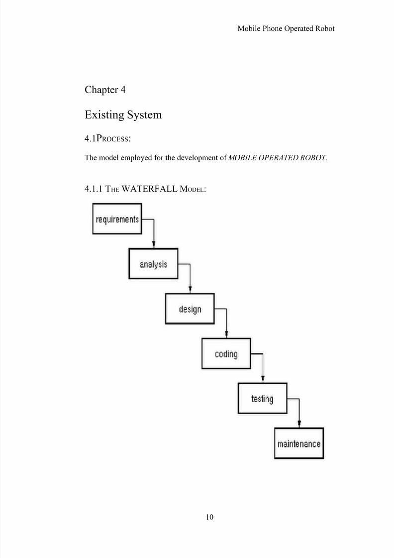
4.1PROCESS:
The model employed for the development of MOBILE OPERATED ROBOT.
4.1.1 THE WATERFALL MODEL:
10
8/3/2019 Shaggy
http://slidepdf.com/reader/full/shaggy 11/38
Mobile Phone Operated Robot
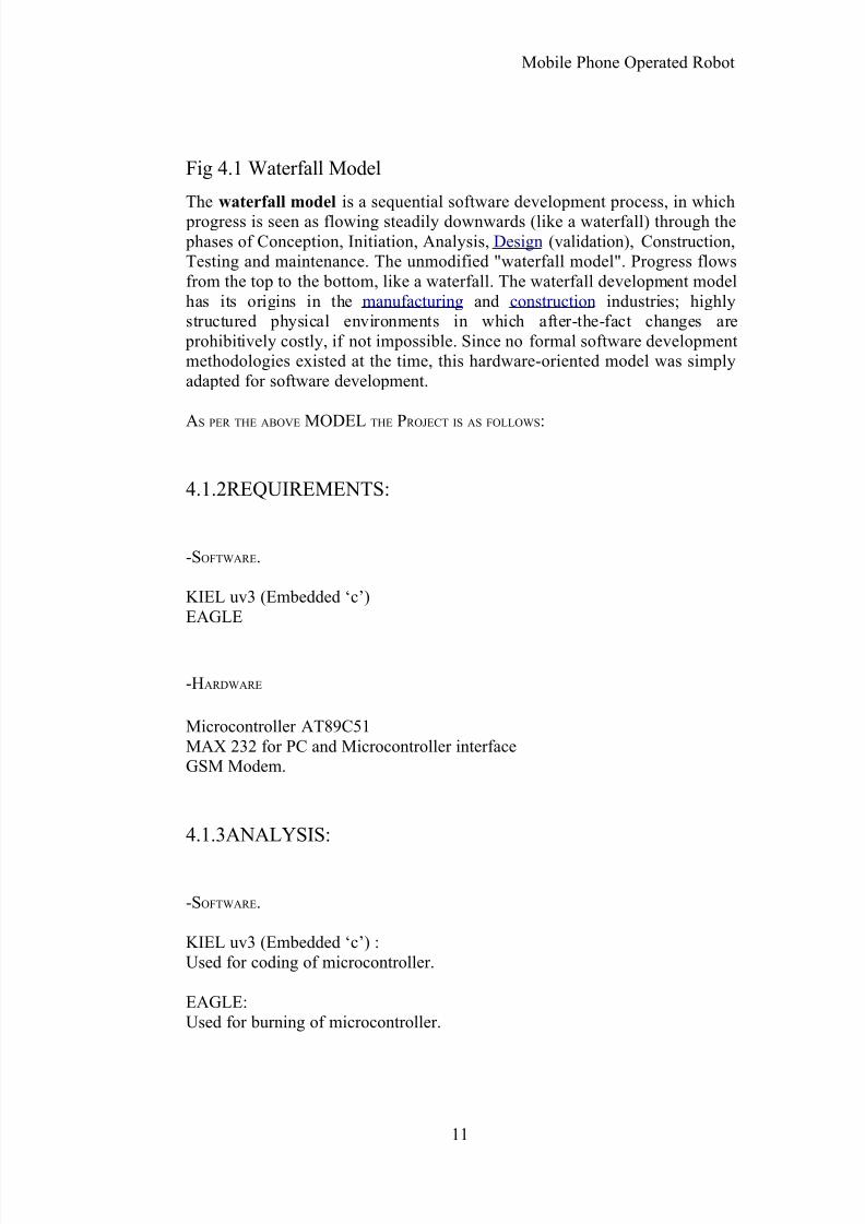
Fig 4.1 Waterfall Model
The waterfall model is a sequential software development process, in which progress is seen as flowing steadily downwards (like a waterfall) through the phases of Conception, Initiation, Analysis, Design (validation), Construction,Testing and maintenance. The unmodified "waterfall model". Progress flowsfrom the top to the bottom, like a waterfall. The waterfall development modelhas its origins in the manufacturing and construction industries; highlystructured physical environments in which after-the-fact changes are
prohibitively costly, if not impossible. Since no formal software developmentmethodologies existed at the time, this hardware-oriented model was simplyadapted for software development.
AS
PER
THE
ABOVE
MODELTHE
PROJECT
IS
AS
FOLLOWS
:
4.1.2REQUIREMENTS:
-SOFTWARE.
KIEL uv3 (Embedded ‘c’)EAGLE
-HARDWARE
Microcontroller AT89C51MAX 232 for PC and Microcontroller interfaceGSM Modem.
4.1.3ANALYSIS:
-SOFTWARE.
KIEL uv3 (Embedded ‘c’) :Used for coding of microcontroller.
EAGLE:Used for burning of microcontroller.
11
8/3/2019 Shaggy
http://slidepdf.com/reader/full/shaggy 12/38
Mobile Phone Operated Robot
-HARDWARE.
8051 microcontroller:Four 8-bit ports.
DTMF Decoder:CM8870- CMOS Integrated DTMF Receiver.CM8870C is fully compatible with CM8870 for 18-pinDevices by grounding pins 5 and 6.
L293D motor driver:L293D is a PUSH-PULL FOUR CHANNEL DRIVER WITH DIODES.
Two mobiles with two GSM sim cards.
12

8/3/2019 Shaggy
http://slidepdf.com/reader/full/shaggy 13/38
Mobile Phone Operated Robot
4.1.3DESIGN:
Fig.4.2 Schematic Representation [2]
13

8/3/2019 Shaggy
http://slidepdf.com/reader/full/shaggy 14/38
Mobile Phone Operated Robot
Fig4.3 DTMF TABLE [2]
4.2TESTING:
The testing is performed on the system to determine its accuracy.
4.3MAINTENANCE:
The maintenance of the system depends upon user. The user should always beaware of the circuit’s maintenance
4.4 W5HH PRINCIPAL:
• Why is the system being developed? In order to represent the robotictechnology in the field of wireless communication for unlimited range.In the present age of robotic-technology, it is very necessary to developsome or the other technology that makes the maximum use of robot tohelp people do their work in an efficient way in their day to day life
14
8/3/2019 Shaggy
http://slidepdf.com/reader/full/shaggy 15/38
Mobile Phone Operated Robot
• What will be done, by when?
Acquiring the resources.: 10-12 days (approx.)
Assembling of the resources.: 4-6 days (approx.)
Code generation, modification, reuse.: 45-60 days(approx.)
Testing.: 7-10 days (approx.)
• Who is responsible for a
function?
As aforementioned, all the team members are collectively putting aneffort in all the possible aspects of this venture.
• Where they are
organizationally located?
As stated earlier, the customer, the user, and the developer all form a part of the team working on this project.
• How will the job be done
technically and managerially?
4.5 Technically: 8051 microcontroller.
DTMF Decoder-CM8870.
L293D motor driver.
Two mobiles with two GSM sim cards
15

8/3/2019 Shaggy
http://slidepdf.com/reader/full/shaggy 16/38
Mobile Phone Operated Robot
How much of each resource is needed?
Requirement Estimated Quantity
Mobile phones 2
GSM sim card 2
DC motor 2
DTMF decoder 1
8051 microcontroller 1
L293D motor driver 1
Breadboard 1
Spare Wires ½ m.
Conclusion:
Thus we had an overview of the existing systems.
16
8/3/2019 Shaggy
http://slidepdf.com/reader/full/shaggy 17/38
Mobile Phone Operated Robot
Chapter 5
Preliminary Design
5.1SOFTWARE DEVELOPMENT METHODS
UML is not a development method by itself, however, it was designed to be
compatible with the leading object-oriented software development methods of its time (for example OMT, Booch method, Objector ). Since UML hasevolved, some of these methods have been recast to take advantage of the newnotations (for example OMT), and new methods have been created based onUML. The best known is IBM Rational Unified Process (RUP). There aremany other UML-based methods like Abstraction Method, Dynamic SystemsDevelopment Method, and others, designed to provide more specific solutions,or achieve different objectives.
5.2MODELING
It is very important to distinguish between the UML model and the set of diagrams of a system. A diagram is a partial graphical representation of asystem's model. The model also contains a "semantic backplane" — documentation such as written use cases that drive the model elements anddiagrams.
UML diagrams represent two different views of a system model:
• Static (or structural) view: Emphasizes the static structure of thesystem using objects, attributes, operations and relationships. The
structural view includes class diagrams and composite structurediagrams.
• Dynamic (or behavioral) view: Emphasizes the dynamic behavior of the system by showing collaborations among objects and changes tothe internal states of objects. This view includes sequence diagrams,activity diagrams and state machine diagrams.
UML models can be exchanged among UML tools by using the XMIinterchange format.
17
8/3/2019 Shaggy
http://slidepdf.com/reader/full/shaggy 18/38
Mobile Phone Operated Robot
OUTLINE
• Visual modeling.
5.3 PROBLEM STATEMENT:
Even the Robot can function to do any work as ordered by its brain.The robot operates using stepper motors while allowing it to faster to the left,right, forward and reverse, rotate 360 degree. It’s easier to be used especiallyto carry the goods but can which have a certain limit of carrying.The idea of it came after seeing the difficulties of human being whom have towipeOut the energy and time by doing ordinary works such as carrying, unloading,
or Transferring goods. Here the ideal thought of producing something which canreplace allthose works to save energy and time.
AFTER READING THE ABOVE PROBLEM STATEMENT, FIND:
1. Actors2. Use cases with each actor 3. Find extends or uses use cases (if applicable)4. Finally: draw the main use case diagram
18
8/3/2019 Shaggy
http://slidepdf.com/reader/full/shaggy 19/38
Mobile Phone Operated Robot
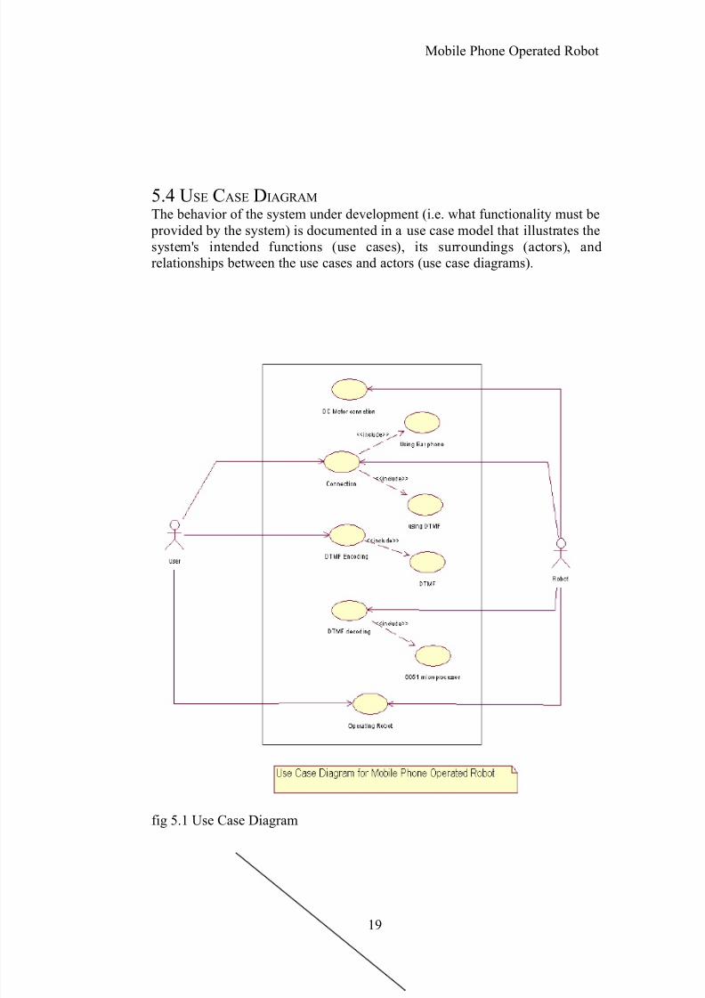
5.4 USE CASE DIAGRAM
The behavior of the system under development (i.e. what functionality must be provided by the system) is documented in a use case model that illustrates thesystem's intended functions (use cases), its surroundings (actors), andrelationships between the use cases and actors (use case diagrams).
fig 5.1 Use Case Diagram
19
8/3/2019 Shaggy
http://slidepdf.com/reader/full/shaggy 20/38
Mobile Phone Operated Robot
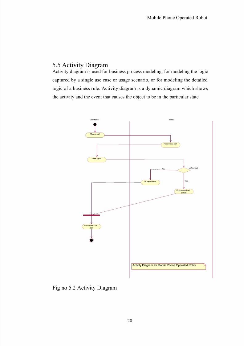
5.5 Activity DiagramActivity diagram is used for business process modeling, for modeling the logic
captured by a single use case or usage scenario, or for modeling the detailed
logic of a business rule. Activity diagram is a dynamic diagram which shows
the activity and the event that causes the object to be in the particular state.
Activity Diagram for Mobile Phone Operated Robot
Make a call
Gives input
Disconnect the
call
Receives a call
Valid input
Do the required
action
YesNo operation
No
RobotUser Mobile
Fig no 5.2 Activity Diagram
20

8/3/2019 Shaggy
http://slidepdf.com/reader/full/shaggy 21/38
Mobile Phone Operated Robot
5.4.2 Sequence Diagram:
The sequence diagram shows the pattern of interaction among the object
emphasizing the sequencing of message. Sequence Diagram is an easy and
intuitive way of describing the behaviors of a system by viewing the
interaction between system and environment. Sequence diagram describe
interaction among classes in terms of an exchange of message over time. It is
made of object and message.
: U s e r : U s e r
M o b i l e p h o n eM o b i l e p h o n e D T M F d e c o d e r D T M F d e c o d e r
: R o b o t: R o b o t
8 9 c 5 18 9 c 5 1
M a k e s a c a l l
D e c o d e d s i g n a l
C o m m a n d t o r o b o t
E n c o d e d s i g n a l
P e r f o r m s t h e a
Fig no 5.2 Sequence diagram
21
8/3/2019 Shaggy
http://slidepdf.com/reader/full/shaggy 22/38
Mobile Phone Operated Robot
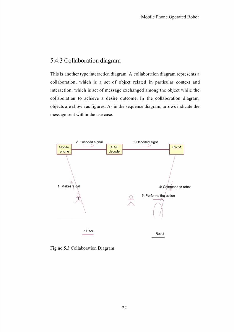
5.4.3 Collaboration diagram
This is another type interaction diagram. A collaboration diagram represents a
collaboration, which is a set of object related in particular context and
interaction, which is set of message exchanged among the object while the
collaboration to achieve a desire outcome. In the collaboration diagram,
objects are shown as figures. As in the sequence diagram, arrows indicate the
message sent within the use case.
Mobile
phone
DTMF
decoder
89c51
: User : Robot
1: Makes a call
2: Encoded signal 3: Decoded signal
4: Command to robot
5: Performs the action
Fig no 5.3 Collaboration Diagram
22
8/3/2019 Shaggy
http://slidepdf.com/reader/full/shaggy 23/38
Mobile Phone Operated Robot
Conclusion: Thus we completed with the preliminary design of
the project
Chapter 6
Requirement Analysis
6.1 Software Section
The Program Embedded C is used for I/O programming in 8051 along with
KEIL uvision which is a C compiler used for coding microcontroller.
6.2 Hardware Section
To build the transmitter and receiver circuit for wireless communication between Mobile and robot. To build the relay circuits to enable DC motor tooperate after receiving the Signal from receiver. To build the control motor circuit for control the dc motor perfectly (robot’s Movement).
6.3 Communication Interface
The communication interfaces include mobile phones with
GSM cards, the bread board containing DTMF decoder,
microcontroller chip and the motor driver.
6.4 Assumptions
The network of the service provider will always be maximum.
6.5 DependenciesFull working of the robot is dependent on the availability of network of theservice provider.
6.6 Integrity
23
8/3/2019 Shaggy
http://slidepdf.com/reader/full/shaggy 24/38
Mobile Phone Operated Robot
The design shall provide the capability to generate moreactions based on future requirements of the robot.
6.7 ORGANIZING THE SPECIFICREQUIREMENTS
Features:• Convenient
• Expandable
• Supports modularity• Easy maintenance
• Easily portable
• High reusability
Conclusion: Thus we studied the requirement analysis of the
system.
24
8/3/2019 Shaggy
http://slidepdf.com/reader/full/shaggy 25/38
Mobile Phone Operated Robot
Chapter 7
Development Tools
7.1 GOLDEN R ULES FOR USER I NTERFACE DESIGN:-
Place the user in control.
1. Reduce the user’s memory load.
2. Make the interface consistent.
These golden rules actually form the basis for a set of user interface design principlesthat guide this important software design activity.
7.2TASK A NALYSIS AND MODELLING:
The most important thing about the undertaken endeavor is that the major partof it consists of Software, thereby differentiating itself in terms of steps to betaken for task analysis, as compared to other conventional software ventures.
Password Management for Personalize network solves this problem by providing a secure system to Store, Administer, and Share passwords. Soconsidering the above defined context, following are the possible major tasksinvolved while implementing such system.
• Assembling and Interfacing of the different Modules, and
• Compilation and Execution of the computational algorithms.
• Training the network to be precise in its Diagnosis.
Only the above mentioned tasks capture the entire implementation as well asthe functional view of Password Manager
Now the first major task of “Assembling and Interfacing”, can be further refined into number of diminutive steps as follows:
• Write different code for three major Decision Making Criteria’s
25
8/3/2019 Shaggy
http://slidepdf.com/reader/full/shaggy 26/38
Mobile Phone Operated Robot
.
• Plan and implement a precise C4.5 algorithm
• Also plan a suitable function for feature extraction.
• Proper Interfacing between all these different modules.The second major task of “Compilation and Execution”, can be refined asfollows.
• Supplying Data Sets to the KEIL software.
• Run the compilation code as the network is trained.
• Look out for any errors and debug if possible.
• Execute the entire system again with a new Data Set to produce aflawless result.
7.3I NTERFACE DESIGN ACTIVITIES:
For our project, there really is scope and need for a user interface, since all the possible alterations, interactions and actions from the user side, can be handled by the EMBEDDED C..User interface is absolutely mandatory for the following conditions:
• When the prerequisites required for the successful execution of theend-product has not been provided by the Operating System.
• Assuming that the prerequisites are provided by the OS, but it involvesaccess and/or temporary modifications of the system files, which can
be detrimental, if not handled properly.
• Just for the sake of user-friendliness.
Since our project does not necessarily fall into the category of those software,which absolutely needs a user interface for a user to interact with it, we willhave to consider the itself as the User Interface, and we will proceed with thefurther interface analysis based on the same.
7.4DEFINING I NTERFACE OBJECTS AND ACTIONS:Following are the various objects falling in the mentioned category
• Source Object: All the Data Sets provided to the software.
• Target Object: The KEIL software and its results placed into a text file.
• Application Object: EMBEDED C used for compilation and execution.
26
8/3/2019 Shaggy
http://slidepdf.com/reader/full/shaggy 27/38
Mobile Phone Operated Robot
7.5 DESIGN ISSUES:Following are some of the Design Issues for devising the user interface:
• System Response Time: Since there are only few software parts to dealwith, the user won’t have to wait too long neither will he have to behasty in his operating of the system.
The only thing user will have to anticipate is the final snooped display, which
can never go unnoticed, since it will be displayed on an at least, 15 inchmonitor.Even if there is a slight delay, then as will be provided in the manual, the onlyadjustment needs to be done is the hardware.
• User help facilities: The amount of help manual needed to for theoperation of KEIL is very low in terms of volume. Because, each andevery piece of hardware and software, would have gone throughintensive tests, before it is released officially.
• Also the hardware desired for the successful operation of the end product will be provided along with the compatible software codes,thereby eliminating the immense dependency on the help-manual.
• The system is itself comprised of software which has about only few
hundreds of codes, and which again will be tested before the release. And
there is no additional piece of syntactical code that needs to be added, for the
processing of the product.
But as a last resort, a simple text document, though comprehensive andconcise would be provided, where all the program related matters would beanswered, thus making it an ‘integrated help facility’ approach.
Some other design issues that normally accompanies other conventional products:
Help will be available as an all-inclusive and a precise textdocument, thus making it available all the time, while the
product is in use.
During the help session, a user can switch back to the originaloperation, just like any user does while operating any givensoftware.
27
8/3/2019 Shaggy
http://slidepdf.com/reader/full/shaggy 28/38
Mobile Phone Operated Robot
7.6 IMPLEMENTATION TOOLS:
As stated in all the previous analysis, the OS used for the product i.e.Windows, KEIL itself will be acting as a User Interface, due to very little andalmost negligible involvement of the product-driven commands or functionality, since the product itself has no need for these customizations.Due to reliance on the user interface, we have gained following advantages for the development of the system.
• Easy Availability of functions.
• Specialized tools for the user interface design helps even a lay man touse our product.
So all the required testing can be carried out on the KEIL itself.
7.7DESIGN EVALUATION:
As this is our last year project, we are assuming the role of both, the developer and the end user.Considering the OS and the user interaction required for the operation of the
product, following analysis has been made:
• There will be absolutely nil amount of training required for using the
product.
• The number of user tasks, are just limited to the execution of the singlecode, which will automatically hierarchically compile all the remaining
piece of code.
• Though the initial interaction would not incur much load on thesystem, but it is possible that the final output may need somewhat largeamount of processing power and memory space, for interruptedexecution.
The iterative study and evaluation for the interaction between the final product
and the MATLAB will be performed by us, only after the initial trial of thesystem is carried out.Thus after the meticulous analysis for the user interface design, the only
prerequisite required from the end user side is the ‘Acclimatization to the OS& KEIL’, which is only needed if the end-user has been following other operating systems, and for such case too, the user manual to get acquainted tothe new user will be provided by us.
28
8/3/2019 Shaggy
http://slidepdf.com/reader/full/shaggy 29/38
Mobile Phone Operated Robot
Conclusion:Thus we had an overview of the development tools required for
mobile phone operated robot.
Chapter 8
Estimation and Planning:
To achieve reliable cost and effort estimates, a number of options arise:
1. Delay estimation until late in the project (obviously, we can achieve 100%accurate estimates after the project is complete!).2. Base estimates on similar projects that have already been completed.3. Use relatively simple decomposition techniques to generate project cost andeffort estimates.4. Use one or more empirical models for software cost and effort estimation.
8.1 PROGRAM BASED ESTIMATION:
Lines of code and function points were described as measures from which productivity metrics can be computed. LOC and FP data are used in two waysduring software project estimation: (1) as an estimation variable to "size" eachelement of the software and (2) as baseline metrics collected from past
projects and used in conjunction with estimation variables to develop cost and
effort projections.
LOC and FP estimation are distinct estimation techniques. Yet both have anumber of characteristics in common. The project planner begins with a
bounded statement of software scope and from this statement attempts todecompose software into problem functions that can each be estimatedindividually. LOC or FP (the estimation variable) is then estimated for eachfunction. Alternatively, the planner may choose another component for sizingsuch as classes or objects, changes, or business processes affected.
29
8/3/2019 Shaggy
http://slidepdf.com/reader/full/shaggy 30/38
Mobile Phone Operated Robot
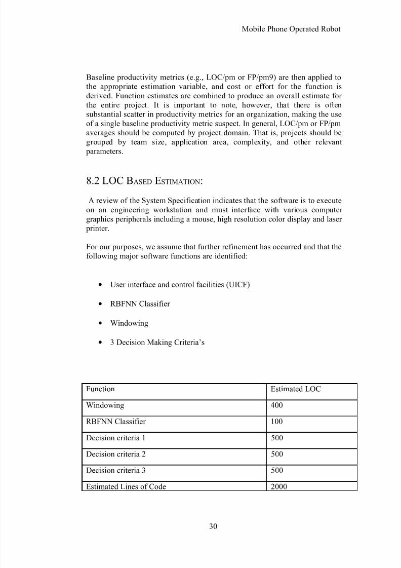
Baseline productivity metrics (e.g., LOC/pm or FP/pm9) are then applied tothe appropriate estimation variable, and cost or effort for the function is
derived. Function estimates are combined to produce an overall estimate for the entire project. It is important to note, however, that there is oftensubstantial scatter in productivity metrics for an organization, making the useof a single baseline productivity metric suspect. In general, LOC/pm or FP/pmaverages should be computed by project domain. That is, projects should begrouped by team size, application area, complexity, and other relevant
parameters.
8.2 LOC BASED ESTIMATION:
A review of the System Specification indicates that the software is to executeon an engineering workstation and must interface with various computer graphics peripherals including a mouse, high resolution color display and laser
printer.
For our purposes, we assume that further refinement has occurred and that thefollowing major software functions are identified:
• User interface and control facilities (UICF)
• RBFNN Classifier
• Windowing
• 3 Decision Making Criteria’s
Function Estimated LOC
Windowing 400
RBFNN Classifier 100
Decision criteria 1 500
Decision criteria 2 500
Decision criteria 3 500
Estimated Lines of Code 2000
30
8/3/2019 Shaggy
http://slidepdf.com/reader/full/shaggy 31/38
Mobile Phone Operated Robot
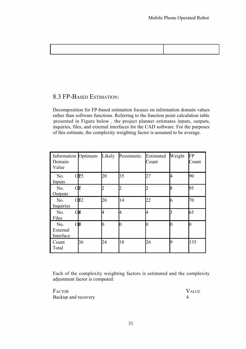
8.3 FP-BASED ESTIMATION:
Decomposition for FP-based estimation focuses on information domain valuesrather than software functions. Referring to the function point calculation table
presented in Figure below , the project planner estimates inputs, outputs,inquiries, files, and external interfaces for the CAD software. For the purposesof this estimate, the complexity weighting factor is assumed to be average.
InformationDomainValue
Optimum Likely Pessimistic EstimatedCount
Weight FPCount
No. Of
Inputs
25 20 35 27 4 90
No. Of Outputs
2 2 2 2 8 95
No. Of Inquiries
32 20 14 22 6 70
No. Of Files
4 4 4 4 3 65
No. Of ExternalInterface
0 0 0 0 0 0
CountTotal 36 24 18 26 9 135
Each of the complexity weighting factors is estimated and the complexityadjustment factor is computed:
FACTOR VALUE
Backup and recovery 4
31

8/3/2019 Shaggy
http://slidepdf.com/reader/full/shaggy 32/38
Mobile Phone Operated Robot
Data communications 2Distributed processing 0
Performance critical 4Existing operating environment 3On-line data entry 4Input transaction over multiple screens 5Master files updated on-line 3Information domain values complex 5Internal processing complex 5Code designed for reuse 4Conversion/installation in design 3Multiple installations 5Application designed for change 5
Complexity adjustment factor 1.17
Finally, the estimated number of FP is derived:
Festinated = count-total x [0.65 + 0.01 x _ (Fi)]
Festinated = 375
The organizational average productivity for systems of this type is 6.5 FP/pm.Based on a burdened labor rate of $8000 per month; the cost per FP isapproximately $1230. Based on the LOC estimate and the historical
productivity data, the total estimated project cost is $461,000 and theestimated effort is 58 person-months.
8.4 THE COCOMO MODEL
In his classic book on “software engineering economics,” Barry Boehm[BOE81] introduced a hierarchy of software estimation models bearing thename COCOMO, for COnstructive COst MOdel. The original COCOMOmodel became one of the most widely used and discussed software costestimation models in the industry. It has evolved into a more comprehensiveestimation model, called COCOMO II [BOE96, BOE00].
32
8/3/2019 Shaggy
http://slidepdf.com/reader/full/shaggy 33/38
Mobile Phone Operated Robot
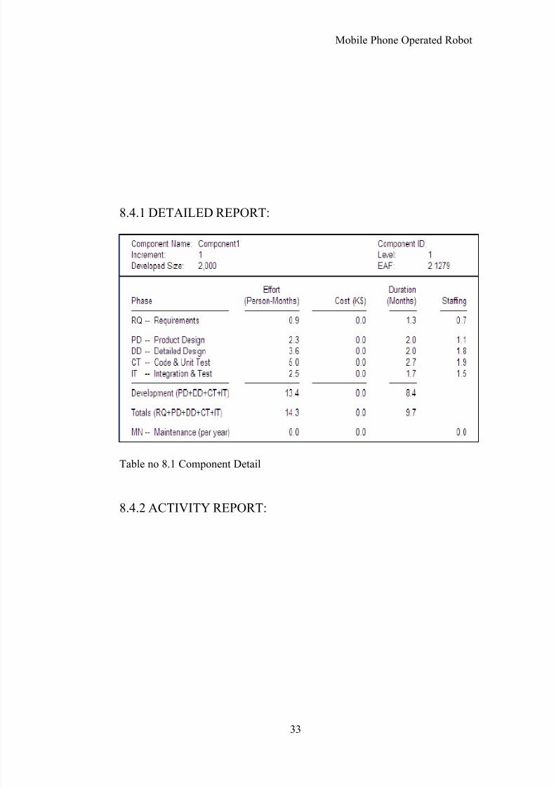
8.4.1 DETAILED REPORT:
Table no 8.1 Component Detail
8.4.2 ACTIVITY REPORT:
33
8/3/2019 Shaggy
http://slidepdf.com/reader/full/shaggy 34/38
Mobile Phone Operated Robot
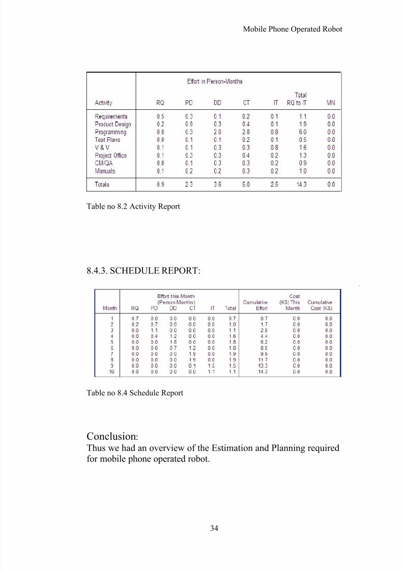
Table no 8.2 Activity Report
8.4.3. SCHEDULE REPORT:
Table no 8.4 Schedule Report
Conclusion:
Thus we had an overview of the Estimation and Planning requiredfor mobile phone operated robot.
34
8/3/2019 Shaggy
http://slidepdf.com/reader/full/shaggy 35/38
Mobile Phone Operated Robot
Chapter 9
Proposed system
9.1 SystemIn the present project the robot is controlled by a mobile phone which makes
a call to the mobile phone attached to the robot. In the course of a call if any
button is pressed a tone corresponding to the button pressed is heard at the
other end of the call. This tone is called DTMF tone. The robot perceives this
DTMF tone with the help of a phone stacked in the robot. The processing of
the received tone is done by Atmega 32 microcontroller with the help of
DTMF decoder, HT9170. The decoder decodes the DTMF tone in to its
equivalent binary digit and this binary number is sent to the
microcontroller. The microcontroller is preprogrammed to take a decision for
any given input. The microcontroller outputs its decision to motor drivers to
drive the motors in order to have forward or backward motion or a turn. Any
mobile which makes a call to the mobile phone stacked in the robot will act
as remote. So, this is a simple robotic project which even does not require the
construction of receiver and transmitter kits, but has an innovated application
of cell phone and robust control.
35
8/3/2019 Shaggy
http://slidepdf.com/reader/full/shaggy 36/38
Mobile Phone Operated Robot
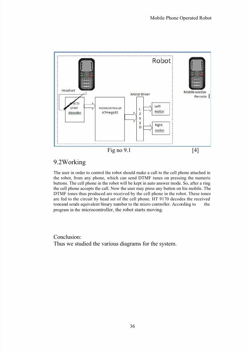
Fig no 9.1 [4]
9.2Working
The user in order to control the robot should make a call to the cell phone attached inthe robot, from any phone, which can send DTMF tunes on pressing the numeric
buttons. The cell phone in the robot will be kept in auto answer mode. So, after a ringthe cell phone accepts the call. Now the user may press any button on his mobile. TheDTMF tones thus produced are received by the cell phone in the robot. These tonesare fed to the circuit by head set of the cell phone. HT 9170 decodes the receivedtoneand sends equivalent binary number to the micro controller. According to the
program in the microcontroller, the robot starts moving.
Conclusion:
Thus we studied the various diagrams for the system.
36
8/3/2019 Shaggy
http://slidepdf.com/reader/full/shaggy 37/38
Mobile Phone Operated Robot
Chapter 10
REFERENCES
1. Wikipedia - The free encyclopedia 2. http://www.8051projects.info/ 3. http://www.instructables.com/
37
8/3/2019 Shaggy
http://slidepdf.com/reader/full/shaggy 38/38
Mobile Phone Operated Robot
4. Schenker, L (1960), "Pushbutton Calling with a Two-GroupVoice-Frequency Code", The Bell system technical journal 39 (1):
235–255, ISSN 0005-8580 5. “DTMF Tester” , ‘Electronics For You’ Magazine , Edition(June 2003) 6. http://www.alldatasheet.com/ 7. http://www.datasheet4u.com/
8. http://www.datasheetcatalog.com/