Shadow Impact Module SIM - Douglas Alarm Function ... 4 Technical Documentation ... shadow impact...
56
Shadow Impact Module SIM Manual for Version 3.0 Software Version 4.4 Windtest NorthTec GmbH Kaiser-Wilhelm-Koog GmbH
Transcript of Shadow Impact Module SIM - Douglas Alarm Function ... 4 Technical Documentation ... shadow impact...
Shadow Impact Module SIM
Manual for Version 3.0
Software Version 4.4
Windtest
NorthTec GmbH Kaiser-Wilhelm-Koog GmbH

2 User Manual, Version 3.0
Manual for Shadow Impact Module Version 3.0
Software Version 4.4
1. Edition, March 2004
Sales and Project Coordination:
WINDTEST Kaiser-Wilhelm-Koog GmbHDipl.-Ing. Jörg NeubertSommerdeich 14 b25709 Kaiser-Wilhelm-KoogGermany
Tel.: +49 4856 901 0 Fax: +49 4856 901 49
Email: [email protected] Internet: www.windtest.de
Development, Manufacture and Installation:
NorthTec GmbHHorsbeker Weg 224980 Schafflund
Tel.: +49 700 66784832 (NORTHTEC)Email: [email protected]: www.northtec.de
Shadow Impact Module Manual 3
Table of Contents
1 Product Description ............................................................................... 6
1.1 Applications........................................................................................................................6
1.2 Installing the Shadow Impact Module .................................................................................7
1.3 Functionality .......................................................................................................................8
1.3.1 Shadow Impact Calculation..........................................................................................8
1.3.2 Light Sensors...............................................................................................................8
1.3.3 Shut-Down of Wind Turbine Generators ......................................................................8
1.4 Configuration of the Shadow Impact Module ......................................................................9
1.5 Log Function (optional).....................................................................................................10
1.6 Azimuth Function (optional) ..............................................................................................10
1.7 Alarm Function (optional) .................................................................................................11
1.8 Language Selection (optional) ..........................................................................................11
2 Menu Navigation................................................................................... 12
2.1 Status Display (Menu 1) ...................................................................................................13
2.1.1 WTG Operating Status Display (Menu 1.1) ................................................................13
2.1.2 Light Sensor Status Display (Menu 1.2) .....................................................................14
2.1.3 Daily and Annual Counter Display (Menu 1.3)............................................................14
2.1.4 Position of the Sun Display (Menu 1.4) ......................................................................15
2.1.5 Software Version Display (Menu 1.5) .........................................................................15
2.1.6 Selecting Parameters for the Alarm Function (Menu 1.6) ...........................................15
2.1.6.1 Alarm Status Display (Menu 1.6.1) ......................................................................16
2.1.6.2 RCC Alarm Counter Display (Menu 1.6.2) ...........................................................16
2.1.7 Rotor Azimuth Display (Menu 1.7) .............................................................................16
2.2 Settings (Menu 2) .............................................................................................................17
2.2.1 Selecting Setting Options (Menu 2.1).........................................................................18
2.2.1.1 Setting Date and Time Manually (Menu 2.1.1).....................................................18
2.2.1.2 Setting Date and Time by the RCC module (Menu 2.1.2) ....................................19
2.2.2 Selecting Setting Options (Menu 2.2).........................................................................19
2.2.2.1 Data Storage (Menu 2.2.1) ..................................................................................20

4 User Manual, Version 3.0
2.2.2.2 Setting the Storage Mode (Menu 2.2.2) ...............................................................20
2.2.2.3 Reset to Default Settings (Menu 2.2.3) ................................................................21
2.2.2.4 Storage Check (Menu 2.2.4)................................................................................21
2.2.2.5 Log Data (Menu 2.2.5).........................................................................................22
2.2.3 Setting the Location (Menu 2.3) .................................................................................22
2.2.4 Selecting the Place of Immission to Be Set (Menu 2.4) ..............................................23
2.2.4.1 Selection of Setting Options (Menu 2.4.1)............................................................23
2.2.4.1.1 Entering the Height a. Sea Level for a Place of Immission (Menu 2.4.1.1) ......24
2.2.4.1.2 Entering the Wall of a Place of Immission (Menu 2.4.1.2) ...............................24
2.2.4.1.3 Entering the Areas of a Place of Immission (Menu 2.4.1.3).............................26
2.2.4.1.4 Entering the Permitted Load Times (Menu 2.4.1.4) .........................................27
2.2.4.1.5 Setting the Annual Counter (Menu 2.4.1.5) .....................................................27
2.2.4.1.6 Setting the Beginning of the Year (Menu 2.4.1.6)............................................28
2.2.5 Selecting the Wind Turbine Generator to Be Set (Menu 2.5)......................................29
2.2.5.1 Selection of Setting Options (Menu 2.5.1)............................................................29
2.2.5.1.1 Entering the Hub Height of the Wind Turbine Generator (Menu 2.5.1.1) .........29
2.2.5.1.2 Entering the Rotor Radius (Menu 2.5.1.2).......................................................30
2.2.5.1.3 Entering the Altitude of the Wind Turbine Generator (Menu 2.5.1.3) ...............30
2.2.5.1.4 Entering the Coordinates of the Wind Turbine Generator (Menu 2.5.1.4)........30
2.2.5.1.5 Control (Menu 2.5.1.5) ....................................................................................31
2.2.5.1.6 Entering the Follow-up Time for the Wind Turbine Generator (Menu 2.5.1.6) .32
2.2.5.1.7 Sound Option Selection (Menu 2.5.1.7) ..........................................................33
2.2.5.1.7.1 Shut-Down by Date (Menu 2.5.1.7.1)........................................................33
2.2.5.1.7.2 Shut-Down by Day of the Week (Menu 2.5.1.7.2) .....................................34
2.2.6 Combinations (Menu 2.6)...........................................................................................36
2.2.6.1 Generating the Combinations (Menu 2.6.1.1) ......................................................36
2.2.6.2 Setting the Status of the Combinations (Menu 2.6.2)...........................................36
2.2.7 Selecting the Light Sensor Settings (Menu 2.7) .........................................................37
2.2.7.1 Entering the Number of Light Sensors (Menu 2.7.1.) ...........................................37
2.2.7.2 Adjusting the Sensors (Menu 2.7.2).....................................................................38
Shadow Impact Module Manual 5
2.2.7.3 Entering a Hysteresis (Menu 2.7.3) .....................................................................38
2.2.8 Miscellaneous (Menu 2.8) ..........................................................................................39
2.2.8.1 Setting the Password (Menu 2.8.1)......................................................................39
2.2.8.2 Parameters for the Alarm Function (Menu 2.8.2) .................................................40
2.2.8.2.1 Entering the Alarm Output (Menu 2.8.2.1)......................................................40
2.2.8.2.2 Clearing an Alarm (Menu 2.8.2.2) ..................................................................40
2.2.8.2.3 Setting the RCC Limit Value (Menu 2.8.2.3) ...................................................41
2.2.8.3 Parameters for the Azimuth Function (Menu 2.8.3)..............................................41
2.2.8.3.1 Setting the Azimuth Tolerance (Menu 2.8.3.1) ................................................42
2.2.8.3.2 Setting the Azimuth Offset (Menu 2.8.3.2) ......................................................42
2.2.8.3.3 Entering the Hub Distance (Menu 2.8.3.3) ......................................................43
2.2.8.3.4 Entering the Measuring Cycle (Menu 2.8.3.4) .................................................43
2.2.8.3.5 Entering the Number of Measurements (Menu 2.8.3.5)...................................44
2.2.8.4 Selecting the Menu Language (Menu 2.8.4) ........................................................44
2.2.9 Control Check (Menu 2.9) ..........................................................................................45
3 Maintenance of the Shadow Impact Module....................................... 46
4 Technical Documentation .................................................................... 46
4.1 General Specifications .....................................................................................................46
4.2 Fuses in Terminal Blocks .................................................................................................47
4.3 Shadow Impact Module Vers. 3.0 Terminal Connections for 1 WTG ................................48
4.4 Shadow Impact Module Vers. 3.0 Terminal Connections for 6 WTGs...............................49
4.5 Light Sensor and RCC Connection...................................................................................50
5 Appendix ............................................................................................... 51
5.1 Configuration Example .....................................................................................................51
5.2 Example of a Log .............................................................................................................56

6 User Manual, Version 3.0
1 Product Description
1.1 Applications During sunny times of the day, the operation of wind turbine generators (WTG) may cause annoying periodic shadow impact to adjacent buildings. For this reason, building permits for the erection of WTGs increasingly demand the integration of automatic shut-down devices in order to prevent adjacent buildings from being impacted more than acceptable according to the recommended values. Normally, the authorities specify limit values regarding the maximum permitted daily and annual load.The shadow impact module introduced herein serves as a technical solution for meeting these demands. A single shadow impact module can monitor up to 12 wind turbine generators in up to 100 places of immission (PI). If the limit values are exceeded in a place of immission, the WTG responsible is shut down for the duration of the shadow impact. Furthermore, the preload caused by up to 38 WTGs can be considered. In case the number of wind turbine generators to be monitored exceeds the maximum number of wind turbine generators controllable by a single shadow impact module, several shadow impact modules may be operated in parallel.As an option, the shadow impact module provides for storage of all shadow impact events of at least one year in a first-in-first-out memory. The data collected include information on theoretical and actual shadow impact in the places of immission (listed with time and date of occurrence) as well as information on whether the limit value exceedances have resulted in wind turbine generator shut-downs. Using the serial interface of the shadow impact module and the Shadow Memory software, the data collected may be transmitted to a computer where they can be displayed or printed out in tabular format. Modifying the data is not possible.Another optional feature of the shadow impact module is the shut-down of wind turbine generators at fixed points in time as it may be necessary in order to prevent noise emission during night time. For each day of the week and for each wind turbine generator individually, a period of time can be specified during which the wind turbine generators will be shut down. Furthermore, it is possible to specify shut-down periods for specific dates. These shut-downs can be recorded as well.

Shadow Impact Module Manual 7
1.2 Installing the Shadow Impact Module The shadow impact module is integrated in a steel cabinet with protection class IP65. It is installed on the inside of the wind turbine generator. A mains supply (230 V AC) must be available for voltage supply to the shadow impact module.The light sensor and the radio controlled clock (RCC module) are installed outside of the wind turbine generator. The light sensor comes mounted on a cantilever. The cantilever is secured to the south side of the tower. Depending on the tower type, it can be mounted using stainless clamps or heavy-duty dowels. For connecting the light sensor and the RCC module to the shadow impact module, a drilling hole in the tower or an accessible empty conduit must be available for the connection cable.If desired, the light sensor can be supplied mounted on a mast. In this case, the mast must be erected south of the wind turbine generator in order to exclude shadowing effects on the light sensor caused by the wind turbine generator tower.Alternatively, the light sensor may be installed on top of the wind turbine generator nacelle. When choosing this type of installation, a shielded control line (7 x 0.5 mm²) must be provided for the connection of the light sensor located on top of the nacelle to the shadow impact module located in the tower feet.In principle, when choosing a location for the light sensor, it should be ensured that shadowing effects on the light sensor caused by wind turbine generator components, trees or other kinds of obstacles are avoided. When choosing a location for the RCC module it should be ensured that the front of the module points towards the emitter sending out the time signal (e.g. Frankfurt/Main for Germany). For information on connection of the light sensor and the RCC module to the shadow impact module, please refer to Chapter 4.4.For each wind turbine generator to be shut down by the shadow impact module when required, a floating relay contact (normally closed contact/normally open contact) is provided. In case several wind turbine generators are to be monitored by the shadow impact module, networking the wind turbine generators using copper cables or fibre optic cables is required. Each additional wind turbine generator to be monitored requires two copper cable wires or one optical fibre. When the wind turbine generators are monitored using fibre optic cables, external converter modules must be employed for signal conversion. The connections of the switching outputs are illustrated in sections 4.2 and 4.3. If a shadow impact module is to monitor more than one wind turbine generator, it is provided with an additional power supply unit (PSU2). The output voltage serves for activating coupling relays via telecommunication cables.

8 User Manual, Version 3.0
1.3 Functionality One shadow impact module can take into account shadow impact in up to 100 places of immission. Since the authorities usually specify limit values for daily and annual shadow impact, there is a daily as well as an annual counter for each place of immission. For each of these counters, you can set a limit value. As soon as shadow impact is detected in one of these places of immission, the respective counters will be updated in cycles of one minute. If one of the counters reaches its limit value, the wind turbine generator causing the shadow impact is shut down. Once the rotor shadow has passed the place of immission or the light intensity has become too low to cause real shadow impact, the wind turbine generator is released. Shadow impact effects at a sun height angle of < 3° are not taken into account.The annual period surveyed can be defined for each place of immission individually. In places of immission where shadow impact effects may occur all year round, setting the start of the annual period surveyed to the start of the strong wind period is an obvious choice. This way, shut-down hours during the strong wind periods due to exceedance of the maximum permitted annual immission can be reduced. As a result, these shut-down events are shifted to the summer months.
1.3.1 Shadow Impact Calculation The shadow impact module cyclically determines the position of the sun. Using the position of the sun as well as the wind turbine generator data entered, the position and the size of the rotor shadow is calculated. The results of this calculation are then compared to the positions of the places of immission. Thus, the shadow impact module knows at any time, whether shadow impact effects are theoretically possible in one or more places of immission.The exact time of day is a prerequisite for reliable shadow impact calculations. Therefore, the shadow impact module is provided with a radio controlled clock (RCC module).
1.3.2 Light Sensors In order to determine whether shadow impact effects are actually possible, the shadow impact module is provided with one or more light sensors. The light sensors enable the assessment of the light conditions. The rotor shadow will be perceived only if the direct sun radiation is strong enough.
1.3.3 Shut-Down of Wind Turbine Generators A wind turbine generator is shut down only if real shadow impact effects occur in a place of immission exceeding a shadow impact limit value.If the shadow impact is eliminated due to cloudiness after a wind turbine generator has been shut down, the wind turbine generator is released. In order to prevent a wind turbine generator from being shut down and released in short intervals due to unstable weather conditions, you can define a follow-up time. As a result of setting a follow-up time, a wind turbine generator shut down by the shadow impact module is not released as soon as the sky clouds over. Only after the follow-up time has elapsed or shadow impact is no longer possible (according to the shadow impact calculation), the wind turbine generator is released. By setting a follow-up time, you can reduce the wear and tear on the wind turbine generators.
Shadow Impact Module Manual 9
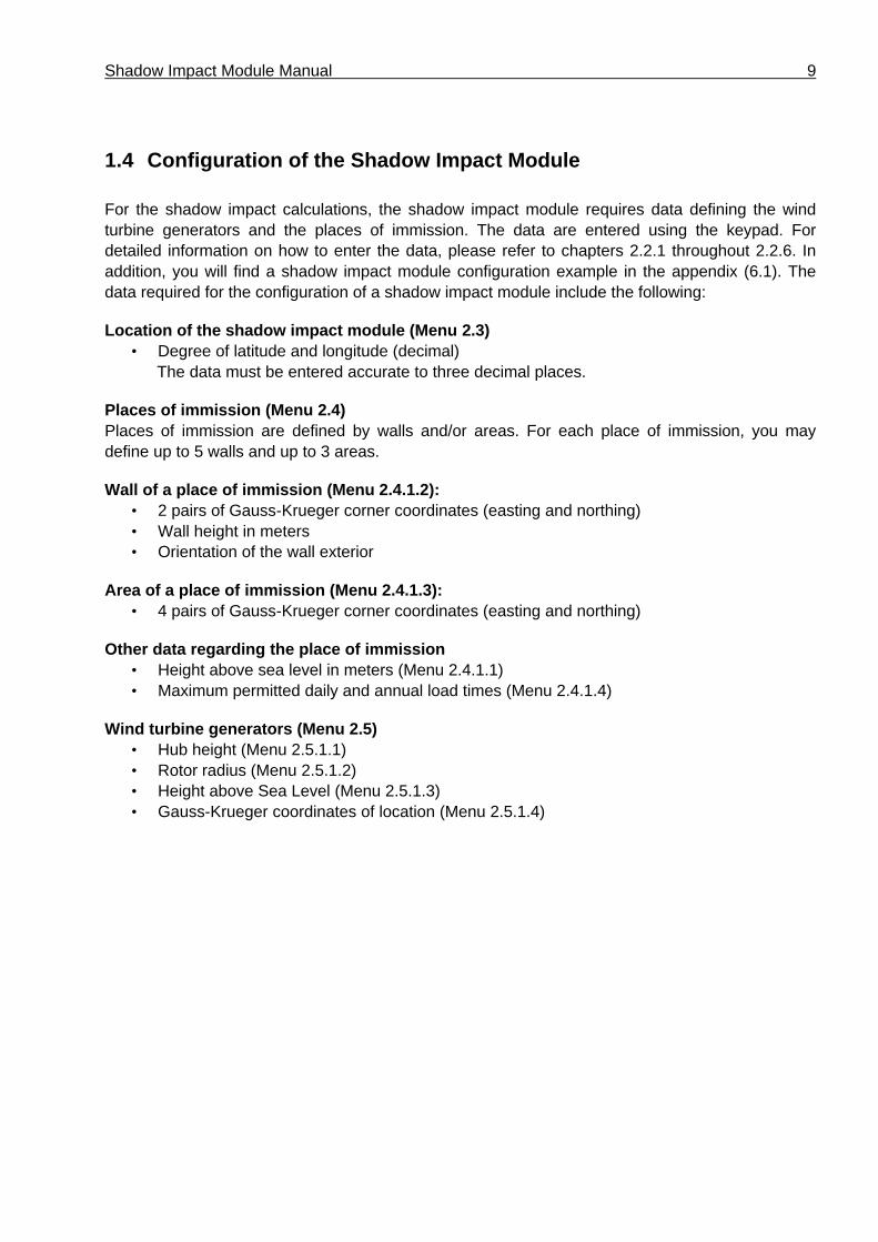
1.4 Configuration of the Shadow Impact Module
For the shadow impact calculations, the shadow impact module requires data defining the wind turbine generators and the places of immission. The data are entered using the keypad. For detailed information on how to enter the data, please refer to chapters 2.2.1 throughout 2.2.6. In addition, you will find a shadow impact module configuration example in the appendix (6.1). The data required for the configuration of a shadow impact module include the following:
Location of the shadow impact module (Menu 2.3) • Degree of latitude and longitude (decimal)
The data must be entered accurate to three decimal places.
Places of immission (Menu 2.4) Places of immission are defined by walls and/or areas. For each place of immission, you may define up to 5 walls and up to 3 areas.
Wall of a place of immission (Menu 2.4.1.2): • 2 pairs of Gauss-Krueger corner coordinates (easting and northing)• Wall height in meters• Orientation of the wall exterior
Area of a place of immission (Menu 2.4.1.3): • 4 pairs of Gauss-Krueger corner coordinates (easting and northing)
Other data regarding the place of immission • Height above sea level in meters (Menu 2.4.1.1)• Maximum permitted daily and annual load times (Menu 2.4.1.4)
Wind turbine generators (Menu 2.5) • Hub height (Menu 2.5.1.1)• Rotor radius (Menu 2.5.1.2)• Height above Sea Level (Menu 2.5.1.3)• Gauss-Krueger coordinates of location (Menu 2.5.1.4)
10 User Manual, Version 3.0
1.5 Log Function (optional) If the shadow impact module is provided with a log function, all shadow impact events are recorded. Each event is assigned a time stamp. The following events are logged:
• Shadow Impact The corresponding wind turbine generator causes real shadow impact in the corresponding place of immission.
• Theoretical Shadow Impact Theoretically, shadow impact may occur in the corresponding place of immission. However, the intensity of the direct sunlight is too low to cause actual shadow impact effects.
• End of Shadow Impact Since the sun has changed its position, the corresponding wind turbine generator can no longer cause actual shadow impact in the corresponding place of immission.
• Stop WTG The corresponding wind turbine generator was stopped by the shadow impact module.
• Start WTG The corresponding wind turbine generator was released.
For a log example, please refer to Appendix 6.2.
1.6 Azimuth Function (optional)
The shut-down periods of the wind turbine generators can be reduced to a minimum by taking into account the position of the rotor when calculating the duration of shadow impact. When the rotor is positioned at a right angle to the direction of the sun rays, the shadow ellipse of the rotor in the horizontal plane is at its maximum. As the position of the rotor changes towards the direction of the sunrays, the shadow ellipse reduces in size until only a small stripe remains.
The Azimuth function provides an analogue input for analysing the azimuth signal from the wind turbine generator. The input signal may be either a voltage or a current signal
The shadow impact log will indicate the wind direction for each invent.

Shadow Impact Module Manual 11
1.7 Alarm Function (optional)
The Alarm function provides an additional floating relay contact (normally closed contact/normally open contact) which can be used to verify that the shadow impact module is operating properly. During normal operation, the relay contact is active. If the power supply to the shadow impact module is interrupted or the monitoring routines of the shadow impact module detects a failure in the light sensor or radio controlled clock, this relay contact is released.
1.8 Language Selection (optional)
If Language Selection is enabled, you can choose between German or English user interface.
12 User Manual, Version 3.0
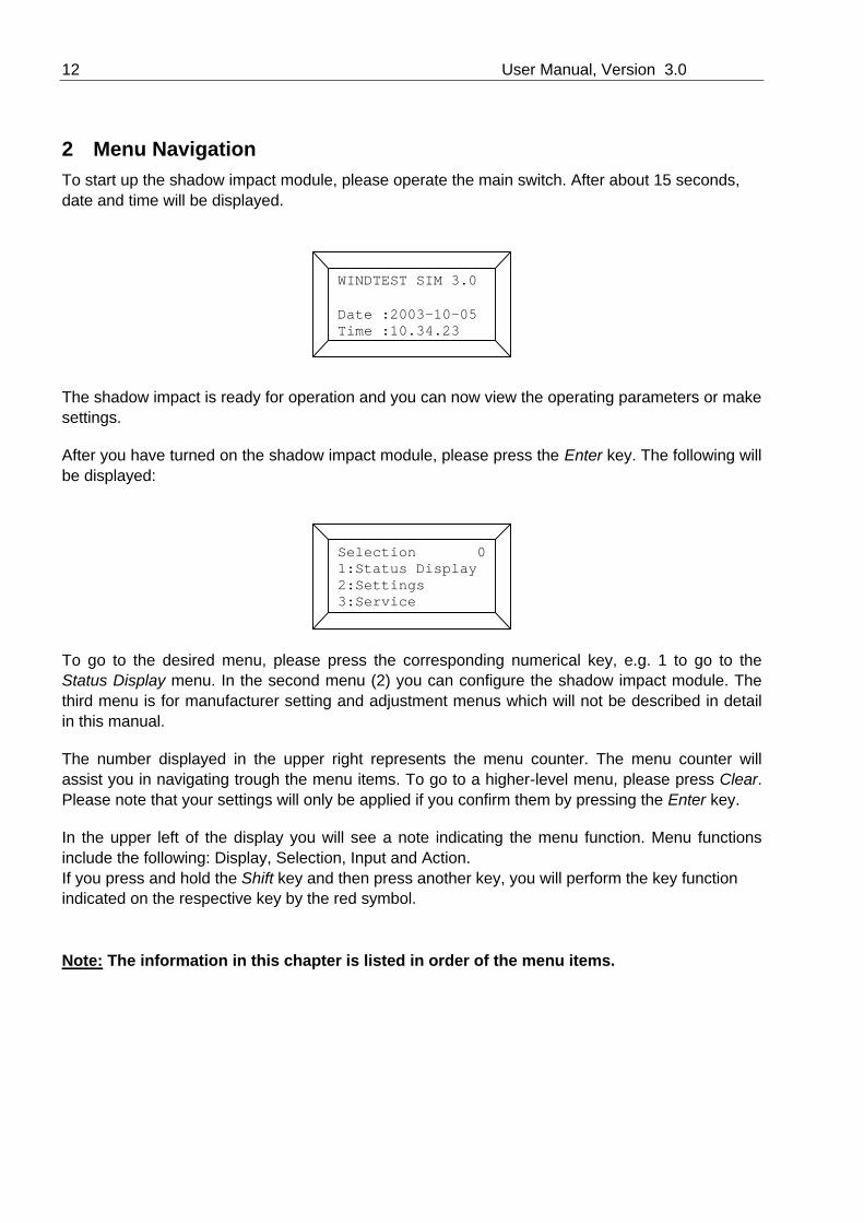
2 Menu Navigation To start up the shadow impact module, please operate the main switch. After about 15 seconds, date and time will be displayed.
The shadow impact is ready for operation and you can now view the operating parameters or make settings.
After you have turned on the shadow impact module, please press the Enter key. The following will be displayed:
To go to the desired menu, please press the corresponding numerical key, e.g. 1 to go to the Status Display menu. In the second menu (2) you can configure the shadow impact module. The third menu is for manufacturer setting and adjustment menus which will not be described in detail in this manual.
The number displayed in the upper right represents the menu counter. The menu counter will assist you in navigating trough the menu items. To go to a higher-level menu, please press Clear. Please note that your settings will only be applied if you confirm them by pressing the Enter key.
In the upper left of the display you will see a note indicating the menu function. Menu functions include the following: Display, Selection, Input and Action.If you press and hold the Shift key and then press another key, you will perform the key function indicated on the respective key by the red symbol.
Note: The information in this chapter is listed in order of the menu items.
WINDTEST SIM 3.0
Date :2003-10-05 Time :10.34.23
Selection 0 1:Status Display 2:Settings 3:Service

Shadow Impact Module Manual 13
2.1 Status Display (Menu 1)
In the Status Display menu, you may view various operating parameters. To go to the desired sub menu, just press the corresponding numerical key. Use the arrow keys to move up and down the selection list.
2.1.1 WTG Operating Status Display (Menu 1.1)
This display mode enables you to find out whether one of the wind turbine generators to be monitored is currently shut down by the shadow impact module.
The display shows that WTG 1 has been shut down by the shadow impact module (status = 0) whereas WTG 0 and WTG 2 have not been shut down (status = 1). Use the arrow keys to move up and down the list. The status information of 50 WTGs (0-49) is displayed, even though the shadow impact module cannot monitor all of the WTGs. The display refers only to the shadow impact module switching outputs (Menu 2.5.1.5) responsible for the corresponding WTG; it does not indicate the actual operating status of the WTG.
Please press Clear to return to the selection menu of the status display.
selection 1 1:WTG Status 2:Sensor Status 3:PI Counter
Display 1.1 Status WTG00: 1 Status WTG01: 0 Status WTG02: 1

14 User Manual, Version 3.0
2.1.2 Light Sensor Status Display (Menu 1.2)
The light sensors have the function of determining the direct portion of the visible sunlight. Actual
shadow impact is possible only if the direct portion is high enough. Menu 1.2 provides information on the light conditions at the respective light sensor. A status of 1 means that due to the light conditions, actual shadow impact is possible. With a status of 0, this is not possible.
Up to four light sensors may be connected to the shadow impact module. Using more than one light sensor is necessary in cases where the wind turbine generators are located far away from each other so that on days with slowly passing clouds there may be longer periods during which the light conditions at the wind turbine generators differ from each other. Employing a second light sensor may also serve the purpose of reducing the failure probability of the shadow impact module due to a damaged or dirty light sensor.
2.1.3 Daily and Annual Counter Display (Menu 1.3)
This display menu provides information on the load times of the places of immission.
The load times shown on the display are to be read as follows. On the current day, PI 0 has been impacted for a total of 15 minutes and during the current year it has been impacted for a total of 140 minutes. On the current day, PI 1 has not been impacted at all; however, during the current year it has been impacted for a total of 80 minutes. PI 2 has not been impacted so far, neither on the current day, nor in the course of the current year.
Regarding the load times, the switchable as well as the non-switchable WTGs are taken into account.The daily counter is reset to zero at midnight. The annual counter is reset to zero at the end of the year.
Use the arrow keys to move up and down the counter list.
Display 1.2 Sensor 0: 1 Sensor 1: 0 Sensor 2: 0
Display 1.3 PI00 15/0140min PI01 00/0080min PI02 00/0000min

Shadow Impact Module Manual 15
2.1.4 Position of the Sun Display (Menu 1.4)
This menu displays the position of the sun continuously determined according to time and date. The height angle and the azimuth (direction angle) of the sun are represented in degrees.
The height angle is measured between the horizontal plane and the sun. When the sun is at the zenith, the height angle is 90°. At the horizon, the height angle is 0°. The azimuth of the sun is measured along the horizon in clockwise direction from north where it is 0°. (East: 90°, south: 180° etc.) In case the position of the sun indicated does not correspond to the actual conditions, you should check date and time and correct these data if necessary. Another source of error may be a location entered incorrectly. Please check the degree of latitude and longitude entered in Menu 2.3.
2.1.5 Software Version Display (Menu 1.5)
If you should have questions regarding the operation of the shadow impact module, please indicate to us the software version displayed in this menu.
2.1.6 Selecting Parameters for the Alarm Function (Menu 1.6)
From within this menu, you can display various parameters of the Alarm function.
Display 1.4Position of Sun:Height : 041,279 Azimuth: 250,647
Display 1.5Software Version: 4.4.a (03/04)
Selection 1.6 1:Status Alarm 2:RCC Alarm

16 User Manual, Version 3.0
2.1.6.1 Alarm Status Display (Menu 1.6.1)
This menu displays the current status of the Alarm function. The Alarm function monitors the operation of the light sensors and the radio controlled clock. Alarm status 1 indicates a malfunction in which case checking the shadow impact module is recommended. Alarm status 0 indicates that all the components monitored are operating properly.
2.1.6.2 RCC Alarm Counter Display (Menu 1.6.2)
Every night, the time of the shadow impact module is synchronised to the time signal received from the radio controlled clock (RCC). The RCC alarm counter indicates the number of consecutive times the reception of the time signal has failed. In case the RCC alarm counter exceeds the limit value entered in menu item 2.8.2.3, an alarm is triggered.
2.1.7 Rotor Azimuth Display (Menu 1.7)
This menu displays the absolute and relative azimuth of the rotor in degrees. The absolute azimuth (azimuth 1) indicates the position of the rotor where a value of 0° indicates orientation to north (90° = east etc.). The relative azimuth indicates the position of the rotor relative to the sun. A relative azimuth of 0° or 180° means that the rotor is positioned at a right angle to the direction of the sunrays.

Shadow Impact Module Manual 17
2.2 Settings (Menu 2)
Before you can go to the Settings menu, you must enter the four-digit user password. The password is preset to 0000. In Menu 2.8.1 you can change the password as desired. For secure operation of the shadow impact module, we recommend you disclose this password only to those persons authorised to change the settings of the shadow impact module.
Confirm your entry by pressing the Enter key. If the password you have entered is correct, you will now see the selection menu for the various setting options.
Please select the desired settings menu by pressing the corresponding numerical key. Use the arrow keys to move up and down the selection list.
Please carefully perform all of the following settings. Incorrect or inaccurate settings may result in malfunction of the shadow impact module. A malfunction would not cause damages; however, it could lead to unnecessary shut-downs resulting in loss of earnings.
Entry 2
Password _ _ _ _
Selection 2 1:Date/Time 2:Data 3:Location

18 User Manual, Version 3.0
2.2.1 Selecting Setting Options (Menu 2.1)
Within this menu, you can specify whether date and time are to be set manually or by time leveling using the RCC module.
Make your selection using the numerical keys.
2.2.1.1 Setting Date and Time Manually (Menu 2.1.1)
The data are entered using the numerical keys. Use the arrow keys to navigate through the items. The software's period of validity is from 01.01.2000 to 31.12.2056. If the module detects an incorrect date, such as 30.02.2003, an error message is issued. After pressing the Enter key, you can correct your entry.
Confirm your entry by pressing the Enter key. The display will show a time entry mask.
The procedure for entering the time is identical to the procedure for entering the date. Please note that the time you enter must be the wintertime! After you have confirmed your entry by pressing the Enter key, the processor clock adopts the new time data. Please double-check that the new date and time have been entered correctly.
Note: Please note that the time you enter must be the wintertime.
Selection 2.1Date/Time1:Manually2:RCC
Entry 2.1.1Day : 11 Month : 07 Year : 03
Entry 2.1.1Hour : 08 Minute : 37 Second : 40

Shadow Impact Module Manual 19
2.2.1.2 Setting Date and Time by the RCC module (Menu 2.1.2)
If the shadow impact module is provided with a RCC (radio controlled clock) module, the time is corrected automatically at night. In Menu 2.1.2 you can manually trigger the time setting process to be performed by the RCC module. If the shadow impact module is not provided with a RCC module, the following error message is issued upon selecting this menu.
Under optimum reception conditions, the time setting process takes 3 to 4 minutes. In case of disturbed reception, the frequency search is aborted after one hour. You can also stop the frequency search by pressing the Clear key.
2.2.2 Selecting Setting Options (Menu 2.2)
In this selection menu, you may choose menu items referring to data storage.
Make your selection using the numerical keys.
RCC OptionNot Available
Selection 2.2 Data 1:Data Storage 2:Storage Mode

20 User Manual, Version 3.0
2.2.2.1 Data Storage (Menu 2.2.1)
Within this menu, the data entered are saved to permanent memory. In case of a power failure, all data which have not been saved to permanent memory are held in a buffer-accumulator-based main memory for about 1 week. After the buffer accumulator is discharged, all data as well as the current time setting will be lost. Data which have been saved to permanent memory will be maintained for at least one year after the power failure.
To save the data, please press the Enter key. To cancel the process, please press the Clear key. During a storage process, the shadow impact module should not be switched off.
Note: All data regarding the configuration of the shadow impact module should be documented and kept in a secure place.
2.2.2.2 Setting the Storage Mode (Menu 2.2.2)
The shadow impact module has two storage modes. In the preset automatic storage mode, all data are saved immediately after they were entered. This storage mode provides the highest level of data security; however, each storage process takes about 5 seconds. In cases where a large amount of data has to be entered, this storage mode may be too time-consuming. In the manual storage mode, the data entered are not saved automatically. Instead, saving the data to permanent memory must be performed manually (please refer to Menu 2.2.1).
The current storage mode is displayed in the 3rd line. To change the storage mode, please press the Enter key.
Action 2.2.1Data StorageYes = EnterNo = Clear
Action 2.2.2Storage ModeautomaticallyChange = Enter

Shadow Impact Module Manual 21
Display 2.2.4 Storage Capacity 032 MB
Display 2.2.4 TestStorage Capacity
Now select the desired storage mode using the numerical keys.
2.2.2.3 Reset to Default Settings (Menu 2.2.3)
To reset the shadow impact module to the default settings, please press the F9 key. Please note that this will delete all the data you entered and clear all counters.
Confirm your selection by pressing the Enter key. To reject the deleting process, press the Clear
key. The deleting process will take about 45 seconds.
2.2.2.4 Storage Check (Menu 2.2.4)
The configuration and log data of the shadow impact module are saved to a Smart Media Card (SMC). When you select this menu item, the SMC will be checked and its size will be displayed.
The storage capacity of the Smart Media Card can range from 16 to 128 MB.
Action 2.2.2Storage Mode1: automatically2: manually
Action 2.2.3 For Reset toDefault Settings
Press F9
Action 2.2.3Set DefaultsYes : EnterNo : Clear

22 User Manual, Version 3.0
2.2.2.5 Log Data (Menu 2.2.5)
This menu item applies only to those shadow impact modules provided with a log function.
In this menu, the shadow impact module will wait for the log request from a computer connected to the serial interface. The computer to which the log data are to be transmitted must have the Shadow Memory software installed. This software is included with the log function. For detailed information on transmission of the log data, please refer to the Shadow Memory manual.
2.2.3 Setting the Location (Menu 2.3)
The location of the shadow impact module is defined by specifying the degrees of latitude and longitude. Always enter these two values accurate to three decimal places as these data represent an important basis for the calculation of the position of the sun. The format must be decimal as opposed to specification by minutes and seconds.
Please start by entering the degree of latitude. The degree of latitude is preset to 51.000 degrees. Use the arrow keys to change the position of the cursor. Please confirm your entry by pressing the Enter key. The display will now show the entry menu for the degree of longitude.
The degree of longitude is preset to 09.000 degrees. Again, please confirm your entry by pressing the Enter key.
Action 2.2.5 Ready for Query 299 s
Entry 2.3Latitude : 51,000
Entry 2.3Longitude : 09,000
Shadow Impact Module Manual 23
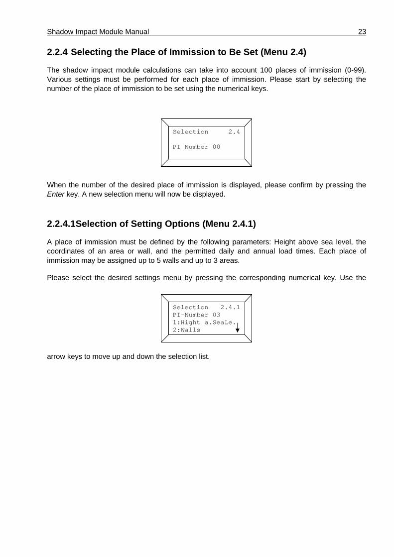
2.2.4 Selecting the Place of Immission to Be Set (Menu 2.4)
The shadow impact module calculations can take into account 100 places of immission (0-99). Various settings must be performed for each place of immission. Please start by selecting the number of the place of immission to be set using the numerical keys.
When the number of the desired place of immission is displayed, please confirm by pressing the Enter key. A new selection menu will now be displayed.
2.2.4.1 Selection of Setting Options (Menu 2.4.1)
A place of immission must be defined by the following parameters: Height above sea level, the coordinates of an area or wall, and the permitted daily and annual load times. Each place of immission may be assigned up to 5 walls and up to 3 areas.
Please select the desired settings menu by pressing the corresponding numerical key. Use the
arrow keys to move up and down the selection list.
Selection 2.4
PI Number 00
Selection 2.4.1 PI-Number 03 1:Hight a.SeaLe. 2:Walls

24 User Manual, Version 3.0
2.2.4.1.1 Entering the Height a. Sea Level for a Place of Immission (Menu 2.4.1.1)
Please enter the place of immission's height above sea level in meters using the numerical keys. Start by entering an algebraic sign. If you skip this entry, the algebraic sign will remain positive.
Confirm your entry by pressing the Enter key. You will automatically return to the selection menu for further settings regarding the place of immission selected.
2.2.4.1.2 Entering the Wall of a Place of Immission (Menu 2.4.1.2)
A wall is defined by its corner coordinates, height and orientation.
Start by using the arrow keys to select the number of the wall (wall 0 – wall 4) for which you plan to enter the corresponding parameters.
Please confirm the selected wall number by pressing the Enter key.
First you must enter the two pairs of corner coordinates (x and y or easting and northing) of the wall in 7-digit Gauss-Krueger format. Now enter the first pair of coordinates for the wall using the numerical keys. Use the arrow keys to navigate through the items.
In the 3rd line, enter the x coordinate (easting); in the 4th line, enter the y coordinate (northing). The
Entry 2.4.1.1PI-Number 03Height above Sea Level: 0000m
Selection 2.4.1.2 Wall No.: 0
Entry 2.4.1.2Wall Coordinatesx(0,0): 0000000 y(0,0): 0000000
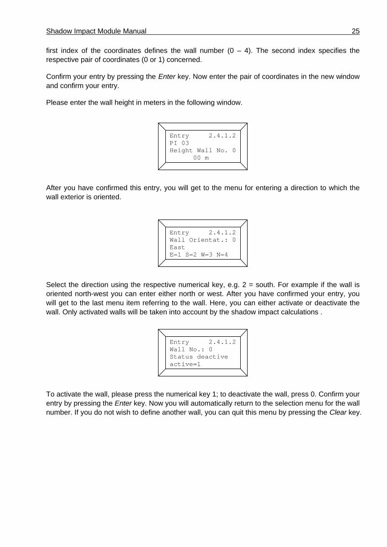
Shadow Impact Module Manual 25
first index of the coordinates defines the wall number (0 – 4). The second index specifies the respective pair of coordinates (0 or 1) concerned.
Confirm your entry by pressing the Enter key. Now enter the pair of coordinates in the new window and confirm your entry.
Please enter the wall height in meters in the following window.
After you have confirmed this entry, you will get to the menu for entering a direction to which the wall exterior is oriented.
Select the direction using the respective numerical key, e.g. 2 = south. For example if the wall is oriented north-west you can enter either north or west. After you have confirmed your entry, you will get to the last menu item referring to the wall. Here, you can either activate or deactivate the wall. Only activated walls will be taken into account by the shadow impact calculations .
To activate the wall, please press the numerical key 1; to deactivate the wall, press 0. Confirm your entry by pressing the Enter key. Now you will automatically return to the selection menu for the wall number. If you do not wish to define another wall, you can quit this menu by pressing the Clear key.
Entry 2.4.1.2PI 03Height Wall No. 0 00 m
Entry 2.4.1.2Wall Orientat.: 0 EastE=1 S=2 W=3 N=4
Entry 2.4.1.2Wall No.: 0 Status deactiveactive=1

26 User Manual, Version 3.0
2.2.4.1.3 Entering the Areas of a Place of Immission (Menu 2.4.1.3)
Start by using the arrow keys to select the number of the area (area 0 – area 2) for which you plan to enter the corresponding parameters.
Please confirm the selected area number by pressing the Enter key.
An area is defined by its four pairs of corner coordinates. Just like walls, areas are defined applying the Gauss-Krueger format.
Now enter the first pair of coordinates for the area using the numerical keys. Use the arrow keys to navigate through the items.
In the 3rd line, enter the x coordinate (easting); in the 4th line, enter the y coordinate (northing). The first index of the coordinates defines the area number. The second index specifies the respective pair of coordinates (0 or 3) concerned.
Confirm your entry by pressing the Enter key. Now enter the next pair of coordinates in the new window and confirm your entry. For each area, you must enter a total of four pairs of coordinates. After you have confirmed the last pair of coordinates, a menu for activating or deactivating the area will be displayed. Only activated areas will be taken into account by the shadow impact calculations.
To activate the area, please press the numerical key 1; to deactivate the area, press 0. Confirm your entry by pressing the Enter key. Now you will automatically return to the selection menu for the area number. If you do not wish to define another area, you can quit this menu by pressing the Clear key.
Selection 2.4.1.3 Area No.: 0
Entry 2.4.1.3Area Coordinatesx(0,0): 0000000 y(0,0): 0000000
Entry 2.4.1.3Area No.: 0 Status deactiveactive=1

Shadow Impact Module Manual 27
2.2.4.1.4 Entering the Permitted Load Times (Menu 2.4.1.4)
The places of immission must be assigned different maximum permitted daily and annual load times according to the limit values specified by the authorities. Use this menu item to enter the corresponding times. The annual load is preset to 480 min (=8 h); the daily load is preset to 30 min.
Use the numerical keys to enter the permitted limit value for the annual load in minutes in the 3rd line. In the 4th line, enter the permitted limit value for the daily load time in minutes. Use the arrow keys to navigate through the items. Please confirm your entry by pressing the Enter key.
2.2.4.1.5 Setting the Annual Counter (Menu 2.4.1.5)
Here you can enter how many hours the respective place of immission has been exposed to shadow impact so far during the current year. This setting may be required in cases where the shadow impact module is installed e.g. in the middle of the year if the place of immission has been exposed to shadow impact for several hours prior to the installation.
The counter is set using the numerical keys. Use the arrow keys to navigate through the entry positions. Please confirm your entry by pressing the Enter key.
Entry 2.4.1.4Load timesMinutes/a : 0480 Minutes/d : 0030
Entry 2.4.1.5 Setting Annual Counter 0000 min

28 User Manual, Version 3.0
2.2.4.1.6 Setting the Beginning of the Year (Menu 2.4.1.6)
Here you can select the first day of the annual period to be considered on which the annual counters will be reset to zero. The beginning of the year is preset to 01.09. The ideal date to choose depends on the seasons during which the place of immission can be shadowed. As a general rule, the beginning of the year should be set to the beginning of the strong wind period.
Enter the desired date using the numerical keys. Confirm your entry by pressing the Enter key.
Enzry 2.4.1.6Begin. Of YearDay : 01 Month: 09
Shadow Impact Module Manual 29
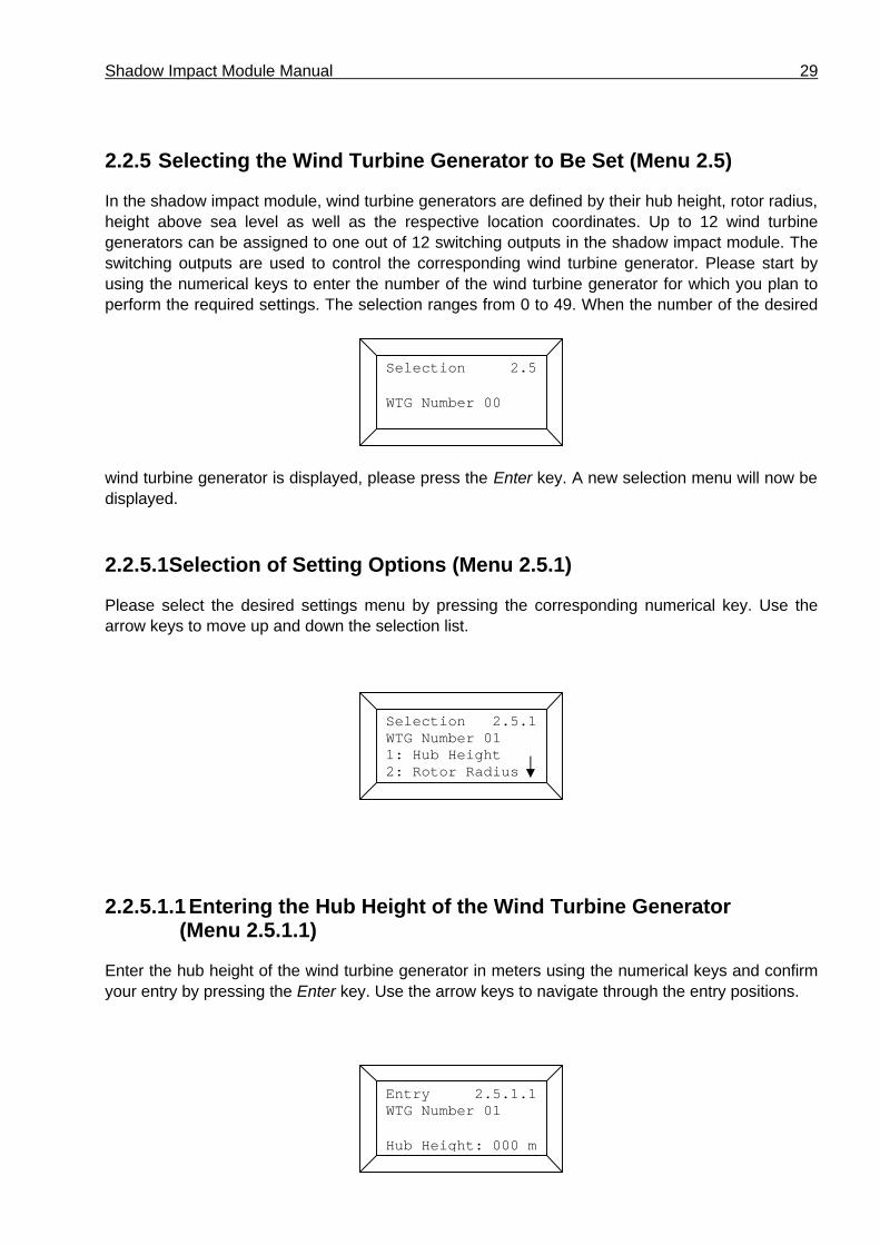
2.2.5 Selecting the Wind Turbine Generator to Be Set (Menu 2.5)
In the shadow impact module, wind turbine generators are defined by their hub height, rotor radius, height above sea level as well as the respective location coordinates. Up to 12 wind turbine generators can be assigned to one out of 12 switching outputs in the shadow impact module. The switching outputs are used to control the corresponding wind turbine generator. Please start by using the numerical keys to enter the number of the wind turbine generator for which you plan to perform the required settings. The selection ranges from 0 to 49. When the number of the desired
wind turbine generator is displayed, please press the Enter key. A new selection menu will now be displayed.
2.2.5.1 Selection of Setting Options (Menu 2.5.1)
Please select the desired settings menu by pressing the corresponding numerical key. Use the arrow keys to move up and down the selection list.
2.2.5.1.1 Entering the Hub Height of the Wind Turbine Generator (Menu 2.5.1.1)
Enter the hub height of the wind turbine generator in meters using the numerical keys and confirm your entry by pressing the Enter key. Use the arrow keys to navigate through the entry positions.
Selection 2.5
WTG Number 00
Selection 2.5.1 WTG Number 01 1: Hub Height 2: Rotor Radius
Entry 2.5.1.1WTG Number 01
Hub Height: 000 m

30 User Manual, Version 3.0
2.2.5.1.2 Entering the Rotor Radius (Menu 2.5.1.2)
Enter the rotor radius of the wind turbine generator in meters using the numerical keys and confirm your entry by pressing the Enter key. Use the arrow keys to navigate through the entry positions.
2.2.5.1.3 Entering the Altitude of the Wind Turbine Generator (Menu 2.5.1.3)
Please enter the height above seal level of the wind turbine generator in meters using the numerical keys. Start by entering an algebraic sign. If you skip this entry, the algebraic sign will remain positive.
Confirm your entry by pressing the Enter key. Use the arrow keys to navigate through the entry positions.
2.2.5.1.4 Entering the Coordinates of the Wind Turbine Generator (Menu 2.5.1.4)
The location coordinates of the wind turbine generator are entered in 7-digit Gauss-Krueger format. In the 3rd line, enter the x coordinate (easting); in the 4th line, enter the y coordinate (northing). The index of the coordinates indicates the number of the wind turbine generator.
Enter the coordinates of the wind turbine generator using the numerical keys and confirm your entry by pressing the Enter key. Use the arrow keys to navigate through the entry positions.
Entry 2.5.1.2WTG Number 01
RotorRadius:000m
Entry 2.5.1.3WTG Number 01Height above Sea Level: 0005 m
Entry 2.5.1.4WTG Coordinatesx(01): 3502966 y(01): 6401078

Shadow Impact Module Manual 31
2.2.5.1.5 Control (Menu 2.5.1.5)
The shadow impact module can be provided with 1 to 12 switching outputs Each of the existing switching outputs may be assigned to one of the 50 wind turbine generators. By default, all of the wind turbine generators are non-switchable. This state applies to all those wind turbine generators which do cause shadow impact in a place of immission but are not monitored by a shadow impact module.
To change the mode of the wind turbine generator selected to "switchable", please press the F1 key. For a short while, the following will be displayed:
Then, the switching output assigned to the wind turbine generator will be displayed. The switching output is preset to 99. The number of physically existing switching outputs ranges from 0 to 11 (maximum number). Therefore, a shadow impact module for switching e.g. five wind turbine generators will have the physical switching outputs 0 to 4. If you select a switching output with a number exceeding the number of physical existing switching outputs for a wind turbine generator, this wind turbine generator will be regarded as switchable; however, the shadow impact module will not be able to shut down this wind turbine generator. This state applies to all those wind turbine generators monitored by a different shadow impact module running in parallel.
Set the desired switching output using the numerical keys and confirm your entry by pressing the Enter key. Please double-check your settings in the following display.
Entry 2.5.1.5 Control WTG 04 not Switchable Change F1
WTG Switchable
Entry 2.5.1.5 Control WTG 04 Select Output 99
32 User Manual, Version 3.0
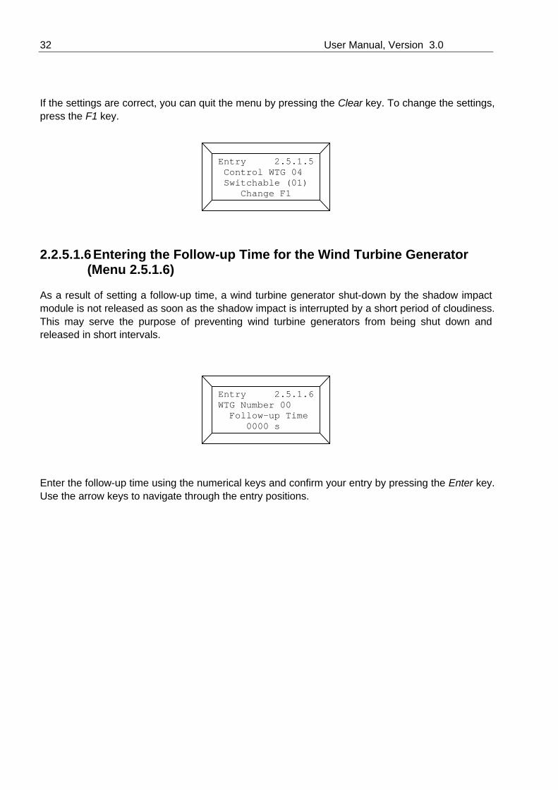
If the settings are correct, you can quit the menu by pressing the Clear key. To change the settings, press the F1 key.
2.2.5.1.6 Entering the Follow-up Time for the Wind Turbine Generator (Menu 2.5.1.6)
As a result of setting a follow-up time, a wind turbine generator shut-down by the shadow impact module is not released as soon as the shadow impact is interrupted by a short period of cloudiness. This may serve the purpose of preventing wind turbine generators from being shut down and released in short intervals.
Enter the follow-up time using the numerical keys and confirm your entry by pressing the Enter key. Use the arrow keys to navigate through the entry positions.
Entry 2.5.1.5 Control WTG 04 Switchable (01) Change F1
Entry 2.5.1.6 WTG Number 00 Follow-up Time 0000 s

Shadow Impact Module Manual 33
2.2.5.1.7 Sound Option Selection (Menu 2.5.1.7)
This menu item and its sub items are relevant only if the shadow impact module is provided with the sound option.
The sound option enables shutting down wind turbine generators for predefined periods of time. The shut-down may be set to be performed on specific days or on a regular basis (specific days of the week).
Select either shut-down by date or shut-down by day of the week by pressing the respective numerical key.
2.2.5.1.7.1 Shut-Down by Date (Menu 2.5.1.7.1)
You may enter 20 different dates on which the wind turbine generator is to be shut down. Start by selecting a date number ranging from 0 to 19 using the numerical keys. Confirm your entry by pressing the Enter key.
Then enter the date on which you would like the wind turbine generator to be shut down. Confirm your entry by pressing the Enter key.
Selec. 2.5.1.7.1
Number of Date 00
Selection 2.5.1.7 Sound WTG 00 1 Date 2 Day of Week
Selec. 2.5.1.7.1 Day : 24 Month : 12 Year : 03

34 User Manual, Version 3.0
Now please enter the shut-down time. Again, confirm your entry by pressing the Enter key.
Finally, enter the shut-down period in minutes.
Confirm your entry by pressing the Enter key. The shut-down date is now active.
2.2.5.1.7.2 Shut-Down by Day of the Week (Menu 2.5.1.7.2)
For each day of the week, you may define a shut-down time. After the shut-down period set has elapsed, the wind turbine generator will be released.
First, select the day of the week using the numerical keys and confirm your selection by pressing the Enter key. (1 = Monday, 2 = Tuesday etc.)
Selec. 2.5.1.7.2
Day of Week 1
Entry 2.5.1.7.1 Date : 24.12.03 Hour off : 22 Minute off : 00
Entry 2.5.1.7.1 Date: 24.12.03 Shut Down Period 0480 min
Shadow Impact Module Manual 35
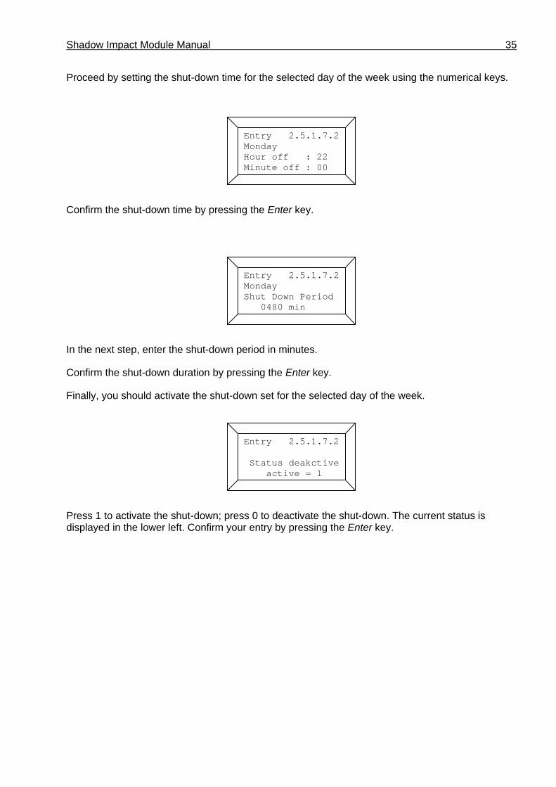
Proceed by setting the shut-down time for the selected day of the week using the numerical keys.
Confirm the shut-down time by pressing the Enter key.
In the next step, enter the shut-down period in minutes.
Confirm the shut-down duration by pressing the Enter key.
Finally, you should activate the shut-down set for the selected day of the week.
Press 1 to activate the shut-down; press 0 to deactivate the shut-down. The current status is displayed in the lower left. Confirm your entry by pressing the Enter key.
Entry 2.5.1.7.2 Monday Hour off : 22 Minute off : 00
Entry 2.5.1.7.2 Monday Shut Down Period 0480 min
Entry 2.5.1.7.2 Status deakctive active = 1

36 User Manual, Version 3.0
2.2.6 Combinations (Menu 2.6)
In order for the shadow impact caused by a wind turbine generator to be related to a place of immission, the wind turbine generator and the place of immission must be combined with each other. After the places of immission and the wind turbine generators have been entered, these are not automatically combined with each other. Combinations must be generated in Menu 2.6.1.
2.2.6.1 Generating the Combinations (Menu 2.6.1.1)
Upon selection of this menu item, all the places of immission are combined with all wind turbine generators. All the combinations generated during this process are assigned the active status (S=1). For a list of combinations, please refer to Menu 2.6.2.
2.2.6.2 Setting the Status of the Combinations (Menu 2.6.2)
After the combinations have been generated, they will be in active status (S=1) Therefore, the shadow impact module will assume that each wind turbine generator may cause shadow impact in each place of immission. However, if there is a visibility obstacle between a wind turbine generator
and a place of immission, real shadow impact is not possible in this place of immission. Yet, the shadow impact module will determine theoretical shadow impact. To avoid this, the respective combinations need to be deactivated. Menu 2.6.2. displays a list of combinations. You can use the up and down arrow keys to move up and down the list. The right and left arrow keys are used to move to the next 30 combinations in the list. A list item includes the consecutive number of the
Action 2.6.1 CombinationsWill be generated
Selection 2.6 Combinations 1:Generate 2:Set Status
Action 2.6.2 C000W01P001S1 C001W01P002S1 C002W02P001S1 i

Shadow Impact Module Manual 37
combination (Cxxx), the number of the wind turbine generator (Wxx), the number of the place of immission (Pxxx) and the status of the combination (Sx). The list is sorted first by the numbers of the wind turbine generators, then by the numbers of the places of immission. To change the status of a combination, the respective list item must be in the first line of the portion of the list displayed. To deactivate a combination, please press 0; to activate a combination, press 1. Your settings will not be applied, unless you confirm by pressing the Enter key.
2.2.7 Selecting the Light Sensor Settings (Menu 2.7)
Up to four light sensors may be connected to the shadow impact module as required. Each light sensor can be adopted to the ambient conditions by adjusting the sensitivity. In addition, you can set a hysteresis determining how fast the shadow impact module responses to a change from sunshine to cloudy weather or vice versa.
Please select the desired entry menu pressing the respective numerical key.
2.2.7.1 Entering the Number of Light Sensors (Menu 2.7.1.)
Use this menu to enter the number of light sensors connected to the shadow impact module. This parameter is preset to 1.
Use the arrow keys to select the number of light sensors, and confirm your selection by pressing the Enter key.
Selection 2.71: Number2: Adjustment3: Hysteresis
Entry 2.7.1 No. Of Sensors 1

38 User Manual, Version 3.0
2.2.7.2 Adjusting the Sensors (Menu 2.7.2)
This menu allows for adjusting the light sensor sensitivity according to the ambient light conditions. The light sensitivity is preset to 1. Usually, you can retain this value. Increasing this value will increase the sensitivity of the light sensor. In case adjusting the sensitivity should be necessary, modify the value only slightly and observe the behaviour of the shadow impact module afterwards. Changing the sensitivity from 1 to 2 will cause the shadow impact module to consider shadow impact effects possible at half the direct sunlight portion.
Use the numerical arrow keys to select the number of the sensor for which you wish to change the sensitivity. Confirm your entry by pressing the Enter key. Now you can revise the sensitivity using
the numerical keys. Confirm your entry by pressing the Enter key. To quit the menu, press the Clear key.
2.2.7.3 Entering a Hysteresis (Menu 2.7.3)
Only after the period defined by the hysteresis has elapsed, a change from "shadow impact" to "no shadow impact" will be taken into account. The hysteresis is preset to 60 seconds. To prevent the wind turbine generators from being shut down and released in short intervals due to unsettled weather conditions, the hysteresis should not be set too low.
Enter the hysteresis using the numerical keys and confirm your entry by pressing the Enter key. Use the arrow keys to navigate through the entry positions.
Entry 2.7.2 Sensitivity Sensor-No.: 0 01,000
Entry 2.7.3
Hysteresis 060 s
Shadow Impact Module Manual 39
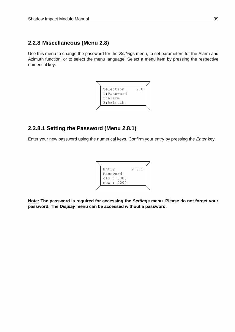
2.2.8 Miscellaneous (Menu 2.8)
Use this menu to change the password for the Settings menu, to set parameters for the Alarm and Azimuth function, or to select the menu language. Select a menu item by pressing the respective numerical key.
2.2.8.1 Setting the Password (Menu 2.8.1)
Enter your new password using the numerical keys. Confirm your entry by pressing the Enter key.
Note: The password is required for accessing the Settings menu. Please do not forget your password. The Display menu can be accessed without a password.
Selection 2.81:Password2:Alarm3:Azimuth
Entry 2.8.1Passwordold : 0000 new : 0000

40 User Manual, Version 3.0
2.2.8.2 Parameters for the Alarm Function (Menu 2.8.2)
From this menu, you can navigate to the displays for setting the Alarm function parameters. Just press the desired numerical key.
2.2.8.2.1 Entering the Alarm Output (Menu 2.8.2.1)
One shadow impact module can have up to 12 switching outputs (00 – 11). The switching output will drive the respective relay (K00 – K11) on the top hat rail. Use the numerical keys to select the switching output, and confirm your entry by pressing the Enter key.
2.2.8.2.2 Clearing an Alarm (Menu 2.8.2.2)
Use this menu to clear a pending alarm.
Selection 2.8.21:Output2:Alarm Reset3:LimitValue RCC
Action 2.8.2.2
Alarm deleted Alarm Status = 0
Entry 2.8.2.1 Alarm Output: 11
Shadow Impact Module Manual 41
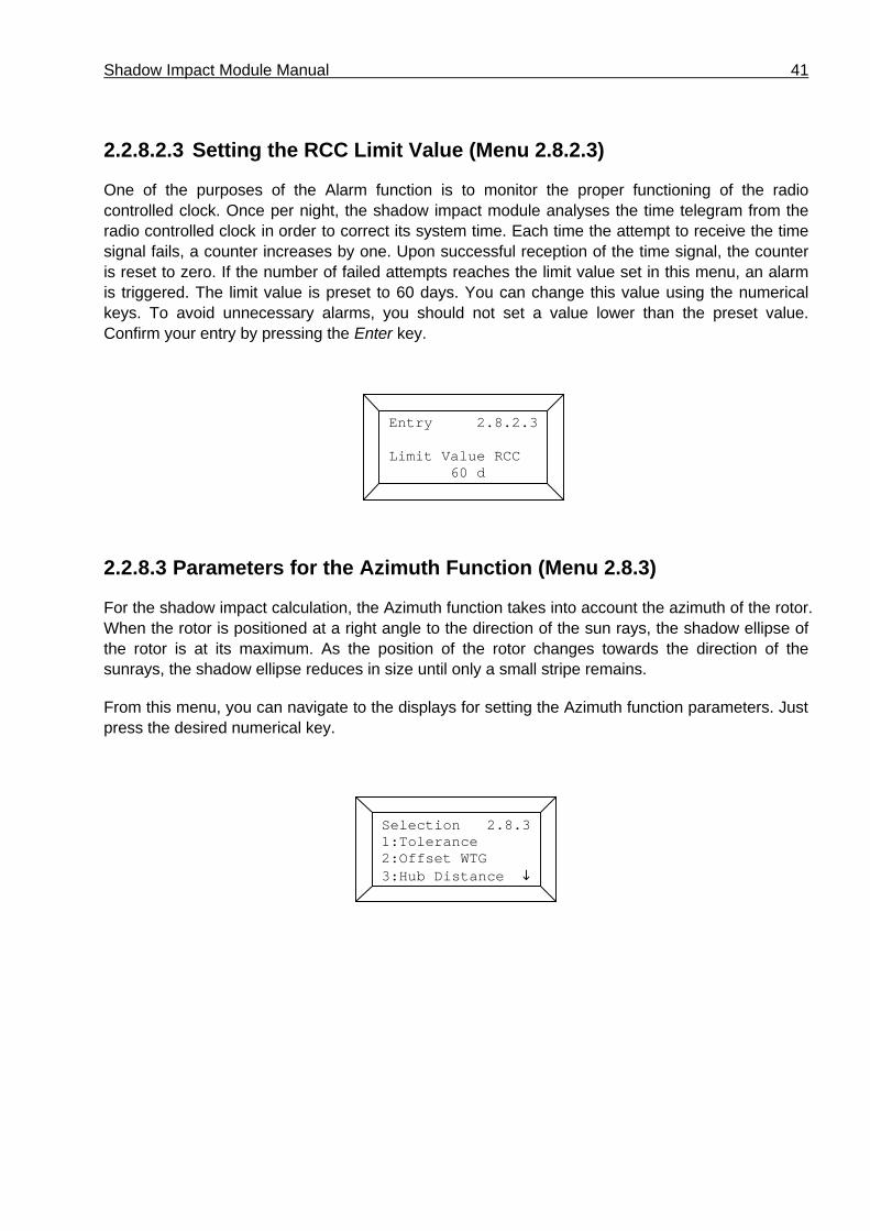
2.2.8.2.3 Setting the RCC Limit Value (Menu 2.8.2.3)
One of the purposes of the Alarm function is to monitor the proper functioning of the radio controlled clock. Once per night, the shadow impact module analyses the time telegram from the radio controlled clock in order to correct its system time. Each time the attempt to receive the time signal fails, a counter increases by one. Upon successful reception of the time signal, the counter is reset to zero. If the number of failed attempts reaches the limit value set in this menu, an alarm is triggered. The limit value is preset to 60 days. You can change this value using the numerical keys. To avoid unnecessary alarms, you should not set a value lower than the preset value. Confirm your entry by pressing the Enter key.
2.2.8.3 Parameters for the Azimuth Function (Menu 2.8.3)
For the shadow impact calculation, the Azimuth function takes into account the azimuth of the rotor. When the rotor is positioned at a right angle to the direction of the sun rays, the shadow ellipse of the rotor is at its maximum. As the position of the rotor changes towards the direction of the sunrays, the shadow ellipse reduces in size until only a small stripe remains.
From this menu, you can navigate to the displays for setting the Azimuth function parameters. Just press the desired numerical key.
Selection 2.8.31:Tolerance2:Offset WTG3:Hub Distance i
Entry 2.8.2.3 Limit Value RCC 60 d

42 User Manual, Version 3.0
2.2.8.3.1 Setting the Azimuth Tolerance (Menu 2.8.3.1)
In order to take into account a potential inaccurateness of the azimuth signal provided by the wind turbine generator, you can enter an azimuth tolerance. The azimuth tolerance is entered in degrees. This valued is added to the angle between the direction of the sunrays and the position of
the rotor. The azimuth tolerance is preset to 5°. The higher the azimuth tolerance you set, the less effective the Azimuth function. However, if the value selected for the azimuth tolerance is too low, an inaccurate azimuth signal may cause the size of the rotor shadow to be underrated.
Enter the azimuth tolerance using the numerical keys and confirm your entry by pressing the Enter key.
2.2.8.3.2 Setting the Azimuth Offset (Menu 2.8.3.2)
This menu can be used to compensate for a potential offset of the azimuth signal from the wind turbine generator. The offset, which is always positive, is subtracted from the azimuth. Example: if the azimuth signal differs from the actual azimuth by –10°, the azimuth offset must be 350°. The azimuth offset is preset to 0°.
Enter the azimuth offset using the numerical keys and confirm your entry by pressing the Enter key.
Entry 2.8.3.2 Offset Azimuth 000 Degree
Entry 2.8.3.1 ToleranceAzimuth 05 Degree

Shadow Impact Module Manual 43
2.2.8.3.3 Entering the Hub Distance (Menu 2.8.3.3)
Use this menu to enter the distance of the rotor hub from the centre of the tower in meters. This input is required for the calculation of the position of the rotor which changes due to the rotation of the nacelle.
Enter the hub distance using the numerical keys and confirm your entry by pressing the Enter key.
2.2.8.3.4 Entering the Measuring Cycle (Menu 2.8.3.4)
Use this menu to enter the time period between two measurements of the rotor azimuth in minutes.
Enter the measuring cycle using the numerical keys and confirm your entry by pressing the Enter key.
Entry 2.8.3.3
Hub Distance 03 m
Entry 2.8.3.4
Measure Cycle 15 min

44 User Manual, Version 3.0
2.2.8.3.5 Entering the Number of Measurements (Menu 2.8.3.5)
Depending on the method used to determine the azimuth of the rotor, it may be necessary to average the azimuth signal from the wind turbine generator. Use this menu to enter the number of measurements to be averaged later on.
Enter the number of measurements using the numerical keys and confirm your entry by pressing the Enter key.
2.2.8.4 Selecting the Menu Language (Menu 2.8.4)
Use this menu to select the menu language by pressing the respective numerical key. The Language function is optional and therefore not available in every shadow impact module.
Action 2.8.4Language1:German2:English
Entry 2.8.3.5 Number of Measurements 05

Shadow Impact Module Manual 45
2.2.9 Control Check (Menu 2.9)
Within this menu you can shut down and release the wind turbine generators in order to check the connections between the controls of the wind turbine generators and the shadow impact module.
Start by using the arrow keys to select the wind turbine generator you wish to start/shut down. Confirm your entry by pressing the Enter key. The following will be displayed:
The current status of the wind turbine generator selected is displayed in the 2nd line. Status 1 means that the wind turbine generator is running, status 0 means that the wind turbine generator has been shut down by the shadow impact module.
To shut down the wind turbine generator, please press the F1 key, to start, press the F2 key. To quit the menu, press the Clear key.
Selection 2.9 Control Test WTG Number 03
Action 2.9.1Status WTG 03: 1 WTG Stopp = F1WTG Start = F2
46 User Manual, Version 3.0
3 Maintenance of the Shadow Impact Module
The shadow impact module is maintenance-free to a great extent. However, the light sensors must be checked for dirt and cleaned as necessary on a regular basis.
Also, the proper functioning of the RCC module should be checked every 4 months.
After commissioning the shadow impact module, you should check the shut-down times for plausibility in order to exclude errors in the shadow impact module configuration.
4 Technical Documentation
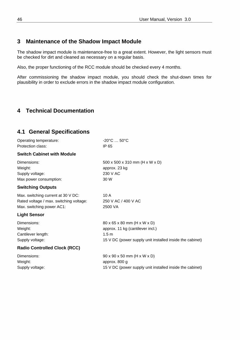
4.1 General Specifications Operating temperature: -20°C … 50°CProtection class: IP 65
Switch Cabinet with Module
Dimensions: 500 x 500 x 310 mm (H x W x D)Weight: approx. 23 kgSupply voltage: 230 V ACMax power consumption: 30 W
Switching Outputs
Max. switching current at 30 V DC: 10 ARated voltage / max. switching voltage: 250 V AC / 400 V ACMax. switching power AC1: 2500 VA
Light Sensor
Dimensions: 80 x 65 x 80 mm (H x W x D)Weight: approx. 11 kg (cantilever incl.)Cantilever length: 1.5 mSupply voltage: 15 V DC (power supply unit installed inside the cabinet)
Radio Controlled Clock (RCC)
Dimensions: 90 x 90 x 50 mm (H x W x D)Weight: approx. 800 gSupply voltage: 15 V DC (power supply unit installed inside the cabinet)
Shadow Impact Module Manual 47
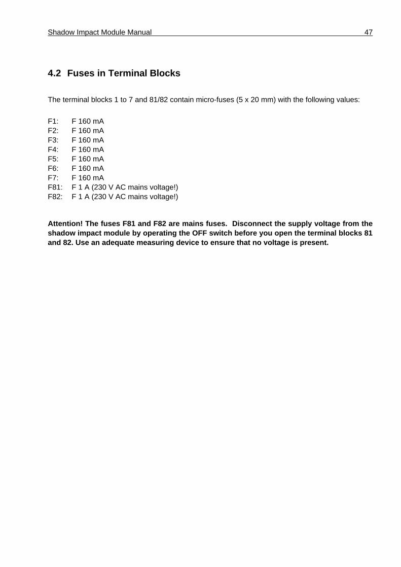
4.2 Fuses in Terminal Blocks
The terminal blocks 1 to 7 and 81/82 contain micro-fuses (5 x 20 mm) with the following values:
F1: F 160 mAF2: F 160 mAF3: F 160 mAF4: F 160 mAF5: F 160 mAF6: F 160 mAF7: F 160 mAF81: F 1 A (230 V AC mains voltage!)F82: F 1 A (230 V AC mains voltage!)
Attention! The fuses F81 and F82 are mains fuses. Disconnect the supply voltage from the shadow impact module by operating the OFF switch before you open the terminal blocks 81 and 82. Use an adequate measuring device to ensure that no voltage is present.

48 User Manual, Version 3.0
4.3 Shadow Impact Module Vers. 3.0 Terminal Connections for 1 WTG
SWM 3-0 Klemmenbelegung 1 Ausgang eng
N o rthTec G m bH
Datum / Zeichnungs-Version:Bearbeiter:
Pfad:
17.11.03 / Vers.1.0M. HartmundF:\Schattenwurfmodul/Handbücher/Version 3
Titel:
Shadow Impact Module Version 3.0 for 1 WTG
WTG Control
83 84 80 1 2 3 4 5 6 7 12 11
K 00
14L N PE
230 V AC
24 V DC
Backplane
F80 F81 F1 F2 F3 F4 F5 F6 F7
RC
C S
igna
l
15V
DC
0V D
C
Sen
sor S
igna
l 1
Sen
sor S
igna
l 2
Sen
sor S
igna
l 3
Sen
sor S
igna
l 4
Mains Supply Sensor and RCC Connection

Shadow Impact Module Manual 49
4.4 Shadow Impact Module Vers. 3.0 Terminal Connections for 6 WTGs
SWM 3-0 Klemmenbelegung 6 Ausgänge eng
N o r t h Tec G m bH
Datum / Zeichnungs-Version:Bearbeiter:
Pfad:
19.11.03 / Vers.1.0M. HartmundF:\Schattenwurfmodul/Handbücher/Version 3
Titel:
Shadow Impact Module Version 3.0 for 6 WTG
WTG Control
83 84 80 1 2 3 4 5 6 7 12 11
K 00
14L N PE
230 V AC
24 V DC
Backplane
F80 F81 F1 F2 F3 F4 F5 F6 F7
RC
C S
igna
l
15V
DC
0V D
C
Sen
sor S
igna
l 1
Sen
sor S
igna
l 2
Sen
sor S
igna
l 3
Sen
sor S
igna
l 4
Mains Supply Sensor and RCC Connection
230 V AC
24 V DC
12 11
K 01
14 12 11
K 02
14 12 11
K 03
14 12 11
K 05
1412 11
K 04
14
Relais
NT 1 NT 2
100
24V
DC
from
NT
2
0V D
C fr
om N
T 2
24V
50 User Manual, Version 3.0
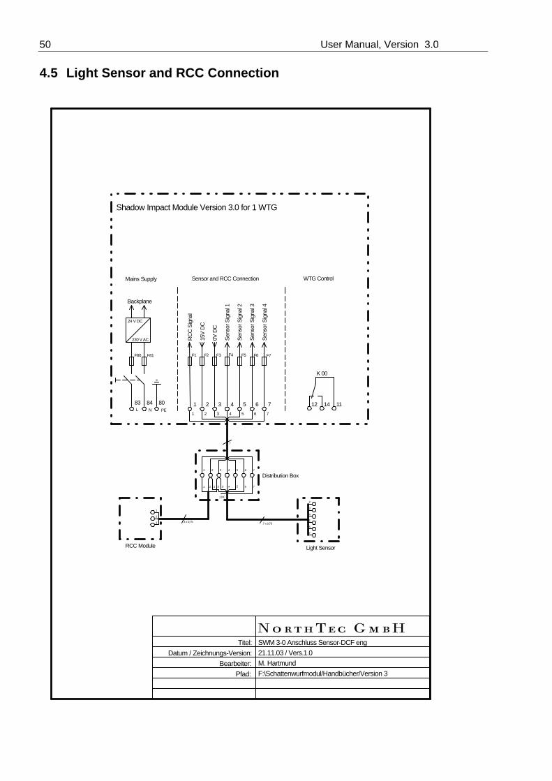
4.5 Light Sensor and RCC Connection
SWM 3-0 Anschluss Sensor-DCF eng
N o r t h Tec G m bH
Datum / Zeichnungs-Version:Bearbeiter:
Pfad:
21.11.03 / Vers.1.0M. HartmundF:\Schattenwurfmodul/Handbücher/Version 3
Titel:
Shadow Impact Module Version 3.0 for 1 WTG
WTG Control
83 84 80 1 2 3 4 5 6 7 12 11
K 00
14L N PE
230 V AC
24 V DC
Backplane
F80 F81 F1 F2 F3 F4 F5 F6 F7
RC
C S
igna
l
15V
DC
0V D
C
Sen
sor S
igna
l 1
Sen
sor S
igna
l 2
Sen
sor S
igna
l 3
Sen
sor S
igna
l 4
Mains Supply Sensor and RCC Connection
1 2 3 4 5 6 73
1 2 3 4 5 6 7
2
1 NC
1 2 3 4 5 6 7
1
2
3
2
3
4
5
6
7
7 x 0,753 x 0,75
7
RCC Module Light Sensor
Distribution Box

Shadow Impact Module Manual 51
5 Appendix
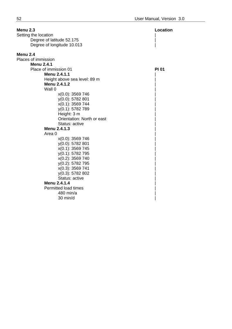
5.1 Configuration Example The following is the description of a shadow impact module configuration using an example. The shadow impact module is to monitor the shadow impact of two wind turbine generators (WTG 1 and WTG 2) in two places of immission (PI 1 and PI 2). PI 2 is exposed to shadow impact caused by a third wind turbine generator (WTG 3). Since WTG 3 has already been operated for 2 years and does not exceed any limit values by itself, it must be considered as preload. WTG 1 and WTG 2 are located west of the places of immission, WTG 3 is located east of the places of immission.A maximum daily load of 30 minutes and a maximum annual load of 8 hours is allowed in the places of immission.The shadow impact module is installed in WTG 1.The following shadow impact module configuration data must be entered:Location of the shadow impact moduleThe location of the shadow impact module has a degree of latitude of 52.175 ° N and a degree of longitude of 10.013 °E. The numbers to the right of the decimal point must be decimal numbers as opposed to minutes and seconds.PI 1 has one wall which is oriented to WTG 1 and WTG 2. The relevant wall area has the following pairs of corner coordinates: (3569 746 / 5782 801) and (3569 744 / 5782 789). The wall height is 3 meters. The wall exterior is oriented north-west.In front of the wall there is a patio area to be taken into account as well. The patio area has the following four pairs of corner coordinates: (3569 746 / 5782 801), (3569 745 / 5782 795), (3569 740 / 5782 795) and (3569 741 / 5782 802).PI 2 has a wall which is oriented to WTG 1 and WTG 2 as well. The relevant wall area has the following pairs of corner coordinates: (3569 731 / 5782 723) and (3569 729 / 5782 711). The wall height is 5 meters. The wall exterior is oriented north-west. Another house wall is oriented to WTG 3. The relevant wall area has the following pairs of corner coordinates: (3569 752 / 5782 722) and (3569 751 / 5782 719). The wall height is 3 meters. The wall exterior is oriented south-east.The height above sea level of the places of immission is 89 meters.WTG 1 and WTG 2 have a hub height of 85 meters and a rotor radius of 35 meters. The location coordinates of WTG 1 are as follows: (3569 344 / 5782 850). The height above sea level is 92 meters. The location coordinates of WTG 2 are as follows: (3569 214 / 5782 653). The height above sea level is 93 meters. WTG 3 has a hub height of 60 meters and a rotor radius of 27 meters. The location coordinates of WEA 3 are as follows: (3570 093 / 5782 699). The height above sea level is 88 meters.Using the above data, the shadow impact module can be completely configured. The coordinates are specified in Gauss-Krueger format. The first value represents "easting", the second value represents "northing".After these data have been entered, the places of immission need to be combined with the wind turbine generators. Combining is necessary only if the wind turbine generator is actually capable of causing real shadow impact in the corresponding place of immission. Therefore, combining WTG 3 with PI 1 in this example would not make sense.
52 User Manual, Version 3.0
Menu 2.3 LocationSetting the location | Degree of latitude 52.175 | Degree of longitude 10.013 |
Menu 2.4 Places of immission
Menu 2.4.1 Place of immission 01 PI 01
Menu 2.4.1.1 | Height above sea level: 89 m |
Menu 2.4.1.2 | Wall 0 |
x(0.0): 3569 746 | y(0.0): 5782 801 | x(0.1): 3569 744 | y(0.1): 5782 789 | Height: 3 m | Orientation: North or east | Status: active | Menu 2.4.1.3 | Area 0 | x(0.0): 3569 746 | y(0.0): 5782 801 | x(0.1): 3569 745 | y(0.1): 5782 795 | x(0.2): 3569 740 | y(0.2): 5782 795 | x(0.3): 3569 741 | y(0.3): 5782 802 | Status: active | Menu 2.4.1.4 |
Permitted load times | 480 min/a | 30 min/d |

Shadow Impact Module Manual 53
Menu 2.4.1
Place of immission 02 PI 02Menu 2.4.1.1 |
Height above sea level: 89 m | Menu 2.4.1.2 | Wall 0 | x(0.0): 3569 731 | y(0.0): 5782 723 | x(0.1): 3569 729 | y(0.1): 5782 711 | Height: 5 m | Orientation: North or east | Status: active | Menu 2.4.1.2 | Wall 1 | x(0.0): 3569 752 | y(0.0): 5782 722 | x(0.1): 3569 751 | y(0.1): 5782 719 | Height: 3 m | Orientation: South or east | Status: active | Menu 2.4.1.4 |
Permitted load times | 480 min/a | 30 min/d | Menu 2.5 Wind turbine generators
Menu 2.5.1 WTG 01 WTG 01
Menu 2.5.1.1 | Hub height: 85 m |
Menu 2.5.1.2 | Rotor radius: 35 m | Menu 2.5.1.3 | Height above sea level: 92 m | Menu 2.5.1.4 | Location coordinates | X(01): 3569 344 | Y(01): 5782 850 | Menu 2.5.1.5 | WTG switchable | Switching output 00 |
54 User Manual, Version 3.0
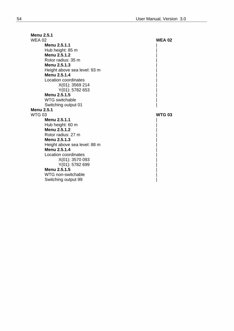
Menu 2.5.1
WEA 02 WEA 02Menu 2.5.1.1 | Hub height: 85 m |
Menu 2.5.1.2 | Rotor radius: 35 m | Menu 2.5.1.3 | Height above sea level: 93 m | Menu 2.5.1.4 | Location coordinates | X(01): 3569 214 | Y(01): 5782 653 | Menu 2.5.1.5 | WTG switchable | Switching output 01 | Menu 2.5.1
WTG 03 WTG 03Menu 2.5.1.1 |
Hub height: 60 m | Menu 2.5.1.2 | Rotor radius: 27 m | Menu 2.5.1.3 | Height above sea level: 88 m | Menu 2.5.1.4 | Location coordinates | X(01): 3570 093 | Y(01): 5782 699 | Menu 2.5.1.5 | WTG non-switchable | Switching output 99 |
Shadow Impact Module Manual 55
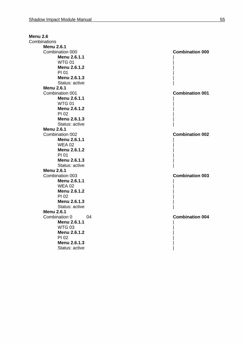
Menu 2.6 Combinations
Menu 2.6.1 Combination 000 Combination 000
Menu 2.6.1.1 | WTG 01 |
Menu 2.6.1.2 | PI 01 | Menu 2.6.1.3 | Status: active | Menu 2.6.1
Combination 001 Combination 001Menu 2.6.1.1 |
WTG 01 | Menu 2.6.1.2 | PI 02 | Menu 2.6.1.3 | Status: active | Menu 2.6.1
Combination 002 Combination 002Menu 2.6.1.1 |
WEA 02 | Menu 2.6.1.2 | PI 01 | Menu 2.6.1.3 | Status: active | Menu 2.6.1
Combination 003 Combination 003Menu 2.6.1.1 |
WEA 02 | Menu 2.6.1.2 | PI 02 | Menu 2.6.1.3 | Status: active | Menu 2.6.1
Combination 0 04 Combination 004Menu 2.6.1.1 |
WTG 03 | Menu 2.6.1.2 | PI 02 | Menu 2.6.1.3 | Status: active |

56 User Manual, Version 3.0
5.2 Example of a Log
Ent
ry
Dat
e
Tim
e
PI
WT
G
Dai
ly C
ount
er
Ann
ual C
ount
er
Win
d D
irect
ion
Win
d S
peed
Pow
er
WT
G S
tatu
s
Eve
nt
1 29.09.2003 8:15:23 2 3 0 347 Shadow Impact2 29.09.2003 8:32:12 2 3 16 363 End of Shadow Impact3 29.09.2003 16:07:12 2 2 16 363 Shadow Impact4 29.09.2003 16:21:15 2 Stop WTG5 29.09.2003 16:44:12 2 2 30 377 End of Shadow Impact6 29.09.2003 16:44:23 2 Start WTG7 29.09.2003 17:01:23 1 1 0 480 Theoretical Shadow Impact8 29.09.2003 17:09:54 1 1 0 480 Shadow Impact9 29.09.2003 17:09:07 1 Stop WTG
10 29.09.2003 17:25:34 1 1 0 480 End of Shadow Impact11 29.09.2003 17:25:42 1 Start WTG
Entry 1: WTG 3 causes real shadow impact in PI 2.Entry 2: The shadow impact in PI 2 caused by WTG 3 has ended as the sun has changed its
position.Entry 3: WTG 2 causes real shadow impact in PI 2.Entry 4: WTG 2 is stopped because the limit value of 30 minutes has been exceeded in PI 2.Entry 5: Since the sun has changed its position, WTG 2 can no longer cause shadow impact
in PI 2.Entry 6: WTG 2 is released.Entry 7: WTG 1 could cause shadow impact in PI 1, provided the direct sun radiation is
strong enough.Entry 8: WTG 1 causes real shadow impact in PI 1.Entry 9: WTG 1 is stopped because the limit value of 8 hours has been exceeded in PI 1.Entry 10: Since the sun has changed its position, WTG 1 can no longer cause shadow impact
in PI 1.Entry 11: WTG 1 is released.