SG28:17 - NASC · to the Timber Frame building or structure (e.g. with kentledge, rakers,...
24
NASC 1 of 24 SG28:17 Safe System of Work for Scaffolding associated with Timber Frame Building Construction February 2017 1. INTRODUCTION This guidance document has been produced as an aid for those associated with timber frame building construction, including clients, main contractors, timber frame engineers, designers, scaffold contractors and users (such as timber frame installers and bricklayers), to enable best practice and compliance with current legislation. When constructing timber framed buildings, there is (initially) no building or structure in place against which the scaffold structure can be tied. The scaffold may be rectangular in shape and typically comprise four flanks connected at 90 degrees around the building slab, but it is still vital that measures to ensure stability are incorporated. Accordingly the initial stability of the scaffold structure must be achieved by means other than ties to the Timber Frame building or structure (e.g. with kentledge, rakers, buttresses, staircase towers), to ensure there is no risk of the scaffold overturning. Note: Scaffolds for timber frame buildings are not presently covered under National Access & Scaffolding Confederation (NASC) Technical Guidance TG20 and therefore require a Scaffold Design. 1 It is vitally important that the work is planned and that a Design and Risk Assessment/Method Statement (RAMS) are produced to eliminate in particular the risk of: • scaffold collapse/ overturning; and • falls from height. Note: It is also vitally important that clients, main contractors and users such as the timber Frame Company/ Bricklaying Company discuss and approve the Safe System of Work to prevent falls as per the Work at Height Regulations 2005 (WAHR) with collective fall prevention – e.g. guardrails – taking precedence over personal (e.g. harnesses). Please see Section 7 for further guidance. 1 The pictorials in this guidance document have been taken from NASC Technical Guidance, TG20:13. Please also note some of the themes/topics detailed in this Safety Guidance are also repeated in SG29 and SG32.
Transcript of SG28:17 - NASC · to the Timber Frame building or structure (e.g. with kentledge, rakers,...

N A S C1 of 24
SG28:17Safe System of Work for Scaffolding associated with Timber Frame Building Construction
February 2017
1. INTRODUCTION
This guidance document has been produced as an aid for those associated with timber frame building construction, including clients, main contractors, timber frame engineers, designers, scaffold contractors and users (such as timber frame installers and bricklayers), to enable best practice and compliance with current legislation.
When constructing timber framed buildings, there is (initially) no building or structure in place against which the scaffold structure can be tied. The scaffold may be rectangular in shape and typically comprise four flanks connected at 90 degrees around the building slab, but it is still vital that measures to ensure stability are incorporated. Accordingly the initial stability of the scaffold structure must be achieved by means other than ties to the Timber Frame building or structure (e.g. with kentledge, rakers, buttresses, staircase towers), to ensure there is no risk of the scaffold overturning.
Note: Scaffolds for timber frame buildings are not presently covered under National Access & Scaffolding Confederation (NASC) Technical Guidance TG20 and therefore require a Scaffold Design.1
It is vitally important that the work is planned and that a Design and Risk Assessment/Method Statement (RAMS) are produced to eliminate in particular the risk of:
• scaffold collapse/ overturning; and
• falls from height.
Note: It is also vitally important that clients, main contractors and users such as the timber Frame Company/ Bricklaying Company discuss and approve the Safe System of Work to prevent falls as per the Work at Height Regulations 2005 (WAHR) with collective fall prevention – e.g. guardrails – taking precedence over personal (e.g. harnesses). Please see Section 7 for further guidance.
1 The pictorials in this guidance document have been taken from NASC Technical Guidance, TG20:13. Please also note some of the themes/topics detailed in this Safety Guidance are also repeated in SG29 and SG32.

N A S C2 of 24
All parties should ensure that they take into account other trades’ requirements – not just the timber frame requirements – but other trades, such as bricklayers, to ensure that the erected scaffold suits all trades (and reduces unnecessary alterations and costs).
Note: With Timber Frame buildings there is often a fire risk. The main contractor should assess the risk and specify if the scaffold will double as an evacuation/escape route (unless the fire plan provides sufficient alternative protected escape routes). The scaffold specification should also take into account if fire retardant sheeting is required (and that any other cladding designed to contain dust or debris must not in itself contribute in any way to the potential for fire to spread).
Please see the reference section for a list of relevant Legislation and Guidance (including HSE Guidance: HSG Fire Safety in Construction).
2. PLANNING (PRE-CONSTRUCTION STAGE)
CDM 2015 requires the client to provide all known relevant information about the site to the main contractor (including assessing suitable ground conditions).
As part of this process, the principal contractor, user and timber frame (TF) engineer must supply any relevant information to the scaffold contractor and the scaffold designer (and/or temporary works designer) at the pre-construction stage to enable items such as tie locations, buttresses, loading bays and access and egress points to be established.
Any sketches supplied by the client (which are sometimes supplied to the client from the timber frame company) should be discussed in full detail prior to design work.
Clients, Principal contractors, Designers, Users, and Scaffold Contractors must take into consideration how the access scaffold will be provided, with, for instance, sufficient space made available for buttressing or any other means of achieving stability (such as staircases, loading bays).
The client should provide details of the structural elements available to facilitate the tying of scaffold. If this is not possible, they should state their assumptions on the construction of the timber-frames when this involves freestanding scaffolds.
Note: Typically this involves a pre-erected scaffold being used to stabilise the building until it becomes self-stabilising. It is also important to note that although the scaffold was originally designed to be free-standing, it is common in timber frame work for it to be subsequently tied to the timber frame structure once the structure is sufficiently rigid to support the scaffold.
Freestanding scaffolds often need additional bracing, buttressing, and kentledge (weighting down) to ensure they do not collapse. They can be particularly vulnerable to wind loading and overloading. Continuous plan bracing is commonly needed to stiffen each flank/elevation of the scaffold and prevent damaging movement.

N A S C3 of 24
Note: All parties should ensure that they take into account other trades requirements – not just the timber frame requirements – but other trades, such as bricklayers, to ensure that the erected scaffold suits all trades (and reduces unnecessary alterations and costs).
At this pre-construction stage, clients, main contractors and users (such as the timber Frame Company/ Bricklaying Company) should discuss and approve:
• The type of scaffold structure;
• The Safe System of Work to prevent falls as per the Work at Height Regulations (with collective fall prevention – e.g. guardrails – taking precedence over personal (e.g. harnesses). Please see Section 7 for further guidance;
• Lift heights – and access arrangements – with consideration given to lift heights being no higher than level with the top of the floor deck and no lower than 600mm below the top of the floor deck (but ideally 300mm from working platform to the fascia/soffit to allow safe access later for roofers).
Sequential Erection Sketches in Appendices (Possible scenario to minimise alterations to scaffolding)There are various possible designs/sketches possible for Timber Frame Structures; please see Appendix A and Appendix B for possible scenarios, which reduces the number of scaffold alterations to reduce costs and improve safety.
Note: Where there are likely to be variations in design – such as only partial erection of scaffolding around a timber structure to allow forklifts to move sections into position – then the scaffold designer should include additional structural requirements to suit the timber frame assembly. This includes instances where the client arranges sections of the timber frame building to be craned into position.
3. DESIGN REQUIREMENTS
As timber frame scaffolding falls outside TG20:13, specific drawings will need to be supplied for each timber frame project, which should include suitable details for the erection of the scaffold being built. In some instances where the building design is repeated, it can be acceptable to use existing generic designs.
Drawings should be issued to the client for approval before work commences. Where the services of a ‘Scaffolding Contractor’ are engaged on a Project, the following conditions will apply and the Scaffolding Contractor must:
• Ensure that the design of any scaffold structure complies with the specification provided by the client, covers all statutory requirements, is safe to use and fit for purpose;
• Ensure that the scaffold design has strength and stability calculations as required by the Work at Height Regulations 2005 and that the design is based on a generally recognised standard configuration (e.g. NASC TG20 for tube and fitting scaffolds or the manufacturer’s instruction manual for system scaffolding) and designed in accordance with the current wind code;
• Agree the tie type, size and location with the client/principal contractor and the TF engineer at the design stage. Ensure that the selection of access and egress takes due consideration as to the frequency and duration of its intended use, including any emergency arrangements;
• Provide a detailed design, including a plan and elevations. Detailed sections should be provided at various intervals where there is a change in the type of construction. The design should be fully annotated giving, where appropriate, the following details as a minimum:
• Type of scaffold (e.g. Tube & Fitting or NASC Approved System);
• Bay sizes;
• Lift heights;
• Number of boarded lifts (including how many main boards and inside boards);
• Access arrangements (e.g. staircases or single lift internal ladders – please see section 6.3);

N A S C4 of 24
• Access arrangements (e.g. phased access permission may be required for upper lifts, which may be out of bounds until the building has reached that level, such as for wall panel installation which is usually carried out from the completed floor below);
• Allowable loads;
• Number of buttresses (sometimes known as loading towers);
• Number of loading bays;
• Bracing positions;
• Tie locations and tie details (including size and type of tie);
• Requirement for inside guardrails;
• Arrangements for future adaptions (including if telescopic transoms or board brackets are to be used);
• Any additional hazards and risks; and
• Kentledge requirements.
Note: the scaffold designer will decide on the type of kentledge used (such as concrete blocks, weights, scaffold tube etc.). Where scaffold tubes are used as kentledge, it is recommended that consideration be given to tying the load down to prevent unauthorised removal and painting kentledge (so as to identify any items removed). Water stored in water butts may be used, but it is likely that stringent control measures will be needed to be put in place to ensure that the water butts are protected from malicious damage and there is no risk of water leakage.
• Take into consideration the requirement and suitability of ground conditions. The Main Contractor to approve prior to works commencing;
• The design should include the most appropriate means of access and egress on to the working platform and there should be sufficient details to enable the scaffold contractor to erect the scaffold and to ensure that the scaffold can be built in accordance with best practice (e.g. SG4 and SG4:You).
The scaffold contractor must ensure that the approved design and all design information is passed on to its scaffold operatives prior to erection. Drawings should give clear and concise instructions relating to any design implications.
During the pre-start briefing of the Method Statement/Risk Assessment (RAMS) by the Supervisor, which includes a review of the design drawings, all operatives must confirm (by a record of their signature), that this information has been received and understood.
4. ExTENDED TRANSOMS, TELESCOPIC TRANSOM UNITS, INSIDE-bOARD bRACkETS
The width of the main platform can be extended by supporting inside boards, between the inner line of standards and the building. Several methods of supporting inside boards are available:
• Extended transoms: the transoms from the main platform can be made long enough to cantilever beyond the inner ledger to provide an extended platform at the working level;
• Telescopic transom units can be used, which allow the width of the inside board platform to be changed, or the platform to be removed, with the progress of the work;
• Inside-board brackets: The inside platform can be supported by inside-board brackets, informally known as ‘hop-up’ or ‘step-down’ brackets, which allow the inner platform to be raised above or lowered below the main platform level.

N A S C5 of 24
Inside board loading When the scaffold platform is constructed with inside boards or inside-board bracket platforms, described in this document, the inside boards or platforms should only be loaded to a maximum of 0.75 kN / m2. This allows for personnel to work on the platforms, with tools and light materials, but it does not allow materials to be stored on the boards.
As with the main platform, only two lifts of inside boards should be in service at any time per elevation of scaffolding. If it is necessary to fully load the inside platforms with the same load as the main platform, advice should be sought from a scaffolding designer following the guidance in the TG 20 Design Guide.
Selection of inside board supportsThe most appropriate method of inside-board support is determined from the required use of the platform.
‘Inside boards’ supported by fixed transoms are used where the inner platform is at the same level as the main platform and is to remain in place throughout the lifetime of the lift. The transoms from the main platform are made long enough to allow one or two rows of boards to be placed to form an extended platform, as shown by the picture below.
In some circumstances the width of the inner platform needs to change with the progress of the work, for example where an inner platform is require during the construction of a timber-frame which is subsequently removed when building the outer brickwork. In these cases it is useful to consider the use of telescopic transom units, which allow the inner platform width to be easily changed or removed altogether.
Inner platforms may also be supported by inside-board brackets, as illustrated below. A principal advantage of this method is that the platforms can be stepped upward or downward with the progress of the work.

N A S C6 of 24
The platform may be fixed initially in the step-down position, then raised to the level of the main lift, and finally raised to the step-up position. This working method allows a scaffold with 2.0 m lifts to be used for bricklaying and blockwork, instead of a traditional bricklayer’s scaffold with 1.35 -1.5 m lift heights, allowing the scaffold to be used for other purposes without first adapting it to provide walkthrough lifts.
If used in conjunction with telescopic transom units, the inside boards at the main platform level can be easily reinstated as the brackets are moved upwards or downwards through the scaffold with the progress of the works.
Inside boards on extended transomsInner platforms supported by fixed or telescopic transoms should be one or two boards wide. Wider platforms are possible, but they should be specially designed.
As with the main platform, the inside platform should be level with lapped boards only permitted at returns. It is usual practice to use board lengths that are consistent with those of the main platform, allowing the same board-bearing transoms to support the main platform boards and the inside boards. The spacing requirements for transoms are described in TG20 but typically are 1.2m apart.
End guard rails and end toe boards should be sufficiently long to protect the inside boards at end frames, as shown by the pictures above.
If the accidental displacement of the inside boards is deemed to be a problem by the risk assessment, measures should be taken to hold them in place, as shown for example by the picture below.

N A S C7 of 24
Where prefabricated transom units are used (certified TG20 compliant by supplier or manufacturer), board supports are provided by non-structural intermediate transoms, which may be regular tubes and putlog couplers or prefabricated intermediate transom units as preferred.
Structural transom units have two integrated connections at each end: a band-and-plate style connection with the ledger and a coupler that connects to the standard, shown by the picture below left. A scaffold erected with prefabricated transom units should provide a structural transom unit at every pair of standards.
The boards that form the scaffold decking must be supported at each end and at intermediate points as described in TG20.
Board supports are provided by non-structural intermediate transoms, which may be regular tubes and putlog couplers or prefabricated intermediate transom units as preferred.
A typical intermediate transom unit is illustrated above right, which is an example of a telescopic extender transom that has an extendable section for the support of inside boards. Where inside boards are used, it is often necessary to place an intermediate transom near to the structural transoms to ensure that the inside boards are supported at each end and do not exceed their permitted spacing, as illustrated below.
board bracketsInner platforms supported by prefabricated brackets can be used in cases where the platform is to be raised above or lowered below the main platform during the works.
Unlike inner platforms supported by transoms, which may be one or two boards wide, a platform supported by brackets should be two boards wide if it is to be offset from the main platform, to provide sufficient width.
N A S C8 of 24
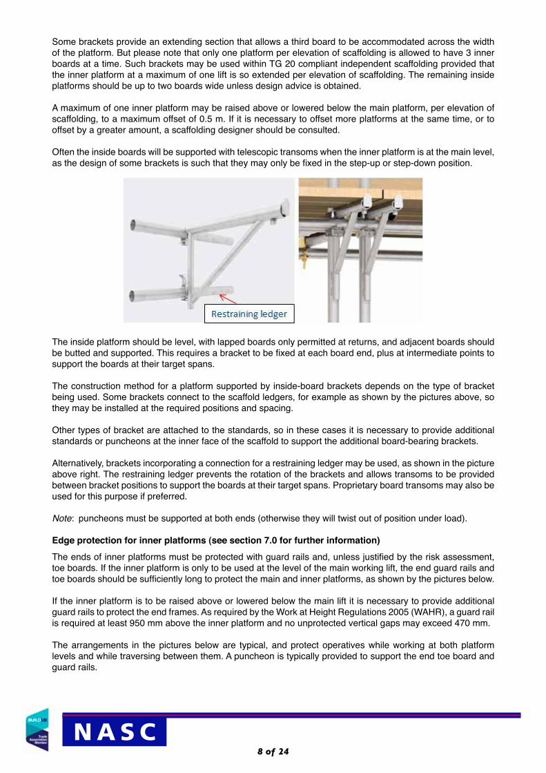
Some brackets provide an extending section that allows a third board to be accommodated across the width of the platform. But please note that only one platform per elevation of scaffolding is allowed to have 3 inner boards at a time. Such brackets may be used within TG 20 compliant independent scaffolding provided that the inner platform at a maximum of one lift is so extended per elevation of scaffolding. The remaining inside platforms should be up to two boards wide unless design advice is obtained.
A maximum of one inner platform may be raised above or lowered below the main platform, per elevation of scaffolding, to a maximum offset of 0.5 m. If it is necessary to offset more platforms at the same time, or to offset by a greater amount, a scaffolding designer should be consulted.
Often the inside boards will be supported with telescopic transoms when the inner platform is at the main level, as the design of some brackets is such that they may only be fixed in the step-up or step-down position.
The inside platform should be level, with lapped boards only permitted at returns, and adjacent boards should be butted and supported. This requires a bracket to be fixed at each board end, plus at intermediate points to support the boards at their target spans.
The construction method for a platform supported by inside-board brackets depends on the type of bracket being used. Some brackets connect to the scaffold ledgers, for example as shown by the pictures above, so they may be installed at the required positions and spacing.
Other types of bracket are attached to the standards, so in these cases it is necessary to provide additional standards or puncheons at the inner face of the scaffold to support the additional board-bearing brackets.
Alternatively, brackets incorporating a connection for a restraining ledger may be used, as shown in the picture above right. The restraining ledger prevents the rotation of the brackets and allows transoms to be provided between bracket positions to support the boards at their target spans. Proprietary board transoms may also be used for this purpose if preferred.
Note: puncheons must be supported at both ends (otherwise they will twist out of position under load).
Edge protection for inner platforms (see section 7.0 for further information)The ends of inner platforms must be protected with guard rails and, unless justified by the risk assessment, toe boards. If the inner platform is only to be used at the level of the main working lift, the end guard rails and toe boards should be sufficiently long to protect the main and inner platforms, as shown by the pictures below.
If the inner platform is to be raised above or lowered below the main lift it is necessary to provide additional guard rails to protect the end frames. As required by the Work at Height Regulations 2005 (WAHR), a guard rail is required at least 950 mm above the inner platform and no unprotected vertical gaps may exceed 470 mm.
The arrangements in the pictures below are typical, and protect operatives while working at both platform levels and while traversing between them. A puncheon is typically provided to support the end toe board and guard rails.

N A S C9 of 24
Longitudinal toe boards may also be required where there is a risk of falling materials.
If the inner platform is stepped downward, toe boards may be placed to prevent materials from falling onto the main platform below, as shown by the picture on the left below. Where the platform is stepped upward, a toe board may be placed at the gap between the main platform and the inner platform, as shown by the picture on the right below. This prevents materials falling from the main platform to the platform below.
A TG 20 compliant inner platform may be raised or lowered by a maximum of 0.5 m without seeking design advice.
5. DESIGN CHANGE
If, during the construction phase, the structure needs to be altered (and/or the structural stability of the scaffold is likely to be affected), the design must be checked by the scaffold designer in consultation with the TF Engineer and if required should be revised and issued to the client/main contractor for approval. However, as a minimum, confirmation must be received from the scaffold designer that it is acceptable to continue.
Consultation with the principal contractor and the Timber Frame Engineer must take place prior to any alterations to the scaffold structure that may affect the timber frame building.
The scaffolding contractor must ensure that any scaffold design changes are communicated to the site management and the scaffold operatives in an appropriate manner before the erection starts or continues.
6. STAbILITY CONSIDERATIONS FOR THE SCAFFOLD DESIGNER
The scaffold designer must put the measures in place to take account of the stability of the scaffold and any wind forces it may be subjected to, including any other imposed loads.
There may not be a building or structure against which to tie (when initially erecting any scaffolding associated with timber frame buildings). Therefore, the stability of the scaffold must be achieved by means other than ties to the building or structure.

N A S C10 of 24
Note: All types of freestanding structures depend for their stability against overturning either on self-weight, additional guys, anchors, outriggers or kentledge and as stated earlier it is important that the work is planned and designed to ensure the appropriate measures can be put in place to maintain stability.
Rakers/outriggers are one method of improving stability, but there are others.
Note: Where kentledge is not used as part of the raking buttress, the scaffold designer will have to ensure the design does not allow the scaffold to “fall forward” into the space allowed for the timber frame (or subsequently fall into the façade itself).
Where there is a risk that the scaffold can “fall forward” – e.g. in cases where the scaffold will remain in place for weeks before timber frame installation – then temporary inner buttresses may be required.
Outer buttresses are often spiked to the ground, whereas inner buttresses may need to use drilled fixings into the slab (if there is one).
Securing ties to beam and block floors can be tricky and design assistance from the permanent works designer may be required. Where a raker or buttress is tied back to the scaffold, pairs of raking tube may also need to be braced together.
Typically rakers may be used in tension and/or compression; for rakers in compression, single un-jointed raking tubes of up to 6m in length fitted at alternate standards, coupled at the top with right angle couplers to the ledger of the second lift, and tied to the scaffold at the foot, can be regarded as providing adequate stability for un-sheeted scaffolds up to 6.0m in height.
When the scaffold structure is being built progressively together with the erection of the timber frame building, ties to the ring beam of the timber frame building structure may be used subject to design.
Where possible the timber frame supplier should predrill or pre-fit components into prefabricated panels that will be subsequently used for scaffold ties.
Designers will decide if the returns of scaffolds, which are themselves effectively tied round the ends of the building facades (e.g. with double couplers), provide an adequate attachment of the scaffold at each lift equivalent to a standard tie positioned at the end of the building façade, or if additional ties are required.
Regularly spaced Buttresses together with some form of Kentledge can be used to improve the stability of the scaffold structure. Kentledge is a form of dead weight, which can be built in or added to a structure to ensure adequate stability. Specifically designed fully braced buttresses can be regarded as providing adequate stability for a single bay of the scaffold on either side of the buttress, special provision, such as suitable plan bracing, should be made to provide restraint to the inner plane of standards parallel to the facade.
6.1 Anchor TiesIt is the responsibility of the Temporary Works Designer/Scaffold Designer to liaise with the Principal contractor, permanent works designer, client and main contractor, to specify the tie loadings required to ensure the stability of the scaffold structure and to agree that the type of tie selected is suitable for use with the Timber Frame Building construction.
For tall structures, it is highly likely that the design will require suitable secure timbers within the structure to be designated by the timber frame designer to be used as scaffold tie anchors. Alternatively, the timber frame designer should make provision for additional robust timbers in key places to be used for scaffold ties.
This may require local strengthening/additional fixings - preferably fabricated in the factory - or by the timber frame erectors on site. The number and location should be determined as early as possible by consultation with the scaffold designer. Please see extract from TG20 pasted below. If required, these suitable timbers

N A S C11 of 24
would need to be installed as per the requirements of the scaffold designer and remain in place throughout the life of the scaffold.
6.2 GuysMany free standing temporary scaffold structures need to be anchored to the ground to resist wind forces. Individual anchor capabilities are dependent on local ground conditions and must be properly assessed in every case.
Temporary stability for large structures during construction, and permanent stability of small structures, may be achieved by using tube anchors attached directly to the bottom of the structure (please refer to NASC Guidance TG16).
It is the responsibility of the scaffold/ temporary works designer to liaise with the Principal contractor/timber frame designer to specify the anchors required and to ensure the stability of the scaffold structure.2
After severe weather conditions it is extremely important that any guy anchorages are inspected. It is recommended that the anchor stakes have some visual indicator attached to them, so that any movement, disturbance or pull out is immediately visible and can be referred back to the scaffold designer and corrected by the scaffold contractor.
For further details, refer to NASC guidance note TG16 Anchoring to the ground.
2 This may require the principal contractor to provide a soils’ report, or to arrange for an assessment to be carried out and an interpretation report to be provided. This information will need to consider the effect of rain and potential for the ground to become waterlogged (which may also include any proposed nearby ground disturbance during the lifetime of the scaffold such as excavation or ground reduction).

N A S C12 of 24
Many free standing temporary scaffoldingstructures, such as access towers, majorsignboards and protection enclosures, need to beanchored to the ground, primarily to resist windforces.
Individual anchor capacities are dependent on localground conditions and so must be properlyassessed, in every case. However, Fig 1 givessome possible solutions employing scaffold tube,with values of the anchor strength which cannormally be achieved in good ground.
For guidance purposes, when tube is embedded aminimum of 300mm in concrete, the interface bondstrength between scaffold tube and concrete maybe taken as 45kN for direct pull out. The first150mm of tube embedment length should beignored in this calculation. Blinding concrete isunlikely to be strong enough.
Prior to anchoring in concrete, contractors mustseek advice from a competent engineer.
There are other proprietary ground anchor systemsavailable. Manufacturers recommendations andinstructions must be complied with.
1 of 4N A S C
TG16:14Anchoring to the Ground
March 2014
Figure 1: Strength of Tube Anchors
6.3 Staircases and Loading baysStair towers, ladder bays, loading bays, buttresses (sometimes known as loading towers) and rakers can be used as an alternative method of maintaining the stability of the structure (as well as kentledge), and this must be taken into consideration at the tender/planning stage (and where required added to the design).
The Client/principal contractor/user must also consider the access and egress requirements to and from the scaffold at the tender/planning stage of the contract and consideration must be given to the hierarchy of access as detailed below in order of preference:
1 Staircases
2 Ladder Access Bays with Single Lift Ladders
3 Ladder Access Bays with Multiple Lift Ladders
4 Internal Ladder Accesses with Protection i.e. ladder trap hatch / handrails etc
5 External Ladder Accesses Using a Safety Gate / Swing Arm System
6 Other
Note: The NASC recommend access points every 30.0m and also that any external ladder access is restricted to the first and second lift only. The Main Contractor’s Site Fire Plan may require additional access/egress points for an evacuation route.
For further details refer to NASC Guidance TG20 or SG25 – Access and Egress from Scaffolds, via Ladders and Stair Towers etc

N A S C13 of 24
7. INTERNAL GUARDRAILS
Timber Frame installers may want no inside guardrails and would prefer to work to their Safe System of Work (SSOW), such as permit to work system.
However, the NASC recommend that the Timber Frame Company produce a Risk Assessment/Method Statement (RAMS) which gives priority to the Work at Height Regulations hierarchy – Collective Fall Preventions measures such as Guardrails used in preference to harnesses – and that installers work behind double guardrails at all times.
To enable timber installers and similar trades to work behind double guardrails on the inside, the NASC recommends two inside boards wherever possible in the design (rather than three (which will be later reduced by one inside board as the brickwork/or similar is progressively raised from the ground upwards) so that timber installers can reach the workface.
Where this is not practicable, timber frame installation companies should instigate a Safe System of Work which prevents falls (e.g. a documented permit to work system).
Edge protection is required at the outer face and the end faces of the scaffold, but it is sometimes necessary to also provide edge protection at the inner face. The Work at Height Regulations require physical edge protection to be provided where personnel or materials could fall and cause injury.
The requirement for internal edge protection depends on the size of the service gap: the gap between the inner edge of the scaffold platform and the building, as illustrated below.
However, because the installation of complete internal edge protection can impede or even prevent certain types of work, a safe system of work, following a risk assessment, may be used in place of some or all internal protection. If the client requests that internal edge protection is not installed this must be recorded on the scaffolding handover certificate.

N A S C14 of 24
The picture on the left shows a gap less than the width of a board, whereas the picture on the right show a gap of approximately one board’s width (225mm). Please note that a gap larger than 225m needs very careful risk assessing.
It may also be prudent for the client/main contractor/user to put in place a Permit to Work system when a single guardrail is used.

N A S C15 of 24
8. DOCUMENTS AND RECORDS
The Scaffolding Contractor should produce a Risk Assessment/Method Statement (RAMS) for each Project (as per NASC Safety Guidance SG7), using the 5 steps to risk assessment recommended by the Health and Safety Executive (HSE):
1 of 16
N A S C
Risk Assessments/Method Statements (RAMS) are integral to all management systems and can be used inisolation, on their own, or integrated; this will be dependent on the activity, the risks and client requirements.RAMS are designed to ensure everyone who can be affected by the activity is considered and hazards areeliminated at source or if this is not possible the risks should be controlled and reduced as far as is reasonablypracticable to an acceptable level, to ensure accidents and incidents do not occur.
A Risk Assessment (RA) is a process of establishing what could cause harm, who may be harmed, what thepotential of the hazard and the people coming together are, what standard controls are in place, and does thehazard’s location / environment present additional risks. The competent person will decide on what can bedone and will detail the residual risks and the required control measures. Only when the RA has beencompleted, reviewed and briefed to the workforce, can works commence.
This RA is usually done in conjunction with a Method Statement (MS), which is also sometimes called a Planof Work or a Scaffold Assembly, Use & Dismantle Plan (AUD).
A Method Statement (AUD Plan) is a systematic process of listing the steps required to complete an activity;this is done in sequential order, and is usually undertaken in conjunction with a RA, to produce a RAMS (oftenalso described as a Safe System of Work).
The templates devised to accompany this safety guidance note are seen as best practice across the industry,and sections can be deleted or added as the activity requires. The templates are there to assist and shouldnot be simply printed off and passed on as being complete documents, once they have been up-dated asnecessary they become the property of the author (and once printed become uncontrolled) however manycompanies will have their own templates which are equally acceptable depending on their own managementsystem, external accreditation i.e. OHSAS 18001 registration and client requirements.
SG7:14Risk Assessments & Method Statements (RAMS)
April 2014
The scaffold contractor must communicate this RAMS to all operatives prior to the erection, alteration and dismantling phases, with signed records retained and the RAMS made available to scaffold operatives on site.
The following documents and records will need to be made available and retained on site during operations:
• Approved Scaffold Design(s);
• Risk Assessment and Method Statement (as detailed above);
• Handover Certificates and Scaffold Inspection Records;
• Tie Tester Calibration Certificate;
• Tie Tests records (these may be encompassed within the Handover note);
• Copies of operatives CISRS cards;
• Other applicable documents and records as per site rules and company procedures and policies.
9. DISMANTLING PROCEDURE
The user must give the scaffolding contractor permission in writing before the Scaffolding can be dismantled (with all trade material and debris cleared off the scaffold).
The scaffold contractor must inspect the scaffold before partial or complete dismantling commences.
The Risk Assessment/Method Statement (RAMS) must be reviewed prior to dismantle and briefed to all operatives (with records retained and a copy made available to scaffold operatives on site).

N A S C16 of 24
All stability measures such as buttresses, ground rakers, ground anchors; ties and buttresses (also used as loading towers) must be removed progressively as the scaffold is dismantled. If the scaffold is dismantled by elevation then design input will be required to ensure no risk of collapse or overturning.
10. REFERENCES
• The Health and Safety at Work Act 1974;
• Construction (Design and Management) Regulations 2015;
• The Management of Health and Safety at Work Regulations 1999;
• The Work at Height Regulations 2005;
• BS 5975 Code of Practice for Temporary Works;
• NASC Safety Guidance, including the following:• SG4 – Preventing Falls in Scaffolding Operations;• SG7 – Risk Assessments & Method Statements;• SG16 – Management of Fall Protection Equipment; • SG19 – A Guide to Formulating a Rescue Plan;• SG25 – Access and Egress from Scaffolds, via Ladders and Stair Towers etc;• SG29 – Internal edge protection on scaffold platforms;• SG32 – Inside Brackets.
• NASC Technical Guidance, including the following:• TG4 – Anchorage systems for scaffolding;• TG20 – Operation Guide / Design Guide;• TG16 – Anchoring to the Ground.
• Structural Timber Association (STA) Guidance documents including the following:• 16 Steps to Fire Safety;• Design Guide to Separating Distances During Construction.
• HSE Guidance, including HSG168 Fire Safety in Construction.
Acknowledgements The NASC would like to acknowledge the following in preparation of this guidance:
• Stewart Milne Timber Systems.
AppendicesAppendix A - Possible Sequential Erection Sketch (Tube & Fitting);Appendix B - Possible Sequential Erection Sketch (System Scaffolding).

N A S C17 of 24
Appendix A – Possible Sequential Erection Sketch (T&F) NOT TO SCALE (minimising alterations to scaffolding)
Picture 2
1.0m
2.0m
2.0m
Sometimes – depending on the height of the first timber section – the timber façade can create safe edge protection once the timber frame is stabilised (thus enabling the inside guardrail to be dismantled once the timber frame affords protection from falls).
Note: stop end toeboards not shown for reasons of clarity.
Where a safety gate has been specified by the Timber Frame Company – to gain access to the inside boards – the NASC recommend that where there is a potential fall on the inside the gate is chained shut until access is needed and only used under an approved permit to work system
1.0 to 1.2m approx
2.0m
2.0m
Picture 1 Some Timber Frame installers may want no inside guardrails and would prefer to work to their Safe System of Work (SSOW), such as permit to work system with their operatives using harnesses etc.
However, the NASC recommend that the Timber Frame Company produce a Risk Assessment/Method Statement (RAMS) which gives priority to the Work at Height Regulations hierarchy – Collective Fall Preventions measures such as Guardrails used in preference to harnesses – and that installers work behind double guardrails at all times.
To enable them to work behind double guardrails on the inside, the NASC recommends two inside boards wherever possible in the design (rather than three (which will be later reduced by one inside board as the brickwork/or similar is progressivel y raised from the ground upwards).
Note: Your specific scaffold design will show any required buttress (and if it also requires kentledge).
The design will also detail the base plate and soleboard configuration (e.g. base plates and 1.2m soleboards).

N A S C18 of 24
Picture 4
1.0m
2.0m
2.0m
1.0m
2.0m
2.0m
Picture 3 Timber Frame installers will fix the next level.
Note: For ease of viewing the other elevations and supports for the timber frame have been omitted.
Note: Where kentledge is not used as part of the raking buttress, the scaffold designer will have to ensure the scaffold cannot “fall forward into” the space allowed for the timber frame or fall into the façade itself.
Timber frame installers will secure the roof in position. Please note that the Timber Frame Company must provide a SSOW for their operatives which complies with the Work at Height Regulations, which precedence given to collective fall prevention methods (e.g. guardrails and temporary birdcage platforms under the roof) over personal (e.g. harnesses).
As detailed before, for ease of viewing, support timbers and other elevations have been omitted.

N A S C19 of 24
1.0m
2.0m
2.0m
Picture 6
1.0m
2.0m
2.0m
Picture 5
Subject to a suitable Risk Assessment, it is possible for bricklayers to commence work at ground level while timber installers complete the roof (with suitable control measures including close boarding the top lift and ensuring timber frame installers do not work directly above bricklayers).
Note: stop end toeboards not shown for reasons of clarity.
Note: where two inside boards are used, scaffolders can finish the inside upright level with the boards on the top lift if required.
Bricklayers (or similar trades) will complete the façade up to either 1.5m or 1.8m high.
N A S C20 of 24
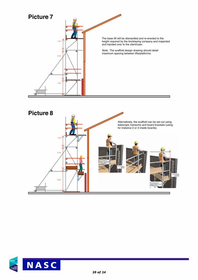
Picture 8
1.0m
2.0m
2.0m
1.0m
2.5m
1.5m
Picture 7
The base lift will be dismantled and re-erected to theheight required by the bricklaying company and inspectedand handed over to the client/user.
Note: The scaffold design drawing should detailmaximum spacing between lifts/platforms.
Alternatively, the scaffold can be set out using telescopic transoms and board brackets (using for instance 2 or 3 inside boards).

N A S C21 of 24
2.0m
1.5m
1.5m
Picture 10
1.0m
2.5m
1.5m
Picture 9
Bricklayers (or similar trades) will complete the façade up to the next height (either 1.5m or 1.8m high)
Timber frame installers will secure the roof in position. Please note that the Timber Frame Company must provide a SSOW for their operatives which complies with the Work at Height Regulations, which precedence given to collective fall prevention methods (e.g. guardrails and temporary birdcage platforms under the roof) over personal (e.g. harnesses).
As detailed before, for ease of viewing, support timbers and other elevations have been omitted.

N A S C22 of 24
1.5m
1.5m
1.5m
Picture 12
2.0m
1.5m
1.5m
Picture 11
Roof work will be completed (as previously described).
Bricklayers (or similar trades) will complete the façade up to the next height (either 1.5m or 1.8m high).
Roof works will have been completed and the top lift cleared of spare material.
The next lift will be dismantled and re-erected to the height required by the bricklaying company (with boards shifted up from below) and inspected and handed over to the client/user.
Bricklayers (or similar trades) will complete the façade up to underneath the eaves (clearing spare on completion).
Note: this simple erection/alteration procedure can be used for taller buildings using the same sequential erection/alteration operations (although please note that the client, timber installers, user and scaffold contractor will have to plan and ensure there are places to tie the scaffold to, as the scaffold rises).

N A S C23 of 24
Appendix b – Possible Sequential Erection Sketch (System Scaffolding) NOT TO SCALE (minimising alterations to scaffolding)
Where a safety gate has been specified by the Timber Frame Company – to gain access to the inside boards – the NASC recommend that where there is a potential fall on the inside the gate is chained shut until access is needed and only used under an approved permit to work system
Some Timber Frame installers may want no inside guardrails and would prefer to work to their Safe System of Work (SSOW), such as permit to work system with their operatives using harnesses etc.
However, the NASC recommend that the Timber Frame Company produce a Risk Assessment/Method Statement (RAMS) which gives priority to the Work at Height Regulations hierarchy – Collective Fall Preventions measures such as Guardrails used in preference to harnesses – and that installers work behind double guardrails at all times.
To enable them to work behind double guardrails on the inside, the NASC recommends two inside decks wherever possible in the design (rather than three (which will be later reduced by one inside deck as the brickwork/or similar is progressively raised from the ground upwards).
Note: Your specific scaffold design will show any required buttress (and if it also requires kentledge).
The design will also detail the screw jacks and soleboard configuration (e.g. screwjacks and 1.2m soleboards).
Picture 1
Picture 2Sometimes – depending on the height of the first timber section – the timber façade can create safe edge protection once the timber frame is stabilised (thus enabling the inside guardrail to be dismantled once the timber frame affords protection from falls).
Note: stop end toeboards not shown for reasons of clarity.

24 of 24
Whilst every effort has been made to provide reliable and accurate information, we would welcome any corrections to information provided by the Writer which may not be entirely accurate, therefore and for this reason, the NASC or indeed the Writer, cannot accept responsibility for any misinformation posted.
NASC, 4th Floor, 12 Bridewell Place, london EC4V 6AP tel: 020 7822 7400 Fax: 020 7822 7401
[email protected] www.nasc.org.ukN A S C
Picture 3
Picture 4
Subject to a suitable Risk Assessment, it is possible for bricklayers to commence work at ground level while timber installers complete the roof (with suitable control measures including close boarding the top lift (e.g. plywood) and ensuring timber frame installers do not work directly above bricklayers).
Note: stop end toeboards not shown for reasons of clarity.
With system scaffolding, it can be possible to shift brackets up and down with the rising brickwork (leaving the main width of scaffolding in place).
Bricklayers (or similar trades) will complete the façade up to underneath the eaves (clearing spare on completion), working on smaller width console brackets (taking into account the thickness of brickwork).
Note: this simple erection/alteration procedure can be used for taller buildings using the same sequential erection/alteration operations (although please note that the client, timber installers, user and scaffold contractor will have to plan and ensure there are places to tie the scaffold to, as the scaffold rises).